Embed Size (px)
Citation preview
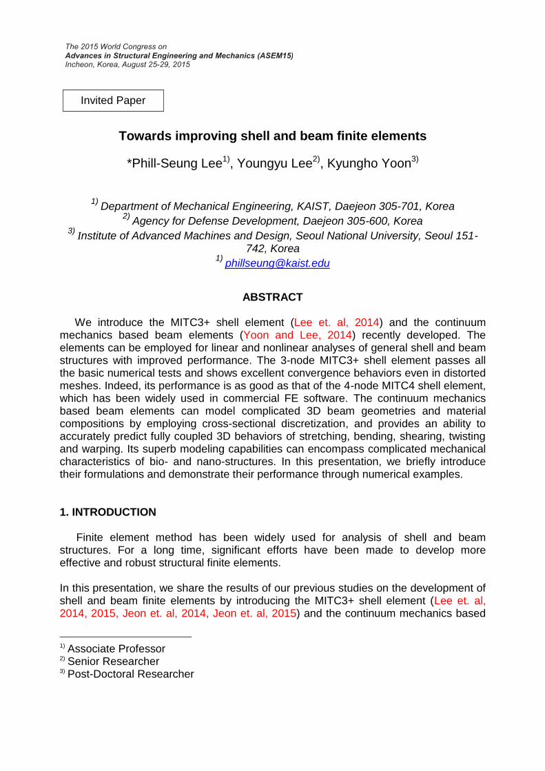
Towards improving shell and beam finite elements
*Phill-Seung Lee1), Youngyu Lee2), Kyungho Yoon3)
1) Department of Mechanical Engineering, KAIST, Daejeon 305-701, Korea
2) Agency for Defense Development, Daejeon 305-600, Korea
3) Institute of Advanced Machines and Design, Seoul National University, Seoul 151-
742, Korea 1)
ABSTRACT We introduce the MITC3+ shell element (Lee et. al, 2014) and the continuum mechanics based beam elements (Yoon and Lee, 2014) recently developed. The elements can be employed for linear and nonlinear analyses of general shell and beam structures with improved performance. The 3-node MITC3+ shell element passes all the basic numerical tests and shows excellent convergence behaviors even in distorted meshes. Indeed, its performance is as good as that of the 4-node MITC4 shell element, which has been widely used in commercial FE software. The continuum mechanics based beam elements can model complicated 3D beam geometries and material compositions by employing cross-sectional discretization, and provides an ability to accurately predict fully coupled 3D behaviors of stretching, bending, shearing, twisting and warping. Its superb modeling capabilities can encompass complicated mechanical characteristics of bio- and nano-structures. In this presentation, we briefly introduce their formulations and demonstrate their performance through numerical examples. 1. INTRODUCTION
Finite element method has been widely used for analysis of shell and beam structures. For a long time, significant efforts have been made to develop more effective and robust structural finite elements. In this presentation, we share the results of our previous studies on the development of shell and beam finite elements by introducing the MITC3+ shell element (Lee et. al, 2014, 2015, Jeon et. al, 2014, Jeon et. al, 2015) and the continuum mechanics based
1)
Associate Professor 2)
Senior Researcher 3)
Post-Doctoral Researcher
Invited Paper
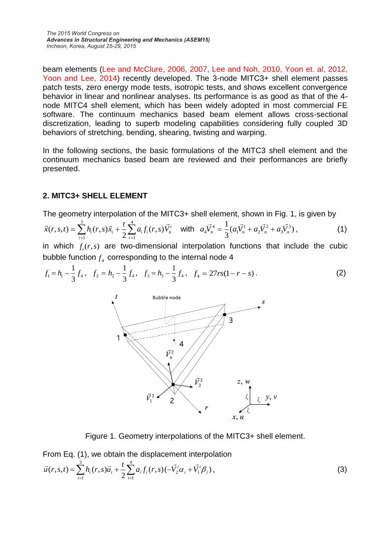
beam elements (Lee and McClure, 2006, 2007, Lee and Noh, 2010, Yoon et. al, 2012, Yoon and Lee, 2014) recently developed. The 3-node MITC3+ shell element passes patch tests, zero energy mode tests, isotropic tests, and shows excellent convergence behavior in linear and nonlinear analyses. Its performance is as good as that of the 4-node MITC4 shell element, which has been widely adopted in most commercial FE software. The continuum mechanics based beam element allows cross-sectional discretization, leading to superb modeling capabilities considering fully coupled 3D behaviors of stretching, bending, shearing, twisting and warping. In the following sections, the basic formulations of the MITC3 shell element and the continuum mechanics based beam are reviewed and their performances are briefly presented. 2. MITC3+ SHELL ELEMENT The geometry interpolation of the MITC3+ shell element, shown in Fig. 1, is given by
4
1
3
1
),(2
),(),,(i
i
nii
i
ii Vsrfat
xsrhtsrx
with )(3
1 3
3
2
2
1
1
4
4 nnnn VaVaVaVa
, (1)
in which ),( srfi are two-dimensional interpolation functions that include the cubic
bubble function4f corresponding to the internal node 4
4113
1fhf , 422
3
1fhf , 433
3
1fhf , )1(274 srrsf . (2)
Figure 1. Geometry interpolations of the MITC3+ shell element.
From Eq. (1), we obtain the displacement interpolation
)(),(2
),(),,( 1
4
1
2
3
1
i
i
i
i
i
ii
i
ii VVsrfat
usrhtsru
, (3)
in which 4 and
4 are the rotation degrees of freedom at the bubble node.
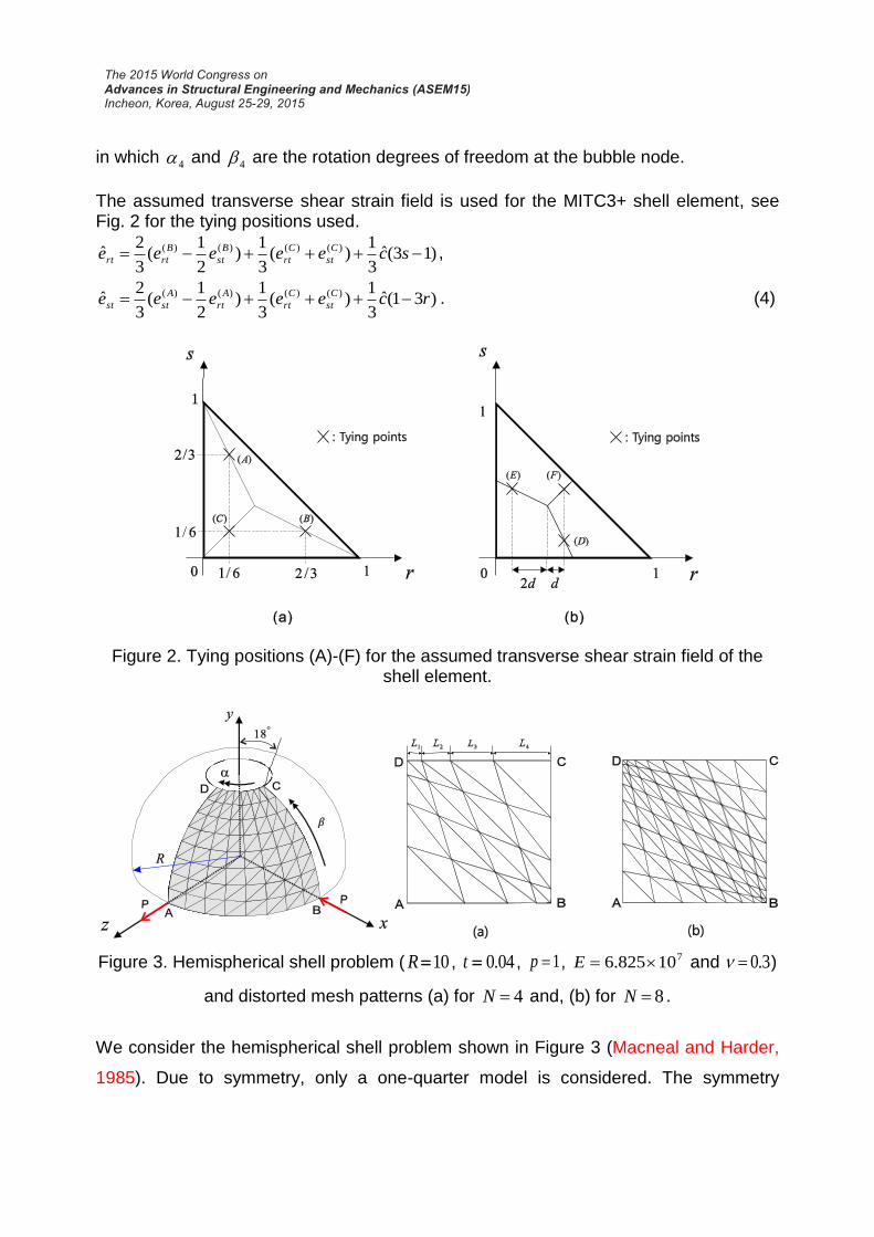
The assumed transverse shear strain field is used for the MITC3+ shell element, see Fig. 2 for the tying positions used.
)13(ˆ3
1)(
3
1)
2
1(
3
2ˆ )()()()( sceeeee C
st
C
rt
B
st
B
rtrt ,
)31(ˆ3
1)(
3
1)
2
1(
3
2ˆ )()()()( rceeeee C
st
C
rt
A
rt
A
stst . (4)
Figure 2. Tying positions (A)-(F) for the assumed transverse shear strain field of the shell element.
Figure 3. Hemispherical shell problem ( 10R , 04.0t , 1p , 710825.6 E and 3.0 )
and distorted mesh patterns (a) for 4N and, (b) for 8N .
We consider the hemispherical shell problem shown in Figure 3 (Macneal and Harder,
1985). Due to symmetry, only a one-quarter model is considered. The symmetry
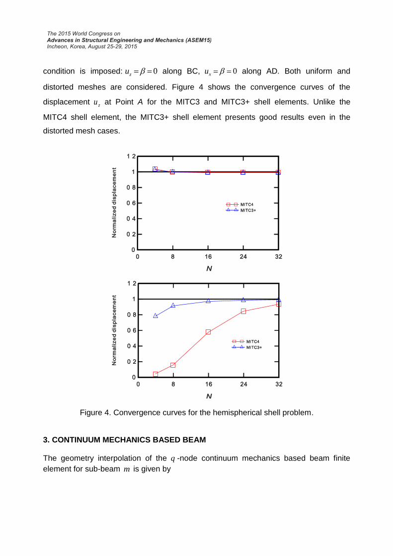
condition is imposed: 0 zu along BC, 0 xu along AD. Both uniform and
distorted meshes are considered. Figure 4 shows the convergence curves of the
displacement zu at Point A for the MITC3 and MITC3+ shell elements. Unlike the
MITC4 shell element, the MITC3+ shell element presents good results even in the
distorted mesh cases.
Figure 4. Convergence curves for the hemispherical shell problem.
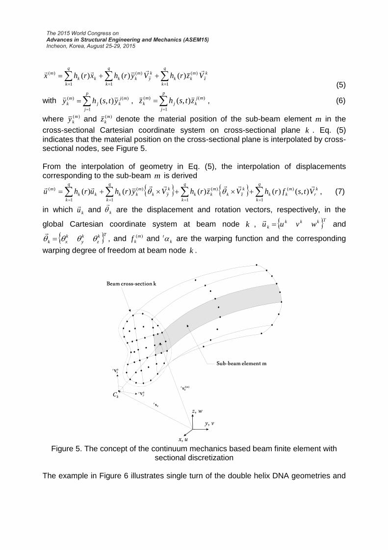
3. CONTINUUM MECHANICS BASED BEAM The geometry interpolation of the q -node continuum mechanics based beam finite
element for sub-beam m is given by
q
k
k
z
m
kk
q
k
k
y
m
kk
q
k
kk
m VzrhVyrhxrhx1
)(
1
)(
1
)( )()()(
(5)
with
p
j
mj
kj
m
k ytshy1
)()( ),( ,
p
j
mj
kj
m
k ztshz1
)()( ),( , (6)
where )(m
ky and )(m
kz denote the material position of the sub-beam element m in the
cross-sectional Cartesian coordinate system on cross-sectional plane k . Eq. (5)
indicates that the material position on the cross-sectional plane is interpolated by cross-sectional nodes, see Figure 5. From the interpolation of geometry in Eq. (5), the interpolation of displacements corresponding to the sub-beam m is derived
k
r
q
k
m
kk
q
k
k
zk
m
kk
q
k
k
yk
m
kk
q
k
kk
m VtsfrhVzrhVyrhurhu
1
)(
1
)(
1
)(
1
)( ),()()()()( , (7)
in which ku
and k
are the displacement and rotation vectors, respectively, in the
global Cartesian coordinate system at beam node k , Tkkk
k wvuu
and
Tk
z
k
y
k
xk
, and )(m
kf and k
t are the warping function and the corresponding
warping degree of freedom at beam node k .
Figure 5. The concept of the continuum mechanics based beam finite element with
sectional discretization The example in Figure 6 illustrates single turn of the double helix DNA geometries and
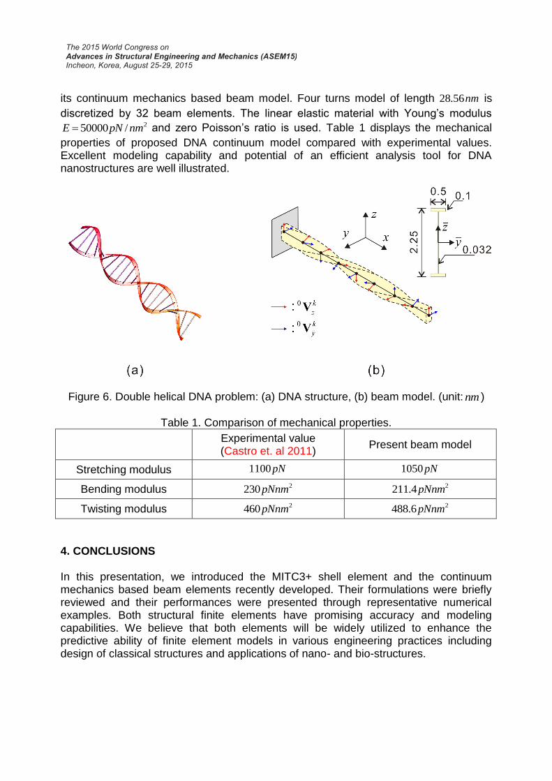
its continuum mechanics based beam model. Four turns model of length nm56.28 is
discretized by 32 beam elements. The linear elastic material with Young’s modulus 2/50000 nmpNE and zero Poisson’s ratio is used. Table 1 displays the mechanical
properties of proposed DNA continuum model compared with experimental values. Excellent modeling capability and potential of an efficient analysis tool for DNA nanostructures are well illustrated.
Figure 6. Double helical DNA problem: (a) DNA structure, (b) beam model. (unit: nm )
Table 1. Comparison of mechanical properties.
Experimental value (Castro et. al 2011)
Present beam model
Stretching modulus pN1100 pN1050
Bending modulus 2230pNnm 24.211 pNnm
Twisting modulus 2460pNnm 26.488 pNnm
4. CONCLUSIONS In this presentation, we introduced the MITC3+ shell element and the continuum mechanics based beam elements recently developed. Their formulations were briefly reviewed and their performances were presented through representative numerical examples. Both structural finite elements have promising accuracy and modeling capabilities. We believe that both elements will be widely utilized to enhance the predictive ability of finite element models in various engineering practices including design of classical structures and applications of nano- and bio-structures.
ACKNOWLEDGEMENTS
This work was supported by the Human Resources Development Program (No. 20134030200300) of the Korea Institute of Energy Technology Evaluation and Planning (KETEP) funded by the Ministry of Trade, Industry and Energy, and the Basic Science Research Program through the National Research Foundation of Korea (NRF) funded by the Ministry of Education, Science and Technology (No. 2014R1A1A1A05007219). REFERENCES Castro, C.E., Kilchherr, F., Kim, D.N., Shiao, E.L., Wauer, T., Wortmann, P., Bathe, M.,
Dietz, H. (2011), “A primer to scaffloded DNA origami”, Nature Methods, 8, 221-229. Jeon, H.M., Lee, Y., Lee, P.S., Bathe, K.J. (2015), “The MITC3+ shell element in
geometric nonlinear analysis”. Computers and Structures, 146, 91-104. Jeon, H.M., Lee, P.S., Bathe, K.J. (2014), “The MITC3 shell finite element enriched by
interpolation covers”. Computers and Structures, 134, 128–142. Lee, P.S., Bathe, K.J. (2004), “Development of MITC isotropic triangular shell finite
elements”. Computers and Structures, 82, 945-962. Lee, Y., Jeon, H.M., Lee, P.S., Bathe, K.J. (2015), “The modal behavior of the MITC3+
triangular shell element”. Computers and Structures, 153, 148-164. Lee, Y., Lee, P.S., Bathe, K.J. (2014), “The MITC3+ shell finite element and its
performance”, Computers and Structures, 138, 12-23. Lee, P.S., McClure, G. (2006), “A general 3D L-section beam finite element for
elastoplastic large deformation analysis”, Computers and Structures, 84(3-4), 215-229.
Lee P.S., McClure G., (2007) “Elastoplastic large deformation analysis of a lattice steel tower structure and comparison with full-scale tests”, Journal of Constructional Steel Research, 63(5), 709-717.
Lee P.S., Noh H.C. (2010) “Inelastic buckling behavior of steel members under reversed cyclic loading”, Engineering Structures, 32(9), 2579-2595.
Macneal, R.H., Harder, R.L. (1985), “A proposed standard set of problems to test finite element accuracy”, Finite Element Analysis and Design, 1, 3-20.
Yoon K., Lee P.S. (2014), “Modeling the warping displacement fields for discontinuously varying arbitrary cross-section beams”. Computers and Structures, 131, 56-69.
Yoon, K., Lee, P.S. (2014), “Nonlinear performance of continuum mechanics based beam elements focusing on large twisting behaviors”, Computer Methods in Applied Mechanics and Engineering, 281, 106-130.
Yoon K, Lee Y, Lee PS. (2012), “A continuum mechanics based 3-D beam finite element with warping displacements and its modeling capabilities”. Structural Engineering and Mechanics, 43(4), 411-437.