Embed Size (px)
Citation preview
8/8/2019 Torres Mnto Series v Cto Cerrado
http://slidepdf.com/reader/full/torres-mnto-series-v-cto-cerrado 1/22
Series V Closed Circuit Cooling Towers andEvaporative Condensers
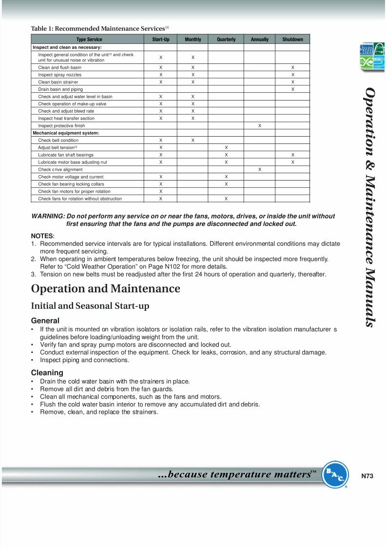
Table of Contents..............................................................PageRecommended Maintenance Services . . . . . . . . . . . . . . . . . . . . . . . . . . . . . . . . . . . . . . . . . . . . . . . . . . . . .N73
Operation and Maintenance . . . . . . . . . . . . . . . . . . . . . . . . . . . . . . . . . . . . . . . . . . . . . . . . . . . . . . . . . . . . .N73Initial and Seasonal Start-Up . . . . . . . . . . . . . . . . . . . . . . . . . . . . . . . . . . . . . . . . . . . . . . . . . . . . . .N73
Extended Shutdown . . . . . . . . . . . . . . . . . . . . . . . . . . . . . . . . . . . . . . . . . . . . . . . . . . . . . . . . . . . . .N74
Detailed Component Maintenance Procedures . . . . . . . . . . . . . . . . . . . . . . . . . . . . . . . . . . . . . . . . . . . . . .N75
Cold Water Basin . . . . . . . . . . . . . . . . . . . . . . . . . . . . . . . . . . . . . . . . . . . . . . . . . . . . . . . . . . . . . . .N75
Fan . . . . . . . . . . . . . . . . . . . . . . . . . . . . . . . . . . . . . . . . . . . . . . . . . . . . . . . . . . . . . . . . . . . . . . . . . .N76
Fan Drive System . . . . . . . . . . . . . . . . . . . . . . . . . . . . . . . . . . . . . . . . . . . . . . . . . . . . . . . . . . . . . . .N76
Fan Motors . . . . . . . . . . . . . . . . . . . . . . . . . . . . . . . . . . . . . . . . . . . . . . . . . . . . . . . . . . . . . . . . . . . .N77
Fan Shaft Bearings . . . . . . . . . . . . . . . . . . . . . . . . . . . . . . . . . . . . . . . . . . . . . . . . . . . . . . . . . . . . .N77
Sleeve Bearings . . . . . . . . . . . . . . . . . . . . . . . . . . . . . . . . . . . . . . . . . . . . . . . . . . . . . . . . . . . . . . . .N78
Locking Collars . . . . . . . . . . . . . . . . . . . . . . . . . . . . . . . . . . . . . . . . . . . . . . . . . . . . . . . . . . . . . . . . .N78
Water Distribution System . . . . . . . . . . . . . . . . . . . . . . . . . . . . . . . . . . . . . . . . . . . . . . . . . . . . . . . .N78
Water Level Control . . . . . . . . . . . . . . . . . . . . . . . . . . . . . . . . . . . . . . . . . . . . . . . . . . . . . . . . . . . . .N79
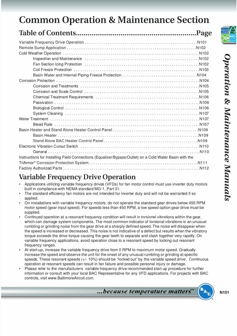
Figure 1 - VFL Closed Circuit Cooling Tower and VCLEvaporative Condenser
Fan Shaft and Bearing
V-Belt Drive Systemwith Guard
Fan Motor
Spray NozzlesEliminators
Spray Branches
Coil
Access Door
Spray Pump
N
...because temperature matters
™
8/8/2019 Torres Mnto Series v Cto Cerrado
http://slidepdf.com/reader/full/torres-mnto-series-v-cto-cerrado 2/22
S e r i e s
V C o i l P r o d u c t s
N72 Baltimore Aircoil Company
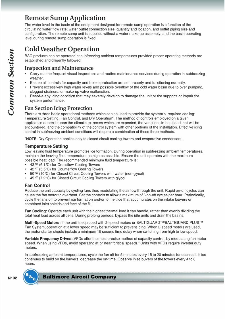
Casing
Coil
Spray Nozzles
Spray Branches
Eliminators
Fan Housing
Fan Screens
Fan
Fan ShaftFan Bearing
Fan Drives
Fan Motor
Water Bleed Line
Spray Pump
Strainer
Adjustable Float
Water Make-up Valve Assembly
Figure 2a - Heat Transfer Coil Section for VF1 Closed Circuit Cooling Tower and VC1
Evaporative Condenser
Figure 2b - Basin Section for VF1 Closed Circuit Cooling Tower and
VC1 Evaporative Condenser
8/8/2019 Torres Mnto Series v Cto Cerrado
http://slidepdf.com/reader/full/torres-mnto-series-v-cto-cerrado 3/22
8/8/2019 Torres Mnto Series v Cto Cerrado
http://slidepdf.com/reader/full/torres-mnto-series-v-cto-cerrado 4/22
S e r i e s
V C o i l P r o d u c t s
N74 Baltimore Aircoil Company
Inspection
WARNING: Do not perform any service on or near the fans, motors, drives, or inside the unit without first ensuring that the fans and the pumps are disconnected and locked out.
• At seasonal start-up or after prolonged shutdown, check the motorinsulation with an insulation tester prior to the motor start-up.
• Prior to the seasonal start-up, check and adjust the belt tension. Atthe initial start-up, the belt tension may not require adjustment as
the drive will be properly tensioned at the factory prior to shipment.• Start the fan motors and check for proper fan rotation.• Run the fans in manual mode for several minutes to check for any
unusual noise or vibrations.• Check that the float operated make-up valve is operating freely.
WARNING: Check to ensure the controls for the fan motors are set to allow a maximum of 6 on-off cycles per hour.
Start-up
WARNING: Do not perform any service on or near the fans,motors, and drives, or inside the unit without first ensuring that the fans and the
pumps are disconnected and locked out.
• Prior to seasonal start-up, lubricate the motor base adjusting screws (see Figure 6 on Page N77) and thefan shaft bearings. At initial start-up, no bearing lubrication is required since the bearings are factorylubricated prior to shipment.
• Fill the cold water basin with fresh water to the overflow level via the make-up valve.o Water treatment for new installations: Initiate the biocide water treatment program at this time. Refer to
“Biological Control” on Page N106 for more details.o Water treatment for seasonal start-up or after a shutdown period in excess of 3 days: Resume the
biocide treatment program and administer a shock treatment of appropriate biocides prior to operatingthe fans. This will eliminate accumulated biological contaminants. Refer to “Biological Control” onPage N106 for more details.
• Set the make-up valve float so the water shuts off at the overflow level.• Start the spray pump. See “Water Distribution System” on Page N78 for more details.• Open the valve in the unit bleed line, and adjust the bleed by closing or opening the valve.• Once the unit is operating, check the current and voltage of all three phases (legs) of the fan motors with a
heat load on the unit under warm ambient conditions. The current must not exceed the nameplate ratings.• Check the operation of the optional vibration cutout switch.
After 24 hours of operation under thermal load, perform the following services:
• Check the unit for any unusual noise or vibrations.• Check the operating water level in the cold water basin.• Adjust make-up valve if necessary.• Check the belt tension and readjust if necessary.
Extended Shutdown
WARNING: Do not perform any service on or near the fans, motors, and drives, or inside the unit
without first ensuring that the fans and the pumps are disconnected and locked out.
Perform the following services whenever the unit is shutdown in excess of 3 days:• If the unit is mounted on vibration isolators or isolation rails, refer to the manufacturer’s guidelines before
loading/unloading weight from the unit.• Drain the cold water basin and all the piping (excluding the coils) that will be exposed to freezing
temperatures. Heat trace and insulate all exposed piping.
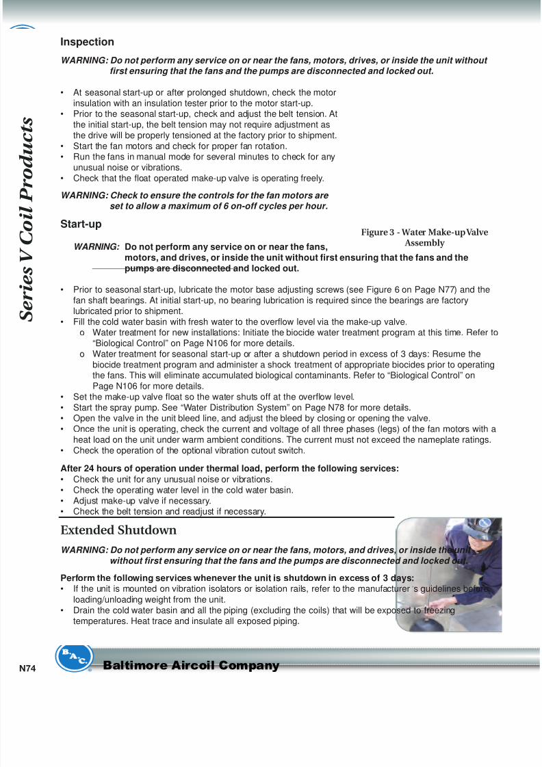
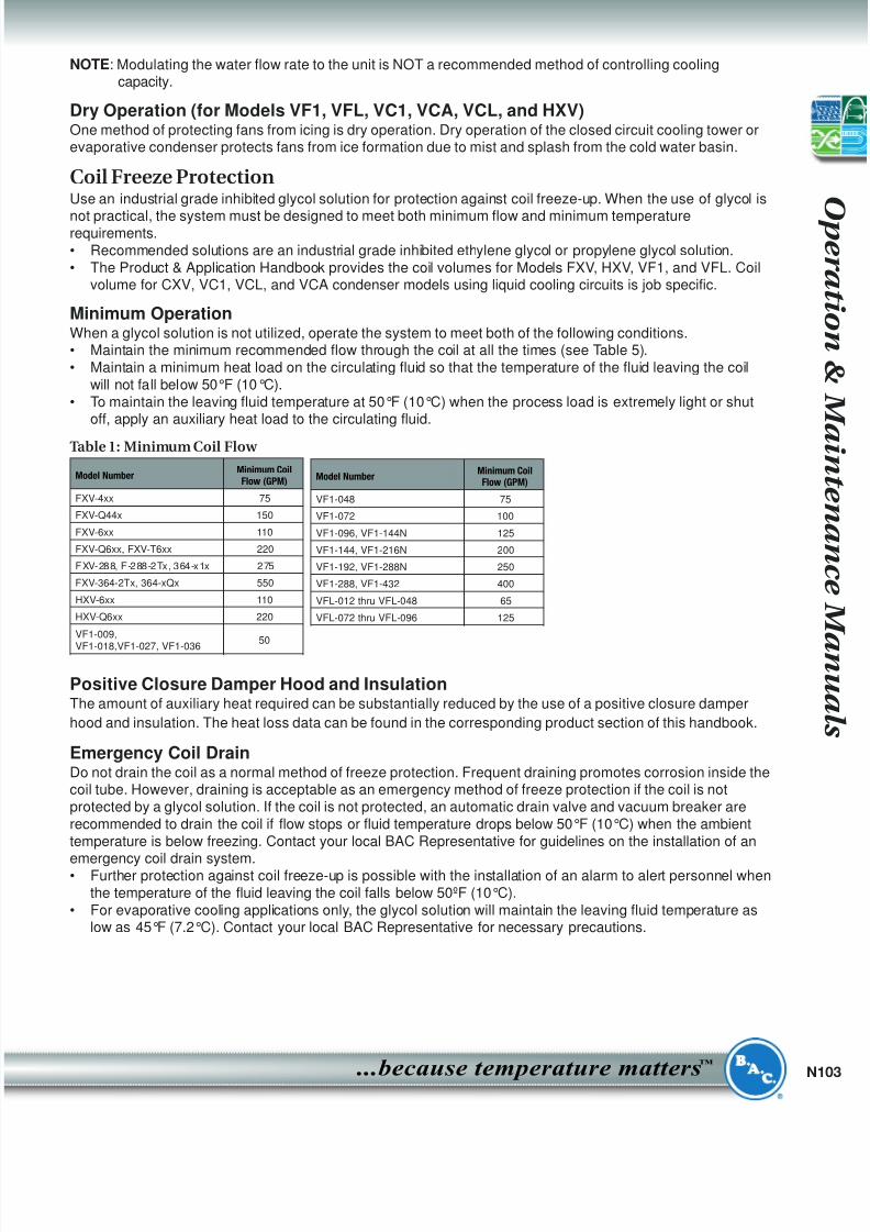
Figure 3 - Water Make-upValve Assembly
8/8/2019 Torres Mnto Series v Cto Cerrado
http://slidepdf.com/reader/full/torres-mnto-series-v-cto-cerrado 5/22
N
...because temperature matters
™
• Clean all debris, such as leaves and dirt, from the interior and exterior of the unit.• Clean and flush the cold water basin with the basin strainers in place.• Leave the cold water basin drain open so rain and melting snow will drain from the unit.• Clean the basin strainer and re-install.• Lubricate the fan shaft bearings, motor base, and motor base adjusting screw.• Close the shut off valve in the make-up water line (supplied by others), and drain all exposed make-up
water piping. Heat trace and insulate all exposed piping.• Inspect the protective finish on the unit. Clean and refinish as required. Refer to “Corrosion Protection” on
Page N104 for more details.
• Secure the fan motors starting device(s) in the “OFF” position to ensure personal safety in case of futureinspection or service.
Detailed Component Maintenance Procedures
Cold Water BasinThe fluid to be cooled is circulated inside the tubes of the unit's heat exchanger. Heat flows from the processfluid through the coil to the spray water outside which is cascading over the tubes. The spray water collects inthe cold water basin, passes through the suction strainer and is pumped back to the distribution system. Thecold water basin is constructed from one of the following materials of construction:• Galvanized steel
• Thermosetting Hybrid Polymer• Type 304 stainless steel
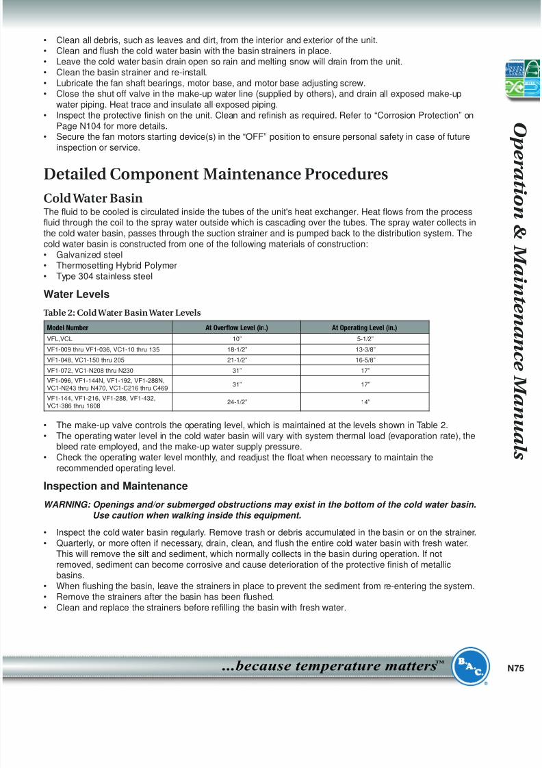
Water Levels
Table 2: Cold Water Basin Water Levels
• The make-up valve controls the operating level, which is maintained at the levels shown in Table 2.• The operating water level in the cold water basin will vary with system thermal load (evaporation rate), the
bleed rate employed, and the make-up water supply pressure.• Check the operating water level monthly, and readjust the float when necessary to maintain the
recommended operating level.
Inspection and Maintenance
WARNING: Openings and/or submerged obstructions may exist in the bottom of the cold water basin.
Use caution when walking inside this equipment.
• Inspect the cold water basin regularly. Remove trash or debris accumulated in the basin or on the strainer.• Quarterly, or more often if necessary, drain, clean, and flush the entire cold water basin with fresh water.
This will remove the silt and sediment, which normally collects in the basin during operation. If notremoved, sediment can become corrosive and cause deterioration of the protective finish of metallicbasins.
• When flushing the basin, leave the strainers in place to prevent the sediment from re-entering the system.• Remove the strainers after the basin has been flushed.• Clean and replace the strainers before refilling the basin with fresh water.
Model Number At Overflow Level (in.) At Operating Level (in.)
VFL,VCL 10” 5-1/2”
VF1-009 thru VF1-036, VC1-10 thru 135 18-1/2” 13-3/8”
VF1-048, VC1-150 thru 205 21-1/2” 16-5/8”
VF1-072, VC1-N208 thru N230 31” 17”
VF1-096, VF1-144N, VF1-192, VF1-288N,VC1-N243 thru N470, VC1-C216 thru C469
31” 17”
VF1-144, VF1-216, VF1-288, VF1-432,
VC1-386 thru 1608 24-1/2” 14”
8/8/2019 Torres Mnto Series v Cto Cerrado
http://slidepdf.com/reader/full/torres-mnto-series-v-cto-cerrado 6/22
S e r i e s
V C o i l P r o d u c t s
N76 Baltimore Aircoil Company
• Adjust the float to maintain the design operating level. See Table 2: “Cold Water Basin Water Levels”.
FanSeries V Closed Circuit Cooling Towers and Evaporative Condensers use centrifugal fans. Thoroughly inspectthe fans for damaged or deteriorated fan blades and replace the fan as required.
Inspection and Maintenance• If the unit is already in operation, while the fans are still running, check for any unusual noise or vibration.• With the fans off and the motor locked out and tagged, check the general condition of the fans:
o Inspect for any loose or missing bolts in the locking collar and fan shaft bearings.• Rotation: Turn the fan shaft by hand to ensure that the shaft moves freely with no rough spots, binding or
other malfunctions that could cause vibration or fan motor overload.• Direction of Rotation: On initial start-up, or if the fan motor has been rewired, bump the fan motor and
note the direction of rotation.• Operation: On initial start-up, run the fan in the manual position for several minutes and check for any
unusual noises or vibration.
Fan Drive System
Inspection and Maintenance• These drives require a periodic check of the belt condition and, when necessary, tension adjustment. The
recommended service intervals are as follows:
o Initial Start-up: Servicing is not required prior to initial unit start-up. The drive has been tensioned andaligned at the factory.
o Seasonal Start-up: Readjust the belt tension.o Operation: After the first 24 hours of operation, readjust the belt tension on a new unit start-up or
installation of a new belt. Thereafter, check the belt condition monthly, and adjust tension asnecessary. Readjust tension at least once every 3 months.
• Belt tension check:o Place a straight edge along the belt from sheave to sheave as shown in Figure 4a, or use a tape
measure as shown in Figure 4b, to measure belt deflection.o Apply a moderate force by hand (approximately 15 lbs/6.8 kg) evenly across the width of the belt in
the center of the span between the sheaves.o There is adequate belt tension if the belt deflects between 1/4” and 3/8” as shown in Figures 4a and
4b.
• Belt tension adjustment (if required):o Loosen the lock nut on the motor base adjusting screw.o Turn the motor base adjusting screw clockwise to tension the belt, or counterclockwise to relieve belt
tension. During adjustment of belt tension, rotate the drives several times by hand to evenly distributethe tension throughout the belt.
• When the belt is properly tensioned, retighten the lock nut on the motor base adjusting screw.
NOTE: There should be no “chirp” or “squeal” when the fan motor is started.
DRIVEN SHEAVERVEN SHEAVE
BELTELT
DRIVERSHEAVERVERSHEAVE
STRAIGHT EDGETRAIGHT EDGE
1/4” TO 3/8” DEFLECTION = PROPERBELTTENSION3/8” D EFLECTION = PROPER BELT TENSO N
DRIVEN SHEAVERVEN SHEAVEBELTELT
DRIVER SHEAVERVERSHEAVE
TAPEMEASUREAPEM EASURE
1/4” TO 3/8” DEFLECTION = PROPER BELTTENSION/8” D EFLECTION = PROPER BELT TENS ON
Figure 4a Figure 4b
8/8/2019 Torres Mnto Series v Cto Cerrado
http://slidepdf.com/reader/full/torres-mnto-series-v-cto-cerrado 7/22
N
...because temperature matters
™
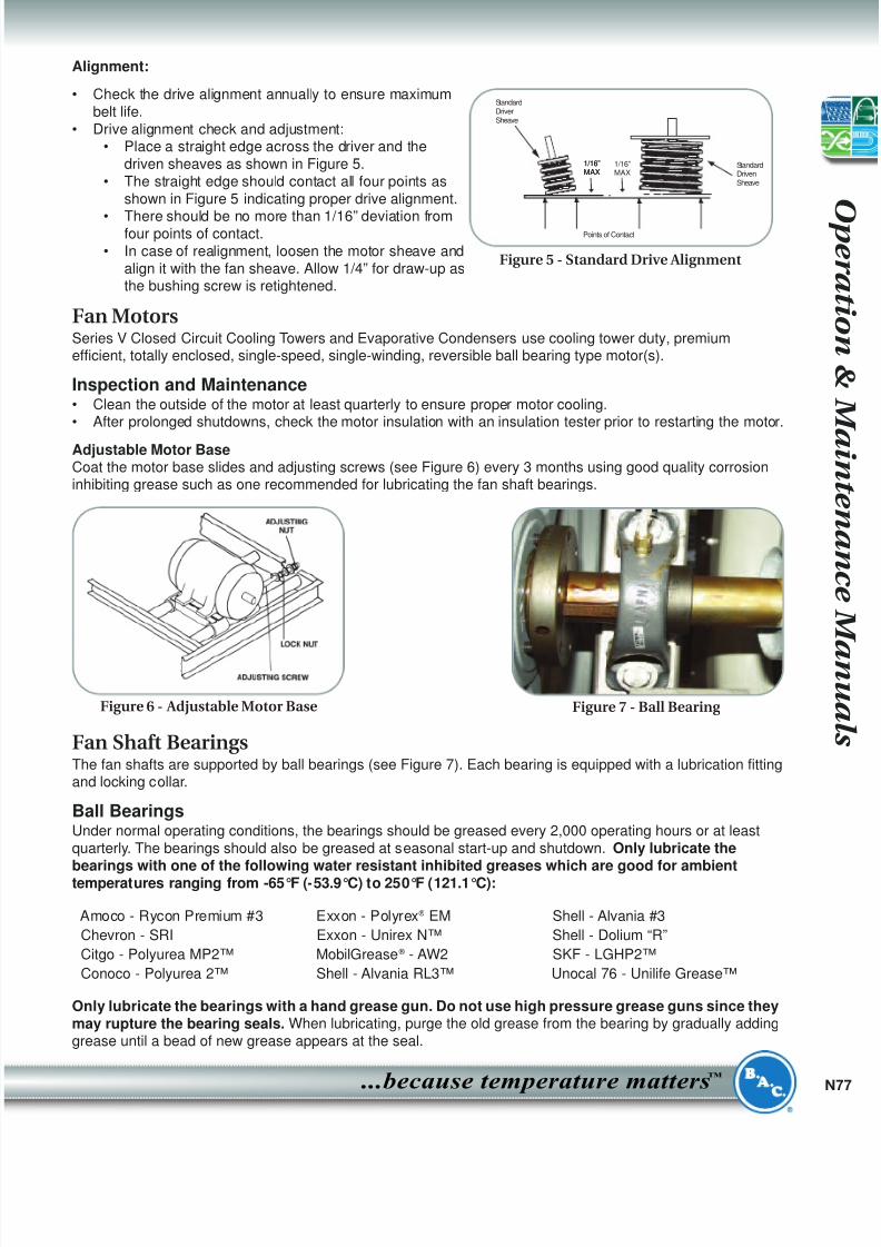
Alignment:
• Check the drive alignment annually to ensure maximumbelt life.
• Drive alignment check and adjustment:• Place a straight edge across the driver and the
driven sheaves as shown in Figure 5.• The straight edge should contact all four points as
shown in Figure 5 indicating proper drive alignment.
• There should be no more than 1/16” deviation fromfour points of contact.
• In case of realignment, loosen the motor sheave andalign it with the fan sheave. Allow 1/4” for draw-up asthe bushing screw is retightened.
Fan MotorsSeries V Closed Circuit Cooling Towers and Evaporative Condensers use cooling tower duty, premiumefficient, totally enclosed, single-speed, single-winding, reversible ball bearing type motor(s).
Inspection and Maintenance• Clean the outside of the motor at least quarterly to ensure proper motor cooling.• After prolonged shutdowns, check the motor insulation with an insulation tester prior to restarting the motor.
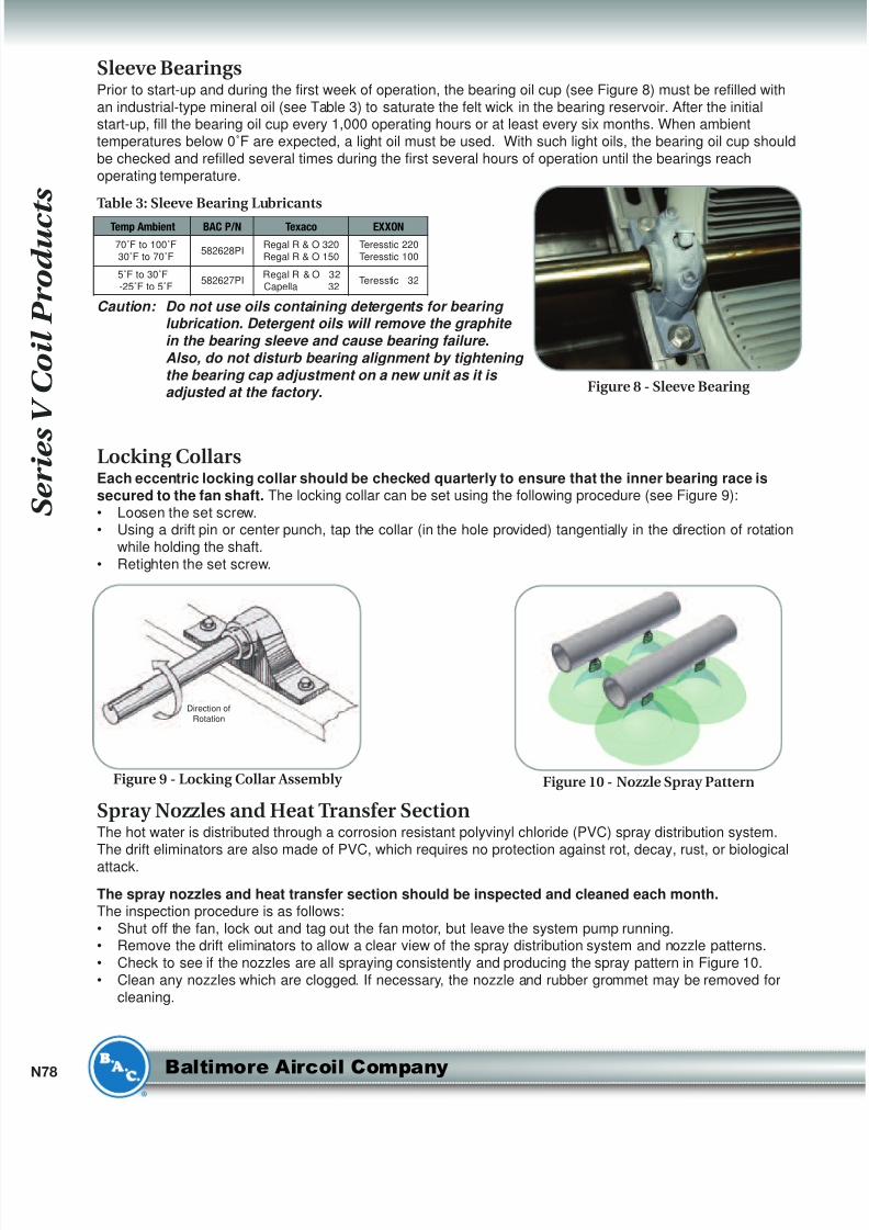
Adjustable Motor BaseCoat the motor base slides and adjusting screws (see Figure 6) every 3 months using good quality corrosioninhibiting grease such as one recommended for lubricating the fan shaft bearings.
Fan Shaft BearingsThe fan shafts are supported by ball bearings (see Figure 7). Each bearing is equipped with a lubrication fittingand locking collar.
Ball BearingsUnder normal operating conditions, the bearings should be greased every 2,000 operating hours or at leastquarterly. The bearings should also be greased at seasonal start-up and shutdown. Only lubricate thebearings with one of the following water resistant inhibited greases which are good for ambienttemperatures ranging from -65°F (-53.9°C) to 250°F (121.1°C):
Only lubricate the bearings with a hand grease gun. Do not use high pressure grease guns since theymay rupture the bearing seals. When lubricating, purge the old grease from the bearing by gradually addinggrease until a bead of new grease appears at the seal.
Amoco - Rycon Premium #3 Exxon - Polyrex ® EM Shell - Alvania #3
Chevron - SRI Exxon - Unirex N™ Shell - Dolium “R”
Citgo - Polyurea MP2™ MobilGrease ® - AW2 SKF - LGHP2™
Conoco - Polyurea 2™ Shell - Alvania RL3™ Unocal 76 - Unilife Grease™
Figure 7 - Ball BearingFigure 6 - Adjustable Motor Base
Points of Contact
Standard
Driver
Sheave
1/16”
MAX
1/16”
MAX
1/16”
MAX
Standard
Driven
Sheave
Figure 5 - Standard Drive Alignment
8/8/2019 Torres Mnto Series v Cto Cerrado
http://slidepdf.com/reader/full/torres-mnto-series-v-cto-cerrado 8/22
S e r i e s
V C o i l P r o d u c t s
N78 Baltimore Aircoil Company
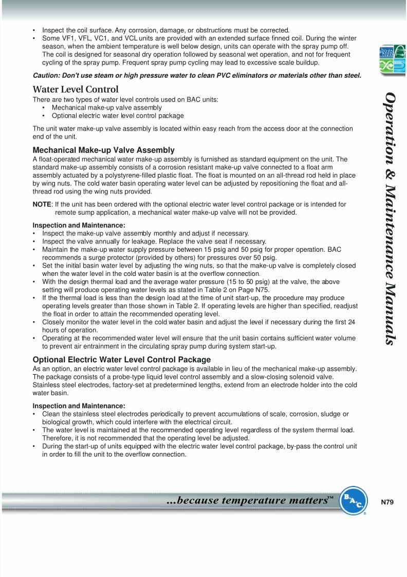
Sleeve BearingsPrior to start-up and during the first week of operation, the bearing oil cup (see Figure 8) must be refilled withan industrial-type mineral oil (see Table 3) to saturate the felt wick in the bearing reservoir. After the initialstart-up, fill the bearing oil cup every 1,000 operating hours or at least every six months. When ambienttemperatures below 0˚F are expected, a light oil must be used. With such light oils, the bearing oil cup shouldbe checked and refilled several times during the first several hours of operation until the bearings reachoperating temperature.
Table 3: Sleeve Bearing Lubricants
Caution: Do not use oils containing detergents for bearing lubrication. Detergent oils will remove the graphite
in the bearing sleeve and cause bearing failure.
Also, do not disturb bearing alignment by tightening
the bearing cap adjustment on a new unit as it is adjusted at the factory.
Locking CollarsEach eccentric locking collar should be checked quarterly to ensure that the inner bearing race issecured to the fan shaft. The locking collar can be set using the following procedure (see Figure 9):• Loosen the set screw.• Using a drift pin or center punch, tap the collar (in the hole provided) tangentially in the direction of rotation
while holding the shaft.• Retighten the set screw.
Spray Nozzles and Heat Transfer SectionThe hot water is distributed through a corrosion resistant polyvinyl chloride (PVC) spray distribution system.The drift eliminators are also made of PVC, which requires no protection against rot, decay, rust, or biological
attack.
The spray nozzles and heat transfer section should be inspected and cleaned each month.The inspection procedure is as follows:• Shut off the fan, lock out and tag out the fan motor, but leave the system pump running.• Remove the drift eliminators to allow a clear view of the spray distribution system and nozzle patterns.• Check to see if the nozzles are all spraying consistently and producing the spray pattern in Figure 10.• Clean any nozzles which are clogged. If necessary, the nozzle and rubber grommet may be removed for
cleaning.
Figure 9 - Locking Collar Assembly
Direction ofRotation
Figure 10 - Nozzle Spray Pattern
Figure 8 - Sleeve Bearing
Temp Ambient BAC P/N Texaco EXXON
70˚F to 100˚F30˚F to 70˚F
582628PIRegal R & O 320Regal R & O 150
Teresstic 220Teresstic 100
5˚F to 30˚F-25˚F to 5˚F
582627PIRegal R & O 32Capella 32
Teresstic 32
8/8/2019 Torres Mnto Series v Cto Cerrado
http://slidepdf.com/reader/full/torres-mnto-series-v-cto-cerrado 9/22
N
...because temperature matters
™
• Inspect the coil surface. Any corrosion, damage, or obstructions must be corrected.• Some VF1, VFL, VC1, and VCL units are provided with an extended surface finned coil. During the winter
season, when the ambient temperature is well below design, units can operate with the spray pump off.The coil is designed for seasonal dry operation followed by seasonal wet operation, and not for frequentcycling of the spray pump. Frequent spray pump cycling may lead to excessive scale buildup.
Caution: Don't use steam or high pressure water to clean PVC eliminators or materials other than steel.
Water Level Control
There are two types of water level controls used on BAC units:• Mechanical make-up valve assembly• Optional electric water level control package
The unit water make-up valve assembly is located within easy reach from the access door at the connectionend of the unit.
Mechanical Make-up Valve AssemblyA float-operated mechanical water make-up assembly is furnished as standard equipment on the unit. Thestandard make-up assembly consists of a corrosion resistant make-up valve connected to a float armassembly actuated by a polystyrene-filled plastic float. The float is mounted on an all-thread rod held in placeby wing nuts. The cold water basin operating water level can be adjusted by repositioning the float and all-thread rod using the wing nuts provided.
NOTE: If the unit has been ordered with the optional electric water level control package or is intended forremote sump application, a mechanical water make-up valve will not be provided.
Inspection and Maintenance:• Inspect the make-up valve assembly monthly and adjust if necessary.• Inspect the valve annually for leakage. Replace the valve seat if necessary.• Maintain the make-up water supply pressure between 15 psig and 50 psig for proper operation. BAC
recommends a surge protector (provided by others) for pressures over 50 psig.• Set the initial basin water level by adjusting the wing nuts, so that the make-up valve is completely closed
when the water level in the cold water basin is at the overflow connection.• With the design thermal load and the average water pressure (15 to 50 psig) at the valve, the above
setting will produce operating water levels as stated in Table 2 on Page N75.• If the thermal load is less than the design load at the time of unit start-up, the procedure may produce
operating levels greater than those shown in Table 2. If operating levels are higher than specified, readjustthe float in order to attain the recommended operating level.
• Closely monitor the water level in the cold water basin and adjust the level if necessary during the first 24hours of operation.
• Operating at the recommended water level will ensure that the unit basin contains sufficient water volumeto prevent air entrainment in the circulating spray pump during system start-up.
Optional Electric Water Level Control PackageAs an option, an electric water level control package is available in lieu of the mechanical make-up assembly.The package consists of a probe-type liquid level control assembly and a slow-closing solenoid valve.Stainless steel electrodes, factory-set at predetermined lengths, extend from an electrode holder into the coldwater basin.
Inspection and Maintenance:• Clean the stainless steel electrodes periodically to prevent accumulations of scale, corrosion, sludge or
biological growth, which could interfere with the electrical circuit.• The water level is maintained at the recommended operating level regardless of the system thermal load.
Therefore, it is not recommended that the operating level be adjusted.• During the start-up of units equipped with the electric water level control package, by-pass the control unit
in order to fill the unit to the overflow connection.
8/8/2019 Torres Mnto Series v Cto Cerrado
http://slidepdf.com/reader/full/torres-mnto-series-v-cto-cerrado 10/22
S p a r e P a r t s
N80 Baltimore Aircoil Company
Recommended Spa re PartsBAC parts are the “Perfect Fit” for your cooling tower. These parts are specifically designed, engineered and
manufactured to work in a cooling tower environment. They are the right parts, at competitive pricing levels, and
BAC offers the best deliveries in the industry.
BAC stocks most common repair and retrofit parts in our Parts DepotSM and can ship other parts, often overnight,
from any of our three manufacturing facilities strategically located in California, Delaware, and Illinois. In addition,
most BAC Representatives maintain a local inventory of commonly used parts.
Even with this fast delivery capability, it is still recommended that certain essential, emergency repair parts be
maintained in your local inventory, to minimize any potential downtime.
Basic Recommended Spare PartsBearing set
Float valve or repair kit
Float ball
Solenoid valve (if unit is equipped with electric water level control)
Powerband or set of belts
Spray nozzle kit with grommets
Basin heater and low water cut out
Door gasket
Strainer (inlet and suction)
Fan and sheave bushingsPump seal and gasket kit for coil products
Automatic bearing greaser refill kit
Parts to Consider if Extended Downtime is a ConcernSpray pump for coil products
Fan or fan wheel
Fan shaft
Sheave setFan motor
8/8/2019 Torres Mnto Series v Cto Cerrado
http://slidepdf.com/reader/full/torres-mnto-series-v-cto-cerrado 11/22
Common Operation & Maintenance Section
Table of Contents..............................................................PageVariable Frequency Drive Operation . . . . . . . . . . . . . . . . . . . . . . . . . . . . . . . . . . . . . . . . . . . . . . . . . . . . . .N101
Remote Sump Application . . . . . . . . . . . . . . . . . . . . . . . . . . . . . . . . . . . . . . . . . . . . . . . . . . . . . . . . . . . . . .N102
Cold Weather Operation . . . . . . . . . . . . . . . . . . . . . . . . . . . . . . . . . . . . . . . . . . . . . . . . . . . . . . . . . . . . . . .N102
Inspection and Maintenance . . . . . . . . . . . . . . . . . . . . . . . . . . . . . . . . . . . . . . . . . . . . . . . . . . . . .N102Fan Section Icing Protection . . . . . . . . . . . . . . . . . . . . . . . . . . . . . . . . . . . . . . . . . . . . . . . . . . . . .N102
Coil Freeze Protection . . . . . . . . . . . . . . . . . . . . . . . . . . . . . . . . . . . . . . . . . . . . . . . . . . . . . . . . . .N103
Basin Water and Internal Piping Freeze Protection . . . . . . . . . . . . . . . . . . . . . . . . . . . . . . . . . . . .N104
Corrosion Protection . . . . . . . . . . . . . . . . . . . . . . . . . . . . . . . . . . . . . . . . . . . . . . . . . . . . . . . . . . . . . . . . . .N104
Corrosion and Treatments . . . . . . . . . . . . . . . . . . . . . . . . . . . . . . . . . . . . . . . . . . . . . . . . . . . . . . .N105
Corrosion and Scale Control . . . . . . . . . . . . . . . . . . . . . . . . . . . . . . . . . . . . . . . . . . . . . . . . . . . . .N105
Chemical Treatment Requirements . . . . . . . . . . . . . . . . . . . . . . . . . . . . . . . . . . . . . . . . . . . . . . . .N106
Passivation . . . . . . . . . . . . . . . . . . . . . . . . . . . . . . . . . . . . . . . . . . . . . . . . . . . . . . . . . . . . . . . . . . .N106
Biological Control . . . . . . . . . . . . . . . . . . . . . . . . . . . . . . . . . . . . . . . . . . . . . . . . . . . . . . . . . . . . . .N106
System Cleaning . . . . . . . . . . . . . . . . . . . . . . . . . . . . . . . . . . . . . . . . . . . . . . . . . . . . . . . . . . . . . .N107
Water Treatment . . . . . . . . . . . . . . . . . . . . . . . . . . . . . . . . . . . . . . . . . . . . . . . . . . . . . . . . . . . . . . . . . . . . .N107
Bleed Rate . . . . . . . . . . . . . . . . . . . . . . . . . . . . . . . . . . . . . . . . . . . . . . . . . . . . . . . . . . . . . . . . . . .N107
Basin Heater and Stand Alone Heater Control Panel . . . . . . . . . . . . . . . . . . . . . . . . . . . . . . . . . . . . . . . . .N109
Basin Heater . . . . . . . . . . . . . . . . . . . . . . . . . . . . . . . . . . . . . . . . . . . . . . . . . . . . . . . . . . . . . . . . . .N109
Stand Alone BAC Heater Control Panel . . . . . . . . . . . . . . . . . . . . . . . . . . . . . . . . . . . . . . . . . . . . .N109
Electronic Vibration Cutout Switch . . . . . . . . . . . . . . . . . . . . . . . . . . . . . . . . . . . . . . . . . . . . . . . . . . . . . . .N110
General . . . . . . . . . . . . . . . . . . . . . . . . . . . . . . . . . . . . . . . . . . . . . . . . . . . . . . . . . . . . . . . . . . . . . .N110
Instructions for Installing Field Connections (Equalizer/Bypass/Outlet) on a Cold Water Basin with the
TriArmor ® Corrosion Protection System . . . . . . . . . . . . . . . . . . . . . . . . . . . . . . . . . . . . . . . . . . . . . . . . . . . .N111
Factory Authorized Parts . . . . . . . . . . . . . . . . . . . . . . . . . . . . . . . . . . . . . . . . . . . . . . . . . . . . . . . . . . . . . . .N112
Variable Frequency Drive Operation• Applications utilizing variable frequency drives (VFDs) for fan motor control must use inverter duty motors
built in compliance with NEMA standard MG-1, Part 31.
• The standard efficiency fan motors are not intended for inverter duty and will not be warranted if so
applied.
• On installations with variable frequency motors, do not operate the standard gear drives below 450 RPMmotor speed (gear input speed). For speeds less than 450 RPM, a low speed option gear drive must be
supplied.
• Continued operation at a resonant frequency condition will result in torsional vibrations within the gear,
which can damage system components. The most common indicator of torsional vibrations is an unusualrumbling or grinding noise from the gear drive at a sharply defined speed. The noise will disappear when
the speed is increased or decreased. This noise is not indicative of a defect but results when the vibratory
torque exceeds the drive torque causing the gear teeth to separate and clash together very rapidly. Onvariable frequency applications, avoid operation close to a resonant speed by locking out resonantfrequency ranges.
• At start-up, increase the variable frequency drive from 0 RPM to maximum motor speed. Gradually
increase the speed and observe the unit for the onset of any unusual rumbling or grinding at specific
speeds. These resonant speeds (+/- 10%) should be “locked out” by the variable speed drive. Continuousoperation at resonant speeds can result in fan failure and possible personal injury or damage.
• Please refer to the manufacturers variable frequency drive recommended start-up procedure for further
information or consult with your local BAC Representative for any VFD applications. For projects with BAC
controls, visit www.BaltimoreAircoil.com.
N
...because temperature matters
™
8/8/2019 Torres Mnto Series v Cto Cerrado
http://slidepdf.com/reader/full/torres-mnto-series-v-cto-cerrado 12/22
C o m m o n S e c t i o n
N102 Baltimore Aircoil Company
Remote Sump ApplicationThe water level in the basin of the equipment designed for remote sump operation is a function of the
circulating water flow rate; water outlet connection size, quantity and location, and outlet piping size and
configuration. The remote sump unit is supplied without a water make-up assembly, and the basin operatinglevel during remote sump operation is fixed.
Cold Weather OperationBAC products can be operated at subfreezing ambient temperatures provided proper operating methods areestablished and diligently followed.
Inspection and Maintenance• Carry out the frequent visual inspections and routine maintenance services during operation in subfreezing
weather.
• Ensure all controls for capacity and freeze protection are set properly and functioning normally.
• Prevent excessively high water levels and possible overflow of the cold water basin due to over pumping,clogged strainers, or make-up valve malfunction.
• Resolve any icing condition that may severely develop to damage the unit or the supports or impair the
system performance.
Fan Section Icing ProtectionThere are three basic operational methods which can be used to provide the systems required cooling:
Temperature Setting, Fan Control, and Dry Operation*. The method of controls employed on a given
application depends upon the climatic extremes which are expected, the variations in heat load that will beencountered, and the compatibility of the control system with other portions of the installation. Effective icing
control in subfreezing ambient conditions will require a combination of these three methods.
*NOTE: Dry Operation applies only to closed circuit cooling towers and evaporative condensers.
Temperature SettingLow leaving fluid temperature promotes ice formation. During operation in subfreezing ambient temperatures,
maintain the leaving fluid temperature as high as possible. Ensure the unit operates with the maximumpossible heat load. The recommended minimum fluid temperature is:
• 43°F (6.1°C) for Crossflow Cooling Towers
• 42°F (5.5°C) for Counterflow Cooling Towers• 50°F (10°C) for Closed Circuit Cooling Towers with water (non-glycol)
• 45°F (7.2°C) for Closed Circuit Cooling Towers with glycol
Fan ControlReduce the unit capacity by cycling fans thus modulating the airflow through the unit. Rapid on-off cycles can
cause the fan motor to overheat. Set the controls to allow a maximum of 6 on-off cycles per hour. Periodically,cycle the fans off to prevent ice formation and/or to melt ice that accumulates on the intake louvers or
combined inlet shields and face of the fill.
Fan Cycling: Operate each unit with the highest thermal load it can handle, rather than evenly dividing thetotal heat load across all cells. During prolong periods, bypass the idle units and drain the basins.
Multi-Speed Motors: If the unit is equipped with 2-speed motors or BALTIGUARD™/BALTIGUARD PLUS™Fan System, operation at a lower speed may be sufficient to prevent icing. When 2-speed motors are used,
the motor starter should include a minimum 15 second time delay when switching from high to low speed.
Variable Frequency Drives: VFDs offer the most precise method of capacity control, by modulating fan motor
speed. When using VFDs, avoid operating at or near “critical speeds.” Units with VFDs require inverter duty
motors.
In subfreezing ambient temperatures, cycle the fan off for 5 minutes every 15 to 20 minutes for each cell. If ice
continues to build on the louvers, decrease the on-time. Observe inlet louvers of the towers every 4 to 8
hours.
8/8/2019 Torres Mnto Series v Cto Cerrado
http://slidepdf.com/reader/full/torres-mnto-series-v-cto-cerrado 13/22
N
...because temperature matters
™
NOTE: Modulating the water flow rate to the unit is NOT a recommended method of controlling coolingcapacity.
Dry Operation (for Models VF1, VFL, VC1, VCA, VCL, and HXV)One method of protecting fans from icing is dry operation. Dry operation of the closed circuit cooling tower orevaporative condenser protects fans from ice formation due to mist and splash from the cold water basin.
Coil Freeze Protection
Use an industrial grade inhibited glycol solution for protection against coil freeze-up. When the use of glycol is
not practical, the system must be designed to meet both minimum flow and minimum temperaturerequirements.
• Recommended solutions are an industrial grade inhibited ethylene glycol or propylene glycol solution.
• The Product & Application Handbook provides the coil volumes for Models FXV, HXV, VF1, and VFL. Coilvolume for CXV, VC1, VCL, and VCA condenser models using liquid cooling circuits is job specific.
Minimum OperationWhen a glycol solution is not utilized, operate the system to meet both of the following conditions.• Maintain the minimum recommended flow through the coil at all the times (see Table 5).
• Maintain a minimum heat load on the circulating fluid so that the temperature of the fluid leaving the coil
will not fall below 50°F (10°C).
• To maintain the leaving fluid temperature at 50°F (10°C) when the process load is extremely light or shutoff, apply an auxiliary heat load to the circulating fluid.
Table 1: Minimum Coil Flow
Positive Closure Damper Hood and InsulationThe amount of auxiliary heat required can be substantially reduced by the use of a positive closure damper
hood and insulation. The heat loss data can be found in the corresponding product section of this handbook.
Emergency Coil DrainDo not drain the coil as a normal method of freeze protection. Frequent draining promotes corrosion inside thecoil tube. However, draining is acceptable as an emergency method of freeze protection if the coil is not
protected by a glycol solution. If the coil is not protected, an automatic drain valve and vacuum breaker are
recommended to drain the coil if flow stops or fluid temperature drops below 50°F (10°C) when the ambient
temperature is below freezing. Contact your local BAC Representative for guidelines on the installation of an
emergency coil drain system.• Further protection against coil freeze-up is possible with the installation of an alarm to alert personnel when
the temperature of the fluid leaving the coil falls below 50ºF (10°C).
• For evaporative cooling applications only, the glycol solution will maintain the leaving fluid temperature aslow as 45°F (7.2°C). Contact your local BAC Representative for necessary precautions.
Model NumberMinimum Coil
Flow (GPM)
FXV-4xx 75
FXV-Q44x 150
FXV-6xx 110
FXV-Q6xx, FXV-T6xx 220
FXV- 288, F-288-2Tx , 364-x 1x 275
FXV-364-2Tx, 364-xQx 550
HXV-6xx 110
HXV-Q6xx 220
VF1-009,
VF1-018,VF1-027, VF1-03650
Model NumberMinimum Coil
Flow (GPM)
VF1-048 75
VF1-072 100
VF1-096, VF1-144N 125
VF1-144, VF1-216N 200
VF1-192, VF1-288N 250
VF1-288, VF1-432 400
VFL-012 thru VFL-048 65
VFL-072 thru VFL-096 125
8/8/2019 Torres Mnto Series v Cto Cerrado
http://slidepdf.com/reader/full/torres-mnto-series-v-cto-cerrado 14/22
C o m m o n S e c t i o n
N104 Baltimore Aircoil Company
Basin Water and Internal Piping Freeze Protection
Cold Water Basin ProtectionThe basin water could freeze when the unit is shut-down and exposed to subfreezing ambient temperatures.
Indoor Sump: The ideal method of protection is a remote sump located in a heated indoor area. When the
circulating pump stops, the water in the connecting piping will drain by gravity to this indoor sump.
Basin Heaters: On applications without a remote sump, provide heat to the cold water basin. Electrical
immersion heaters, steam coils or hot water coils can provide the required function. Contact your local BACRepresentative for details.
Electric Water Level Control: An electric water level control will maintain the proper water level regardless of
the thermal load or variations in make-up water supply pressure. The two-position, slow closing solenoid valveprovided in the BAC electric water level control package also minimizes valve freezing problems.
Heat Tracing: Heat trace and insulate all exposed water piping including pump piping below the overflow
level, external header cleanout (PT2 only) and make-up water lines with electrical heater tape.
Piping Freeze Protection• Eliminate all water in the optional EASY CONNECT ® Piping Arrangement (Series 3000) and in all internal
piping when the tower is idle.• It is essential to drain water from the EASY CONNECT ® Piping Arrangement and internal piping whenever
the potential for freezing temperatures exits. Drain the water by using 1/2” NPT drain port located on theinboard side of the EASY CONNECT ® Piping Arrangement.
• There are three recommended methods for draining the piping:o Preferred: Install a normally open 1/2” solenoid valve on the 1/2” drain connection of the EASY
CONNECT ® Piping Arrangement. Wire the valve in the pump circuit such that the valve closes when
the pump is energized. Select the solenoid valve to operate with a minimum pressure differential of 0
psi, which is required to limit the static head imposed on the valve from the water column.o Install a 1/2” manual valve on the 1/2” drain connection of the EASY CONNECT ® Piping Arrangement.
Open the valve during the cold weather operation. Keep the valve closed during the warm weather to
achieve full thermal performance.
o Remove the 1/2” plug from the 1/2” drain connection of EASY CONNECT ® Piping Arrangement duringthe cold weather operation. Reinstall the plug during the warm weather to obtain full thermal
performance.
Corrosion ProtectionBAC products are constructed of corrosion-resistant materials. The fill is made of a polyvinyl chloride (PVC),
which requires no protection against rot, decay, rust or biological attack.
Other materials listed below are used in the equipment construction:
Galvanized Steel Components: Inspect the galvanized steel components for blemishes or corrosion. Wire
brush and recoat the affected areas with a cold galvanizing compound such as zinc rich compound (ZRC).
Thermosetting Hybrid Polymer Components: Galvanized steel components protected with theThermosetting Hybrid Polymer may develop scratches, scrapes or blemishes. Touch up these with a repair kit
(BAC Part No. 16-133P). In the unlikely event that the damage is more extensive than simple scratches orminor blemishes, contact your local BAC Representative.
Stainless Steel Components: Inspect stainless steel components for signs of blemishes or corrosion. Clean
with stainless steel wool as necessary. If more extensive corrosion is prevalent, contact your local BAC
Representative.
Fiberglass Reinforced Polyester (FRP) Components: Series 3000, dual air inlet FXV, and CXV-T products
are provided with FRP casing panels as standard. Inspect the casing panels for accumulation of dirt and clean
them with soap and water as necessary.
8/8/2019 Torres Mnto Series v Cto Cerrado
http://slidepdf.com/reader/full/torres-mnto-series-v-cto-cerrado 15/22
N
...because temperature matters
™
TriArmor ® Corrosion Protection System: Inspect components protected with the TriArmor ® CorrosionProtection System for signs, deep scratches or blemishes, especially in areas with field penetrations. Touch
these up with either rubberized polyurethane caulking such as Vulkem ® or a repair kit available through BAC
(BAC Part No. RK1015).
Pultruded Fiberglass Reinforced Polyester (PFRP) Components: Series 3000 Cooling Towers are
optionally provided with PFRP hot water basins. Inspect the basin panels for accumulation of dirt and clean
them with soap and water as necessary.
Corrosion and Treatments• Corrosion – Red rust on steel components and “white rust” on galvanized surfaces will affect the longevity
of the unit.
• Scale Formation – Scale not only reduces heat transfer and system efficiency, but also may lead to underdeposit corrosion.
• Biological Fouling – Slime and algae formations may reduce heat transfer, promote corrosion, and harbor
pathogens such as Legionella.
Since the quality of the ambient air and make-up water varies significantly from job site to job site, BAC
strongly recommends obtaining the services of a competent water treatment specialist prior to the initial start-
up of the evaporative cooling equipment. Additionally, to protect against the risk of Legionella contamination,
never operate the cooling equipment without adequate biological control.
Corrosion and Scale Control• To control corrosion and scale, maintain the water chemistry of the recirculating water within certain
parameters. The specific measures required vary from system to system and are dependent on thechemistry of the make-up water, the metallurgy of the piping and heat transfer devices exposed to the
recirculating water, and the temperatures at which the system will be operating.
• Bleed/blowdown, the continuous flow of a small portion of the recirculating water to a drain, is used to
control the concentration of dissolved solids. On rare occasions, this may be adequate to control scale andcorrosion. More often, however, chemical scale and corrosion inhibitors are necessary, which raise the
allowable level of dissolved solids without the risk of scale and corrosion.
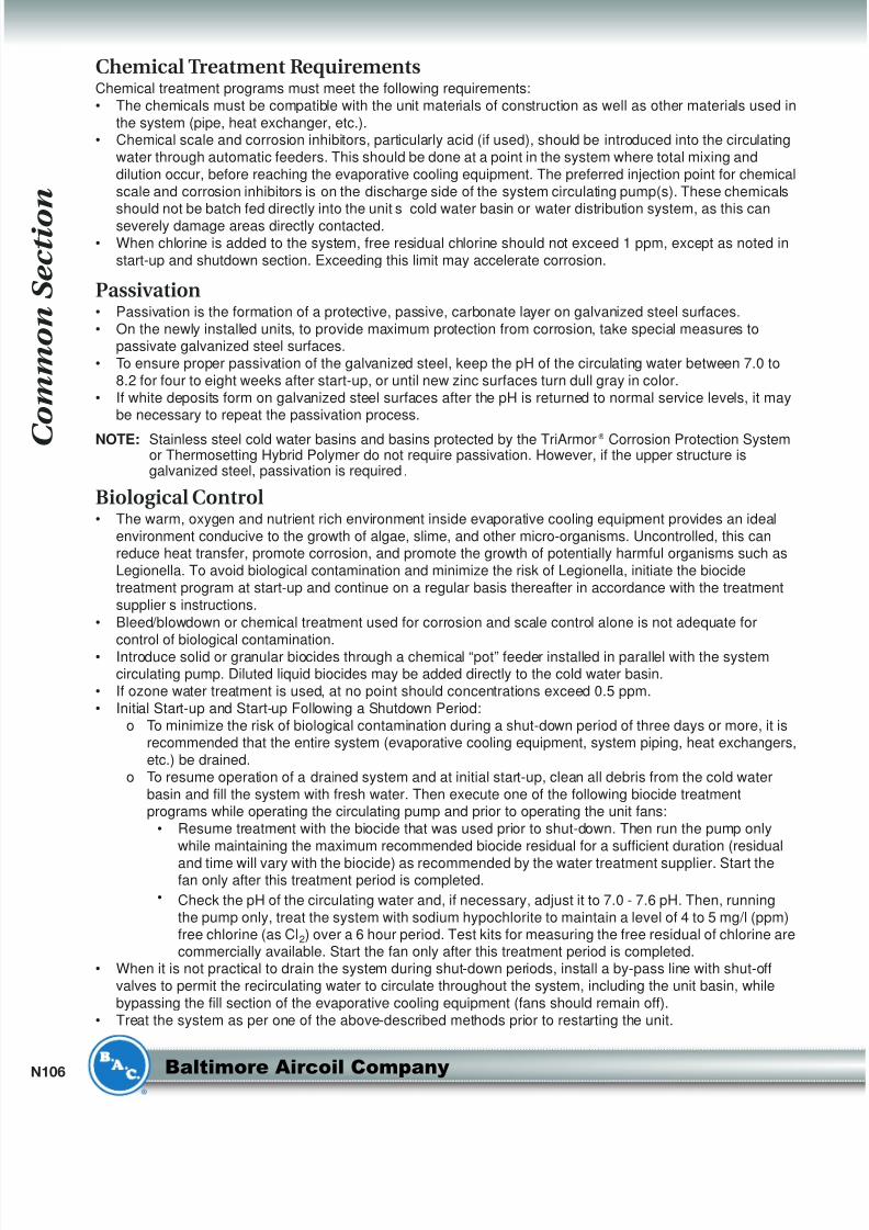
• Keep the chemically treated water within the guidelines given in Table 2. In cases where bleed/blowdown
alone is being employed for corrosion and scale control, without chemical treatment, your water treatmentspecialist may recommend more conservative limits than those shown in Table 2.
Table 2: Quality Guidelines for Chemically Treated Circulating Water
Notes:1. Galvanized steel units require passivation in order to prevent white rust (refer to passivation below).2. Hardness and alkalinity limits may be exceeded under certain circumstances. Consult your water treatment
specialist for recommendations.
3. The conversion factor used to determine conductivity is 0.625 (TDS = 0.625 x Conductivity).
Property of Water Recommended Level
pH 6.5 to 9.0[1]
Hardness as CaCO3 30 to 750 ppm[2]
Alkalinity as CaCO3 500 ppm maximum[2]
Total Dissolved Solids (TDS) 1500 ppm maximum
Conductivity 2400 micromhos[3]
Chlorides250 ppm maximum Cl
(410 ppm maximum as NaCl)
Sulfates 250 ppm maximum
Silica 150 ppm maximum
8/8/2019 Torres Mnto Series v Cto Cerrado
http://slidepdf.com/reader/full/torres-mnto-series-v-cto-cerrado 16/22
C o m m o n S e c t i o n
N106 Baltimore Aircoil Company
Chemical Treatment RequirementsChemical treatment programs must meet the following requirements:
• The chemicals must be compatible with the unit materials of construction as well as other materials used in
the system (pipe, heat exchanger, etc.).• Chemical scale and corrosion inhibitors, particularly acid (if used), should be introduced into the circulating
water through automatic feeders. This should be done at a point in the system where total mixing and
dilution occur, before reaching the evaporative cooling equipment. The preferred injection point for chemical
scale and corrosion inhibitors is on the discharge side of the system circulating pump(s). These chemicals
should not be batch fed directly into the units cold water basin or water distribution system, as this canseverely damage areas directly contacted.
• When chlorine is added to the system, free residual chlorine should not exceed 1 ppm, except as noted in
start-up and shutdown section. Exceeding this limit may accelerate corrosion.
Passivation• Passivation is the formation of a protective, passive, carbonate layer on galvanized steel surfaces.
• On the newly installed units, to provide maximum protection from corrosion, take special measures topassivate galvanized steel surfaces.
• To ensure proper passivation of the galvanized steel, keep the pH of the circulating water between 7.0 to
8.2 for four to eight weeks after start-up, or until new zinc surfaces turn dull gray in color.
• If white deposits form on galvanized steel surfaces after the pH is returned to normal service levels, it maybe necessary to repeat the passivation process.
NOTE: Stainless steel cold water basins and basins protected by the TriArmor ® Corrosion Protection Systemor Thermosetting Hybrid Polymer do not require passivation. However, if the upper structure isgalvanized steel, passivation is required.
Biological Control• The warm, oxygen and nutrient rich environment inside evaporative cooling equipment provides an ideal
environment conducive to the growth of algae, slime, and other micro-organisms. Uncontrolled, this canreduce heat transfer, promote corrosion, and promote the growth of potentially harmful organisms such as
Legionella. To avoid biological contamination and minimize the risk of Legionella, initiate the biocide
treatment program at start-up and continue on a regular basis thereafter in accordance with the treatment
supplier’s instructions.
• Bleed/blowdown or chemical treatment used for corrosion and scale control alone is not adequate for
control of biological contamination.• Introduce solid or granular biocides through a chemical “pot” feeder installed in parallel with the systemcirculating pump. Diluted liquid biocides may be added directly to the cold water basin.
• If ozone water treatment is used, at no point should concentrations exceed 0.5 ppm.
• Initial Start-up and Start-up Following a Shutdown Period:
o To minimize the risk of biological contamination during a shut-down period of three days or more, it isrecommended that the entire system (evaporative cooling equipment, system piping, heat exchangers,
etc.) be drained.
o To resume operation of a drained system and at initial start-up, clean all debris from the cold water
basin and fill the system with fresh water. Then execute one of the following biocide treatmentprograms while operating the circulating pump and prior to operating the unit fans:
• Resume treatment with the biocide that was used prior to shut-down. Then run the pump only
while maintaining the maximum recommended biocide residual for a sufficient duration (residual
and time will vary with the biocide) as recommended by the water treatment supplier. Start thefan only after this treatment period is completed.
• Check the pH of the circulating water and, if necessary, adjust it to 7.0 - 7.6 pH. Then, running
the pump only, treat the system with sodium hypochlorite to maintain a level of 4 to 5 mg/l (ppm)free chlorine (as Cl2) over a 6 hour period. Test kits for measuring the free residual of chlorine arecommercially available. Start the fan only after this treatment period is completed.
• When it is not practical to drain the system during shut-down periods, install a by-pass line with shut-off
valves to permit the recirculating water to circulate throughout the system, including the unit basin, while
bypassing the fill section of the evaporative cooling equipment (fans should remain off).
• Treat the system as per one of the above-described methods prior to restarting the unit.
8/8/2019 Torres Mnto Series v Cto Cerrado
http://slidepdf.com/reader/full/torres-mnto-series-v-cto-cerrado 17/22
N
...because temperature matters
™
System Cleaning
System Cleaning (for Models Series V and Low Profile V (VF1, VFL), HXV, and FXV)With proper precautions, prior to start-up circulate an alkaline solution which can be used to clean condenserwater systems through a closed circuit cooling tower. The necessary precautions include:
• Limit the duration of the cleaning to 1, or at the most 2 days.
• The temperature of the solution should never exceed 100ºF (37.8°C).
• The maximum concentration of chemicals in the circulation solution should not exceed any of the following:o 5% Sodium Hydroxide
o 5% Sodium Metasilicate
o 2% Sodium Carbonate
o 2% Tetra Sodium Pyrophosphateo 0.5% Trisodium Phosphate
o 0.5% Sodium Nitrate
o 5-10% Butyl Cellosolve
Coil Cleaning (for Models Series V and Low Profile V (VF1, VFL), HXV, and FXV)Both the inside and outside of the heat exchange coil may require occasional cleaning. The chemicals used
must be compatible with the materials being treated. For example, the standard coil outside is galvanized
steel. The inside of the coil is black carbon steel. For finned coils, the coil cleaning must be careful not to
damage the fins (outside of the coils) and the coils themselves. For specific recommendations on coil
cleaning, contact a qualified consultant.
Weld Byproduct Cleaning (for Models CXV, VCL, VC1, and VCA)The installation and manufacturing processes commonly used for field assembly of steel-piped systems mayleave weld byproducts inside coils and connecting piping (especially in refrigeration systems). It is common
practice to install filters and/or strainers that remove contaminants during initial system operation. Shortly after
system startup, the filters and/or strainers should be cleaned or replaced.
Water TreatmentA proper water treatment program, administered under the supervision of a competent water treatment
specialist, is an essential part of routine maintenance to ensure the safe operation and longevity ofevaporative cooling equipment, as well as other system components.
Bleed Rate• In evaporative cooling, evaporation of a small portion of the recirculating spray water as it flows through the
equipment causes the cooling effect. As this water evaporates, the impurities originally present remain in
the recirculating water. The concentration of the dissolved solids increases over time and can reach
unacceptable levels.
• In addition, airborne impurities are often introduced into the recirculating water. If these impurities andcontaminants are not effectively controlled, they can cause scaling, corrosion, and sludge accumulations
that reduce heat transfer efficiency and increase system-operating costs, potentially shortening the useful
life of the equipment.
• The degree to which dissolved solids and other impurities build up in the recirculating water may bedefined as the cycles of concentration. Specifically, cycles of concentration is the ratio of the concentration
of dissolved solids (for example - chlorides, sulfates, etc.) in the recirculating water to the concentration of
the same material in the make-up water.
• In order to optimize heat transfer efficiency and maximize equipment life “bleed” or “blowdown” a smallamount of recirculating water from the system. This controls the cycles of concentration to maintain the
quality of the recirculating water within the guidelines given in Table 2, on Page N105.
• Replenish the “bleed” water with fresh make-up water, thereby limiting the build-up of impurities.
8/8/2019 Torres Mnto Series v Cto Cerrado
http://slidepdf.com/reader/full/torres-mnto-series-v-cto-cerrado 18/22
C o m m o n S e c t i o n
N108 Baltimore Aircoil Company
• Bleed/blowdown:o Accomplish the bleed automatically through a solenoid valve controlled by a conductivity meter. The
conductivity meter set point is the water conductivity at the desired cycles of concentration and should
be determined by a competent water treatment expert.
Note: The solenoid valve and conductivity meter must be supplied by others.o Alternatively, use a bleed line with a valve to continuously bleed from the system. In this arrangement,
adjust the rate of bleed using the valve in the bleed line. Measure the rate of bleed by filling a
container of known volume while noting the duration. Check the bleed rate and water quality
periodically to ensure that adequate control of the water quality is being maintained.
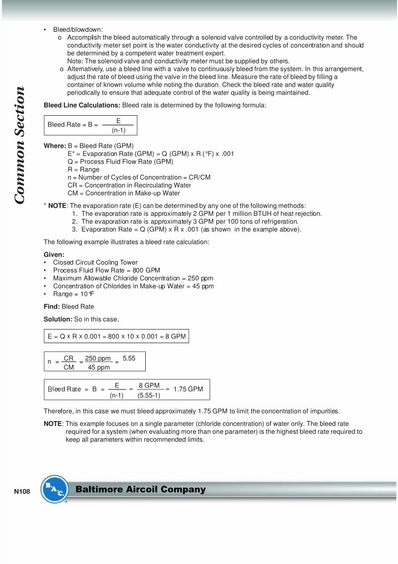
Bleed Line Calculations: Bleed rate is determined by the following formula:
Where: B = Bleed Rate (GPM)
E* = Evaporation Rate (GPM) = Q (GPM) x R (°F) x .001
Q = Process Fluid Flow Rate (GPM)R = Range
n = Number of Cycles of Concentration = CR/CM
CR = Concentration in Recirculating Water
CM = Concentration in Make-up Water
* NOTE: The evaporation rate (E) can be determined by any one of the following methods:
1. The evaporation rate is approximately 2 GPM per 1 million BTUH of heat rejection.
2. The evaporation rate is approximately 3 GPM per 100 tons of refrigeration.3. Evaporation Rate = Q (GPM) x R x .001 (as shown in the example above).
The following example illustrates a bleed rate calculation:
Given:• Closed Circuit Cooling Tower
• Process Fluid Flow Rate = 800 GPM
• Maximum Allowable Chloride Concentration = 250 ppm
• Concentration of Chlorides in Make-up Water = 45 ppm
• Range = 10°FFind: Bleed Rate
Solution: So in this case,
Therefore, in this case we must bleed approximately 1.75 GPM to limit the concentration of impurities.
NOTE: This example focuses on a single parameter (chloride concentration) of water only. The bleed rate
required for a system (when evaluating more than one parameter) is the highest bleed rate required to
keep all parameters within recommended limits.
Bleed Rate = B =E = 8 GPM = 1.75 GPM
(n-1) (5.55-1)
n =CR
=250 ppm
=5.55
CM 45 ppm
E = Q x R x 0.001 = 800 x 10 x 0.001 = 8 GPM
Bleed Rate = B =E
(n-1)
8/8/2019 Torres Mnto Series v Cto Cerrado
http://slidepdf.com/reader/full/torres-mnto-series-v-cto-cerrado 19/22
N
...because temperature matters
™
Basin Heater and Stand Alone Heater Control Panel1
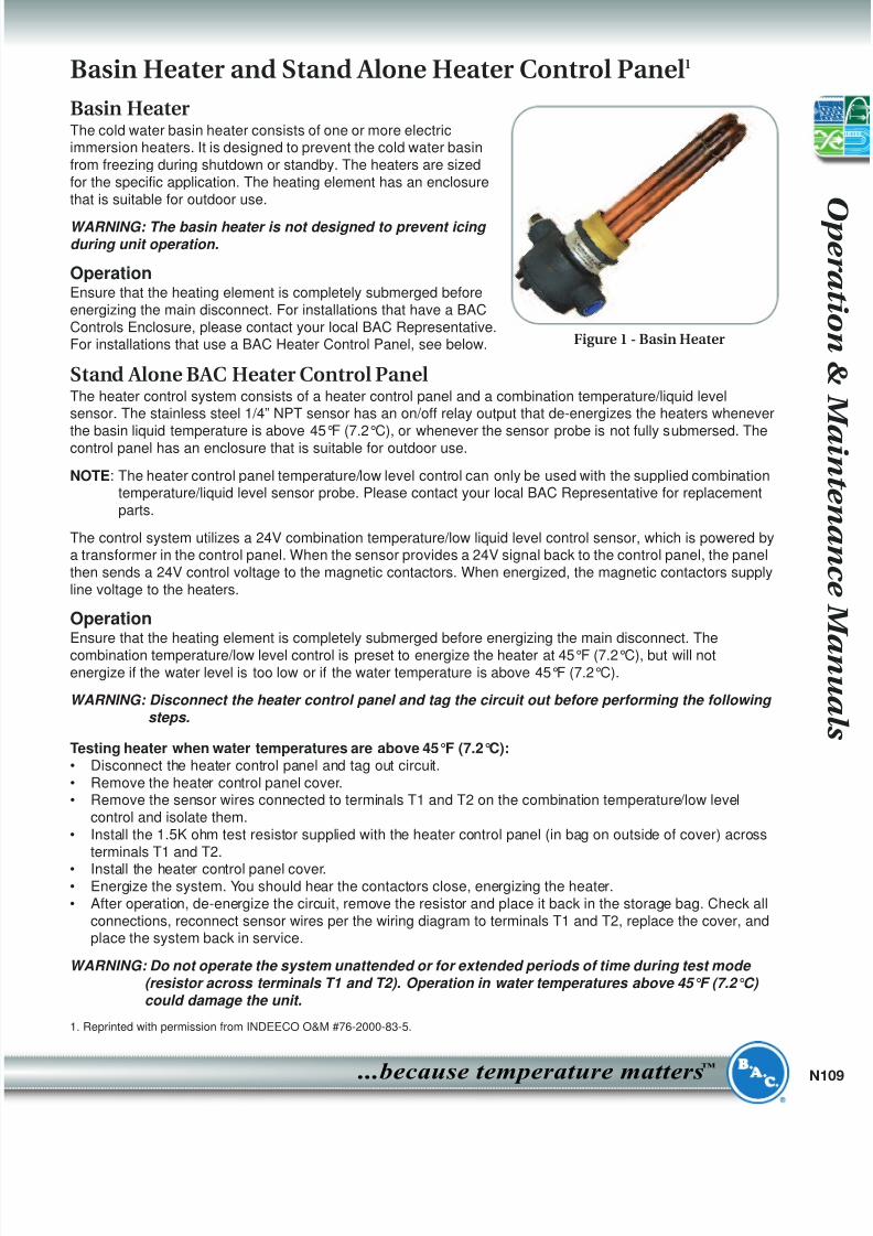
Basin HeaterThe cold water basin heater consists of one or more electricimmersion heaters. It is designed to prevent the cold water basin
from freezing during shutdown or standby. The heaters are sized
for the specific application. The heating element has an enclosure
that is suitable for outdoor use.
WARNING: The basin heater is not designed to prevent icing
during unit operation.
OperationEnsure that the heating element is completely submerged before
energizing the main disconnect. For installations that have a BAC
Controls Enclosure, please contact your local BAC Representative.For installations that use a BAC Heater Control Panel, see below.
Stand Alone BAC Heater Control PanelThe heater control system consists of a heater control panel and a combination temperature/liquid levelsensor. The stainless steel 1/4” NPT sensor has an on/off relay output that de-energizes the heaters whenever
the basin liquid temperature is above 45°F (7.2°C), or whenever the sensor probe is not fully submersed. Thecontrol panel has an enclosure that is suitable for outdoor use.
NOTE: The heater control panel temperature/low level control can only be used with the supplied combinationtemperature/liquid level sensor probe. Please contact your local BAC Representative for replacement
parts.
The control system utilizes a 24V combination temperature/low liquid level control sensor, which is powered bya transformer in the control panel. When the sensor provides a 24V signal back to the control panel, the panel
then sends a 24V control voltage to the magnetic contactors. When energized, the magnetic contactors supply
line voltage to the heaters.
OperationEnsure that the heating element is completely submerged before energizing the main disconnect. The
combination temperature/low level control is preset to energize the heater at 45°F (7.2°C), but will notenergize if the water level is too low or if the water temperature is above 45°F (7.2°C).
WARNING: Disconnect the heater control panel and tag the circuit out before performing the following
steps.
Testing heater when water temperatures are above 45°F (7.2°C):• Disconnect the heater control panel and tag out circuit.
• Remove the heater control panel cover.• Remove the sensor wires connected to terminals T1 and T2 on the combination temperature/low level
control and isolate them.
• Install the 1.5K ohm test resistor supplied with the heater control panel (in bag on outside of cover) across
terminals T1 and T2.
• Install the heater control panel cover.• Energize the system. You should hear the contactors close, energizing the heater.
• After operation, de-energize the circuit, remove the resistor and place it back in the storage bag. Check all
connections, reconnect sensor wires per the wiring diagram to terminals T1 and T2, replace the cover, andplace the system back in service.
WARNING: Do not operate the system unattended or for extended periods of time during test mode
(resistor across terminals T1 and T2). Operation in water temperatures above 45°F (7.2°C)
could damage the unit.
1. Reprinted with permission from INDEECO O&M #76-2000-83-5.
Figure 1 - Basin Heater
8/8/2019 Torres Mnto Series v Cto Cerrado
http://slidepdf.com/reader/full/torres-mnto-series-v-cto-cerrado 20/22
C o m m o n S e c t i o n
N110 Baltimore Aircoil Company
Operation when sensor probe is encased in ice:• De-energize the heater control panel and tag circuit out.
• Remove the heater control panel cover.
• Install a jumper wire across terminals G1 and G2 on the combination temperature/low level control circuit
board.• Install the heater control panel cover.
WARNING: Do not operate the system unattended or for extended periods of time with G1-G2
jumpered. A low liquid level condition could occur and the system will not shut off which
could result in damage to the heater and unit.
• Energize the system and listen for the contactor closing.
• Operate the system until the ice is melted around the probe.• After operation, de-energize the circuit, remove the jumper, check all connections, replace the cover, and
place the system back in service.
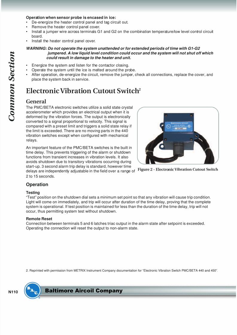
Electronic Vibration Cutout Switch2
GeneralThe PMC/BETA electronic switches utilize a solid state crystalaccelerometer which provides an electrical output when it is
deformed by the vibration forces. The output is electronicallyconverted to a signal proportional to velocity. This signal is
compared with a preset limit and triggers a solid state relay ifthe limit is exceeded. There are no moving parts in the 440
vibration switches except when configured with mechanical
relays.
An important feature of the PMC/BETA switches is the built intime delay. This prevents triggering of the alarm or shutdown
functions from transient increases in vibration levels. It also
avoids shutdown due to transitory vibrations occurring during
start-up. 3 second alarm trip delay is standard, however timedelays are independently adjustable in the field over a range of
2 to 15 seconds.
Operation
Testing“Test” position on the shutdown dial sets a minimum set point so that any vibration will cause trip condition.
Light will come on immediately, and trip will occur after duration of the time delay, proving that the completesystem is operational. If test position is maintained for less than the duration of the time delay, trip will not
occur, thus permitting system test without shutdown.
Remote ResetConnection between terminals 5 and 6 latches triac output in the alarm state after setpoint is exceeded.Operating the connection will reset the output to non-alarm state.
2. Reprinted with permission from METRIX Instrument Company documentation for “Electronic Vibration Switch PMC/BETA 440 and 450”.
Figure 2 - Electronic Vibration Cutout Switch
8/8/2019 Torres Mnto Series v Cto Cerrado
http://slidepdf.com/reader/full/torres-mnto-series-v-cto-cerrado 21/22
N
...because temperature matters
™
Instructions for Installing Field Connections(Equalizer/Bypass/Outlet) on a Cold Water Basin with theTriArmor® Corrosion Protection System
BAC recommends adding a flange connection for field installed equalizers, bypass and outlet connections. Please
order the following supplied prior to unit shutdown.
Table 3: Supplies for Installing Field Connections
1. Use the BAC template provided with the accessory to layout and mark the hole pattern on the exterior of the
cold water basin.
2. Drill a pilot hole from the outside of the cold water basin to the inside of the cold water basin.
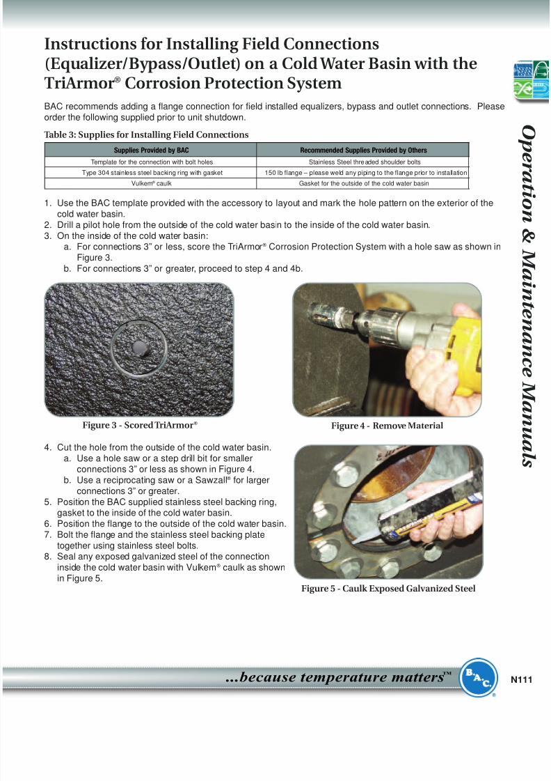
3. On the inside of the cold water basin:a. For connections 3” or less, score the TriArmor ® Corrosion Protection System with a hole saw as shown in
Figure 3.
b. For connections 3” or greater, proceed to step 4 and 4b.
4. Cut the hole from the outside of the cold water basin.
a. Use a hole saw or a step drill bit for smallerconnections 3” or less as shown in Figure 4.
b. Use a reciprocating saw or a Sawzall ® for larger
connections 3” or greater.
5. Position the BAC supplied stainless steel backing ring,gasket to the inside of the cold water basin.
6. Position the flange to the outside of the cold water basin.
7. Bolt the flange and the stainless steel backing plate
together using stainless steel bolts.8. Seal any exposed galvanized steel of the connection
inside the cold water basin with Vulkem ® caulk as shown
in Figure 5.
Figure 3 - Scored TriArmor® Figure 4 - Remove Material
Supplies Provided by BAC Recommended Supplies Provided by Others
Template for the connection with bolt holes Stainless Steel thre aded shoulder bolts
Type 304 stainless steel backing ring with gasket 150 lb flange – please weld any piping to the flange prior to installation
Vulkem ® caulk Gasket for the outside of the cold water basin
Figure 5 - Caulk Exposed Galvanized Steel
8/8/2019 Torres Mnto Series v Cto Cerrado
http://slidepdf.com/reader/full/torres-mnto-series-v-cto-cerrado 22/22
C o m m o n S e c t i o n
Factory Authorized Parts
• Baltimore Aircoil Company maintains a stock of common replacement parts at all times.
• Many BAC Representatives also have BAC replacement parts stocked in their warehouses.• These parts are designed and built specifically for BAC units and assure BAC’s customers of:
o Guaranteed performance
o Immediate availability in most caseso Original equipment quality
o Local assistance with service problems• All factory-authorized parts are guaranteed for 1 year and their use will ensure continued maximum
performance from your BAC equipment.• Parts shipment is normally made within 3 business days after receipt of an order.
• In emergency situations, shipment can usually be made within 24 hours.
• To order factory authorized parts, contact your local BAC Representative. You can locate your local BAC
Representative by the label next to the unit nameplate, by calling (800) 896-8497, or via the Internet atwww.BaltimoreAircoil.com/repfinder. Be sure to include the unit serial number when ordering any parts.
• To facilitate service of your BAC unit, it is suggested that some of the following spare parts be kept on
hand:
o Make-Up Float Ball – large diametero Valve Seat for Make-up Valve – elastomer seat for positive shut off
o Fan Shaft Bearings – grease-lubricated ball bearings with special moisture proof seals and integral
slinger rings designed specifically for evaporative cooler applications.o Fan Belt – solid backed, multi groove, specially compounded, neoprene polyester drive band.o Spray Nozzle and Grommet Kit – large diameter plastic metering nozzles engineered for optimum
water distribution
o Access Door Gasket
o In addition to the repair parts, BAC also offers many retrofit kits designed to enhance safety andaccess, ease of maintenance/operational flexibility and provide additional capacity and capacity
control.
• Finally, your local BAC Representative usually stocks common wear items for immediate delivery, and is
available to inspect your unit to ensure it is in proper operating condition.• Please record your units model number and serial number (as they appear on the unit nameplate) on the
front and back cover. This will help ensure the quickest, most accurate response to your inquiries.


![THE ECOLOGICAL FOOTPRINT OF CAMPO GRANDE … · Instituto de Permacultura Cerrado/ Pantanal (IPCP) [Pantanal Cerrado Permaculture Institute] Secretaria de Desenvolvimento Socioeconômico](https://img.pdfslide.us/doc/110x75/5c10475309d3f20c238c4d7a/the-ecological-footprint-of-campo-grande-instituto-de-permacultura-cerrado.jpg)