Embed Size (px)
Citation preview
ToR on OG System NISCO
Supplemental EIA on OG System
120T Converter Gas Recovery Project
Nanjing Iron & Steel Co., Ltd
April 2005
1
Pub
lic D
iscl
osur
e A
utho
rized
Pub
lic D
iscl
osur
e A
utho
rized
Pub
lic D
iscl
osur
e A
utho
rized
Pub
lic D
iscl
osur
e A
utho
rized
Pub
lic D
iscl
osur
e A
utho
rized
Pub
lic D
iscl
osur
e A
utho
rized
Pub
lic D
iscl
osur
e A
utho
rized
Pub
lic D
iscl
osur
e A
utho
rized
ToR on OG System NISCO
Table of Contents
Chapter 1 General Description…………………………………………………..3
Chapter 2 Main Pollution Source, Pollutant and Control Measures…………11
Chapter 3 Introduction of the New 120t Converter……………………………15
2

ToR on OG System NISCO
Chapter 1 General Description
120 t converter will be installed in the Heavy Plate Mill which is affiliated to
NISCO. See the following attachment for the details of NISCO.
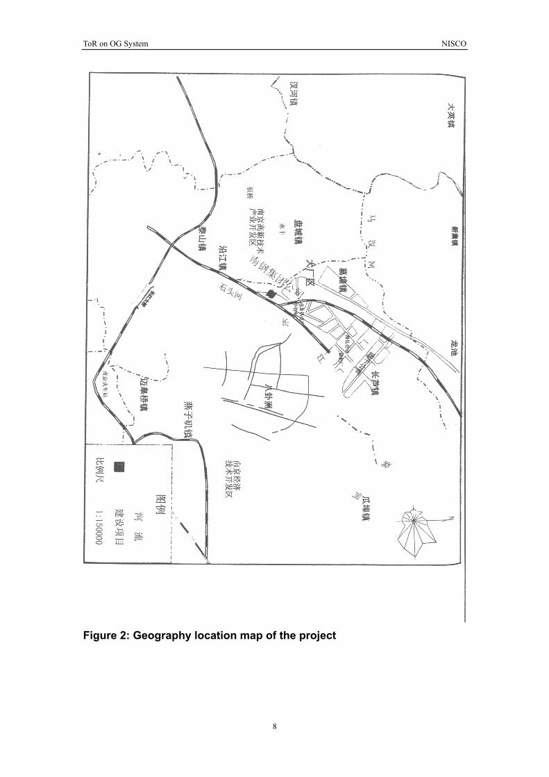
Location:
It is located at DACHANG district, in the north of Nanjing City in a distance of
25 km from the central of the city (the straight-line distance is approximately 16
km). This plant faces the Yangtze River in the South and is close to Ningyang
motor way in the north. In the eastern side it neighbors with Nanjing Thermal
Power Plant, Nanjing Power Plant of North China Energy & Source Co. as well
as Nanjing Chemical Industry Co. The region & location map of NISCO is
shown hereinafter.
Product, output and working staff:
A new 120t top & bottom blown converter will be built with a liquid-steel output
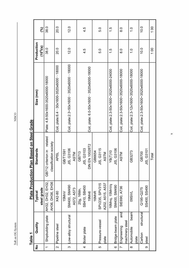
of 1,090,000t/a. The products include on-line sheared plate, plate sheared with
dividing unit and hot rolled coil. The product specification and production
distribution on each steel grade is shown in the following tables.
3
ToR on OG System NISCO
1. General
Nanjing Iron & Steel Co.,Ltd. (hereinafter abb. as NISCO). is a province-level
enterprise group established on the basis of Nanjing Iron & Steel Group Corp.
Ltd. Through the development and construction for more than 40 years, it has
become a large iron & steel complex with a comprehensive productivity of
2,000,000t pig iron, 3,500,000t liquid steel and 4,000,000t steel product. It is
one of the key enterprise groups in Jiangsu province. In 2002, the sales
revenue of NISCO is 14.5 billion Yuan, ranking No. 69 among the “Top 500”
enterprises in China.
Nanjing Steel is located at Jiangbei Industrial Development Area in Nanjing
City along the Yangtze River. It enjoys favorable conditions in transportation. A
special railway is provided in plant area which is connected with
Beijing-Shanghai railway. An available 5000-ton plant-owned pier at Yangtze
River can provide convenience for loading/unloading.
In 2002, steel output of NISCO is 2,532,000t, the pig iron is 1,886,000t. The
profit & tax realized is 750 mil Yuan, in which the profit is 410 mil Yuan. In the
end of 2004, the original value of fixed assets is 3.75 billion Yuan and the net
value is 2.01 Yuan. The main product is medium or small sized section steel
and wire/rod, heavy plate, pack rolling sheet and steel strip, etc. All the steel
products are of carbon steel and low-alloy structure steel except the heavy
plate which are used as ship-building plate and boiler plate.
The configuration of existing production system
In coking, sintering and iron-making system there are two 42-battery coke
ovens with productivity of 580,000 t/a; two 39m2 sintering machines and two
24m2 sintering machines with productivity of 2,500,000 t/a; two oxidized pellet
shaft furnaces with the productivity of 800,000 t/a, one 300m3 blast furnace
and four 350m3 blast furnaces with the productivity of 1,850,000 t/a.
In steel-making plant there are three 20t BOF converters with the productivity
4
ToR on OG System NISCO
of 1,700,000 t/a; one 70t ultra high power EAF and one ladle refining furnace
with the productivity of 700,000 t/a; one R6m 4-strand billet caster, one
R5.25m 5-strand billet caster, one R5.7-21m ultra lower-head single-strand
slab caster, and R8m 5-strand billet caster with a total productivity of 1,700,000
t/a.
In steel-rolling system there are one medium-sized blooming mill with
productivity of 400,000 t/a, three small-sized section mill, wire / rod mill, heavy
plate mill, steel sheet mill, strip mill per each with the rolling productivity of
2,600,000 t/a. in NISCO a complete quality assurance system has already
been built up and successfully certified with IS09000 and ISO 2000 quality
system. The products namely thread steel, medium plate and high wire rod
were awarded with “Gold Cup Prize”.
In August 8, 2004, Nanjing Iron & Steel Complex Ltd. was established based
on the joint-venture between NISCO and Shanghai Fuxing Group. It indicates
that NISCO has been transformed from a pure state-owned enterprise to a non
state-owned enterprise.. During the “tenth five-year plan” period, NISCO plans
to invest twelve billion Yuan in technical updating for maximization and
modernization. Now a “wide medium plate (coil) project” and its associated
project has been implemented which will need investment of more than seven
billions Yuan to readjust the product structure. This project has been approved
by the State Council, and will be recorded as the one with the biggest
investment so far in the history of NISCO and Nanjing area in the field of
industry. After the commissioning of the project (in the third quarter of 2005 as
per schedule), the productivity of plate (coil) per year will be up to 1,500,000 t.
We also decide to build another plate production line recently by utilizing the
fund through joint-venture combined with bank loan, in order to gain an
additional steel output of 2,000,000t. The commissioning of this production line
is expected to be finished at the beginning of 2006. Till then the total
production capacity including the existing plant and the new production line will
5

ToR on OG System NISCO
be up to 6,500,000 t. Through the capital-fund operation and involvement in
the asset regroup with other steel mill at home and abroad, the productivity will
be approximately 6,000,000 t~7,000,000t under the investment and share
holding. By 2010, NISCO will reach the productivity of 15,000,000t in steel and
fifty billions Yuan in sales revenue.
6
ToR on OG System NISCO
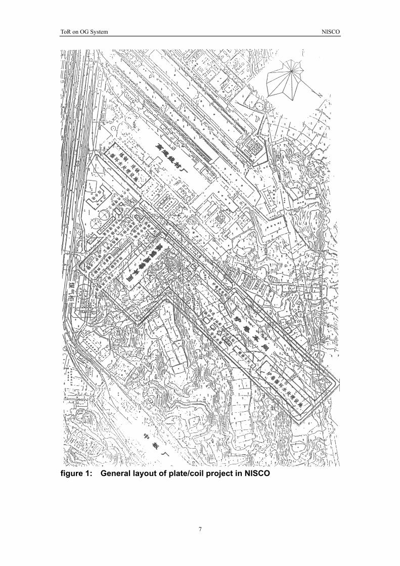
figure 1: General layout of plate/coil project in NISCO
7
8
Figure 2: Geography location map of the project
ToR on OG System NISCO
ToR
on
OG
Sy
stem
NIS
CO
9
Tabl
e 1
Plat
e Pr
oduc
tion
Plan
Bas
ed o
n St
eel G
rade
N
o Q
ualit
yTy
pica
l st
eel g
rade
St
anda
rds
Si
ze (m
m)
Pr
oduc
tion
(104 t/a
)
(%)
1 S
hipb
uild
ing
plat
e A
H32
, DH
32, E
H32
,A
H36
, DH
36, E
H36
GB
712
crite
rion
in
rela
ted
clas
sific
atio
n so
ciet
y P
late
: 4.8
-50x
1600
-352
0x60
00-1
8000
38
.0
38.0
2 P
ipel
ine
stee
l
X42
-80
AP
l5L
Coi
l, pl
ate:
6.4~
30x1
600-
3520
x600
0~18
000
20.0
20
.0
3
Low
-allo
y st
ruct
ural
15
MnV
S
M40
0, S
M49
0 A
572,
A57
3
GB
/T15
91
JlS
, G31
06
AS
TM
Coi
l, pl
ate:
2.3~
50x1
600~
3520
x600
0~18
000
12
.0
12
.0
4
Boi
ler p
late
20
g, 1
6Mn,
S
B41
0, S
B45
0 19
Mn6
GB
713
JIS
, G31
03
DlN
EN
100
28T2
4.
5
4.
5
5
Pre
ssur
e-ve
ssel
pl
ate
16M
nR
SP
V23
5, S
PV
315
A20
2, A
515,
A53
7
GB
6654
JI
S, G
3115
A
STM
Coi
l, pl
ate:
6.0
-50x
1600
~35
20x6
000-
1800
0
5.
0
5.
0
6 B
ridge
-bea
m p
late
16
Mnq
, 15M
nVq
SM
400,
SM
490
YB
(T)1
0 JI
S, G
3106
C
oil,
plat
e:2.
3-50
x160
0~35
20x6
000-
2400
0 1.
5
1.5
7 E
ngin
eerin
g an
d m
achi
nery
ste
el
StE
690,
A73
6 A
STM
C
oil,
plat
e:2.
3-50
x160
0~35
20x6
000-
1800
0 8.
0 8.
0
8 A
utom
obile
be
am
plat
e 09
SiV
L G
B32
73
Coi
l, pl
ate:
2.3-
12x1
600~
3520
x600
0-18
000
1.0
1.0
9 C
arbo
n st
ruct
ural
st
eel
Q19
5~Q
275
SS
400,
SS
490
GB
700
JIS
, G31
01
Coi
l, pl
ate:
2.3-
50x1
600~
3520
x600
0-18
000
10.0
10
.0
To
tal
1 00
1
00

ToR on OG System NISCO
Table 2:
Product variety and specification No. Product variety Percentage
(%) Specification
1
Hot-rolled steel plate
~75
Thickness: 4.8-50mm Width: 1600~3520mm Length: 6000-24000mm
2
Hot-rolled steel coil
~25
Thickness: 2.3-20mm Width: 1600~2800mm Unit weight of coil: 20.5kg/mm Coil weight: ~45t(max)
10
ToR on OG System NISCO
Chapter 2 Main pollution source, pollutant and control measures
2.1 Main pollution source and main pollutant
Primary fume containing dust and CO is generated during converter
melting process
SS contained waste water is produced during wet-gas cleaning
process of converter
Sludge collected from waste water coming from converter-gas
scrubbing system
Noise produced by pump, motor, etc. during operation.
2.2 Pollution control measures and results
2.2.1 Fume-emission control
Passing through furnace mouth and fume hood, the primary fume
generated in converter smelting will enter into evaporated cooling
duct. After cooled and cleaned by two-stage Venturi tube as well as
de-watered by dehydrator, it will be discharged via 47m stack. The
dust content is lower than 120mg/Nm3, which is in compliance with
the criteria of category 3 (criteria of emission:150 mg/Nm3) specified
in Criteria for Air Pollutant Emitted from Industrial Furnace/Kiln .
During emission, in case that CO content in fume is high, the ignition
device on top of stack will be ignited automatically to make CO in
fume into CO2 through combustion.
2.2.2 Treatment of waste water
The total water consumption is 629m3/h and the make up water is
80m3/h.The reusing rate of water is 80%. The method of “using
indirect cooling water to make up direct cooling water” and series
arrangement will be adopted in production process.
11

ToR on OG System NISCO
The indirect cooling water is mainly used for 2-stage Venturi tube
jacket and fan, with only a water temperature rise and no
contamination. The water will be recirculated and cooled through
cooling tower and reused in direct cooling system and other system. A
little amount of ~32 m3/h non-pressure waste water will be discharged.
The discharged waste water is in accordance with criteria of category
1 (SS content=70 mg/L) specified in Criteria for Waste Water
Discharge in Steel Industry.
The direct cooling water system mainly contains the water from gas
scrubbing system. The waste water will be reused after thickened in
vertical sediment basin, cooled in cooling tower and pressurization,
and has no water to be discharged. The slurry discharged from the
bottom of sediment basin will under through dehydration treatment in
board-frame filer press.
12

ToR on OG System NISCO
2.2.3 Solid waste treatment and overall utilization
The slurry produced from wet purification system of converter fume is
pressed into slurry cake with the board-frame filter press. The main
composition is ferro- oxide which will be used for material proportion
in sintering plant.
2.2.4 Noise control
The fan is installed in an separate room for sound proof. Flexible
connection will be adopted at the inlet and outlet of fan and in
between the pipes.
Hydraulic pump will be installed in a separate room sound isolation.
After adopted the above-mentioned measure of sound insulation,
noise reduction and distance attenuation, the noise level at the plant
boundary can be maintained as before.
The main pollution source and main pollutant for this project are
shown in table 3.
Table 3 Main Pollution Source and Main Pollutant
No. Pollutant Control measure Emission/discharge/level 1
Dust-laden fume
Emitted through high stack afterdedusting by 2-stage Venturitube
emission amount:23.1t/a Emission intensity: ≤120 mg/Nm3
2
Waste water
SS<70mg/L
Non-pressure net waste water discharged outside :32m3/h, 208,000 m3/a.
2 Slurry cake Used for proportioning insintering plant
3 Noise of fan Sound proof inside workshopand distance attenuation.
4 Noise of Sound proof inside workshopand distance attenuation. hydraulic pump
13

ToR on OG System NISCO
2.3 Environment monitoring & the management organization of environmental protection
The environmental management department will take the
responsibility for the work of environment control and monitoring in
this project.
(1) 3x20t existing converter steel-making process flow chart and
sewage production points
14

ToR on OG System NISCO
Scrap Hot Metal Bulk Material, Ferroalloy
Exhaust stack
Bag Filter
Secondary Waste Refractory 3X20t Converter fume
Filtered dust
Primary fume Liquid steel SlagReturn to sinter for
burdening (Burnt to emission)
Exhaust stack
fume fume BOF-gas fan house
OG System Waste w
ater after treatment
Waste
water
Slurry Treating in vertical
settling tank
Waste w
ater
Thickener
De-watered mud cake
Cooling tower OG slurry de-water
then to sinter plant for
burdening
OG system includes:(Treatment in vertical settling tank)
Converter fume from evaporation cooling duct→Stage-1 overflow
Venturi→Stage-1 impact-type gravity dewaterer→Stage-2 Venturi with annular
gap adjustable throat→Stage-2 900 elbow dewaterer→ cyclone dewaterer
Fig 1 Process flow chart of 30t BOF and pollutant source
15
ToR on OG System NISCO
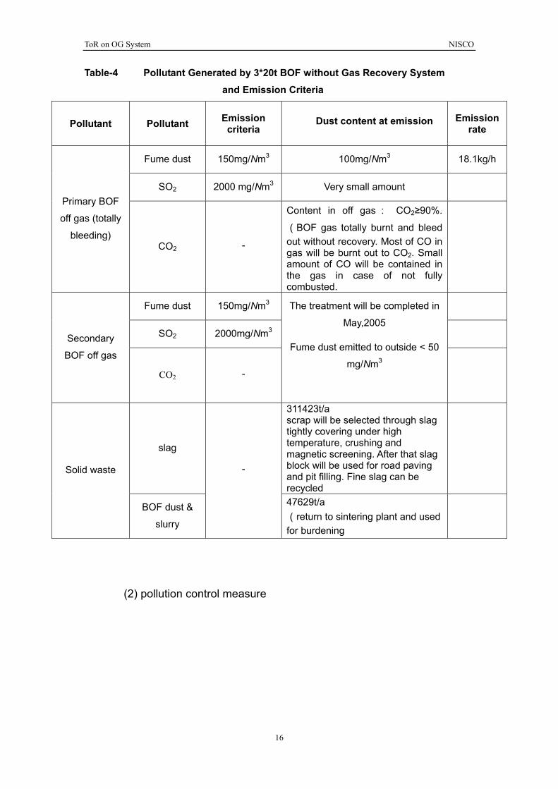
Table-4 Pollutant Generated by 3*20t BOF without Gas Recovery System and Emission Criteria
Pollutant Pollutant Emission criteria
Dust content at emission Emission rate
Fume dust 150mg/Nm3 100mg/Nm3 18.1kg/h
SO2 2000 mg/Nm3 Very small amount Primary BOF
off gas (totally
bleeding) CO2 -
Content in off gas: CO2≥90%.
(BOF gas totally burnt and bleed out without recovery. Most of CO in gas will be burnt out to CO2. Small amount of CO will be contained in the gas in case of not fully combusted.
Fume dust 150mg/Nm3
SO2 2000mg/Nm3 Secondary
BOF off gas
CO2 -
The treatment will be completed in
May,2005
Fume dust emitted to outside < 50
mg/Nm3
slag
311423t/a scrap will be selected through slag tightly covering under high temperature, crushing and magnetic screening. After that slag block will be used for road paving and pit filling. Fine slag can be recycled
Solid waste
BOF dust &
slurry
-
47629t/a (return to sintering plant and used for burdening
(2) pollution control measure
16
ToR on OG System NISCO
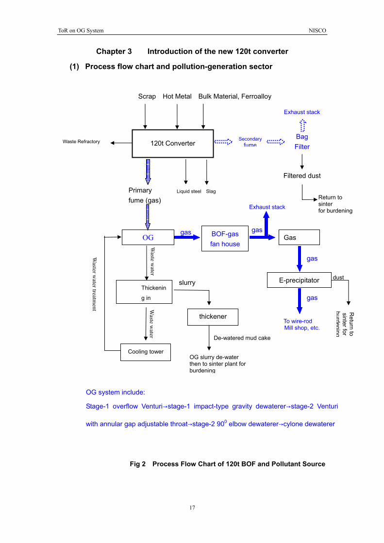
Chapter 3 Introduction of the new 120t converter
(1) Process flow chart and pollution-generation sector
Scrap Hot Metal Bulk Material, Ferroalloy
Exhaust stack
Bag Filter
Secondary fume120t Converter Waste Refractory
Filtered dust
Primary fume (gas)
Liquid steel SlagReturn to sinter Exhaust stack for burdening
gas gas BOF-gas fan house
OG Gas W
aste water
gas Waster w
ater treatment
dust E-precipitator slurry Thickenin
g in gas
Waste w
ater
Return to
sinter for burdening
thickener To wire-rod Mill shop, etc.
De-watered mud cake
Cooling tower OG slurry de-water then to sinter plant for burdening
OG system include:
Stage-1 overflow Venturi→stage-1 impact-type gravity dewaterer→stage-2 Venturi
with annular gap adjustable throat→stage-2 900 elbow dewaterer→cylone dewaterer
Fig 2 Process Flow Chart of 120t BOF and Pollutant Source
17
ToR on OG System NISCO
18
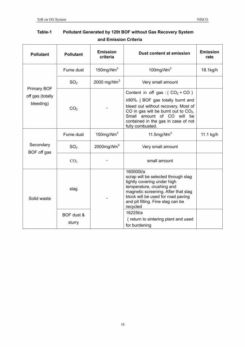
Table-1 Pollutant Generated by 120t BOF without Gas Recovery System and Emission Criteria
Pollutant Pollutant Emission criteria
Dust content at emission Emission rate
Fume dust 150mg/Nm3 100mg/Nm3 18.1kg/h
SO2 2000 mg/Nm3 Very small amount Primary BOF
off gas (totally
bleeding) CO2 -
Content in off gas:(CO2+CO)≥90%.(BOF gas totally burnt and bleed out without recovery. Most of CO in gas will be burnt out to CO2. Small amount of CO will be contained in the gas in case of not fully combusted.
Fume dust 150mg/Nm3 11.5mg/Nm3 11.1 kg/h
SO2 2000mg/Nm3 Very small amount Secondary
BOF off gas
CO2 - small amount
slag
160000t/a scrap will be selected through slag tightly covering under high temperature, crushing and magnetic screening. After that slag block will be used for road paving and pit filling. Fine slag can be recycled
Solid waste
BOF dust &
slurry
-
16225t/a (return to sintering plant and used for burdening
N
ISC
O
19
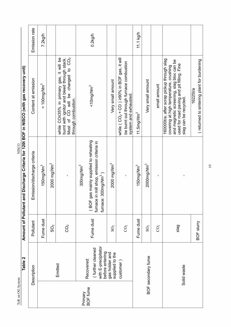
Tabl
e 2
A
mou
nt o
f Pol
luta
nt a
nd D
isch
arge
Crit
eria
for 1
20t B
OF
in N
ISC
O (w
ith g
as re
cove
ry u
nit)
ToR
on
OG
Sys
tem
Des
crip
tion
P
ollu
tant
E
mis
sion
/dis
char
ge c
riter
ia
Con
tent
at e
mis
sion
E
mis
sion
rate
Fum
e du
st
150m
g/N
m3
< 10
0mg/N
m3
7.2k
g/h
SO
2 20
00 m
g/N
m3
Em
itted
CO
2 -
whi
le C
O≤3
5% i
n pr
imar
y ga
s, i
t w
ill be
bu
rnt w
ith ig
nito
r and
ble
ed th
roug
h st
ack.
M
ost
of
CO
w
ill be
ch
ange
d to
C
O2
thro
ugh
com
bust
ion.
Fum
e du
st
300m
g/N
m3
(B
OF
gas
mai
nly
supp
lied
to re
heat
ing
furn
ace
in m
ill sh
op, e
mis
sion
crit
eria
in
furn
ace:
300
mg/N
m3 )
<10m
g/N
m3
0.2k
g/h
SO2
2000
mg/N
m3
Very
sm
all a
mou
nt
Prim
ary
BO
F fu
me
R
ecov
ered
:
(fu
rther
cle
aned
w
ith E
-pre
cipi
tato
r be
fore
ent
erin
g ga
s ho
lder
and
su
pplie
d to
the
cust
omer)
C
O2
-
whi
le(
CO
2+C
O)≥9
0% in
BO
F ga
s, it
will
be b
urnt
out
thro
ugh
furn
ace
com
bust
ion
syst
em a
nd e
xhau
sted
.
Fum
e du
st
150m
g/N
m3
11
1.1
kg/
h .5
mg/N
m3
1
SO2
2000
mg/N
m3
Very
sm
all a
mou
nt
B
OF
seco
ndar
y fu
me
CO
2 -
sm
all a
mou
nt
slag
1600
00t/a
; afte
r scr
ap p
icku
p th
roug
h sl
ag
cove
ring
at h
igh
tem
pera
ture
, cru
shin
g an
d m
agne
tic s
cree
ning
, sla
g bl
oc c
an b
e us
ed fo
r roa
d pa
ving
and
pit
fillin
g. F
ine
slag
can
be
recy
cled
.
S
olid
was
te
BO
F sl
urry
-
1622
5t/a
(
retu
rned
to s
inte
ring
plan
t for
bur
deni
ng
ToR on OG System NISCO
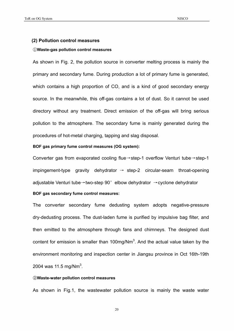
(2) Pollution control measures
①Waste-gas pollution control measures
As shown in Fig. 2, the pollution source in converter melting process is mainly the
primary and secondary fume. During production a lot of primary fume is generated,
which contains a high proportion of CO, and is a kind of good secondary energy
source. In the meanwhile, this off-gas contains a lot of dust. So it cannot be used
directory without any treatment. Direct emission of the off-gas will bring serious
pollution to the atmosphere. The secondary fume is mainly generated during the
procedures of hot-metal charging, tapping and slag disposal.
BOF gas primary fume control measures (OG system):
Converter gas from evaporated cooling flue→step-1 overflow Venturi tube→step-1
impingement-type gravity dehydrator → step-2 circular-seam throat-opening
adjustable Venturi tube→two-step 90°elbow dehydrator →cyclone dehydrator
BOF gas secondary fume control measures:
The converter secondary fume dedusting system adopts negative-pressure
dry-dedusting process. The dust-laden fume is purified by impulsive bag filter, and
then emitted to the atmosphere through fans and chimneys. The designed dust
content for emission is smaller than 100mg/Nm3. And the actual value taken by the
environment monitoring and inspection center in Jiangsu province in Oct 16th-19th
2004 was 11.5 mg/Nm3.
②Waste-water pollution control measures
As shown in Fig.1, the wastewater pollution source is mainly the waste water
20

ToR on OG System NISCO
generated from gas scrubbing system (OG system) during the wet cleaning for the
primary gas of the converter.
This water is polluted by the fume dust. First it flows into the thickening pool through
an elevated groove. Water after thickening is pressurized by the pump before being
sent to cooling tower. The cooled-down water is recycled in the dedusting equipment.
③solid-waste treatment
As shown in Fig.1, the main solid waste from converter process is steel slag,
converter sludge and refractory waste.
After keeping at high temperature, crashing and magnetic dressing, the scrap is
taken away from slag. The slag lump is used to pave roads and fill pits, while the slag
powder can be recycled.
The slurry from gas scrubbing system will first enter the slurry pool. And then it is
pumped with pressure to slurry clarifier. After that the slurry in the bottom is sent to
plate and frame filter to be dewatered. The left is converter sludge. Generally the
converter sludge will be sent back to sintering plant and be reused in burdening.
The refractory waste mainly arises from the abandoned refractory material when the
converter is relined or repaired, the main component of which is silicon oxide and
aluminum oxide. The agglomerated and castable refractory waste can be used as
normal construction material, or after pulverization, be used to produce refractory
bricks. The smashes and crushes can be used to pave roads and fill pits.
According to the provisions about solid waste category in Guideline for Solid Waste
21
ToR on OG System NISCO
Declaring Registration made by State Environmental Protection Administration,
converter slag belongs to normal industrial solid waste. And converter sludge and
refractory waste belong to other waste. Converter melting process does not generate
poisonous waste.
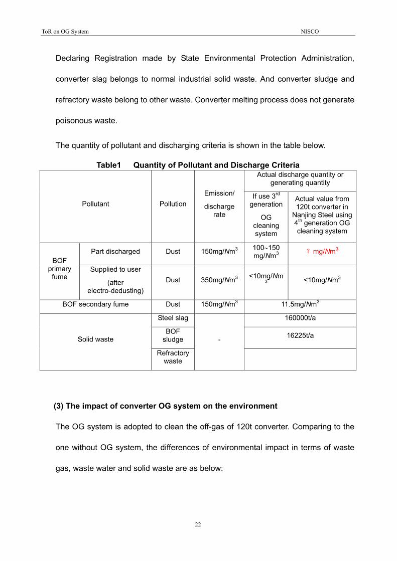
The quantity of pollutant and discharging criteria is shown in the table below.
Table1 Quantity of Pollutant and Discharge Criteria Actual discharge quantity or
generating quantity
Pollutant Pollution Emission/
discharge rate
If use 3rd generation
OG cleaning system
Actual value from 120t converter in
Nanjing Steel using 4th generation OG cleaning system
Part discharged Dust 150mg/Nm3 100∼150 mg/Nm3 ?mg/Nm3
BOF primary fume
Supplied to user
(after electro-dedusting)
Dust 350mg/Nm3 <10mg/Nm3 <10mg/Nm3
BOF secondary fume Dust 150mg/Nm3 11.5mg/Nm3
Steel slag 160000t/a
BOF sludge 16225t/a Solid waste
Refractory waste
-
(3) The impact of converter OG system on the environment
The OG system is adopted to clean the off-gas of 120t converter. Comparing to the
one without OG system, the differences of environmental impact in terms of waste
gas, waste water and solid waste are as below:
22
ToR on OG System NISCO
①waste gas
The converter gas, which is not purified by the OG system, will have a dust content
up to 100~150g/Nm3. This gas will bring serious pollution to the atmosphere through
direct emission. However, the one that is purified by the OG system will have dust
content lower than 100 mg/Nm3.
②waste water
The converter steel-making process with OG system will generate the off-gas
scrubbing water as shown in part ② paragraph (2). This water has been
contaminated by the gas dust, so it needs water treatment such as thickening and
cooling. But it still can be recycled after treatment.
③solid waste
The converter steel-making process with OG system will generate sludge during gas
scrubbing, as shown in part ③ paragraph (2). However, generally this part of
converter sludge can be reused in burdening for sinter process.
The pollution affecting operator’s health during converter production is mainly the
breathable particles. According to the results of monitoring and inspection made by
the environment control station of Nanjing Steel in December 2004, since Nangang’s
newly built 120t converter adopts effective control measures to primary and
secondary off-gas, the atmosphere dust content (as 5.6 mg/Nm3) in every post meets
the criteria of harmful factors (8 mg/Nm3) for Job Contact (GBZ2-2002) in working
site.
23
ToR on OG System NISCO
(4) Implementing schedule
The construction of converter OG system started in May 2002. After two - year
construction, it was completed and put into production in June 2004.
(5) Cost evaluation
The total investment of 120t converter OG system is 43.8362 million yuan, including
OG system as 3.9034 million yuan, BOF gas fan room as 11.9789 million yuan and
storage and distribution station as 27.9539 million yuan.
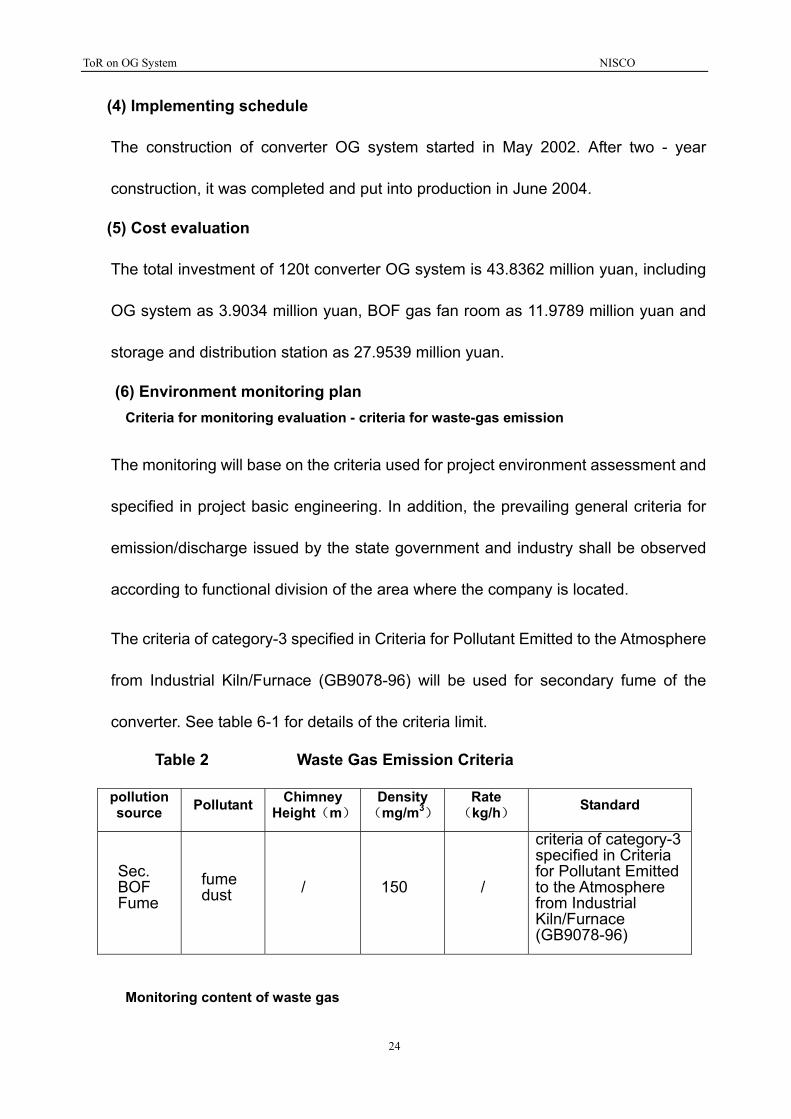
(6) Environment monitoring plan � Criteria for monitoring evaluation - criteria for waste-gas emission
The monitoring will base on the criteria used for project environment assessment and
specified in project basic engineering. In addition, the prevailing general criteria for
emission/discharge issued by the state government and industry shall be observed
according to functional division of the area where the company is located.
The criteria of category-3 specified in Criteria for Pollutant Emitted to the Atmosphere
from Industrial Kiln/Furnace (GB9078-96) will be used for secondary fume of the
converter. See table 6-1 for details of the criteria limit.
Table 2 Waste Gas Emission Criteria
pollution source Pollutant Chimney
Height(m)Density
(mg/m3)Rate
(kg/h) Standard
Sec. BOF Fume
fume dust / 150 /
criteria of category-3 specified in Criteria for Pollutant Emitted to the Atmosphere from Industrial Kiln/Furnace (GB9078-96)
� Monitoring content of waste gas
24
ToR on OG System NISCO
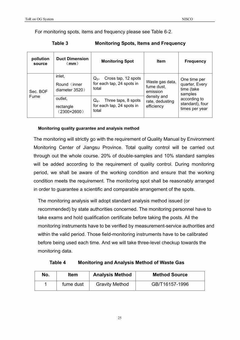
For monitoring spots, items and frequency please see Table 6-2.
Table 3 Monitoring Spots, Items and Frequency
pollution source
Duct Dimension (mm) Monitoring Spot Item Frequency
inlet,
Round(inner diameter 3520)
Q3, Cross tap, 12 spots for each tap, 24 spots in total
Sec. BOF Fume outlet,
rectangle(2300×2600)
Q4, Three taps, 8 spots for each tap, 24 spots in total
Waste gas data, fume dust, emission density and rate, dedusting efficiency
One time per quarter, Every time (take samples according to standard), four times per year
� Monitoring quality guarantee and analysis method
The monitoring will strictly go with the requirement of Quality Manual by Environment
Monitoring Center of Jiangsu Province. Total quality control will be carried out
through out the whole course. 20% of double-samples and 10% standard samples
will be added according to the requirement of quality control. During monitoring
period, we shall be aware of the working condition and ensure that the working
condition meets the requirement. The monitoring spot shall be reasonably arranged
in order to guarantee a scientific and comparable arrangement of the spots.
The monitoring analysis will adopt standard analysis method issued (or
recommended) by state authorities concerned. The monitoring personnel have to
take exams and hold qualification certificate before taking the posts. All the
monitoring instruments have to be verified by measurement-service authorities and
within the valid period. Those field-monitoring instruments have to be calibrated
before being used each time. And we will take three-level checkup towards the
monitoring data.
Table 4 Monitoring and Analysis Method of Waste Gas
No. Item Analysis Method Method Source
1 fume dust Gravity Method GB/T16157-1996
25

ToR on OG System NISCO
26
Note: Both parties agree that the figure with question mark in the table will be provided at the end of March.