Embed Size (px)
Citation preview
Tool Classification Report Page 1 Version 0.8
Tool Classification Report for Testwell CTC++ Chain
Version 0.8
Version: 0.8
Date: 2014-11-17
Status: Generic / Adapted / Presented / Generated / Reviewed / Final
Author: Dr. Oscar Slotosch
File: TCR_ManualPart.docx
Size: 34 Pages
Tool Classification Report Page 2 Version 0.8
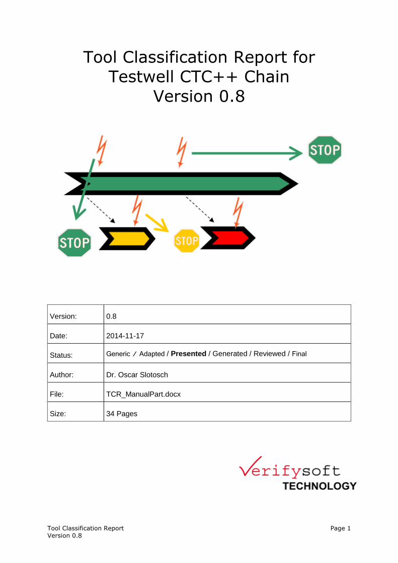
Revision History:
Version Date Status Author Change
0.1 2012-09-12 Generic Slotosch Template created
0.2 2013-10-10 Adapted Slotosch Adapted to Testwell CTC++ Chain
0.3 2014-01-23 Presented R. Bär Reviewed from Verifysoft
0.4 2014-01-30 Reviewed Slotosch Embedded fonts as review feedback
0.8 <generation date>
Generated Generator Tool
Filled model-dependent parts
0.9 <review date>
Reviewed <Customer> Reviewed and updated
1.0 <finalization date>
Final <Customer> Finalized document
Tool Classification Report Page 3 Version 0.8
Contents
1 Scope of this Document .............................................................................................. 4
2 Glossary ....................................................................................................................... 5
3 Evaluation Method ....................................................................................................... 6
3.1 Standard Requirements .............................................................................................. 9 3.1.1 ISO 26262 Requirements ..................................................................................... 11
3.1.1.1 Planning Tool Usage .................................................................................... 12 3.1.1.2 Tool Evaluation ............................................................................................ 12
3.1.1.3 Tool Qualification ........................................................................................ 13 3.1.1.4 Validity Check .............................................................................................. 14 3.1.1.5 Compliance Check and Confirmation Review ............................................. 14
3.1.2 IEC 61508 ............................................................................................................ 14
3.1.3 DO-178 C and DO-330 ........................................................................................ 15 3.1.4 EN 50128 .............................................................................................................. 16
3.2 Tool Chain Analysis Method ................................................................................... 17
3.2.1 Define List of Tools ............................................................................................. 17 3.2.2 Gather tool application facts and identify use cases............................................. 17 3.2.3 Determine Tool Impact ........................................................................................ 18 3.2.4 Identify Potential Errors ....................................................................................... 18
3.2.4.1 Black Box Error Identification Strategy:...................................................... 18 3.2.4.2 White box Error Identification Strategy: ...................................................... 19
3.2.4.3 Consolidating Potential Errors: .................................................................... 19 3.2.5 Identify and Assign Checks and Restrictions ....................................................... 20 3.2.6 Compute the Tool Confidence Level ................................................................... 20
3.2.7 Document the evaluation results .......................................................................... 21 3.2.7.1 TI Determination .......................................................................................... 21
3.2.7.2 TCL Determination ...................................................................................... 21 3.3 Model Creation and Extension: Tool Chain Analyzer Tool .................................... 22
3.3.1 Modeling .............................................................................................................. 23 3.3.2 Validation ............................................................................................................. 24 3.3.3 Review .................................................................................................................. 25 3.3.4 Report generation ................................................................................................. 26
3.4 Model Application: Qualification Support Tool ...................................................... 30
4 Tool Chain Definition ................................................................................................. 30
5 Tool Impact Determination ........................................................................................ 31
6 [generated] ................................................................................................................. 33
7 References ................................................................................................................. 34
Tool Classification Report Page 4 Version 0.8
1 Scope of this Document
This document is a results report of classifying used tools according to their confidence need during the use of a SW tool chain or parts of a
software tool chain related to a specific tool, e.g. a “Generating Tool Chain”.
The evaluated tool chain Testwell CTC++ Chain is used by <Customer> for software development. The content of this document consists of 4
parts:
1. General description of the evaluation method (see section 3).
2. Definition of the tool chain being evaluated (see section 4). 3. Determination of tool impact (see section 5).
4. Determination of tool confidence (see section 6).
The classification is compatible to ISO26262s tool confidence levels but can also be used in other standards (IEC 61508, DO-330, EN 50128) since
they require to determine the confidence needs for the tools by analyzing the impact of potential tool errors. A detailed tracing of the requirements
are in the tool qualification plans for the tools with qualification need
Tool Classification Report Page 5 Version 0.8
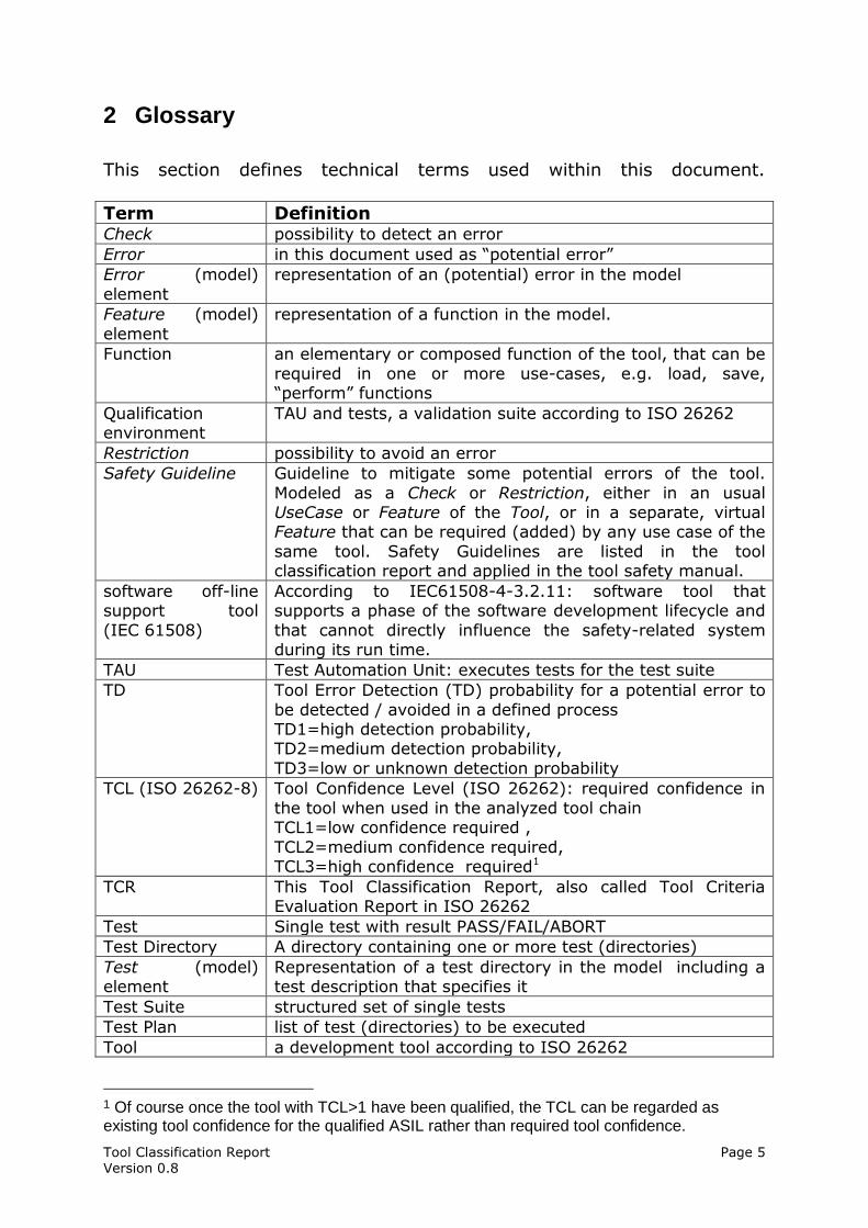
2 Glossary
This section defines technical terms used within this document.
Term Definition Check possibility to detect an error
Error in this document used as “potential error”
Error (model)
element
representation of an (potential) error in the model
Feature (model)
element
representation of a function in the model.
Function an elementary or composed function of the tool, that can be
required in one or more use-cases, e.g. load, save, “perform” functions
Qualification environment
TAU and tests, a validation suite according to ISO 26262
Restriction possibility to avoid an error
Safety Guideline Guideline to mitigate some potential errors of the tool.
Modeled as a Check or Restriction, either in an usual UseCase or Feature of the Tool, or in a separate, virtual Feature that can be required (added) by any use case of the
same tool. Safety Guidelines are listed in the tool classification report and applied in the tool safety manual.
software off-line support tool
(IEC 61508)
According to IEC61508-4-3.2.11: software tool that supports a phase of the software development lifecycle and
that cannot directly influence the safety-related system during its run time.
TAU Test Automation Unit: executes tests for the test suite
TD Tool Error Detection (TD) probability for a potential error to
be detected / avoided in a defined process TD1=high detection probability, TD2=medium detection probability,
TD3=low or unknown detection probability
TCL (ISO 26262-8) Tool Confidence Level (ISO 26262): required confidence in
the tool when used in the analyzed tool chain TCL1=low confidence required ,
TCL2=medium confidence required, TCL3=high confidence required1
TCR This Tool Classification Report, also called Tool Criteria Evaluation Report in ISO 26262
Test Single test with result PASS/FAIL/ABORT
Test Directory A directory containing one or more test (directories)
Test (model) element
Representation of a test directory in the model including a test description that specifies it
Test Suite structured set of single tests
Test Plan list of test (directories) to be executed
Tool a development tool according to ISO 26262
1 Of course once the tool with TCL>1 have been qualified, the TCL can be regarded as existing tool confidence for the qualified ASIL rather than required tool confidence.
Tool Classification Report Page 6 Version 0.8
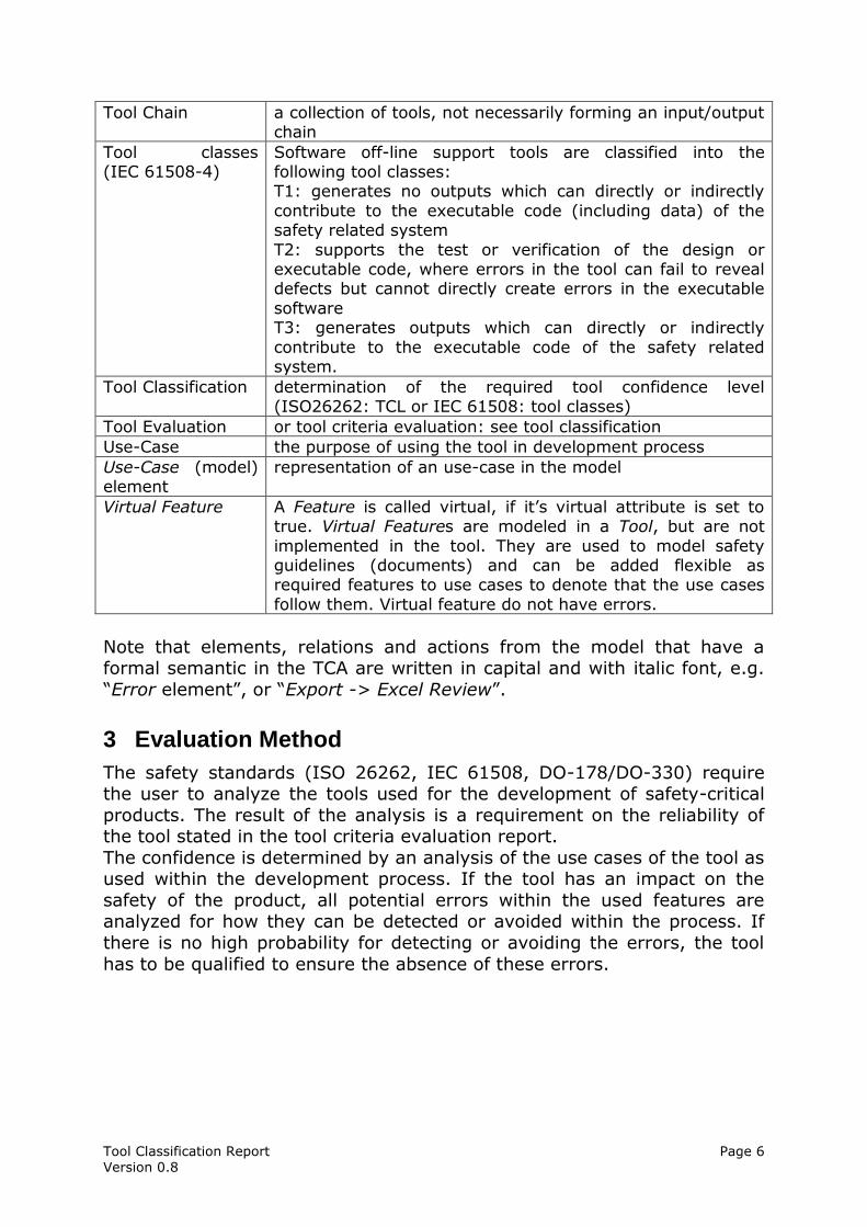
Tool Chain a collection of tools, not necessarily forming an input/output chain
Tool classes (IEC 61508-4)
Software off-line support tools are classified into the following tool classes: T1: generates no outputs which can directly or indirectly
contribute to the executable code (including data) of the safety related system
T2: supports the test or verification of the design or executable code, where errors in the tool can fail to reveal defects but cannot directly create errors in the executable
software T3: generates outputs which can directly or indirectly
contribute to the executable code of the safety related system.
Tool Classification determination of the required tool confidence level (ISO26262: TCL or IEC 61508: tool classes)
Tool Evaluation or tool criteria evaluation: see tool classification
Use-Case the purpose of using the tool in development process
Use-Case (model) element
representation of an use-case in the model
Virtual Feature A Feature is called virtual, if it’s virtual attribute is set to true. Virtual Features are modeled in a Tool, but are not
implemented in the tool. They are used to model safety guidelines (documents) and can be added flexible as required features to use cases to denote that the use cases
follow them. Virtual feature do not have errors.
Note that elements, relations and actions from the model that have a formal semantic in the TCA are written in capital and with italic font, e.g.
“Error element”, or “Export -> Excel Review”.
3 Evaluation Method
The safety standards (ISO 26262, IEC 61508, DO-178/DO-330) require the user to analyze the tools used for the development of safety-critical
products. The result of the analysis is a requirement on the reliability of the tool stated in the tool criteria evaluation report.
The confidence is determined by an analysis of the use cases of the tool as used within the development process. If the tool has an impact on the
safety of the product, all potential errors within the used features are analyzed for how they can be detected or avoided within the process. If
there is no high probability for detecting or avoiding the errors, the tool
has to be qualified to ensure the absence of these errors.
Tool Classification Report Page 7 Version 0.8
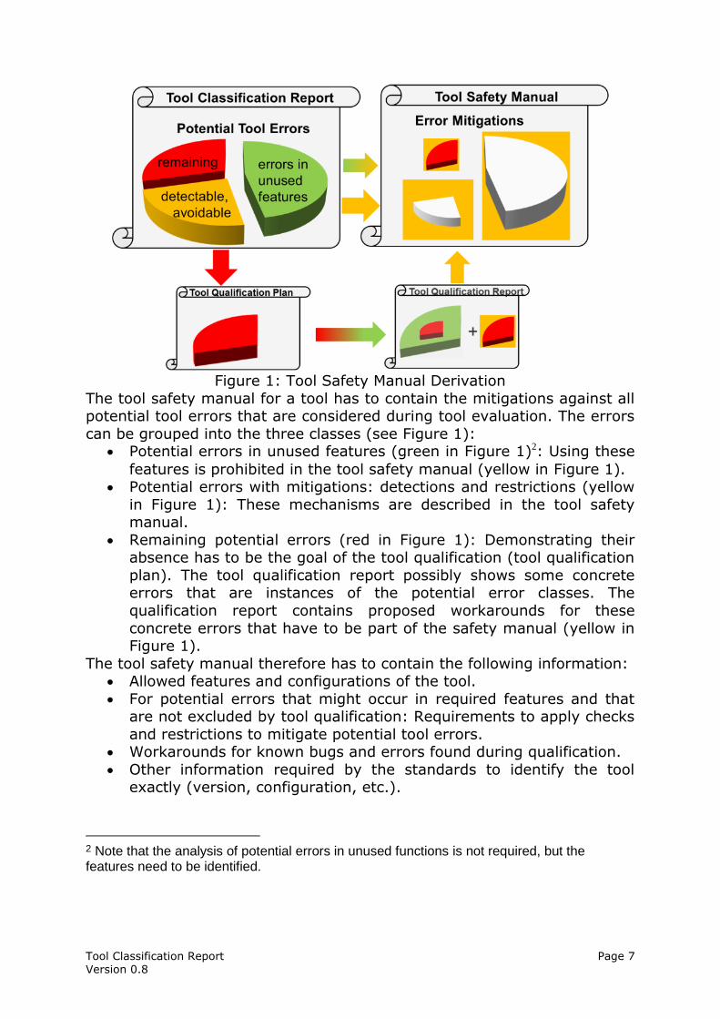
Figure 1: Tool Safety Manual Derivation
The tool safety manual for a tool has to contain the mitigations against all potential tool errors that are considered during tool evaluation. The errors
can be grouped into the three classes (see Figure 1): Potential errors in unused features (green in Figure 1)2: Using these
features is prohibited in the tool safety manual (yellow in Figure 1). Potential errors with mitigations: detections and restrictions (yellow
in Figure 1): These mechanisms are described in the tool safety manual.
Remaining potential errors (red in Figure 1): Demonstrating their absence has to be the goal of the tool qualification (tool qualification
plan). The tool qualification report possibly shows some concrete errors that are instances of the potential error classes. The
qualification report contains proposed workarounds for these
concrete errors that have to be part of the safety manual (yellow in Figure 1).
The tool safety manual therefore has to contain the following information: Allowed features and configurations of the tool.
For potential errors that might occur in required features and that are not excluded by tool qualification: Requirements to apply checks
and restrictions to mitigate potential tool errors. Workarounds for known bugs and errors found during qualification.
Other information required by the standards to identify the tool exactly (version, configuration, etc.).
2 Note that the analysis of potential errors in unused functions is not required, but the features need to be identified.
Tool Classification Report Page 8 Version 0.8
The tool qualification plan has to ensure that the identified potential errors
of the Testwell CTC++ Chain which are not detectable / avoidable cannot occur. This is done by applying a validation suite in a systematic way that
shows the absence of these potential errors.
If tools from the Testwell CTC++ Chain shall be qualified using validation we have to provide the following documents:
Test Plan: specifies the required test cases for execution Test Report: contains the test results
Test Automation Unit Manual: contains instructions to execute the planned tests cases correctly
Test suite validation and verification documents (plan and report): to ensure that the test suite shows the absence of the potential
errors if passed successfully The documents that depend on the model are typed using italic font.
In the case that the model and the validation suite needs to be extended and new test cases need to be produced and validated, the following
documents are required or need to be extended: Test specifications including a test strategy to show the absence of
the potential errors.
Test suite V&V plan & report The test suite needs validation against the implementation using a review
and a verification that they run correctly on the selected target. This quality process creates the confidence into the effectiveness of the test
suite. The V&V documents for the test suite are contained in the qualification kit to demonstrate the confidence to the user. If the test suite
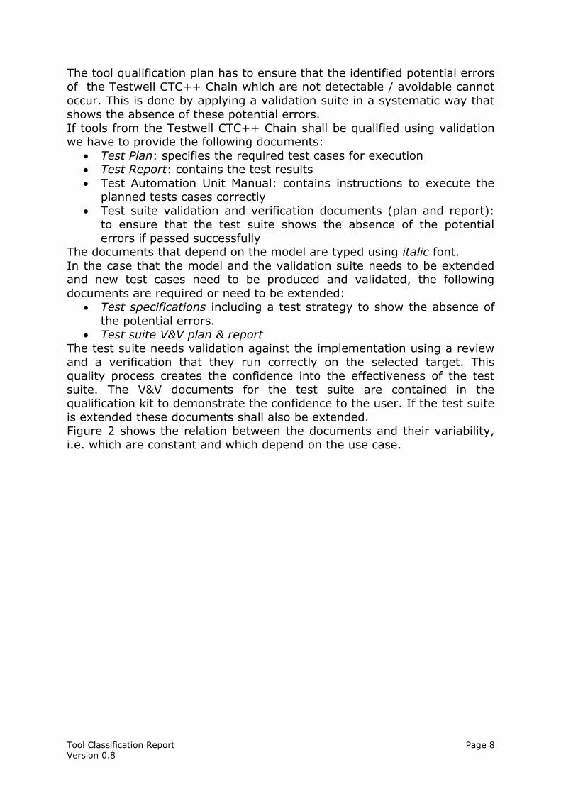
is extended these documents shall also be extended. Figure 2 shows the relation between the documents and their variability,
i.e. which are constant and which depend on the use case.
Tool Classification Report Page 9 Version 0.8
Figure 2: Documentation Plan
There are many documents in Figure 2 that are required and that need to
be adapted depending on the user’s process. The process is captured in
the qualification model by selecting the required tool features and the executed mitigations. The use case specific parts in the user specific
documents are generated from the qualification support tool.
The tools of the Testwell CTC++ Chain of <Customer> have been classified with the Validas Tool Chain Analyzer, which supports the
required classification using a tool chain model, and helped generating parts of this classification report.
In this section there are: a general description of the standard requirements, especially the
ISO 26262 requirements to the use of tools (see section 3.1), an abstract explanation of the methods used to analyze the model
using the process description (see section 3.2) and a tool supported approach using the “Tool Chain Analyzer” (see
section 3.3). The version 1.9.1 of the TCA has been used. More information and the tool
are on [TCA_UM] available. According to [ISO26262], this report is subject to the qualification
measures along with a Confirmation Review (see section 3.1.5).
3.1 Standard Requirements
The relevant safety standards have comparable approaches to tool
qualification. In all standards the goal is to ensure that the tools can not
Tool Classification Report Page 10 Version 0.8
impact the safety of the product, i.e. that all potential errors of the tool
are either absent or cannot impact the safety. And all standards do this by a combination of application and installation methods. The application
methods are safety guidelines that explain how to use the tool and
avoid/detect the potential errors, while the installation methods ensure that the installed tool works as expected, e.g. by testing it to show the
absence of the potential errors. All standards have a classification phase to determine the required
confidence into the tool and a qualification phase that provides this confidence or restricts the usage of the tools to confident scenarios.
However the classification and qualification methods differ in some details. Nevertheless our qualification approach is suitable for all standards and
does not require unnecessary work.
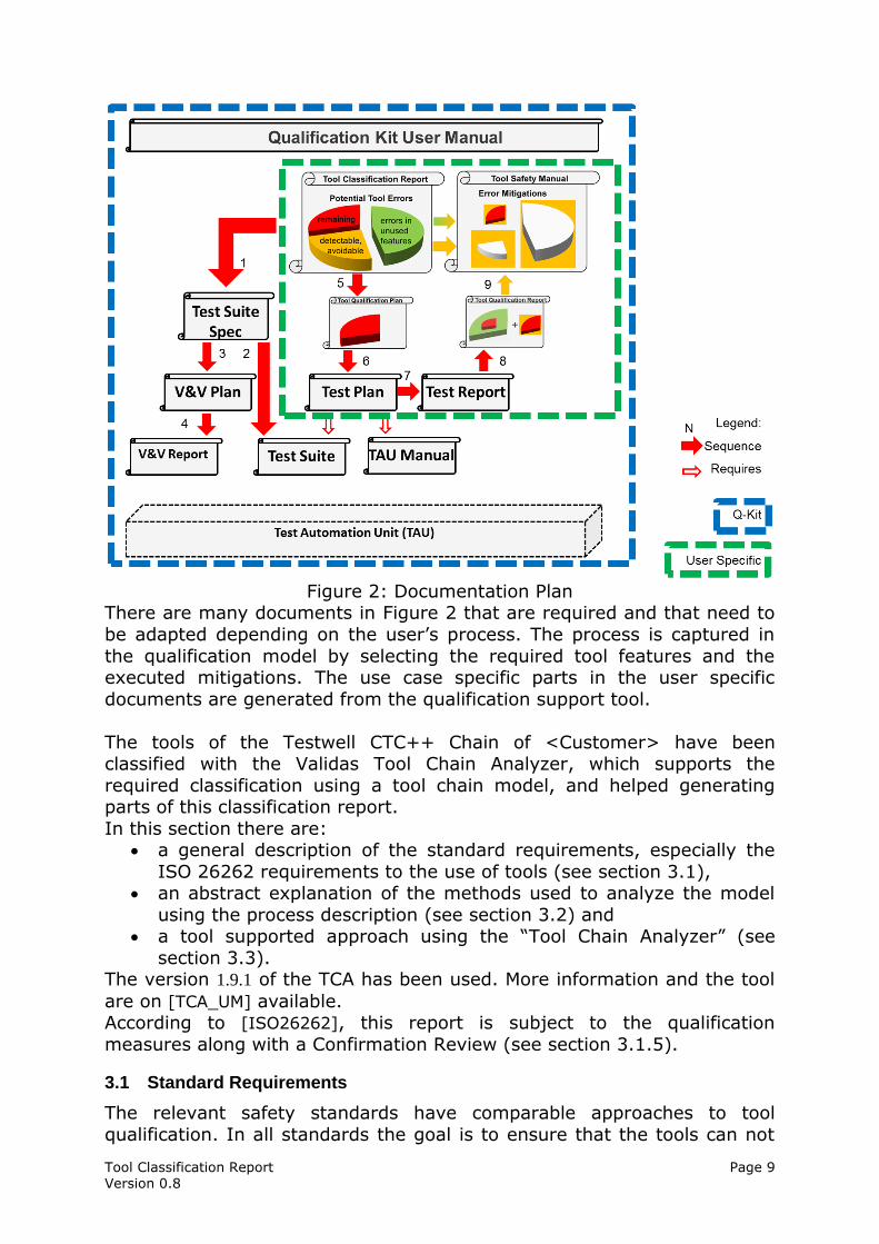
Figure 3: Comparison of Qualification Approaches
Figure 3 gives an overview on the different approaches. The main difference between ISO 26262 and the other standards is that the
classification of tools depends on the analysis of the potential errors and their detection, which increases the variability of the classification. The
impact and the supported methods/processes are considered in all standards as part of the classification. While the ISO does not differentiate
between kinds of the tools the other standards do and classify the tools for constructive methods (e.g. code generators and compilers) as more
critical than the other tools verification, automation and analytic tools. The results of the classification is the confidence needs (represented in pink
color in Figure 3). The DO expresses the tool confidence requirement by
criteria 1-3 the ISO 26262 as tool confidence levels and IEC 61508 and EN
Tool Classification Report Page 11 Version 0.8
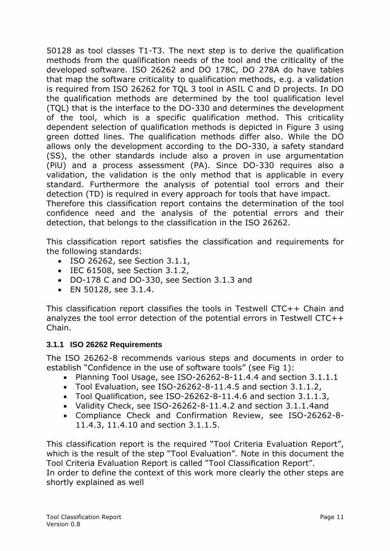
50128 as tool classes T1-T3. The next step is to derive the qualification
methods from the qualification needs of the tool and the criticality of the developed software. ISO 26262 and DO 178C, DO 278A do have tables
that map the software criticality to qualification methods, e.g. a validation
is required from ISO 26262 for TQL 3 tool in ASIL C and D projects. In DO the qualification methods are determined by the tool qualification level
(TQL) that is the interface to the DO-330 and determines the development of the tool, which is a specific qualification method. This criticality
dependent selection of qualification methods is depicted in Figure 3 using green dotted lines. The qualification methods differ also. While the DO
allows only the development according to the DO-330, a safety standard (SS), the other standards include also a proven in use argumentation
(PiU) and a process assessment (PA). Since DO-330 requires also a validation, the validation is the only method that is applicable in every
standard. Furthermore the analysis of potential tool errors and their detection (TD) is required in every approach for tools that have impact.
Therefore this classification report contains the determination of the tool confidence need and the analysis of the potential errors and their
detection, that belongs to the classification in the ISO 26262.
This classification report satisfies the classification and requirements for
the following standards: ISO 26262, see Section 3.1.1,
IEC 61508, see Section 3.1.2, DO-178 C and DO-330, see Section 3.1.3 and
EN 50128, see 3.1.4.
This classification report classifies the tools in Testwell CTC++ Chain and analyzes the tool error detection of the potential errors in Testwell CTC++
Chain.
3.1.1 ISO 26262 Requirements
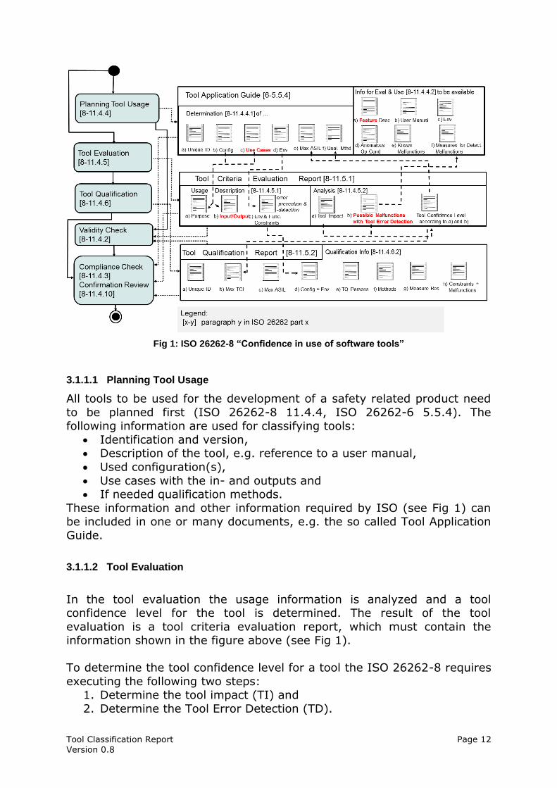
The ISO 26262-8 recommends various steps and documents in order to
establish “Confidence in the use of software tools” (see Fig 1): Planning Tool Usage, see ISO-26262-8-11.4.4 and section 3.1.1.1
Tool Evaluation, see ISO-26262-8-11.4.5 and section 3.1.1.2,
Tool Qualification, see ISO-26262-8-11.4.6 and section 3.1.1.3, Validity Check, see ISO-26262-8-11.4.2 and section 3.1.1.4and
Compliance Check and Confirmation Review, see ISO-26262-8-11.4.3, 11.4.10 and section 3.1.1.5.
This classification report is the required “Tool Criteria Evaluation Report”,
which is the result of the step “Tool Evaluation”. Note in this document the Tool Criteria Evaluation Report is called “Tool Classification Report”.
In order to define the context of this work more clearly the other steps are shortly explained as well
Tool Classification Report Page 12 Version 0.8
Fig 1: ISO 26262-8 “Confidence in use of software tools”
3.1.1.1 Planning Tool Usage
All tools to be used for the development of a safety related product need
to be planned first (ISO 26262-8 11.4.4, ISO 26262-6 5.5.4). The following information are used for classifying tools:
Identification and version, Description of the tool, e.g. reference to a user manual,
Used configuration(s),
Use cases with the in- and outputs and If needed qualification methods.
These information and other information required by ISO (see Fig 1) can be included in one or many documents, e.g. the so called Tool Application
Guide.
3.1.1.2 Tool Evaluation
In the tool evaluation the usage information is analyzed and a tool confidence level for the tool is determined. The result of the tool
evaluation is a tool criteria evaluation report, which must contain the information shown in the figure above (see Fig 1).
To determine the tool confidence level for a tool the ISO 26262-8 requires
executing the following two steps: 1. Determine the tool impact (TI) and
2. Determine the Tool Error Detection (TD).
Tool Classification Report Page 13 Version 0.8
The TCL is determined from these both values.
According to ISO 26262-8 11.4.5.2, the Tool Impact means: “the
possibility that a malfunction of a particular software tool can introduce or
fail to detect errors in a safety-related item or element being developed.
- TI1 shall be selected when there is an argument that there is no such possibility;
- TI2 shall be selected in all other cases”.
Tools with TI1 have a low confidence need, e.g. TCL1, and do not need to be qualified.
For all tools with possible impact (TI2) all use cases have to be analyzed
with the help of the potential errors and their detectability (TD: “Tool Error Detection”). All the use cases of the tool and their potential errors must be
considered and if possible measures that can detect or prevent these errors need to be assigned. For each measure a qualitative tool error
detection (TD) probability has to be assigned:
TD=1 if the probability to detect or prevent the error is HIGH, TD=2 if the probability to detect or prevent the error is MEDIUM and
TD=3 in all other cases (LOW or unknown probability). If several detection or prevention possibilities are available for one error
the one with the best detection/prevention probability can be used. In case of multiple potential errors for one tool or use case the one with the
worst detection or prevention probability determines the TD for the tool or use case.
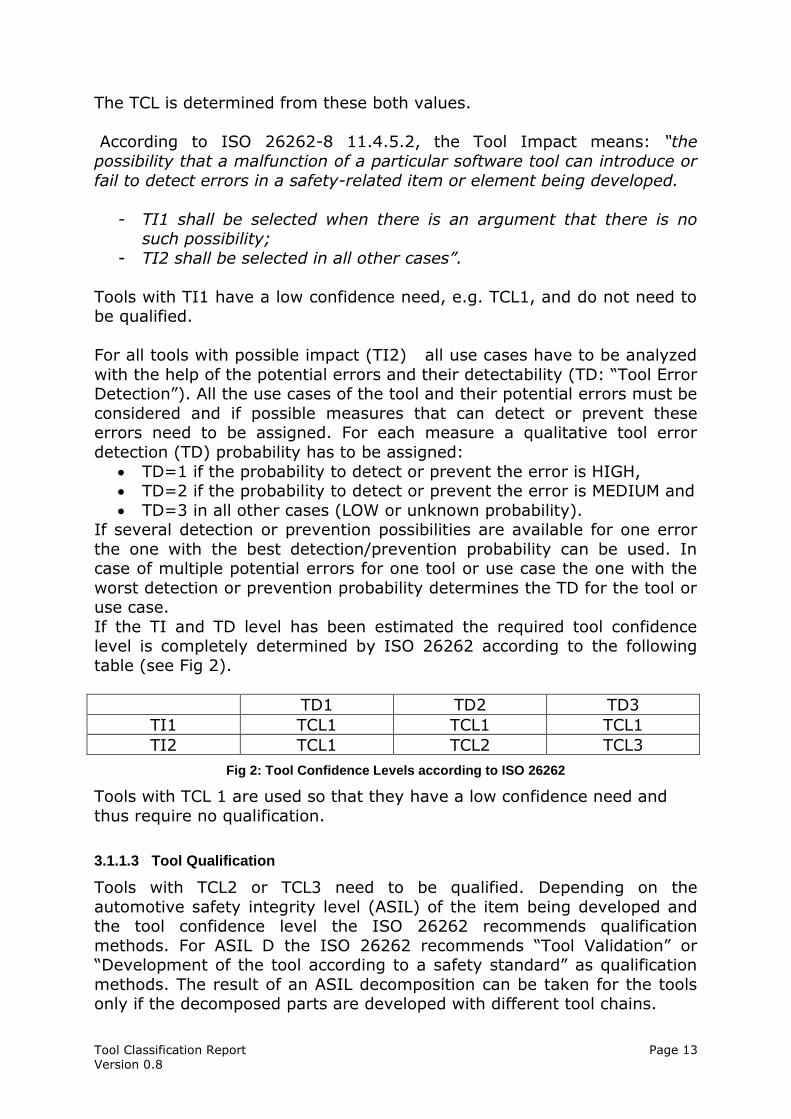
If the TI and TD level has been estimated the required tool confidence level is completely determined by ISO 26262 according to the following
table (see Fig 2).
TD1 TD2 TD3
TI1 TCL1 TCL1 TCL1
TI2 TCL1 TCL2 TCL3
Fig 2: Tool Confidence Levels according to ISO 26262
Tools with TCL 1 are used so that they have a low confidence need and
thus require no qualification.
3.1.1.3 Tool Qualification
Tools with TCL2 or TCL3 need to be qualified. Depending on the
automotive safety integrity level (ASIL) of the item being developed and the tool confidence level the ISO 26262 recommends qualification
methods. For ASIL D the ISO 26262 recommends “Tool Validation” or “Development of the tool according to a safety standard” as qualification
methods. The result of an ASIL decomposition can be taken for the tools only if the decomposed parts are developed with different tool chains.
Tool Classification Report Page 14 Version 0.8
The goal of tool qualification is to show the absence of the potential errors
identified during the tool evaluation. The result of tool qualification is a tool qualification report, which must contain the information shown in the
figure above (see Fig 1).
3.1.1.4 Validity Check
Classifications of tools and qualification of tools from other projects can be
reused. In both cases, the validity of the assumptions about the use cases
and potential errors needs to be checked for the current project (see [ISO26262] 8-11.4.2).
3.1.1.5 Compliance Check and Confirmation Review
For each used tool must be guaranteed that it fits to the configuration and
the version which was used for the classification. Particularly no functions and variants which were not classified may be applied. The measures
considered against potential errors in the classification must be executed in concrete development process (see [ISO26262] 8-11.4.10).
From ASIL B there must be a “Confirmation Review” that confirms, that The TCL was determined correctly and
The required qualification measures for the tool fit to the required confidence, i.e. demonstrate the absence of the critical, potential
errors.
3.1.2 IEC 61508
The IEC 61508, see [IEC61508] has a tool classification that does not depend on the use cases of the tools and the potential errors and the
measures to detect them.
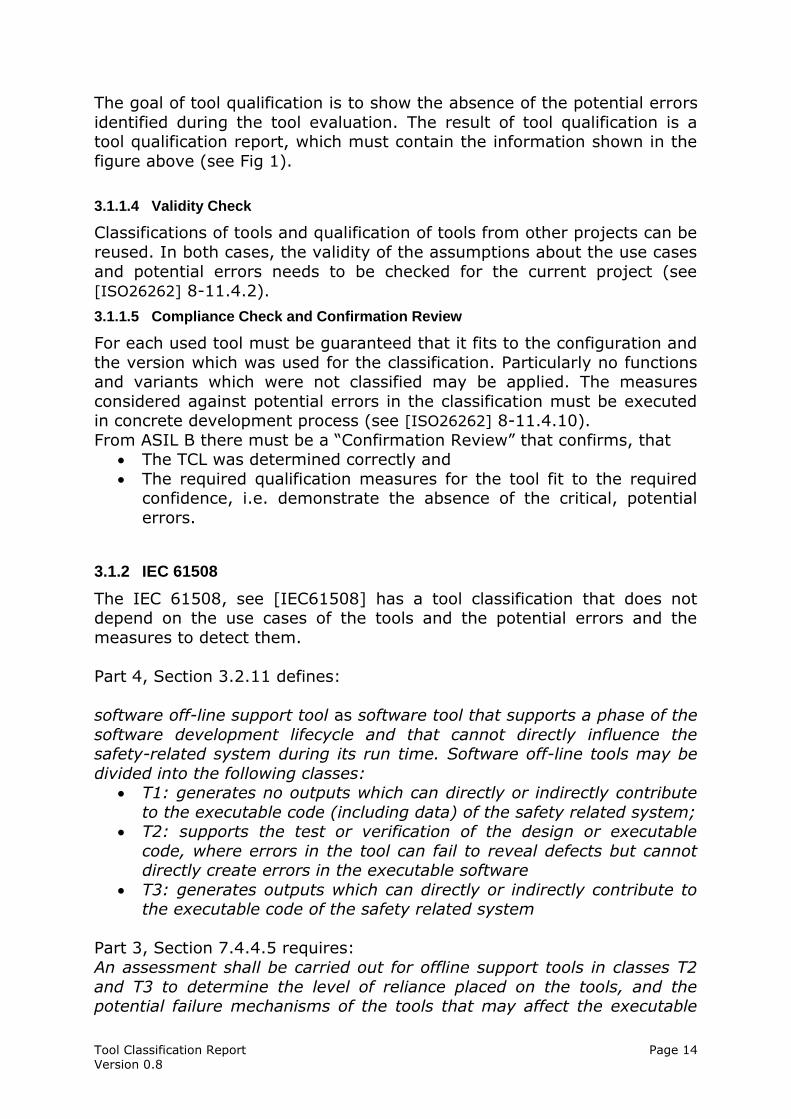
Part 4, Section 3.2.11 defines:
software off-line support tool as software tool that supports a phase of the
software development lifecycle and that cannot directly influence the safety-related system during its run time. Software off-line tools may be
divided into the following classes: T1: generates no outputs which can directly or indirectly contribute
to the executable code (including data) of the safety related system; T2: supports the test or verification of the design or executable
code, where errors in the tool can fail to reveal defects but cannot directly create errors in the executable software
T3: generates outputs which can directly or indirectly contribute to the executable code of the safety related system
Part 3, Section 7.4.4.5 requires:
An assessment shall be carried out for offline support tools in classes T2
and T3 to determine the level of reliance placed on the tools, and the potential failure mechanisms of the tools that may affect the executable
Tool Classification Report Page 15 Version 0.8
software. Where such failure mechanisms are identified, appropriate
mitigation measures shall be taken.
This is satisfied by the analysis the ISO 26262 requires for all relevant
tools and that is documented in this classification report.
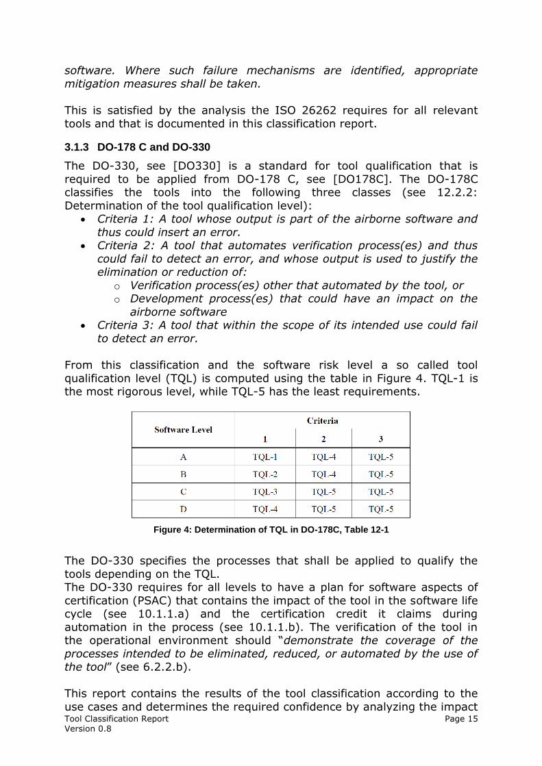
3.1.3 DO-178 C and DO-330
The DO-330, see [DO330] is a standard for tool qualification that is
required to be applied from DO-178 C, see [DO178C]. The DO-178C classifies the tools into the following three classes (see 12.2.2:
Determination of the tool qualification level): Criteria 1: A tool whose output is part of the airborne software and
thus could insert an error. Criteria 2: A tool that automates verification process(es) and thus
could fail to detect an error, and whose output is used to justify the elimination or reduction of:
o Verification process(es) other that automated by the tool, or o Development process(es) that could have an impact on the
airborne software Criteria 3: A tool that within the scope of its intended use could fail
to detect an error.
From this classification and the software risk level a so called tool
qualification level (TQL) is computed using the table in Figure 4. TQL-1 is the most rigorous level, while TQL-5 has the least requirements.
Figure 4: Determination of TQL in DO-178C, Table 12-1
The DO-330 specifies the processes that shall be applied to qualify the
tools depending on the TQL. The DO-330 requires for all levels to have a plan for software aspects of
certification (PSAC) that contains the impact of the tool in the software life cycle (see 10.1.1.a) and the certification credit it claims during
automation in the process (see 10.1.1.b). The verification of the tool in the operational environment should “demonstrate the coverage of the
processes intended to be eliminated, reduced, or automated by the use of the tool” (see 6.2.2.b).
This report contains the results of the tool classification according to the
use cases and determines the required confidence by analyzing the impact
Tool Classification Report Page 16 Version 0.8
of the potential errors. Hence it satisfies the above requirements from the
DO-330 / DO 178 C.
Furthermore the TQL can be reduced based on this tool classification
report if the potential tool errors have high detection probabilities, since the DO-330 contains the following statement (FAQ D.2): To reduce a
tool’s qualification level, the reduction needs to be justified by performing a tool use and impact analysis. This analysis needs to evaluate the overall
use of the tool in the development process and its impact on the software being produced.
Therefore this classification report is an essential contribution to all qualification levels from DO-178 C and DO-330 and in addition can be
used to reduce the tool qualification level.
3.1.4 EN 50128
Similar to IEC 61508 (see Section 3.1.2) the EN 50128, see [EN50128]
defines in Sections 3.1.42, 3.1.43, 3.1.44 the following tool classes: tool class T1
generates no outputs which can directly or indirectly contribute to the executable code (including data) of the software
tool class T2
supports the test or verification of the design or executable code, where errors in the tool can fail to reveal defects but cannot directly
create errors in the executable software tool class T3
generates outputs which can directly or indirectly contribute to the executable code (including data) of the safety related system
In Section 6.7 on the supporting process the classification is required in
6.7.1.1: The objective is to provide evidence that potential failures of tools do not
adversely affect the integrated toolset output in a safety related manner that is undetected by technical and/or organizational measures outside
the tool. To this end, software tools are categorised into three classes namely, T1, T2 & T3 respectively.
The analysis of the potential failure is required in Section 6.7.4.2: The selection of the tools in classes T2 and T3 shall be justified. The
justification shall include the identification of potential failures which can be injected into the tools output and the measures to avoid or handle such
failures.
This justification for T2 and T3 tools is satisfied by the analysis the ISO 26262 requires for all relevant tools and that is documented in this
classification report in the generated section 6. A detailed tracing of the EN 50128 requirements is in the tool qualification plan [TQP] and report.
Tool Classification Report Page 17 Version 0.8
3.2 Tool Chain Analysis Method
This section describes the Tool Chain Analysis method (TCA) for the “tool
evaluation” that has been applied in order to fulfill the classification requirements of ISO in the previous section 3.1.1. This method
determines TI, tool error detection TD and TCL for an entire tool chain in
the following steps:
1. Define list of tools 2. Gather tool application facts and identify use cases
3. Determine tool impact (TI) 4. Identify potential errors
5. Identify and assign checks and restrictions (TD) 6. Compute Tool Confidence Level (TCL)
7. Document evaluation results
In the following subsections these steps are explained in detail.
Note: Even if all those tasks depend on the process of the user, qualification kits can provide models with the required potential errors in
their features, allowing to compose user specific applications (see Section
3.4). Those models can be extended to other tools using the TCA tool (Section )
3.2.1 Define List of Tools
The first step for a tool evaluation is to write a list of all tools that are used in safety related development parts of the product. For each tool an
expert should be determined in order to be able to get the required details on the use cases.
3.2.2 Gather tool application facts and identify use cases
For each tool the following facts need to be collected and documented: Tool versions,
Configuration (it could depend of the installation, Used features,
If mentioned in the tool description: o potential errors of the tool/features,
o Measures for prevention and detection of these and other possible errors.
A use case contains at least the following information: Title: needed to identify the use case.
Description, If necessary the used tool features,
Inputs and Outputs.
Tool Classification Report Page 18 Version 0.8
The individual tools are integrated over the input and output artifacts to a
tool chain. It is important to give the artifacts consistent names in order to avoid confusion and duplication.
A convenient representation of the input/output relationships of use cases
in a tool chain is the so called tool artifact matrix. It represents all artifacts in lines and all the use cases of the tool in columns. The entries in
the matrix indicate what actions the use cases executed on the artifacts (Read/Write).
3.2.3 Determine Tool Impact
The “Tool Impact” describes the possibility that a tool compromises the safety of a developed product (see ISO 26262-8 11.4.5.2 and section
3.1.2). Two questions need to be answered to determine the tool impact: 1) Can the tool insert an error in the product?
2) Can the tool overlook an error that could affect the product? If both questions can be answered with No, the tool has no impact on the
product safety (TI1). Otherwise there is the possibility of impact (TI2) These two questions need to be answered for every use case of the tool,
the data flow of the use cases from the tool artifact matrix can be used for that.
3.2.4 Identify Potential Errors
For each use case of a tool the potential errors need to be identified.
The identification of potential errors is a very crucial part of the tool evaluation, because an oversight of potential errors can lead to an
incorrect classification. A good error analysis should achieve the following goals:
1) Completeness: All potential errors are considered. 2) Uniformness: All use cases are analyzed with the same method and
same intensity. 3) Appropriate Abstraction: The level of abstraction for error
descriptions has to be appropriate. If error descriptions are too abstract, assigning suitable checks becomes very difficult. If error
descriptions are too concrete, some errors might not be covered.
In order to achieve these goals two strategies are used to analyze each use case of a tool (see [SAFECOMP12]):
1. An artifact oriented Black Box approach (see section 3.2.4.1)
2. A functional White Box approach (see section 3.2.4.2).
The errors found thereby should be consolidated for the specific places of occurrence. This is described in section 3.2.4.3.
3.2.4.1 Black Box Error Identification Strategy:
The black box strategy considers the tools as a black box and identifies the potential errors only on the basis of the artifacts that are created by
the tool, because these contain the errors.
Tool Classification Report Page 19 Version 0.8
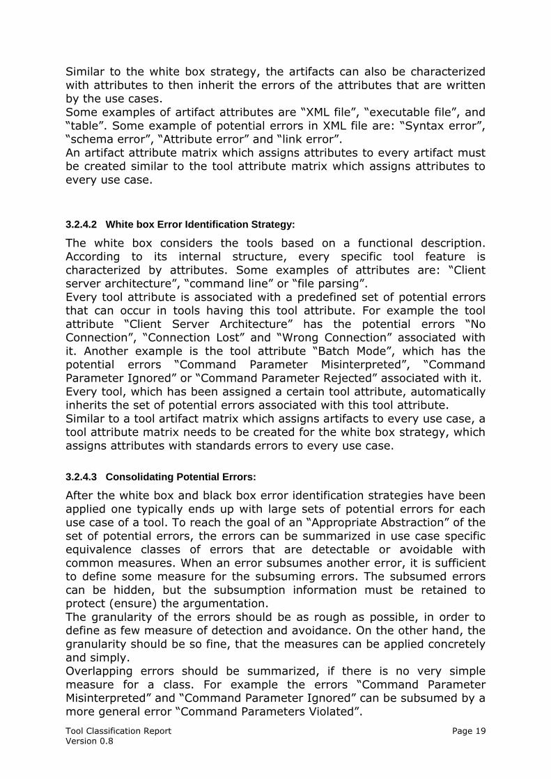
Similar to the white box strategy, the artifacts can also be characterized
with attributes to then inherit the errors of the attributes that are written by the use cases.
Some examples of artifact attributes are “XML file”, “executable file”, and
“table”. Some example of potential errors in XML file are: “Syntax error”, “schema error”, “Attribute error” and “link error”.
An artifact attribute matrix which assigns attributes to every artifact must be created similar to the tool attribute matrix which assigns attributes to
every use case.
3.2.4.2 White box Error Identification Strategy:
The white box considers the tools based on a functional description. According to its internal structure, every specific tool feature is
characterized by attributes. Some examples of attributes are: “Client server architecture”, “command line” or “file parsing”.
Every tool attribute is associated with a predefined set of potential errors that can occur in tools having this tool attribute. For example the tool
attribute “Client Server Architecture” has the potential errors “No Connection”, “Connection Lost” and “Wrong Connection” associated with
it. Another example is the tool attribute “Batch Mode”, which has the potential errors “Command Parameter Misinterpreted”, “Command
Parameter Ignored” or “Command Parameter Rejected” associated with it.
Every tool, which has been assigned a certain tool attribute, automatically inherits the set of potential errors associated with this tool attribute.
Similar to a tool artifact matrix which assigns artifacts to every use case, a tool attribute matrix needs to be created for the white box strategy, which
assigns attributes with standards errors to every use case.
3.2.4.3 Consolidating Potential Errors:
After the white box and black box error identification strategies have been
applied one typically ends up with large sets of potential errors for each use case of a tool. To reach the goal of an “Appropriate Abstraction” of the
set of potential errors, the errors can be summarized in use case specific equivalence classes of errors that are detectable or avoidable with
common measures. When an error subsumes another error, it is sufficient to define some measure for the subsuming errors. The subsumed errors
can be hidden, but the subsumption information must be retained to protect (ensure) the argumentation.
The granularity of the errors should be as rough as possible, in order to define as few measure of detection and avoidance. On the other hand, the
granularity should be so fine, that the measures can be applied concretely
and simply. Overlapping errors should be summarized, if there is no very simple
measure for a class. For example the errors “Command Parameter Misinterpreted” and “Command Parameter Ignored” can be subsumed by a
more general error “Command Parameters Violated”.
Tool Classification Report Page 20 Version 0.8
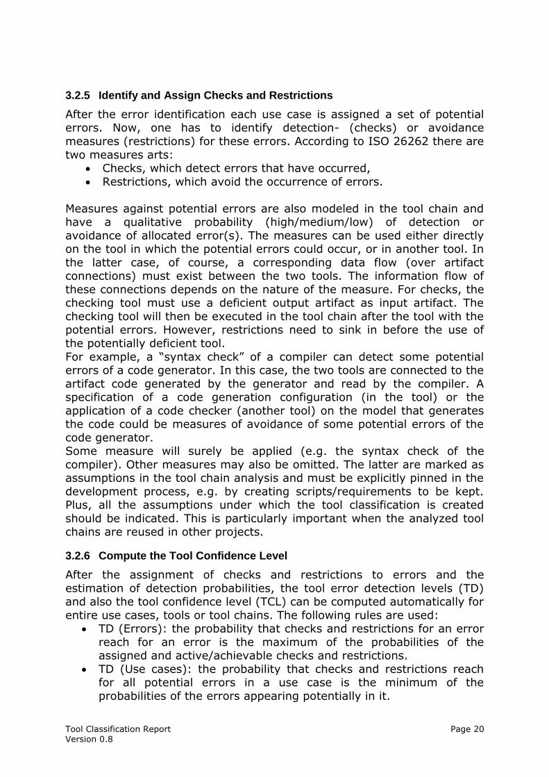
3.2.5 Identify and Assign Checks and Restrictions
After the error identification each use case is assigned a set of potential errors. Now, one has to identify detection- (checks) or avoidance
measures (restrictions) for these errors. According to ISO 26262 there are
two measures arts: Checks, which detect errors that have occurred,
Restrictions, which avoid the occurrence of errors.
Measures against potential errors are also modeled in the tool chain and have a qualitative probability (high/medium/low) of detection or
avoidance of allocated error(s). The measures can be used either directly on the tool in which the potential errors could occur, or in another tool. In
the latter case, of course, a corresponding data flow (over artifact connections) must exist between the two tools. The information flow of
these connections depends on the nature of the measure. For checks, the checking tool must use a deficient output artifact as input artifact. The
checking tool will then be executed in the tool chain after the tool with the potential errors. However, restrictions need to sink in before the use of
the potentially deficient tool.
For example, a “syntax check” of a compiler can detect some potential errors of a code generator. In this case, the two tools are connected to the
artifact code generated by the generator and read by the compiler. A specification of a code generation configuration (in the tool) or the
application of a code checker (another tool) on the model that generates the code could be measures of avoidance of some potential errors of the
code generator. Some measure will surely be applied (e.g. the syntax check of the
compiler). Other measures may also be omitted. The latter are marked as assumptions in the tool chain analysis and must be explicitly pinned in the
development process, e.g. by creating scripts/requirements to be kept. Plus, all the assumptions under which the tool classification is created
should be indicated. This is particularly important when the analyzed tool chains are reused in other projects.
3.2.6 Compute the Tool Confidence Level
After the assignment of checks and restrictions to errors and the
estimation of detection probabilities, the tool error detection levels (TD) and also the tool confidence level (TCL) can be computed automatically for
entire use cases, tools or tool chains. The following rules are used: TD (Errors): the probability that checks and restrictions for an error
reach for an error is the maximum of the probabilities of the assigned and active/achievable checks and restrictions.
TD (Use cases): the probability that checks and restrictions reach for all potential errors in a use case is the minimum of the
probabilities of the errors appearing potentially in it.
Tool Classification Report Page 21 Version 0.8
TD (Tool): the probability that checks and restrictions reach for all
potential errors in a tool is the minimum of the probabilities of all the use cases in the tool.
The tool Confidence Level results from the so determined probabilities
according to ISO 26262 (see Fig 2) as follows: TD=High => TCL 1
TD=MEDIUM => TCL 2 TD=LOW => TCL3
The TCL can be computed in two ways:
1) With the use of assumptions, 2) Without the use of assumptions.
In both calculations only the used use cases are committed. Particularly if reusable functions models of tools are available (when indicated with high
TCL), only the functions that are used in the use cases are considered.
3.2.7 Document the evaluation results
The evaluation results for each tool and the entire tool chain need to be
documented in the tool criteria evaluation report, in particular the TCL and the thoughts it results from. It begins with the Tool Impact documentation
(TI) and contains all the needed information for computing the TCL. The
analysis must be confirmed in a “Confirmation Review” that must confirm the argumentation.
3.2.7.1 TI Determination
For the determination of the tool impact two questions need to be answered:
“Can an error occur in the product?” and “Can an error be ignored in the product?”.
If one of the questions is answered with Yes, then there is a possible impact. The question must be answered on the basis of the data flow of
the use cases and tools. If no impact can be shown the decision must be supported with an informal argument. For example, typical justifications
for the editor are that the inputs are controlled visually (WYSIWYG) and the errors would be noticed. The decisions must be documented, this
occurs in chapter 5.
3.2.7.2 TCL Determination
The documentation of the TCL computation must contain all the relevant
relations, in particular the potential errors and their checks and restrictions (incl. probabilities) for all uses cases.
All these information are in chapter 6 of this document. In this chapter there is an overview table listing the determined TCL for each tool. In
addition this chapter must also contain the argumentation for the TCL
determination. This is achieved by having a separate and modular section for each tool. Each tool section has the following structure:
Tool Classification Report Page 22 Version 0.8
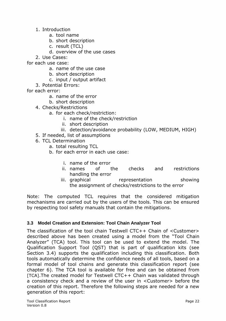
1. Introduction
a. tool name b. short description
c. result (TCL)
d. overview of the use cases 2. Use Cases:
for each use case: a. name of the use case
b. short description c. input / output artifact
3. Potential Errors: for each error:
a. name of the error b. short description
4. Checks/Restrictions a. for each check/restriction:
i. name of the check/restriction ii. short description
iii. detection/avoidance probability (LOW, MEDIUM, HIGH)
5. If needed, list of assumptions 6. TCL Determination
a. total resulting TCL b. for each error in each use case:
i. name of the error
ii. names of the checks and restrictions handling the error
iii. graphical representation showing the assignment of checks/restrictions to the error
Note: The computed TCL requires that the considered mitigation
mechanisms are carried out by the users of the tools. This can be ensured by respecting tool safety manuals that contain the mitigations.
3.3 Model Creation and Extension: Tool Chain Analyzer Tool
The classification of the tool chain Testwell CTC++ Chain of <Customer> described above has been created using a model from the “Tool Chain
Analyzer” (TCA) tool. This tool can be used to extend the model. The Qualification Support Tool (QST) that is part of qualification kits (see
Section 3.4) supports the qualification including this classification. Both tools automatically determine the confidence needs of all tools, based on a
formal model of tool chains and generate this classification report (see chapter 6). The TCA tool is available for free and can be obtained from
[TCA].The created model for Testwell CTC++ Chain was validated through a consistency check and a review of the user in <Customer> before the
creation of this report. Therefore the following steps are needed for a new generation of this report:
Tool Classification Report Page 23 Version 0.8
Model adaptation (see Section 3.3.1),
Consistency check of the model (see Section 3.3.2), Model review (see Section 3.3.3) and
Report generation (see Section 3.3.4).
The steps are described in the following sections. Details can be found in
[TCA_UM] and can be learned in a training course on the tool.
3.3.1 Modeling
The model of the tool chain Testwell CTC++ Chain consists of an element “ToolChain” that contains an element “Tool” for every tool of the tool
chain. It also contains the used artifacts that show the relation between the tools.
For each tool, the use cases are modeled, in which the tool is used in <Customer>. Potential errors, checks and restrictions are assigned with
their probabilities to each use case. The error elements are related to the checks and the restrictions that detect or avoid them. The TD and the TCL
are computed according to ISO 26262 (see section 3.1.1 and 3.2.6) with the probabilities of the assigned checks and restrictions. If several use
cases use the same functionalities in a tool, then it makes sense to model
these tool functionalities as features. Since each feature can be used by several use cases, it is possible to avoid redundant error definitions as the
errors are not individually defined for each use case, but they are assigned the features, in which they can occur. The errors of the features
can be reused. They are inferred to the use cases and represented as “Inferred Error” elements.
The tool chain model can be used in different variants or can be extended to new variants. The variants are managed in the element “ToolChain”.
The elements (tools, use cases, artifacts) that are not considered in all variants have a link to the variants in which they are considered.
The reviewed errors are important for the quality of the analysis. Therefore, the tools support a systematic process to identify potential
errors (black box and white box). These are assigned to the artifacts and the use cases through attributes. The attributes are listed in the ToolChain
model under “DefaultErrorAttributes”. Errors that derive from attributes
are called “Derived Errors” and can be disabled from the model, but before they must be listed in specific errors (list of “subsumed errors”) for the
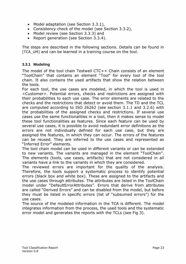
use cases. The source of the modeled information in the TCA is different. The model
integrates information from the process, the used tools and the systematic error model and generates the reports with the TCLs (see Fig 3).
Tool Classification Report Page 24 Version 0.8
Fig 3: Validas Tool Chain Analyzer and its environment
The model can be directly created in the tool. Some information can also be imported via an Excel interface (e.g. the Tool Artifact Matrix).
3.3.2 Validation
There are two steps for the model validation:
1. Consistence check of the model and 2. Textual and technical check (review).
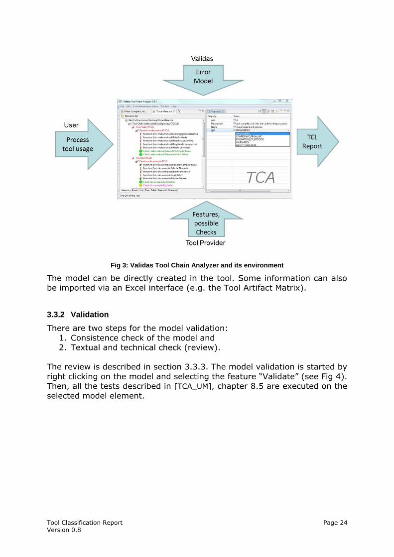
The review is described in section 3.3.3. The model validation is started by
right clicking on the model and selecting the feature “Validate” (see Fig 4). Then, all the tests described in [TCA_UM], chapter 8.5 are executed on the
selected model element.
Tool Classification Report Page 25 Version 0.8
Fig 4: validation start in TCA
No more errors should occur. The following tests could be exceptions (see
[TCA_UM] for detailed descriptions of the checks): Deactivated (checks deactivated elements): this condition may be
violated only by tools that are modelled in this chain, but can not be
used (for example to analyse a variant of a tool chain). UseCaseComplete (checks if the use case contains an error model):
this condition may be violated only by use cases, which are carried out by people (e.g. a review). . In this case the incompleteness
message which indicates missing errors is acceptable. In the present tool chain Testwell CTC++ Chain no other “syntactic
violations” exist.
3.3.3 Review
The review of the model ensures the textual and technical correctness of the model in the first instance. This is especially necessary if the modeler
and the assistants who carry out the test are different people, e.g. model creation by the Validas employees or central departments for specific
development projects. The review can be done in the model or in excel.
An excel table is generated, that generates the following columns for each
error, check and restriction in all use cases/tools: Name of the reviewer
Is the probability correctly selected/computed (OK/NOK)? Is the check/restriction performed (true/false)?
Comment, e.g. are there further elements? Or reasons for differences.
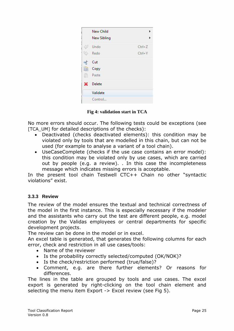
The lines in the table are grouped by tools and use cases. The excel export is generated by right-clicking on the tool chain element and
selecting the menu item Export -> Excel review (see Fig 5).
Tool Classification Report Page 26 Version 0.8
Fig 5: Export Review Table
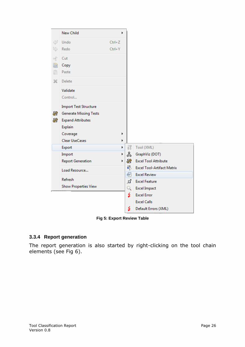
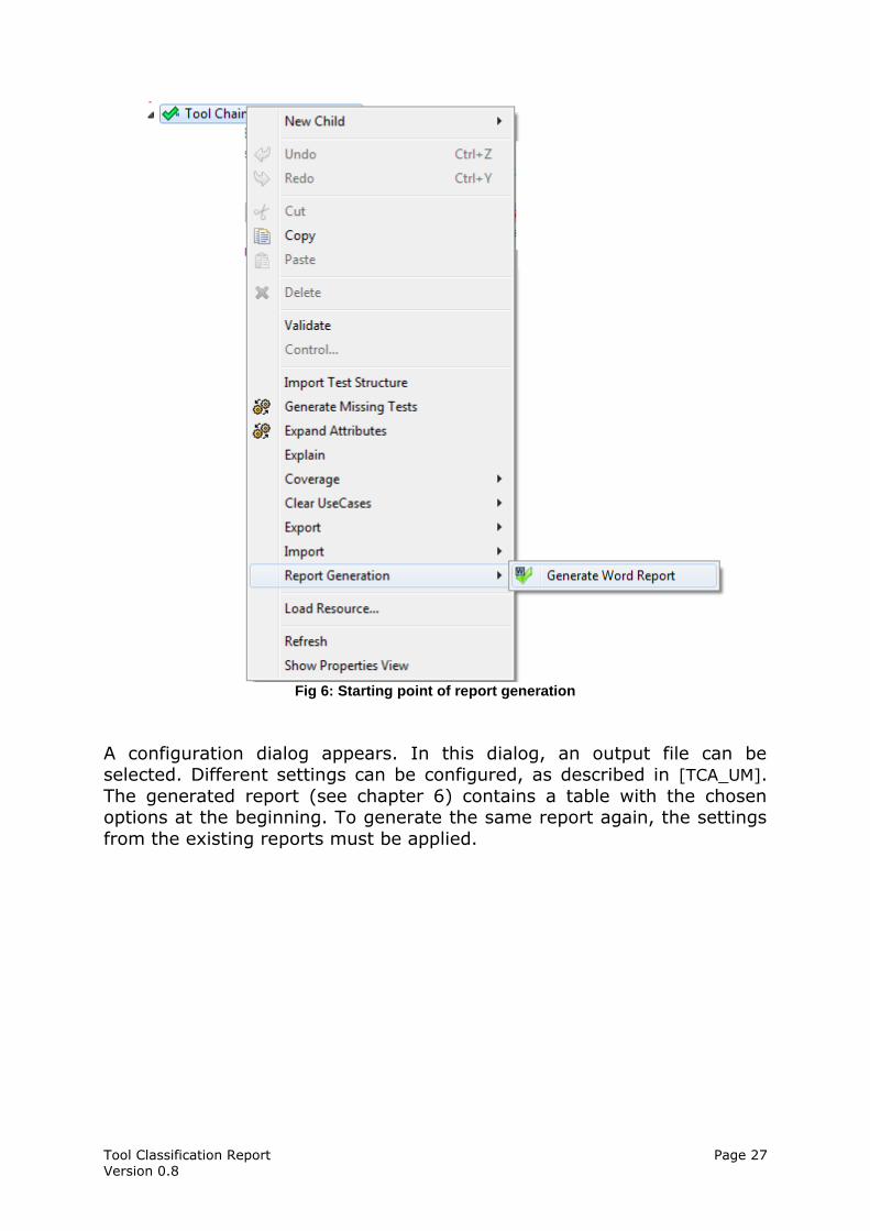
3.3.4 Report generation
The report generation is also started by right-clicking on the tool chain
elements (see Fig 6).
Tool Classification Report Page 27 Version 0.8
Fig 6: Starting point of report generation
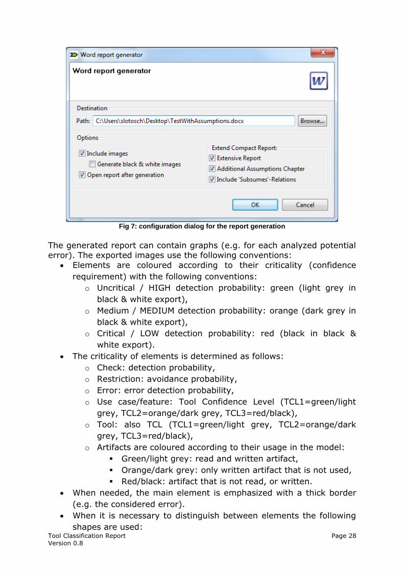
A configuration dialog appears. In this dialog, an output file can be selected. Different settings can be configured, as described in [TCA_UM].
The generated report (see chapter 6) contains a table with the chosen options at the beginning. To generate the same report again, the settings
from the existing reports must be applied.
Tool Classification Report Page 28 Version 0.8
Fig 7: configuration dialog for the report generation
The generated report can contain graphs (e.g. for each analyzed potential error). The exported images use the following conventions:
Elements are coloured according to their criticality (confidence
requirement) with the following conventions:
o Uncritical / HIGH detection probability: green (light grey in
black & white export),
o Medium / MEDIUM detection probability: orange (dark grey in
black & white export),
o Critical / LOW detection probability: red (black in black &
white export).
The criticality of elements is determined as follows:
o Check: detection probability,
o Restriction: avoidance probability,
o Error: error detection probability,
o Use case/feature: Tool Confidence Level (TCL1=green/light
grey, TCL2=orange/dark grey, TCL3=red/black),
o Tool: also TCL (TCL1=green/light grey, TCL2=orange/dark
grey, TCL3=red/black),
o Artifacts are coloured according to their usage in the model:
Green/light grey: read and written artifact,
Orange/dark grey: only written artifact that is not used,
Red/black: artifact that is not read, or written.
When needed, the main element is emphasized with a thick border
(e.g. the considered error).
When it is necessary to distinguish between elements the following
shapes are used:
Tool Classification Report Page 29 Version 0.8
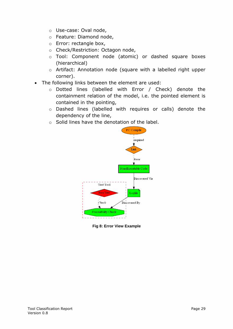
o Use-case: Oval node,
o Feature: Diamond node,
o Error: rectangle box,
o Check/Restriction: Octagon node,
o Tool: Component node (atomic) or dashed square boxes
(hierarchical)
o Artifact: Annotation node (square with a labelled right upper
corner).
The following links between the element are used:
o Dotted lines (labelled with Error / Check) denote the
containment relation of the model, i.e. the pointed element is
contained in the pointing,
o Dashed lines (labelled with requires or calls) denote the
dependency of the line,
o Solid lines have the denotation of the label.
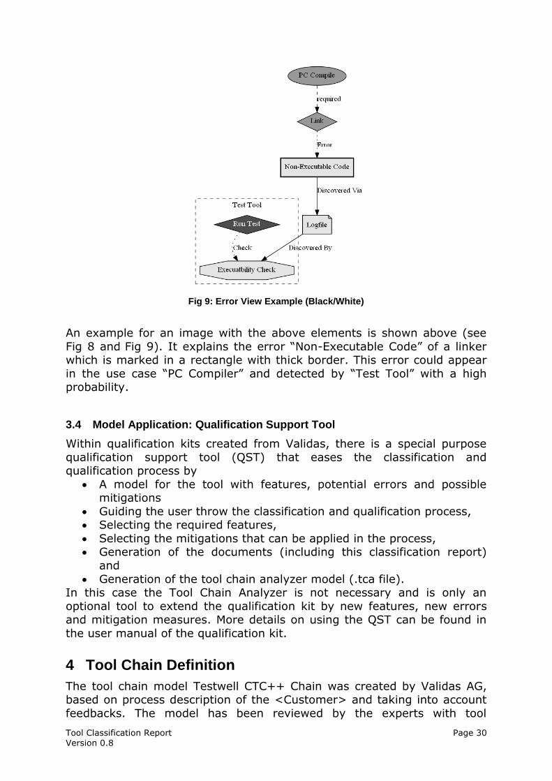
Fig 8: Error View Example
Tool Classification Report Page 30 Version 0.8
Fig 9: Error View Example (Black/White)
An example for an image with the above elements is shown above (see
Fig 8 and Fig 9). It explains the error “Non-Executable Code” of a linker which is marked in a rectangle with thick border. This error could appear
in the use case “PC Compiler” and detected by “Test Tool” with a high probability.
3.4 Model Application: Qualification Support Tool
Within qualification kits created from Validas, there is a special purpose
qualification support tool (QST) that eases the classification and qualification process by
A model for the tool with features, potential errors and possible mitigations
Guiding the user throw the classification and qualification process, Selecting the required features,
Selecting the mitigations that can be applied in the process, Generation of the documents (including this classification report)
and
Generation of the tool chain analyzer model (.tca file). In this case the Tool Chain Analyzer is not necessary and is only an
optional tool to extend the qualification kit by new features, new errors and mitigation measures. More details on using the QST can be found in
the user manual of the qualification kit.
4 Tool Chain Definition
The tool chain model Testwell CTC++ Chain was created by Validas AG, based on process description of the <Customer> and taking into account
feedbacks. The model has been reviewed by the experts with tool
Tool Classification Report Page 31 Version 0.8
responsibilities and thus it is a valid model of the current Testwell CTC++
Chain. The other projects that want to use the existing classification results have to ensure that:
a) the tool chain is used as described (data flow, counter-measures,…),
b) no new tools, features/use cases in particular are added. Under these circumstances, the model is valid, and the tool confidence
level that has been calculated is actually the level of the used tool chain and the used tools. The conformity of the model and of this report must
be checked for each other development projects (as imposed by the ISO “Confirmation Review” of the TCL und the required qualification measures,
see [ISO26262], 8- 11.4.10).
In addition to the generated classification of the tools in this report, the following information about all used tools have to be determined (e.g. in
the Safety Manual of the tool chain or individual tools): version of the tool (is important in particular for qualified tools, since
each tool-related change needs to be re-qualified), tool configuration(s),
tool environment,
maximum risk level (ASIL,SIL or Risk Class) of the tool or any existing qualifications,
description of the features/user manual, known errors and measures.
Particularly the last point is important for a tool management, because the users must be informed about tools mistakes of qualified tools.
5 Tool Impact Determination
The Tool Impact (TI) of the tool chain Testwell CTC++ Chain was determined as described in section 3.2.3 and 3.2.7.1. The Tool Impact is
specified with the calculation of the TCL in section 6 under the result overview and for every tools and every Use-Case separately.
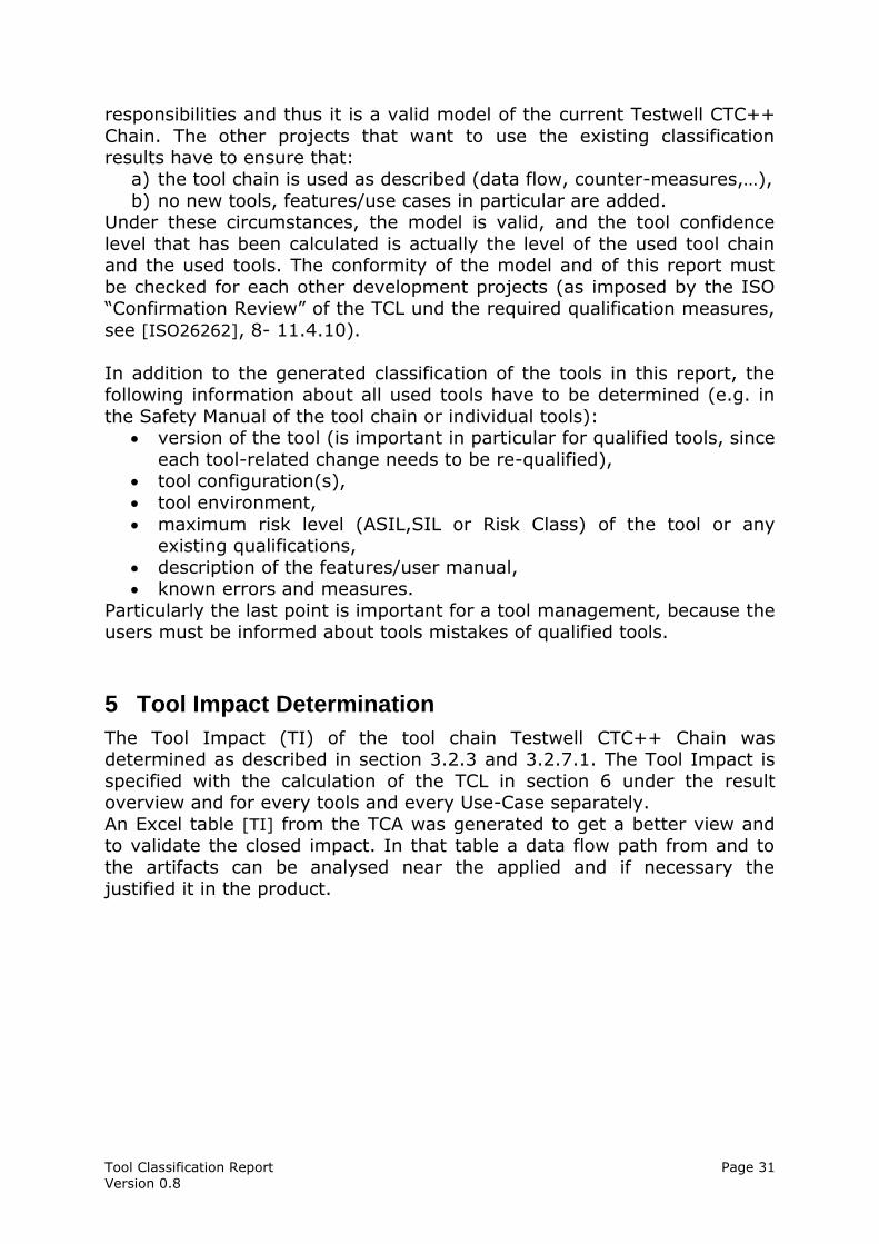
An Excel table [TI] from the TCA was generated to get a better view and to validate the closed impact. In that table a data flow path from and to
the artifacts can be analysed near the applied and if necessary the justified it in the product.
Tool Classification Report Page 32 Version 0.8
Fig 12: TI determination in Excel
Fig 12 shows an exemplary determination of the tool impact in one of the exported (and importable) Excel table. The tool impact for the tool chain
Testwell CTC++ Chain is in [TI] or in section 6.
Tool Classification Report Page 33 Version 0.8
6 [generated]
Tool Classification Report Page 34 Version 0.8
7 References
[IEC61508] International Electrotechnical Commission, IEC 61508, Functional
safety of electrical/electronic/programmable electronic safety-related systems, Edition 2.0, Apr 2010.
[DO178C] RTCA. DO-178C: Software Considerations in Airbone Systems and Equipment Certification, 1st Edition 2011-12-13.
[DO330] RTCA. DO-330: Software Tool Qualification Considerations 1st Edition
2011-12-13. [EN50128]: BS EN 50128:2011, Railway applications — Communication,
signalling and processing systems — Software for railway control and protection systems, BSI Standards Publication
[ISO26262] ISO/FDIS 26262 Road Vehicles –Functional safety–, Draft
International Standard of International Organization for Standardization, BL19, 2010-12-07
[SAFECOMP12] Determining Potential Errors in Tool Chains: Strategies to Reach Tool Confidence According to ISO 26262, SAFECOMP 2012, Wildmoser, Philipps,
Slotosch [TCA] Tool Chain Analyzer, tool available on www.validas.de/TCA.html,
verwendete Version 1.9.1
[TI] Tool Impacts determination in Testwell CTC++ Chain [TCA_UM] Tool Chain Analyzer, Version 1.9.1, User Manual Version,
(<TCAHome>/plugins/Documentation/UserManual.pdf)
[TQP] Tool Qualification Plan for the tool(s) of Testwell CTC++ Chain to be constraint, generated during tool qualification
[TSM] Tool Saftey Manual for the tool(s) of Testwell CTC++ Chain to be qualified, generated during tool qualification