Embed Size (px)
Citation preview
Engineering Manual Track
TMC 227
SURFACE DEFECTS IN RAILS
Version 1.2
Issued April 2013
Owner: Chief Engineer Track
Approved by:
Andrew Wilson Technical Specialist Wheel/Rail
Authorised by:
Malcolm Kerr Chief Engineer Track
Disclaimer
This document was prepared for use on the RailCorp Network only.
RailCorp makes no warranties, express or implied, that compliance with the contents of this document shall be sufficient to ensure safe systems or work or operation. It is the document user’s sole responsibility to ensure that the copy of the document it is viewing is the current version of the document as in use by RailCorp.
RailCorp accepts no liability whatsoever in relation to the use of this document by any party, and RailCorp excludes any liability which arises in any manner by the use of this document.
Copyright
The information in this document is protected by Copyright and no part of this document may be reproduced, altered, stored or transmitted by any person without the prior consent of RailCorp.
En
gin
eeri
ng
Man
ual
UNCONTROLLED WHEN PRINTED Page 1 of 21
RailCorp Engineering Manual — Track Surface Defects in Rails TMC 227
Document control
Version Date Summary of change
1.0 October, 2007 First Issue
1.1 December, 2009 Format change; C5 - Changes to text to refine repair options; C6 - Complete rewrite of chapter
1.2 April 2013 Changes detailed in Summary of change below
Summary of changes from previous version
Summary of change Section
Control changes Document control
Reformatted to new template – Page numbering converted to continuous numbering. Separate document control on individual chapters removed
All
Updated for latest information on squats C5
© Rail Corporation Page 2 of 21 Issued April 2013 UNCONTROLLED WHEN PRINTED Version 1.2
RailCorp Engineering Manual — TrackSurface Defects in Rails TMC 227
Contents
Chapter 1 General...........................................................................................................................4
C1-1 Purpose...........................................................................................................................4
C1-2 Context............................................................................................................................4
C1-3 How to read the Manual..................................................................................................4
C1-4 References......................................................................................................................4
Chapter 2 Corrugations .................................................................................................................5
C2-1 Characteristics ................................................................................................................5
C2-2 Classifications .................................................................................................................5
Chapter 3 Checking or Rolling Contact Fatigue (RCF)...............................................................6
C3-1 Characteristics ................................................................................................................6
C3-2 High Rail Checking Defects – Classifications.................................................................6
C3-3 Low Rail Checking Defects – Classifications..................................................................8
Chapter 4 Shelling ........................................................................................................................10
C4-1 Characteristics ..............................................................................................................10
C4-2 Classification.................................................................................................................10
Chapter 5 Squats ..........................................................................................................................12
C5-1 Characteristics ..............................................................................................................12
C5-2 Classification.................................................................................................................12
Chapter 6 Wheelslip Surface Defects.........................................................................................16
C6-1 Characteristics ..............................................................................................................16
C6-2 Examples ......................................................................................................................17
C6-3 Correction .....................................................................................................................18
Chapter 7 Wheelburns .................................................................................................................19
C7-1 Classification.................................................................................................................19
Chapter 8 Manufacturing Defects ...............................................................................................21
© Rail Corporation Page 3 of 21Issued April 2013 UNCONTROLLED WHEN PRINTED Version 1.2

RailCorp Engineering Manual — Track Surface Defects in Rails TMC 227
Chapter 1 General
C1-1 Purpose This manual provides guidelines for the identification of rail surface defects during track inspections. Its principal use is by persons carrying out Track Patrol Inspections according to RailCorp Engineering Manual TMC 203 – Track Inspection.
The main rail surface defect types are:
− Corrugations
− Rolling Contact Fatigue Defects (Checking)
− Shelling
− Squats
− Skids/Surface Defects
− Wheel burns
These defects are mainly due to wheel/rail rolling contact fatigue and/or wheel/rail traction.
A more detailed explanation of the causes of rail defects is published in RailCorp Engineering Manual TMC 226 - Rail Defect Handbook.
C1-2 Context The manual is part of RailCorp's engineering standards and procedures publications. More specifically, it is part of the Civil Engineering suite that comprises standards, installation and maintenance manuals and specifications.
Manuals contain requirements, process and guidelines for the management of civil assets and for carrying out examination, construction, installation and maintenance activities.
The manual is written for the persons undertaking installation and maintenance activities.
C1-3 How to read the Manual The best way to find information in the manual is to look at the Table of Contents starting on page 3.
C1-4 References
C1-4.1 Australian and International Standards Nil
C1-4.2 RailCorp Documents
TMC 203 – Track Inspection
TMC 226 – Rail Defect Handbook
© Rail Corporation Page 4 of 21 Issued April 2013 UNCONTROLLED WHEN PRINTED Version 1.2
RailCorp Engineering Manual — Track Surface Defects in Rails TMC 227
Chapter 2 Corrugations
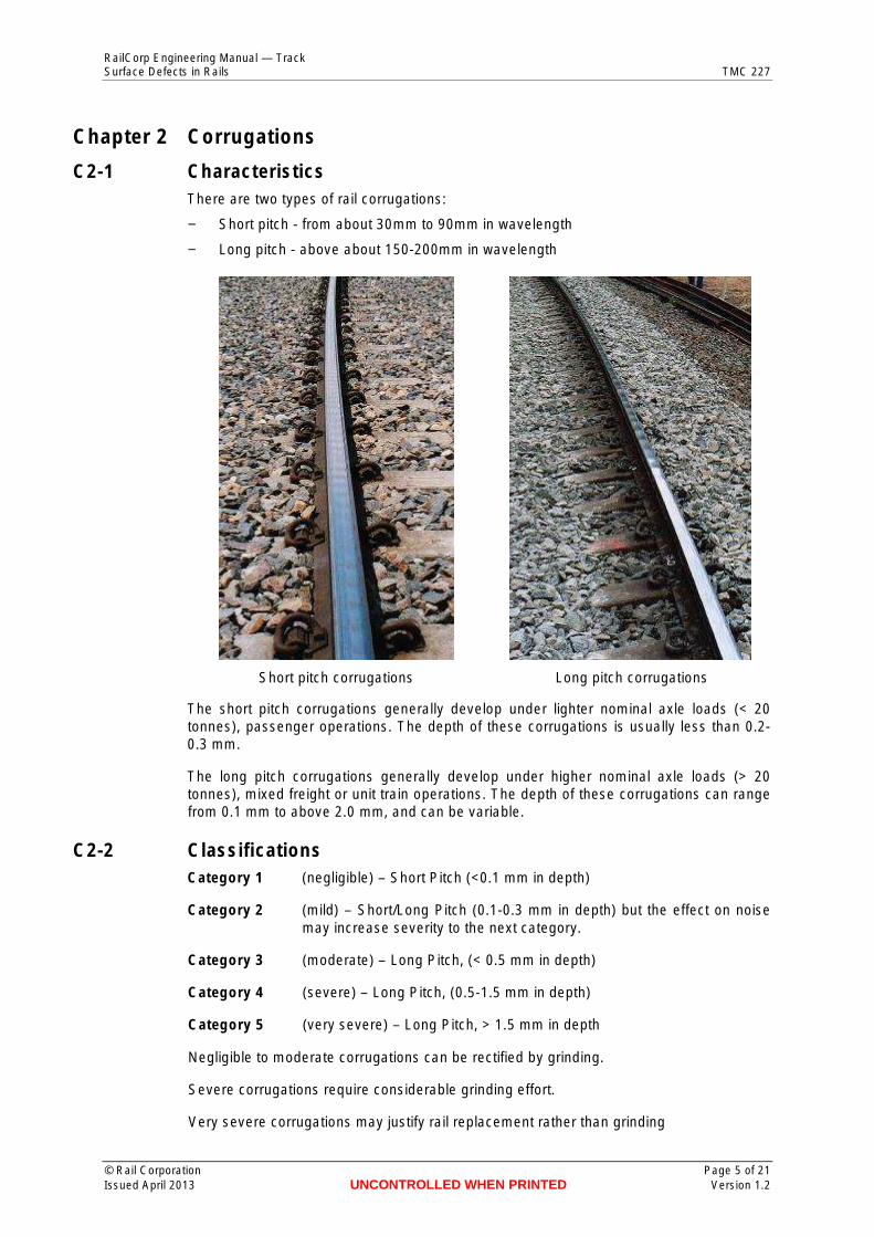
C2-1 Characteristics There are two types of rail corrugations:
− Short pitch - from about 30mm to 90mm in wavelength
− Long pitch - above about 150-200mm in wavelength
Short pitch corrugations Long pitch corrugations
The short pitch corrugations generally develop under lighter nominal axle loads (< 20 tonnes), passenger operations. The depth of these corrugations is usually less than 0.20.3 mm.
The long pitch corrugations generally develop under higher nominal axle loads (> 20 tonnes), mixed freight or unit train operations. The depth of these corrugations can range from 0.1 mm to above 2.0 mm, and can be variable.
C2-2 Classifications Category 1 (negligible) – Short Pitch (<0.1 mm in depth)
Category 2 (mild) – Short/Long Pitch (0.1-0.3 mm in depth) but the effect on noise may increase severity to the next category.
Category 3 (moderate) – Long Pitch, (< 0.5 mm in depth)
Category 4 (severe) – Long Pitch, (0.5-1.5 mm in depth)
Category 5 (very severe) – Long Pitch, > 1.5 mm in depth
Negligible to moderate corrugations can be rectified by grinding.
Severe corrugations require considerable grinding effort.
Very severe corrugations may justify rail replacement rather than grinding
© Rail Corporation Page 5 of 21 Issued April 2013 UNCONTROLLED WHEN PRINTED Version 1.2
RailCorp Engineering Manual — Track Surface Defects in Rails TMC 227
Chapter 3 Checking or Rolling Contact Fatigue (RCF)
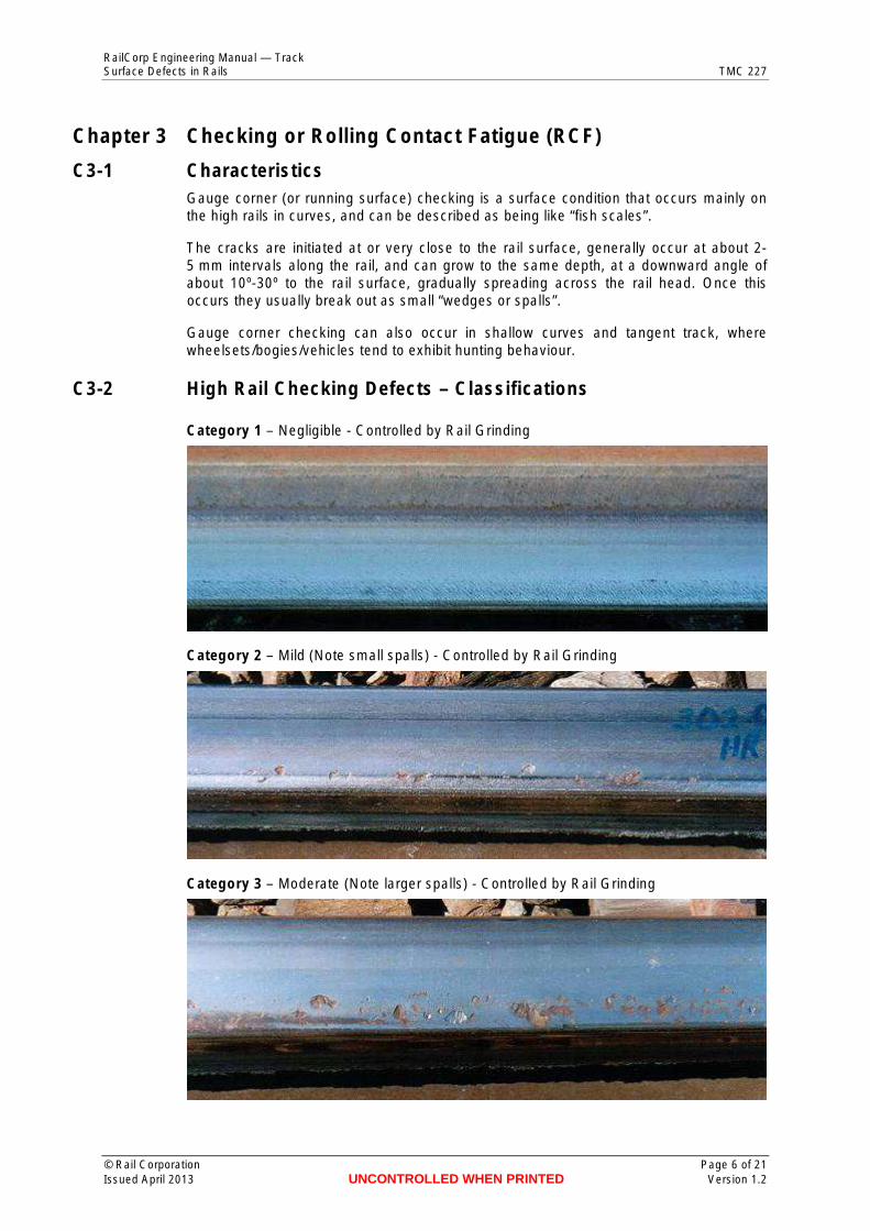
C3-1 Characteristics Gauge corner (or running surface) checking is a surface condition that occurs mainly on the high rails in curves, and can be described as being like “fish scales”.
The cracks are initiated at or very close to the rail surface, generally occur at about 25 mm intervals along the rail, and can grow to the same depth, at a downward angle of about 10º-30º to the rail surface, gradually spreading across the rail head. Once this occurs they usually break out as small “wedges or spalls”.
Gauge corner checking can also occur in shallow curves and tangent track, where wheelsets/bogies/vehicles tend to exhibit hunting behaviour.
C3-2 High Rail Checking Defects – Classifications
Category 1 – Negligible - Controlled by Rail Grinding
Category 2 – Mild (Note small spalls) - Controlled by Rail Grinding
Category 3 – Moderate (Note larger spalls) - Controlled by Rail Grinding
© Rail Corporation Page 6 of 21 Issued April 2013 UNCONTROLLED WHEN PRINTED Version 1.2
RailCorp Engineering Manual — Track Surface Defects in Rails TMC 227
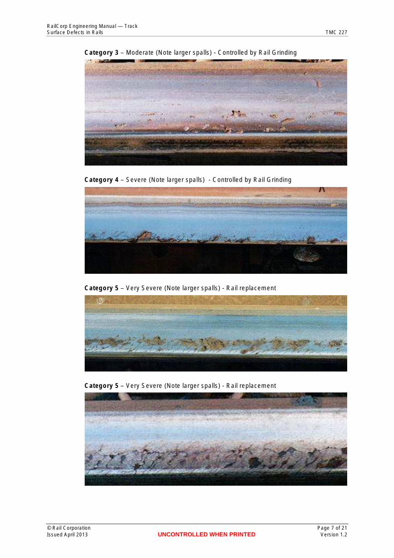
Category 3 – Moderate (Note larger spalls) - Controlled by Rail Grinding
Category 4 – Severe (Note larger spalls) - Controlled by Rail Grinding
Category 5 – Very Severe (Note larger spalls) - Rail replacement
Category 5 – Very Severe (Note larger spalls) - Rail replacement
© Rail Corporation Page 7 of 21 Issued April 2013 UNCONTROLLED WHEN PRINTED Version 1.2
RailCorp Engineering Manual — Track Surface Defects in Rails TMC 227
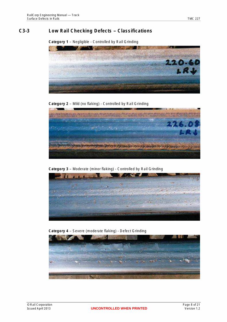
C3-3 Low Rail Checking Defects – Classifications
Category 1 – Negligible - Controlled by Rail Grinding
Category 2 – Mild (no flaking) - Controlled by Rail Grinding
Category 3 – Moderate (minor flaking) - Controlled by Rail Grinding
Category 4 – Severe (moderate flaking) - Defect Grinding
© Rail Corporation Page 8 of 21 Issued April 2013 UNCONTROLLED WHEN PRINTED Version 1.2
RailCorp Engineering Manual — Track Surface Defects in Rails TMC 227
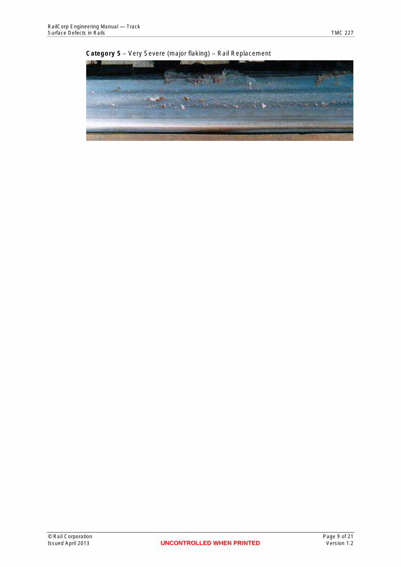
Category 5 – Very Severe (major flaking) – Rail Replacement
© Rail Corporation Page 9 of 21 Issued April 2013 UNCONTROLLED WHEN PRINTED Version 1.2
RailCorp Engineering Manual — Track Surface Defects in Rails TMC 227
Chapter 4 Shelling
C4-1 Characteristics
C4-1.1 Shelling Shelling is an internal defect that initiates at a depth of 2-8 mm below the gauge corner of generally the high rails in curved track (i.e. at much greater depths than gauge corner checking defects).
In the initial stages of development, shelling defects become noticeable in the gauge corner region of the rails as dark spots.
Shelling defects do not form as regularly along the rail as gauge corner checking defects.
Shelling cracks develop on a horizontal or longitudinal plane consistent with the shape of the rail on the gauge corner. The cracks can continue to grow in a longitudinal direction on that plane for some distance at an angle of about 10º-30º to the rail surface, and then either spall out into a shell or turn down and form transverse defects which can continue to grow on a transverse plane and eventually lead to rail failure, if not detected in time.
However, sometimes transverse defects may also directly initiate from irregularities in the steel (inclusions) and grow in a transverse plane, without the need for a prior shelling defect.
Because of their internal nature, transverse defects cannot be visually detected, and hence must rely on regular ultrasonic rail inspection.
C4-2 Classification
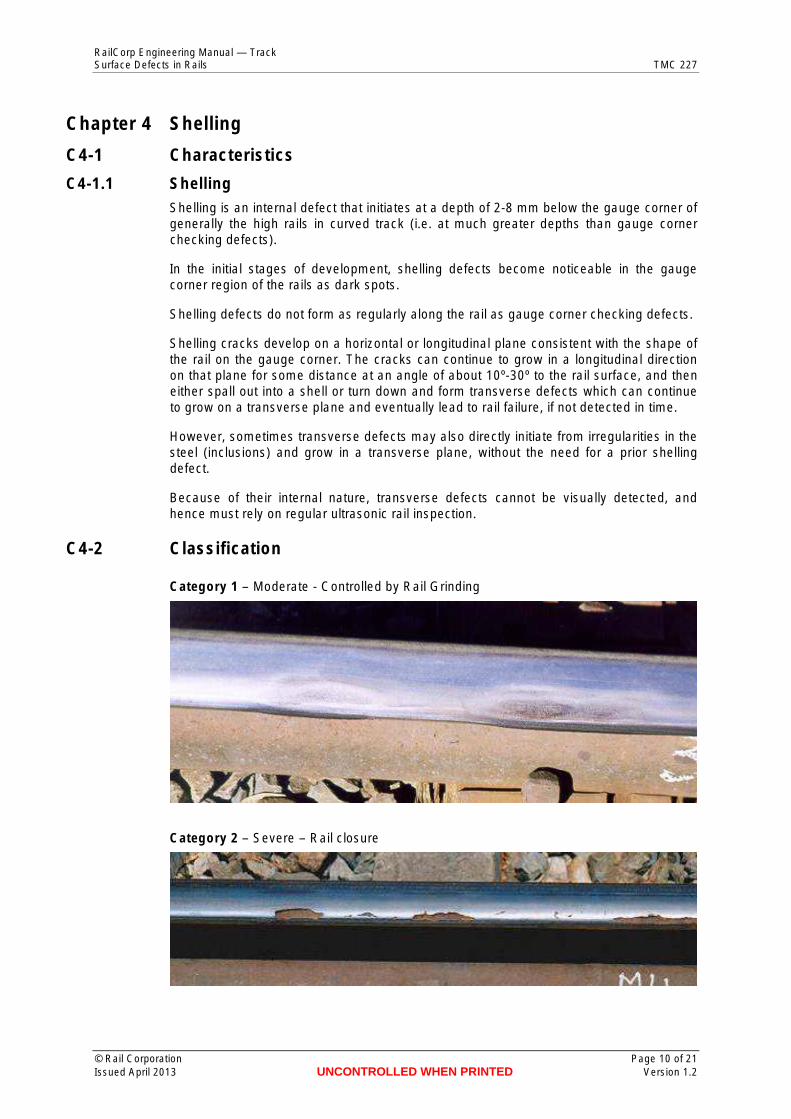
Category 1 – Moderate - Controlled by Rail Grinding
Category 2 – Severe – Rail closure
© Rail Corporation Page 10 of 21 Issued April 2013 UNCONTROLLED WHEN PRINTED Version 1.2
RailCorp Engineering Manual — Track Surface Defects in Rails TMC 227
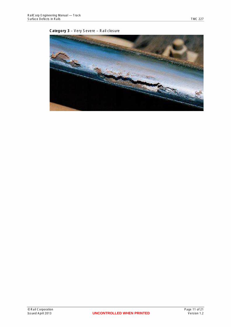
Category 3 – Very Severe – Rail closure
© Rail Corporation Page 11 of 21 Issued April 2013 UNCONTROLLED WHEN PRINTED Version 1.2
RailCorp Engineering Manual — Track Surface Defects in Rails TMC 227
Chapter 5 Squats
C5-1 Characteristics − Can be of two types:
∼ Running surface
∼ Gauge corner (extension of checking defects)
− Widening of wheel/rail running band.
− Cracking/spalling when in moderate to severe stages.
− Generally occur only in 1 rail (unlike wheelburns).
− Generally occur at irregular intervals along the rail (unlike corrugations), either asdiscreet or multiple defects.
− Can develop in all lines within the RailCorp system.
− Can develop in all rail types, but are more prevalent in head hardened rails.
− Can develop in tangent and high rails, but rarely seen in low rails.
− Can develop in track with either timber or concrete sleepers.
− Often develop in switches and uncanted rails in turnouts.
The surface hardness of running surface squats can be much higher than the base hardness of the adjoining and opposite rails, indicating major near surface microstructural changes that are most likely due to wheel/rail traction effects.
Multiple gauge corner squats are particularly prevalent on curves with a moderate radius, in the range 600m to 1500m. These squats are more likely to occur in head hardened rail.
The sub-surface cracks associated with the defects are generally 2-7mm deep. However, indications of deeper cracks have been obtained in a small proportion of defects.
At this stage a very small proportion of squats have developed into transverse defects and broken rails. Squats are a problem because they inhibit ultrasonic rail testing, lead to accelerated degradation of the track structure and cause noise complaints.
C5-2 Classification
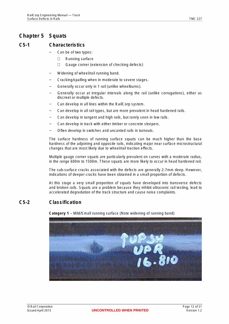
Category 1 – Mild/Small running surface (Note widening of running band)
© Rail Corporation Page 12 of 21 Issued April 2013 UNCONTROLLED WHEN PRINTED Version 1.2
RailCorp Engineering Manual — Track Surface Defects in Rails TMC 227
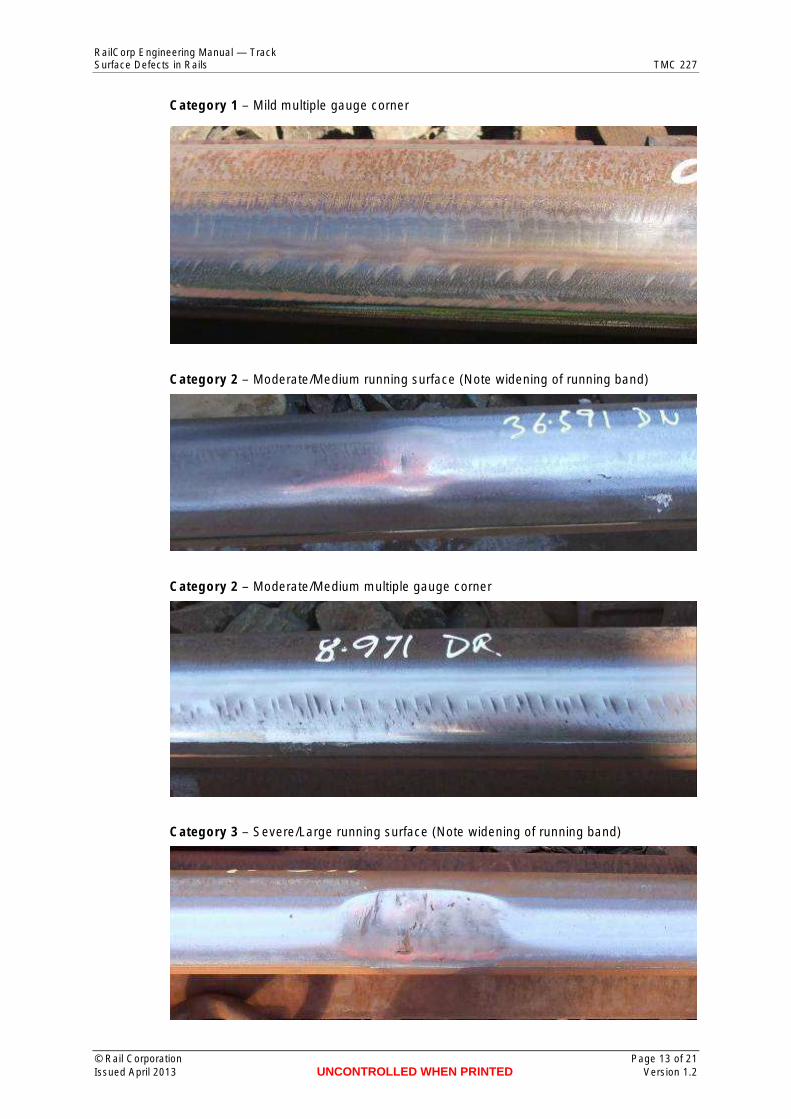
Category 1 – Mild multiple gauge corner
Category 2 – Moderate/Medium running surface (Note widening of running band)
Category 2 – Moderate/Medium multiple gauge corner
Category 3 – Severe/Large running surface (Note widening of running band)
© Rail Corporation Page 13 of 21 Issued April 2013 UNCONTROLLED WHEN PRINTED Version 1.2
RailCorp Engineering Manual — Track Surface Defects in Rails TMC 227
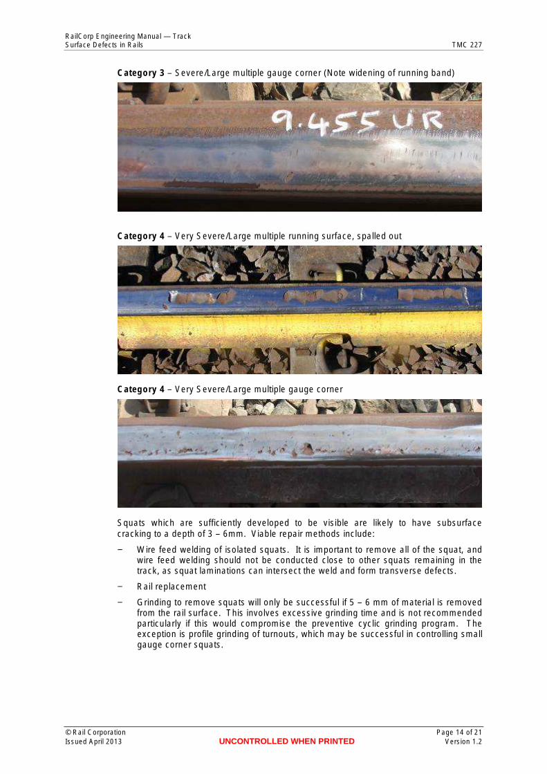
Category 3 – Severe/Large multiple gauge corner (Note widening of running band)
Category 4 – Very Severe/Large multiple running surface, spalled out
Category 4 – Very Severe/Large multiple gauge corner
Squats which are sufficiently developed to be visible are likely to have subsurface cracking to a depth of 3 – 6mm. Viable repair methods include:
− Wire feed welding of isolated squats. It is important to remove all of the squat, and wire feed welding should not be conducted close to other squats remaining in the track, as squat laminations can intersect the weld and form transverse defects.
− Rail replacement
− Grinding to remove squats will only be successful if 5 – 6 mm of material is removed from the rail surface. This involves excessive grinding time and is not recommended particularly if this would compromise the preventive cyclic grinding program. The exception is profile grinding of turnouts, which may be successful in controlling small gauge corner squats.
© Rail Corporation Page 14 of 21 Issued April 2013 UNCONTROLLED WHEN PRINTED Version 1.2
RailCorp Engineering Manual — Track Surface Defects in Rails TMC 227
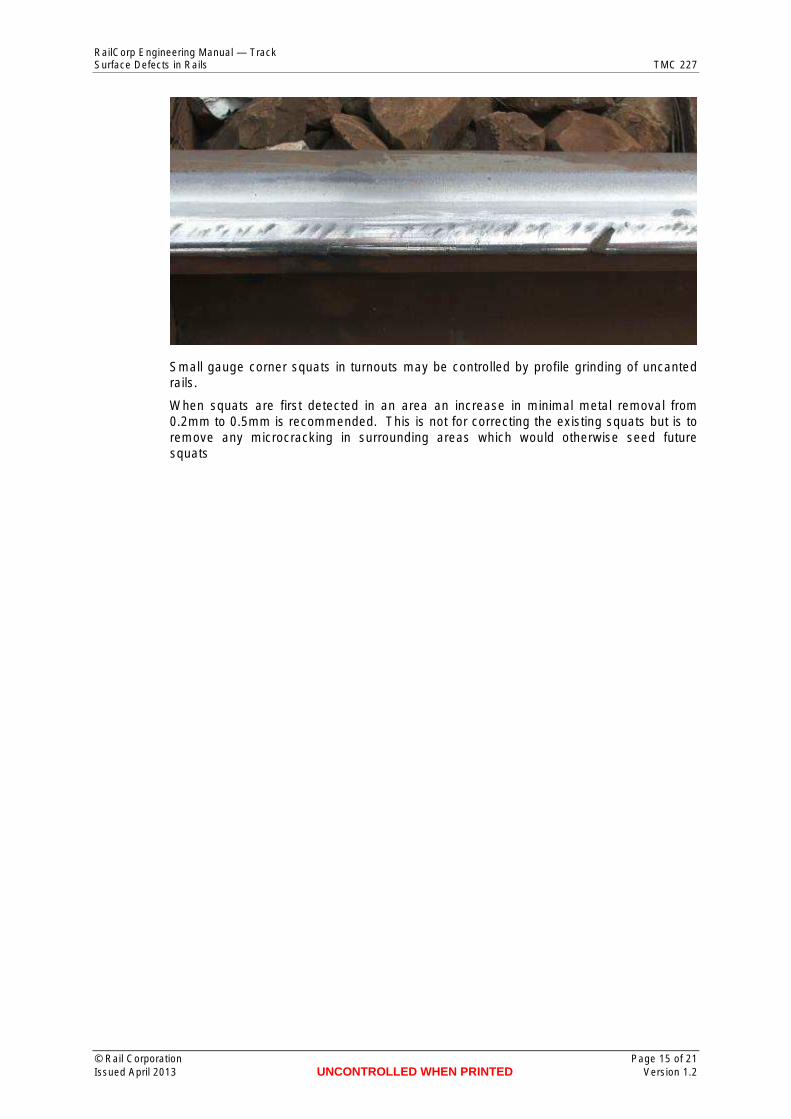
Small gauge corner squats in turnouts may be controlled by profile grinding of uncanted rails.
When squats are first detected in an area an increase in minimal metal removal from 0.2mm to 0.5mm is recommended. This is not for correcting the existing squats but is to remove any microcracking in surrounding areas which would otherwise seed future squats
© Rail Corporation Page 15 of 21 Issued April 2013 UNCONTROLLED WHEN PRINTED Version 1.2
RailCorp Engineering Manual — Track Surface Defects in Rails TMC 227
Chapter 6 Wheelslip Surface Defects
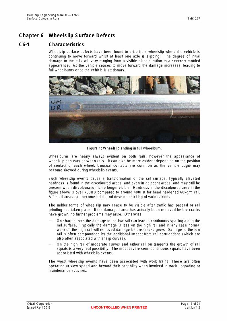
C6-1 Characteristics Wheelslip surface defects have been found to arise from wheelslip where the vehicle is continuing to move forward whilst at least one axle is slipping. The degree of initial damage to the rails will vary ranging from a visible discolouration to a severely mottled appearance. As the vehicle ceases to move forward the damage increases, leading to full wheelburns once the vehicle is stationary.
Figure 1: Wheelslip ending in full wheelburn.
Wheelburns are nearly always evident on both rails, however the appearance of wheelslip can vary between rails. It can also be more evident depending on the position of contact of each wheel. Unusual contacts are common as the vehicle bogie may become skewed during wheelslip events.
Such wheelslip events cause a transformation of the rail surface. Typically elevated hardness is found in the discoloured areas, and even in adjacent areas, and may still be present when discolouration is no longer visible. Hardness in the discoloured area in the figure above is over 700HB compared to around 400HB for head hardened 60kg/m rail. Affected areas can become brittle and develop cracking of various kinds.
The milder forms of wheelslip may cease to be visible after traffic has passed or rail grinding has taken place. If the damaged area has actually been removed before cracks have grown, no further problems may arise. Otherwise:
− On sharp curves the damage to the low rail can lead to continuous spalling along the rail surface. Typically the damage is less on the high rail and in any case normal wear on the high rail will removed damage before cracks grow. Damage to the low rail is often compounded by the additional impact from rail corrugations (which are also often associated with sharp curves).
− On the high rail of moderate curves and either rail on tangents the growth of rail squats is a very real possibility. The most severe semi-continuous squats have been associated with wheelslip events.
The worst wheelslip events have been associated with work trains. These are often operating at slow speed and beyond their capability when involved in track upgrading or maintenance activities.
© Rail Corporation Page 16 of 21 Issued April 2013 UNCONTROLLED WHEN PRINTED Version 1.2
RailCorp Engineering Manual — Track Surface Defects in Rails TMC 227
Figure 2: Continuous squats on the high rail arising from wheelslip event.
C6-2 Examples
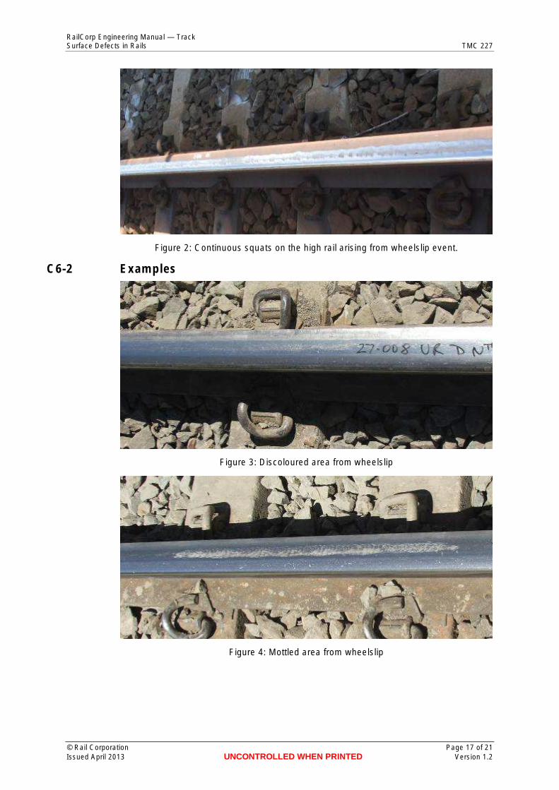
Figure 3: Discoloured area from wheelslip
Figure 4: Mottled area from wheelslip
© Rail Corporation Page 17 of 21 Issued April 2013 UNCONTROLLED WHEN PRINTED Version 1.2
RailCorp Engineering Manual — Track Surface Defects in Rails TMC 227
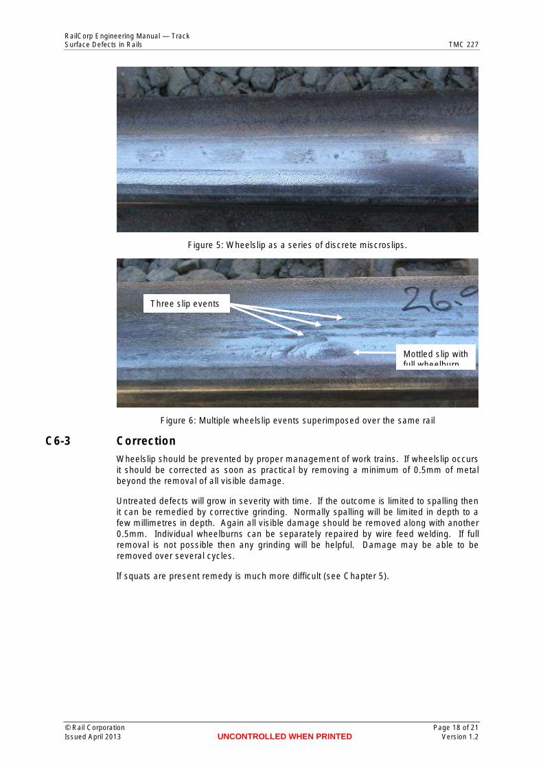
Figure 5: Wheelslip as a series of discrete miscroslips.
Mottled slip with full wheelburn
Three slip events
Figure 6: Multiple wheelslip events superimposed over the same rail
C6-3 Correction Wheelslip should be prevented by proper management of work trains. If wheelslip occurs it should be corrected as soon as practical by removing a minimum of 0.5mm of metal beyond the removal of all visible damage.
Untreated defects will grow in severity with time. If the outcome is limited to spalling then it can be remedied by corrective grinding. Normally spalling will be limited in depth to a few millimetres in depth. Again all visible damage should be removed along with another 0.5mm. Individual wheelburns can be separately repaired by wire feed welding. If full removal is not possible then any grinding will be helpful. Damage may be able to be removed over several cycles.
If squats are present remedy is much more difficult (see Chapter 5).
© Rail Corporation Page 18 of 21 Issued April 2013 UNCONTROLLED WHEN PRINTED Version 1.2

RailCorp Engineering Manual — Track Surface Defects in Rails TMC 227
Chapter 7 Wheelburns
C7-1 Classification
Category 1 – Small (< 1mm depth). Recoverable by rail grinding
Category 2 – Medium (1-2mm depth). Weld repair.
Category 2 – Medium (1.0-2.0mm Depth)
© Rail Corporation Page 19 of 21 Issued April 2013 UNCONTROLLED WHEN PRINTED Version 1.2
RailCorp Engineering Manual — Track Surface Defects in Rails TMC 227
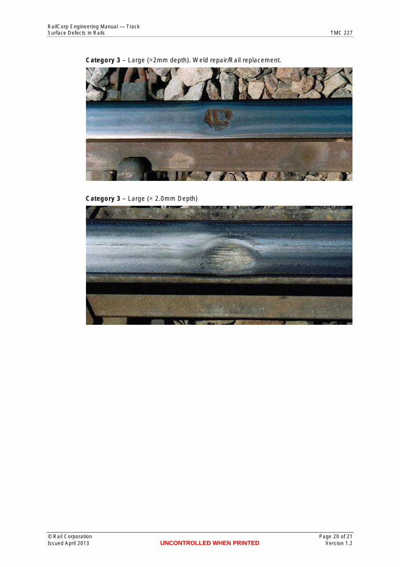
Category 3 – Large (>2mm depth). Weld repair/Rail replacement.
Category 3 – Large (> 2.0mm Depth)
© Rail Corporation Page 20 of 21 Issued April 2013 UNCONTROLLED WHEN PRINTED Version 1.2
RailCorp Engineering Manual — Track Surface Defects in Rails TMC 227
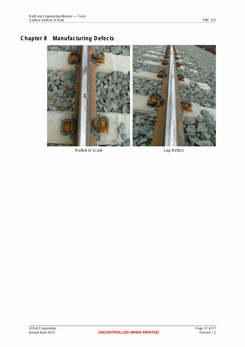
Chapter 8 Manufacturing Defects
Rolled in Scale Lap Defect
© Rail Corporation Page 21 of 21 Issued April 2013 UNCONTROLLED WHEN PRINTED Version 1.2


![TMC,Kumta · Title: Microsoft PowerPoint - TMC,Kumta [Read-Only] Author: tmc Created Date: 12/27/2016 5:54:16 PM](https://img.pdfslide.us/doc/110x75/5f35fb362efc86474f2e2263/tmc-title-microsoft-powerpoint-tmckumta-read-only-author-tmc-created-date.jpg)