Embed Size (px)
Citation preview

Engineering Manual Track
TMC 222
RAIL WELDING
Version 4.7
Issued June 2012
Owner: Chief Engineer Track
Approved by:
Andrew Wilson Technical Specialist Wheel/Rail
Authorised by:
Malcolm Kerr Chief Engineer Track
Disclaimer This document was prepared for use on the RailCorp Network only. RailCorp makes no warranties, express or implied, that compliance with the contents of this document shall be sufficient to ensure safe systems or work or operation. It is the document user’s sole responsibility to ensure that thecopy of the document it is viewing is the current version of the document as in use by RailCorp. RailCorp accepts no liability whatsoever in relation to the use of this document by any party, and RailCorp excludes any liability which arises in any manner by the use of this document.
Copyright The information in this document is protected by Copyright and no part of this document may be reproduced, altered,stored or transmitted by any person without the prior consent of RailCorp.
Engi
neer
ing
Man
ual
UNCONTROLLED WHEN PRINTED Page 1 of 103

RailCorp Engineering Manual — Track Rail Welding TMC 222
Document control Version Date Summary of change
1.0 October 2006 First issue as a RailCorp document. Includes content from RAP.5391, RAP.5394, RTS.3602, RTS.3733, RTS.3734, CTN 01/11, CTN 04/14, CTN 05/02, CTN 06/15, CTN 06/20
2.0 April 2007 Removal of requirement for use of masks near multi-use crucibles; removal of restriction on adjacent welds; removal of requirement to re-cut HH rail after 30 mins; removal of restriction on welding near heat numbers for new rail; clarification of post weld actions; inclusion of requirement not to cool with water; clarification of weld alignment tolerances and method of assessment; changes to welding codes; Additional Quick Reference information; Added restriction on welding of swingnose crossings
3.0 October 2007 Includes mandatory use of PDAs, reporting of defective components, additional competency requirements for repair of manganese crossings, change of regulator type for welds; check of rail damage before welding and approved use of robotic welder for repair of manganese crossings
4.0 May 2008 C4-7 – Addition of Thermit One Shot crucibles to approved welding process. Section C4-16.8 and C4-18.1 – Changes to igniter material and method.
4.1 December 2008 Section C2-2 - Addition of requirements to remove adjacent squats when undertaking wirefeed head repair welds; Added heading Section C4-23 – Weld Alignment Acceptance Limits and renumbering of following sections: Added welding codes for new weld types in C4-27, Table 4; Added Acceptance limits to Section C5-5: Added new Section C5-6 detailing new longitudinal crossing profile and method of measurement: Renumbered following sections: Added reference to Acceptance limits in Section C5-8.5.
4.2 May 2009 Complete document – Format Change; A-4.3-1.14 Quick Reference Table – correction of incorrect Wide Gap measurement
4.3 December 2009 Title changes to reflect organisational change; C4-8.4 – Additional precautions regarding welding in tunnels from CTN 09/04; C4-8.6 – Additional requirements regarding welding in wet weather from CTN 09/04; C4-23 -Straightness requirements added; Addition of use of rail tensor to table 3; C4-29 – restrictions on placing welds directly on slab track; Appendix 4.1 Addition of use of rail tensor to Weld Return; C5-6.3 – Addition of Transverse Crossing profile; C6-2 – Updating of colour coding
4.4 July 2010 C4-6 - Addition of clarification of relevant editions of Australian Standards; – Correction of error in Table 6 – Change 47kg rail (AS 1921) to 47kg rail (AS 1981); C4-7 - Updating list of Approved Aluminothermic Welding processes C4-10 & C4-12 – Reinforcement of restriction on operating rail vehicles over unsecured rail ends; C4-17
© Rail Corporation Page 2 of 103 Issued June 2012 UNCONTROLLED WHEN PRINTED Version 4.7

RailCorp Engineering Manual — Track Rail Welding TMC 222
& C4-18 - Changes to suit restriction of approved welding processes to Single Use crucibles; C4-27 – Introduction of alternative Welding Return Form WR2; App 4.1 - Additional Welding Return Form WR2 to suit manual entry of data; App 4.2 - Changes to suit restriction of approved welding processes to Single Use crucibles; App 4.5 - Changes to suit restriction of approved welding processes to Single Use crucibles
4.5 February 2011 C4-7 – Additional approved junction weld; C4-12.3, C4-24 – change of logo on weld sticker; C4-27 Table 3 - only closures less than 6m in length need be crowed; App 4.1 - Welding Return - only closures less than 6m in length need be crowed; C5 - Correction of error in Figure 48 and 51; C5-10 – change of logo on weld sticker
4.6 August 2011 C1-4 - Reference change; C3 - Competencies updated to current National Competencies; C4-3, C4-11, C4-15.2, C417, C4-17.5, C4-18, C4-18.1, C4-19, C4-20, C4-21.1 – Removal of detailed PPE requirements, replacement with reference to SWMS; C4-4 Deletion of first aid requirements; C4-24 – added requirement to mark new aluminothermic welds with pink fluorescent paint; C5-3, C5-3.2 - Removal of detailed PPE requirements, replacement with reference to SWMS; C6-2 – Updated personnel authorised to inspect Oxy-Fuel Gas Equipment
4.7 June 2012 Changes detailed in Chapter Revisions
Summary of changes from previous version Summary of change Chapter
Control changes Control Pages
Reformatted to new template – Page numbering converted to continuous numbering. Separate document control on individual chapters removed
All
Addition of guidance on wirefeed repair / replacement of crossings (includes content from CTN 12/05).
C5-7.1.1
© Rail Corporation Page 3 of 103 Issued June 2012 UNCONTROLLED WHEN PRINTED Version 4.7

RailCorp Engineering Manual — Track Rail Welding TMC 222
Contents
Chapter 1 General...........................................................................................................................6
C1-1 Purpose...........................................................................................................................6
C1-2 Context............................................................................................................................6
C1-3 How to read the Manual..................................................................................................6
C1-4 References......................................................................................................................7
Chapter 2 Management Requirements.........................................................................................8
C2-1 Managers in charge of welders.......................................................................................8
C2-2 Team Managers..............................................................................................................9
C2-3 Rail Welding Inspectors ................................................................................................10
C2-4 Contract welders ...........................................................................................................10
C2-5 Special arrangements for testing..................................................................................10
Chapter 3 Competencies .............................................................................................................11
Chapter 4 Aluminothermic Welding ...........................................................................................12
C4-1 Introduction ...................................................................................................................12
C4-2 Records.........................................................................................................................12
C4-3 Personal Safety Equipment ..........................................................................................12
C4-4 Transport and storage of ignition tapes ........................................................................13
C4-5 Rails approved for welding ...........................................................................................13
C4-6 Approved welding processes........................................................................................14
C4-7 Welding requirements...................................................................................................14
C4-8 Ten Golden Rules.........................................................................................................18
C4-9 Preliminary Work...........................................................................................................19
C4-10 Cutting a gap for welding ..............................................................................................20
C4-11 Welding a closure into track..........................................................................................22
C4-12 Rail end condition .........................................................................................................23
C4-13 Lining ends for welding .................................................................................................24
C4-14 Fitting moulds to the rail................................................................................................27
C4-15 The Crucible..................................................................................................................28
C4-16 Preheating.....................................................................................................................29
C4-17 The Weld.......................................................................................................................30
C4-18 Break down and cut off of weld.....................................................................................32
C4-19 Cutting off the excess head metal ................................................................................34
C4-20 Disturbing the weld .......................................................................................................36
C4-21 Finishing off the weld ....................................................................................................38
C4-22 Weld Alignment Acceptance Limits ..............................................................................39
C4-23 Visual inspection of welds.............................................................................................42
C4-24 Identifying aluminothermic welds..................................................................................42
C4-25 Before leaving the site ..................................................................................................43
C4-26 Recording aluminothermic welds..................................................................................43
C4-27 Reporting aluminothermic welds...................................................................................46
C4-28 Welding on slab track ...................................................................................................46
Appendix 4.1 Welding Return ...........................................................................................................47
Appendix 4.2 Thermit Welding Methods..........................................................................................49
A-4.2-1 Thermit SKVE method ..................................................................................................49
A-4.2-2 Thermit Head Repair Weld ...........................................................................................55
© Rail Corporation Page 4 of 103 Issued June 2012 UNCONTROLLED WHEN PRINTED Version 4.7

RailCorp Engineering Manual — Track Rail Welding TMC 222
Appendix 4.3 Railtech Welding Methods .........................................................................................57
A-4.3-1 Railtech PLKCJ.............................................................................................................57
Appendix 4.4 Hot Work Crate............................................................................................................62
Appendix 4.5 Care and Maintenance of Welding Equipment ........................................................63
A-4.5-1 General .........................................................................................................................63
A-4.5-2 Single use crucible........................................................................................................63
A-4.5-3 Preheating torch............................................................................................................63
Appendix 4.6 Welding Process – Troubleshooting Guide .............................................................64
Appendix 4.7 Non-Conformance Report..........................................................................................66
Chapter 5 Wire Feed Welding......................................................................................................67
C5-1 Description ....................................................................................................................67
C5-2 Records.........................................................................................................................67
C5-3 Safety requirements......................................................................................................67
C5-4 General requirements ...................................................................................................67
C5-5 Rail Head Repair Acceptance standards......................................................................70
C5-6 Repairing Crossing Profile ............................................................................................71
C5-7 Repairing crossings ......................................................................................................77
C5-8 Repairing wheel burns ..................................................................................................83
C5-9 Speed of traffic over worksite .......................................................................................87
C5-10 Identifying wire feed welds............................................................................................87
C5-11 Recording wire feed welds............................................................................................87
C5-12 Reporting wire feed welds ............................................................................................88
Appendix 5.1 Wire Feed Welding Return .........................................................................................89
Appendix 5.2 Specifications..............................................................................................................90
A-5.2-1 Lincore 33 .....................................................................................................................90
A-5.2-2 TN3-0 ............................................................................................................................90
A-5.2-3 B3-0 ..............................................................................................................................90
A-5.2-4 Oxy LPG Gouging.........................................................................................................90
Appendix 5.3 Welding machine - Lincoln 400 AS ...........................................................................91
A-5.3-1 Current (AMPS) ............................................................................................................91
A-5.3-2 Voltage..........................................................................................................................91
A-5.3-3 Wire speed....................................................................................................................92
A-5.3-4 Visible stickout ..............................................................................................................92
Appendix 5.4 Trouble shooting.........................................................................................................93
A-5.4-1 To eliminate porosity.....................................................................................................93
A-5.4-2 To eliminate ropy convex bead.....................................................................................93
A-5.4-3 To eliminate splatter .....................................................................................................93
A-5.4-4 To eliminate stubbing....................................................................................................93
A-5.4-5 To eliminate poor penetration .......................................................................................94
A-5.4-6 To eliminate arc blow....................................................................................................94
Chapter 6 Inspection of Oxy-Fuel Gas Equipment....................................................................95
C6-1 Introduction ...................................................................................................................95
C6-2 Requirements for testing...............................................................................................95
C6-3 Leak and function testing procedure.............................................................................95
© Rail Corporation Page 5 of 103 Issued June 2012 UNCONTROLLED WHEN PRINTED Version 4.7

RailCorp Engineering Manual — Track Rail Welding TMC 222
Chapter 1 General
C1-1 Purpose This manual provides requirements, processes and guidelines for the installation and repair of rail using aluminothermic and wirefeed welding techniques.
C1-2 Context The manual is part of RailCorp's engineering standards and procedures publications. More specifically, it is part of the Civil Engineering suite that comprises standards, installation and maintenance manuals and specifications.
Manuals contain requirements, process and guidelines for the management of track assets and for carrying out examination, construction, installation and maintenance activities.
The manual is written for the persons undertaking installation and maintenance activities.
It also contains management requirements for Civil Maintenance Engineers and Team Managers needing to know what they are required to do to manage the rail welding activities on their areas, and production managers needing to know what they are required to do to manage the renewal activity their teams are undertaking.
This manual is part of a series of seven (7) rail manuals
• TMC 221 – Rail Installation & Repair • TMC 222 – Rail Welding • TMC 223 – Rail Adjustment • TMC 224 – Rail Defects & Testing • TMC 225 – Rail Grinding • TMC 226 – Rail Defects Handbook • TMC 227 – Surface Defects in Rails
C1-3 How to read the Manual The best way to find information in the manual is to look at the Table of Contents starting on page 4. Ask yourself what job you are doing? The Table of Contents is written to reflect work activities.
When you read the information, you will not need to refer to RailCorp Engineering standards. Any requirements from standards have been included in the sections of the manual and shown like this:
The following Design requirement is extracted from RailCorp standard ESC 220 Welds MUST NOT be installed when exposed to moisture (rain, fog etc).
Reference is, however, made to other Manuals.
© Rail Corporation Page 6 of 103 Issued June 2012 UNCONTROLLED WHEN PRINTED Version 4.7

RailCorp Engineering Manual — Track Rail Welding TMC 222
C1-4 References
C1-4.1 Australian and International Standards
AS 4839 (2001) – The safe use of portable and mobile oxy-fuel gas systems for welding, cutting, heating and allied processes
C1-4.2 RailCorp Documents
ESC 220 – Rail and Rail Joints
TMC 001 – Civil Technical Competencies and Engineering Authority
TMC 202 – Track Fundamentals
TMC 221 – Rail Installation & Repair
TMC 223 – Rail Adjustment
TMC 224 – Rail Defects & Testing
TMC 501 – Bushfire Hazard Management
SPC 201 – Measurement Gauges
RailCorp Safety Management System
© Rail Corporation Page 7 of 103 Issued June 2012 UNCONTROLLED WHEN PRINTED Version 4.7

RailCorp Engineering Manual — Track Rail Welding TMC 222
Chapter 2 Management Requirements
C2-1 Managers in charge of welders The manager in charge of the welder is accountable for the performance of his/her welders. He/she must have systems in place to:
For aluminothermic and wire feed welds
1. ensure only competent, licensed welders are used,
2. ensure only approved, tagged, equipment is used,
3. provide or arrange for a Hot Work Authority in Total Fire Bans,
4. ensure that all welds have been entered into RailCorp's SmartWeld database.
Normally the welders will enter the data for each weld into their PDAs and upload this information directly into the SmartWeld database. If, however, this is not possible for some reason (PDA breakdown etc) make sure that a paper welding return is completed and uploaded into the SmartWeld database.
5. ensure that all the welder’s welds have been tested,
6. maintain an up-to-date record the welder’s defect rate,
7. manage the welder’s on-going performance.
Defective components
New or recently installed track components or tools are sometimes defective, or otherwise fail to meet specified requirements. In some circumstances it will be necessary to recall the product and take action with the supplier.
If you are notified by your field staff that potentially defective components or tools have been supplied:
1. Raise an NCR. (NCR Form attached as Appendix 4.7).
2. Conduct an assessment of the non-conforming product by inspection and, if practical, test sample at least 2-3 other such items from the same batch.
This will help to determine the extent of the problem.
3. Forward the NCR to:
Ilya Soyfer, Logistics Support Engineer in Track Services(phone 8922 1148 (2 1148)fax 8922 1726 (2 1726) email [email protected].
4. If there is any immediate concern, contact should be made by phone.
5. Track Services will investigate the failure and its implications and take other actions as required. This may include:
6. Quarantine all product to avoid installation
© Rail Corporation Page 8 of 103 Issued June 2012 UNCONTROLLED WHEN PRINTED Version 4.7

RailCorp Engineering Manual — Track Rail Welding TMC 222
7. Allow installed product to remain in track under special conditions
8. Remove all product from track etc.
If this occurs official notification will be by the issue of a Civil Technical Note
C2-2 Team Managers Team Managers are accountable for the condition of track in their area, including the condition of welds. They must:
For aluminothermic and wire feed welds
1. Monitor the progress of weld testing to ensure that welds are tested within 14 days.
2. Check that weld data is uploaded into SmartWeld for ALL welds in his/her area (from his/her own welders and from welders from outside his/her area).
3. Maintain updated records of welders under his/her control or forward a copy of the results to the manager in charge of the welder.
For aluminothermic welds
1. Arrange for ultrasonic testing of aluminothermic welds within 14 days after the work has been completed.
For wire feed welds
1. Arrange for locations proposed for wire feed welding to be inspected to determine if the repair is viable.
Check what material the crossing is made from. RailCorp Engineering Manual TMC 202 – Track Fundamentals gives guidance on checking material type. Check both the nose and wing material. They may not be the same material.
Manganese crossing noses cannot currently be repaired in track without the use of the robotic welder.
Chrome Vanadium crossing noses can be repaired using normal wirefeed welding process.
2. If wirefeed welding is planned to remove rail squat defects, make sure that all squats in the immediate vicinity are removed as part of the work. If this is not undertaken the heat affected zone of the wire feed weld may cause an adjacent squat lamination to turn down, leading to a potential broken rail.
3. Arrange for ultrasonic testing of proposed wire feed repair locations 1 week prior to the repair. The Rail Flaw Detection officer will provide a report on the depth and length all defect indications.
4. Confirm that there are no reportable rail defects or any defects below 12m from the surface. Otherwise these crossings cannot be welded.
5. Provide the welders including contract welders with information confirming:
o the crossing and wing rail material ie is it carbon steel, chrome vanadium etc.,
© Rail Corporation Page 9 of 103 Issued June 2012 UNCONTROLLED WHEN PRINTED Version 4.7

RailCorp Engineering Manual — Track Rail Welding TMC 222
o that the crossing has been ultrasonically tested and details of any defects present have been provided,
6. Arrange for track repairs to the proposed repair site prior to the repair.
7. Arrange for ultrasonic testing of wire feed repair locations within 14 days after the work has been completed.
8. Arrange for follow up work to be completed within 2 weeks after the repair.
9. Keep a record of the location of all wire feed welds performed, the person who performed them and the reasons they were performed. The results of ultrasonic tests shall also be included in the records. This information is available in SmartWeld.
C2-3 Rail Welding Inspectors RailCorp’s Welding Inspectors monitor the performance of welders and of welding equipment and consumables. To assist in maintaining the quality of the product and to ensure correct procedures are being observed, Rail Welding Inspectors (or equivalent) are required to regularly inspect the work of all welders.
Using the information collated from weld data entered into SmartWeld and other sources, the Inspectors provide advice to Civil Maintenance Engineers on welder performance issues, and to the Chief Engineer Track on the adequacy of training, engineering practices and equipment and material specifications.
The Inspectors have the authority to instruct welders in all matters of both a practical and technical nature related to field welding and adjustment of rails.
C2-4 Contract welders Where contract welders are engaged the field manager (e.g. Team Leader, Project Supervisor) in RailCorp in charge of the contractor's work is responsible for the activities of the "Manager in charge of the welder" (C2-1 above) and in addition for ensuring:
• the welders engaged are competent and hold a current licence, • the welders engaged have a satisfactory weld performance history, • weld data for each weld has been appropriately entered by the welders into
SmartWeld, and • the outcomes of the weld testing are forwarded to the company from which the
welder was hired.
C2-5 Special arrangements for testing In some cases, such as for new construction work, testing of welds may be carried out by staff within the construction group. Such arrangements are permissible provided that there is a written agreement between the construction group and maintenance organisation and provided the testing and control outcomes in this manual are achieved.
© Rail Corporation Page 10 of 103 Issued June 2012 UNCONTROLLED WHEN PRINTED Version 4.7

RailCorp Engineering Manual — Track Rail Welding TMC 222
Chapter 3 Competencies NOTE: These competencies may enable activities to be carried out in other manuals. For a comprehensive list of all activities that are covered by a given competency see Engineering Manual TMC 001 – Civil Technical Competencies and Engineering Authority.
To carry out this work You need these competencies
Aluminothermic welding TLIW3015A - Weld rail using aluminothermic welding process
Grind rails TLIW2012A - Grind rails OR TLIW3015A - Weld rail using aluminothermic welding process
Certify aluminothermic welds during or after welding
TLIW3015A - Weld rail using aluminothermic welding process
Wire feed welding TLIW3014A - Weld rail using electric welding process
Wire feed welding of manganese crossings
TLIW3014A - Weld rail using electric welding process
AND Additional training in the use of the "Robotic Welder"
Certify wirefeed welds during or after welding
TLIW3014A - Weld rail using electric welding process
Certify plain track during or after welding has been done (sleepers restored, fastenings, geometry etc.)
TLIX2509A - Install rail AND TLIB3094A - Check and repair track geometry
Certify turnouts and special trackwork during or after welding has been done (sleepers restored, fastenings, geometry etc.)
Certify plain track during or after welding competencies
AND TLIB9509A - Check and repair points and crossings
Inspect and test oxygen /LPG or acetylene equipment.
Authorised RailCorp personnel (See Chapter 6).
© Rail Corporation Page 11 of 103 Issued June 2012 UNCONTROLLED WHEN PRINTED Version 4.7

RailCorp Engineering Manual — Track Rail Welding TMC 222
Chapter 4 Aluminothermic Welding
C4-1 Introduction This chapter details the approved processes for aluminothermic welding.
The body of the chapter provides general requirements, including safety issues, and the common parts of all processes. In addition there are six (6) appendices
Appendix 4.1: Welding Return
Appendix 4.2: Thermit Welding Methods – Special Instructions
Provides requirements for use with Thermit processes including gap, oxy and LPG pressure, preheat time, strip down and cut off time, finish grind time etc. for SKVE standard, junction and wide gap Welds.
The Thermit Head Repair Welding process is also detailed
Appendix 4.3: Railtech Welding Methods – Special Instructions
Provides requirements for use with Railtech processes including gap, oxy and LPG pressure, preheat time, strip down and cut off time, finish grind time etc. for PLKCJ welds
Appendix 4.4: Hot Work Crate
Appendix 4.5: Care and Maintenance of Welding Equipment
Appendix 4.6: Welding Process – Troubleshooting Guide
C4-2 Records Records of all welding performed shall be maintained in RailCorp's SmartWeld Web based information system. All welders, whether RailCorp employees or contractors must use hand held PDAs to enter data. Failure to do so may result in loss of authority to weld on RailCorp infrastructure.
Enter data into the SmartWeld application by entering data into the field based SmartWeld application and uploading it to the SmartWeld web application. Forms are made available only for use in the event of failure of field PDAs. If forms are used, the manual records for each weld shall be entered into the SmartWeld web application within 2 days.
C4-3 Personal Safety Equipment When you are conducting aluminothermic welding operations, you MUST wear appropriate Personal Protective Equipment (PPE). Your welder's assistant and other personnel on site (where necessary) must also wear the PPE. Requirements for PPE are contained in the relevant Safe Work Method Statements (SWMs) in the RailCorp Safety Management System.
© Rail Corporation Page 12 of 103 Issued June 2012 UNCONTROLLED WHEN PRINTED Version 4.7

RailCorp Engineering Manual — Track Rail Welding TMC 222
C4-4 Transport and storage of ignition tapes Ignition tapes should be stored and transported in the same type of container as detonators and have the following signage attached:
"DANGER FLAMMABLE MATERIAL"
"STORE AWAY FROM PORTIONS"
C4-5 Rails approved for welding The following rails approved for welding are extracted from RailCorp standard ESC 220
Rails approved for aluminothermic welding are detailed below. For the rail sizes nominated in the table, rail manufactured to Australian standards published since the editions listed below are also approved for welding
60 kg AS. 1981
60 kg AS. 1981
53 kg AS. 1981
107 lb AS. 1936
103 lb AS. 1936
100 lb AS. 1928
47 kg AS. 1981
94 lb AS. 1937
90 lb AS. 1928
90 lb AS. 1925
90 lb A.S. 1916
90J 1913
41kg AS. 1977
80 lb AS. “B” 1928 (commonly called 80 NEW)
80 lb AS. “A” 1928
80 lb AS. 1916 (Both commonly called 80 OLD)
Standard
Head Hardened
All treated as 53 kg rail See Notes below regarding welding of 'French' rail
All treated as 47 kg rail
All treated as 41kg rail
Rails of dissimilar section may be welded together using approved junction welds. The approved dissimilar sections that can be welded using aluminothermic welds are:
• 60kg to 53kg • 53kg to 47kg • 47kg to 41kg
© Rail Corporation Page 13 of 103 Issued June 2012 UNCONTROLLED WHEN PRINTED Version 4.7

79700007
405345-01
75800019
75800015
RailCorp Engineering Manual — Track Rail Welding TMC 222
Welding of 'French' rails
Because of a high percentage of internal failures in 'French' rails (Longwy and Micheville), particularly vertical split webs, they are NOT to be welded into CWR lengths in main lines.
Field welding of these French rails may be carried out in crossing loops and sidings, provided that ultrasonic testing is carried out and proves the rail satisfactory for welding.
Ultrasonic testing is to include the side of the rail web for a distance of one (1) metre in the vicinity of the proposed weld.
C4-6 Approved welding processes The following approved welding processes are extracted from RailCorp standard ESC 220.
Approved processes
Thermit RailtechRail (kg/m)
Process Part Number Weld
Hardness (HBN)
Process Part Number Weld
Hardness (HBN)
SHORT PREHEAT (Standard Gap Welds) 47 SKVE Z90 SU 404745-01 260-300 PLK CJ; X 280-320
50 PLK CJ; X 79700009 280-320
53 SKVE Z90 SU 260-300 PLK CJ; X 79800006 280-320
60 SKVE Z90 SU 406045-01 260-300 PLK CJ; X 79700003 280-320
60HH SKVE Z110 SU 406045-03 340-380 PLK CJ; HH 79700002 340-380
47 WG68; X CJ 280-320
53 WG68; X CJ 280-320
60 WG68; X CJ 280-320
47/53 SKVE Z90 SU 260-300 PLK CJ; X 79707002 280-320
53/60 SKVE Z90 SU 260-300 PLK CJ; X 280-320
WIDE GAP (Short Preheat)
75800016
JUNCTION WELDS (Standard Gap Welds, Short Preheat)
79707004
C4-7 Welding requirements
C4-7.1 Use of “complying” equipment All flammable gas cutting and welding equipment must comply with the requirements of Australian Standard AS 4839 “The safe use of portable and mobile oxy-fuel gas systems for welding, cutting, heating and allied processes”. RailCorp’s process for inspecting and tagging this equipment is detailed in Chapter 6.
C4-7.2 Approved welding equipment Oxy and LPG Gas equipment used in aluminothermic welding needs to provide a guaranteed gas flow rate at the nozzle.
© Rail Corporation Page 14 of 103 Issued June 2012 UNCONTROLLED WHEN PRINTED Version 4.7

RailCorp Engineering Manual — Track Rail Welding TMC 222
It is therefore extremely important that the combination of regulator, flashback arrestor, non-return valve, cutting attachment, hand piece, mixer and quick release hose couplings operate as a unit.
Flash back arrestors, MUST be used with gas cutting and welding equipment to stop the flame from flashbacks from burning back to oxygen or LPG cylinders.
There are a many Flash back arrestors available on the market. Because of the size of the preheaters used in aluminothermic welding and the different flow rates available in Flashback arrestors the only suitable Flash back arrestors for use in Aluminothermic welding are as listed in Table 1.
Quick Release Fittings are only to be fitted to the torch end. The approved quick release fittings detailed in Table 1 have no effect on flow rates, whereas some other fittings have a big effect on flow rates.
Equipment has been tested and approved by RailCorp's Welding Inspectors. The only configurations of welding equipment approved for use are detailed in Table 1below.
Approved Oxy/LPG Welding Equipment
For Thermit welds
Part Stock code
Regulator LPG (cig weld) 001469253
Oxy (cig weld) 001469246
Flashback arrestors
LPG Model 85-10R-LP; 5/8in-18/in UNF; Fuel Gases; connects to regulator; 500kPa; 1040 air flow capacity; (used for aluminothermic welding)
001882083
Oxy Model 85-10R-LP; 5/8in-18/in UNF; Oxygen; connects to regulator ;3000 kPa; 5500 air flow capacity; (used for aluminothermic welding)
001882091
Non return valve
LPG 5/8in-18in UNF; LH thread; LPG; 10 bar working & 50 bar opening pressures; 19mm dia; 35mm lg; (non-return valve used for aluminothermic welding)
001885144
Oxy 5/8in-18in UNF; RH thread; OXYGEN; 10 bar working & 50 bar opening pressures; 19mm dia; 35mm lg; (non-return valve used for aluminothermic welding)
001885169
Cutting attachment. 001468776
Hand piece 001468735
Mixer 13 mm (cigweld) 001468750
For Railtech (Boutet) welds
Regulator LPG (cig weld) 001469253
Oxy (cig weld) 001469246
Flashback arrestors
LPG Model 85-10R-LP; 5/8in-18/in UNF; Fuel Gases; connects to regulator; 500kPa; 1040 air flow capacity; (used for aluminothermic welding)
001882083
Oxy Model 85-10R-LP; 5/8in-18/in UNF; Oxygen; connects to regulator ;3000 kPa; 5500 air flow capacity; (used for aluminothermic welding)
001882091
© Rail Corporation Page 15 of 103 Issued June 2012 UNCONTROLLED WHEN PRINTED Version 4.7

RailCorp Engineering Manual — Track Rail Welding TMC 222
Approved Oxy/LPG Welding Equipment
Non return valve
LPG 5/8in-18in UNF; LH thread; LPG; 10 bar working & 50 bar opening pressures; 19mm dia; 35mm lg; (non-return valve used for aluminothermic welding)
001885144
Oxy 5/8in-18in UNF; RH thread; OXYGEN; 10 bar working & 50 bar opening pressures; 19mm dia; 35mm lg; (non-return valve used for aluminothermic welding)
001885169
Cutting attachment. 001468776
Hand piece 001468735
Mixer - 13 mm 001468750
Preheating hand piece 001584317
Preheating mixer 001665199
Quick Release Fittings (for Thermit and Railtech)
Hose Coupling - 10mm LPG 001785179
Oxy 001785195
Nipple Male LPG 001785187
Oxy 001785203
Nipple Female LPG 001884212
Oxy 001884220
Table 1 - Approved Oxy - Fuel Gas Equipment
C4-7.3 Firefighting equipment A knapsack spray full of water (or equivalent firefighting appliance) MUST be on hand before any flame cutting or welding is commenced.
A dry chemical extinguisher MUST be available on site to extinguish fuel fires from grinders etc.
A Fire Blanket MUST also be on hand to be used if fire occurs on clothing etc.
C4-7.4 Tunnels Special precautions must be observed during welding in tunnels. The use of a filtered weld is required to remove particulates from the welding fumes. All motor driven equipment must be electric or distillate powered to minimise risk of inhalation of fumes by welders and team members.
When working in Sydney’s underground network welding activities need to be managed to avoid exposing the public to inconvenience and irritation (noise, fumes and smoke) and to avoid giving rise to concern (appearance of smoke or setting off of smoke alarms).
In tunnels where there is either dripping water or water ponded near the rail:
• keep water from falling on the weld by using a tarp or similar. • if there is water pooling on the slab around the weld area remove it before welding.
© Rail Corporation Page 16 of 103 Issued June 2012 UNCONTROLLED WHEN PRINTED Version 4.7

RailCorp Engineering Manual — Track Rail Welding TMC 222
• during the course of the reaction and until the pour is complete all staff should stand at least 50m away
C4-7.5 Fumes All staff involved in the welding or standing within 10m of the process when using multiuse crucibles MUST wear P2 breathing masks during the portion reaction until the fumes have cleared.
To avoid the inhalation of welding fumes after lighting the crucible non-essential staff are to move sufficiently away to be clear of fumes from the reaction.
C4-7.6 Weather conditions
The following Design requirement is extracted from RailCorp standard ESC 220 Welds MUST NOT be installed when exposed to moisture (rain, fog etc).
There are a number of reasons for this requirement:
1. The weld metal will be molten during a pour and the combination with water may cause an explosion.
2. Rain will cause rapid cooling of the rail in the immediate area of the weld, resulting in contraction of the rail and a hot tear, which is not detectable ultrasonically.
You MUST follow the following procedures:
• DO NOT start a weld if it is raining. • If you start a weld and it starts raining (or looks like it will rain before the completed
weld has cooled for at least 20min) you MUST protect the weld, AND the rail at least 1.5m each side of it, with a tarp or similar.
• Before the job is started, if it looks like it might rain before the work can be completed, saw cut the rail ends and the closure ends. If it starts raining and you can't weld, you can drill and plate a temporary joint. If you oxy-cut the rail you can only leave it under severe emergency operating conditions.
• If the weld becomes wet or is subject to rapid cooling it MUST be marked as a defect and arrangements made for its removal. If it cannot be removed straight away it must be plated and the district notified.
Staff involved in planning or supervising welding including in closedowns should take note of this matter both to ensure welders are reminded of the problem and that measures are in place in the event of wet weather to address the situation. DO NOT encourage welders to complete welding work when weather conditions are unfavourable.
C4-7.7 Total Fire Bans DO NOT commence welding during Total Fire Bans unless a Hot Work Authority has been provided in accordance with TMC 501 - Bushfire Hazard Management.
© Rail Corporation Page 17 of 103 Issued June 2012 UNCONTROLLED WHEN PRINTED Version 4.7

RailCorp Engineering Manual — Track Rail Welding TMC 222
C4-7.8 Handling of hot materials and equipment on site 1. When you are planning for welding activities, assess each site and establish a
“Hot Work Area” in which all hot material and equipment (crucible, slag trays etc.) will be placed during the work. The Hot Work Area needs to be located close enough to the weld site to minimise hazards when moving hot material and equipment, but should be isolated by location or barriers (or both) from the location used to store equipment used during the welding.
2. Place a Hot Work Crate (as specified in Appendix 4.4) in the Hot Work Area and place all hot waste e.g. slag, rail ends, moulds etc. in the crate as it is removed from the weld area.
3. Remove all waste from site for disposal.
C4-7.9 Reporting Defective Components New or recently installed track components or tools are sometimes defective, or otherwise fail to meet specified requirements. In some circumstances it will be necessary to recall the product and take action with the supplier.
To ensure that appropriate investigation is undertaken and action is taken by field staff, engineering and logistics staff, follow the process below.
If you suspect that track components or tools that have been delivered to you are defective, report the defect to your Team Manager who will investigate and report the problem in accordance with the requirements of Section C2-1.
C4-8 Ten Golden Rules 1. Don't weld in the rain.
2. Prepare and check welding equipment for serviceability.
3. Mark out, preheat rail to 1500C, and cut rail ends by saw or oxy/LP cutting. Rail ends must be both saw cut or both oxy cut. Old oxy cuts are to be re-cut.
4. Check and correct track geometry adjacent to the weld and line up the rail ends.
5. Position and fit correct moulds to rail, including luting of moulds.
6. Prepare and install crucible for welding.
7. Preheat rail ends to correct colour.
8. Complete and monitor reaction and pour process to ensure welding takes place. Wear face masks.
9. Remove mould protectors and universal clamp after time specified and trim the weld to standard. Place hot waste in Hot Work Crate.
10. Restore top and line and track fastenings for running of trains, grind weld to standard and visually inspect weld.
© Rail Corporation Page 18 of 103 Issued June 2012 UNCONTROLLED WHEN PRINTED Version 4.7

RailCorp Engineering Manual — Track Rail Welding TMC 222
C4-9 Preliminary Work
C4-9.1 Equipment availability DO NOT weld if a rail profile grinding machine is not available, either through lack of supply or breakdown, (except under absolute emergency conditions).
DO NOT commence any flame cutting or welding unless the required fire protection equipment is on hand (see Section C4-7.3).
DO NOT commence any flame cutting or welding unless rail clamps are available to plate the rail ends in an emergency. Rail vehicles MUST NOT travel over unsecured rail ends.
C4-9.2 Maintaining adjustment during welding operations When you are welding in CWR track you MUST follow the requirements for measuring, punch marking and recording a check distance either side of the work area, in accordance with Engineering Manual TMC 223 – Rail Adjustment.
C4-9.3 Examination prior to welding 1. Check the top and line of the rail to be welded for 10 metres each side of the
weld before commencing a weld.
You can do this by walking approximately 10 metres one side of the proposed weld area and sighting along the track.
2. Carry out any lining, or lifting and packing of track before welding.
C4-9.4 Determining the welding bay
The following requirement is extracted from RailCorp standard ESC 220 1. Rail ends or Aluminothermic welds may not be located closer than 1.2 m
from the centre of a bonded insulated joint.
2. Aluminothermic welds may not be placed within 2.2 metres of any weld (flashbutt or aluminothermic) or mechanical joint on plain track (main line or siding) except as indicated below:
o In Turnouts Aluminothermic welds may be placed closer than 2.2 metres to a minimum distance of 1.2m to a flashbutt weld, aluminothermic weld or rail joint (mechanical or glued) provided that -
■ The flashbutt weld or joint has no internal defects ■ The rail length is well secured by two ties with the ties held by more
than two rails such that they will not be able to skew if the rail breaks in two places.
■ The aluminothermic weld is ultrasonically tested within 6 hours of completion.
3. Aluminothermic welds may be installed opposite each other on adjacent rails as long as gauge side of each weld is ground prior to passage of trains.
© Rail Corporation Page 19 of 103 Issued June 2012 UNCONTROLLED WHEN PRINTED Version 4.7

RailCorp Engineering Manual — Track Rail Welding TMC 222
DO NOT install both welds at the same time.
4. Aluminothermic welds are not permitted on a sleeper.
Also consider:
• bay size and sleeper condition. • location in the bay – welds need to be placed far enough away from the sleepers
so that moulds can be installed and packed, but should be moved “uphill” from the centre of the bay (away from the direction of rail movement). This is aimed at preventing the base of the weld jamming against sleepers when rail movement occurs.
C4-9.5 Preparing welding bay 1. Remove the ballast from the welding bay to allow adequate working space for
oxy cutting and luting of moulds.
2. When welding after rain, dry out any water ponding in the welding bay to prevent splashing of molten metal during the welding process.
3. This can generally be achieved by spreading sand over the wet area.
4. Take special precautions when welding on open top bridges to prevent any welding material or tools from falling either onto traffic below or into waterways.
Place non-flammable safety nets, trays or blankets below the weld area.
C4-10 Cutting a gap for welding
C4-10.1 Preparing rail ends Clean the rail ends to be welded, to free them from grease, oil, dirt and excessive rust.
C4-10.2 Preheat prior to oxy cutting Preheat the rail to 1500C prior to oxy cutting, to reduce thermal shock.
C4-10.3 Making the cut 1. Mark the position for a cut clear of the damaged end or rail defect on the head
of the rail.
2. Continue the marks around to the foot and the web of the rail, using the rail template.
3. Use a cutting blowpipe with size 15 or 20 nozzle and adjust the pressure to 300 kPa for oxygen and 150 kPa for L.P Gas.
4. First cut the foot of the rail in two operations, continuing one cut up the web of the rail (see Figure 1), keeping the oxy cutting stream as close as possible to vertical.
© Rail Corporation Page 20 of 103 Issued June 2012 UNCONTROLLED WHEN PRINTED Version 4.7

RailCorp Engineering Manual — Track Rail Welding TMC 222
The ideal oxy cut surface is square, has no deep gouges or high ridges or overhangs but has a smooth, slightly rippled surface.
5. Cut the head of the rail with the oxy cutting stream vertical.
6. Remove all slag, scale, and overflow.
3rd Cut
2nd Cut1st Cut
Figure 1 - Flame cut end of rail showing cutting stream angle
C4-10.4 Recut of oxy cut rail end
The following requirement is extracted from RailCorp standard ESC 220 A flame cut rail end which has been left more than 12 hours (4 hours for Head Hardened rail) must be re-cut immediately prior to welding, removing a minimum of 25mm.
The faces of the two rails to be welded must be matching, ie, both saw cut faces or both flame cut faces.
C4-10.5 Cutting the welding gap 1. Measure the gap applicable to the welding process using a rule or gap gauge and
mark it on the head of the rails using a piece of sharp engineers chalk. 2. Mark the cut using the correct template. 3. Cut on the inside of the thin chalk lines, using the oxy torch, to produce a gap that is
exactly that required. 4. Complete each cut separately so that if the first is unsatisfactory a trim will be
possible, or, if there is too little steel in the section, rail can jump open.
© Rail Corporation Page 21 of 103 Issued June 2012 UNCONTROLLED WHEN PRINTED Version 4.7

RailCorp Engineering Manual — Track Rail Welding TMC 222
C4-11 Welding a closure into track
C4-11.1 Closure length
The following requirement is extracted from RailCorp standard ESC 220 The minimum length of a closure to be welded into track is 2.2 metres except as indicated below
o In turnouts, closures shorter than 2.2 metres to a minimum length of 1.2m may be used, provided that -
■ The closure is well secured by two ties with the ties held by more than two rails such that they will not be able to skew if the rail breaks in two places.
■ The aluminothermic welds are ultrasonically tested within 6 hours of completion
The closure must conform to existing rail with a maximum 5mm mismatch in height (unless the rail is being welded using a junction weld in which case appropriate limits apply) and 5 mm in gauge wear.
If a closure is to be welded into track then decide which bays the 2 welds will be in. In general try to use the maximum length of closure available.
C4-11.2 Matching closures
The following requirement is extracted from RailCorp standard ESC 220
When welding closures in curves, cut the closure from rail with curve wear that matches as closely as possible to the curve wear on the existing rails.
C4-11.3 Curvature
The following requirement is extracted from RailCorp standard ESC 220 For curves of 500m radius and under, closures of less than 6m in length must have the last 600mm of each end crowed to the correct curvature.
C4-11.4 Cutting closure to length Measure and cut the closure to a length 1.5 welding gaps shorter than the break cut in the track.
C4-11.5 Speed over unwelded closures Rail vehicles MUST NOT travel over unsecured rail ends.
The speed over a closure that has been clamped is 20kph. MUST NOT travel over oxy-cut rail ends.
30 tonne axle load vehicles
© Rail Corporation Page 22 of 103 Issued June 2012 UNCONTROLLED WHEN PRINTED Version 4.7

RailCorp Engineering Manual — Track Rail Welding TMC 222
C4-12 Rail end condition
C4-12.1 Rail damage Notches or bruising of rail close to the rail end may lead to a rail defect or broken rail because of the heat and stress of the welding process. Inspect both rail ends for damage (old or new). DO NOT weld if damage is present. Cut the rail end off at least 20mm beyond the damaged area. Take care not to damage rail ends while you are preparing the weld.
C4-12.2 Bolt holes There are restrictions on welding near bolt holes.
The following requirement is extracted from RailCorp standard ESC 220 1. Rail ends which have been part of mechanical joints in service in the track
are to be removed and replaced with a closure where rail ends have wear >0.3mm or any indication of damage.
2. Bolt holes that are being, or have been, used in track to form a mechanical joint must be closely examined and if there is any damage, no matter how slight, then all the bolt holes must be removed. If there is no damage then they may be treated as if they were unused.
3. Bolt holes that have not been used in track to form a mechanical joint shall be dealt with as follows:
o 4 hole pattern - Rails with the 4 hole pattern where only the outer 2 holes are bored on each rail end can be welded straight into track provided that the first bolt hole is maintained at a minimum of 80mm from the weld.
o 6 Hole Pattern - Rails which have all 3 holes bored on each rail end must be cut behind the first bolt hole so that a minimum of 80mm is achieved from the weld to the first bolt hole (see Figure 2).
Figure 2 - Minimum distance of bolt hole from weld
80mm minimum
C4-12.3 Crippled joints (end batter) 1. When removing a mechanical joint, examine the rail ends for any crippling ie.
bending of the rails at the joint.
2. Check for crippling using a 1m straight edge and cut back to where no light can be seen between the straight edge and rail.
© Rail Corporation Page 23 of 103 Issued June 2012 UNCONTROLLED WHEN PRINTED Version 4.7

RailCorp Engineering Manual — Track Rail Welding TMC 222
C4-12.4 Welding near signal bonding holes
The following requirement is extracted from RailCorp standard ESC 220 Aluminothermic welds may not be placed within 80mm of any holes drilled in the rail web for attachment of signalling bonds. This includes holes currently in use, those no longer in use and those that have been plugged.
Note: The end of the cut rail cannot be located after the weld has been completed. When testing welds for compliance the measurement from the weld collar to the bolthole or bonding hole shall be 70mm.
C4-13 Lining ends for welding
C4-13.1 Aligning the running surface Align the running surface (top) so that when the 1m straightedge is placed centrally overthe gap, each end is 1.5mm above the running surface (see Figure 3).
To peak the running surface, use the following steps:
For double shouldered sleeper plates (dogspikes):
1. Lift the 4 dogs on the sleeper each side of the gap using a pigsfoot and hammer.
2. Place steel wedges between the rail and the sleeper plate through the lockspike holes and wedge the rail ends up to achieve correct peak without twisting the rail. (1.5mm on each end of a 1m straight edge).
For Pandrol plates:
1. Remove the clips from the one or two sleepers either side of the gap.
2. Place wedge between the sleeper plate and under the foot of the rail and lift the rail to the correct peak, without twisting the rail, OR
3. Loosen the lockspikes holding the plate each side of the weld area using a pigsfoot and hammer. Using 4 wedges, 1 each side of the plate between the sleeper and the plate, lift the rail to the correct peak without twisting it.
For Concrete sleepers:
1. Remove clips and insulating biscuits from one or two sleepers either side of the gap.
2. Place wedges between the rail and the insulating pad and lift the rail, without twisting, to the correct peak.
© Rail Corporation Page 24 of 103 Issued June 2012 UNCONTROLLED WHEN PRINTED Version 4.7

RailCorp Engineering Manual — Track Rail Welding TMC 222
1.5 mm 1.5 mm
1m Straight Edge
Steel Wedge
Figure 3 - Alignment of the Running Surface
C4-13.2 Aligning the gauge face Align the rail ends so that there is no gap between a 1 metre straight edge and the gauge face of the rail (see Figure 4).
When welding in curves less than 800m radius, take the curvature of the rail into account when lining up the rail ends. To do this:
1. Check the curvature on the gauge face of the rail near the weld location using a 1 metre straight edge
2. Measure radius or versine at the mid-point of the straightedge using a radius rule. (When the curve is concave, hold one end of the straightedge against the gauge face and measure the gap at the other end).
3. Line the rail ends at the weld so that the measured versine or gap is duplicated.
© Rail Corporation Page 25 of 103 Issued June 2012 UNCONTROLLED WHEN PRINTED Version 4.7

RailCorp Engineering Manual — Track Rail Welding TMC 222
Figure 4 - Aligning the Gauge Face
Line the rail ends using the following steps:
1. Look along the rail to decide which way to move the ends.
For double shouldered sleeper plates (dogspikes):
2. Move the rail in or out using a wedge between appropriate dogspike and the foot of the rail end.
3. If the rail end will not move far enough, remove the opposite dogspike to allow movement.
For Pandrol plates:
4. Move the rail in or out using a sharp chisel between the foot of the rail and the lip of the plate.
5. If there isn't sufficient movement, give the plate a hit with a hammer. DO NOT hit the rail foot.
6. If there is still not enough movement remove the plate. Bore a dog hole or drive a wedge into the sleeper to give support for lining up.
For Concrete sleepers:
7. Remove ALL burnable or meltable material (pads, insulators etc).
8. Move the rail in or out using a steel wedge between the foot of the rail and the lug in the concrete sleeper.
9. Check the alignment with the straight edge.
10. After lining the gauge face recheck the running surface and adjust until both are correct.
11. Match curve worn rail at the unworn part of the gauge face. Wear is matched in the contact zone by grinding.
© Rail Corporation Page 26 of 103 Issued June 2012 UNCONTROLLED WHEN PRINTED Version 4.7

RailCorp Engineering Manual — Track Rail Welding TMC 222
C4-13.3 Aligning the foot The maximum mismatch of the rail foot that can be accommodated by the moulds is 5mm vertically and 0mm sideways.
To remove a twist in the rail end:
1. Remove dogspikes (or clips) for 15 sleepers on one side of rail (the side the you want to lift.
2. Insert a wedge 10 sleepers back from the gap.
3. Hammer in the wedge to rotate the rail till the mismatch in gauge face and rail foot is the same.
4. Realign the gauge face by moving the rail sideways with a wedge inserted under the rail foot on opposite side.
5. Check foot for mismatch.
6. Repeat steps 3 and 4 until gauge face and foot are aligned.
7. The running surface and gauge face may then need realignment.
Once the rails are correctly lined, make sure no movement occurs:
• Do not step on the sleepers. • Keep other people away from the weld area. • If there is another welder working close by, you must work together to ensure both
welds are lined correctly.
C4-14 Fitting moulds to the rail
C4-14.1 Preliminary Checks 1. Ensure that the correct moulds are used for the process and rail size.
2. Ensure that the moulds are not wet.
If the mould has been wet, normally it would show a white powder on the mould surface. A slight dusting is not uncommon due to moisture in the atmosphere but if it is excessive do not use the mould.
If the cardboard carton has been wet which would indicate that the moulds are wet or were previously wet, then discard the moulds.
3. Ensure that the moulds are not badly cracked. (Some very minor surface cracking is normal and this should not affect the weld).
Moulds that are received cracked or damaged with no sign of bad handling (carton damage) are not to be used, and should be kept and reported for action with the supplier.
4. If any significant indentations are present in the back of the mould up towards the top half then it should not be used as this area is very thin and a run out may result.
© Rail Corporation Page 27 of 103 Issued June 2012 UNCONTROLLED WHEN PRINTED Version 4.7
RailCorp Engineering Manual — Track Rail Welding TMC 222
C4-14.2 Mould Fitting Procedure Attach the moulds to the rail by the process appropriate to the weld method being used, as described in Appendix 4.2 and Appendix 4.3.
1. Generally, one mould is held in both hands against the rail over the gap and lightly pushed (while being held up) backwards and forwards, toward and away from the gap to rub it to a good fit.
2. When rubbing marks can be seen over the whole mould contact surface and the mould fits closely by sight, remove the dust from the rail and mould and fit it to the mould protector.
3. Check for dags across the runner or riser holes and remove them if they are present.
4. Special care must be taken when rubbing the moulds if the rail ends to be welded have a mismatch in the overall height.
5. The maximum mismatch that may be welded is 5 mm.
6. Align the moulds correctly over the gap.
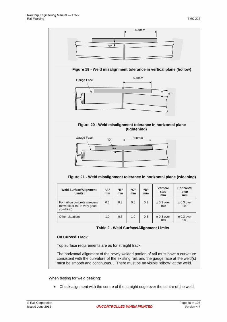
C4-14.3 Luting of moulds Use only the correct luting material for the process.
C4-14.4 Welding Biscuit Place the biscuit on top of the luted moulds, with the bottom of the biscuit clear of, but as close as possible to the outside edge of, one of the riser holes.
C4-15 The Crucible
C4-15.1 Examine the crucible Examine the new crucible for transport damage
C4-15.2 Loading the portion Load the portion into the crucible.
1. Double check that it is the correct portion i.e. correct process, correct rail size and hardness.
2. Make sure that the portion bag is sealed properly.
3. If the portion bag is split or not sealed then don't use it.
Some of the portion being lost, or moisture from the air may have got into the portion material which could cause a violent reaction and porosity (gas holes) in the weld.
4. If the portion material is free to move in the bag then turn it end on end a few times to mix the material which may have segregated during transport.
© Rail Corporation Page 28 of 103 Issued June 2012 UNCONTROLLED WHEN PRINTED Version 4.7

RailCorp Engineering Manual — Track Rail Welding TMC 222
5. Open the bag at one end and pour the material into the crucible.
6. Prepare a cone of powder in the centre of the crucible
7. Make sure that no portion is lost onto the ground or left in the bag and then put the bag aside for later reference for welding returns.
C4-15.3 Placing igniter nugget 1. Place the nugget igniter on top of the cone.
2. Gently press the igniter into the powder until the top of the igniter is level with the portion. (See Figure 5)
Figure 5 - Placement of Igniter
Keep the container of igniter nuggets close at hand in case another is needed when attempting to light the portion after the preheat.
3. Place the cover on the crucible.
C4-15.4 Attaching support units Depending on the welding process used, fit supports for the preheating torch and the welding crucible to attach them to the rail. Fit supports as required by the process specific practices detailed in Appendix 4.2 and Appendix 4.3.
C4-16 Preheating
C4-16.1 Preheating flame 1. Use the gas pressures specified for the welding process in Appendix 4.2 and
Appendix 4.3.
2. Use a dual stage oxy regulator to maintain an accurate flow rate during preheating.
© Rail Corporation Page 29 of 103 Issued June 2012 UNCONTROLLED WHEN PRINTED Version 4.7

RailCorp Engineering Manual — Track Rail Welding TMC 222
3. Use 10 mm inside diameter hoses.
4. DO NOT use excessively long hoses. In general no problems will be experienced with hoses up to 20 metres in length.
5. Maintain equipment in good repair (e.g. preheater clean, hand piece no leaks, regulators correct etc.).
C4-16.2 Preheater height 1. Check and adjust the preheater height to the correct height for the process,
before fitting the moulds (See Appendix 4.2 and Appendix 4.3).
C4-16.3 Lighting the preheater 1. Light the preheater using a flint gun and with a small amount of LPG.
2. Introduce oxygen flow.
3. Adjust the flame to suit the welding process being used (See Appendix 4.2 and Appendix 4.3).
C4-16.4 Preheating time Preheat for the recommended times (See Appendix 4.2 and Appendix 4.3).
Use a watch or a timer to check the preheat time.
C4-16.5 During the preheat 1. After the preheater is correctly adjusted take a look down the risers to see if
there are any large pieces of luting etc.
2. Remove any large pieces of luting etc by breaking them up carefully with wire so they will be blown out.
3. Keep a careful watch over the rail ends during the preheat period to ensure it is proceeding evenly.
4. If the heat is uneven adjust the direction of the preheater and the flame.
C4-17 The Weld
C4-17.1 Lighting the portion
Important Before lighting the portion, check the immediate area and remove any flammable material, taking note of wind direction and strength.
1. Remove the preheater when the preheat is complete.
© Rail Corporation Page 30 of 103 Issued June 2012 UNCONTROLLED WHEN PRINTED Version 4.7

RailCorp Engineering Manual — Track Rail Welding TMC 222
2. Place the welding biscuit in the centre of the mould using tongs (the biscuit is hot).
3. Place the crucible on the top of the mould.
4. Lift the crucible cover, and light the igniter nugget with the preheat torch on a reduced flame. When the portion lights, replace the cover.
5. Move back away from the reaction
6. If the portion fails to light, then it will generally be necessary to supply additional preheating to the moulds.
Figure 6 – Portion reaction
C4-17.2 Pouring the weld After the reaction is complete (within the range 18-28 seconds from when the portion was lit) and after portion has settled (a further 5-15 seconds), the thimble should tap cleanly and allow the weld metal to pour from the crucible over the biscuit into the mould.
1. Monitor the Reaction and Settlement time from lighting the portion to pouring of the weld and whether the reaction was complete when the thimble tapped.
If any weld portion does not tap, DO NOT move the crucible for at least 10 minutes.
If the weld portion taps after the correct settlement time, PLATE the weld and MONITOR for signs of failure.
If it appears the thimble tapped early or late or the reaction was too long, then the weld may not be to the appropriate standard.
© Rail Corporation Page 31 of 103 Issued June 2012 UNCONTROLLED WHEN PRINTED Version 4.7

RailCorp Engineering Manual — Track Rail Welding TMC 222
If the weld appears defective, replace the weld and report the failure to local field management for follow up investigation of the cause.
If the weld does not appear defective, plate the weld and report the situation to local field management so that early ultrasonic testing can be arranged.
Figure 7 - Pouring the weld
2. When the weld metal has poured from the crucible, set the timer to the cut off time for the weld.
3. Remove the crucible carefully from the mould covers.
4. Place the crucible in the established Hot Work Area.
C4-18 Break down and cut off of weld 1. Remove the slag trays three (3) minutes after the pour.
2. Remove the mould protectors and rail clamp approximately half a minute (30 seconds) before the due cut off time.
© Rail Corporation Page 32 of 103 Issued June 2012 UNCONTROLLED WHEN PRINTED Version 4.7

RailCorp Engineering Manual — Track Rail Welding TMC 222
Figure 8 - Removing the slag tray
Figure 9 - Removing the protectors
C4-18.1 Removing sand mould 1. Break the top of the moulds off onto the shovel when the timer indicates that the
cut off time is up.
2. If the weld metal is still liquid when the mould is broken off, replace the mould for a short period of time, say 15 to 20 seconds before trying again. This will very likely be the case if an extra long preheat was required to get the correct colour.
3. Place the top of the moulds in the hot waste crate.
© Rail Corporation Page 33 of 103 Issued June 2012 UNCONTROLLED WHEN PRINTED Version 4.7

RailCorp Engineering Manual — Track Rail Welding TMC 222
Figure 10 - Removing the sand mould
4. After removing the top of the mould, remove the luting paste and mould to the outer edge of the weld on both sides by sliding a hotset along the head of the rail.
5. Clean the rail head using a wire brush.
6. Completely remove the remainder of the sand mould, if necessary, using the hot set by hitting the hot set lightly with the hammer on the side of the excess metal head to get under it and then lift it away.
C4-19 Cutting off the excess head metal 1. Remove excess metal and trim the weld using Mechanical Weld Shears or Hot
sets. Weld shears are recommended because they are easier to operate and because they produce a better result.
2. Ensure that the excess metal has cooled sufficiently before attempting to remove it. If a bubbling effect or any globules of molten metal can be seen then it is necessary to wait for a short time until the surface goes a blotchy red.
C4-19.1 Using weld shears 1. Use the manufacturer’s recommended procedure for operating the weld shears.
2. Adjust hold down support to a 2.5mm gap under the head of a straight rail for standard welds, and a 3.5mm gap for wide gap welds.
© Rail Corporation Page 34 of 103 Issued June 2012 UNCONTROLLED WHEN PRINTED Version 4.7

RailCorp Engineering Manual — Track Rail Welding TMC 222
Figure 11 – Using Weld Shears
Figure 12 – Sheared Weld
C4-19.2 Using hot sets Use two hot sets cooling each in turn in a bucket of water that is in easy reach of the welder.
1. Lay the side of the cutting head of the first hot set flat on the head of the rail.
2. Strike the hot set with the hammer, gently at first, until it is certain that the metal has cooled sufficiently (if the metal is crumbly it is still too hot), and then with more force.
3. Keep the hot set blade square to the rail head so that the excess is cut off evenly.
4. Keep the hot set blade low enough to prevent "undercutting" of the weld i.e. cutting too deep.
5. tilt the back of the hot set up a little when the excess is cut about half way through, or if the cut starts to rise too much above level with the rail head.
6. Place the excess metal in the Hot Work Crate.
© Rail Corporation Page 35 of 103 Issued June 2012 UNCONTROLLED WHEN PRINTED Version 4.7

RailCorp Engineering Manual — Track Rail Welding TMC 222
7. Change hot sets, putting the first into the water.
8. Cut the gauge side riser as follows:
o Cut the corner from the running surface to the gauge face (approximately 45°).
o Cut vertically down the gauge face. If the cut is tending to leave too much metal then tilt the hot set away from the rail but be careful not to "undercut".
9. Change hot sets again.
10. Cut the outside riser in the same manner.
11. Cut any sharp corners where the gauge face meets the running surface, if required.
Figure 13 - Cutting off Sides of Rail
12. Bend the top of the risers away from the weld as much as possible (about 450) using the back of the hot set.
13. Leave them connected until the weld is cool.
14. Remove them when cold, by tapping them back toward the web.
C4-20 Disturbing the weld 1. DO NOT carry out any rail pulling, vibration or other work which may disturb the
weld for 10 minutes after the excess head metal has been removed.
2. If the rail gap is being held by rail tensors during the weld, DO NOT remove the tensors until 20 minutes after the excess head metal has been removed.
If there is any indication that the rail may have moved during this time, the weld MUST be replaced. If it cannot be replaced immediately, it MUST be plated and reported immediately to the local field management for follow up.
© Rail Corporation Page 36 of 103 Issued June 2012 UNCONTROLLED WHEN PRINTED Version 4.7

RailCorp Engineering Manual — Track Rail Welding TMC 222
C4-20.1 Rough grinding DO NOT allow trains to pass over the weld until at least 10 minutes after the removal of the excess weld metal.
Rough grind the weld down to approximately 1mm above the rail head using the rail profile grinder.
DO NOT grind closer since on cool down the weld could finish up out of tolerance.
Figure 14 – Weld after rough grinding
C4-20.2 Preparation before allowing a train across the weld. Before allowing a train across the weld carry out the following steps:
1. Remove the wedges from one side of the weld
2. Reinstall any pads that have been removed. DO NOT overlift the rail. You may need to cut the lip off one side of the pad so that you can slide the pad in. If you cut off the sides of the pad make sure that the cut-off end of the pad is placed in the direction of travel so that any movement is restricted (See Figure 15).
Cut off these lugs
Direction of travel
Figure 15 - Replacing pads
3. Pack sleepers as required. You MUST mechanically pack welds on concrete sleepered track
4. Remove the wedges from the other side of the weld
5. Reinstall any pads that have been removed.
© Rail Corporation Page 37 of 103 Issued June 2012 UNCONTROLLED WHEN PRINTED Version 4.7

RailCorp Engineering Manual — Track Rail Welding TMC 222
6. Pack sleepers up to the rail as required and re-install fastenings. You MUST mechanically pack welds on concrete sleepered track.
If possible leave them until the weld has cooled. In this case tap the wedges back in under the rail foot after cut off.
C4-20.3 Speed across a new weld Apply the following speed restrictions over a weld until it is Finish Ground.
Weld finish Speed (kph)
Hot Set 15
Weld shears 25
Rough Ground 25
C4-21 Finishing off the weld 1. DO NOT "Finish Grind" the weld until at least 1 hour after removal of the excess
head metal. This may lead to discoloration (blueing). It is not correct practice and must be noted in the "Comments" field in SmartWeld for follow up.
2. Welds MUST be allowed to cool naturally in air. DO NOT under any circumstances accelerate the cooling by applying water. This changes the metallurgy of the weld and may lead to failure
3. Finish grind the weld to tolerance using the rail profile grinder. The tolerances are detailed below.
4. Grind the rail for a distance 300mm each side of the weld using the rail profile grinder.
Figure 16 – Grinding
5. Check the work frequently while grinding using a straightedge to make sure that a good straight surface, with no hollows, is produced.
© Rail Corporation Page 38 of 103 Issued June 2012 UNCONTROLLED WHEN PRINTED Version 4.7

RailCorp Engineering Manual — Track Rail Welding TMC 222
6. DO NOT to over-grind as a dipped weld can only be repaired by replacing the weld.
7. Grind the gauge face, running surface and field side of the rail head flush.
8. Grind the transition from running surface to gauge face to a smooth curve.
9. Grind the outside of the rail head smooth.
Use a hand grinder ONLY in an absolute emergency.
If a hand grinder must be used, take extra care to ensure a smooth surface without hollows. Re-grind the weld using a profile grinder within 24 hours.
Figure 17 – Finished Weld (Note Weld Identification label
C4-22 Weld Alignment Acceptance Limits The following requirement is extracted from RailCorp standard ESC 220
Straightness
Welds shall be vertical to the top surface of the rail with no more than 5mm mismatch between the top and bottom of the weld
On Straight Track
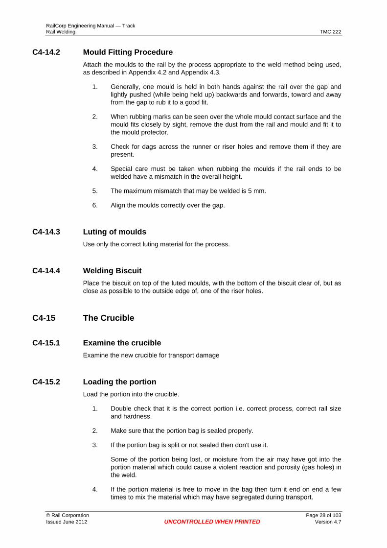
Check the top surface and rail alignment with a 1m straight edge as illustrated in Figure 18 and Figure 19 (top surface) and Figure 20 and Figure 21 (alignment).
The permitted tolerances are as shown in Table 2.
Figure 18 - Weld misalignment tolerance in vertical plane (peaking)
500mm
“A”
© Rail Corporation Page 39 of 103 Issued June 2012 UNCONTROLLED WHEN PRINTED Version 4.7
RailCorp Engineering Manual — Track Rail Welding TMC 222
500mm
“B”
Figure 19 - Weld misalignment tolerance in vertical plane (hollow)
500mmGauge Face
“C”
Figure 20 - Weld misalignment tolerance in horizontal plane (tightening)
Gauge Face 500mm“D”
Figure 21 - Weld misalignment tolerance in horizontal plane (widening)
Weld Surface/Alignment Limits
“A” mm
“B” mm
“C” mm
“D” mm
Vertical step mm
Horizontal step mm
For rail on concrete sleepers (new rail or rail in very good condition)
0.6 0.3 0.6 0.3 ± 0.3 over 100
± 0.3 over 100
Other situations 1.0 0.5 1.0 0.5 ± 0.3 over 100
± 0.3 over 100
Table 2 - Weld Surface/Alignment Limits
On Curved Track
Top surface requirements are as for straight track.
The horizontal alignment of the newly welded portion of rail must have a curvature consistent with the curvature of the existing rail, and the gauge face at the weld(s) must be smooth and continuous. . There must be no visible “elbow” at the weld.
When testing for weld peaking:
• Check alignment with the centre of the straight edge over the centre of the weld.
© Rail Corporation Page 40 of 103 Issued June 2012 UNCONTROLLED WHEN PRINTED Version 4.7

RailCorp Engineering Manual — Track Rail Welding TMC 222
• Move the straight edge so that one end is at the centre of weld and check alignment again.
• Move the straight edge so that the other end is at the centre of weld and check alignment again.
This additional check is essential to check that grinding of the weld has not transferred the peak error away from the centre of the weld.
There are two different types of peak that do not comply with the defect limits.
1. An excessive peak resulting from the rails being peaked too much, prior to welding. Attempts to remove this type of problem with a long grind do not result in the removal of the peak but in a transfer of the peak to another location away from the weld (See Figure 22). Classify this as a peak even though the peak is not in the weld. This can only be repaired with a closure.
Peaked weld
Weld ground to remove peak
Peak transferred to end of grinding
Figure 22 – Transfer of peaked weld by grinding
2. A peak resulting from insufficient removal of the weld metal. It can sometimes be the case that the weld is ground to profile on the gauge side but is left proud on the field side top of the rail head. This non-compliance will not correct itself no matter how long the weld is left in the track and means that the weld cannot be tested on the field side top and will be failed as a peak weld. This kind of peak is easily removed with further grinding.
There are four different types of dip that do not comply with the defect limits.
1. A dip resulting from the rails not being peaked enough prior to welding. This can only be repaired by a replacement weld or a rail bending process.
2. A dip resulting from the rails not being peaked enough prior to welding but the weld metal has been left high to try and compensate. This is the most harmful alignment problem as the wheels hit this very hard. This also can only be repaired by a replacement weld or a rail bending process combined with grinding.
3. A dip resulting from a dip in the track. Packing may resolve this problem but a ‘memory’ is often set up in the weld that can only be repaired with a closure or rail bending.
4. A dip resulting from an attempt to weld a crippled rail joint. This can only be reliably repaired with a closure.
© Rail Corporation Page 41 of 103 Issued June 2012 UNCONTROLLED WHEN PRINTED Version 4.7

RailCorp Engineering Manual — Track Rail Welding TMC 222
Dips cannot be removed with a long grind. This will only transfer the misalignment to another location away from the weld. This can only be repaired with a closure.
C4-23 Visual inspection of welds 1. Clean and visually inspect each weld after the weld has been completed prior to
leaving the worksite.
2. Remove all mould material to allow visual inspection and later ultrasonic testing.
3. Remove any welds that show holes, slag inclusions, hot tears or other defects.
C4-24 Identifying aluminothermic welds All welds need to be identified to allow testing and tracking of material and welder performance.
1. When a weld has been completed place a weld identification label (see Figure 23on the inside foot of the rail 300mm - 400mm from the weld.
WELD No. 037901
Figure 23 - Weld Identification Label (Sample) Shown actual size (80mm x 35mm)
2. Paint ALL aluminothermic welds after grinding using a fluorescent pink line marking paint. DO NOT paint over the Weld Identification Label.
Apply the paint from field side of the rail head down the web on both sides of the rail for at least 100mm either side of the weld (See Figure 24). DO NOT paint the running surface and the foot of the rail. Any paint that gets onto the rail foot should be wiped off with a rag before it dries.
When the weld has been ultrasonically tested the rail flaw detection operator will paint over the pink paint mark with blue paint if satisfactory and yellow paint if a defect is found.
© Rail Corporation Page 42 of 103 Issued June 2012 UNCONTROLLED WHEN PRINTED Version 4.7

RailCorp Engineering Manual — Track Rail Welding TMC 222
Figure 24 – New weld paint marking
C4-25 Before leaving the site 1. Box up the sleepers, check all fastenings are replaced.
2. Make a careful check for any fires or smouldering sleepers, bridge timbers or vegetation and extinguish any fires found.
3. Replace any burnt insulating pads on concrete sleepers.
4. Clean up and remove from site any rubbish including the steel scrap.
C4-26 Recording aluminothermic welds 1. Each field welder is required to complete a Welding Return for all field welds
installed in the track. It is your responsibility to ensure that the return is completed.
2. Record the information about each weld in SmartWeld (or on the Welding Return Form WR1 if the SmartWeld system is not available (Appendix 4.1). The fields on the form are explained in Table 3.
3. An alternative Welding Return Form WR2, which has space for multiple entries, is available for use if preferred. The fields on the form are explained in Table 3. Welding information is still required to be entered into SmartWeld.
Codes have been supplied for Weld Reason, Weld type and Site conditions (See Table 4).
© Rail Corporation Page 43 of 103 Issued June 2012 UNCONTROLLED WHEN PRINTED Version 4.7

RailCorp Engineering Manual — Track Rail Welding TMC 222
Welder’s Details
Welder's Name Name of welder If the welder is a contractor, Insert Welding company name as well.
Welder's Licence No.
Welder's signature (Not required in SmartWeld)
Weld Details
Weld Date Insert date of completion of the weld.
Base Code & Line Insert sector code (sector or base) from code listing
Track Circle track identifier UP or DOWN
District Insert District (Illawarra, Central, West, North or Infrastructure Facilities)
Km Km of weld NOTE: Only ONE weld can be recorded in each section of the return, therefore a closure rail or a Glued Insulated Joint would require two (2) kilometrages, e.g. 93.400 and 93.403
Rail Circle to indicate the rail welded UP = Up rail and DN = Down rail UT = Up turnout Rail, DT = Down Turnout Rail
Weld Number Weld number from weld identification label
Rail Size Rail size e.g. 60HH, 60, 53, 47 Include both rail sizes if it is a junction weld
Weld Reason Insert code from list (see Table 4)
Weld Type Weld process code from list (see Table 4)
Weld Condition Insert appropriate code from list (see Table 4)
Weather Condition Insert appropriate code from list (see Table 4)
Track Condition Insert appropriate code from list (see Table 4)
Batch Number Batch number from the weld portion bag
Have rail tensors been used?
Circle YES or NO Must be completed for all Adjustment welds and welds when RAIL OUT/RAIL IN process is used
Punch marks before Insert length between punch marks before rail is cut
Punch marks after Insert length between punch marks after rail is welded
Adjustment maintained Are the before and after measurements of punch marks the same (within ± 3mm)? Circle YES or NO
Rail temperature Temperature of rail at time of weld
Have welds been packed?
If the response is NO then additional details are required
Are closures less than 6m in length crowed to correct curvature?
Have closures crowed to give smooth alignment in curves? If the response is NO additional details are required.
Comments Write down any comments relevant to the work
Table 3 - Information to be recorded on Welding Return
© Rail Corporation Page 44 of 103 Issued June 2012 UNCONTROLLED WHEN PRINTED Version 4.7

RailCorp Engineering Manual — Track Rail Welding TMC 222
Welding codes Description Code
Weld Reason (code) GIJ 1 Broken rail / weld (also insert Railfail No.) 2 Switch 3 Stockrail 4 Closure 5 Adjustment (CWR) 6 Adjustment (LWR) 12 Free weld (only when welding shorter lengths in preparation for CWR) 7 Rerailing - Change from one rail size to another e.g. 53 to 60 8 Ground out tolerance 9 Broken crossing 10 Rail defect (also insert Railfail No.) 11 Other Only use if absolutely necessary 20
Weld Type SKVF Standard
DO NOT USE FOR NEW WELDS THERMIT
1 SKVF Head repair 2 SKVF Junction 3 SKVF Wide Gap 4 SKVE Standard 15 PLK CJ (one shot)
RAILTECH 11
PLK CJ Wide Gap 13 PLK CJ Junction 14 Flashbutt 20
Site Conditions / Code Weld Thimble tap too early 1 Weld blowout 2 No problems 3 Other Only use if absolutely necessary 10 Weather Sunny / hot 1 Sunny / cold 2 Intermittent showers 3 Rain 4 Cloudy 5 Night 6 Other Only use if absolutely necessary 10 Track Good condition 1 Track pumping 2 Poor top 3 Poor alignment 4 Bog hole 5 High rail wear 6 Mismatch rail profiles 7 Track panels under construction (off track) 8 Other Only use if absolutely necessary 10
Table 4 - Welding Codes
© Rail Corporation Page 45 of 103 Issued June 2012 UNCONTROLLED WHEN PRINTED Version 4.7

RailCorp Engineering Manual — Track Rail Welding TMC 222
C4-27 Reporting aluminothermic welds Each field welder is required to complete a Weld Return for all field welds installed in the track. It is your responsibility to ensure that the weld return data is uploaded (or entered, if manual forms are used) into the web database within two (2) days.
C4-28 Welding on slab track The following acceptance limits are extracted from RailCorp standard ESC 220
Aluminothermic welds shall not sit directly on slab track.
The method applied for welding rail on slab track depends on the height of the rail above the slab.
If rail has been installed on cologne egg fastenings, there is sufficient gap between the slab and the underside of the rail to use either Thermit or Railtech processes, but the recommended process is the Railtech PLK-CJ weld because it requires less height (footless weld).
If rail has been installed on other fastenings and there is insufficient room to install the moulds, use the following process:
1. Unclip approximately 7m each side of the proposed weld.
2. Lift the rail onto blocks (100mm x100mm).
3. Lift the rail onto ¼ sleeper either side of the weld.
4. Align the rail using dog/pin holes in the ¼ sleeper.
5. Install the weld using the standard procedure.
If possible aluminothermic welds on the slab should be avoided. If, however, they cannot be avoided, the normal practise is to remove a small amount of concrete from the surface of the slab to allow the weld to sit free, including when under load.
© Rail Corporation Page 46 of 103 Issued June 2012 UNCONTROLLED WHEN PRINTED Version 4.7

RailCorp Engineering Manual — Track Rail Welding TMC 222
Appendix 4.1 Welding Return
Welder’s Details Welder’s Name Licence No. Signature
Weld Date Base Code /Track D M Y BASE CODE LINE TRACK
District Km Rail UP DN UT DT
Weld Details UP DN
Test Date
Alignment Failure IDRail Fail ID
Punch Mark Check
Weld Testing Data
D M Y
Ultrasonic Pass mm
Alignment Pass D M Y
Alignment Failure IDYES NO
YES NO Alignment Pass YES NO
Comments
RFD Operator’s Name Signature
Retest (Alignment Test Date
RFD Operator’s Name Signature
Weld Date Base Code /Track D M Y BASE CODE LINE TRACK
District Km Rail
Weld Details UP DN
Test Date
Alignment Failure IDRail Fail ID
Punch Mark Check
Weld Testing Data
D M Y
Ultrasonic Pass mm
Alignment Pass D M Y
Alignment Failure IDYES NO
YES NO Alignment Pass YES NO
Comments
RFD Operator’s Name Signature
Retest (Alignment Test Date
RFD Operator’s Name Signature
Weld Return Form WR1
UP DN UT DT
Weld Condition Weather Condition
60HH 60 53 47 Other ___ Weld Number Rail Size Weld Reason Weld Type
Punch Mark Before
Punch Mark After
Adjustment Maintained
mm mm
Rail Temperature 0C
Track Condition Batch Number
YES NOHas weld been packed?
YES NO
YES NO
Comments
Are closures less than 6m in length crowed to correct curvature?
Have rail tensors been used? YES NO
© Rail Corporation Page 47 of 103 Issued June 2012 UNCONTROLLED WHEN PRINTED Version 4.7

RailCorp Engineering Manual — Track Rail Welding TMC 222
Welding Return Form WR2
Welder's Name Welder's Signature Date Ultrasonic Operator Licence No. Welder’s Home Station Name Week Ending Supervisor's Signature Date Signature
WELDER TO COMPLETE RAIL FLAW DETECTION OFFICER TO COMPLETE
Weld Location Weld Detail Ultrasonic and Alignment Test
Steel in-Steel out Alignment Retest Site Conditions /Codes Punch Marks
Line
No.
Dat
e
Sec
tor C
ode
Track Km R
ail (
U/D
)
Rai
l Siz
e
Wel
d R
easo
n(C
ode)
Bat
ch N
o.
Wel
d S
ticke
rN
o.
Wel
d Ty
pe(C
ode)
Wel
d
Wea
ther
Trac
k
Bef
ore
Afte
r
Rai
l Tem
p 0 C
Tensors YES or
NO
Date
OK YES or
NO
Rail Fail No. OR
Alignment Failure No. D
efec
t Typ
eR
ail o
rA
lignm
ent
Punc
h M
ark
Che
ck
Date Alignment
Pass YES or NO
1
2
3
4
5
6
7
8
9
NOTES Associated Work Have welds been packed? YES NO
Are closures less than 6m in length crowed to correct curvature? YES NO
Do rail ends and closures match existing rail? YES NO
© Rail Corporation Page 48 of 103 Issued June 2012 UNCONTROLLED WHEN PRINTED Version 4.7

RailCorp Engineering Manual — Track Rail Welding TMC 222
Appendix 4.2 Thermit Welding Methods These Special Instructions apply to Thermit’s SKVE Process
A-4.2-1 Thermit SKVE method These instructions are in addition to the General Instructions in Chapter 4.
A-4.2-1.1 Gap The weld gap for all SKVE welds except wide gap is 28 mm ±2.
A-4.2-1.2 Attaching the universal clamp 1. Position the universal clamp on the rail by using the gap gauge and check that
the locating arm is in line with the centre of the gap (see Figure 26).
Figure 25 – Universal clamp
2. Check that the universal clamp is vertical after tightening to the rail.
© Rail Corporation Page 49 of 103 Issued June 2012 UNCONTROLLED WHEN PRINTED Version 4.7

RailCorp Engineering Manual — Track Rail Welding TMC 222
Figure 26 - Positioning of the Universal clamp with the aid of the Gap Gauge
3. Assemble the preheating torch and fit it into the supporting cradle.
A-4.2-1.3 Setting preheater height 1. Place the preheater in the preheater support on the universal clamp.
2. Check that the height is 40 mm between the top of the rail and the bottom of the preheater tip. (See Figure 27)
Figure 27 - Adjusting Preheater Torch Height
3. Remove the preheating torch from its cradle.
A-4.2-1.4 Check moulds and rubbing in (See Section C4-14.2) 1. Check the moulds for cracks in the foot/web area in addition to the usual
checks.
2. Take care when rubbing in the moulds, ensuring that the foot/web is not cracked.
© Rail Corporation Page 50 of 103 Issued June 2012 UNCONTROLLED WHEN PRINTED Version 4.7

RailCorp Engineering Manual — Track Rail Welding TMC 222
Figure 28 – Rubbing in Moulds
A-4.2-1.5 Attaching moulds to rail and luting 1. Place each side in mould covers
2. Place the mould centrally over the rail gap and use the locating arms of the universal clamp to hold the moulds in place by tightening the ”T” screw to apply a firm but not excessive pressure to the mould.
Figure 29 - Positioning the Moulds
3. Pack luting paste around the moulds.
4. Place the slag tray on the mould clamp and place dry luting sand in the tray
© Rail Corporation Page 51 of 103 Issued June 2012 UNCONTROLLED WHEN PRINTED Version 4.7
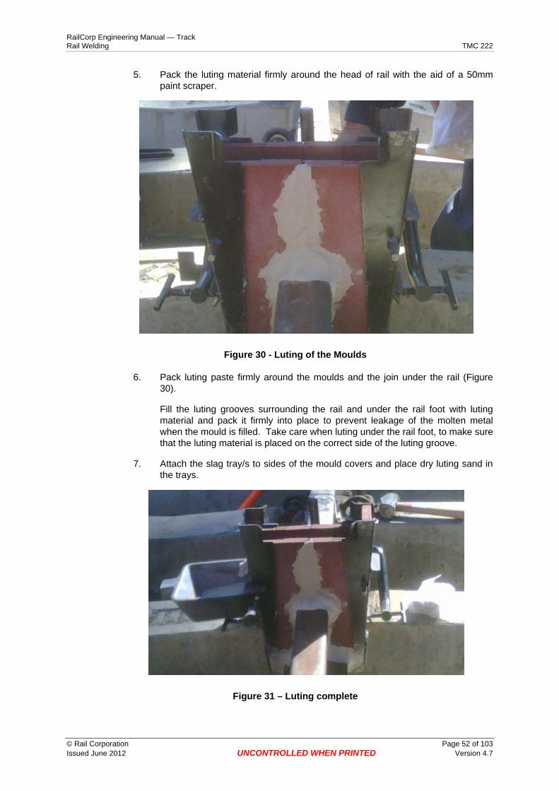
RailCorp Engineering Manual — Track Rail Welding TMC 222
5. Pack the luting material firmly around the head of rail with the aid of a 50mm paint scraper.
Figure 30 - Luting of the Moulds
6. Pack luting paste firmly around the moulds and the join under the rail (Figure 30).
Fill the luting grooves surrounding the rail and under the rail foot with luting material and pack it firmly into place to prevent leakage of the molten metal when the mould is filled. Take care when luting under the rail foot, to make sure that the luting material is placed on the correct side of the luting groove.
7. Attach the slag tray/s to sides of the mould covers and place dry luting sand in the trays.
Figure 31 – Luting complete
© Rail Corporation Page 52 of 103 Issued June 2012 UNCONTROLLED WHEN PRINTED Version 4.7

RailCorp Engineering Manual — Track Rail Welding TMC 222
Figure 32 –Preheating
A-4.2-1.6 Preheat Preheating Pressures
An Oxy check gauge is to be used at all times on the hand piece.
LPG 150 KPA
Oxygen 400 KPA
1. Preheat the rail ends to dull red web and foot with some colour change in the head.
This should be achieved after:
Rail size Standard and junction weld (mins)
47kg 3 53kg 3 60kg 3.5
A-4.2-1.7 Crucible The crucible is a single use product. No crucible pre heat is required
1. Check crucible for damage and that there is no loose crucible lining over the thimble.
2. Load portion
3. Insert ignition plug
© Rail Corporation Page 53 of 103 Issued June 2012 UNCONTROLLED WHEN PRINTED Version 4.7

RailCorp Engineering Manual — Track Rail Welding TMC 222
Figure 33 –Thermit SKVE Single Use crucible
A-4.2-1.8 Strip down and cut off
SKVE Standard and junction
(mins)
Strip down 5 Cut off 6
A-4.2-1.9 Quick Reference Table
STANDARD Weld JUNCTION Weld
Rail Size Kg. 47 53 60 41-47 47-53 53-60
Prealignment For Welding Gap with 1 m Straight Edge
Top (Running Surface) 1.5 to 1.8 mm Each End 1.5 to 1.8 mm Each End
Side (Guage Face) No Gap No Gap
Gap (mm) 28 ± 2 28 ± 2
Oxy Pressure (kPa) 400 400
LPG Pressures (kPa) 150 150
Preheat Time (min) 3 3 3.5 3 3 3.5
Colour Required red foot & web some change in head
red foot & web some change in head
Strip Down Time (mins) 5 5
Cut Off Time (mins) 6 6
Finish Grind Time 1 Hour 1 Hour
© Rail Corporation Page 54 of 103 Issued June 2012 UNCONTROLLED WHEN PRINTED Version 4.7

RailCorp Engineering Manual — Track Rail Welding TMC 222
A-4.2-2 Thermit Head Repair Weld (Welding Procedure for all rail sizes)
A-4.2-2.1 Preliminary 1. Examine the head defects, their size, number and proximity to each other and
determine if repair of the defects or replacement by a closure, is the most economical solution.
2. Arrange for the head defect to be ultrasonically tested to determine the depth of any defect. DO NOT use Thermit Head Repair Welds to repair defects that extend more than 8mm below the running surface.
A-4.2-2.2 Repair Procedure 1. Check track geometry over the repair area and lift and pack if required.
2. Locate the head defect to be repaired.
3. Measure the head defect to determine the number of welds required. The maximum repair area of one weld is 100mm. When using multiple repairs the head repair welds must overlap by at least 10mm.
4. Mark with chalk the 100mm repair area or the mould location to evenly cover the repair area.
5. If the repair area falls over a sleeper, lift the dogspikes or remove the clips on that sleeper alone, otherwise lift the dogs or remove the clips on the sleeper each side of the repair area.
6. Rub the moulds to a neat fit on the rail and to each other (the reservoir half on the high side), fitted to the mould protector then set aside.
7. Peak of the rail at the repair area to approx. 1.5mm each side of the 1metre straight edge using wedges on the sleeper/s under the repair area.
8. Fit the universal rail clamp to the rail, locating the arms at the centre of the repair area.
9. Check and adjust the preheater height to 70mm.
10. Apply a bead of luting from the tube to the luting grooves in the moulds.
11. Fit the moulds centrally over the repair area and clamp firmly.
12. Tear the 0.5mm cardboard and place half under each end of the mould-luting wedge.
13. Pack the wedge firmly with luting sand or premixed paste.
14. Fit the biscuit to the moulds ensuring it locates properly.
15. Place the crucible on the clamp and adjust the height to 20mm above the moulds with the pouring throat directly above the wire loop on the biscuit.
© Rail Corporation Page 55 of 103 Issued June 2012 UNCONTROLLED WHEN PRINTED Version 4.7
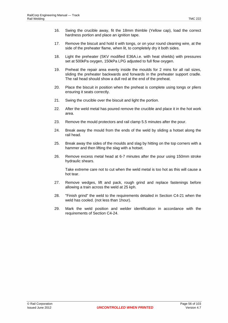
RailCorp Engineering Manual — Track Rail Welding TMC 222
16. Swing the crucible away, fit the 18mm thimble (Yellow cap), load the correct hardness portion and place an ignition tape.
17. Remove the biscuit and hold it with tongs, or on your round cleaning wire, at the side of the preheater flame, when lit, to completely dry it both sides.
18. Light the preheater (SKV modified E36A.i.e. with heat shields) with pressures set at 500kPa oxygen, 150kPa LPG adjusted to full flow oxygen.
19. Preheat the repair area evenly inside the moulds for 2 mins for all rail sizes, sliding the preheater backwards and forwards in the preheater support cradle. The rail head should show a dull red at the end of the preheat.
20. Place the biscuit in position when the preheat is complete using tongs or pliers ensuring it seats correctly.
21. Swing the crucible over the biscuit and light the portion.
22. After the weld metal has poured remove the crucible and place it in the hot work area.
23. Remove the mould protectors and rail clamp 5.5 minutes after the pour.
24. Break away the mould from the ends of the weld by sliding a hotset along the rail head.
25. Break away the sides of the moulds and slag by hitting on the top corners with a hammer and then lifting the slag with a hotset.
26. Remove excess metal head at 6-7 minutes after the pour using 150mm stroke hydraulic shears.
Take extreme care not to cut when the weld metal is too hot as this will cause a hot tear.
27. Remove wedges, lift and pack, rough grind and replace fastenings before allowing a train across the weld at 25 kph.
28. "Finish grind" the weld to the requirements detailed in Section C4-21 when the weld has cooled. (not less than 1hour).
29. Mark the weld position and welder identification in accordance with the requirements of Section C4-24.
© Rail Corporation Page 56 of 103 Issued June 2012 UNCONTROLLED WHEN PRINTED Version 4.7

RailCorp Engineering Manual — Track Rail Welding TMC 222
Appendix 4.3 Railtech Welding Methods These Special Instructions apply to Railtech’s PLKCJ welds.
A-4.3-1 Railtech PLKCJ These instructions are in additional to the General Instruction in Chapter 4.
A-4.3-1.1 Gap
Weld type Gap Rail size
PLKCJ 25 mm ± 2 53 & 60
A-4.3-1.2 Setting the Regulator pressures 1. Assemble the oxy/LPG equipment with a LP test gauge at the hand piece.
2. Turn on cylinders (ensure that the control knob is fully out).
3. Open the handle oxygen valve, turn control knob in until the regulator is reading 300kPa then close handle valve.
4. Open the handle LPG valve, turn control knob in until the test gauge is reading 40kPa then close handle valve.
A-4.3-1.3 Final adjustment 1. Light the torch, turn LPG handle valve fully on.
2. Adjust oxy handle valve to required flame.
3. Check and adjust LPG so that the test gauge reads 40kPa.
A-4.3-1.4 Attaching moulds to rail and luting 1. Place each side of the mould in the mould covers and place base plate mould in
the base plate cover.
2. Place luting paste from the tube supplied on each side of base plate.
© Rail Corporation Page 57 of 103 Issued June 2012 UNCONTROLLED WHEN PRINTED Version 4.7

RailCorp Engineering Manual — Track Rail Welding TMC 222
Figure 34 - Base plate mould and luting in base plate
3. Place base plate under the foot of the rail centrally covering the weld gap and tighten clamp screws while tapping base plate.
Figure 35 –Base plate clamped to rail
4. Place side mould on rail and ensure that the moulds are aligned to the base plate.
5. Fit mould clamp and tighten.
© Rail Corporation Page 58 of 103 Issued June 2012 UNCONTROLLED WHEN PRINTED Version 4.7
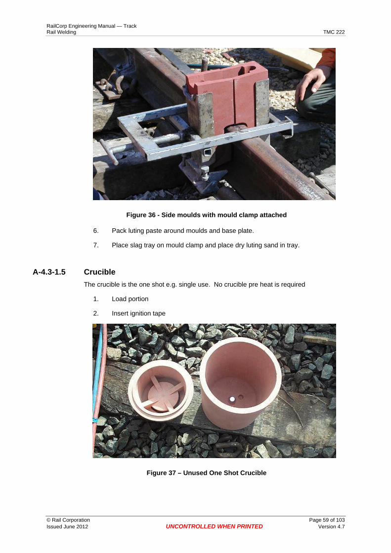
RailCorp Engineering Manual — Track Rail Welding TMC 222
Figure 36 - Side moulds with mould clamp attached
6. Pack luting paste around moulds and base plate.
7. Place slag tray on mould clamp and place dry luting sand in tray.
A-4.3-1.5 Crucible The crucible is the one shot e.g. single use. No crucible pre heat is required
1. Load portion
2. Insert ignition tape
Figure 37 – Unused One Shot Crucible
© Rail Corporation Page 59 of 103 Issued June 2012 UNCONTROLLED WHEN PRINTED Version 4.7

RailCorp Engineering Manual — Track Rail Welding TMC 222
A-4.3-1.6 Preheater support 1. Attach the preheater support to the opposite rail and fit the pre heater over the
support.
A-4.3-1.7 Preheater tip PLKCJ weld preheater tip.
A-4.3-1.8 Preheater height The preheater height for PLKCJ is the low setting on the support.
A-4.3-1.9 Preheating pressures
Weld Type LPG (Kpa)
Oxygen (Kpa)
PLKCJ 40 300
A-4.3-1.10 Preheat 1. Preheat the rail ends to dull red web and foot and some colour change in the
head.
This should be achieved at
Rail size Preheat time (mins) PLKCJ
53kg 3 60kg 4
A-4.3-1.11 Placement and lighting of crucible 1. After preheating the rail ends and placement of the biscuit in the moulds, place
the crucible in the centre on top of the moulds.
2. Remove the crucible lid, light the portion and replace the lid.
A-4.3-1.12 Removal of crucible 1. Use a crucible handling tool to remove the crucible from the moulds after the
required time and place it in waste bin. DO NOT use bare hands to handle used crucibles.
© Rail Corporation Page 60 of 103 Issued June 2012 UNCONTROLLED WHEN PRINTED Version 4.7
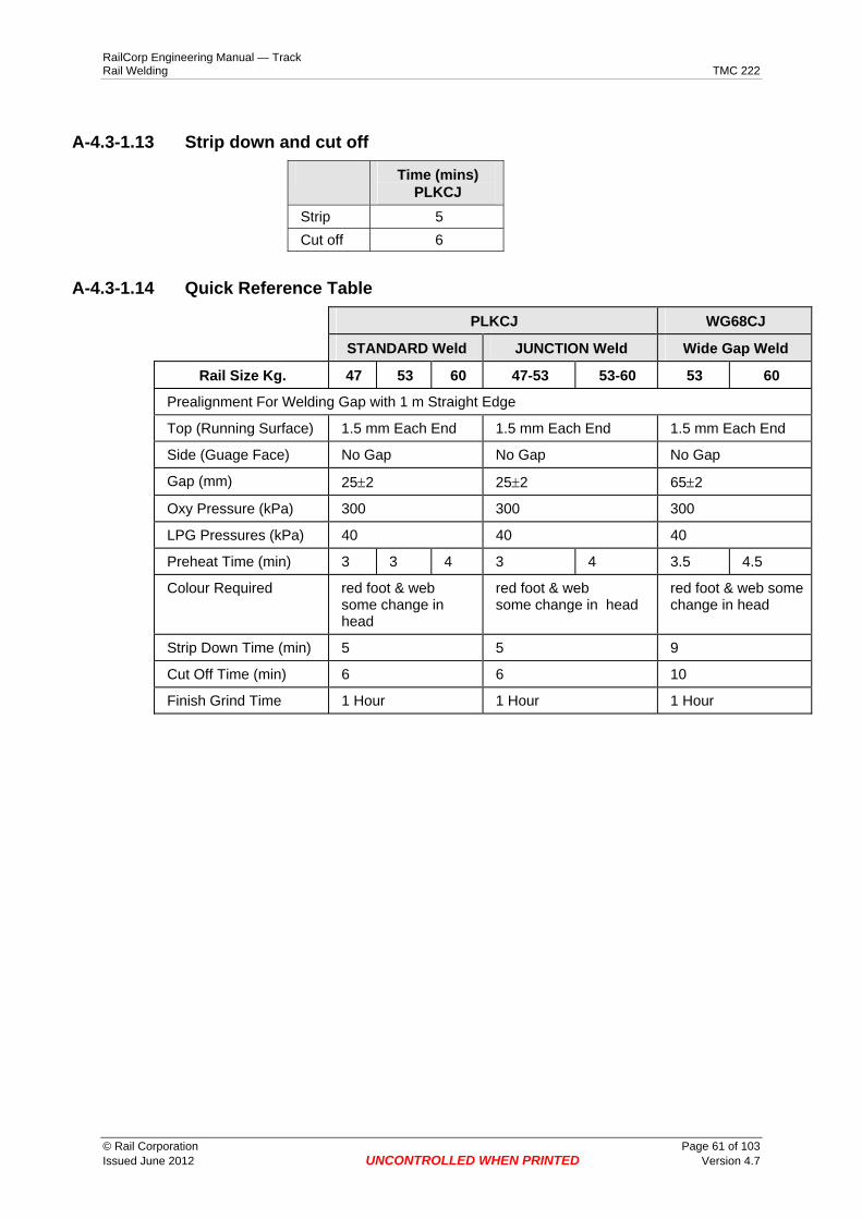
RailCorp Engineering Manual — Track Rail Welding TMC 222
A-4.3-1.13 Strip down and cut off
Time (mins) PLKCJ
Strip 5 Cut off 6
A-4.3-1.14 Quick Reference Table
PLKCJ WG68CJ
STANDARD Weld JUNCTION Weld Wide Gap Weld
Rail Size Kg. 47 53 60 47-53 53-60 53 60
Prealignment For Welding Gap with 1 m Straight Edge
Top (Running Surface) 1.5 mm Each End 1.5 mm Each End 1.5 mm Each End
Side (Guage Face) No Gap No Gap No Gap
Gap (mm) 25±2 25±2 65±2
Oxy Pressure (kPa) 300 300 300
LPG Pressures (kPa) 40 40 40
Preheat Time (min) 3 3 4 3 4 3.5 4.5
Colour Required red foot & web some change in head
red foot & web some change in head
red foot & web some change in head
Strip Down Time (min) 5 5 9
Cut Off Time (min) 6 6 10
Finish Grind Time 1 Hour 1 Hour 1 Hour
© Rail Corporation Page 61 of 103 Issued June 2012 UNCONTROLLED WHEN PRINTED Version 4.7

RailCorp Engineering Manual — Track Rail Welding TMC 222
Appendix 4.4 Hot Work Crate
Handles
500mm dia
13mm round
Lifting lugs 100 x 75 x 6mm
500m
m
25 x 25 x 2.2 rhs
100m
m
25 bar
x 6mm
Mesh “expamet” ref 3022
© Rail Corporation Page 62 of 103 Issued June 2012 UNCONTROLLED WHEN PRINTED Version 4.7

RailCorp Engineering Manual — Track Rail Welding TMC 222
Appendix 4.5 Care and Maintenance of Welding Equipment
A-4.5-1 General
A-4.5-1.1 Moisture Portions, crucible linings, crucible thimbles, moulds, and pouring pots should be kept dry at all times. Portions cannot be dried and used once they become damp. If they are used, the reaction will be violent and the weld weak and porous. The other materials may be used if heated and thoroughly dried before use.
A-4.5-1.2 Maintenance On a regular basis checks should be made of all equipment and the following work should be done:
Sharpening hot sets, inserting handles into hot sets or hammers; cleaning, lubricating, and filling the grinding machine; cleaning screw threads on equipment, checking crucibles and replacing if necessary and cleaning the preheating torch should be carried out.
A-4.5-2 Single use crucible As far as possible, the crucible must always be kept dry. Check for evidence of moisture damage (white powder coating on outside of crucible).
Care must be taken when handling crucibles because damage to the crucible will require its replacement.
A-4.5-3 Preheating torch
A-4.5-3.1 Care The preheating torch should be placed carefully in the tool box after use, before transportation. Torches must not be thrown on the ballast. After preheating and before tapping, take off the torch and lay it down with the burner head upwards. Care must be taken to make sure that the torch head does not come in contact with the mould, otherwise the torch head will become too hot and melt.
A-4.5-3.2 Maintenance Clogged or damaged torches not in good working order must not be used and must be repaired only by experienced workers.
After 100 welds have been made, the holes in the burner head should be cleaned out with the tools provided.
If this maintenance is not carried out, the performance of the torch will deteriorate resulting in longer preheating times or insufficient preheating of the rail ends.
© Rail Corporation Page 63 of 103 Issued June 2012 UNCONTROLLED WHEN PRINTED Version 4.7

RailCorp Engineering Manual — Track Rail Welding TMC 222
Appendix 4.6 Welding Process – Troubleshooting Guide Possible Cause Remedies
Short Head
1 Preparing the crucible Loss of metal due to incorrect preparation of crucible. Carefully pour the portion into the crucible to avoid loss of welding material.
2 Gap Width Too large a gap requires additional metal. Adjust gap as recommended.
3 Mould Adjustment Incorrect loose attachment of moulds will cause loss of metal. Fit mould as per instructions.
4 Incorrect Aligning of Pouring Pot
Sloping of Pouring Pot towards the centre of the moulds can cause a fast flow of metal, with loss into the slag pot. Adjust Pouring Pot. Sloping of Pouring Pot backwards will cause metal to stay in the Pouring Pot.
5 Pouring of Crucible Metal downhill
Fit the crucible to preheat support to ensure that the welding is poured from the low side of the rail.
6 Careless Luting Always commence luting under the foot of the rail. Pack firmly into place as advised.
7 Incorrect high gas Will cause overheating of the rail head and web with melting and running of the metal, causing a larger gap size and a short head. Set pressures as stipulated.
8 Incorrect Tip Height As above (7). Adjust the torch height as per instructions.
9 Excessive Preheating Will cause running of metal on the head and web of rail, causing a larger gap and a short head. Preheat for recommended length of time.
10 Badly Flame Cut rail ends
Difficult to set correct gap or maintain even preheat, both resulting in too large a gap with a short head. Ensure good flame cut rail ends at all times.
11 Incorrect Portion Size Always check that the welding portion is the correct size for the weight of the rail being welded.
Porous Welds
1 Luting Mixture “Over wet” luting mixture can allow excessive moisture to be released during pouring into the weld metal. Mix the luting sand as per instructions (Applicable to Thermit process only).
2 Careless Luting Globules of sand dropped into the mould can cause sand inclusion, gas entrapment and porosity. Take care when luting.
3 Use of beach sand and other alternative luting mixtures
Beach sand contains shell grit, which releases CO2 during the welding process causing porosity. Always use the correct luting mixture.
4 Small Gap A smaller gap than stipulated will cause lack of preheat with porosity in the head of rail. Always check gap with gauge provided.
5 Excessive Preheating Will cause the metal to run on the head and web of rail, causing porosity in the weld. Preheat for recommended length of time.
6 Lack of Preheat Will cause cold spots with the metal forming into shot or pellets causing a porous weld.
7 Badly Flame Cut rail ends
Difficult to preheat correctly causing head and web to heat inconsistently and overheat, causing porous weld. Ensure good flame cut rail ends at all times.
© Rail Corporation Page 64 of 103 Issued June 2012 UNCONTROLLED WHEN PRINTED Version 4.7

RailCorp Engineering Manual — Track Rail Welding TMC 222
Possible Cause Remedies
8 Damp Welding Portion Will react violently, and will result in a porous weld. Always store portions in a dry place.
9 Crucible Preheat The crucible must be preheated for twenty (20) minutes before use every day so as to remove moisture which will cause a violent reaction and a porous weld.
10 Wet Conditions Welding carried out in rail or very damp conditions can result in a violent reaction and a porous weld. Never weld in doubtful weather.
Lack of Fusion
1 Small Gap A small gap will cause lack of preheat with of fusion to the foot and web of rail. Always check gap with gauge provided.
2 Low Pressures Incorrect low pressure reduces the preheat to the foot of the rail, resulting in lack of fusion. Set pressures as stipulated.
3 Lack of Preheating Will cause cold spots on the web and foot of the rail, resulting in lack of fusion. Preheat as per Instructions.
4 Badly Flame Cut rail ends
Causes difficulty in preheating with lack of fusion. Cut rails as recommended.
5 Machine Cut Face to a Flame Cut Face
Difficult to preheat, causing lack of fusion to flame cut face. Always match machine cut ends together or flame cut ends together. Never match a machine end to a flame cut end.
Inclusions
1 Careless Luting Careless luting could cause globules of sand to fall into the mould, resulting in sand inclusions. Take care when luting.
2 Wet Luting Mixture An “over wet” luting mixture could cause moisture to be released into the weld metal during pouring, causing gas inclusions. Mix luting mixture as per Instructions.
3 Excessive Preheating Will cause the mould to break down with globules of sand flowing into the weld metal, causing sand inclusions. Preheat for recommended length of time.
4 Careless Positioning of the Preheating Torch
Care must be taken in positioning the Preheating torch as the sand mould can be damaged, causing sand material to fall into welding gap. Position preheater as per Instructions.
Miscellaneous
1 Tearing of Metal Caused by trimming too early with the metal still in a plastic stage. Trimming should always be carried out along the rail, not across.
2 Sand Mould Breakdown Moulds that have been wet and allowed to dry, should be replaced, as the material in the mould has changed and can break down during the preheat and allow molten metal to flow out.
3 Excessive Preheating Time
Small diameter tubing under 10mm (3/8") I.D. will cause pressure drops, especially over long lengths. Always use the correct 10mm (3/8") I.D. tubing.
4 Incorrect Portion Size Under no circumstances should part of another portion be added as this will cause a change in the chemical analysis of the mixture and will result in a weak, faulty weld. Always use the correct portion.
5 Hot Tears Caused by rail movement before the weld has set. Do not disturb the weld until at least 10 minutes after removing the excess weld metal from the head.
© Rail Corporation Page 65 of 103 Issued June 2012 UNCONTROLLED WHEN PRINTED Version 4.7

C
RailCorp Engineering Manual — Track Rail Welding TMC 222
Appendix 4.7 Non-Conformance Report
Non-Conformance Report NCR No: Date: 1. Non-Conformance Description Send to: Track Service/Supply Contracts Manager/ Logistics
Business Unit: Manager/Supervisor:
Part Description: Supplier:
Part No: Supplier Contact Name:
Non-Compliance Details:
Inspection/ Tests Conducted:
Recommendation:
Name/Position: Phone No Date:
A Acceptable B Acceptable with repairs
Acceptable without repair to Engineering concession D Not acceptable - Corrective Action Report has been initiated CAR No
Comments:
2. Track Services Assessment Send to: Originator / Supply Contracts Manager / Logistics; Issue an CAR
Name/Position: Phone No Date:
3. Originator
Action to be taken: A Place in service B Return to Supplier for repair C Quarantine the stock
Comments:
Name/Position: Phone No Date:
© Rail Corporation Page 66 of 103 Issued June 2012 UNCONTROLLED WHEN PRINTED Version 4.7

RailCorp Engineering Manual — Track Rail Welding TMC 222
Chapter 5 Wire Feed Welding
C5-1 Description Wire feed welding is a semi-automatic welding process, using self-shielding flux –cored continuous wire. The process allows the operator to accurately place the weld deposit and to visually control the weld pool for maximum weld deposition and quality.
C5-2 Records Records of all welding performed shall be maintained in RailCorp's SmartWeld Web based information system.
Enter data into the SmartWeld application by entering data into the field based SmartWeld application and uploading it to the SmartWeld web application. Forms are made available only for use in the event of failure of field PDAs. If forms are used, the manual records for each weld shall be entered into the SmartWeld web application within 2 days.
C5-3 Safety requirements
C5-3.1 Personal Safety Equipment When you are conducting wirefeed welding operations, you MUST wear appropriate Personal Protective Equipment (PPE). Your welder's assistant and other personnel on site (where necessary) must also wear the PPE. Requirements for PPE are contained in the relevant Safe Work Method Statements (SWMs) in the RailCorp Safety Management System.
C5-3.2 Protection of others Place welding screens around the welding area. Always inform the people standing near you, that you are about to commence welding. Inform them not to look at the arc.
C5-4 General requirements
C5-4.1 Approved Uses
The following Design requirements are extracted from RailCorp standard ESC 220 Wirefeed welding processes may be used to:
• build up fabricated and welded crossings manufactured from standard carbon and head hardened rail
• repair wheel burns, Small EBTD, dipped aluminothermic and flash butt welds in standard carbon rail
• repair wheel burns, Small EBTD, dipped aluminothermic and flash butt welds in head hardened rail where axle loads DO NOT exceed 27 tonnes.
© Rail Corporation Page 67 of 103 Issued June 2012 UNCONTROLLED WHEN PRINTED Version 4.7

RailCorp Engineering Manual — Track Rail Welding TMC 222
Wire feed welding processes are NOT approved for
• repairs of wheel burns in head hardened rail where axle loads exceed 27 tonnes.
• repairs to switches in turnouts and other special trackwork. This includes the area from the switch tip to the heel (inclusive)..
• repair of swingnose crossings, • Repair of rail defects more than 12mm below the top of the rail.
C5-4.2 Repair of Manganese Crossings Manganese Crossings may be repaired in track using the "Robotic Welder". competency requirements apply to the use of the "Robotic Welder".
Additional
C5-4.3 Approved Welding Equipment
Item Supplier Part No.
Welding Machine Lincoln 400as
Wire feed unit Lincoln LN 22
Magnetic Particle test unit Chemi-Clean Pty Ltd Lectromax 2000
Table 5 - Approved welding equipment
C5-4.4 Wires Approved For Welding
Repair type Lincore 33 TN3-0 Restrictions
Crossings
Standard rail 4 4
Head hardened 4 4
Wheel burns
Standard rail 4 4 maximum depth 10 mm
maximum length 200 mm
Head hardened 4 4 Up to 27 tonne axle load
Rail ends
Standard rail 4 4 maximum depth 10 mm
Head hardened 4 4 Up to 27 tonne axle load
Table 6 - Wires approved for welding
C5-4.5 Reporting Defective Components New or recently installed track components or tools are sometimes defective, or otherwise fail to meet specified requirements. In some circumstances it will be necessary to recall the product and take action with the supplier.
© Rail Corporation Page 68 of 103 Issued June 2012 UNCONTROLLED WHEN PRINTED Version 4.7

RailCorp Engineering Manual — Track Rail Welding TMC 222
To ensure that appropriate investigation is undertaken and action is taken by field staff, engineering and logistics staff, follow the process below.
If you suspect that track components or tools that have been delivered to you are defective, report the defect to your Team Manager who will investigate and report the problem in accordance with the requirements of Section C2-1.
C5-4.6 Weld area 1. DO NOT weld the rail if defects are found that are not in the repair area, as
thermal stress induced during welding may lead to rapid crack propagation.
2. DO NOT wire feed weld more than 200mm of rail in any single operation.
3. This covers any form of wire feed repair due to wear or damage on rails such as continuous wheelslip or a series of individual wheelburns.
4. Any series of single repairs (each less than 200mm) must be separated by no less than 1000 mm.
5. DO NOT undertake additional wire feed weld repairs to extend a length already repaired until the initial repair work has completely cooled (ie below 1000C).
6. DO NOT undertake welding work unless you have material and defect information that confirms that no reportable defects are present and there are no defects too deep to be removed (below 12mm from the surface).
7. Each 200mm length is to be let cool before the next 200mm is welded and the maximum length that can be welded in any one session is 600mm. Preheating is required before commencing each new 200mm section.
C5-4.7 Preheat 1. The area to be preheated is the weld area (maximum of 200 mm) plus a
minimum 100 mm each side giving a total of 400 mm.
2. Preheat the whole distance in (1) above and then feather the preheat out for a further 200mm each end to a temperature of 1500C. It takes about 3 minutes to preheat rail to approximately 1500C.
C5-4.8 Copper bonds 1. DO NOT deposit weld metal within 25mm of copper bond position on rails to
which copper bonds are, or formerly were attached. (See Figure 38).
2. If this cannot be avoided grind out the copper deposit.
© Rail Corporation Page 69 of 103 Issued June 2012 UNCONTROLLED WHEN PRINTED Version 4.7

RailCorp Engineering Manual — Track Rail Welding TMC 222
Figure 38 - Welding near Bonds
25mm
Weld Metal not to be depositedinside this line
Copper BondDeposit
C5-5 Rail Head Repair Acceptance standards The following Design requirements are extracted from RailCorp standard ESC 220
All new rail head repair welds shall meet the following acceptance requirements:
Internal condition
All welds shall be ultrasonically tested. ALL ultrasonic indicators must be below reportable limits as detailed in TMC 224.
Surface geometry and condition
All welds shall be ground to the profile of the rail each side of the weld with no visible deviations from a straightedge. The gauge face will normally be parent rail and shall be visibly smooth and consistent with the curvature of the existing rail.
All welds shall be ground to the profile of the rail each side of the weld with no visible deviations from a straightedge.
The top surface shall be checked with a 1m straight edge as illustrated in Figure 39 and Figure 40. The permitted tolerances are as shown in Table 7.
“A” “B” Weld Surface Limits mm mm
For rail head repair welds 0.6 0.3
Table 7 – Head repair weld surface limits
The gauge face will normally be parent rail and shall be visibly smooth and consistent with the curvature of the existing rail.
© Rail Corporation Page 70 of 103 Issued June 2012 UNCONTROLLED WHEN PRINTED Version 4.7

RailCorp Engineering Manual — Track Rail Welding TMC 222
500mm
“A”
Figure 39 – Head Repair misalignment tolerance in vertical plane (peaking)
500mm
“B”
Figure 40 - Head Repair misalignment tolerance in vertical plane (hollow)
C5-6 Repairing Crossing Profile
C5-6.1 Crossing Profile The section of the crossing to be welded at the nose requires special attention.
Different profiles apply depending on the direction of traffic over the crossing, the type of traffic (freight or passenger), the design flangeway width and the profile of the wingrail.
The longitudinal profiles detailed in Table 8 are mainly for use in repair of fabricated crossings. They may, however, be used for other crossings. Where manufacturers have provided specific profiles or gauges these should continue to be used.
The design profiles are defined by the nose depths at the 16mm point and the 32mm point. A straight is formed by these two locations shown as A and B in Figure 41.
© Rail Corporation Page 71 of 103 Issued June 2012 UNCONTROLLED WHEN PRINTED Version 4.7

RailCorp Engineering Manual — Track Rail Welding TMC 222
Longitudinal Profile
Nose Width 32mm 16mm
Nose Depth A B
Facing Profiles F1
F2
F3
F4
A= 1mm
A= 2mm
A= 3mm
A= 4mm
B= 8mm
Trailing Profiles T1
T2
T3
A= 1mm
A= 2mm
A= 3mm
B= 6mm
Table 8 - Longitudinal Profiles
Figure 41 – Crossing nose design slope for F1 profile
Select the profile to be used on any particular crossing by referring to Table 9. Select the profile based on the flangeway width at the crossing, wingrail profile, traffic task and whether the crossing is facing, trailing or both.
B A
wingrail
ELEVATION
16 mm point
32 mm point
PLAN VIEW
Profile Selection
Traffic direction Facing or Both
Traffic Type Freight or Mixed Passenger Only
Wing 44 Flangeway 42 Flangeway 44 Flangeway 42 Flangeway
Standard wing rail rounded shape
Square Wing
F1 F2
F2 F3
F2 F3
F3 F4
Traffic direction Trailing Only
Traffic Type Freight or Mixed Passenger Only
Wing 44 Flangeway 42 Flangeway 44 Flangeway 42 Flangeway
Standard wing rail rounded shape
Square Wing
T1 T2
T2 T3
T2 T3
T3 T3
Table 9 - Longitudinal Crossing Profile Selection
© Rail Corporation Page 72 of 103 Issued June 2012 UNCONTROLLED WHEN PRINTED Version 4.7

RailCorp Engineering Manual — Track Rail Welding TMC 222
Square wingrails (see Figure 42) provide greater support for the wheel and allow a longer nose ramp. VAE achieve a square wingrail by machining a standard rail. Monoblock and RBM crossings are designed with a square wing.
-33.5
-60
-40
-20
0
20
40
0 -20 0 20 40 60 80 100 120 140 160
Standard wingrail with rounded wing
Square wing provides better support for wheel
Passenger wheel profile
Figure 42 – Cross-Section showing square vs rounded wing
C5-6.2 Applying the crossing profiles To apply the selected profile you need to know:
1. the crossing rate
2. the location of the 16mm and 32mm points
C5-6.2.1 Determining the crossing rate For conventional crossings the crossing rate is usually stamped on the wingrail of the crossing. For curved tangential crossings the turnout description may be misleading. A schedule of designs and correct crossing rates is given in Table 10.
C5-6.2.2 Finding the nose width The standard design for a crossing is based on the nose width. The nose width is measured 16mm below the wingrail (similar to measuring gauge) as shown in Figure 43.
Nose depth Wing Height
16mm
Gauge Point
Nose Width
1
4
© Rail Corporation Page 73 of 103 Issued June 2012 UNCONTROLLED WHEN PRINTED Version 4.7

RailCorp Engineering Manual — Track Rail Welding TMC 222
Figure 43 – Cross-Section of crossing nose
Note that the slope on the side of the nose is approximately 4:1.
Crossing noses are not always the correct width. The preferred method of locating the 16 and 32mm theoretical nose widths is to measure along the wingrail from the theoretical point (which normally has two centre punch marks on the outside of the wing rail. If you can't find the punch marks use the stringline method in TMC 202 C6-3.1 to locate the Theoretical Point). The distance to the target nose widths is dependent on the crossing rate. For a 1 in 9 crossing the 16mm point is 9 x 16 = 144mm from the theoretical point. Likewise the 32mm point is 9 x 32 = 288mm from the theoretical point. Figure 44 below shows how the various points can be marked out.
Significant wear on the wingrail should be repaired at the same time as any crossing nose work.
`
Theo
retic
al
Poin
t16m
m
144m
32m
m
288m Distances for a 1:9 crossing
Figure 44 – Location measurement points on crossings
C5-6.2.3 Applying the crossing profile When the nose is at 16mm wide at the gauge point (called the 16mm point) it should be either 8mm below the wingrail (or 6mm below if the crossing is trailing ONLY). The nose then slopes upwards in a straight line to the 32mm point (where the nose is 32mm wide at the gauge point). The nose depth at the 32mm point will vary depending on selected profile.
Example: For a crossing with a standard wingrail and design 44mm flangeway, with freight traffic operating in the facing direction, a 1F profile is required.
The nose slope is determined as follows:
Near the nose tip when the nose is 16mm wide it should be 8mm below the wingrail, when the nose is 32mm wide the nose should be 1mm below the wingrail; these points define a straight line as shown in Figure 45.
© Rail Corporation Page 74 of 103 Issued June 2012 UNCONTROLLED WHEN PRINTED Version 4.7

RailCorp Engineering Manual — Track Rail Welding TMC 222
8 mm
Wingrail
ELEVATION
16 mm point
32 mm point PLAN VIEW
Continue the slope beyond the 32mm point to the wing and beyond the 16mm point till the face of the nose is reached
Nose Depth
Figure 45 – Crossing nose design slope for IF profile
The nose depth below the wing is a straight line between the 16mm point and the 32mm point. This straight is extended until it reaches the same height as the wingrail in one direction and the end of the nose in the other direction. See Figure 45.
Table 10 provides distances from the theoretical point to the different crossing nose widths for various crossing rates.
Distances from theoretical point to nose width (mm)
Standard Crossings (Conventional & Tangential)
Nose Width (mm)
Crossing Rate 1 in
8.25 9 10.5 15 18.5 21
16 132 144 168 240 296 336
32 264 288 336 480 592 672
Curved Tangential Crossings
Crossing Description
160 – 1 in 6.6
190. – 1 in 7
250 -1 in 8.25
300 -1 in 9
500 -1 in 12
800 -1in 15
1200 -1 in 18.5
Nose Width (mm)
True Crossing Rate 1 in :
7.433 8.106 9.3 10.2 13.3 16.7 20.4
16 119 130 149 163 213 267 326
32 238 259 298 326 426 534 653
Table 10 - Distances from theoretical point to nose width
Crossings where the new profiles have been applied should be paintmarked and performance reviewed during follow up (as required in Section C5-7.5.2).
C5-6.3 Transverse Profile A transverse crossing nose profile has been developed that can be applied to the crossing nose as shown in Figure 47. The template is detailed in RailCorp Engineering Specification SPC 201 – "Measurement Gauges".
© Rail Corporation Page 75 of 103 Issued June 2012 UNCONTROLLED WHEN PRINTED Version 4.7

RailCorp Engineering Manual — Track Rail Welding TMC 222
NOSE No 1
Figure 46 – Crossing nose transverse profile template
Figure 47 shows the profile applied from one side using the profile gauge. The gauge can be reversed to give the profile for the other side of the crossing nose. For crossings with similar traffic levels on both routes the crossing nose would be symmetrical.
Where the traffic is predominantly in one direction the gauge can be used more in one direction than other. This would typically align with the natural wear shape of the crossing nose.
The gauge can be applied along the crossing nose until the normal rail shape is reached. The gauge corner at the nose tip needs to be manually chamfered off at about 45 degrees to about one mm depth at the 16mm point running back to zero at the 19mm point.
The crossing nose profile gauge only gives the shape. The vertical position needs to be set with reference to the longitudinal profile as defined in C5-6.1. The gauge can be lifted to the correct vertical position by putting relevant packers on both wing rails.
Xing Profiles - new crossing nose shape for 60kg/m With contact for various wheels and 14mm offset from wing.
(full shape shown but only applied to mid-point of nose)
-80
1mm 45°
-60
-40
-31.8
-20
new shape60kg rail D=14 Nose=16 flangway=44
-40 -20 0 20 40 60 80 100 120 140 160 180 0 Checking Rail
New Wheel Pass some tread & flange wearPass mod tread neg flange wearPass typ flange worn
20 DDIC worn freight only 130?freight mod worn loco low wear ANZR1 xing noseRail Level
40 Design Nose Level
Figure 47 – Crossing nose transverse profile
A wing profile is also provided (see Figure 48and SPC 201). This profile provides for the square wing design. It would normally be applied along the zone of wheel transfer. It is the same in all longitudinal positions and gives the vertical position as well as the shape.
© Rail Corporation Page 76 of 103 Issued June 2012 UNCONTROLLED WHEN PRINTED Version 4.7

RailCorp Engineering Manual — Track Rail Welding TMC 222
The square wing shape can only be achieved after build up in some crossings (which have a rounded wing at manufacture). The square wing profile should be transitioned to a normal rail shape at either end of the transfer zone. It must not be applied more than 75mm past the crossing nose.
WINGRAIL No 1
Figure 48 – Wingrail profile template
C5-7 Repairing crossings
C5-7.1 Preliminary Inspection 1. Carry out a field inspection prior to welding to determine what work is required
prior to welding or if welding will be viable.
C5-7.1.1 Allowable Extent of wear 1. Measure the extent of wear by placing a 1m straight edge across the wingrail in
line with the 16mm point. Measure the distance to the bottom point of the worn nose or to any visible cracking. The worn depth is this distance MINUS the crossing profile design depth (refer to C5-6 for guidance on finding the 16mm point and determining what the design crossing profile depth should be.)
2. The crossing should be welded when the wear is less than 5 mm.
The effective repair limit for the building up of crossings is 10 mm before starting. For crossing wear greater than this, the chances of the repair failing increases substantially. Monitoring of the repaired crossing is to be increased in these circumstances.
3. Determine how many previous welds
o Visually inspect the crossing- weld dates are written in white underneath the previous weld; or
o look up Teams 3 and count welds performed since the last replacement
4. Select the best action
Use Table 11 below to establish whether the crossing should be repaired or replaced
© Rail Corporation Page 77 of 103 Issued June 2012 UNCONTROLLED WHEN PRINTED Version 4.7

RailCorp Engineering Manual — Track Rail Welding TMC 222
Worn Depth Number of Previous Welds
0 1 2 3 4 5
Up to 5 mm (build up)
Weld Weld Weld Weld Weld Replace*
6 mm -12mm Weld Weld Replace* Replace Replace Replace
>12mm Replace* Replace Replace Replace Replace Replace
Table 11 – Determining crossing repair action
* Consider replacement at this stage based on traffic type and frequency, and how long the previous weld lasted.
5. When replacement is the next action
If practical constraints prohibit welding OR using the above table your next action is replace:
o Consider reducing the 6 monthly KK testing to 3 monthly (note manganese crossings are already inspected 3 monthly).
o Monitor and predict the wear growth rate. Consult your Civil Maintenance Engineer for help
o Order crossings early to avoid causing speed restrictions if defects develop. For a stock item the typical lead time is 1 month, 3 months for a non-stock item, and up to 9 months for a manganese special crossing.
Tips
• Enter correct information (particularly crossing wear, defect type (if present), action and cost) in Teams 3 to give data to improve current practices
• To get the best life out of crossings, build up when wear reaches 5mm • Try to weld at least twice before replacing to get the best value for money • Repair the wing rail if needed when you repair the crossing nose • Grind the weld to the correct profile. • Make sure you do your follow up grinds to remove overflow • You are better off replacing crossings with multiple welds or which are badly worn.
Put welding resources into crossings with moderate wear as you get greater life from those crossings.
C5-7.2 Preparation 1. Arrange for an ultrasonic test to be undertaken within 1 week of proposed work
paying particular attention to bolt holes.
2. DO NOT weld the crossing if there is any elongation or cracks around the bolt holes.
3. Tighten all crossing bolts.
All crossing bolts must be straight, in sound condition, of correct length with nuts fully threaded and properly tightened. Use only one spring washer on each bolt.
If Huck bolting is to be carried out complete this before welding commences.
4. Pack all bearers, especially the three under the nose.
© Rail Corporation Page 78 of 103 Issued June 2012 UNCONTROLLED WHEN PRINTED Version 4.7

RailCorp Engineering Manual — Track Rail Welding TMC 222
5. Check and tighten check rail bolts.
6. Check checkrail effectiveness in steering wheels away from crossing nose and fix if necessary.
7. Check flangeways.
8. Check and correct top and line.
9. All track fastenings must be correctly fitted.
C5-7.3 Preparing the welding surface 1. Clean the surface of the rail by heating the area with an oxy propane torch and
brushing the area thoroughly with a wire brush.
2. If the crossing has previously been built up using oxy acetylene, remove all the old oxy acetylene build up by either grinding or oxy propane gouging then grinding.
3. Preheat the rail using an Oxygen/LPG gouging tip 48GB.
4. Start gouging using a low angle.
5. Increase angle until the desired depth is obtained.
6. Move the nozzle forward, reducing and increasing the angle as required to maintain the depth.
7. Repeat the process until required length of the gouge is made.
C5-7.3.1 Checking for cracks, laminations or old welds 1. Check the rail for old lamination welds and cracks which will become noticeable
when heat is applied.
Laminations and cracks will heat up and change to a bright orange very quickly while the solid metal will stay dark in colour.
2. Completely remove any laminations or cracks using the oxy propane gouging torch. Reduce the surface uniformly.
C5-7.3.2 Grinding 1. Reduce the surfaces uniformly so there are no deep craters.
2. Remove sharp corners and ridges in the metal using an angle grinder.
3. Remove all scale and slag (oxides of steel).
4. If oxy propane gouging has been used grind away a minimum of 3mm to remove any heat effected zone.
5. Remove the damaged area plus 25 mm each side by either oxy propane gouging or grinding.
© Rail Corporation Page 79 of 103 Issued June 2012 UNCONTROLLED WHEN PRINTED Version 4.7

RailCorp Engineering Manual — Track Rail Welding TMC 222
8 9
Incorrect Correct
Figure 49 - Finish grinding requirements
C5-7.3.3 Magnetic Particle Inspection. 1. Carry out this inspection after oxy propane gouging and grinding of the repair
area and before build-up is commenced.
2. Remove any loose dirt or scale from the area to be tested.
3. Spray the area with a thin even coat of white background lacquer.
4. Place the magnetic particle test unit across the rail head over the area to be welded.
5. Turn on the magnetic test unit then spray the black magnetic ink on the area.
If rapid bubbling of the ink or rapid evaporation occurs the area of the rail being tested is too hot and must be allowed to cool before a retest is conducted.
6. Check the results. A defect will show as a black line if a crack is found.
7. Remove any cracks that are shown up by this test.
C5-7.4 Welding
C5-7.4.1 Preheat 1. Preheat the repair area to the correct temperature for the wire in use as detailed
in Table 12.
The area to be preheated is the weld area (maximum of 200mm) plus a minimum 100 mm each side giving a total of 400 mm.
2. Apply the initial preheat the rail so that 2 minutes after you stop applying the heat the required rail temperature is achieved. The wait of 2 minutes is required to allow the preheat to soak into the rail.
Wire Type Minimum preheat LINCORE 33 3500C TN3-0 3500C
Table 12 - Preheat Temperatures
© Rail Corporation Page 80 of 103 Issued June 2012 UNCONTROLLED WHEN PRINTED Version 4.7

RailCorp Engineering Manual — Track Rail Welding TMC 222
3. Test the preheat before welding commences using a thermomelt crayon applied at the bottom of the rail head (see Figure 50).
4. The preheat must be not fall below this temperature until welding is completed. If welding is stopped for more than 3 minutes then an additional preheat and wait of 2 minutes is required and the temperature rechecked before welding is to recommence.
Repair Area
Check Temperature
Figure 50 - Location of preheat temperature check
C5-7.4.2 Welder settings 1. Set the Wirefeed Speed, Current (amperage) control, Voltage and Visible Stick
Out on the welder as indicated in Appendix 5.2 and Appendix 5.3 for the wire being used.
C5-7.4.3 Electrical connections 1. Connect the wirefeed unit to the generator with electrode positive (DC reverse
polarity). The wirefeed unit must be connected to the POSITIVE terminal of the welding machine.
2. Connect the earth (NEGATIVE) wire from the machine to the foot of the same rail that is to be welded, as close as possible to the weld area.
3. Clean the rail where the earth clamp is attached thoroughly with a grinder to ensure a complete metal to metal contact. DO NOT damage the foot of the rail.
PROTECT POWER CABLES FROM FALLING OBJECTS, HOT METAL OR SLAG
ALWAYS FEED CABLES UNDER THE TRACK.
C5-7.4.4 Welding Technique 1. Carry out the welding using stringer beads in a pad configuration.
A Stringer bead is a single bead of weld (maximum 200 mm) with NO weaving.
Pad welding is the laying of a number of stringer beads where the next run overlaps the previous weld bead by half.
2. Where possible starts and finishes should not be in a single line.
© Rail Corporation Page 81 of 103 Issued June 2012 UNCONTROLLED WHEN PRINTED Version 4.7

RailCorp Engineering Manual — Track Rail Welding TMC 222
3. Where multiple layers are necessary DO NOT start and finish the layers should in the same line.
4. Hold the welding gun with the drag angle of 300 from the vertical in the direction of travel.
300
Figure 51 - Drag Angle
5. When welding is stopped, remove all slag from welds before welding recommences.
6. When welding has been completed, remove all slag and scale which is still attached to the rail.
7. Allow the weld to cool naturally. A slow cool contributes to reducing stresses.
DO NOT QUENCH OR FORCE COOL THE WELD.
C5-7.5 Grinding of weld 1. Grind the repaired area to the correct alignment, cross-levels and longitudinal
levels detailed in C5-6. The wing rail can be ground using a profile grinder and the nose ground with the disk grinder. The points and crossing grinder can also be used.
C5-7.5.1 Completion of work 1. Retest using the magnetic particle test. If defects are found repeat the repair
process.
2. Arrange for repaired area to be ultrasonically tested.
C5-7.5.2 Follow up work The following work is to be completed within 2 weeks after the repair:
1. Grind off any flow that has occurred through work hardening.
2. Recheck tightness of bolts.
© Rail Corporation Page 82 of 103 Issued June 2012 UNCONTROLLED WHEN PRINTED Version 4.7

RailCorp Engineering Manual — Track Rail Welding TMC 222
3. Check finished surface of repair and build up further if necessary.
C5-8 Repairing wheel burns
C5-8.1 Preliminary Inspection 1. Carry out a field inspection prior to welding to determine what work is required
prior to welding or if welding will be viable.
DO NOT repair by wire feed welding if the defect is larger than a small EBTD.
C5-8.2 Preparation 1. Arrange for an ultrasonic test to be undertaken within 1 week of proposed work
paying particular attention to near surface cracks.
2. Check and correct top and line.
3. Pack sleepers/timbers.
4. Loosen rail fastenings and lift rail 15mm with wedges.
5. If the repair is at a joint ensure clear (min 5mm) separation exists between rail ends.
C5-8.3 Preparing the welding surface 1. Clean the surface of the rail by heating the area with an oxy propane torch and
brushing the area thoroughly with a wire brush.
2. If a rail has been built up using oxy acetylene, then all old weld metal must be removed by either grinding or oxy propane gouging then grinding.
3. Preheat the rail using an Oxygen/LPG gouging tip 48GB.
4. Start gouging using a low angle.
5. Increase angle until the desired depth is obtained.
6. Move the nozzle forward, reducing and increasing the angle as required to maintain the depth.
7. Repeat the process until required length of the gouge is made.
C5-8.3.1 Checking for cracks, laminations or old welds 1. Check the rail for old lamination welds and cracks which will become noticeable
when heat is applied. Laminations and cracks will heat up and change to a bright orange very quickly while the solid metal will stay dark in colour.
2. Completely remove any laminations or cracks using the oxy propane gouging torch. Reduce the surface uniformly.
© Rail Corporation Page 83 of 103 Issued June 2012 UNCONTROLLED WHEN PRINTED Version 4.7

RailCorp Engineering Manual — Track Rail Welding TMC 222
C5-8.3.2 Grinding 1. Reduce the surfaces uniformly so there are no deep craters.
2. Remove sharp corners and ridges in the metal using an angle grinder.
3. Remove all scale and slag (oxides of steel).
4. If oxy propane gouging has been used grind away a minimum of 3mm to remove any heat affected zone.
5. Remove the damaged area plus 25 mm each side by either oxy propane gouging or grinding.
6. The final grinding should be across the rail not along the rail as defects can be missed when magnetic particle testing.
8 9
Incorrect Correct
Figure 52 - finish grinding requirements
C5-8.3.3 Magnetic Particle Inspection. 1. Carry out this inspection after oxy propane gouging and grinding of the repair
area and before build-up is commenced.
2. Remove any loose dirt or scale from the area to be tested.
3. Spray the area with a thin even coat of white background lacquer.
4. Place the magnetic particle test unit across the rail head over the area to be welded.
5. Turn on the magnetic test unit then spray the black magnetic ink on the area.
If rapid bubbling of the ink or rapid evaporation occurs the area of the rail being tested is too hot and must be allowed to cool before a retest is conducted.
6. Check the results. A defect will show as a black line if a crack is found.
7. Remove any cracks that are shown up by this test.
© Rail Corporation Page 84 of 103 Issued June 2012 UNCONTROLLED WHEN PRINTED Version 4.7

RailCorp Engineering Manual — Track Rail Welding TMC 222
C5-8.4 Welding
C5-8.4.1 Preheat 1. Preheat the repair area to the correct temperature for the wire in use as detailed
in Table 13.
The area to be preheated is the weld area (maximum of 200mm) plus a minimum 100 mm each side giving a total of 400 mm.
2. Apply the initial preheat the rail so that 2 minutes after you stop applying the heat the required rail temperature is achieved. The wait of 2 minutes is required to allow the preheat to soak into the rail.
Wire Type Minimum preheat LINCORE 33 3500C TN3-0 3500C
Table 13 - Preheat Temperatures
3. Test the preheat before welding commences using a thermomelt crayon applied at the bottom of the rail head (see Figure 53).
4. The preheat must be not fall below this temperature until welding is completed. If welding is stopped for more than 3 minutes then an additional preheat and wait of 2 minutes is required and the temperature rechecked before welding is to recommence.
Repair Area
Check Temperature
Figure 53 - Location of preheat temperature check
C5-8.4.2 Welder settings. 1. Set the Wirefeed Speed, Current (amperage) control, Voltage and Visible Stick
Out on the welder as indicated in Appendix 5.2and Appendix 5.3 for the wire being used.
C5-8.4.3 Electrical connections 1. Connect the wirefeed unit to the generator with electrode positive (DC reverse
polarity). The wirefeed unit must be connected to the POSITIVE terminal of the welding machine.
2. Connect the earth (NEGATIVE) wire from the machine to the foot of the same rail that is to be welded, as close as possible to the weld area.
© Rail Corporation Page 85 of 103 Issued June 2012 UNCONTROLLED WHEN PRINTED Version 4.7

RailCorp Engineering Manual — Track Rail Welding TMC 222
3. Clean the rail where the earth clamp is attached thoroughly with a grinder to ensure a complete metal to metal contact. DO NOT damage the foot of the rail.
PROTECT POWER CABLES FROM FALLING OBJECTS, HOT METAL OR SLAG
ALWAYS FEED CABLES UNDER THE TRACK.
C5-8.4.4 Welding technique. 1. Carry out the welding using stringer beads in a pad configuration.
A Stringer bead is a single bead of weld (maximum 200 mm) with NO weaving.
Pad welding is the laying of a number of stringer beads where the next run overlaps the previous weld bead by half.
2. Where possible starts and finishes should not be in a single line.
3. Where multiple layers are necessary DO NOT start and finish the layers should in the same line.
4. Hold the welding gun with the drag angle of 300 from the vertical in the direction of travel.
300
Figure 54 - Drag Angle
5. When welding is stopped, remove all slag from welds before welding recommences.
6. When welding has been completed, remove all slag and scale which is still attached to the rail.
7. Allow the weld to cool naturally. A slow cool contributes to reducing stresses.
DO NOT QUENCH OR FORCE COOL THE WELD.
C5-8.5 Grinding of weld. 1. Grind the repaired area to the correct levels detailed in C5-5 using a profile
grinder.
© Rail Corporation Page 86 of 103 Issued June 2012 UNCONTROLLED WHEN PRINTED Version 4.7

RailCorp Engineering Manual — Track Rail Welding TMC 222
C5-8.5.1 Completion of work 1. Retest using the magnetic particle test. If defects are found repeat the repair
process.
2. Arrange for repaired area to be ultrasonically tested.
C5-9 Speed of traffic over worksite The maximum speed of traffic passing over crossing in the process of being repaired is 10 km/h. Normal speed may be allowed when welding is complete and crossing has been ground to profile.
C5-10 Identifying wire feed welds All welds need to be identified to allow testing and tracking of material and welder performance.
When a weld has been completed:
1. Place a weld identification label (see Figure 55) on the inside foot of the rail 300mm - 400mm from the weld.
WELD No. 037901
Figure 55 - Weld Identification Label (Sample) Shown actual size (80mm x 35mm)
2. For wheel burn repairs, mark the start and finish of the repair on the head and web of the rail.
3. Paint ALL wire feed welds after grinding using a fluorescent pink line marking paint. DO NOT paint over the Weld Identification Label.
4. Apply the paint from the top surface of the foot to the rail head excluding the running surface and cover at least 150mm either side of the weld and both sides of the rail.
5. When the weld has been ultrasonically tested paint over the pink paint mark with blue paint if satisfactory and yellow paint if a defect is found.
C5-11 Recording wire feed welds 1. Each field welder is required to complete a Wirefeed Welding Return for all field
welds installed in the track. It is your responsibility to ensure that the return is completed.
© Rail Corporation Page 87 of 103 Issued June 2012 UNCONTROLLED WHEN PRINTED Version 4.7

RailCorp Engineering Manual — Track Rail Welding TMC 222
2. Record the following information about each weld in SmartWeld (or on the Welding Return Form WFR1 if the SmartWeld system is not available (See Appendix 5.1). The fields on the form are explained in Table 14.
Welder’s Details
Welder's Name Name of welder If the welder is a contractor, Insert Welding company name as well.
Welder's Licence No.
Welder's signature (Not required in SmartWeld)
Weld Details
Weld Date Insert date of completion of the weld.
Base Code & Line Insert sector code (sector or base) from code listing
Track Circle track identifier UP or DOWN
District Insert District (Illawarra, Central, West, North or Infrastructure Facilities)
Km Kilometrage of weld
Rail Circle one of the following to indicate the rail welded UP = Up rail, DN = Down rail, UT = Up turnout Rail, DT = Down Turnout Rail
Weld Number Weld number from weld identification label
Weld Type Circle the weld type
Wire Type Write in the type of wire used for the repair
For wheelburn repairs ONLY
Rail Size Circle Rail size eg 60HH, 60, 53, 47
Wheelburn Depth and Length Depth and length of the repair area
For wheelburn repairs ONLY
Nose Repair Depth and Length
Depth and length of the repair area
Main Wing Repair Depth and Length
Depth and length of the repair area
Turnout Wing Repair Depth and Length
Depth and length of the repair area
Yard Is the repair in a yard? Circle YES or NO
Turnout Number/type Identify the turnout by number and type
Comments Write down any comments relevant to the work
Table 14 - Information to be recorded on Welding Return
C5-12 Reporting wire feed welds Each field welder is required to complete a Wirefeed Welding Return for each repair task. It is your responsibility to ensure that the wirefeed weld return data is uploaded (or entered, if manual forms are used) into the web database within two (2) days.
© Rail Corporation Page 88 of 103 Issued June 2012 UNCONTROLLED WHEN PRINTED Version 4.7

RailCorp Engineering Manual — Track Rail Welding TMC 222
Appendix 5.1 Wire Feed Welding Return
Welder’s Details Welder’s Name Licence No. Signature
Wire Feed Weld Return Form WFR1
Weld Date Base Code /Track D M Y BASE CODE LINE TRACK
District Km Rail UP DN UT DT
Weld Number Wire Type Weld Type
Weld Details UP DN
WHEELBURN CROSSING REPAIR
For Wheelburns
For Crossing Repairs Wheelburn Depth Wheelburn Length mm mm
Nose Repair Depth Nose Repair Length mm mm
Main Wing Repair Depth Main Wing Repair Length mm mm
Turnout Wing Repair Depth Turnout Wing Repair Length mm mm
Yard
Turnout Number/type
YES NO
Test Date
Rail Fail ID
Weld Testing Data
D M Y Ultrasonic Pass YES NO
Comments
RFD Operator’s Name Signature
Defect Size Defect Location S M L
Comments
Rail size 60HH 60 53 47
Weld Date Base Code /Track D M Y BASE CODE LINE TRACK
District Km Rail UP DN UT DT
Weld Number Wire Type Weld Type
Weld Details UP DN
WHEELBURN CROSSING REPAIR
For Wheelburns
For Crossing Repairs Wheelburn Depth Wheelburn Length mm mm
Nose Repair Depth Nose Repair Length mm mm
Main Wing Repair Depth Main Wing Repair Length mm mm
Turnout Wing Repair Depth Turnout Wing Repair Length mm mm
Yard
Turnout Number/type
YES NO
Test Date
Rail Fail ID
Weld Testing Data
D M Y Ultrasonic Pass YES NO
Comments
RFD Operator’s Name Signature
Defect Size S M L
Comments
Rail size 60HH 60 53 47
© Rail Corporation Page 89 of 103 Issued June 2012 UNCONTROLLED WHEN PRINTED Version 4.7

RailCorp Engineering Manual — Track Rail Welding TMC 222
Appendix 5.2 Specifications
A-5.2-1 Lincore 33 Welding Pre Alignment (Wheel Burn Only)
15 mm to 25 Mm Between Rail And Sleeper Plate
Magnetic Particle test test before preheating Preheat 3500C Wait Before Welding 2 Minutes Stick Out 15-25 Machine settings Volts 25 Amps 260-270 Wire Speed 4.25 / 160 OCV Normal
A-5.2-2 TN3-0
Welding Magnetic Particle test test before preheating Technique Stringer Beads Pad Welding Preheat 3500C Wait Before Welding 2 Minutes Stick Out 40 mm Machine settings Volts 27 Amps 260-270 Wire Speed 4.25 / 160 OCV Normal
A-5.2-3 B3-0
Welding Magnetic Particle test test before preheating Technique Stringer Beads Pad Welding Preheat 3500C Wait Before Welding 2 Minutes Stick Out 40 Mm Machine settings Volts 27 Amps 260-270 Wire Speed 4.25 / 160 OCV Normal
A-5.2-4 Oxy LPG Gouging Tip Size Oxygen
(KPA) LPG
(KPA) 48gb 600 150
© Rail Corporation Page 90 of 103 Issued June 2012 UNCONTROLLED WHEN PRINTED Version 4.7

RailCorp Engineering Manual — Track Rail Welding TMC 222
Appendix 5.3 Welding machine - Lincoln 400 AS
A-5.3-1 Current (AMPS) Set the current (amps) control to the required setting for the type of wire being used. (See section 9)
Note: It is essential to keep the machine on the correct setting because variations of this control have the following major effects:
• Change the melt off and deposition rates, which cancause lack of fusion.
• Excessive current producesconvex beads and under cut on edges of beads.
• Too low a current will give large droplet transfer and stubbing.
Large
Normal
Special
Current (Amps)
A-5.3-2 Voltage Set the Job Selector (OCV) control to the normal welding position and adjust the control until the volt meter on the wire feed unit is showing the volts for the wire being used.
Variations of voltage has the following effects: Normal Range
Higher voltage results in
1. a wider flatter bead.
2. large amounts ofsplatter
3. porosity
Low voltage results in
1. a convex (ropy) bead
2. stubbing
Special
Large Electrode
Job Selector
© Rail Corporation Page 91 of 103 Issued June 2012 UNCONTROLLED WHEN PRINTED Version 4.7

RailCorp Engineering Manual — Track Rail Welding TMC 222
A-5.3-3 Wire speed Set the wire speed metre (on the speed control dial on the end of the wire feed unit) to the value required for the wire being used.
If the current, voltage and the stickout are held constant, wire speed variations have the following effects:
1. An increase in wire speed results in stubbing.
2. An increase in wire speed results in convex beads.
3. A decrease in wire speed results in wire burn back to tip.
A-5.3-4 Visible stickout The visible stickout is measured from the bottom of the insulated nozzle to the end of the wire.
This is set to the stickout for the type of wire in use.
Variation of the visible stickout has the following effects:
1. Increased stickout DECREASES the welding current.
2. Decreased stickout INCREASES the welding current.
Insulated Nozzle
Wire Visible Stickout
© Rail Corporation Page 92 of 103 Issued June 2012 UNCONTROLLED WHEN PRINTED Version 4.7

RailCorp Engineering Manual — Track Rail Welding TMC 222
Appendix 5.4 Trouble shooting
A-5.4-1 To eliminate porosity (in order of importance)
1. Decrease voltage.
2. Increase stickout.
3. Increase drag angle
4. Decrease speed
5. Increase current
A-5.4-2 To eliminate ropy convex bead 1. Increase voltage
2. Decrease stickout
3. Increase drag angle
4. Decrease current
5. Decrease speed
A-5.4-3 To eliminate splatter 1. Increase voltage
2. Decrease stickout
3. Increase drag angle
4. increase current
5. Decrease speed
A-5.4-4 To eliminate stubbing 1. Decrease wire speed
2. Increase voltage
3. Decrease drag angle
4. Decrease stickout
5. Decrease current
© Rail Corporation Page 93 of 103 Issued June 2012 UNCONTROLLED WHEN PRINTED Version 4.7

RailCorp Engineering Manual — Track Rail Welding TMC 222
A-5.4-5 To eliminate poor penetration 1. Decrease stickout
2. Increase current
3. Decrease voltage
4. Increase speed
5. Increase drag angle
A-5.4-6 To eliminate arc blow 1. Increase drag angle
2. Increase stickout
3. Decrease voltage
4. Decrease current
5. Decrease speed.
© Rail Corporation Page 94 of 103 Issued June 2012 UNCONTROLLED WHEN PRINTED Version 4.7

RailCorp Engineering Manual — Track Rail Welding TMC 222
Chapter 6 Inspection of Oxy-Fuel Gas Equipment
C6-1 Introduction In accordance with the requirements of Australian Standard AS 4839 all oxygen /LPG or acetylene equipment used in RailCorp must be inspected and tested on a regular basis. The inspection must be undertaken by a technically competent person.
Oxy and LPG gas equipment used in aluminothermic welding is specialised equipment. The combination of regulator, flashback arrestor, non return valve, cutting attachment, hand piece, mixer and quick release hose couplings operate as a unit and should be tested to meet requirements RailCorp has established as necessary to provide satisfactory aluminothermic welds.
Accordingly, RailCorp has established the following requirements
C6-2 Requirements for testing 1. All equipment is to be inspected and tested once (1) per year
2. Flashback Arrestors are to be replaced every 5 years
3. Welders are to visually inspect equipment before use
4. All equipment is to be tagged with a sticker that displays the following information:
o Date inspected o Equipment Identifier o Name of inspector?
5. A cable tie to be placed on all hoses to identify tested hoses. The colour of the cable tie will indicate the year of testing. A cycle of 5 years will be adopted
o 2008 - grey o 2009 - blue o 2010 – red o 2011 - green o 2012 - yellow o 2013 - grey o 2014 - blue
6. The following RailCorp personnel are competent and are to conduct the testing
o John Mason o Stephen Maddock
C6-3 Leak and function testing procedure This test procedure covers the following equipment:
1. Regulators
2. Hoses
© Rail Corporation Page 95 of 103 Issued June 2012 UNCONTROLLED WHEN PRINTED Version 4.7

RailCorp Engineering Manual — Track Rail Welding TMC 222
3. Blowpipe
4. Cutting attachment
5. Flashback arresters
C6-3.1 Test equipment required 1. Gas supply
2. Water tank
3. Lead Detector
4. Blanking off type 40 cutting nozzle
5. Blanking off tip
6. Setting gauge RT 611 & RT 612
7. Hose blanking plugs
8. Flashback arrester test unit
C6-3.2 Testing Set Up 1. Connect all system components.
2. Connect regulator to gas supply.
3. Connect FBA to outlet of regulator.
4. Connect hose to blowpipe.
5. Repeat for other gas supply.
6. Connect mixer or cutting attachment to blowpipe.
7. Fit cutting tip.
Note: Ensure all connections are tight using appropriate spanner.
C6-3.3 Leak Tests
C6-3.3.1 General Leak Test 1. Ensure regulator pressure adjusting knob is turned fully anti- clockwise.
2. Blowpipe valves fully closed.
3. Open cylinder gas supply valve slowly.
4. Observe regulator low pressure gauge.
If pressure registers on low pressure gauge (creep), this indicates a faulty regulator and it must be replaced
© Rail Corporation Page 96 of 103 Issued June 2012 UNCONTROLLED WHEN PRINTED Version 4.7
RailCorp Engineering Manual — Track Rail Welding TMC 222
5. Screw in regulator pressure adjusting knob.
6. Set pressure to 100 kpa.
7. Repeat for other gas supply.
8. Close cylinder gas supply valves.
9. Observe regulator pressure gauges (nominal 1 minute).
If a drop in pressure is observed then there is a leak in the system.
C6-3.3.2 Specific leak test Regulator
1. Disconnect hose and flashback arrester from regulator.
2. Blank off regulator outlet( use RT610 or RT611).
3. Pressure regulator to 100 kpa.
4. Check for leaks using a suitable leak detection liquid.
5. Check for leaks at:
o Gas cylinder supply valve and regulator connection o Regulator inlet and body connection o Regulator outlet and body connection o Pressure gauge and body connections o Hose connection
Hose
1. Disconnect hose from blowpipe.
2. Blank off hose end.
3. Pressure hose to 100 kpa.
4. Check for leaks using a suitable leak detection liquid.
5. Check for leaks at hose connections.
Blowpipe control valves
1. Connect blowpipe to hose.
2. Pressurise to 100 kpa.
3. Immerse welding tip in clean water.
If bubbles appear from tip end, this indicates leaking control valve seats and the blowpipe must be repaired or replaced.
Cutting attachments control and cutting oxygen valve
1. Connect cutting attachment to be tested to a tested blowpipe.
2. Pressurise to 100 kpa.
© Rail Corporation Page 97 of 103 Issued June 2012 UNCONTROLLED WHEN PRINTED Version 4.7

RailCorp Engineering Manual — Track Rail Welding TMC 222
3. Immerse nozzle in clean water.
If bubbles appear from nozzle end, this indicates leaking control valve seats and the blowpipe must be repaired or replaced.
Blowpipe
1. Fit mixer to blowpipe.
2. Fit blanked off tip to mixer.
3. Pressurise to 100 kpa.
4. Open blowpipe all control valves fully.
5. Immerse whole assembly in clean water.
6. Check for leaks at:
o Hose connections o Control valve gland nuts o Mixer to blowpipe connection o Brazed joints
Cutting attachment
1. Fit cutting attachment to tested blowpipe.
2. Fit blanked off nozzle to cutting attachment.
3. Pressurise to 100 kpa.
4. Open blowpipe control valves fully.
5. Immerse whole assembly in clean water.
6. Operate cutting attachment lever.
7. Check for leaks at:
o Control valve gland nut o Cutting attachment to blowpipe connection o Cutting oxygen valve o Nozzle nut o Brazed joints
C6-3.4 Function Test Procedure
C6-3.4.1 Regulator Seat inter-leak test.
1. Connect setting gauge to regulator outlet (TR610 & RT611).
2. Ensure regulator pressure adjusting knob is turned fully anti- clockwise.
3. Open cylinder gas supply valve slowly.
© Rail Corporation Page 98 of 103 Issued June 2012 UNCONTROLLED WHEN PRINTED Version 4.7

RailCorp Engineering Manual — Track Rail Welding TMC 222
4. Observe regulator low pressure gauge.
If pressure registers on low pressure gauge, this indicates a faulty regulator and it must be replaced or repaired.
Maximum Outlet pressure
1. Screw in regulator pressure adjusting knob fully.
2. Check maximum outlet pressure is as per specification.
e.g. maximum outlet pressure for acetylene regulators = 150 kPa.
IF maximum outlet pressure is not to specification, regulator must be repaired or replaced.
Pressure Drop
1. Operate setting gauge lever several times.
2. Check pressure drop when lever is depressed.
If pressure drop is excessive, regulator must be repaired or replaced.
Seat Creep Test
1. Operate setting gauge lever.
2. Observe low pressure gauge.
Pressure gauge should remain stable after setting gauge lever has been released.
If pressure gauge needle continues to rise, regulator must be repaired or replaced.
C6-3.4.2 Flashback arrestor testing Setup procedure
1. Connect air hose to back of box No.1.
2. Connect No3 to top.
3. Connect No2 to bottom.
4. Fit FB fittings to top and bottom of clamp.
5. Turn selector knob to (11).
6. Place FB in clamp with the flow ↓.
7. Increase air pressure to 0.5 bar.
8. Result should be 85%.
Non return leak test
1. Connect air hose to back of box No.1.
2. Connect No3 to top.
© Rail Corporation Page 99 of 103 Issued June 2012 UNCONTROLLED WHEN PRINTED Version 4.7

RailCorp Engineering Manual — Track Rail Welding TMC 222
3. Connect No2 to bottom.
4. Fit FB fittings to top and bottom of clamp.
5. Turn selector knob to (1).
6. Place FB in clamp with the flow ↓.
7. Increase air pressure to 2.5 bar.
External leak test
1. Connect air hose to back of box No.1.
2. Connect No3 to top.
3. Connect No2 to bottom.
4. Fit FB fittings to top and bottom of clamp.
5. Connect lead hose to No.3.
6. Connect inlet to FB to lead hose.
7. Blank off FB outlet.
8. Increase pressure to 2.0 bar.
9. Immerse in water. Check for leaks.
Figure 56 - Leak Test of Flash Back Arrestor
© Rail Corporation Page 100 of 103 Issued June 2012 UNCONTROLLED WHEN PRINTED Version 4.7

RailCorp Engineering Manual — Track Rail Welding TMC 222
Figure 57 - Leak Test of Flash Back Arrestor - Close up
Figure 58 - Set up for test of Flash Back Arrestor - Bottom
© Rail Corporation Page 101 of 103 Issued June 2012 UNCONTROLLED WHEN PRINTED Version 4.7

RailCorp Engineering Manual — Track Rail Welding TMC 222
Figure 59 - Set up for test of Flash Back Arrestor - Top
© Rail Corporation Page 102 of 103 Issued June 2012 UNCONTROLLED WHEN PRINTED Version 4.7

RailCorp Engineering Manual — Track Rail Welding TMC 222
Gas Equipment - Audit Sheet to AS4839 Site Location:
Nominated Contact:
Auditor:
Date:
Product
Testing Recommendation
F.B.A
Replaced
Date
Next test
Date Comments Condition/Functional/Leak
Tag No. Pass Fail Complies Repair Replace
© Rail Corporation Page 103 of 103 Issued June 2012 UNCONTROLLED WHEN PRINTED Version 4.7