Embed Size (px)
Citation preview
GeoSync Microwave, Inc. • 400 Oser Avenue, Suite 250 Hauppauge, NY 11788Phone: 631 760-5567 • Fax: 631 780-0214 www.geosyncmicrowave.com
GEOSYNCGEOSYNCTM
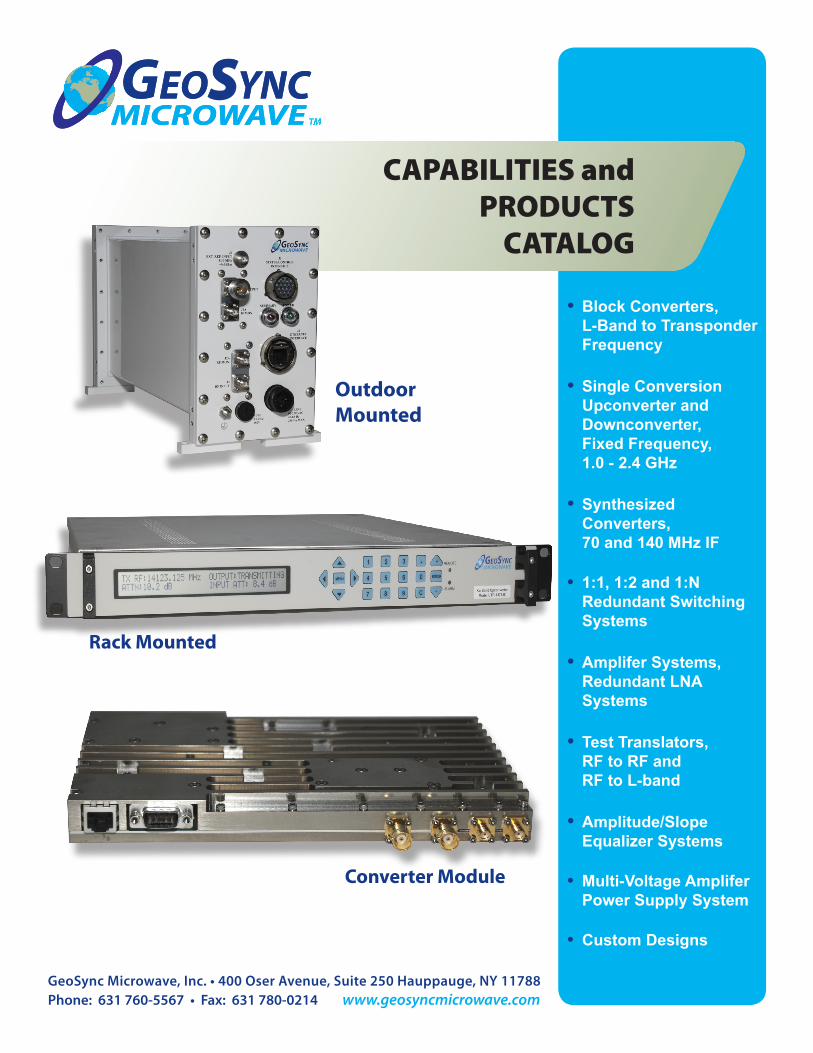
CAPABILITIES andPRODUCTS
CATALOG
• BlockConverters,L-BandtoTransponderFrequency
• SingleConversionUpconverterandDownconverter,FixedFrequency,1.0-2.4GHz
• SynthesizedConverters,70and140MHzIF
• 1:1,1:2and1:NRedundantSwitchingSystems
• AmpliferSystems,RedundantLNASystems
• TestTranslators,RFtoRFandRFtoL-band
• Amplitude/SlopeEqualizerSystems
• Multi-VoltageAmpliferPowerSupplySystem
• CustomDesigns
Outdoor Mounted
Rack Mounted
Converter Module
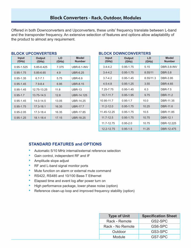
Block Converters - Rack, Outdoor, Modules
STANDARDFEATURESandOPTIONS
Automatic5/10MHzinternal/externalreferenceselection
Gaincontrol,independentRFandIF
Amplitudeslopeadjust
RFandL-bandsignalmonitorports
Mutefunctiononalarmorexternalmutecommand
RS422,RS485and10/100Base-TEthernet
Elapsedtimeandeventlogafterpowerturnon
Highperformancepackage,lowerphasenoise(option)
Referenceclean-uploopandimprovedfrequencystability(option)
•••••••••
BLOCKUPCONVERTERSInput(GHz)
Output(GHz)
LO(GHz)
ModelNumber
0.95-1.525 5.85-6.425 7.375 UBR-6.1-INV
0.95-1.75 5.85-6.65 4.9 UBR-6.25
0.95-1.35 6.7-7.1 5.75 UBR-6.9
0.95-1.45 7.9-8.4 6.95 UBR-8.15
0.95-1.45 12.75-13.25 11.8 UBR-13
0.95-1.7 13.75-14.5 12.8 UBR-14.125
0.95-1.45 14.0-14.5 13.05 UBR-14.25
0.95-1.75 17.3-18.1 16.35 UBR-17.7
0.95-2.05 17.3-18.4 16.35 UBR-17.85
0.95-1.25 18.1-18.4 17.15 UBR-18.25
3.4-4.2 0.95-1.75 5.15 DBR-3.8-INV
3.4-4.2 0.95-1.75 8.55/11 DBR-3.8
3.7-4.2 0.95-1.45 8.55/11.3 DBR-3.95
4.5-4.8 0.95-1.25 3.55 DBR-4.65
7.25-7.75 0.95-1.45 6.3 DBR-7.5
10.7-11.7 0.95-1.95 9.75 DBR-11.2
10.95-11.7 0.95-1.7 10.0 DBR-11.35
11.2-12.0 0.95-1.75 10.25 DBR-11.6
11.45-12.25 0.95-1.75 10.5 DBR-11.85
11.7-12.5 0.95-1.75 10.75 DBR-12.1
11.7-12.75 0.95-2.0 10.75 DBR-12.225
12.2-12.75 0.95-1.5 11.25 DBR-12.475
BLOCKDOWNCONVERTERSInput(GHz)
Output(GHz)
LO(GHz)
ModelNumber
OfferedinbothDownconvertersandUpconverters,theseunits’frequencytranslatebetweenL-bandandthetransponderfrequency.Anextensiveselectionoffeaturesandoptionsallowadaptabilityoftheproducttoalmostanyrequirement.
TypeofUnit Specification SheetRack-Remote GS2-SPC
Rack-NoRemote GS6-SPCOutdoor GS3-SPCModule GS7-SPC
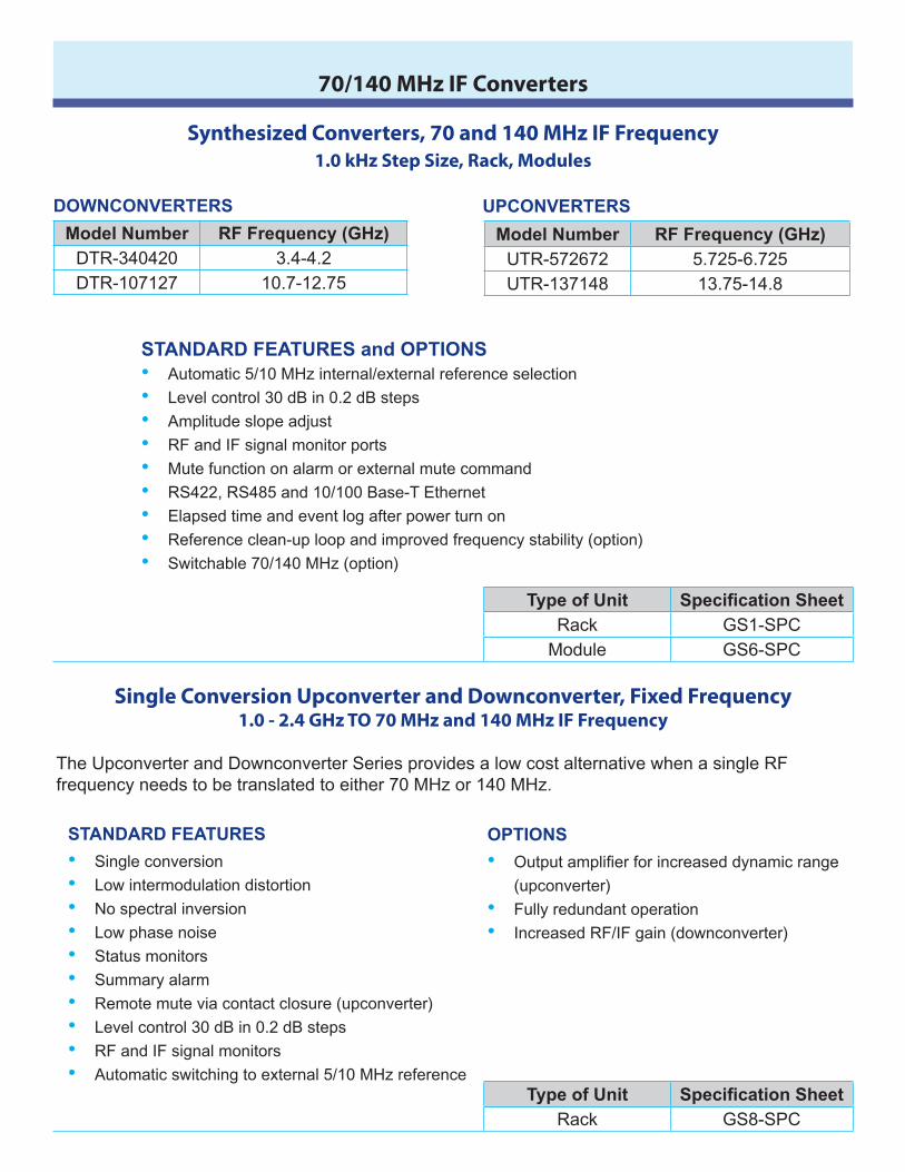
Single Conversion Upconverter and Downconverter, Fixed Frequency 1.0 - 2.4 GHz TO 70 MHz and 140 MHz IF Frequency
TheUpconverterandDownconverterSeriesprovidesalowcostalternativewhenasingleRFfrequencyneedstobetranslatedtoeither70MHzor140MHz.
STANDARDFEATURES
Singleconversion
Lowintermodulationdistortion
Nospectralinversion
Lowphasenoise
Statusmonitors
Summaryalarm
Remotemuteviacontactclosure(upconverter)
Levelcontrol30dBin0.2dBsteps
RFandIFsignalmonitors
Automaticswitchingtoexternal5/10MHzreference
••••••••••
OPTIONS
Output amplifier for increased dynamic range
(upconverter)
Fullyredundantoperation
IncreasedRF/IFgain(downconverter)
•
••
TypeofUnit Specification SheetRack GS8-SPC
Synthesized Converters, 70 and 140 MHz IF Frequency 1.0 kHz Step Size, Rack, Modules
ModelNumber RFFrequency(GHz)DTR-340420 3.4-4.2DTR-107127 10.7-12.75
UPCONVERTERSDOWNCONVERTERS
ModelNumber RFFrequency(GHz)UTR-572672 5.725-6.725UTR-137148 13.75-14.8
STANDARDFEATURESandOPTIONSAutomatic5/10MHzinternal/externalreferenceselection
Levelcontrol30dBin0.2dBsteps
Amplitudeslopeadjust
RFandIFsignalmonitorports
Mutefunctiononalarmorexternalmutecommand
RS422,RS485and10/100Base-TEthernet
Elapsedtimeandeventlogafterpowerturnon
Referenceclean-uploopandimprovedfrequencystability(option)
Switchable70/140MHz(option)
•••••••••
TypeofUnit Specification SheetRack GS1-SPC
Module GS6-SPC
70/140 MHz IF Converters
1:1, 1:2 and 1:N Redundant Switching Systems- Rack MountedFor Block Converters and Synthesized Converters
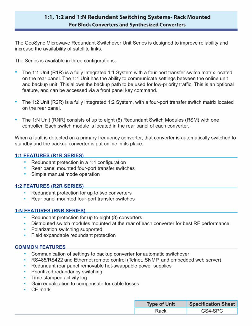
TheGeoSyncMicrowaveRedundantSwitchoverUnitSeriesisdesignedtoimprovereliabilityandincreasetheavailabilityofsatellitelinks.The Series is available in three configurations:• The 1:1 Unit (R1R) is a fully integrated 1:1 System with a four-port transfer switch matrix located
on the rear panel. The 1:1 Unit has the ability to communicate settings between the online unit and backup unit. This allows the backup path to be used for low-priority traffic. This is an optional feature,andcanbeaccessedviaafrontpanelkeycommand.
• The 1:2 Unit (R2R) is a fully integrated 1:2 System, with a four-port transfer switch matrix located
ontherearpanel.• The 1:N Unit (RNR) consists of up to eight (8) Redundant Switch Modules (RSM) with one
controller.Eachswitchmoduleislocatedintherearpanelofeachconverter.Whenafaultisdetectedonaprimaryfrequencyconverter,thatconverterisautomaticallyswitchedtostandbyandthebackupconverterisputonlineinitsplace.1:1FEATURES(R1RSERIES)
• Redundant protection in a 1:1 configuration• Rearpanelmountedfour-porttransferswitches• Simplemanualmodeoperation
1:2FEATURES(R2RSERIES)
• Redundantprotectionforuptotwoconverters• Rearpanelmountedfour-porttransferswitches
1:NFEATURES(RNRSERIES)
• Redundantprotectionforuptoeight(8)converters• DistributedswitchmodulesmountedattherearofeachconverterforbestRFperformance• Polarizationswitchingsupported• Fieldexpandableredundantprotection
COMMONFEATURES
• Communicationofsettingstobackupconverterforautomaticswitchover• RS485/RS422andEthernetremotecontrol(Telnet,SNMP,andembeddedwebserver)• Redundantrearpanelremovablehot-swappablepowersupplies• Prioritizedredundancyswitching• Timestampedactivitylog• Gainequalizationtocompensateforcablelosses• CEmark
TypeofUnit Specification SheetRack GS4-SPC
Redundant LNA SystemsControl Unit (Rack) and Amplifier Plate Assembly (Outdoor)
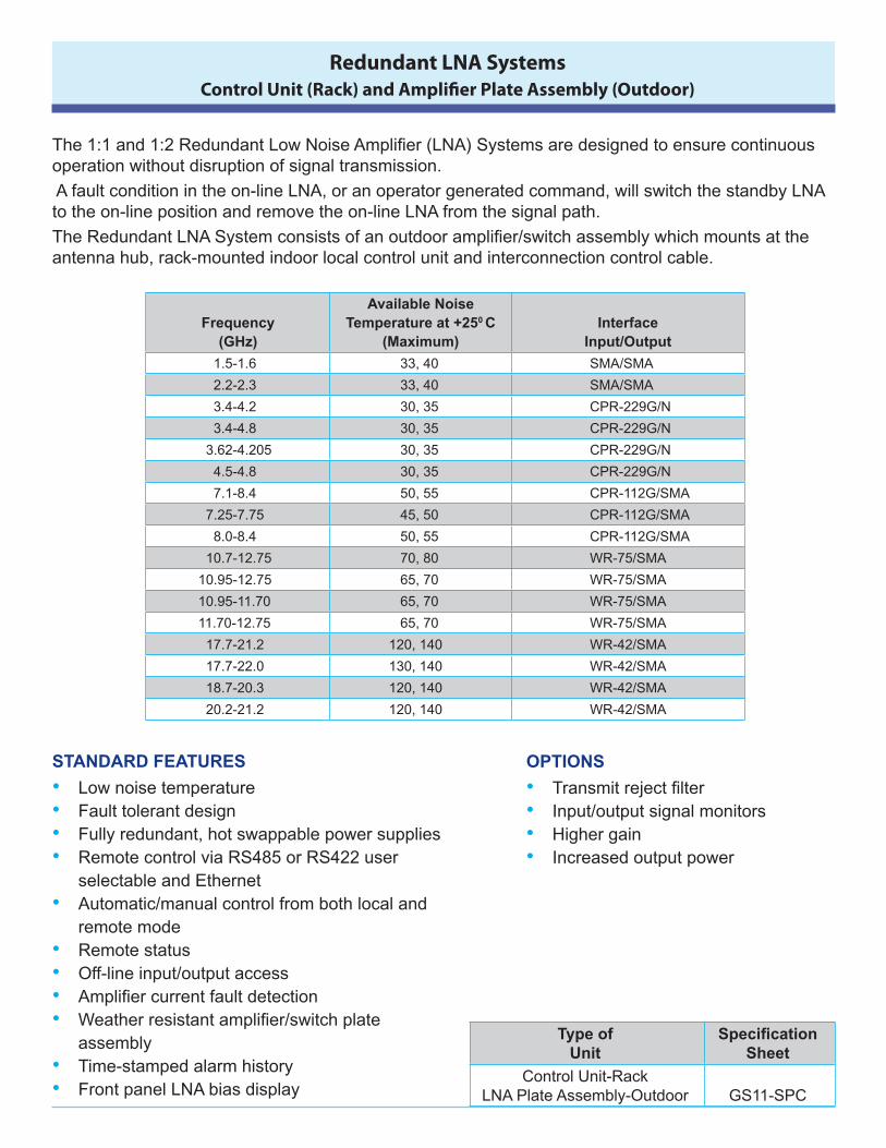
The 1:1 and 1:2 Redundant Low Noise Amplifier (LNA) Systems are designed to ensure continuous operationwithoutdisruptionofsignaltransmission.
Afaultconditionintheon-lineLNA,oranoperatorgeneratedcommand,willswitchthestandbyLNAtotheon-linepositionandremovetheon-lineLNAfromthesignalpath.
The Redundant LNA System consists of an outdoor amplifier/switch assembly which mounts at the antennahub,rack-mountedindoorlocalcontrolunitandinterconnectioncontrolcable.
Frequency
(GHz)
AvailableNoiseTemperatureat+250C
(Maximum)
Interface
Input/Output
1.5-1.6 33,40 SMA/SMA
2.2-2.3 33,40 SMA/SMA
3.4-4.2 30,35 CPR-229G/N
3.4-4.8 30,35 CPR-229G/N
3.62-4.205 30,35 CPR-229G/N
4.5-4.8 30,35 CPR-229G/N
7.1-8.4 50,55 CPR-112G/SMA
7.25-7.75 45,50 CPR-112G/SMA
8.0-8.4 50,55 CPR-112G/SMA
10.7-12.75 70,80 WR-75/SMA
10.95-12.75 65,70 WR-75/SMA
10.95-11.70 65,70 WR-75/SMA
11.70-12.75 65,70 WR-75/SMA
17.7-21.2 120,140 WR-42/SMA
17.7-22.0 130,140 WR-42/SMA
18.7-20.3 120,140 WR-42/SMA
20.2-21.2 120,140 WR-42/SMA
STANDARDFEATURES
LownoisetemperatureFaulttolerantdesignFullyredundant,hotswappablepowersuppliesRemotecontrolviaRS485orRS422user
selectableandEthernetAutomatic/manualcontrolfrombothlocaland
remotemodeRemotestatusOff-lineinput/outputaccessAmplifier current fault detectionWeather resistant amplifier/switch plate
assemblyTime-stampedalarmhistoryFrontpanelLNAbiasdisplay
••••
•
••••
••
OPTIONS
Transmit reject filter Input/outputsignalmonitorsHighergainIncreasedoutputpower
••••
TypeofUnit
SpecificationSheet
ControlUnit-RackLNAPlateAssembly-Outdoor GS11-SPC
Test Translators – RF to RF and RF to L-Band Rack and Outdoor Mount
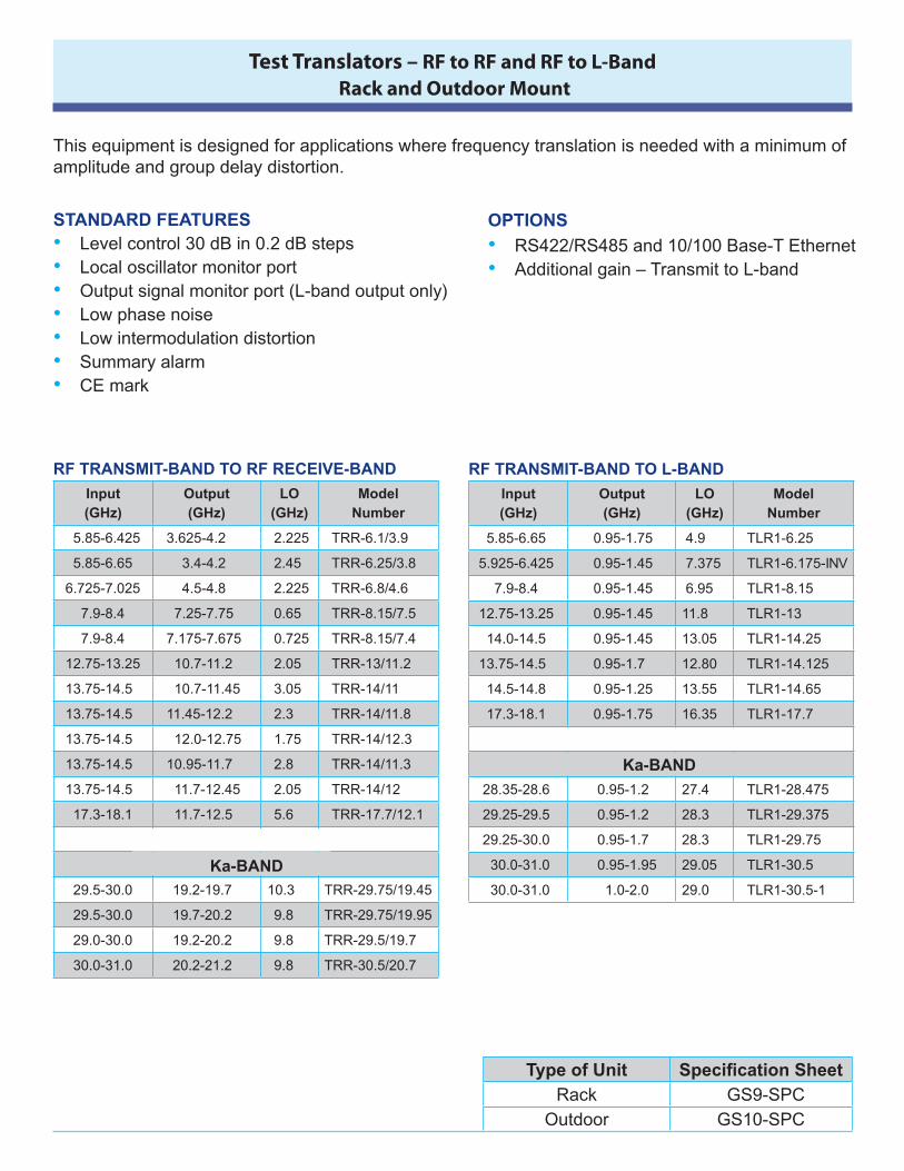
Thisequipmentisdesignedforapplicationswherefrequencytranslationisneededwithaminimumofamplitudeandgroupdelaydistortion.
STANDARDFEATURESLevelcontrol30dBin0.2dBstepsLocaloscillatormonitorportOutputsignalmonitorport(L-bandoutputonly)LowphasenoiseLowintermodulationdistortionSummaryalarmCEmark
•••••••
RS422/RS485and10/100Base-TEthernetAdditionalgain–TransmittoL-band
••
RFTRANSMIT-BANDTORFRECEIVE-BAND
Input(GHz)
Output(GHz)
LO(GHz)
ModelNumber
5.85-6.425 3.625-4.2 2.225 TRR-6.1/3.9
5.85-6.65 3.4-4.2 2.45 TRR-6.25/3.8
6.725-7.025 4.5-4.8 2.225 TRR-6.8/4.6
7.9-8.4 7.25-7.75 0.65 TRR-8.15/7.5
7.9-8.4 7.175-7.675 0.725 TRR-8.15/7.4
12.75-13.25 10.7-11.2 2.05 TRR-13/11.2
13.75-14.5 10.7-11.45 3.05 TRR-14/11
13.75-14.5 11.45-12.2 2.3 TRR-14/11.8
13.75-14.5 12.0-12.75 1.75 TRR-14/12.3
13.75-14.5 10.95-11.7 2.8 TRR-14/11.3
13.75-14.5 11.7-12.45 2.05 TRR-14/12
17.3-18.1 11.7-12.5 5.6 TRR-17.7/12.1
29.5-30.0 19.2-19.7 10.3 TRR-29.75/19.45
29.5-30.0 19.7-20.2 9.8 TRR-29.75/19.95
29.0-30.0 19.2-20.2 9.8 TRR-29.5/19.7
30.0-31.0 20.2-21.2 9.8 TRR-30.5/20.7
Ka-BAND
OPTIONS
RFTRANSMIT-BANDTOL-BAND
Input(GHz)
Output(GHz)
LO(GHz)
ModelNumber
5.85-6.65 0.95-1.75 4.9 TLR1-6.25
5.925-6.425 0.95-1.45 7.375 TLR1-6.175-INV
7.9-8.4 0.95-1.45 6.95 TLR1-8.15
12.75-13.25 0.95-1.45 11.8 TLR1-13
14.0-14.5 0.95-1.45 13.05 TLR1-14.25
13.75-14.5 0.95-1.7 12.80 TLR1-14.125
14.5-14.8 0.95-1.25 13.55 TLR1-14.65
17.3-18.1 0.95-1.75 16.35 TLR1-17.7
28.35-28.6 0.95-1.2 27.4 TLR1-28.475
29.25-29.5 0.95-1.2 28.3 TLR1-29.375
29.25-30.0 0.95-1.7 28.3 TLR1-29.75
30.0-31.0 0.95-1.95 29.05 TLR1-30.5
30.0-31.0 1.0-2.0 29.0 TLR1-30.5-1
Ka-BAND
TypeofUnit Specification SheetRack GS9-SPC
Outdoor GS10-SPC
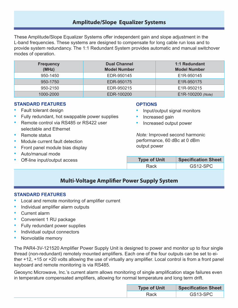
TheseAmplitude/SlopeEqualizerSystemsofferindependentgainandslopeadjustmentintheL-bandfrequencies.Thesesystemsaredesignedtocompensateforlongcablerunlossandtoprovide system redundancy. The 1:1 Redundant System provides automatic and manual switchover modesofoperation.
Amplitude/Slope Equalizer Systems
Frequency(MHz)
DualChannelModelNumber
1:1RedundantModelNumber
950-1450 EDR-950145 E1R-950145
950-1750 EDR-950175 E1R-950175
950-2150 EDR-950215 E1R-950215
1000-2000 EDR-100200 E1R-100200(Note)
STANDARDFEATURESFaulttolerantdesignFullyredundant,hotswappablepowersuppliesRemotecontrolviaRS485orRS422user
selectableandEthernetRemotestatusModulecurrentfaultdetectionFrontpanelmodulebiasdisplayAuto/manualmodeOff-lineinput/outputaccess
•••
•••••
STANDARDFEATURESLocal and remote monitoring of amplifier currentIndividual amplifier alarm outputsCurrentalarmConvenient1RUpackageFullyredundantpowersuppliesIndividualoutputconnectorsNonvolatilememory
•••••••
Input/outputsignalmonitorsIncreasedgainIncreasedoutputpower
•••
OPTIONS
Multi-Voltage Amplifier Power Supply System
TypeofUnit Specification SheetRack GS12-SPC
TypeofUnit Specification SheetRack GS13-SPC
The PAR4-3V-121520 Amplifier Power Supply Unit is designed to power and monitor up to four single thread (non-redundant) remotely mounted amplifiers. Each one of the four outputs can be set to ei-ther +12, +15 or +20 volts allowing the use of virtually any amplifier. Local control is from a front panel keyboardandremotemonitoringisviaRS485.
Geosync Microwave, Inc.’s current alarm allows monitoring of single amplification stage failures even in temperature compensated amplifiers, allowing for normal temperature and long term drift.
Note:Improvedsecondharmonicperformance,60dBcat0dBmoutputpower

GeoSync Microwave, Inc. • 400 Oser Avenue, Suite 250 Hauppauge, NY 11788Phone: 631 760-5567 • Fax: 631 780-0214 www.geosyncmicrowave.com B1 9/09
GEOSYNCGEOSYNCTM
CUSTOMDESIGNSGeosyncMicrowave,Inc.’sstrongtechnicalteamispreparedtodesignunitsbuilttoyourspecialmechanicalandelectricalrequirements.ThisincludesbothRFandsoftwarerequirements.Duringthepast39+yearsourtechnicalteam’sperformancein“special”technicalareassuchaslowFrequencySourceAllenVarianceandPhaseStability(asopposedtofrequencystability)havebecomewellknownintheindustry.
PERSONNELandHISTORYGeosyncMicrowave,Inc.wasformedinMarch2008byArthurFaverio,afounderandaformerPresidentofMITEQInc.Duringatimeperiodof30+years,hemanagedatechnicalteamthatwaslargelyresponsiblefordevelopingtheSATCOMproductlineatthiscompany.Thiswasaccomplishedwithastrongmanagementemphasisonproductreliability,customerserviceandpromotionofengineeringingenuity.JoiningArthurFaveriofromMITEQInc.,andnowtheengineeringteamatGeosyncMicrowave,Inc.are: TimothyJahn,Principal Engineer, RF Assemblies IsraelMoskovitch,Principal Engineer, RF Assemblies M.F.Zahidi,Principal Engineer, Frequency SourcesThiskeyengineeringteamwillbedevelopingthe“nextgeneration”ofSATCOMproducts.Product emphasis is on:
HighreliabilityFullycontainedRFmodulesallowingsmallsizefor“standalone”modules.Inclusionof“optionalperformanceoffering”intostandardunits.Customdesignsforcustomersofferedatreasonablecost.
FACILITY3900 square feet of modern office spaceEngineeringdesignaidsAssembly/testfacilitiesPrototypemachiningInventory/manufacturingcontrol
••••
•••••