Embed Size (px)
Citation preview
ISO9001:2008 Document No: BS-M-7.3-1 Version No:1.3 Date Effective: 01-4-2014
Document Title:Master List of Drawings of Bridges & Structures Directorate, RDSO.
Prepared By: ADE/SB-1 Issued By: DBS/SB-I Page 1 of 55
Title : Master List of Drawings of Bridges & Structures Directorate, RDSO.
BS-28
(Revision 16, version 2)
May 2014
Prepared by Checked by Approved by
ADE/B&S/SS DBS/SB-I EDBS
ISO9001:2008 Document No: BS-M-7.3-1 Version No:1.3 Date Effective: 01-4-2014
Document Title:Master List of Drawings of Bridges & Structures Directorate, RDSO.
Prepared By: ADE/SB-1 Issued By: DBS/SB-I Page 2 of 55
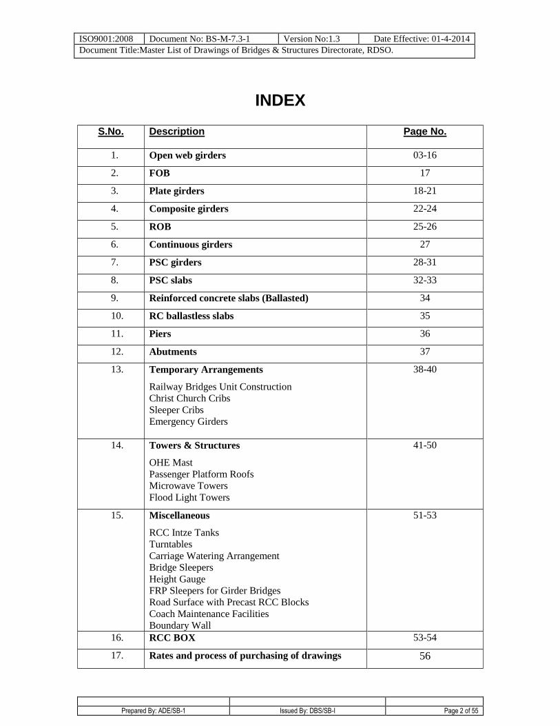
INDEX
S.No. Description Page No.
1. Open web girders 03-16
2. FOB 17
3. Plate girders 18-21
4. Composite girders 22-24
5. ROB 25-26
6. Continuous girders 27
7. PSC girders 28-31
8. PSC slabs 32-33
9. Reinforced concrete slabs (Ballasted) 34
10. RC ballastless slabs 35
11. Piers 36
12. Abutments 37
13. Temporary Arrangements
Railway Bridges Unit Construction
Christ Church Cribs
Sleeper Cribs
Emergency Girders
38-40
14. Towers & Structures
OHE Mast
Passenger Platform Roofs
Microwave Towers
Flood Light Towers
41-50
15. Miscellaneous
RCC Intze Tanks
Turntables
Carriage Watering Arrangement
Bridge Sleepers
Height Gauge
FRP Sleepers for Girder Bridges
Road Surface with Precast RCC Blocks
Coach Maintenance Facilities
Boundary Wall
51-53
16. RCC BOX 53-54
17. Rates and process of purchasing of drawings 56
ISO9001:2008 Document No: BS-M-7.3-1 Version No:1.3 Date Effective: 01-4-2014
Document Title:Master List of Drawings of Bridges & Structures Directorate, RDSO.
Prepared By: ADE/SB-1 Issued By: DBS/SB-I Page 3 of 55
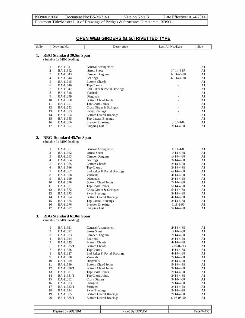
OPEN WEB GIRDERS (B.G.) RIVETTED TYPE
S.No. Drawing No. Description Last Alt.No./Date Size
1. RBG Standard 30.5m Span (Suitable for MBG loading)
1 BA-11341 General Arrangement - A1
2 BA-11342 Stress Sheet 1/ 14-4-87 A1
3 BA-11343 Camber Diagram 1/ 14-4-88 A1
4 BA-11344 Bearings 4/ 14-4-88 A1
5 BA-11345 Bottom Chords - A1
6 BA-11346 Top Chords - A1
7 BA-11347 End Raker & Portal Bracings - A1
8 BA-11348 Verticals - A1
9 BA-11349 Diagonals - A1
10 BA-11350 Bottom Chord Joints - A1
11 BA-11351 Top Chord Joints - A1 12 BA-11352 Cross Girder & Stringers - A1
13 BA-11353 Sway Bracings - A1
14 BA-11354 Bottom Lateral Bracings - A1 15 BA-11355 Top Lateral Bracings - A1
16 BA-11356 Erection Drawing 3/ 14-4-88 A1 17 BA-11357 Shipping List 2/ 14-4-88 A1
2. RBG Standard 45.7m Span (Suitable for MBG loading)
1 BA-11361 General Arrangement 1/ 14-4-88 A1
2 BA-11362 Stress Sheet 1/ 14-4-88 A1
3 BA-11363 Camber Diagram 1/ 14-4-88 A1
4 BA-11364 Bearings 3/ 14-4-88 A1
5 BA-11365 Bottom Chords 2/ 14-4-88 A1
6 BA-11366 Top Chords 3/ 14-4-88 A1
7 BA-11367 End Raker & Portal Bracings 6/ 14-4-88 A1
8 BA-11368 Verticals 4/ 14-4-88 A1
9 BA-11369 Diagonals 2/ 14-4-88 A1
10 BA-11370 Bottom Chord Joints 7/ 14-4-88 A1 11 BA-11371 Top Chord Joints 5/ 14-4-88 A1
12 BA-11372 Cross Girder & Stringers 5/ 14-4-88 A1
13 BA-11373 Sway Bracings 5/ 14-4-88 A1 14 BA-11374 Bottom Lateral Bracings 4/ 14-4-88 A1
15 BA-11375 Top Lateral Bracings 2/ 14-4-88 A1
16 BA-11376 Erection Drawing 6/18-2-93 A1 17 BA-11377 Shipping List 5/ 14-4-88 A1
3. RBG Standard 61.0m Span (Suitable for MBG loading)
1
BA-11321
General Arrangement
2/ 14-4-88
A1 2 BA-11322 Stress Sheet 1/ 14-4-88 A1
3 BA-11323 Camber Diagram 2/ 14-4-88 A1
4 BA-11324 Bearings 3/ 14-4-88 A1 5 BA-11325 Bottom Chords 4/ 14-4-88 A1
6 BA-11325/1 Bottom Chords 5/ 09-07-93 A1
7 BA-11326 Top Chords 4/ 14-4-88 A1 8 BA-11327 End Raker & Portal Bracings 4/ 14-4-88 A1
9 BA-11328 Verticals 2/ 14-4-88 A1
10 BA-11329 Diagonals 3/ 14-4-88 A1 11 BA-11330 Bottom Chord Joints 5/ 14-4-88 A1
12 BA-11330/1 Bottom Chord Joints 3/ 14-4-88 A1
13 BA-11331 Top Chord Joints 2/ 14-4-88 A1 14 BA-11331/1 Top Chord Joints 3/ 14-4-88 A1
15 BA-11332 Cross Girders 3/ 14-4-88 A1
16 BA-11333 Stringers 2/ 14-4-88 A1 17 BA-11333/1 Stringers 3/ 14-4-88 A1
18 BA-11334 Sway Bracings 2/ 14-4-88 A1
19 BA-11335 Bottom Lateral Bracings 2/ 14-4-88 A1 20 BA-11335/1 Bottom Lateral Bracings 4/ 06-08-90 A1
ISO9001:2008 Document No: BS-M-7.3-1 Version No:1.3 Date Effective: 01-4-2014
Document Title:Master List of Drawings of Bridges & Structures Directorate, RDSO.
Prepared By: ADE/SB-1 Issued By: DBS/SB-I Page 4 of 55
S.No Drawing No. Description Last Alt.No./Date Size
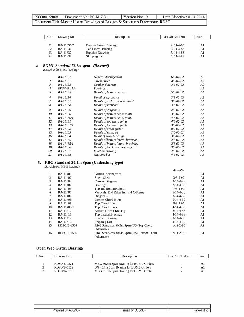
21 BA-11335/2 Bottom Lateral Bracing 4/ 14-4-88 A1 22 BA-11336 Top Lateral Bracing 2/ 14-4-88 A1
23 BA-11337 Erection Drawing 5/ 14-4-88 A1
24 BA-11338 Shipping List 5/ 14-4-88 A1
4. BGML Standard 76.2m span (Rivetted) (Suitable for MBG loading)
1 BA-11151 General Arrangement 6/6-02-02 A0
2 BA-11152 Stress sheet 4/6-02-02 A0
3 BA-11153 Camber diagram 3/6-02-02 A0
4 RDSO/B-1524 Bearings - A1 5 BA-11155 Details of bottom chords 5/6-02-02 A1
6 BA-11156 Detail of top chords 3/6-02-02 A1
7 BA-11157 Details of end raker and portal 3/6-02-02 A1
8 BA-11158 Details of verticals 3/6-02-02 A1
9 BA-11159 Details of diagonals 2/6-02-02 A1
10 BA-11160 Details of bottom chord joints 3/6-02-02 A1
11 BA-11160/1 Details of bottom chord joints 4/6-02-02 A1
12 BA-11161 Details of top chord joints 4/6-02-02 A1 13 BA-11161/1 Details of top chord joints 3/6-02-02 A1
14 BA-11162 Details of cross girder 8/6-02-02 A1
15 BA-11163 Details of stringers 7/6-02-02 A1 16 BA-11164 Detail of sway bracings. 3/6-02-02 A1
17 BA-11165 Details of bottom lateral bracings. 2/6-02-02 A1
18 BA-11165/1 Details of bottom lateral bracings. 2/6-02-02 A1 19 BA-11166 Details of top lateral bracings 3/6-02-02 A1
20 BA-11167 Erection drawing 4/6-02-02 A1
21 BA-11168 Shipping list 4/6-02-02 A1
5. RBG Standard 30.5m Span (Underslung type) (Suitable for MBG loading)
1
BA-11401
General Arrangement
4/3-5-97
A1
2 BA-11402 Stress Sheet 3/8-5-97 A1 3 BA-11403 Camber Diagram 2/14-4-88 A1
4 BA-11404 Bearings 2/14-4-88 A1
5 BA-11405 Top and Bottom Chords 7/8-5-97 A1 6 BA-11406 Verticals, End Raker Int. and X-Frame 5/14-4-88 A1
7 BA-11407 Diagonals 3/14-4-88 A1
8 BA-11408 Bottom Chord Joints 6/14-4-88 A1 9 BA-11409 Top Chord Joints 5/8-5-97 A1
10 BA-11409/1 Top Chord Joints 4/14-4-88 A1
11 BA-11410 Bottom Lateral Bracings 2/14-4-88 A1 12 BA-11411 Top Lateral Bracings 4/14-4-88 A1
13 BA-11412 Erection Drawing 3/14-4-88 A1
14 BA-11413 Shipping List 3/14-4-88 A1 15 RDSO/B-1504 RBG Standards 30.5m Span (US) Top Chord
(Alternate)
1/11-2-98 A1
16 RDSO/B-1505 RBG Standards 30.5m Span (US) Bottom Chord
(Alternate)
2/11-2-98 A1
Open Web Girder Bearings
S.No. Drawing No. Description Last Alt.No./Date Size
1 RDSO/B-1521 MBG 30.5m Span Bearing for BGML Girders - A1
2 RDSO/B-1522 BG 45.7m Span Bearing for BGML Girders - A1
3 RDSO/B-1523 MBG 61.0m Span Bearing for BGML Girder - A1
ISO9001:2008 Document No: BS-M-7.3-1 Version No:1.3 Date Effective: 01-4-2014
Document Title:Master List of Drawings of Bridges & Structures Directorate, RDSO.
Prepared By: ADE/SB-1 Issued By: DBS/SB-I Page 5 of 55
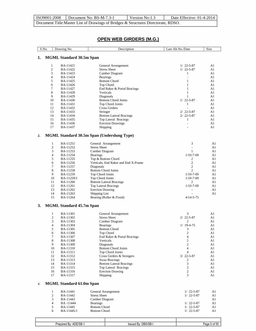
OPEN WEB GIRDERS (M.G.)
S.No. Drawing No. Description Last Alt.No./Date Size
1. MGML Standard 30.5m Span
1
BA-11421
General Arrangement
1/ 22-5-87
A1
2 BA-11422 Stress Sheet 1/ 22-5-87 A1
3 BA-11423 Camber Diagram 1 A1
4 BA-11424 Bearings - A1
5 BA-11425 Bottom Chord 1 A1
6 BA-11426 Top Chord 1 A1
7 BA-11427 End Raker & Portal Bracings 1 A1
8 BA-11428 Verticals 1 A1
9 BA-11429 Diagonals 1 A1
10 BA-11430 Bottom Chord Joints 1/ 22-5-87 A1
11 BA-11431 Top Chord Joints 1 A1
12 BA-11432 Cross Girders - A1
13 BA-11433 Stringer 2/ 22-5-87 A1
14 BA-11434 Bottom Lateral Bracings 2/ 22-5-87 A1
15 BA-11435 Top Lateral Bracings 1 A1
16 BA-11436 Erection Drawings - A1
17 BA-11437 Shipping - A1
2. MGML Standard 30.5m Span (Underslung Type)
1 BA-11251 General Arrangement 3 A1 2 BA-11252 Stress Sheet - A1
3 BA-11253 Camber Diagram 1 A1
4 BA-11254 Bearings 1/10-7-69 A1 5 BA-11255 Top & Bottom Chord 2 A1
6 BA-11256 Verticals, End Raker and End X-Frame 2 A1
7 BA-11257 Diagonals 2 A1 8 BA-11258 Bottom Chord Joints 2 A1
9 BA-11259 Top Chord Joints 1/10-7-69 A1
10 BA-11259/1 Top Chord Joints 1/10-7-69 A1 11 BA-11260 Bottom Lateral Bracings 2 A1
12 BA-11261 Top Lateral Bracings 1/10-7-69 A1
13 BA-11262 Erection Drawing - A1 14 BA-11263 Shipping List - A1
15 BA-11264 Bearing (Roller & Fixed) 4/14-5-75
3. MGML Standard 45.7m Span
1
BA-11301
General Arrangement
3
A1
2 BA-11302 Stress Sheet 2/ 22-5-87 A1
3 BA-11303 Camber Diagram 2 A1
4 BA-11304 Bearings 1/ 19-4-75 A1
5 BA-11305 Bottom Chord 3 A1
6 BA-11306 Top Chord 2 A1
7 BA-11307 End Raker & Portal Bracings 4 A1
8 BA-11308 Verticals 2 A1
9 BA-11309 Diagonals 2 A1
10 BA-11310 Bottom Chord Joints 4 A1
11 BA-11311 Top Chord Joints 4 A1
12 BA-11312 Cross Girders & Stringers 3/ 22-5-87 A1
13 BA-11313 Sway Bracings 2 A1
14 BA-11314 Bottom Lateral Bracings 3 A1
15 BA-11315 Top Lateral Bracings 2 A1
16 BA-11316 Erection Drawing 2 A1
17 BA-11317 Shipping 3 A1
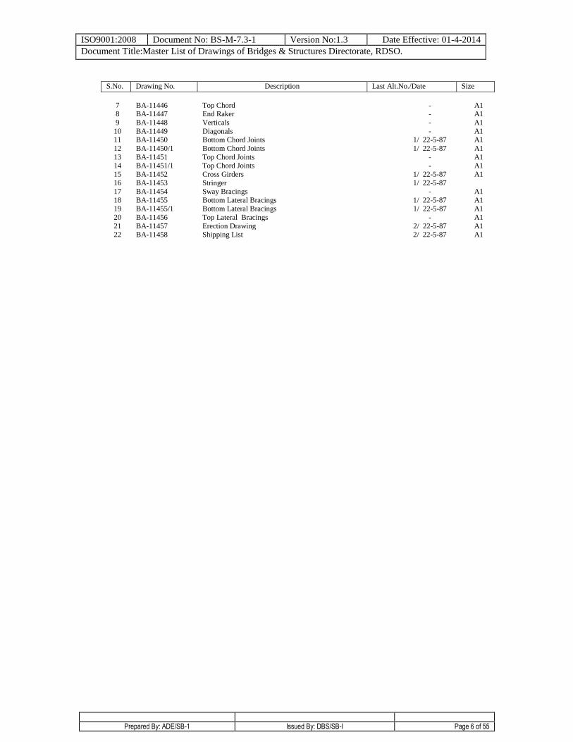
4. MGML Standard 61.0m Span
1
BA-11441
General Arrangement
1/ 22-5-87
A1
2 BA-11442 Stress Sheet 1/ 22-5-87 A1
3 BA-11443 Camber Diagram - A1
4 BA -11444 Bearings 1/ 22-5-87 A1
5 BA-11445 Bottom Chord 1/ 22-5-87 A1
6 BA-11445/1 Bottom Chord 1/ 22-5-87 A1
ISO9001:2008 Document No: BS-M-7.3-1 Version No:1.3 Date Effective: 01-4-2014
Document Title:Master List of Drawings of Bridges & Structures Directorate, RDSO.
Prepared By: ADE/SB-1 Issued By: DBS/SB-I Page 6 of 55
S.No. Drawing No. Description Last Alt.No./Date Size
7 BA-11446 Top Chord - A1
8 BA-11447 End Raker - A1
9 BA-11448 Verticals - A1
10 BA-11449 Diagonals - A1
11 BA-11450 Bottom Chord Joints 1/ 22-5-87 A1
12 BA-11450/1 Bottom Chord Joints 1/ 22-5-87 A1
13 BA-11451 Top Chord Joints - A1
14 BA-11451/1 Top Chord Joints - A1
15 BA-11452 Cross Girders 1/ 22-5-87 A1
16 BA-11453 Stringer 1/ 22-5-87
17 BA-11454 Sway Bracings - A1
18 BA-11455 Bottom Lateral Bracings 1/ 22-5-87 A1
19 BA-11455/1 Bottom Lateral Bracings 1/ 22-5-87 A1
20 BA-11456 Top Lateral Bracings - A1
21 BA-11457 Erection Drawing 2/ 22-5-87 A1
22 BA-11458 Shipping List 2/ 22-5-87 A1
ISO9001:2008 Document No: BS-M-7.3-1 Version No:1.3 Date Effective: 01-4-2014
Document Title:Master List of Drawings of Bridges & Structures Directorate, RDSO.
Prepared By: ADE/SB-1 Issued By: DBS/SB-I Page 7 of 55
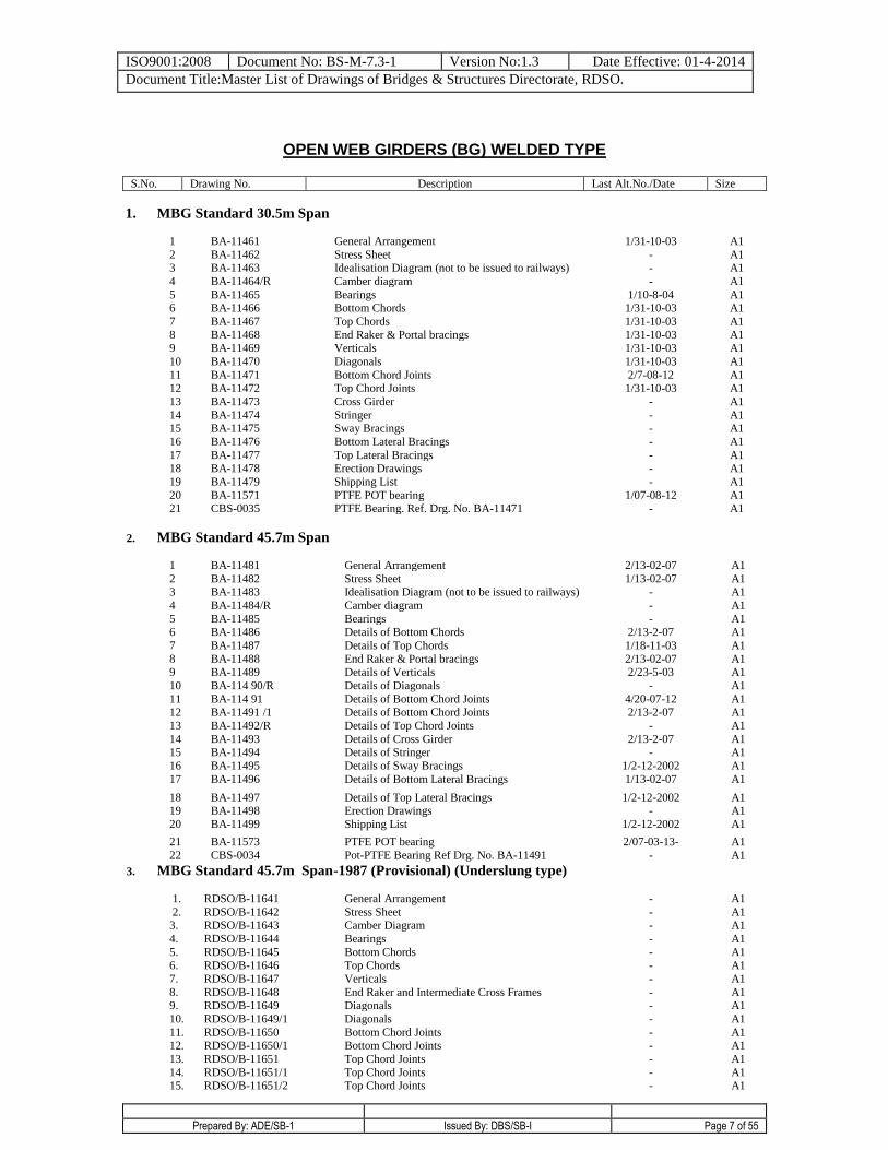
OPEN WEB GIRDERS (BG) WELDED TYPE
S.No. Drawing No. Description Last Alt.No./Date Size
1. MBG Standard 30.5m Span
1 BA-11461 General Arrangement 1/31-10-03 A1
2 BA-11462 Stress Sheet - A1 3 BA-11463 Idealisation Diagram (not to be issued to railways) - A1
4 BA-11464/R Camber diagram - A1
5 BA-11465 Bearings 1/10-8-04 A1 6 BA-11466 Bottom Chords 1/31-10-03 A1
7 BA-11467 Top Chords 1/31-10-03 A1
8 BA-11468 End Raker & Portal bracings 1/31-10-03 A1 9 BA-11469 Verticals 1/31-10-03 A1
10 BA-11470 Diagonals 1/31-10-03 A1
11 BA-11471 Bottom Chord Joints 2/7-08-12 A1 12 BA-11472 Top Chord Joints 1/31-10-03 A1
13 BA-11473 Cross Girder - A1
14 BA-11474 Stringer - A1 15 BA-11475 Sway Bracings - A1
16 BA-11476 Bottom Lateral Bracings - A1
17 BA-11477 Top Lateral Bracings - A1 18 BA-11478 Erection Drawings - A1
19 BA-11479 Shipping List - A1
20 BA-11571 PTFE POT bearing 1/07-08-12 A1 21 CBS-0035 PTFE Bearing. Ref. Drg. No. BA-11471 - A1
2. MBG Standard 45.7m Span
1 BA-11481 General Arrangement 2/13-02-07 A1
2 BA-11482 Stress Sheet 1/13-02-07 A1 3 BA-11483 Idealisation Diagram (not to be issued to railways) - A1
4 BA-11484/R Camber diagram - A1
5 BA-11485 Bearings - A1 6 BA-11486 Details of Bottom Chords 2/13-2-07 A1
7 BA-11487 Details of Top Chords 1/18-11-03 A1
8 BA-11488 End Raker & Portal bracings 2/13-02-07 A1 9 BA-11489 Details of Verticals 2/23-5-03 A1
10 BA-114 90/R Details of Diagonals - A1
11 BA-114 91 Details of Bottom Chord Joints 4/20-07-12 A1 12 BA-11491 /1 Details of Bottom Chord Joints 2/13-2-07 A1
13 BA-11492/R Details of Top Chord Joints - A1
14 BA-11493 Details of Cross Girder 2/13-2-07 A1 15 BA-11494 Details of Stringer - A1
16 BA-11495 Details of Sway Bracings 1/2-12-2002 A1
17 BA-11496 Details of Bottom Lateral Bracings 1/13-02-07 A1
18 BA-11497 Details of Top Lateral Bracings 1/2-12-2002 A1 19 BA-11498 Erection Drawings - A1
20 BA-11499 Shipping List 1/2-12-2002 A1
21 BA-11573 PTFE POT bearing 2/07-03-13- A1
22 CBS-0034 Pot-PTFE Bearing Ref Drg. No. BA-11491 - A1
3. MBG Standard 45.7m Span-1987 (Provisional) (Underslung type)
1. RDSO/B-11641 General Arrangement - A1
2. RDSO/B-11642 Stress Sheet - A1 3. RDSO/B-11643 Camber Diagram - A1
4. RDSO/B-11644 Bearings - A1
5. RDSO/B-11645 Bottom Chords - A1 6. RDSO/B-11646 Top Chords - A1
7. RDSO/B-11647 Verticals - A1
8. RDSO/B-11648 End Raker and Intermediate Cross Frames - A1 9. RDSO/B-11649 Diagonals - A1
10. RDSO/B-11649/1 Diagonals - A1
11. RDSO/B-11650 Bottom Chord Joints - A1 12. RDSO/B-11650/1 Bottom Chord Joints - A1
13. RDSO/B-11651 Top Chord Joints - A1
14. RDSO/B-11651/1 Top Chord Joints - A1 15. RDSO/B-11651/2 Top Chord Joints - A1
ISO9001:2008 Document No: BS-M-7.3-1 Version No:1.3 Date Effective: 01-4-2014
Document Title:Master List of Drawings of Bridges & Structures Directorate, RDSO.
Prepared By: ADE/SB-1 Issued By: DBS/SB-I Page 8 of 55
16. RDSO/B-11652 Bottom Lateral Bracings - A1
17. RDSO/B-11653 Top Lateral Bracings - A1 18. RDSO/B-11654 Erection Drawing - A1
19. RDSO/B-11655 Shipping List - A1
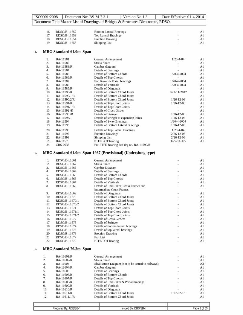
4. MBG Standard 61.0m Span
1. BA-11581 General Arrangement 1/20-4-04 A1
2. BA-11582 Stress Sheet - A1 3. BA-11583/R Camber diagram - A1
4. BA-11584 Details of Bearings - A1
5. BA-11585 Details of Bottom Chords 1/20-4-2004 A1 6. BA-11586/R Details of Top Chords - A1
7. BA-11587 End Raker & Portal bracings 1/20-4-2004 A1
8. BA-11588 Details of Verticals 1/20-4-2004 A1 9. BA-11589/R Details of Diagonals - A1
10. BA-11590/R Details of Bottom Chord Joints 1/27-11-2012 A1
11. BA-11590/1/R Details of Bottom Chord Joints - A1
12. BA-11590/2/R Details of Bottom Chord Joints 1/26-12-06 A1
13. BA-11591/R Details of Top Chord Joints 1/26-12-06 A1
14. BA-11591/1/R Details of Top Chord Joints - A1 15. BA-11592 /R Details of Cross Girder - A1
16. BA-11593 /R Details of Stringer 1/26-12-06 A1
17. BA-11593/1 Details of stringer at expansion joints 1/26-12-06 A1 18. BA-11594 Details of Sway Bracings 1/20-4-2004 A1
19. BA-11595 Details of Bottom Lateral Bracings 1/26-12-06 A1
20. BA-11596 Details of Top Lateral Bracings 1/20-4-04 A1
21. BA-11597 Erection Drawings 2/26-12-06 A1 22. BA-11598 Shipping List 2/26-12-06 A1
23. BA-11575 PTFE POT bearing 1/27-11-12- A1
24. CBS-0036 Pot-PTFE Bearing Ref drg no. BA-11590/R -
5. MBG Standard 61.0m Span-1987 (Provisional) (Underslung type)
1. RDSO/B-11661 General Arrangement - A1
2. RDSO/B-11662 Stress Sheet - A1
3. RDSO/B-11663 Camber Diagram - A1 4. RDSO/B-11664 Details of Bearings - A1
5. RDSO/B-11665 Details of Bottom Chords - A1
6. RDSO/B-11666 Details of Top Chords - A1 7. RDSO/B-11667 Details of Verticals - A1
8. RDSO/B-11668 Details of End Raker, Cross Frames and
Intermediate Cross Frames
- A1
9. RDSO/B-11669 Details of Diagonals - A1
10. RDSO/B-11670 Details of Bottom Chord Joints - A1
11. RDSO/B-11670/1 Details of Bottom Chord Joints - A1 12. RDSO/B-11670/2 Details of Bottom Chord Joints - A1
13. RDSO/B-11671 Details of Top Chord Joints - A1
14. RDSO/B-11671/1 Details of Top Chord Joints - A1 15. RDSO/B-11671/2 Details of Top Chord Joints - A1
16. RDSO/B-11672 Details of Cross Girders - A1
17 RDSO/B-11673 Details of Stringer - A1 18 RDSO/B-11674 Details of bottom lateral bracings - A1
19 RDSO/B-11675 Details of top lateral bracings - A1
20 RDSO/B-11676 Erection Drawing - A1 21 RDSO/B-11677 Part List - A1
22 RDSO/B-11579 PTFE POT bearing - A1
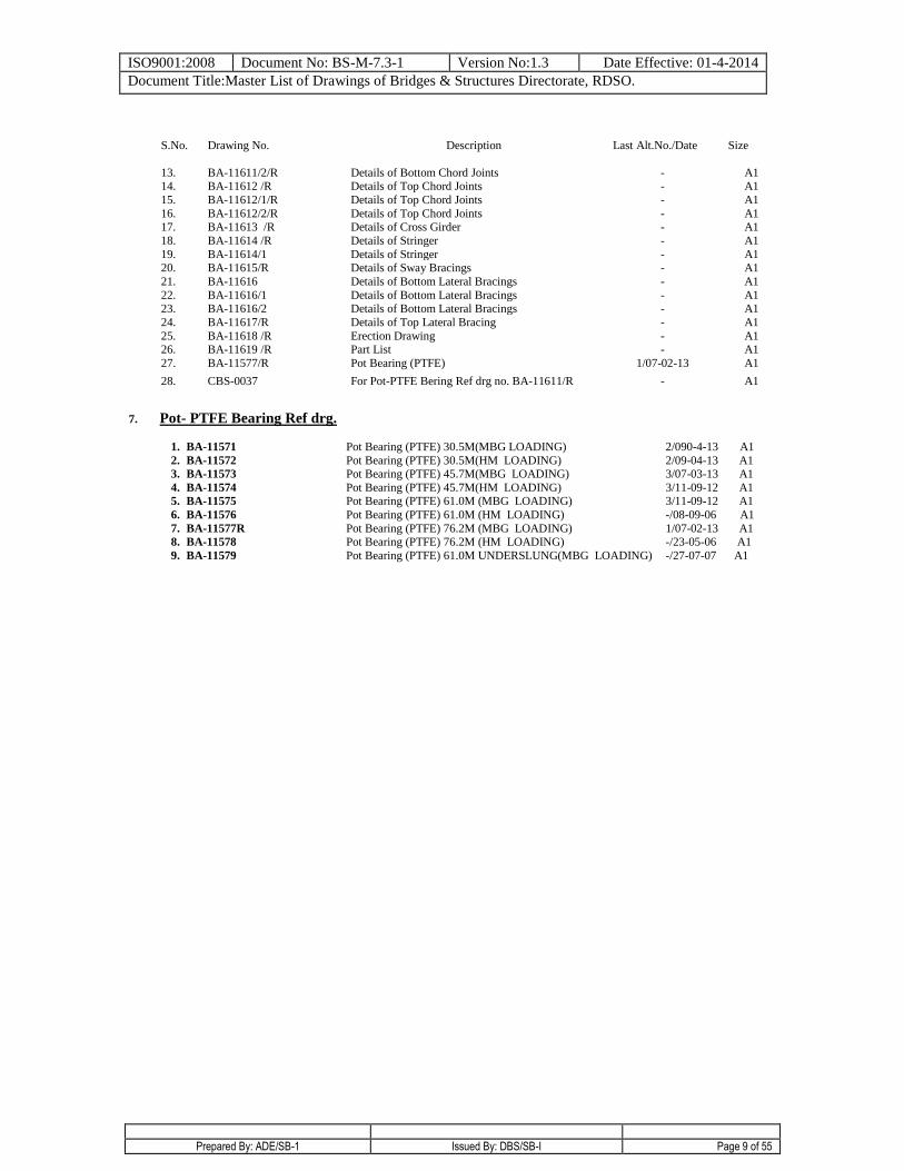
6. MBG Standard 76.2m Span
1. BA-11601/R General Arrangement - A1 2. BA-11602/R Stress Sheet - A1
3. BA-11603 Idealisation Diagram (not to be issued to railways) - A2
4. BA-11604/R Camber diagram - A1 5. BA-11605 Details of Bearings - A1
6. BA-11606/R Details of Bottom Chords - A1
7. BA-11607/R Details of Top Chords - A1 8. BA-11608/R Details of End Raker & Portal bracings - A1
9. BA-11609/R Details of Verticals - A1
10. BA-11610/R Details of Diagonals - A1 11. BA-11611/R Details of Bottom Chord Joints 1/07-02-13 A1
12. BA-11611/1/R Details of Bottom Chord Joints - A1
ISO9001:2008 Document No: BS-M-7.3-1 Version No:1.3 Date Effective: 01-4-2014
Document Title:Master List of Drawings of Bridges & Structures Directorate, RDSO.
Prepared By: ADE/SB-1 Issued By: DBS/SB-I Page 9 of 55
S.No. Drawing No.
Description Last Alt.No./Date Size
13. BA-11611/2/R Details of Bottom Chord Joints - A1 14. BA-11612 /R Details of Top Chord Joints - A1
15. BA-11612/1/R Details of Top Chord Joints - A1
16. BA-11612/2/R Details of Top Chord Joints - A1 17. BA-11613 /R Details of Cross Girder - A1
18. BA-11614 /R Details of Stringer - A1
19. BA-11614/1 Details of Stringer - A1 20. BA-11615/R Details of Sway Bracings - A1
21. BA-11616 Details of Bottom Lateral Bracings - A1
22. BA-11616/1 Details of Bottom Lateral Bracings - A1 23. BA-11616/2 Details of Bottom Lateral Bracings - A1
24. BA-11617/R Details of Top Lateral Bracing - A1
25. BA-11618 /R Erection Drawing - A1 26. BA-11619 /R Part List - A1
27. BA-11577/R Pot Bearing (PTFE) 1/07-02-13 A1
28. CBS-0037 For Pot-PTFE Bering Ref drg no. BA-11611/R - A1
7. Pot- PTFE Bearing Ref drg.
1. BA-11571 Pot Bearing (PTFE) 30.5M(MBG LOADING) 2/090-4-13 A1
2. BA-11572 Pot Bearing (PTFE) 30.5M(HM LOADING) 2/09-04-13 A1
3. BA-11573 Pot Bearing (PTFE) 45.7M(MBG LOADING) 3/07-03-13 A1
4. BA-11574 Pot Bearing (PTFE) 45.7M(HM LOADING) 3/11-09-12 A1
5. BA-11575 Pot Bearing (PTFE) 61.0M (MBG LOADING) 3/11-09-12 A1
6. BA-11576 Pot Bearing (PTFE) 61.0M (HM LOADING) -/08-09-06 A1
7. BA-11577R Pot Bearing (PTFE) 76.2M (MBG LOADING) 1/07-02-13 A1
8. BA-11578 Pot Bearing (PTFE) 76.2M (HM LOADING) -/23-05-06 A1
9. BA-11579 Pot Bearing (PTFE) 61.0M UNDERSLUNG(MBG LOADING) -/27-07-07 A1
ISO9001:2008 Document No: BS-M-7.3-1 Version No:1.3 Date Effective: 01-4-2014
Document Title:Master List of Drawings of Bridges & Structures Directorate, RDSO.
Prepared By: ADE/SB-1 Issued By: DBS/SB-I Page 10 of 55
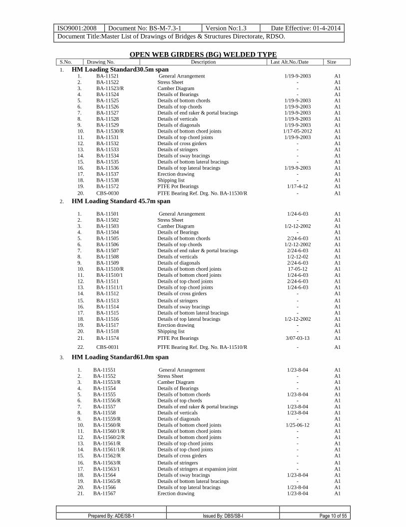
OPEN WEB GIRDERS (BG) WELDED TYPE
S.No. Drawing No. Description Last Alt.No./Date Size
1. HM Loading Standard30.5m span 1. BA-11521 General Arrangement 1/19-9-2003 A1
2. BA-11522 Stress Sheet - A1
3. BA-11523/R Camber Diagram - A1 4. BA-11524 Details of Bearings - A1
5. BA-11525 Details of bottom chords 1/19-9-2003 A1
6. BA-11526 Details of top chords 1/19-9-2003 A1 7. BA-11527 Details of end raker & portal bracings 1/19-9-2003 A1
8. BA-11528 Details of verticals 1/19-9-2003 A1
9. BA-11529 Details of diagonals 1/19-9-2003 A1 10. BA-11530/R Details of bottom chord joints 1/17-05-2012 A1
11. BA-11531 Details of top chord joints 1/19-9-2003 A1
12. BA-11532 Details of cross girders - A1 13. BA-11533 Details of stringers - A1
14. BA-11534 Details of sway bracings - A1
15. BA-11535 Details of bottom lateral bracings - A1
16. BA-11536 Details of top lateral bracings 1/19-9-2003 A1
17. BA-11537 Erection drawing - A1
18. BA-11538 Shipping list - A1 19. BA-11572 PTFE Pot Bearings 1/17-4-12 A1
20. CBS-0030 PTFE Bearing Ref. Drg. No. BA-11530/R - A1
2. HM Loading Standard 45.7m span
1. BA-11501 General Arrangement 1/24-6-03 A1
2. BA-11502 Stress Sheet - A1
3. BA-11503 Camber Diagram 1/2-12-2002 A1 4. BA-11504 Details of Bearings - A1
5. BA-11505 Details of bottom chords 2/24-6-03 A1
6. BA-11506 Details of top chords 1/2-12-2002 A1 7. BA-11507 Details of end raker & portal bracings 2/24-6-03 A1
8. BA-11508 Details of verticals 1/2-12-02 A1
9. BA-11509 Details of diagonals 2/24-6-03 A1 10. BA-11510/R Details of bottom chord joints 17-05-12 A1
11. BA-11510/1 Details of bottom chord joints 1/24-6-03 A1
12. BA-11511 Details of top chord joints 2/24-6-03 A1 13. BA-11511/1 Details of top chord joints 1/24-6-03 A1
14. BA-11512 Details of cross girders - A1
15. BA-11513 Details of stringers - A1 16. BA-11514 Details of sway bracings - A1
17. BA-11515 Details of bottom lateral bracings - A1
18. BA-11516 Details of top lateral bracings 1/2-12-2002 A1 19. BA-11517 Erection drawing - A1
20. BA-11518 Shipping list - A1
21. BA-11574 PTFE Pot Bearings 3/07-03-13 A1
22. CBS-0031 PTFE Bearing Ref. Drg. No. BA-11510/R - A1
3. HM Loading Standard61.0m span
1. BA-11551 General Arrangement 1/23-8-04 A1
2. BA-11552 Stress Sheet - A1 3. BA-11553/R Camber Diagram - A1
4. BA-11554 Details of Bearings - A1
5. BA-11555 Details of bottom chords 1/23-8-04 A1 6. BA-11556/R Details of top chords - A1
7. BA-11557 Details of end raker & portal bracings 1/23-8-04 A1 8. BA-11558 Details of verticals 1/23-8-04 A1
9. BA-11559/R Details of diagonals - A1
10. BA-11560/R Details of bottom chord joints 1/25-06-12 A1 11. BA-11560/1/R Details of bottom chord joints - A1
12. BA-11560/2/R Details of bottom chord joints - A1
13. BA-11561/R Details of top chord joints - A1 14. BA-11561/1/R Details of top chord joints - A1
15. BA-11562/R Details of cross girders - A1
16. BA-11563/R Details of stringers - A1
17. BA-11563/1 Details of stringers at expansion joint - A1 18. BA-11564 Details of sway bracings 1/23-8-04 A1
19. BA-11565/R Details of bottom lateral bracings - A1
20. BA-11566 Details of top lateral bracings 1/23-8-04 A1 21. BA-11567 Erection drawing 1/23-8-04 A1
ISO9001:2008 Document No: BS-M-7.3-1 Version No:1.3 Date Effective: 01-4-2014
Document Title:Master List of Drawings of Bridges & Structures Directorate, RDSO.
Prepared By: ADE/SB-1 Issued By: DBS/SB-I Page 11 of 55
S.N
o.
Drawing No. Description Last Alt.No./Date Size
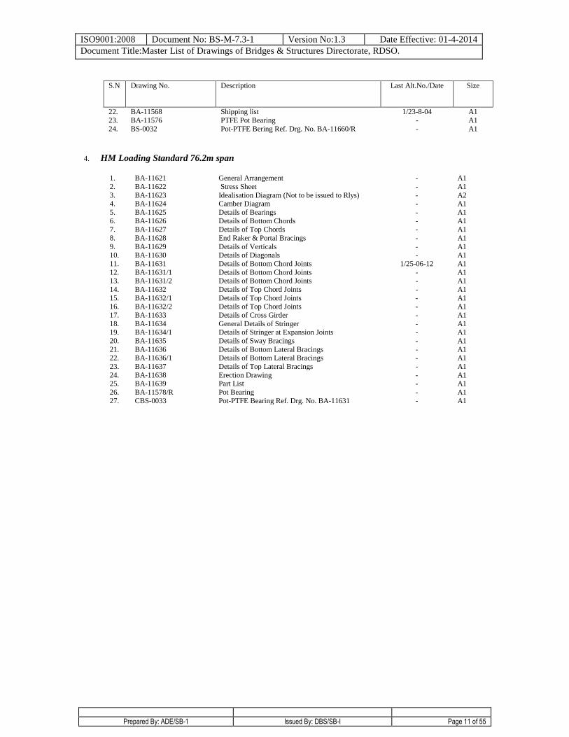
22. BA-11568 Shipping list 1/23-8-04 A1
23. BA-11576 PTFE Pot Bearing - A1
24. BS-0032 Pot-PTFE Bering Ref. Drg. No. BA-11660/R - A1
4. HM Loading Standard 76.2m span
1. BA-11621 General Arrangement - A1
2. BA-11622 Stress Sheet - A1
3. BA-11623 Idealisation Diagram (Not to be issued to Rlys) - A2 4. BA-11624 Camber Diagram - A1
5. BA-11625 Details of Bearings - A1
6. BA-11626 Details of Bottom Chords - A1 7. BA-11627 Details of Top Chords - A1
8. BA-11628 End Raker & Portal Bracings - A1
9. BA-11629 Details of Verticals - A1 10. BA-11630 Details of Diagonals - A1
11. BA-11631 Details of Bottom Chord Joints 1/25-06-12 A1
12. BA-11631/1 Details of Bottom Chord Joints - A1 13. BA-11631/2 Details of Bottom Chord Joints - A1
14. BA-11632 Details of Top Chord Joints - A1
15. BA-11632/1 Details of Top Chord Joints - A1 16. BA-11632/2 Details of Top Chord Joints - A1
17. BA-11633 Details of Cross Girder - A1
18. BA-11634 General Details of Stringer - A1 19. BA-11634/1 Details of Stringer at Expansion Joints - A1
20. BA-11635 Details of Sway Bracings - A1
21. BA-11636 Details of Bottom Lateral Bracings - A1 22. BA-11636/1 Details of Bottom Lateral Bracings - A1
23. BA-11637 Details of Top Lateral Bracings - A1
24. BA-11638 Erection Drawing - A1 25. BA-11639 Part List - A1
26. BA-11578/R Pot Bearing - A1
27. CBS-0033 Pot-PTFE Bearing Ref. Drg. No. BA-11631 - A1
ISO9001:2008 Document No: BS-M-7.3-1 Version No:1.3 Date Effective: 01-4-2014
Document Title:Master List of Drawings of Bridges & Structures Directorate, RDSO.
Prepared By: ADE/SB-1 Issued By: DBS/SB-I Page 12 of 55
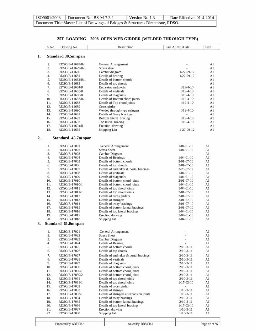
25T LOADING – 2008 OPEN WEB GIRDER (WELDED THROUGH TYPE)
S.No. Drawing No. Description Last Alt.No./Date Size
1. Standard 30.5m span
1. RDSO/B-11678/R/1 General Arrangement - A1 2. RDSO/B-11679/R/1 Stress sheet - A1
3. RDSO/B-11680 Camber diagram 1/27-09-12 A1
4. RDSO/B-11681 Details of bearing 1/27-09-12 A1 5. RDSO/B-11682/R/1 Details of bottom chords - A1
6. RDSO/B-11683 Details of top chords - A1 7. RDSO/B-11684/R End raker and portal 1/19-4-10 A1
8. RDSO/B-11685/R Details of verticals 1/19-4-10 A1
9. RDSO/B-11686/R Details of diagonals 1/19-4-10 A1 10. RDSO/B-11687/R/1 Details of Bottom chord joints 1/19-4-10 A1
11. RDSO/B-11688 Details of Top chord joints 1/19-4-10 A1
12. RDSO/B-11689 Cross girder - A1 13. RDSO/B-11690 Welded through type stringers 1/19-4-10 A1
14. RDSO/B-11691 Details of Sway bracings - A1
15. RDSO/B-11692 Bottom lateral bracing 1/19-4-10 A1 16. RDSO/B-11693 Top lateral bracing 1/19-4-10 A1
17. RDSO/B-11694/R Erection drawing - A1
18. RDSO/B-11695 Shipping List
1-27-09-12 A1
2. Standard 45.7m span
1. RDSO/B-17001 General Arrangement 1/04-01-10 A1 2. RDSO/B-17002 Stress Sheet 1/04-01-10 A1
3. RDSO/B-17003 Camber Diagram - A1
4. RDSO/B-17004 Details of Bearings 1/04-01-10 A1 5. RDSO/B-17005 Details of bottom chords 2/01-07-10 A1
6. RDSO/B-17006 Details of top chords 2/01-07-10 A1
7. RDSO/B-17007 Details of end raker & portal bracings 3/25-07-12 A1 8. RDSO/B-17008 Details of verticals 1/04-01-10 A1
9. RDSO/B-17009 Details of diagonals 1/04-01-10 A1 10. RDSO/B-17010 Details of bottom chord joints 2/01-07-10 A1
11. RDSO/B-17010/1 Details of bottom chord joints 1/04-01-10 A1
12. RDSO/B-17011 Details of top chord joints 1/04-01-10 A1 13. RDSO/B-17011/1 Details of top chord joints 2/01-07-10 A1
14. RDSO/B-17012 Details of cross girders 2/01-07-10 A1
15. RDSO/B-17013 Details of stringers 2/01-07-10 A1 16. RDSO/B-17014 Details of sway bracings 2/01-07-10 A1
17. RDSO/B-17015 Details of bottom lateral bracings 2/01-07-10 A1
18. RDSO/B-17016 Details of top lateral bracings 1/04-01-10 A1 19. RDSO/B-17017 Erection drawing 1/04-01-10 A1
20. RDSO/B-17018 Shipping list 1/04-01-10 A1
3. Standard 61.0m span
1. RDSO/B-17021 General Arrangement - A1
2. RDSO/B-17022 Stress Sheet - A1
3. RDSO/B-17023 Camber Diagram - A1 4. RDSO/B-17024 Details of Bearing - A1
5. RDSO/B-17025 Details of bottom chords 2/10-3-11 A1
6. RDSO/B-17026 Details of top chords 2/10-3-11 A1
7. RDSO/B-17027 Details of end raker & portal bracings 2/10-3-11 A1
8. RDSO/B-17028 Details of verticals 2/10-3-11 A1
9. RDSO/B-17029 Details of diagonals 2/10-3-11 A1 10. RDSO/B-17030 Details of bottom chord joints 2/10-3-11 A1
11. RDSO/B-17030/1 Details of bottom chord joints 2/10-3-11 A1
12. RDSO/B-17030/2 Details of bottom chord joints 2/10-3-11 A1 13. RDSO/B-17031 Details of top chord joints 2/10-3-11 A1
14. RDSO/B-17031/1 Details of top chord joints 1/17-03-10 A1
15. RDSO/B-17032 Details of cross girder - A1 16. RDSO/B-17033 Details of stringer 1/10-3-11 A1
17. RDSO/B-17033/1 Details of stringers at expansion joints 1/10-3-11 A1
18. RDSO/B-17034 Details of sway bracings 2/10-3-11 A1 19. RDSO/B-17035 Details of bottom lateral bracings 2/10-3-11 A1
20. RDSO/B-17036 Details of top lateral bracings 1/17-03-10 A1
21. RDSO/B-17037 Erection drawing 1/10-3-11 A1 22. RDSO/B-17038 Shipping list 1/10-3-11 A1
ISO9001:2008 Document No: BS-M-7.3-1 Version No:1.3 Date Effective: 01-4-2014
Document Title:Master List of Drawings of Bridges & Structures Directorate, RDSO.
Prepared By: ADE/SB-1 Issued By: DBS/SB-I Page 13 of 55
S.No. Drawing No. Description Last Alt.No./Date Size
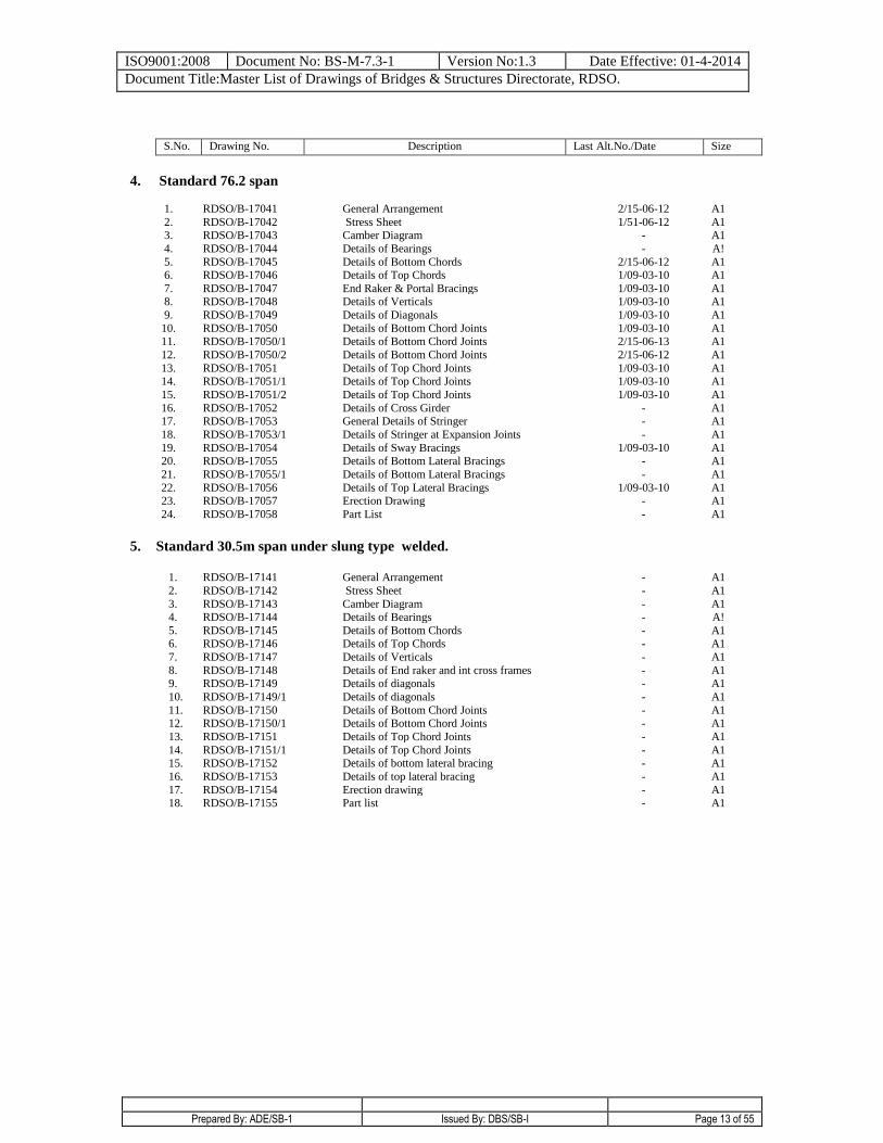
4. Standard 76.2 span
1. RDSO/B-17041 General Arrangement 2/15-06-12 A1
2. RDSO/B-17042 Stress Sheet 1/51-06-12 A1 3. RDSO/B-17043 Camber Diagram - A1
4. RDSO/B-17044 Details of Bearings - A!
5. RDSO/B-17045 Details of Bottom Chords 2/15-06-12 A1 6. RDSO/B-17046 Details of Top Chords 1/09-03-10 A1
7. RDSO/B-17047 End Raker & Portal Bracings 1/09-03-10 A1 8. RDSO/B-17048 Details of Verticals 1/09-03-10 A1
9. RDSO/B-17049 Details of Diagonals 1/09-03-10 A1
10. RDSO/B-17050 Details of Bottom Chord Joints 1/09-03-10 A1 11. RDSO/B-17050/1 Details of Bottom Chord Joints 2/15-06-13 A1
12. RDSO/B-17050/2 Details of Bottom Chord Joints 2/15-06-12 A1
13. RDSO/B-17051 Details of Top Chord Joints 1/09-03-10 A1 14. RDSO/B-17051/1 Details of Top Chord Joints 1/09-03-10 A1
15. RDSO/B-17051/2 Details of Top Chord Joints 1/09-03-10 A1
16. RDSO/B-17052 Details of Cross Girder - A1 17. RDSO/B-17053 General Details of Stringer - A1
18. RDSO/B-17053/1 Details of Stringer at Expansion Joints - A1
19. RDSO/B-17054 Details of Sway Bracings 1/09-03-10 A1 20. RDSO/B-17055 Details of Bottom Lateral Bracings - A1
21. RDSO/B-17055/1 Details of Bottom Lateral Bracings - A1
22. RDSO/B-17056 Details of Top Lateral Bracings 1/09-03-10 A1 23. RDSO/B-17057 Erection Drawing - A1
24. RDSO/B-17058 Part List - A1
5. Standard 30.5m span under slung type welded.
1. RDSO/B-17141 General Arrangement - A1
2. RDSO/B-17142 Stress Sheet - A1
3. RDSO/B-17143 Camber Diagram - A1 4. RDSO/B-17144 Details of Bearings - A!
5. RDSO/B-17145 Details of Bottom Chords - A1 6. RDSO/B-17146 Details of Top Chords - A1
7. RDSO/B-17147 Details of Verticals - A1
8. RDSO/B-17148 Details of End raker and int cross frames - A1 9. RDSO/B-17149 Details of diagonals - A1
10. RDSO/B-17149/1 Details of diagonals - A1
11. RDSO/B-17150 Details of Bottom Chord Joints - A1 12. RDSO/B-17150/1 Details of Bottom Chord Joints - A1
13. RDSO/B-17151 Details of Top Chord Joints - A1
14. RDSO/B-17151/1 Details of Top Chord Joints - A1 15. RDSO/B-17152 Details of bottom lateral bracing - A1
16. RDSO/B-17153 Details of top lateral bracing - A1
17. RDSO/B-17154 Erection drawing - A1 18. RDSO/B-17155 Part list - A1
ISO9001:2008 Document No: BS-M-7.3-1 Version No:1.3 Date Effective: 01-4-2014
Document Title:Master List of Drawings of Bridges & Structures Directorate, RDSO.
Prepared By: ADE/SB-1 Issued By: DBS/SB-I Page 14 of 55
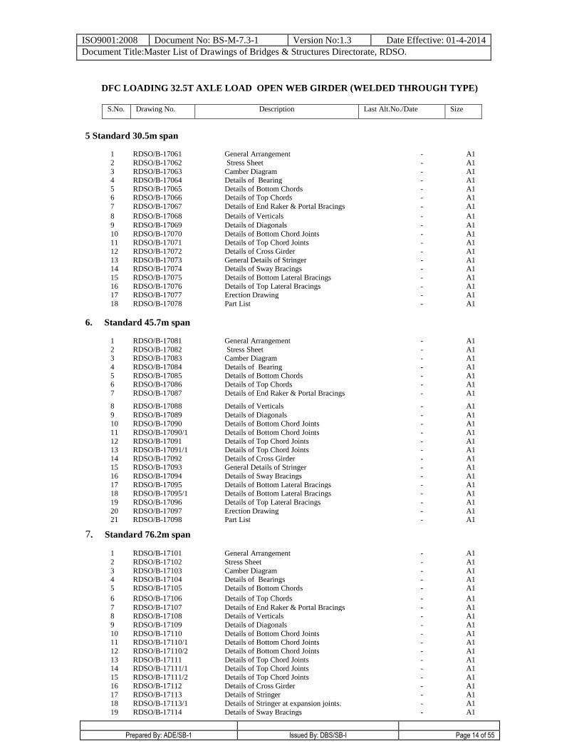
DFC LOADING 32.5T AXLE LOAD OPEN WEB GIRDER (WELDED THROUGH TYPE)
S.No. Drawing No. Description Last Alt.No./Date Size
5 Standard 30.5m span
1 RDSO/B-17061 General Arrangement - A1
2 RDSO/B-17062 Stress Sheet - A1
3 RDSO/B-17063 Camber Diagram - A1 4 RDSO/B-17064 Details of Bearing - A1
5 RDSO/B-17065 Details of Bottom Chords - A1 6 RDSO/B-17066 Details of Top Chords - A1
7 RDSO/B-17067 Details of End Raker & Portal Bracings - A1
8 RDSO/B-17068 Details of Verticals - A1
9 RDSO/B-17069 Details of Diagonals - A1
10 RDSO/B-17070 Details of Bottom Chord Joints - A1
11 RDSO/B-17071 Details of Top Chord Joints - A1
12 RDSO/B-17072 Details of Cross Girder - A1
13 RDSO/B-17073 General Details of Stringer - A1 14 RDSO/B-17074 Details of Sway Bracings - A1
15 RDSO/B-17075 Details of Bottom Lateral Bracings - A1
16 RDSO/B-17076 Details of Top Lateral Bracings - A1 17 RDSO/B-17077 Erection Drawing - A1
18 RDSO/B-17078 Part List - A1
6. Standard 45.7m span
1 RDSO/B-17081 General Arrangement - A1
2 RDSO/B-17082 Stress Sheet - A1 3 RDSO/B-17083 Camber Diagram - A1
4 RDSO/B-17084 Details of Bearing - A1
5 RDSO/B-17085 Details of Bottom Chords - A1 6 RDSO/B-17086 Details of Top Chords - A1
7 RDSO/B-17087 Details of End Raker & Portal Bracings - A1
8 RDSO/B-17088 Details of Verticals - A1
9 RDSO/B-17089 Details of Diagonals - A1 10 RDSO/B-17090 Details of Bottom Chord Joints - A1
11 RDSO/B-17090/1 Details of Bottom Chord Joints - A1
12 RDSO/B-17091 Details of Top Chord Joints - A1 13 RDSO/B-17091/1 Details of Top Chord Joints - A1
14 RDSO/B-17092 Details of Cross Girder - A1 15 RDSO/B-17093 General Details of Stringer - A1
16 RDSO/B-17094 Details of Sway Bracings - A1
17 RDSO/B-17095 Details of Bottom Lateral Bracings - A1 18 RDSO/B-17095/1 Details of Bottom Lateral Bracings - A1
19 RDSO/B-17096 Details of Top Lateral Bracings - A1
20 RDSO/B-17097 Erection Drawing - A1 21 RDSO/B-17098 Part List - A1
7. Standard 76.2m span
1 RDSO/B-17101 General Arrangement - A1
2 RDSO/B-17102 Stress Sheet - A1
3 RDSO/B-17103 Camber Diagram - A1 4 RDSO/B-17104 Details of Bearings - A1
5 RDSO/B-17105 Details of Bottom Chords - A1
6 RDSO/B-17106 Details of Top Chords - A1
7 RDSO/B-17107 Details of End Raker & Portal Bracings - A1 8 RDSO/B-17108 Details of Verticals - A1
9 RDSO/B-17109 Details of Diagonals - A1
10 RDSO/B-17110 Details of Bottom Chord Joints - A1 11 RDSO/B-17110/1 Details of Bottom Chord Joints - A1
12 RDSO/B-17110/2 Details of Bottom Chord Joints - A1
13 RDSO/B-17111 Details of Top Chord Joints - A1 14 RDSO/B-17111/1 Details of Top Chord Joints - A1
15 RDSO/B-17111/2 Details of Top Chord Joints - A1
16 RDSO/B-17112 Details of Cross Girder - A1 17 RDSO/B-17113 Details of Stringer - A1
18 RDSO/B-17113/1 Details of Stringer at expansion joints. - A1
19 RDSO/B-17114 Details of Sway Bracings - A1
ISO9001:2008 Document No: BS-M-7.3-1 Version No:1.3 Date Effective: 01-4-2014
Document Title:Master List of Drawings of Bridges & Structures Directorate, RDSO.
Prepared By: ADE/SB-1 Issued By: DBS/SB-I Page 15 of 55
20 RDSO/B-17115 Details of Bottom Lateral Bracings - A1
21 RDSO/B-17115/1 Details of Bottom Lateral Bracings - A1
22 RDSO/B-17116 Details of Top Lateral Bracings - A1
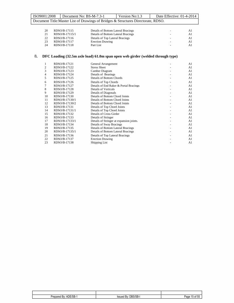
23 RDSO/B-17117 Erection Drawing - A1 24 RDSO/B-17118 Part List - A1
8. DFC Loading (32.5m axle load) 61.0m span open web girder (welded through type)
1 RDSO/B-17121 General Arrangement - A1
2 RDSO/B-17122 Stress Sheet - A1
3 RDSO/B-17123 Camber Diagram - A1 4 RDSO/B-17124 Details of Bearings - A1
5 RDSO/B-17125 Details of Bottom Chords - A1
6 RDSO/B-17126 Details of Top Chords - A1
7 RDSO/B-17127 Details of End Raker & Portal Bracings - A1 8 RDSO/B-17128 Details of Verticals - A1
9 RDSO/B-17129 Details of Diagonals - A1
10 RDSO/B-17130 Details of Bottom Chord Joints - A1 11 RDSO/B-17130/1 Details of Bottom Chord Joints - A1
12 RDSO/B-17130/2 Details of Bottom Chord Joints - A1
13 RDSO/B-17131 Details of Top Chord Joints - A1 14 RDSO/B-17131/1 Details of Top Chord Joints - A1
15 RDSO/B-17132 Details of Cross Girder - A1
16 RDSO/B-17133 Details of Stringer - A1 17 RDSO/B-17133/1 Details of Stringer at expansion joints. - A1
18 RDSO/B-17134 Details of Sway Bracings - A1
19 RDSO/B-17135 Details of Bottom Lateral Bracings - A1 20 RDSO/B-17135/1 Details of Bottom Lateral Bracings - A1
21 RDSO/B-17136 Details of Top Lateral Bracings - A1 22 RDSO/B-17137 Erection Drawing - A1
23 RDSO/B-17138 Shipping List - A1
ISO9001:2008 Document No: BS-M-7.3-1 Version No:1.3 Date Effective: 01-4-2014
Document Title:Master List of Drawings of Bridges & Structures Directorate, RDSO.
Prepared By: ADE/SB-1 Issued By: DBS/SB-I Page 16 of 55
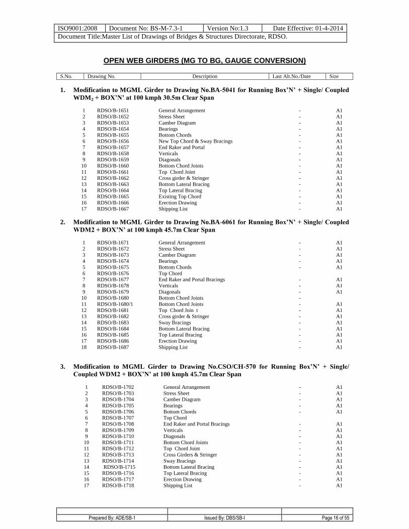
OPEN WEB GIRDERS (MG TO BG, GAUGE CONVERSION)
S.No. Drawing No. Description Last Alt.No./Date Size
1. Modification to MGML Girder to Drawing No.BA-5041 for Running Box’N’ + Single/ Coupled
WDM2 + BOX’N’ at 100 kmph 30.5m Clear Span
1 RDSO/B-1651 General Arrangement - A1
2 RDSO/B-1652 Stress Sheet - A1
3 RDSO/B-1653 Camber Diagram - A1 4 RDSO/B-1654 Bearings - A1
5 RDSO/B-1655 Bottom Chords - A1 6 RDSO/B-1656 New Top Chord & Sway Bracings - A1
7 RDSO/B-1657 End Raker and Portal - A1
8 RDSO/B-1658 Verticals - A1 9 RDSO/B-1659 Diagonals - A1
10 RDSO/B-1660 Bottom Chord Joints - A1
11 RDSO/B-1661 Top Chord Joint - A1 12 RDSO/B-1662 Cross girder & Stringer - A1
13 RDSO/B-1663 Bottom Lateral Bracing - A1
14 RDSO/B-1664 Top Lateral Bracing - A1 15 RDSO/B-1665 Existing Top Chord - A1
16 RDSO/B-1666 Erection Drawing - A1
17 RDSO/B-1667 Shipping List - A1
2. Modification to MGML Girder to Drawing No.BA-6061 for Running Box’N’ + Single/ Coupled
WDM2 + BOX’N’ at 100 kmph 45.7m Clear Span
1 RDSO/B-1671 General Arrangement - A1
2 RDSO/B-1672 Stress Sheet - A1
3 RDSO/B-1673 Camber Diagram - A1 4 RDSO/B-1674 Bearings - A1
5 RDSO/B-1675 Bottom Chords - A1
6 RDSO/B-1676 Top Chord
7 RDSO/B-1677 End Raker and Portal Bracings - A1
8 RDSO/B-1678 Verticals - A1
9 RDSO/B-1679 Diagonals - A1 10 RDSO/B-1680 Bottom Chord Joints -
11 RDSO/B-1680/1 Bottom Chord Joints - A1
12 RDSO/B-1681 Top Chord Join t - A1 13 RDSO/B-1682 Cross girder & Stringer - A1
14 RDSO/B-1683 Sway Bracings - A1
15 RDSO/B-1684 Bottom Lateral Bracing - A1 16 RDSO/B-1685 Top Lateral Bracing - A1
17 RDSO/B-1686 Erection Drawing - A1
18 RDSO/B-1687 Shipping List
- A1
3. Modification to MGML Girder to Drawing No.CSO/CH-570 for Running Box’N’ + Single/
Coupled WDM2 + BOX’N’ at 100 kmph 45.7m Clear Span
1 RDSO/B-1702 General Arrangement - A1
2 RDSO/B-1703 Stress Sheet - A1 3 RDSO/B-1704 Camber Diagram - A1
4 RDSO/B-1705 Bearings - A1
5 RDSO/B-1706 Bottom Chords - A1 6 RDSO/B-1707 Top Chord
7 RDSO/B-1708 End Raker and Portal Bracings - A1
8 RDSO/B-1709 Verticals - A1 9 RDSO/B-1710 Diagonals - A1
10 RDSO/B-1711 Bottom Chord Joints - A1 11 RDSO/B-1712 Top Chord Joint - A1
12 RDSO/B-1713 Cross Girders & Stringer - A1
13 RDSO/B-1714 Sway Bracings - A1 14 RDSO/B-1715 Bottom Lateral Bracing - A1
15 RDSO/B-1716 Top Lateral Bracing - A1
16 RDSO/B-1717 Erection Drawing - A1 17 RDSO/B-1718 Shipping List - A1
ISO9001:2008 Document No: BS-M-7.3-1 Version No:1.3 Date Effective: 01-4-2014
Document Title:Master List of Drawings of Bridges & Structures Directorate, RDSO.
Prepared By: ADE/SB-1 Issued By: DBS/SB-I Page 17 of 55
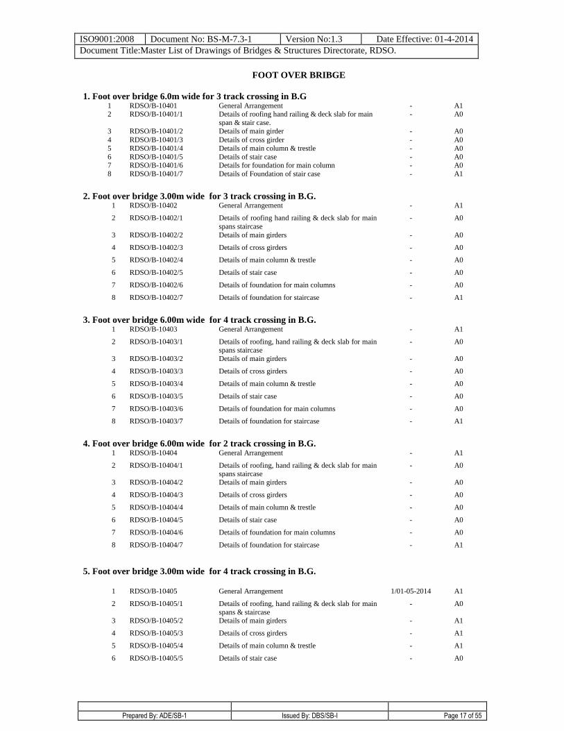
FOOT OVER BRIBGE
1. Foot over bridge 6.0m wide for 3 track crossing in B.G 1 RDSO/B-10401 General Arrangement - A1 2 RDSO/B-10401/1 Details of roofing hand railing & deck slab for main
span & stair case.
- A0
3 RDSO/B-10401/2 Details of main girder - A0
4 RDSO/B-10401/3 Details of cross girder - A0
5 RDSO/B-10401/4 Details of main column & trestle - A0
6 RDSO/B-10401/5 Details of stair case - A0 7 RDSO/B-10401/6 Details for foundation for main column - A0
8 RDSO/B-10401/7 Details of Foundation of stair case - A1
2. Foot over bridge 3.00m wide for 3 track crossing in B.G. 1 RDSO/B-10402 General Arrangement - A1
2 RDSO/B-10402/1 Details of roofing hand railing & deck slab for main
spans staircase
- A0
3 RDSO/B-10402/2 Details of main girders - A0
4 RDSO/B-10402/3 Details of cross girders - A0
5 RDSO/B-10402/4 Details of main column & trestle - A0
6 RDSO/B-10402/5 Details of stair case - A0
7 RDSO/B-10402/6 Details of foundation for main columns - A0
8 RDSO/B-10402/7 Details of foundation for staircase - A1
3. Foot over bridge 6.00m wide for 4 track crossing in B.G. 1 RDSO/B-10403 General Arrangement - A1
2 RDSO/B-10403/1 Details of roofing, hand railing & deck slab for main spans staircase
- A0
3 RDSO/B-10403/2 Details of main girders - A0
4 RDSO/B-10403/3 Details of cross girders - A0
5 RDSO/B-10403/4 Details of main column & trestle - A0
6 RDSO/B-10403/5 Details of stair case - A0
7 RDSO/B-10403/6 Details of foundation for main columns - A0
8 RDSO/B-10403/7 Details of foundation for staircase - A1
4. Foot over bridge 6.00m wide for 2 track crossing in B.G. 1 RDSO/B-10404 General Arrangement - A1
2 RDSO/B-10404/1 Details of roofing, hand railing & deck slab for main spans staircase
- A0
3 RDSO/B-10404/2 Details of main girders - A0
4 RDSO/B-10404/3 Details of cross girders - A0
5 RDSO/B-10404/4 Details of main column & trestle - A0
6 RDSO/B-10404/5 Details of stair case - A0
7 RDSO/B-10404/6 Details of foundation for main columns - A0
8 RDSO/B-10404/7 Details of foundation for staircase - A1
5. Foot over bridge 3.00m wide for 4 track crossing in B.G.
1 RDSO/B-10405 General Arrangement 1/01-05-2014 A1
2 RDSO/B-10405/1 Details of roofing, hand railing & deck slab for main
spans & staircase
- A0
3 RDSO/B-10405/2 Details of main girders - A1
4 RDSO/B-10405/3 Details of cross girders - A1
5 RDSO/B-10405/4 Details of main column & trestle - A1
6 RDSO/B-10405/5 Details of stair case - A0
ISO9001:2008 Document No: BS-M-7.3-1 Version No:1.3 Date Effective: 01-4-2014
Document Title:Master List of Drawings of Bridges & Structures Directorate, RDSO.
Prepared By: ADE/SB-1 Issued By: DBS/SB-I Page 18 of 55
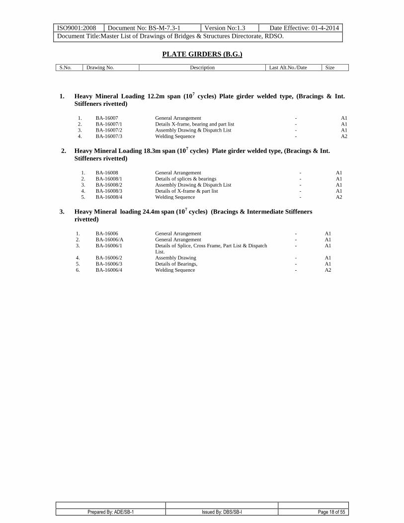
PLATE GIRDERS (B.G.)
S.No. Drawing No. Description Last Alt.No./Date Size
1. Heavy Mineral Loading 12.2m span (107 cycles) Plate girder welded type, (Bracings & Int.
Stiffeners rivetted)
1. BA-16007 General Arrangement - A1
2. BA-16007/1 Details X-frame, bearing and part list - A1 3. BA-16007/2 Assembly Drawing & Dispatch List - A1
4. BA-16007/3 Welding Sequence - A2
2. Heavy Mineral Loading 18.3m span (107 cycles) Plate girder welded type, (Bracings & Int.
Stiffeners rivetted)
1. BA-16008 General Arrangement - A1
2. BA-16008/1 Details of splices & bearings - A1 3. BA-16008/2 Assembly Drawing & Dispatch List - A1
4. BA-16008/3 Details of X-frame & part list - A1
5. BA-16008/4 Welding Sequence - A2
3. Heavy Mineral loading 24.4m span (107 cycles) (Bracings & Intermediate Stiffeners
rivetted)
1. BA-16006 General Arrangement - A1 2. BA-16006/A General Arrangement - A1
3. BA-16006/1 Details of Splice, Cross Frame, Part List & Dispatch
List.
- A1
4. BA-16006/2 Assembly Drawing - A1
5. BA-16006/3 Details of Bearings, - A1
6. BA-16006/4 Welding Sequence - A2
ISO9001:2008 Document No: BS-M-7.3-1 Version No:1.3 Date Effective: 01-4-2014
Document Title:Master List of Drawings of Bridges & Structures Directorate, RDSO.
Prepared By: ADE/SB-1 Issued By: DBS/SB-I Page 19 of 55
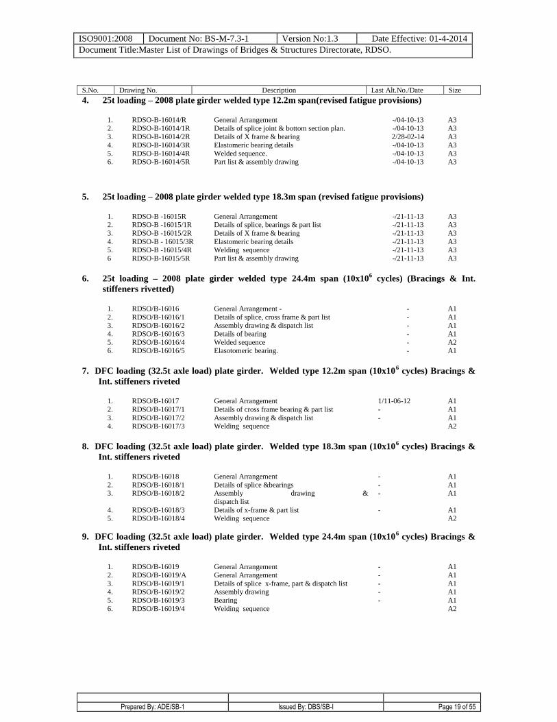
S.No. Drawing No. Description Last Alt.No./Date Size
4. 25t loading – 2008 plate girder welded type 12.2m span(revised fatigue provisions)
1. RDSO-B-16014/R General Arrangement -/04-10-13 A3
2. RDSO-B-16014/1R Details of splice joint & bottom section plan. -/04-10-13 A3 3. RDSO-B-16014/2R Details of X frame & bearing 2/28-02-14 A3
4. RDSO-B-16014/3R Elastomeric bearing details -/04-10-13 A3
5. 6.
RDSO-B-16014/4R RDSO-B-16014/5R
Welded sequence. Part list & assembly drawing
-/04-10-13 -/04-10-13
A3 A3
5. 25t loading – 2008 plate girder welded type 18.3m span (revised fatigue provisions)
1. RDSO-B -16015R General Arrangement -/21-11-13 A3 2. RDSO-B -16015/1R Details of splice, bearings & part list -/21-11-13 A3
3. RDSO-B -16015/2R Details of X frame & bearing -/21-11-13 A3
4. RDSO-B - 16015/3R Elastomeric bearing details -/21-11-13 A3 5. RDSO-B -16015/4R Welding sequence -/21-11-13 A3
6 RDSO-B-16015/5R Part list & assembly drawing -/21-11-13 A3
6. 25t loading – 2008 plate girder welded type 24.4m span (10x106 cycles) (Bracings & Int.
stiffeners rivetted)
1. RDSO/B-16016 General Arrangement - - A1
2. RDSO/B-16016/1 Details of splice, cross frame & part list - A1 3. RDSO/B-16016/2 Assembly drawing & dispatch list - A1
4. RDSO/B-16016/3 Details of bearing - A1
5. RDSO/B-16016/4 Welded sequence - A2 6. RDSO/B-16016/5 Elasotomeric bearing. - A1
7. DFC loading (32.5t axle load) plate girder. Welded type 12.2m span (10x106 cycles) Bracings &
Int. stiffeners riveted
1. RDSO/B-16017 General Arrangement 1/11-06-12 A1
2. RDSO/B-16017/1 Details of cross frame bearing & part list - A1
3. RDSO/B-16017/2 Assembly drawing & dispatch list - A1 4. RDSO/B-16017/3 Welding sequence A2
8. DFC loading (32.5t axle load) plate girder. Welded type 18.3m span (10x106 cycles) Bracings &
Int. stiffeners riveted
1. RDSO/B-16018 General Arrangement - A1
2. RDSO/B-16018/1 Details of splice &bearings - A1 3. RDSO/B-16018/2 Assembly drawing &
dispatch list
- A1
4. RDSO/B-16018/3 Details of x-frame & part list - A1 5. RDSO/B-16018/4 Welding sequence A2
9. DFC loading (32.5t axle load) plate girder. Welded type 24.4m span (10x106 cycles) Bracings &
Int. stiffeners riveted
1. RDSO/B-16019 General Arrangement - A1
2. RDSO/B-16019/A General Arrangement - A1
3. RDSO/B-16019/1 Details of splice x-frame, part & dispatch list - A1 4. RDSO/B-16019/2 Assembly drawing - A1
5. RDSO/B-16019/3 Bearing - A1
6. RDSO/B-16019/4 Welding sequence A2
ISO9001:2008 Document No: BS-M-7.3-1 Version No:1.3 Date Effective: 01-4-2014
Document Title:Master List of Drawings of Bridges & Structures Directorate, RDSO.
Prepared By: ADE/SB-1 Issued By: DBS/SB-I Page 20 of 55
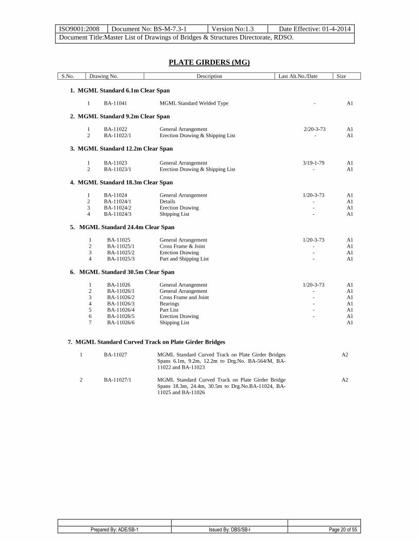
PLATE GIRDERS (MG)
S.No. Drawing No. Description Last Alt.No./Date Size
1. MGML Standard 6.1m Clear Span
1 BA-11041 MGML Standard Welded Type - A1
2. MGML Standard 9.2m Clear Span
1 BA-11022 General Arrangement 2/20-3-73 A1
2 BA-11022/1 Erection Drawing & Shipping List
- A1
3. MGML Standard 12.2m Clear Span
1 BA-11023 General Arrangement 3/19-1-79 A1
2 BA-11023/1 Erection Drawing & Shipping List
- A1
4. MGML Standard 18.3m Clear Span
1 BA-11024 General Arrangement 1/20-3-73 A1
2 BA-11024/1 Details - A1 3 BA-11024/2 Erection Drawing - A1
4 BA-11024/3 Shipping List - A1
5. MGML Standard 24.4m Clear Span 1
BA-11025
General Arrangement
1/20-3-73
A1
2 BA-11025/1 Cross Frame & Joint - A1
3 BA-11025/2 Erection Drawing - A1 4 BA-11025/3 Part and Shipping List
- A1
6. MGML Standard 30.5m Clear Span
1
BA-11026
General Arrangement
1/20-3-73
A1 2 BA-11026/1 General Arrangement - A1
3 BA-11026/2 Cross Frame and Joint - A1
4 BA-11026/3 Bearings - A1 5 BA-11026/4 Part List - A1
6 BA-11026/5 Erection Drawing - A1
7 BA-11026/6
Shipping List A1
7. MGML Standard Curved Track on Plate Girder Bridges
1 BA-11027 MGML Standard Curved Track on Plate Girder Bridges
Spans 6.1m, 9.2m, 12.2m to Drg.No. BA-564/M, BA-
11022 and BA-11023
A2
2 BA-11027/1 MGML Standard Curved Track on Plate Girder Bridge
Spans 18.3m, 24.4m, 30.5m to Drg.No.BA-11024, BA-11025 and BA-11026
A2
ISO9001:2008 Document No: BS-M-7.3-1 Version No:1.3 Date Effective: 01-4-2014
Document Title:Master List of Drawings of Bridges & Structures Directorate, RDSO.
Prepared By: ADE/SB-1 Issued By: DBS/SB-I Page 21 of 55
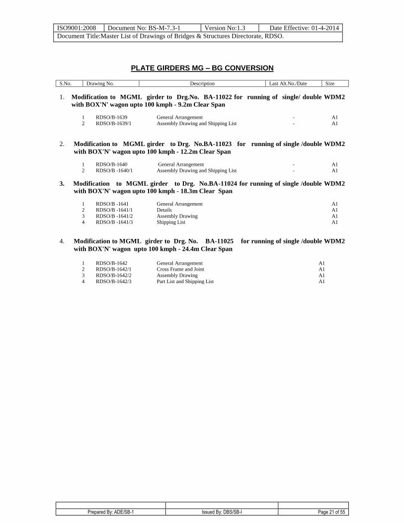
PLATE GIRDERS MG – BG CONVERSION
S.No. Drawing No. Description Last Alt.No./Date Size
1. Modification to MGML girder to Drg.No. BA-11022 for running of single/ double WDM2
with BOX'N' wagon upto 100 kmph - 9.2m Clear Span
1 RDSO/B-1639 General Arrangement - A1
2 RDSO/B-1639/1 Assembly Drawing and Shipping List
- A1
2. Modification to MGML girder to Drg. No.BA-11023 for running of single /double WDM2
with BOX'N' wagon upto 100 kmph - 12.2m Clear Span
1 RDSO/B-1640 General Arrangement - A1
2 RDSO/B -1640/1 Assembly Drawing and Shipping List - A1
3. Modification to MGML girder to Drg. No.BA-11024 for running of single /double WDM2
with BOX'N' wagon upto 100 kmph - 18.3m Clear Span
1 RDSO/B -1641 General Arrangement A1
2 RDSO/B -1641/1 Details A1
3 RDSO/B -1641/2 Assembly Drawing A1 4 RDSO/B -1641/3 Shipping List
A1
4. Modification to MGML girder to Drg. No. BA-11025 for running of single /double WDM2
with BOX'N' wagon upto 100 kmph - 24.4m Clear Span
1 RDSO/B-1642 General Arrangement A1 2 RDSO/B-1642/1 Cross Frame and Joint A1
3 RDSO/B-1642/2 Assembly Drawing A1
4 RDSO/B-1642/3 Part List and Shipping List A1
ISO9001:2008 Document No: BS-M-7.3-1 Version No:1.3 Date Effective: 01-4-2014
Document Title:Master List of Drawings of Bridges & Structures Directorate, RDSO.
Prepared By: ADE/SB-1 Issued By: DBS/SB-I Page 22 of 55
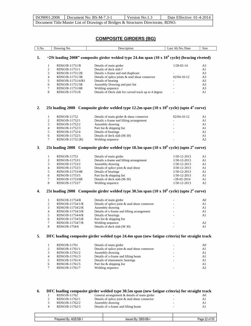
COMPOSITE GIRDERS (BG)
S.No. Drawing No. Description Last Alt.No./Date Size
1. “25t loading 2008” composite girder welded type 24.4m span (10 x 106 cycle) (bracing riveted)
1 RDSO/B-11751/R Details of main girder 1/28-02-14 A3 2 RDSO/B-11751/1 Details of deck slab f A1
3 RDSO/B-11751/2R Details x-frame and end diaphram - A3
4 RDSO/B-11751/3R Details of splice joints & stud shear connector 02/04-10-12 A3 5 RDSO/B-11751/4/R1 Details of bearing - A3
6 RDSO/B-11751/5R Assembly Drawing and part list - A3 7 RDSO/B-11751/6R Welding sequence - A3
8 RDSO/B-11751/8 Details of Deck slab for curved track up to 4 degree - A1
2. 25t loading 2008 Composite girder welded type 12.2m span (10 x 106 cycle) (upto 4
o curve)
1 RDSO/B-11752 Details of main girder & shear connector 02/04-10-12 A1
2 RDSO/B-11752/1 Details x-frame and lifting arrangement - A1
3 RDSO/B-11752/2 Assembly drawing - A1 4 RDSO/B-11752/3 Part list & shipping list - A1
5 RDSO/B-11752/4 Details of bearings - A1
6 RDSO/B-11752/5 Details of deck slab (M-30) A1 7 RDSO/B-11752 (R) Welding sequence - A2
3. 25t loading 2008 Composite girder welded type 18.3m span (10 x 106 cycle) (upto 2
o curve)
1 RDSO/B-11753 Details of main girder 1/30-12-2013 A1
2 RDSO/B-11753/1 Details x-frame and lifting arrangement 1/30-12-2013 A1
3 RDSO/B-11753/2 Assembly drawing 1/30-12-2013 A1 4 RDSO/B-11753/3 Details of splice joint & stud shear 3/30-12-2013 A1
5 RDSO/B-11753/4R Details of bearings 1/30-12-2013 A1
6 RDSO/B-11753/5 Part list & shipping list 1/30-12-2013 A1 7 RDSO/B-11753/6R Details of deck slab (M-30) -/28-02-2014 A1
8 RDSO/B-11753/7 Welding sequence 1/30-12-2013 A2
4. 25t loading 2008 Composite girder welded type 30.5m span (10 x 106 cycle) (upto 2
o curve)
1 RDSO/B-11754/R Details of main girder - A0
2 RDSO/B-11754/1/R Details of splice joint & stud shear connector - A1 3 RDSO/B-11754/2/R Assembly drawing - A1
4 RDSO/B-11754/3/R Details of x-frame and lifting arrangement - A1
5 RDSO/B-11754/4/R Details of bearings - A1 6 RDSO/B-11754/5/R Part list & shipping list
7 RDSO/B-11754/7/R Welding sequence - A2
8 RDSO/B-1754/6 Details of deck slab (M 30) - A1
5. DFC loading composite girder welded type 24.4m span (new fatigue criteria) for straight track
1 RDSO/B-11761 Details of main girder - A0
2 RDSO/B-11761/1 Details of splice joint & stud shear connector - A1
3 RDSO/B-11761/2 Assembly drawing - A1 4 RDSO/B-11761/3 Details of x-frame and lifting beam - A1
5 RDSO/B-11761/4 Details of elastomeric bearings - A1
6 RDSO/B-11761/5 Part list & shipping list A1 7 RDSO/B-11761/7 Welding sequence
- A2
6. DFC loading composite girder welded type 30.5m span (new fatigue criteria) for straight track 1 RDSO/B-11762 General arrangement & details of main girder - A0
2 RDSO/B-11762/1 Details of splice joint & stud shear connector - A1 3 RDSO/B-11762/2 Assembly drawing - A1
4 RDSO/B-11762/3 Details of x-frame and lifting beam - A1
ISO9001:2008 Document No: BS-M-7.3-1 Version No:1.3 Date Effective: 01-4-2014
Document Title:Master List of Drawings of Bridges & Structures Directorate, RDSO.
Prepared By: ADE/SB-1 Issued By: DBS/SB-I Page 23 of 55
5 RDSO/B-11762/4 Details of elastomeric bearings - A1
6 RDSO/B-11762/5 Part list & shipping list - A1 7 RDSO/B-11762/7
Welding sequence - A2
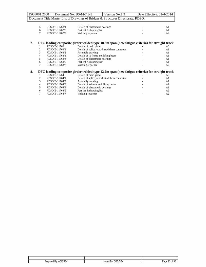
7. DFC loading composite girder welded type 18.3m span (new fatigue criteria) for straight track 1 RDSO/B-11763 Details of main girder - A0
2 RDSO/B-11763/1 Details of splice joint & stud shear connector - A1
3 RDSO/B-11763/2 Assembly drawing - A1 4 RDSO/B-11763/3 Details of x-frame and lifting beam - A1
5 RDSO/B-11763/4 Details of elastomeric bearings - A1
6 RDSO/B-11763/5 Part list & shipping list A1 7 RDSO/B-11763/7
Welding sequence - A2
8. DFC loading composite girder welded type 12.2m span (new fatigue criteria) for straight track 1 RDSO/B-11764 Details of main girder - A0
2 RDSO/B-11764/1 Details of splice joint & stud shear connector - A1
3 RDSO/B-11764/2 Assembly drawing - A1
4 RDSO/B-11764/3 Details of x-frame and lifting beam - A1
5 RDSO/B-11764/4 Details of elastomeric bearings - A1
6 RDSO/B-11764/5 Part list & shipping list A2 7 RDSO/B-11764/7 Welding sequence - A2
ISO9001:2008 Document No: BS-M-7.3-1 Version No:1.3 Date Effective: 01-4-2014
Document Title:Master List of Drawings of Bridges & Structures Directorate, RDSO.
Prepared By: ADE/SB-1 Issued By: DBS/SB-I Page 24 of 55
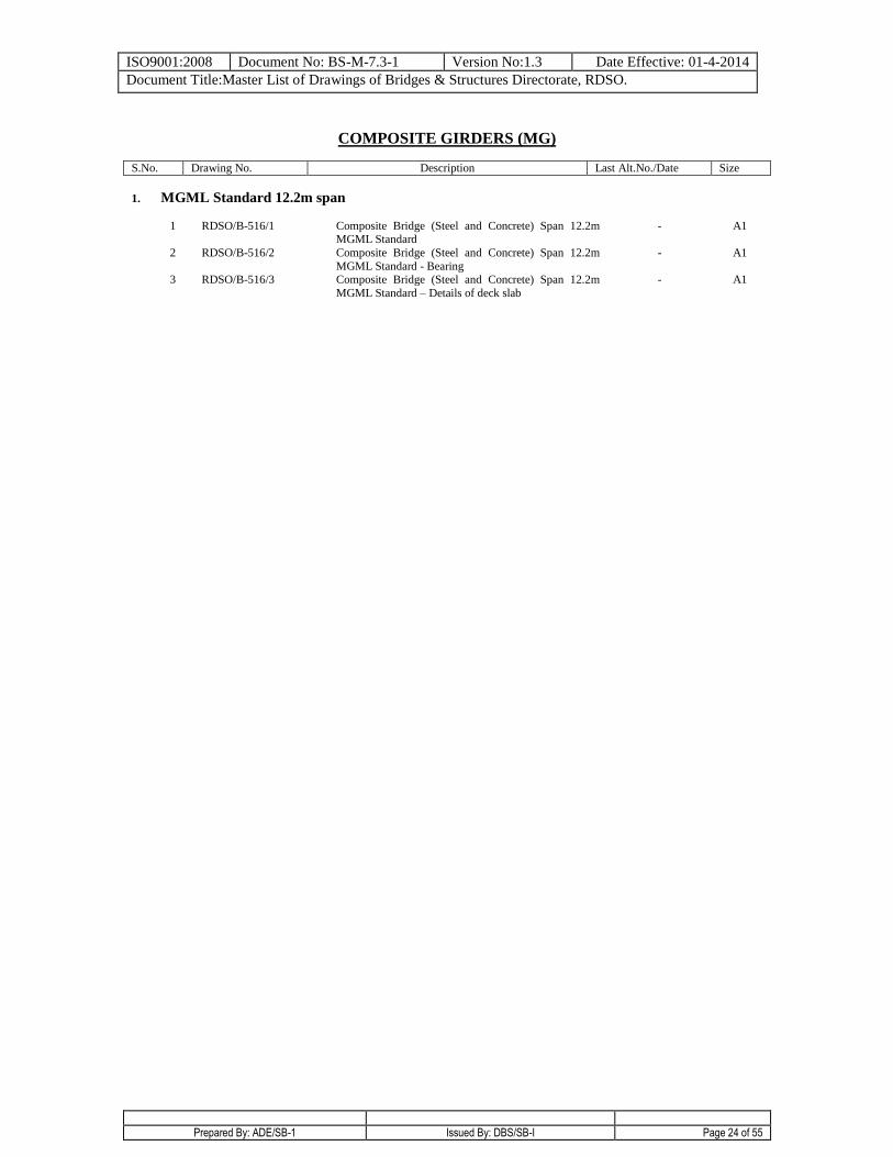
COMPOSITE GIRDERS (MG)
S.No. Drawing No. Description Last Alt.No./Date Size
1. MGML Standard 12.2m span
1 RDSO/B-516/1 Composite Bridge (Steel and Concrete) Span 12.2m MGML Standard
- A1
2 RDSO/B-516/2 Composite Bridge (Steel and Concrete) Span 12.2m
MGML Standard - Bearing
- A1
3 RDSO/B-516/3 Composite Bridge (Steel and Concrete) Span 12.2m
MGML Standard – Details of deck slab
- A1
ISO9001:2008 Document No: BS-M-7.3-1 Version No:1.3 Date Effective: 01-4-2014
Document Title:Master List of Drawings of Bridges & Structures Directorate, RDSO.
Prepared By: ADE/SB-1 Issued By: DBS/SB-I Page 25 of 55
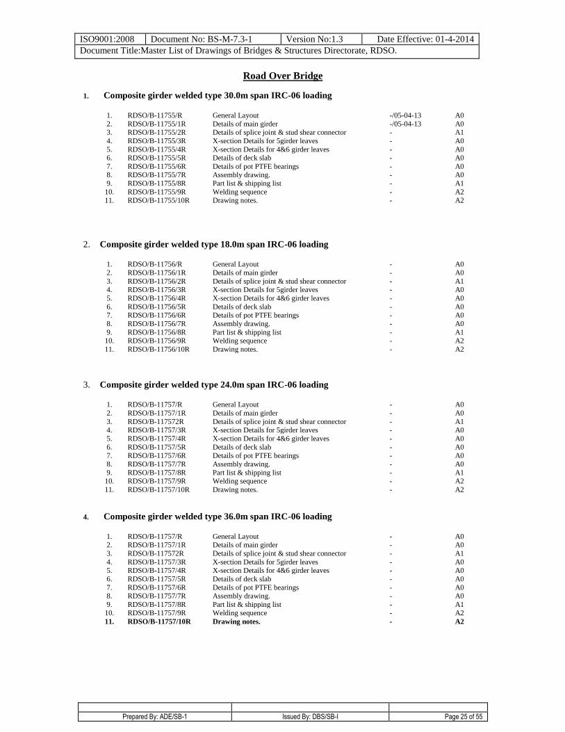
Road Over Bridge
1. Composite girder welded type 30.0m span IRC-06 loading
1. RDSO/B-11755/R General Layout -/05-04-13 A0
2. RDSO/B-11755/1R Details of main girder -/05-04-13 A0 3. RDSO/B-11755/2R Details of splice joint & stud shear connector - A1
4. RDSO/B-11755/3R X-section Details for 5girder leaves - A0
5. RDSO/B-11755/4R X-section Details for 4&6 girder leaves - A0 6. RDSO/B-11755/5R Details of deck slab - A0
7. RDSO/B-11755/6R Details of pot PTFE bearings - A0 8. RDSO/B-11755/7R Assembly drawing. - A0
9. RDSO/B-11755/8R Part list & shipping list - A1
10. RDSO/B-11755/9R Welding sequence - A2 11. RDSO/B-11755/10R Drawing notes. - A2
2. Composite girder welded type 18.0m span IRC-06 loading
1. RDSO/B-11756/R General Layout - A0
2. RDSO/B-11756/1R Details of main girder - A0
3. RDSO/B-11756/2R Details of splice joint & stud shear connector - A1 4. RDSO/B-11756/3R X-section Details for 5girder leaves - A0
5. RDSO/B-11756/4R X-section Details for 4&6 girder leaves - A0
6. RDSO/B-11756/5R Details of deck slab - A0 7. RDSO/B-11756/6R Details of pot PTFE bearings - A0
8. RDSO/B-11756/7R Assembly drawing. - A0
9. RDSO/B-11756/8R Part list & shipping list - A1 10. RDSO/B-11756/9R Welding sequence - A2
11. RDSO/B-11756/10R Drawing notes. - A2
3. Composite girder welded type 24.0m span IRC-06 loading
1. RDSO/B-11757/R General Layout - A0
2. RDSO/B-11757/1R Details of main girder - A0
3. RDSO/B-117572R Details of splice joint & stud shear connector - A1 4. RDSO/B-11757/3R X-section Details for 5girder leaves - A0
5. RDSO/B-11757/4R X-section Details for 4&6 girder leaves - A0
6. RDSO/B-11757/5R Details of deck slab - A0 7. RDSO/B-11757/6R Details of pot PTFE bearings - A0
8. RDSO/B-11757/7R Assembly drawing. - A0
9. RDSO/B-11757/8R Part list & shipping list - A1 10. RDSO/B-11757/9R Welding sequence - A2
11. RDSO/B-11757/10R Drawing notes. - A2
4. Composite girder welded type 36.0m span IRC-06 loading
1. RDSO/B-11757/R General Layout - A0
2. RDSO/B-11757/1R Details of main girder - A0
3. RDSO/B-117572R Details of splice joint & stud shear connector - A1
4. RDSO/B-11757/3R X-section Details for 5girder leaves - A0 5. RDSO/B-11757/4R X-section Details for 4&6 girder leaves - A0
6. RDSO/B-11757/5R Details of deck slab - A0
7. RDSO/B-11757/6R Details of pot PTFE bearings - A0 8. RDSO/B-11757/7R Assembly drawing. - A0
9. RDSO/B-11757/8R Part list & shipping list - A1 10. RDSO/B-11757/9R Welding sequence - A2
11.
RDSO/B-11757/10R Drawing notes.
- A2
ISO9001:2008 Document No: BS-M-7.3-1 Version No:1.3 Date Effective: 01-4-2014
Document Title:Master List of Drawings of Bridges & Structures Directorate, RDSO.
Prepared By: ADE/SB-1 Issued By: DBS/SB-I Page 26 of 55
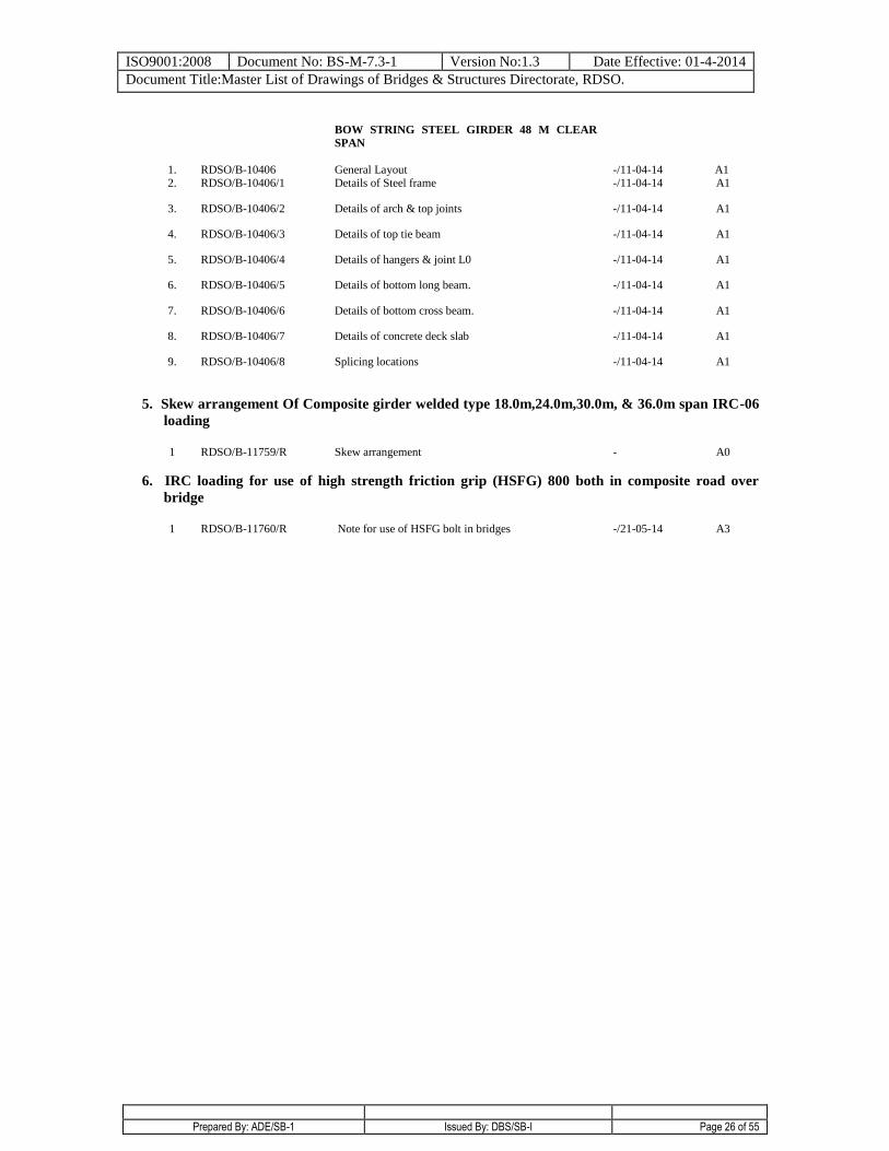
BOW STRING STEEL GIRDER 48 M CLEAR
SPAN
1. RDSO/B-10406 General Layout -/11-04-14 A1 2. RDSO/B-10406/1 Details of Steel frame -/11-04-14 A1
3. RDSO/B-10406/2 Details of arch & top joints -/11-04-14 A1
4. RDSO/B-10406/3 Details of top tie beam -/11-04-14 A1
5. RDSO/B-10406/4 Details of hangers & joint L0 -/11-04-14 A1
6. RDSO/B-10406/5 Details of bottom long beam. -/11-04-14 A1
7. RDSO/B-10406/6 Details of bottom cross beam. -/11-04-14 A1
8. RDSO/B-10406/7 Details of concrete deck slab -/11-04-14 A1
9. RDSO/B-10406/8 Splicing locations -/11-04-14 A1
5. Skew arrangement Of Composite girder welded type 18.0m,24.0m,30.0m, & 36.0m span IRC-06
loading
1 RDSO/B-11759/R Skew arrangement
- A0
6. IRC loading for use of high strength friction grip (HSFG) 800 both in composite road over
bridge
1 RDSO/B-11760/R Note for use of HSFG bolt in bridges
-/21-05-14 A3
ISO9001:2008 Document No: BS-M-7.3-1 Version No:1.3 Date Effective: 01-4-2014
Document Title:Master List of Drawings of Bridges & Structures Directorate, RDSO.
Prepared By: ADE/SB-1 Issued By: DBS/SB-I Page 27 of 55
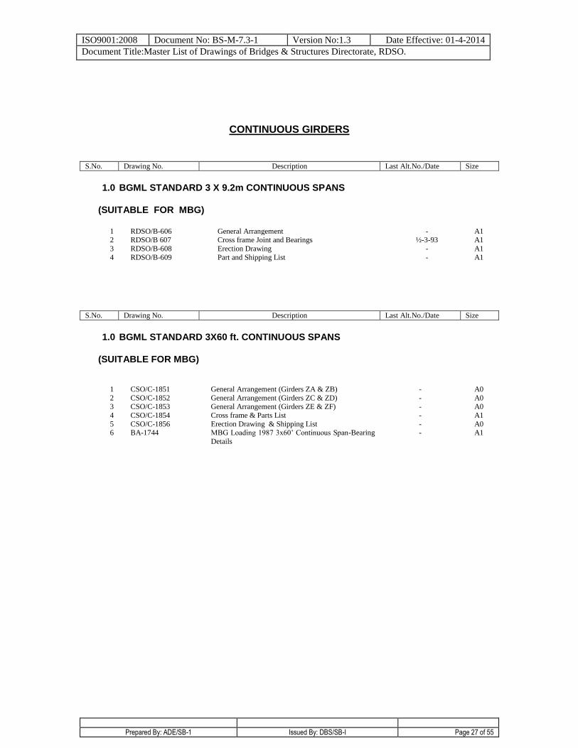
CONTINUOUS GIRDERS
S.No. Drawing No. Description Last Alt.No./Date Size
1.0 BGML STANDARD 3 X 9.2m CONTINUOUS SPANS
(SUITABLE FOR MBG)
1 RDSO/B-606 General Arrangement - A1
2 RDSO/B 607 Cross frame Joint and Bearings ½-3-93 A1
3 RDSO/B-608 Erection Drawing - A1
4 RDSO/B-609 Part and Shipping List - A1
S.No. Drawing No. Description Last Alt.No./Date Size
1.0 BGML STANDARD 3X60 ft. CONTINUOUS SPANS
(SUITABLE FOR MBG)
1 CSO/C-1851 General Arrangement (Girders ZA & ZB) - A0
2 CSO/C-1852 General Arrangement (Girders ZC & ZD) - A0 3 CSO/C-1853 General Arrangement (Girders ZE & ZF) - A0
4 CSO/C-1854 Cross frame & Parts List - A1
5 CSO/C-1856 Erection Drawing & Shipping List - A0 6 BA-1744 MBG Loading 1987 3x60’ Continuous Span-Bearing
Details
- A1
ISO9001:2008 Document No: BS-M-7.3-1 Version No:1.3 Date Effective: 01-4-2014
Document Title:Master List of Drawings of Bridges & Structures Directorate, RDSO.
Prepared By: ADE/SB-1 Issued By: DBS/SB-I Page 28 of 55
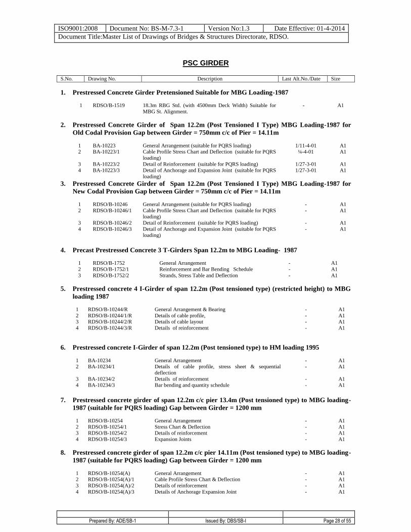
PSC GIRDER
S.No. Drawing No. Description Last Alt.No./Date Size
1. Prestressed Concrete Girder Pretensioned Suitable for MBG Loading-1987
1 RDSO/B-1519
18.3m RBG Std. (with 4500mm Deck Width) Suitable for
MBG St. Alignment.
-
A1
2. Prestressed Concrete Girder of Span 12.2m (Post Tensioned I Type) MBG Loading-1987 for
Old Codal Provision Gap between Girder = 750mm c/c of Pier = 14.11m
1 BA-10223 General Arrangement (suitable for PQRS loading) 1/11-4-01 A1
2 BA-10223/1 Cable Profile Stress Chart and Deflection (suitable for PQRS
loading)
¼-4-01 A1
3 BA-10223/2 Detail of Reinforcement (suitable for PQRS loading) 1/27-3-01 A1
4 BA-10223/3 Detail of Anchorage and Expansion Joint (suitable for PQRS
loading)
1/27-3-01 A1
3. Prestressed Concrete Girder of Span 12.2m (Post Tensioned I Type) MBG Loading-1987 for
New Codal Provision Gap between Girder = 750mm c/c of Pier = 14.11m
1 RDSO/B-10246 General Arrangement (suitable for PQRS loading) - A1
2 RDSO/B-10246/1 Cable Profile Stress Chart and Deflection (suitable for PQRS loading)
- A1
3 RDSO/B-10246/2 Detail of Reinforcement (suitable for PQRS loading) - A1
4 RDSO/B-10246/3 Detail of Anchorage and Expansion Joint (suitable for PQRS loading)
- A1
4. Precast Prestressed Concrete 3 T-Girders Span 12.2m to MBG Loading- 1987
1 RDSO/B-1752 General Arrangement - A1
2 RDSO/B-1752/1 Reinforcement and Bar Bending Schedule - A1
3 RDSO/B-1752/2 Strands, Stress Table and Deflection - A1
5. Prestressed concrete 4 I-Girder of span 12.2m (Post tensioned type) (restricted height) to MBG
loading 1987
1 RDSO/B-10244/R General Arrangement & Bearing - A1
2 RDSO/B-10244/1/R Details of cable profile, - A1 3 RDSO/B-10244/2/R Details of cable layout - A1
4 RDSO/B-10244/3/R Details of reinforcement - A1
6. Prestressed concrete I-Girder of span 12.2m (Post tensioned type) to HM loading 1995
1 BA-10234 General Arrangement - A1 2 BA-10234/1 Details of cable profile, stress sheet & sequential
deflection
- A1
3 BA-10234/2 Details of reinforcement - A1 4 BA-10234/3 Bar bending and quantity schedule - A1
7. Prestressed concrete girder of span 12.2m c/c pier 13.4m (Post tensioned type) to MBG loading-
1987 (suitable for PQRS loading) Gap between Girder = 1200 mm
1 RDSO/B-10254 General Arrangement - A1
2 RDSO/B-10254/1 Stress Chart & Deflection - A1 3 RDSO/B-10254/2 Details of reinforcement - A1
4 RDSO/B-10254/3 Expansion Joints - A1
8. Prestressed concrete girder of span 12.2m c/c pier 14.11m (Post tensioned type) to MBG loading-
1987 (suitable for PQRS loading) Gap between Girder = 1200 mm
1 RDSO/B-10254(A) General Arrangement - A1 2 RDSO/B-10254(A)/1 Cable Profile Stress Chart & Deflection - A1
3 RDSO/B-10254(A)/2 Details of reinforcement - A1
4 RDSO/B-10254(A)/3 Details of Anchorage Expansion Joint - A1
ISO9001:2008 Document No: BS-M-7.3-1 Version No:1.3 Date Effective: 01-4-2014
Document Title:Master List of Drawings of Bridges & Structures Directorate, RDSO.
Prepared By: ADE/SB-1 Issued By: DBS/SB-I Page 29 of 55
S.No. Drawing No. Description Last Alt.No./Date Size
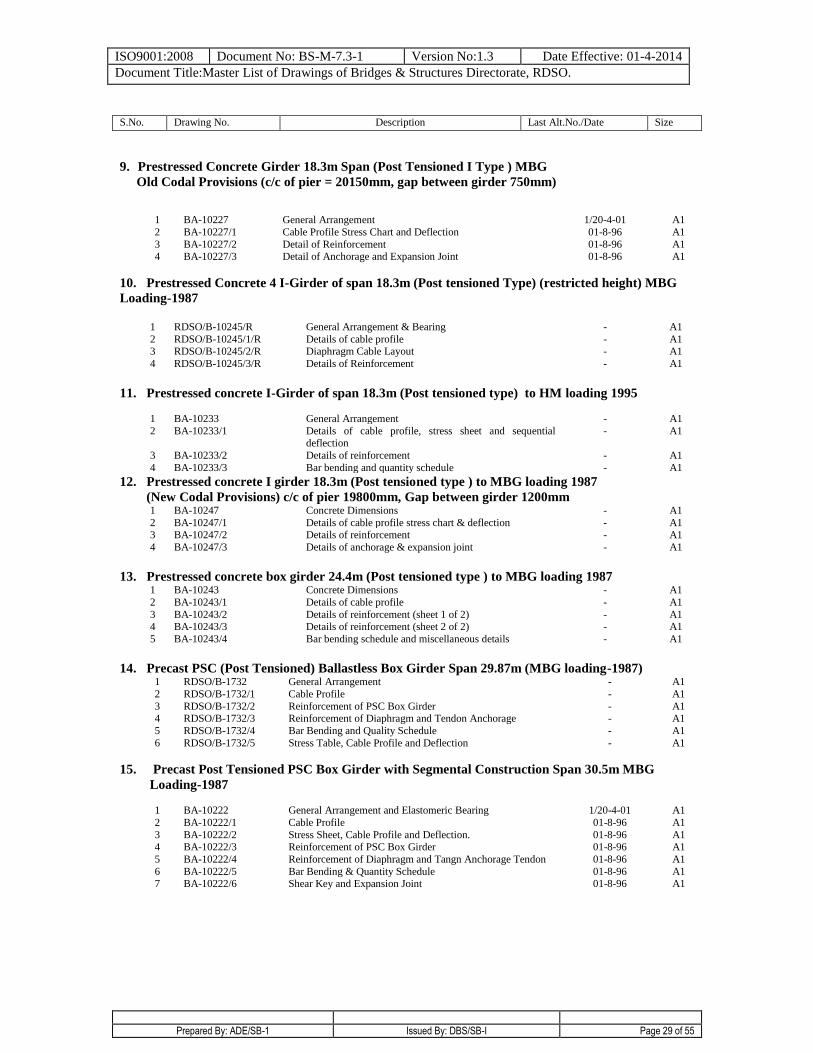
9. Prestressed Concrete Girder 18.3m Span (Post Tensioned I Type ) MBG
Old Codal Provisions (c/c of pier = 20150mm, gap between girder 750mm)
1 BA-10227 General Arrangement 1/20-4-01 A1
2 BA-10227/1 Cable Profile Stress Chart and Deflection 01-8-96 A1
3 BA-10227/2 Detail of Reinforcement 01-8-96 A1
4 BA-10227/3 Detail of Anchorage and Expansion Joint 01-8-96 A1
10. Prestressed Concrete 4 I-Girder of span 18.3m (Post tensioned Type) (restricted height) MBG
Loading-1987
1 RDSO/B-10245/R General Arrangement & Bearing - A1
2 RDSO/B-10245/1/R Details of cable profile - A1 3 RDSO/B-10245/2/R Diaphragm Cable Layout - A1
4 RDSO/B-10245/3/R Details of Reinforcement - A1
11. Prestressed concrete I-Girder of span 18.3m (Post tensioned type) to HM loading 1995
1 BA-10233 General Arrangement - A1
2 BA-10233/1 Details of cable profile, stress sheet and sequential deflection
- A1
3 BA-10233/2 Details of reinforcement - A1
4 BA-10233/3 Bar bending and quantity schedule - A1
12. Prestressed concrete I girder 18.3m (Post tensioned type ) to MBG loading 1987
(New Codal Provisions) c/c of pier 19800mm, Gap between girder 1200mm 1 BA-10247 Concrete Dimensions - A1
2 BA-10247/1 Details of cable profile stress chart & deflection - A1 3 BA-10247/2 Details of reinforcement - A1
4 BA-10247/3 Details of anchorage & expansion joint - A1
13. Prestressed concrete box girder 24.4m (Post tensioned type ) to MBG loading 1987 1 BA-10243 Concrete Dimensions - A1
2 BA-10243/1 Details of cable profile - A1
3 BA-10243/2 Details of reinforcement (sheet 1 of 2) - A1 4 BA-10243/3 Details of reinforcement (sheet 2 of 2) - A1
5 BA-10243/4 Bar bending schedule and miscellaneous details - A1
14. Precast PSC (Post Tensioned) Ballastless Box Girder Span 29.87m (MBG loading-1987) 1 RDSO/B-1732 General Arrangement - A1
2 RDSO/B-1732/1 Cable Profile - A1
3 RDSO/B-1732/2 Reinforcement of PSC Box Girder - A1
4 RDSO/B-1732/3 Reinforcement of Diaphragm and Tendon Anchorage - A1
5 RDSO/B-1732/4 Bar Bending and Quality Schedule - A1
6 RDSO/B-1732/5 Stress Table, Cable Profile and Deflection - A1
15. Precast Post Tensioned PSC Box Girder with Segmental Construction Span 30.5m MBG
Loading-1987
1 BA-10222 General Arrangement and Elastomeric Bearing 1/20-4-01 A1
2 BA-10222/1 Cable Profile 01-8-96 A1
3 BA-10222/2 Stress Sheet, Cable Profile and Deflection. 01-8-96 A1
4 BA-10222/3 Reinforcement of PSC Box Girder 01-8-96 A1
5 BA-10222/4 Reinforcement of Diaphragm and Tangn Anchorage Tendon 01-8-96 A1
6 BA-10222/5 Bar Bending & Quantity Schedule 01-8-96 A1
7 BA-10222/6 Shear Key and Expansion Joint
01-8-96 A1
ISO9001:2008 Document No: BS-M-7.3-1 Version No:1.3 Date Effective: 01-4-2014
Document Title:Master List of Drawings of Bridges & Structures Directorate, RDSO.
Prepared By: ADE/SB-1 Issued By: DBS/SB-I Page 30 of 55
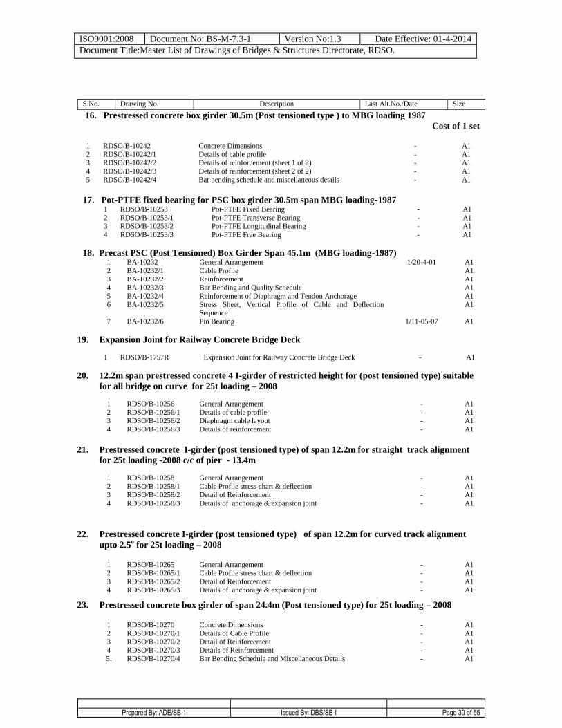
16. Prestressed concrete box girder 30.5m (Post tensioned type ) to MBG loading 1987
Cost of 1 set
1 RDSO/B-10242 Concrete Dimensions - A1
2 RDSO/B-10242/1 Details of cable profile - A1 3 RDSO/B-10242/2 Details of reinforcement (sheet 1 of 2) - A1
4 RDSO/B-10242/3 Details of reinforcement (sheet 2 of 2) - A1
5 RDSO/B-10242/4 Bar bending schedule and miscellaneous details - A1
17. Pot-PTFE fixed bearing for PSC box girder 30.5m span MBG loading-1987 1 RDSO/B-10253 Pot-PTFE Fixed Bearing - A1
2 RDSO/B-10253/1 Pot-PTFE Transverse Bearing - A1 3 RDSO/B-10253/2 Pot-PTFE Longitudinal Bearing - A1
4 RDSO/B-10253/3 Pot-PTFE Free Bearing - A1
18. Precast PSC (Post Tensioned) Box Girder Span 45.1m (MBG loading-1987) 1 BA-10232 General Arrangement 1/20-4-01 A1
2 BA-10232/1 Cable Profile A1
3 BA-10232/2 Reinforcement A1
4 BA-10232/3 Bar Bending and Quality Schedule A1
5 BA-10232/4 Reinforcement of Diaphragm and Tendon Anchorage A1
6 BA-10232/5 Stress Sheet, Vertical Profile of Cable and Deflection
Sequence
A1
7 BA-10232/6 Pin Bearing 1/11-05-07 A1
19. Expansion Joint for Railway Concrete Bridge Deck
1 RDSO/B-1757R Expansion Joint for Railway Concrete Bridge Deck
- A1
20. 12.2m span prestressed concrete 4 I-girder of restricted height for (post tensioned type) suitable
for all bridge on curve for 25t loading – 2008
1 RDSO/B-10256 General Arrangement - A1
2 RDSO/B-10256/1 Details of cable profile - A1
3 RDSO/B-10256/2 Diaphragm cable layout - A1
4 RDSO/B-10256/3 Details of reinforcement - A1
21. Prestressed concrete I-girder (post tensioned type) of span 12.2m for straight track alignment
for 25t loading -2008 c/c of pier - 13.4m
1 RDSO/B-10258 General Arrangement - A1
2 RDSO/B-10258/1 Cable Profile stress chart & deflection - A1
3 RDSO/B-10258/2 Detail of Reinforcement - A1
4 RDSO/B-10258/3 Details of anchorage & expansion joint - A1
22. Prestressed concrete I-girder (post tensioned type) of span 12.2m for curved track alignment
upto 2.5o for 25t loading – 2008
1 RDSO/B-10265 General Arrangement - A1
2 RDSO/B-10265/1 Cable Profile stress chart & deflection - A1
3 RDSO/B-10265/2 Detail of Reinforcement - A1
4 RDSO/B-10265/3 Details of anchorage & expansion joint - A1
23. Prestressed concrete box girder of span 24.4m (Post tensioned type) for 25t loading – 2008
1 RDSO/B-10270 Concrete Dimensions - A1
2 RDSO/B-10270/1 Details of Cable Profile - A1
3 RDSO/B-10270/2 Detail of Reinforcement - A1
4 RDSO/B-10270/3 Details of Reinforcement - A1
5. RDSO/B-10270/4 Bar Bending Schedule and Miscellaneous Details - A1
S.No. Drawing No. Description Last Alt.No./Date Size
ISO9001:2008 Document No: BS-M-7.3-1 Version No:1.3 Date Effective: 01-4-2014
Document Title:Master List of Drawings of Bridges & Structures Directorate, RDSO.
Prepared By: ADE/SB-1 Issued By: DBS/SB-I Page 31 of 55
24. Precast 21 concrete box girder of span 18.3m (Post tensioned type) for 25t loading – 2008
1 RDSO/B-10273 General Arrangement - A1
2 RDSO/B-10273/1 Cable Profile stress chart & deflection - A1
3 RDSO/B-10273/2 Detail of Reinforcement - A1
4 RDSO/B-10273/3 Details of anchorage & expansion joint - A1
5. RDSO/B-10273/4 Elastomeric bearing & seismic Resrainer - A1
ISO9001:2008 Document No: BS-M-7.3-1 Version No:1.3 Date Effective: 01-4-2014
Document Title:Master List of Drawings of Bridges & Structures Directorate, RDSO.
Prepared By: ADE/SB-1 Issued By: DBS/SB-I Page 32 of 55
PSC SLABS
S.No. Drawing No. Description Last Alt.No./Date Size
1. Prestressed Concrete Slab Pretensioned to MGML Loading
1 BA-10208
Precast Prestressed Concrete Slab Top Span 6.1m
1/21-10-66
A1
2. Prestressed Concrete Slab Pretensioned to MBG Loading 1987 1 BA-10221/R Precast Prestressed Concrete Slab 6.1m 1/17-4-01 A1 2 BA-10235 Precast Prestressed Concrete Slab span 3. 05m 8-9-01 A1
3 BA-10236 Precast Prestressed Concrete Slab span 3.66m - A1
4 BA-10237 Precast Prestressed Concrete Slab span 4.57m - A1
5 RDSO/B-1601 Precast Prestressed Concrete Slabs Spans 3.05m, 3.66m,
4.57m and 6.1m for Meter Gauge (Suitable for MMG Loading-1988 and with additional Unit on Gauge
Conversion).
1/13-6-91 A1
6 BA-10228 Precast Prestressed Concrete Slabs Spans 3.66m, 4.57m and 6.1m for (Suitable for Gauge Conversion).
- A1
7 BA-10229 Precast RCC Bed Block for Multiple Spans of 3.66,
4.57m and 6.10m (Suitable for Gauge Conversion).
- A1
3. Pretensioned PSC Slab to MBG Loading-1987
1 BA-10239 Pretensioned PSC slab with 3 units span 6.1m
A1
2 BA-10240 Pretensioned PSC slab with 3 units span 9.15m 1/26-06-08 A1
4. Post tensioned PSC Slab with 2 units MBG Loading-1987 1 BA-10241 Post tensioned PSC Slab Span 9.15m
- A1
5. Post tensioned PSC Slab with 4 units MBG Loading-1987 12.2m span
1 BA-10248 General arrangement & cable profile
1/10-03-12 A1
2 BA-10248/1 Details of reinforcement 1/10-03-12 A1
6. Pretensioned PSC Slab to HM Loading 1995 1 BA-10238 Pretensioned PSC Slab with 3 units span 6.1m
31-1-02 A1
7. Precast Prestressed (Pretensioned) Concrete Slab HM Loading-1995
1 BA-10249 Precast prestressed (pretensioned) concrete slab span
3.05m
- A1
2 BA-10250 Precast prestressed (pretensioned) concrete slab span 3.66m
- A1
3. BA-10251 Precast prestressed (pretensioned) concrete slab span 4.57m
- A1
8. Post Tensioned PSC solid slab with 4-units H.M. loading 1995 12.2m 1.
1 RDSO/B-10255 General arrangement & cable profile
- A1
2 RDSO/B-10255/1 Details of reinforcement
- A1
3. RDSO/B-10255/2 Seismic restrainer of solid slab for single track
- A1
ISO9001:2008 Document No: BS-M-7.3-1 Version No:1.3 Date Effective: 01-4-2014
Document Title:Master List of Drawings of Bridges & Structures Directorate, RDSO.
Prepared By: ADE/SB-1 Issued By: DBS/SB-I Page 33 of 55
9. Precast prestressed (Pretensioned) concrete slab (2 unit) span 6.1m for 25t loading – 2008
1 RDSO/B-10257/R Concrete slab (2 unit) span 6.1m - A1
2 BA-10259 Concrete slab (2 unit) span 3.05m 1/12-02-14 A1
3 BA -10260 Concrete slab (2 unit) span 3.66m 1/12-02-14 A1
4 BA -10261 Concrete slab (2 unit) span 4.57m 1/12-02-14 A1
10. Precast prestressed (Pretensioned) concrete slab (3 unit) span 9.15m for 25t loading – 2008
1 BA -10263/R Concrete slab (3 unit) span 9.15m 1/12-02-14 A1
11. Precast prestressed (Pretensioned) concrete slab (3 unit) span 6.10m for DFC loading (32.5t)
axle load
1 RDSO/B-10264 Concrete slab (3 unit) span 6.10m - A1
2 RDSO/B-10266 Precast (pretensioned) concrete slab (2 unit) span 3.05m for
DFC loading (32.5t axle load)
- A1
3 RDSO/B-10267 Precast (pretensioned) concrete slab (2 unit) span 3.66m for DFC loading (32.5t axle load)
- A1
4 RDSO/B-10268 Precast (pretensioned) concrete slab (3 unit) span 4.57m for
DFC loading (32.5t axle load)
- A1
5 RDSO/B-10269 Precast (pretensioned) concrete slab (3 unit) span 9.15m for
DFC loading (32.5t axle load)
- A1
12 Post tensioned PSC Slab with 4 units 12.2m 25 t Loading-2008
1 RDSO/B-10271 General arrangement & cable profile 1/27-05-11 A1
2 RDSO/B-10271/1 Details of reinforcement
- A1
13 Post tensioned PSC Slab with 2 units 9.15m 25 t Loading-2008
1 RDSO/B-10272 General arrangement & cable profile - A1
ISO9001:2008 Document No: BS-M-7.3-1 Version No:1.3 Date Effective: 01-4-2014
Document Title:Master List of Drawings of Bridges & Structures Directorate, RDSO.
Prepared By: ADE/SB-1 Issued By: DBS/SB-I Page 34 of 55
REINFORCED CONCRETE SLABS (Ballasted)
S.No. Drawing No. Description Last Alt.No./Date Size
1. Precast R.C. Bridge Slab (MBG)
1 BA-10051 Span 0.61m, 0.915m, 1.22m, 1.83m & 2.44m (Concrete
Grade M-25)
1/23-4-00 A0
2 BA-10052 Span 0.61m, 0.915m, 1.22m, 1.83m & 2.44m (Concrete
Grade M-30)
1/23-4-00 A0
3 BA-10059 General arrangement and details of R.C. approach slab MBG laoding-1987
- A1
Precast R.C. Bridge Slab (HM Loading)
1 BA-10060 Precast RC bridge slab std. span 0.61, 0.915, 1.22, 1.83 &
2.44m HM loading-1995 (Conc. Grade M-30)
- A1
2. Precast RC Bridge Slab (Metre Gauge) Spans 0.61m, 0.915m, 1.22m, 1.83m and 2.44m (Suitable
for MMG and with Additional Unit for MBG for Gauge Conversion)
1
RDSO/B-1600
General Arrangement
-
A1
2 RDSO/B-1600/1 0.61m Quantity and Bar Bending Schedule - A1
3 RDSO/B-1600/2 0.915m Quantity and Bar Bending Schedule - A1
4 RDSO/B-1600/3 1.22m Quantity and Bar Bending Schedule - A1 5 RDSO/B-1600/4 1.83m Quantity and Bar Bending Schedule - A1
6 RDSO/B-1600/5 2.44m Quantity and Bar Bending Schedule - A1
3. Existing MGML Suitable for MBG for Gauge Conversion
1 RDSO/B-1740 2 Unit Slabs with Additional Unit for Gauge Conversion (M-25)
- A1
2 RDSO/B-1741 4 Unit Slabs with Additional Unit for Gauge Conversion
(M-25)
- A1
4. Existing MMG Suitable for MBG for Gauge Conversion
1 RDSO/B-1742 2 Unit Slabs with Additional Unit for Gauge Conversion
(M-25)
- A1
2 RDSO/B-1743 5 Unit Slabs with Additional Unit for Gauge Conversion (M-25)
- A1
5. Precast R.C. bridge slab (25t Loading – 2008)
1. BA-10063 Precast R.C. bridge Slab standard span 0.61, 0.915, 1.22,
1.83 & 2.44m 25t loading – 2008 (Concrete Grade M-25)
2/13-1-12 A1
2 BA-10063/1 Precast R.C. bridge Slab standard span 0.61, 0.915, 1.22,
1.83 & 2.44m 25t loading – 2008 (Concrete Grade M-35)Fr
several environment exposure condition.
1/03-01-14 A1
3 BA-10063/2 Precast R.C. bridge Slab standard span 0.61, 0.915, 1.22,
1.83 & 2.44m 25t loading – 2008 (Concrete Grade M-35)Fr
several environment exposure condition.
1/03-01-14 A1
6. Precast R.C. bridge slab (DFC Loading) (32.5t Axle Load)
1. BA-10062 Precast R.C. bridge Slab standard span 0.61, 0.915, 1.22,
1.83 & 2.44m DFC Loading (Concrete Grade M-30)
1/13-01-12 A1
2 BA-10062/1 Precast R.C. bridge Slab standard span 0.61, 0.915, 1.22, 1.83 & 2.44m DFC Loading (Concrete Grade M-30) For
several environment exposure condition.
1/03-01-14 A1
ISO9001:2008 Document No: BS-M-7.3-1 Version No:1.3 Date Effective: 01-4-2014
Document Title:Master List of Drawings of Bridges & Structures Directorate, RDSO.
Prepared By: ADE/SB-1 Issued By: DBS/SB-I Page 35 of 55
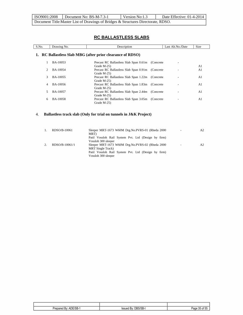
RC BALLASTLESS SLABS
S.No. Drawing No. Description Last Alt.No./Date Size
1. RC Ballastless Slab MBG (after prior clearance of RDSO)
1 BA-10053 Precast RC Ballastless Slab Span 0.61m (Concrete
Grade M-25)
-
A1
2 BA-10054 Precast RC Ballastless Slab Span 0.91m (Concrete Grade M-25)
- A1
3 BA-10055 Precast RC Ballastless Slab Span 1.22m (Concrete
Grade M-25)
- A1
4 BA-10056 Precast RC Ballastless Slab Span 1.83m (Concrete
Grade M-25)
- A1
5 BA-10057 Precast RC Ballastless Slab Span 2.44m (Concrete Grade M-25)
- A1
6 BA-10058 Precast RC Ballastless Slab Span 3.05m (Concrete
Grade M-25)
- A1
4. Ballastless track slab (Only for trial on tunnels in J&K Project)
1. RDSO/B-10061 Sleeper MRT-1673 W60M Drg.No.PVRS-01 (Rheda 2000 MRT)
Patil Vossloh Rail System Pvt. Ltd (Design by firm)
Vossloh 300 sleeper
- A2
2. RDSO/B-10061/1 Sleeper MRT-1673 W60M Drg.No.PVRS-02 (Rheda 2000
MRT Single Track)
Patil Vossloh Rail System Pvt. Ltd (Design by firm) Vossloh 300 sleeper
- A2
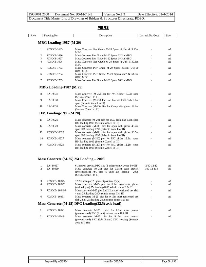
ISO9001:2008 Document No: BS-M-7.3-1 Version No:1.3 Date Effective: 01-4-2014
Document Title:Master List of Drawings of Bridges & Structures Directorate, RDSO.
Prepared By: ADE/SB-1 Issued By: DBS/SB-I Page 36 of 55
PIERS
S.No. Drawing No. Description Last Alt.No./Date Size
MBG Loading-1987 (M 20)
1 RDSO/B-1695 Mass Concrete Pier Grade M-20 Spans 6.10m & 9.15m
MBG
- A1
2 RDSO/B-1696 Mass Concrete Pier Grade M-20 Spans 12.2m MBG - A1
3 RDSO/B-1697 Mass Concrete Pier Grade M-20 Spans 18.3m MBG - A1
4 RDSO/B-1698 Mass Concrete Pier Grade M-20 Spans 24.4m & 30.5m MBG
- A1
5 RDSO/B-1733 Mass Concrete Pier Grade M-20 Spans 30.5m (US) &
(OW) MBG
- A1
6 RDSO/B-1734 Mass Concrete Pier Grade M-20 Spans 45.7 & 61.0m
(OW) MBG
- A1
7 RDSO/B-1735 Mass Concrete Pier Grade M-20 Spans 76.2m MBG
- A1
MBG Loading-1987 (M 25)
8 BA-10331 Mass Concrete (M-25) Pier for PSC Girder 12.2m span
(Seismic Zone I to III)
- A1
9 BA-10333 Mass Concrete (M-25) Pier for Precast PSC Slab 6.1m
span (Seismic Zone I to III)
- A1
10 BA-10335 Mass Concrete (M-25) Pier for Composite girder 12.2m (Seismic Zone I to III)
- A1
HM Loading-1995 (M 20)
11 BA-10321 Mass concrete (M-20) pier for PSC deck slab 6.1m span
HM loading 1995 (Seismic Zone I to III)
- A1
12 BA-10323 Mass concrete (M-20) pier for open web girder 45.7m
span HM loading 1995 (Seismic Zone I to III)
- A1
13 RDSO/B-10325 Mass concrete (M-20) pier for open web girder 30.5m span HM loading 1995 (Seismic Zone I to III)
- A1
14 RDSO/B-10327 Mass concrete (M-20) pier for PSC girder 18.3m span
HM loading 1995 (Seismic Zone I to III)
- A1
14 RDSO/B-10329 Mass concrete (M-20) pier for PSC girder 12.2m span
HM loading 1995 (Seismic Zone I to III)
- A1
Mass Concrete (M-25) 25t Loading – 2008
1 BA- 10337 6.1m span precast PSC slab (2 unit) seismic zones I to III 2/30-12-13 A1 2 BA- 10339 Mass concrete (M-25) pier for 9.15m span precast
(Pretensioned) PSC slab (3 unit) 25t loading - 2008
(Seismic Zone I to III)
1/30-12-113 A1
3 RDSO/B- 10345 12.2m span psc 2 I girder (post ten. Type) - A1
4 RDSO/B- 10347 Mass concrete M-25 pier for12.2m composite girder (welded type) 25t loading-2008 seimic zones II & III
- A1
5 RDSO/B- 10349R Mass concrete M-25 pier for12.2m post tensioned psc slab
4 unit 25t loading-2008 seimic zones II & III
- A1
6 RDSO/B- 10351 Mass concrete M-25 pier for 9.15m post tensioned psc
slab 2 unit 25t loading-2008 seimic zones II & III
- A1
Mass Concrete (M-25) DFC Loading(32.5t axle load)
1. RDSO/B- 10341 Mass concrete M-25 pier for 6.1m span precast (pretensioned) PSC (3 unit) seismic zone II & III
- A1
2. RDSO/B-10343 Mass concrete M-25 pier for 9.15m span precast
(pretensioned) PSC Slab (3 unit) DFC loading (Seismic zone II & III)
- A1
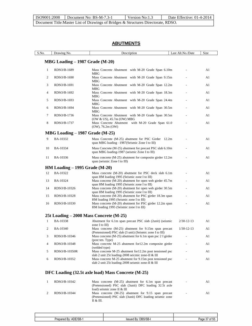
ISO9001:2008 Document No: BS-M-7.3-1 Version No:1.3 Date Effective: 01-4-2014
Document Title:Master List of Drawings of Bridges & Structures Directorate, RDSO.
Prepared By: ADE/SB-1 Issued By: DBS/SB-I Page 37 of 55
ABUTMENTS
S.No. Drawing No. Description Last Alt.No./Date Size
MBG Loading – 1987 Grade (M-20)
1 RDSO/B-1689 Mass Concrete Abutment with M-20 Grade Span 6.10m MBG
- A1
2 RDSO/B-1690 Mass Concrete Abutment with M-20 Grade Span 9.15m
MBG
- A1
3 RDSO/B-1691 Mass Concrete Abutment with M-20 Grade Span 12.2m
MBG
- A1
4 RDSO/B-1692 Mass Concrete Abutment with M-20 Grade Span 18.3m MBG
- A1
5 RDSO/B-1693 Mass Concrete Abutment with M-20 Grade Span 24.4m
MBG
- A1
6 RDSO/B-1694 Mass Concrete Abutment with M-20 Grade Span 30.5m
MBG
- A1
7 RDSO/B-1736 Mass Concrete Abutment with M-20 Grade Span 30.5m (OW & US), 45.7m (OW) MBG
- A1
8 RDSO/B-1737 Mass Concrete Abutment with M-20 Grade Span 61.0
(OW), 76.2m (OW)
- A1
MBG Loading – 1987 Grade (M-25)
9 BA-10332 Mass Concrete (M-25) abutment for PSC Girder 12.2m
span MBG loading –1987(Seismic Zone I to III)
- A1
10 BA-10334 Mass Concrete (M-25) abutment for precast PSC slab 6.10m span MBG loading-1987 (seismic Zone I to III)
- A1
11 BA-10336 Mass concrete (M-25) abutment for composite girder 12.2m
span (seismic Zone I to III)
- A1
HM Loading – 1995 Grade (M-20) 12 BA-10322 Mass concrete (M-20) abutment for PSC deck slab 6.1m
span HM loading 1995 (Seismic zone I to III)
- A1
13 BA-10324 Mass concrete (M-20) abutment for open web girder 45.7m span HM loading 1995 (Seismic zone I to III)
- A1
14 RDSO/B-10326 Mass concrete (M-20) abutment for open web girder 30.5m
span HM loading 1995 (Seismic zone I to III)
- A1
15 RDSO/B-10328 Mass concrete (M-20) abutment for PSC girder 18.3m span
HM loading 1995 (Seismic zone I to III)
- A1
16 RDSO/B-10330 Mass concrete (M-20) abutment for PSC girder 12.2m span HM loading 1995 (Seismic zone I to III)
- A1
25t Loading – 2008 Mass Concrete (M-25) 1 BA-10338 Abutment for 6.1m span precast PSC slab (2unit) (seismic
zone I to III)
2/30-12-13 A1
2 BA-10340 Mass concrete (M-25) abutment for 9.15m span precast
(Pretensioned) PSC slab (3 unit) (Seismic zone I to III)
1/30-12-13 A1
3 RDSO/B-10346 Mass concrete (M-25) abutment for 6.1m span psc 2 I girder (post ten. Type)
- A1
4 RDSO/B-10348 Mass concrete M-25 abutment for12.2m composite girder
(welded type)
- A1
5 RDSO/B-10350R Mass concrete M-25 abutment for12.2m post tensioned psc
slab 2 unit 25t loading-2008 seicmic zone-II & III
- A1
6 RDSO/B-10352 Mass concrete M-25 abutment for 9.15m post tensioned psc slab 2 unit 25t loading-2008 seismic zone-II & III
- A1
DFC Loading (32.5t axle load) Mass Concrete (M-25)
1 RDSO/B-10342 Mass concrete (M-25) abutment for 6.1m span precast (Pretensioned) PSC slab (3unit) DFC loading 32.5t axle
load) seismic zone II & III
- A1
2 RDSO/B-10344 Mass concrete (M-25) abutment for 9.15 span precast (Pretensioned) PSC slab (3unit) DFC loading seismic zone
II & III.
- A1
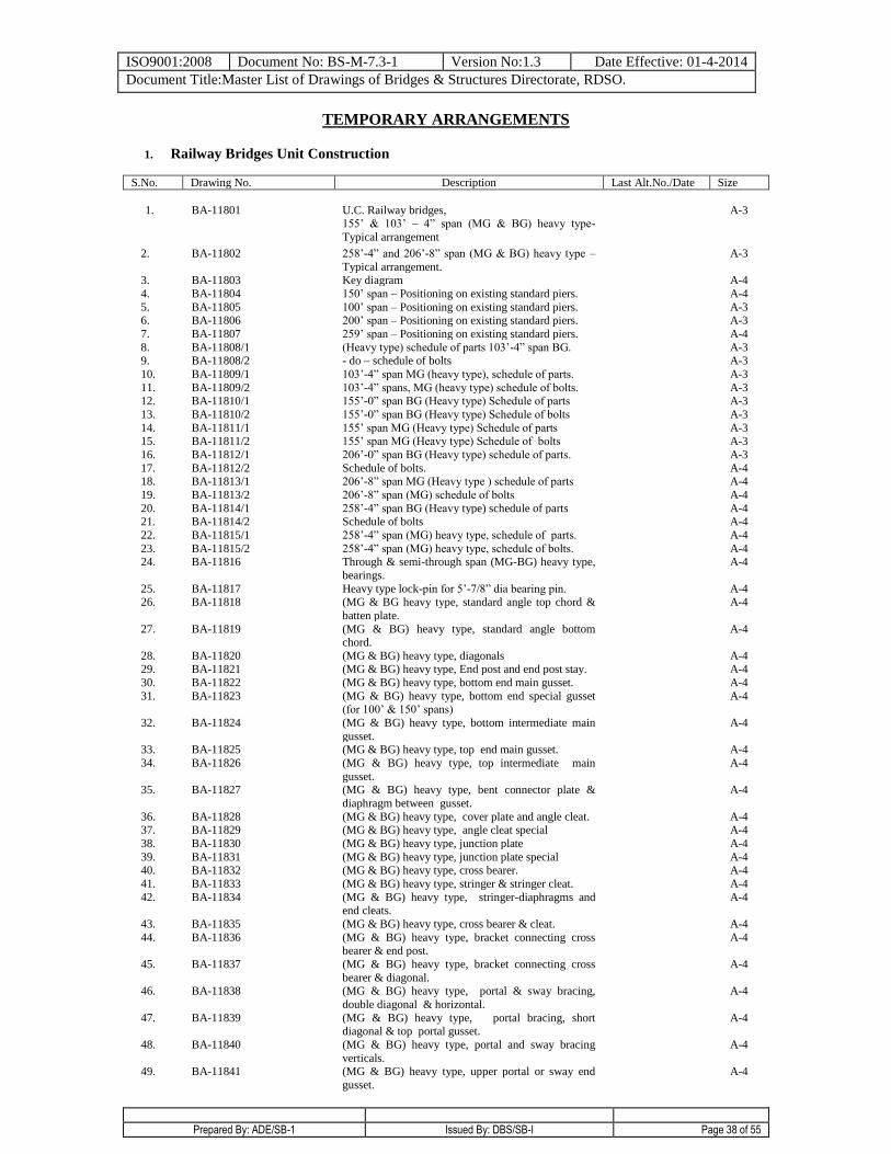
ISO9001:2008 Document No: BS-M-7.3-1 Version No:1.3 Date Effective: 01-4-2014
Document Title:Master List of Drawings of Bridges & Structures Directorate, RDSO.
Prepared By: ADE/SB-1 Issued By: DBS/SB-I Page 38 of 55
TEMPORARY ARRANGEMENTS
1. Railway Bridges Unit Construction
S.No. Drawing No. Description Last Alt.No./Date Size
1. BA-11801 U.C. Railway bridges, 155’ & 103’ – 4” span (MG & BG) heavy type-
Typical arrangement
A-3
2. BA-11802 258’-4” and 206’-8” span (MG & BG) heavy type –
Typical arrangement.
A-3
3. BA-11803 Key diagram A-4
4. BA-11804 150’ span – Positioning on existing standard piers. A-4
5. BA-11805 100’ span – Positioning on existing standard piers. A-3 6. BA-11806 200’ span – Positioning on existing standard piers. A-3
7. BA-11807 259’ span – Positioning on existing standard piers. A-4
8. BA-11808/1 (Heavy type) schedule of parts 103’-4” span BG. A-3 9. BA-11808/2 - do – schedule of bolts A-3
10. BA-11809/1 103’-4” span MG (heavy type), schedule of parts. A-3
11. BA-11809/2 103’-4” spans, MG (heavy type) schedule of bolts. A-3 12. BA-11810/1 155’-0” span BG (Heavy type) Schedule of parts A-3
13. BA-11810/2 155’-0” span BG (Heavy type) Schedule of bolts A-3
14. BA-11811/1 155’ span MG (Heavy type) Schedule of parts A-3 15. BA-11811/2 155’ span MG (Heavy type) Schedule of bolts A-3
16. BA-11812/1 206’-0” span BG (Heavy type) schedule of parts. A-3
17. BA-11812/2 Schedule of bolts. A-4 18. BA-11813/1 206’-8” span MG (Heavy type ) schedule of parts A-4
19. BA-11813/2 206’-8” span (MG) schedule of bolts A-4
20. BA-11814/1 258’-4” span BG (Heavy type) schedule of parts A-4 21. BA-11814/2 Schedule of bolts A-4
22. BA-11815/1 258’-4” span (MG) heavy type, schedule of parts. A-4
23. BA-11815/2 258’-4” span (MG) heavy type, schedule of bolts. A-4 24. BA-11816 Through & semi-through span (MG-BG) heavy type,
bearings.
A-4
25. BA-11817 Heavy type lock-pin for 5’-7/8” dia bearing pin. A-4 26. BA-11818 (MG & BG heavy type, standard angle top chord &
batten plate.
A-4
27. BA-11819 (MG & BG) heavy type, standard angle bottom chord.
A-4
28. BA-11820 (MG & BG) heavy type, diagonals A-4 29. BA-11821 (MG & BG) heavy type, End post and end post stay. A-4
30. BA-11822 (MG & BG) heavy type, bottom end main gusset. A-4
31. BA-11823 (MG & BG) heavy type, bottom end special gusset (for 100’ & 150’ spans)
A-4
32. BA-11824 (MG & BG) heavy type, bottom intermediate main
gusset.
A-4
33. BA-11825 (MG & BG) heavy type, top end main gusset. A-4
34. BA-11826 (MG & BG) heavy type, top intermediate main
gusset.
A-4
35. BA-11827 (MG & BG) heavy type, bent connector plate &
diaphragm between gusset.
A-4
36. BA-11828 (MG & BG) heavy type, cover plate and angle cleat. A-4 37. BA-11829 (MG & BG) heavy type, angle cleat special A-4
38. BA-11830 (MG & BG) heavy type, junction plate A-4
39. BA-11831 (MG & BG) heavy type, junction plate special A-4 40. BA-11832 (MG & BG) heavy type, cross bearer. A-4
41. BA-11833 (MG & BG) heavy type, stringer & stringer cleat. A-4
42. BA-11834 (MG & BG) heavy type, stringer-diaphragms and end cleats.
A-4
43. BA-11835 (MG & BG) heavy type, cross bearer & cleat. A-4
44. BA-11836 (MG & BG) heavy type, bracket connecting cross bearer & end post.
A-4
45. BA-11837 (MG & BG) heavy type, bracket connecting cross
bearer & diagonal.
A-4
46. BA-11838 (MG & BG) heavy type, portal & sway bracing,
double diagonal & horizontal.
A-4
47. BA-11839 (MG & BG) heavy type, portal bracing, short diagonal & top portal gusset.
A-4
48. BA-11840 (MG & BG) heavy type, portal and sway bracing
verticals.
A-4
49. BA-11841 (MG & BG) heavy type, upper portal or sway end
gusset.
A-4
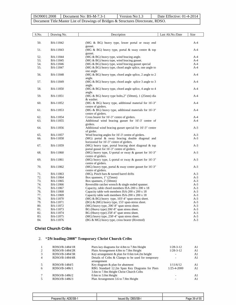
ISO9001:2008 Document No: BS-M-7.3-1 Version No:1.3 Date Effective: 01-4-2014
Document Title:Master List of Drawings of Bridges & Structures Directorate, RDSO.
Prepared By: ADE/SB-1 Issued By: DBS/SB-I Page 39 of 55
S.No. Drawing No. Description Last Alt.No./Date Size
50. BA-11842 (MG & BG) heavy type, lower portal or sway end
gusset. A-4
51. BA-11843 (MG & BG) heavy type, portal & sway centre & top
gusset.
A-4
52. BA-11844 (MG & BG) heavy type, wind bracing angle. A-4
53. BA-11845 (MG & BG) heavy type, wind bracing gusset. A-4
54. BA-11846 (MG & BG) heavy type, wind bracing gusset special A-4 55. BA-11847 (MG & BG) heavy type, chord angle splice, one angle to
one angle
A-4
56. BA-11848 (MG & BG) heavy type, chord angle splice, 2 angle to 2 angle.
A-4
57. BA-11849 (MG & BG) heavy type, chord angle splice 3 angle to 3
angle.
A-4
58. BA-11850 (MG & BG) heavy type, chord angle splice, 4 angle to 4
angle.
A-4
59. BA-11851 (MG & BG) heavy type bolts,2" (50mm), 1 (25mm) dia & washer.
A-4
60. BA-11852 (MG & BG) heavy type, additional material for 16'-3"
centre of girders.
A-4
61. BA-11853 (MG & BG) heavy type, additional materials for 16'-3"
centre of girders.
A-4
62. BA-11854 Cross bearer for 16'-3" centre of girders. A-4
63. BA-11855 Additional wind bracing gusset for 16'-3' centre of
girders.
A-4
64. BA-11856 Additional wind bracing gusset special for 16'-3" centre
of girder.
A-3
65. BA-11857 Wind bracing angles for 16'-3' centre of girders. A-3 66. BA-11858 (MG) portal & sway bracing double diagonal and
horizontal for 16'-3" centre of girders.
A-3
67. BA-11859 (MG) heavy type, portal bracing short diagonal & top portal gusset for 16'-3" centre of girders.
A-3
68. BA-11860 (MG) heavy type, U-portal or sway & gusset for 16'-3"
centre of girders.
A-3
69. BA-11861 (MG) heavy type, L-portal or sway & gusset for 16'-3"
centre of girders.
A-3
70. BA-11862 (MG) heavy type, portal & sway centre gusset for 16'-3" centre of girders.
A-3
71. BA-11863 (MG), Pinch bars & turned barrel drifts A-3
72. BA-11864 Box spanners, 1" (25mm) A-3 73. BA-11865 Box spanners, 2' (50mm) A-3
74. BA-11866 Reversible ratchet wrench & single ended spanner. A-3
75. BA-11867 Capacity, table chord members ISA-200 x 200 x 18 A-3 76. BA-11868 Capacity table web members ISA-200 x 200 x 18 A-3
77. BA-11869 Capacity table web members ISA-200 x 200 x 18 A-3
78. BA-11870 (MG & BG) heavy type, 103'-4" span-stress sheet. A-3 79. BA-11871 (BG) & (MG) heavy type, 155' span-stress sheet. A-3
80. BA-11872 (MG) heavy type, 206'-8" span stress sheet. A-3
81. BA-11873 BG (Heavy type) 206'-8" span stress sheet. A-3 82. BA-11874 BG (Heavy type) 258'-4" span stress sheet. A-3
83. BA-11875 (MG) heavy type, 258'-4" span stress sheet. A-3
84. BA-11876 (BG & MG) heavy type, cross bearer (Rivetted) A-3
Christ Church Cribs
2. “25t loading-2008” Temporary Christ Church Cribs
1 RDSO/B-1484/1R Piers key diagrams for 4.8m to 7.8m Height 1/28-3-12 A1 2 RDSO/B-1484/2R Plain Arrangement 4.8m to 7.8m Height 1/28-3-12 A1
3 RDSO/B-1484/3R Key arrangement & plan for 0.6m to4.2m height - A1
4 RDSO/B-1484/4R Details of Cribs & Clamps to be used for temporary arrangement
- A1
5 RDSO/B-1484/5 Key diagram & plan for abutment 1/11/6/12 A1
6 RDSO/B-1486/1 RBG Standard 12.2m Span Key Diagrams for Piers 3.6m to 7.8m Height Christ Church Cribs
1/25-4-2000 A1
7 RDSO/B-1486/2 0.6m to 3.0m Height - A1
5 RDSO/B-1486/3 Plan Arrangement 3.6 to 7.8m Height
-
A1
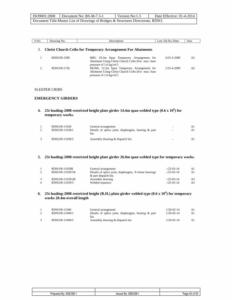
ISO9001:2008 Document No: BS-M-7.3-1 Version No:1.3 Date Effective: 01-4-2014
Document Title:Master List of Drawings of Bridges & Structures Directorate, RDSO.
Prepared By: ADE/SB-1 Issued By: DBS/SB-I Page 40 of 55
S.No. Drawing No. Description Last Alt.No./Date Size
3. Christ Church Cribs for Temporary Arrangement For Abutments
1 RDSO/B-1589 RBG 18.3m Span Temporary Arrangement for Abutment Using Christ Church Cribs (For max. base
pressure of 1.6 kg/cm2)
3/25-4-2000 A2
2 RDSO/B-1726 MGML 12.2m Span Temporary Arrangement for Abutment Using Christ Church Cribs (For max. base
pressure of 1.0 kg/cm2)
1/25-4-2000 A2
SLEEPER CRIBS
EMERGENCY GIRDERS
4. 25t loading-2008 restricted height plate girder 14.4m span welded type (0.6 x 10⁶) for
temporary works.
1 RDSO/B-11038 General arrangement - A1 2 RDSO/B-11038/1 Details of splice joint, diaphragms, bearing & part
list.
- A1
3 RDSO/B-11038/2 Assembly drawing & dispatch list.
- A1
5. 25t loading-2008 restricted height plate girder 26.8m span welded type for temporary works.
1 RDSO/B-11039R General arrangement -/25-03-14 A1 2 RDSO/B-11039/1R Details of splice joint, diaphragms, X-frame bearings
& part dispatch list.
-/25-03-14 A1
3 RDSO/B-11039/2R Assembly drawing -/25-03-14 A3 4 RDSO/B-11039/3
Welded sequence -/25-03-14 A3
6. 25t loading-2008 restricted height (R.H.) plate girder welded type (0.6 x 10⁶) for temporary
works 20.4m overall length
1 RDSO/B-11040 General arrangement 1/26-02-14 A1
2 RDSO/B-11040/1 Details of splice joint, diaphragms, bearing & part
list.
1/26-02-14 A1
3 RDSO/B-11040/2 Assembly drawing & dispatch list. 1/26-02-14 A1
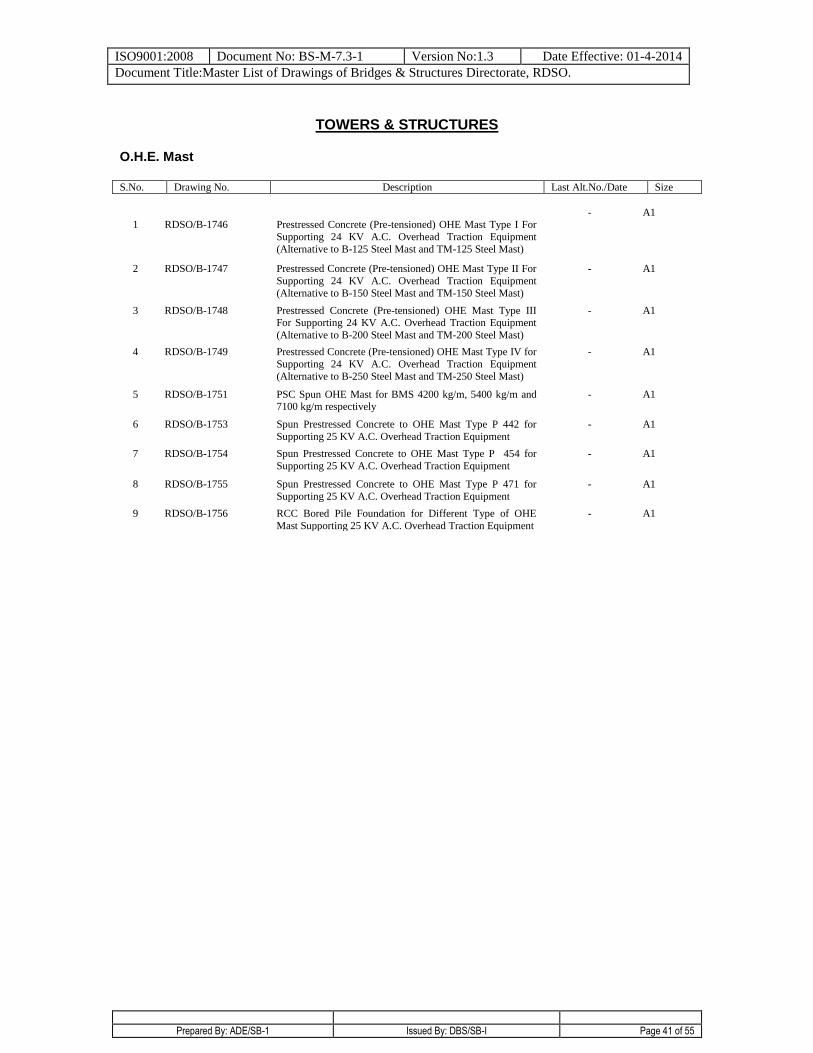
ISO9001:2008 Document No: BS-M-7.3-1 Version No:1.3 Date Effective: 01-4-2014
Document Title:Master List of Drawings of Bridges & Structures Directorate, RDSO.
Prepared By: ADE/SB-1 Issued By: DBS/SB-I Page 41 of 55
TOWERS & STRUCTURES
O.H.E. Mast
S.No. Drawing No. Description Last Alt.No./Date Size
1
RDSO/B-1746
Prestressed Concrete (Pre-tensioned) OHE Mast Type I For
Supporting 24 KV A.C. Overhead Traction Equipment
(Alternative to B-125 Steel Mast and TM-125 Steel Mast)
- A1
2 RDSO/B-1747 Prestressed Concrete (Pre-tensioned) OHE Mast Type II For
Supporting 24 KV A.C. Overhead Traction Equipment
(Alternative to B-150 Steel Mast and TM-150 Steel Mast)
- A1
3 RDSO/B-1748 Prestressed Concrete (Pre-tensioned) OHE Mast Type III For Supporting 24 KV A.C. Overhead Traction Equipment
(Alternative to B-200 Steel Mast and TM-200 Steel Mast)
- A1
4 RDSO/B-1749 Prestressed Concrete (Pre-tensioned) OHE Mast Type IV for
Supporting 24 KV A.C. Overhead Traction Equipment
(Alternative to B-250 Steel Mast and TM-250 Steel Mast)
- A1
5 RDSO/B-1751 PSC Spun OHE Mast for BMS 4200 kg/m, 5400 kg/m and 7100 kg/m respectively
- A1
6 RDSO/B-1753 Spun Prestressed Concrete to OHE Mast Type P 442 for
Supporting 25 KV A.C. Overhead Traction Equipment
- A1
7 RDSO/B-1754 Spun Prestressed Concrete to OHE Mast Type P 454 for
Supporting 25 KV A.C. Overhead Traction Equipment
- A1
8 RDSO/B-1755 Spun Prestressed Concrete to OHE Mast Type P 471 for
Supporting 25 KV A.C. Overhead Traction Equipment
- A1
9 RDSO/B-1756 RCC Bored Pile Foundation for Different Type of OHE
Mast Supporting 25 KV A.C. Overhead Traction Equipment
- A1
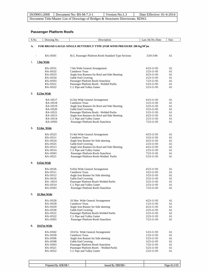
ISO9001:2008 Document No: BS-M-7.3-1 Version No:1.3 Date Effective: 01-4-2014
Document Title:Master List of Drawings of Bridges & Structures Directorate, RDSO.
Prepared By: ADE/SB-1 Issued By: DBS/SB-I Page 42 of 55
Passenger Platform Roofs
S.No. Drawing No. Description Last Alt.No./Date Size
A. FOR BROAD GAUGE-SINGLE BUTTERFLY TYPE (FOR WIND PRESSURE 200 Kg/M2)m
-
RA-10501
B.G. Passenger Platform Roofs Standard Type Sections
3/29-3-84
A1
1. 7.0m Wide
RA-10531 7.0m Wide General Arrangement 4/23-11-93 A1
RA-10532 Cantilever Truss 2/23-11-93 A1 RA-10533 Angle Iron Runners for Roof and Side Sheeting 4/23-11-93 A1
RA-10534 Gable End Covering 2/23-11-93 A1
RA-10503 Passenger Platform Roofs Stanchion 7/23-11-93 A1 RA-10521 Passenger Platform Roofs –Welded Purlin 5/23-11-93 A1
RA-10522 C.I. Pipe and Valley Gutter
2/23-11-93 A1
2. 8.23m Wide
RA-10517 8.23m Wide General Arrangement 4/23-11-93 A1 RA-10518 Cantilever Truss 3/23-11-93 A1
RA-10519 Angle Iron Runners for Roof and Side Sheeting 5/23-11-93 A1 RA-10520 Gable End Covering 3/23-11-93 A1
RA-10521 Passenger Platform Roofs –Welded Purlin 5/23-11-93 A1
RA-10513 Angle Iron Runners for Roof and Side Sheeting 4/23-11-93 A1 RA-10514 C.I. Pipe and Valley Gutter 2/23-11-93 A1
RA-10503 Passenger Platform Roofs Stanchion
7/23-11-93 A1
3. 9.14m Wide
RA-10523 9.14m Wide General Arrangement 4/23-11-93 A1 RA-10511 Cantilever Truss 3/23-11-93 A1
RA-10524 Angle Iron Runner for Side sheeting 4/23-11-93 A1
RA-10525 Gable End Covering 2/23-11-93 A1 RA-10513 Angle Iron Runners for Roof and Side Sheeting 4/23-11-93 A1
RA-10514 C.I. Pipe and Valley Gutter 2/23-11-93 A1
RA-10503 Passenger Platform Roofs Stanchion 7/23-11-93 A1 RA-10521 Passenger Platform Roofs-Welded Purlin 5/23-11-93 A1
4. 9.45m Wide
RA-10526 9.45m Wide General Arrangement 4/23-11-93 A1
RA-10511 Cantilever Truss 3/23-11-93 A1 RA-10512 Angle Iron Runner for Side sheeting 3/23-11-93 A1
RA-10516 Gable End Covering 3/23-11-93 A1
RA- 10521 Passenger Platform Roofs-Welded Purlin 5/23-11-93 A1 RA-10514 C.I. Pipe and Valley Gutter 2/23-11-93 A1
RA-10503 Passenger Platform Roofs Stanchion
7/23-11-93 A1
5. 10.36m Wide
RA-10528 10.36m Wide General Arrangement 4/23-11-93 A1 RA-10539 Cantilever Truss 1/23-11-93 A1
RA-10529 Angle Iron Runner for Side sheeting 4/23-11-93 A1
RA-10530 Gable End Covering 2/23-11-93 A1 RA-10521 Passenger Platform Roofs-Welded Purlin 5/23-11-93 A1
RA-10522 C.I. Pipe and Valley Gutter 2/23-11-93 A1
RA-10503 Passenger Platform Roofs Stanchion
7/23-11-93 A1
6. 10.67m Wide
RA-10502 10.67m Wide General Arrangement 5/23-11-93 A1
RA-10539 Cantilever Truss 1/23-11-93 A1
RA-10506 Angle Iron Runner for Side sheeting 5/23-11-93 A1 RA-10508 Gable End Covering . 3/23-11-93 A1
RA-10503 Passenger Platform Roofs Stanchion 7/23-11-93 A1
RA-10521 Passenger Platform Roofs – Welded Purlin 5/23-11-93 A1 RA-10522 C.I. Pipe and Valley Gutter 2/23-11-93 A1
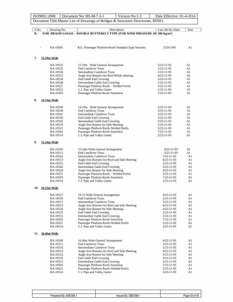
ISO9001:2008 Document No: BS-M-7.3-1 Version No:1.3 Date Effective: 01-4-2014
Document Title:Master List of Drawings of Bridges & Structures Directorate, RDSO.
Prepared By: ADE/SB-1 Issued By: DBS/SB-I Page 43 of 55
B. FOR BRAOD GAUGE – DOUBLE BUTTERFLY TYPE (FOR WIND PRESSURE OF 200 Kg/m2)
-
RA-10501
B.G. Passenger Platform Roofs Standard Type Sections
3/29-3-84
A1
7. 12.19m Wide
RA-10535 12.19m Wide General Arrangement 5/23-11-93 A1 RA-10532 End Cantilever Truss 2/23-11-93 A1
RA-10536 Intermediate Cantilever Truss 2/23-11-93 A1
RA-10533 Angle Iron Runners for Roof &Side sheeting 4/23-11-93 A1 RA-10534 End Gable End Covering 2/23-11-93 A1
RA-10538 Intermediate Gable End Covering 2/23-11-93 A1
RA-10521 Passenger Platform Roofs – Welded Purlin 5/23-11-93 A1 RA-10522 C.I. Pipe and Valley Gutter 2/23-11-93 A1
RA-10503 Passenger Platform Roofs Stanchion
7/23-11-93 A1
8. 14.33m Wide
RA-10540 14.33m Wide General Arrangement 2/23-11-93 A1 RA-10518 End Cantilever Truss 3/23-11-93 A1
RA-10541 Intermediate Cantilever Truss 2/23-11-93 A1
RA-10520 End Gable End Covering 3/23-11-93 A1 RA-10542 Intermediate Gable End Covering 2/23-11-93 A1
RA-10519 Angle Iron Runner for Side Sheeting 5/23-11-93 A1
RA-10521 Passenger Platform Roofs-Welded Purlin 5/23-11-93 A1 RA-10503 Passenger Platform Roofs Stanchion 7/23-11-93 A1
RA-10514 C.I. Pipe and Valley Gutter 2/23-11-93 A1
9. 15.24m Wide
RA-10543 15.24m Wide General Arrangement 4/23-11-93 A1 RA-10511 End Cantilever Truss 3/23-11-93 A1
RA-10541 Intermediate Cantilever Truss 2/23-11-93 A1
RA-10513 Angle Iron Runners for Roof and Side Sheeting 4/23-11-93 A1
RA-10525 End Gable End Covering 2/23-11-93 A1
RA-10542 Intermediate Gable End Covering 2/23-11-93 A1 RA-10524 Angle Iron Runner for Side Sheeting 4/23-11-93 A1
RA-10521 Passenger Platform Roofs – Welded Purlin 5/23-11-93 A1
RA-10503 Passenger Platform Roofs Stanchion 7/23-11-93 A1 RA-10514 C.I. Pipe and Valley Gutter
2/23-11-93 A1
10. 16.15m Wide
RA-10527 16.15 Wide General Arrangement 4/23-11-93 A1
RA-10510 End Cantilever Truss 2/23-11-93 A1 RA-10511 Intermediate Cantilever Truss 3/23-11-93 A1
RA-10513 Angle Iron Runners for Roof and Side Sheeting 4/23-11-93 A1
RA-10524 Angle Iron Runner for Side Sheeting . 4/23-11-93 A1 RA-10525 End Gable End Covering 2/23-11-93 A1
RA-10515 Intermediate Gable End Covering 3/23-11-93 A1
RA-10503 Passenger Platform Roofs Stanchion 7/23-11-93 A1
RA-10521 Passenger Platform Roofs-Welded Purlin 5/23-11-93 A1
RA-10514 C.I. Pipe and Valley Gutter 2/23-11-93 A1
11. 16.46m Wide
RA-10509 16.46m Wide General Arrangement 4/23-11-93 A1 RA-10511 End Cantilever Truss 3/23-11-93 A1
RA-10510 Intermediate Cantilever Truss 2/23-11-93 A1
RA-10513 Angle Iron Runners for Roof and Side Sheeting 4/23-11-93 A1 RA-10512 Angle Iron Runner for Side Sheeting. 3/23-11-93 A1
RA-10516 End Gable End Covering. 3/23-11-93 A1
RA-10515 Intermediate Gable End Covering 3/23-11-93 A1 RA-10503 Passenger Platform Roofs Stanchion 7/23-11-93 A1
RA-10521 Passenger Platform Roofs-Welded Purlin 5/23-11-93 A1
RA-10514 C.I. Pipe and Valley Gutter 2/23-11-93 A1
S.No. Drawing No. Description Last Alt.No./Date Size
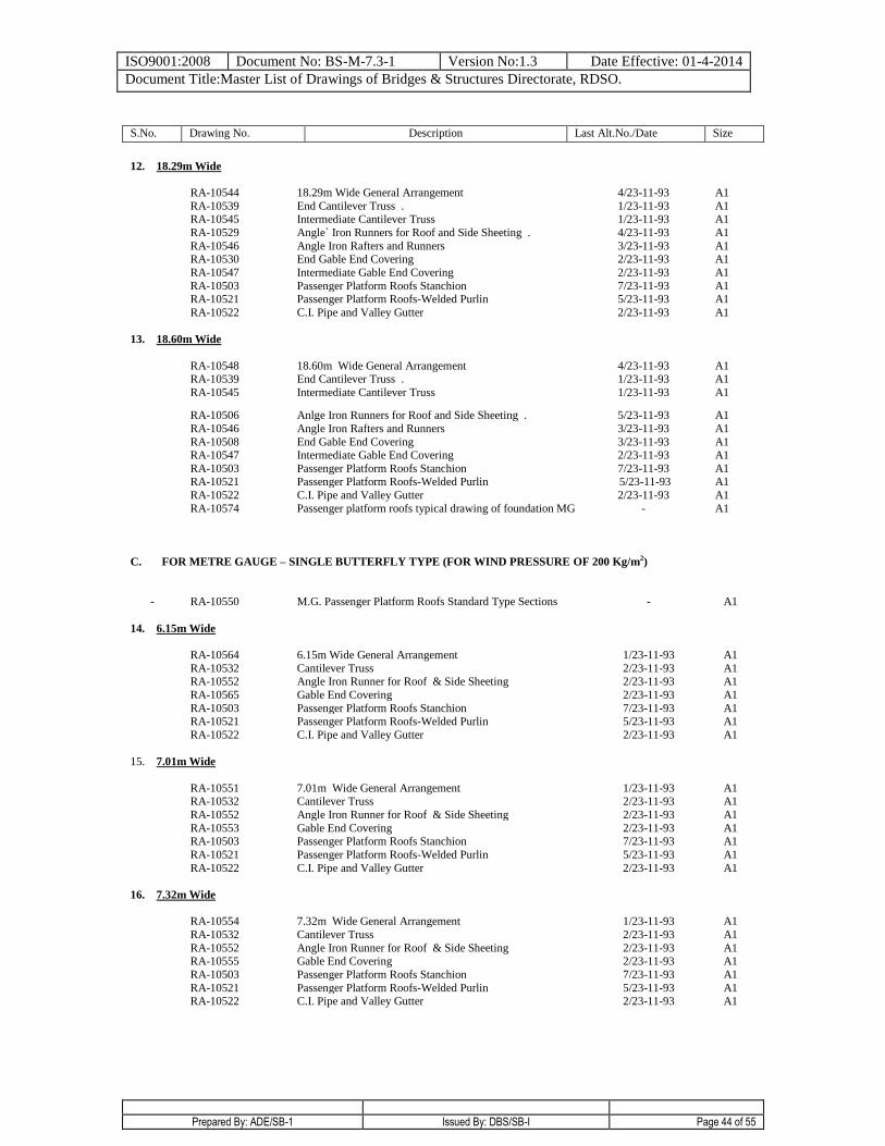
ISO9001:2008 Document No: BS-M-7.3-1 Version No:1.3 Date Effective: 01-4-2014
Document Title:Master List of Drawings of Bridges & Structures Directorate, RDSO.
Prepared By: ADE/SB-1 Issued By: DBS/SB-I Page 44 of 55
S.No. Drawing No. Description Last Alt.No./Date Size
12. 18.29m Wide
RA-10544 18.29m Wide General Arrangement 4/23-11-93 A1
RA-10539 End Cantilever Truss . 1/23-11-93 A1 RA-10545 Intermediate Cantilever Truss 1/23-11-93 A1
RA-10529 Angle` Iron Runners for Roof and Side Sheeting . 4/23-11-93 A1
RA-10546 Angle Iron Rafters and Runners 3/23-11-93 A1 RA-10530 End Gable End Covering 2/23-11-93 A1
RA-10547 Intermediate Gable End Covering 2/23-11-93 A1
RA-10503 Passenger Platform Roofs Stanchion 7/23-11-93 A1 RA-10521 Passenger Platform Roofs-Welded Purlin 5/23-11-93 A1
RA-10522 C.I. Pipe and Valley Gutter
2/23-11-93 A1
13. 18.60m Wide
RA-10548 18.60m Wide General Arrangement 4/23-11-93 A1 RA-10539 End Cantilever Truss . 1/23-11-93 A1
RA-10545 Intermediate Cantilever Truss 1/23-11-93 A1
RA-10506 Anlge Iron Runners for Roof and Side Sheeting . 5/23-11-93 A1
RA-10546 Angle Iron Rafters and Runners 3/23-11-93 A1
RA-10508 End Gable End Covering 3/23-11-93 A1 RA-10547 Intermediate Gable End Covering 2/23-11-93 A1
RA-10503 Passenger Platform Roofs Stanchion 7/23-11-93 A1 RA-10521 Passenger Platform Roofs-Welded Purlin 5/23-11-93 A1
RA-10522 C.I. Pipe and Valley Gutter 2/23-11-93 A1
RA-10574 Passenger platform roofs typical drawing of foundation MG - A1
C. FOR METRE GAUGE – SINGLE BUTTERFLY TYPE (FOR WIND PRESSURE OF 200 Kg/m2)
-
RA-10550
M.G. Passenger Platform Roofs Standard Type Sections
-
A1
14. 6.15m Wide
RA-10564 6.15m Wide General Arrangement 1/23-11-93 A1
RA-10532 Cantilever Truss 2/23-11-93 A1 RA-10552 Angle Iron Runner for Roof & Side Sheeting 2/23-11-93 A1
RA-10565 Gable End Covering 2/23-11-93 A1
RA-10503 Passenger Platform Roofs Stanchion 7/23-11-93 A1 RA-10521 Passenger Platform Roofs-Welded Purlin 5/23-11-93 A1
RA-10522 C.I. Pipe and Valley Gutter
2/23-11-93 A1
15. 7.01m Wide
RA-10551 7.01m Wide General Arrangement 1/23-11-93 A1 RA-10532 Cantilever Truss 2/23-11-93 A1
RA-10552 Angle Iron Runner for Roof & Side Sheeting 2/23-11-93 A1
RA-10553 Gable End Covering 2/23-11-93 A1 RA-10503 Passenger Platform Roofs Stanchion 7/23-11-93 A1
RA-10521 Passenger Platform Roofs-Welded Purlin 5/23-11-93 A1
RA-10522 C.I. Pipe and Valley Gutter
2/23-11-93 A1
16. 7.32m Wide
RA-10554 7.32m Wide General Arrangement 1/23-11-93 A1
RA-10532 Cantilever Truss 2/23-11-93 A1
RA-10552 Angle Iron Runner for Roof & Side Sheeting 2/23-11-93 A1 RA-10555 Gable End Covering 2/23-11-93 A1
RA-10503 Passenger Platform Roofs Stanchion 7/23-11-93 A1
RA-10521 Passenger Platform Roofs-Welded Purlin 5/23-11-93 A1 RA-10522 C.I. Pipe and Valley Gutter
2/23-11-93 A1
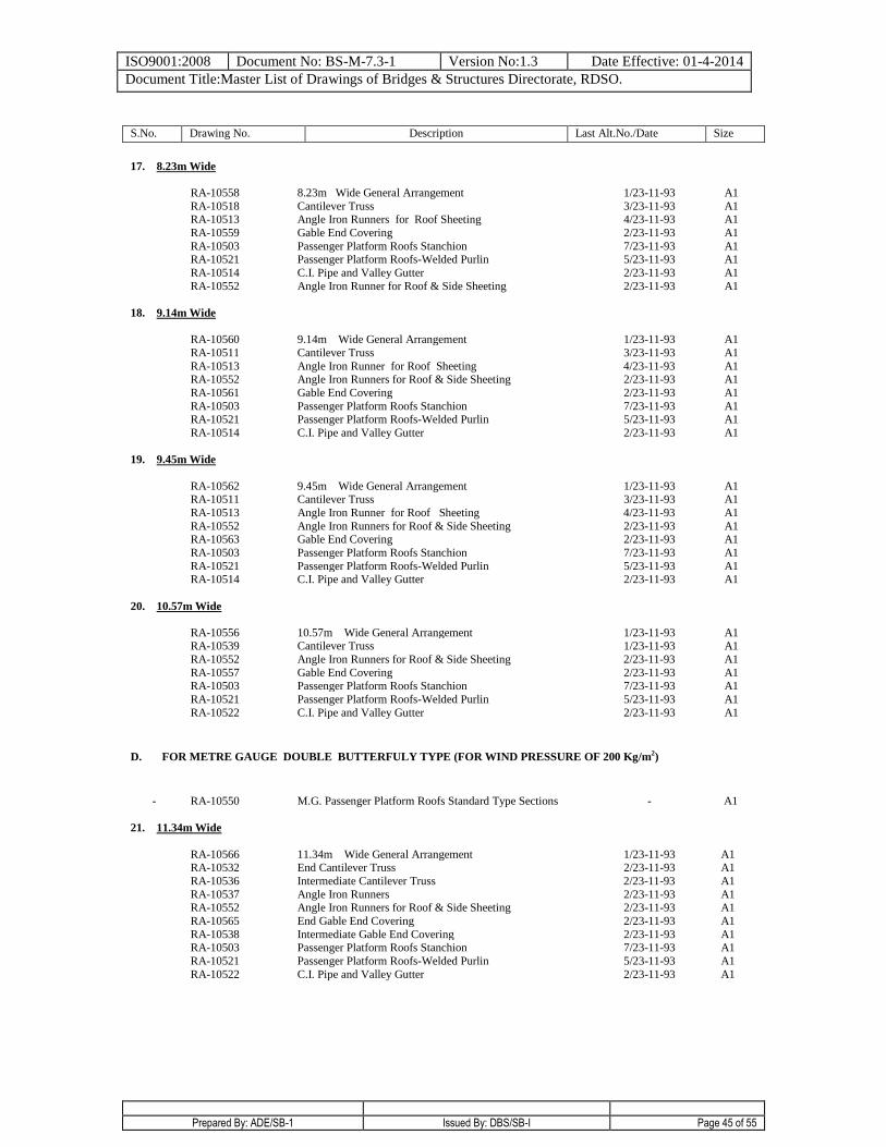
ISO9001:2008 Document No: BS-M-7.3-1 Version No:1.3 Date Effective: 01-4-2014
Document Title:Master List of Drawings of Bridges & Structures Directorate, RDSO.
Prepared By: ADE/SB-1 Issued By: DBS/SB-I Page 45 of 55
S.No. Drawing No. Description Last Alt.No./Date Size
17. 8.23m Wide
RA-10558 8.23m Wide General Arrangement 1/23-11-93 A1
RA-10518 Cantilever Truss 3/23-11-93 A1 RA-10513 Angle Iron Runners for Roof Sheeting 4/23-11-93 A1
RA-10559 Gable End Covering 2/23-11-93 A1
RA-10503 Passenger Platform Roofs Stanchion 7/23-11-93 A1 RA-10521 Passenger Platform Roofs-Welded Purlin 5/23-11-93 A1
RA-10514 C.I. Pipe and Valley Gutter 2/23-11-93 A1
RA-10552 Angle Iron Runner for Roof & Side Sheeting
2/23-11-93 A1
18. 9.14m Wide
RA-10560 9.14m Wide General Arrangement 1/23-11-93 A1
RA-10511 Cantilever Truss 3/23-11-93 A1
RA-10513 Angle Iron Runner for Roof Sheeting 4/23-11-93 A1 RA-10552 Angle Iron Runners for Roof & Side Sheeting 2/23-11-93 A1
RA-10561 Gable End Covering 2/23-11-93 A1
RA-10503 Passenger Platform Roofs Stanchion 7/23-11-93 A1 RA-10521 Passenger Platform Roofs-Welded Purlin 5/23-11-93 A1
RA-10514 C.I. Pipe and Valley Gutter 2/23-11-93 A1
19. 9.45m Wide
RA-10562 9.45m Wide General Arrangement 1/23-11-93 A1 RA-10511 Cantilever Truss 3/23-11-93 A1
RA-10513 Angle Iron Runner for Roof Sheeting 4/23-11-93 A1
RA-10552 Angle Iron Runners for Roof & Side Sheeting 2/23-11-93 A1 RA-10563 Gable End Covering 2/23-11-93 A1
RA-10503 Passenger Platform Roofs Stanchion 7/23-11-93 A1
RA-10521 Passenger Platform Roofs-Welded Purlin 5/23-11-93 A1 RA-10514 C.I. Pipe and Valley Gutter
2/23-11-93 A1
20. 10.57m Wide
RA-10556 10.57m Wide General Arrangement 1/23-11-93 A1 RA-10539 Cantilever Truss 1/23-11-93 A1
RA-10552 Angle Iron Runners for Roof & Side Sheeting 2/23-11-93 A1
RA-10557 Gable End Covering 2/23-11-93 A1 RA-10503 Passenger Platform Roofs Stanchion 7/23-11-93 A1
RA-10521 Passenger Platform Roofs-Welded Purlin 5/23-11-93 A1
RA-10522 C.I. Pipe and Valley Gutter
2/23-11-93 A1
D. FOR METRE GAUGE DOUBLE BUTTERFULY TYPE (FOR WIND PRESSURE OF 200 Kg/m2)
-
RA-10550
M.G. Passenger Platform Roofs Standard Type Sections
-
A1
21. 11.34m Wide
RA-10566 11.34m Wide General Arrangement 1/23-11-93 A1 RA-10532 End Cantilever Truss 2/23-11-93 A1
RA-10536 Intermediate Cantilever Truss 2/23-11-93 A1
RA-10537 Angle Iron Runners 2/23-11-93 A1 RA-10552 Angle Iron Runners for Roof & Side Sheeting 2/23-11-93 A1
RA-10565 End Gable End Covering 2/23-11-93 A1
RA-10538 Intermediate Gable End Covering 2/23-11-93 A1 RA-10503 Passenger Platform Roofs Stanchion 7/23-11-93 A1
RA-10521 Passenger Platform Roofs-Welded Purlin 5/23-11-93 A1
RA-10522 C.I. Pipe and Valley Gutter
2/23-11-93 A1
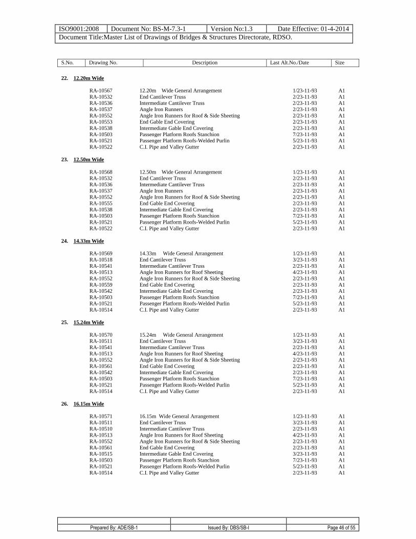
ISO9001:2008 Document No: BS-M-7.3-1 Version No:1.3 Date Effective: 01-4-2014
Document Title:Master List of Drawings of Bridges & Structures Directorate, RDSO.
Prepared By: ADE/SB-1 Issued By: DBS/SB-I Page 46 of 55
S.No. Drawing No. Description Last Alt.No./Date Size
22. 12.20m Wide
RA-10567 12.20m Wide General Arrangement 1/23-11-93 A1
RA-10532 End Cantilever Truss 2/23-11-93 A1 RA-10536 Intermediate Cantilever Truss 2/23-11-93 A1
RA-10537 Angle Iron Runners 2/23-11-93 A1
RA-10552 Angle Iron Runners for Roof & Side Sheeting 2/23-11-93 A1 RA-10553 End Gable End Covering 2/23-11-93 A1
RA-10538 Intermediate Gable End Covering 2/23-11-93 A1
RA-10503 Passenger Platform Roofs Stanchion 7/23-11-93 A1 RA-10521 Passenger Platform Roofs-Welded Purlin 5/23-11-93 A1
RA-10522 C.I. Pipe and Valley Gutter
2/23-11-93 A1
23. 12.50m Wide
RA-10568 12.50m Wide General Arrangement 1/23-11-93 A1 RA-10532 End Cantilever Truss 2/23-11-93 A1
RA-10536 Intermediate Cantilever Truss 2/23-11-93 A1
RA-10537 Angle Iron Runners 2/23-11-93 A1 RA-10552 Angle Iron Runners for Roof & Side Sheeting 2/23-11-93 A1
RA-10555 End Gable End Covering 2/23-11-93 A1
RA-10538 Intermediate Gable End Covering 2/23-11-93 A1 RA-10503 Passenger Platform Roofs Stanchion 7/23-11-93 A1
RA-10521 Passenger Platform Roofs-Welded Purlin 5/23-11-93 A1
RA-10522 C.I. Pipe and Valley Gutter
2/23-11-93 A1
24. 14.33m Wide
RA-10569 14.33m Wide General Arrangement 1/23-11-93 A1
RA-10518 End Cantilever Truss 3/23-11-93 A1
RA-10541 Intermediate Cantilever Truss 2/23-11-93 A1 RA-10513 Angle Iron Runners for Roof Sheeting 4/23-11-93 A1
RA-10552 Angle Iron Runners for Roof & Side Sheeting 2/23-11-93 A1
RA-10559 End Gable End Covering 2/23-11-93 A1 RA-10542 Intermediate Gable End Covering 2/23-11-93 A1
RA-10503 Passenger Platform Roofs Stanchion 7/23-11-93 A1 RA-10521 Passenger Platform Roofs-Welded Purlin 5/23-11-93 A1
RA-10514 C.I. Pipe and Valley Gutter 2/23-11-93 A1
25. 15.24m Wide
RA-10570 15.24m Wide General Arrangement 1/23-11-93 A1 RA-10511 End Cantilever Truss 3/23-11-93 A1
RA-10541 Intermediate Cantilever Truss 2/23-11-93 A1
RA-10513 Angle Iron Runners for Roof Sheeting 4/23-11-93 A1 RA-10552 Angle Iron Runners for Roof & Side Sheeting 2/23-11-93 A1
RA-10561 End Gable End Covering 2/23-11-93 A1
RA-10542 Intermediate Gable End Covering 2/23-11-93 A1 RA-10503 Passenger Platform Roofs Stanchion 7/23-11-93 A1
RA-10521 Passenger Platform Roofs-Welded Purlin 5/23-11-93 A1
RA-10514 C.I. Pipe and Valley Gutter
2/23-11-93 A1
26. 16.15m Wide
RA-10571 16.15m Wide General Arrangement 1/23-11-93 A1
RA-10511 End Cantilever Truss 3/23-11-93 A1
RA-10510 Intermediate Cantilever Truss 2/23-11-93 A1 RA-10513 Angle Iron Runners for Roof Sheeting 4/23-11-93 A1
RA-10552 Angle Iron Runners for Roof & Side Sheeting 2/23-11-93 A1
RA-10561 End Gable End Covering 2/23-11-93 A1 RA-10515 Intermediate Gable End Covering 3/23-11-93 A1
RA-10503 Passenger Platform Roofs Stanchion 7/23-11-93 A1
RA-10521 Passenger Platform Roofs-Welded Purlin 5/23-11-93 A1
RA-10514 C.I. Pipe and Valley Gutter
2/23-11-93 A1
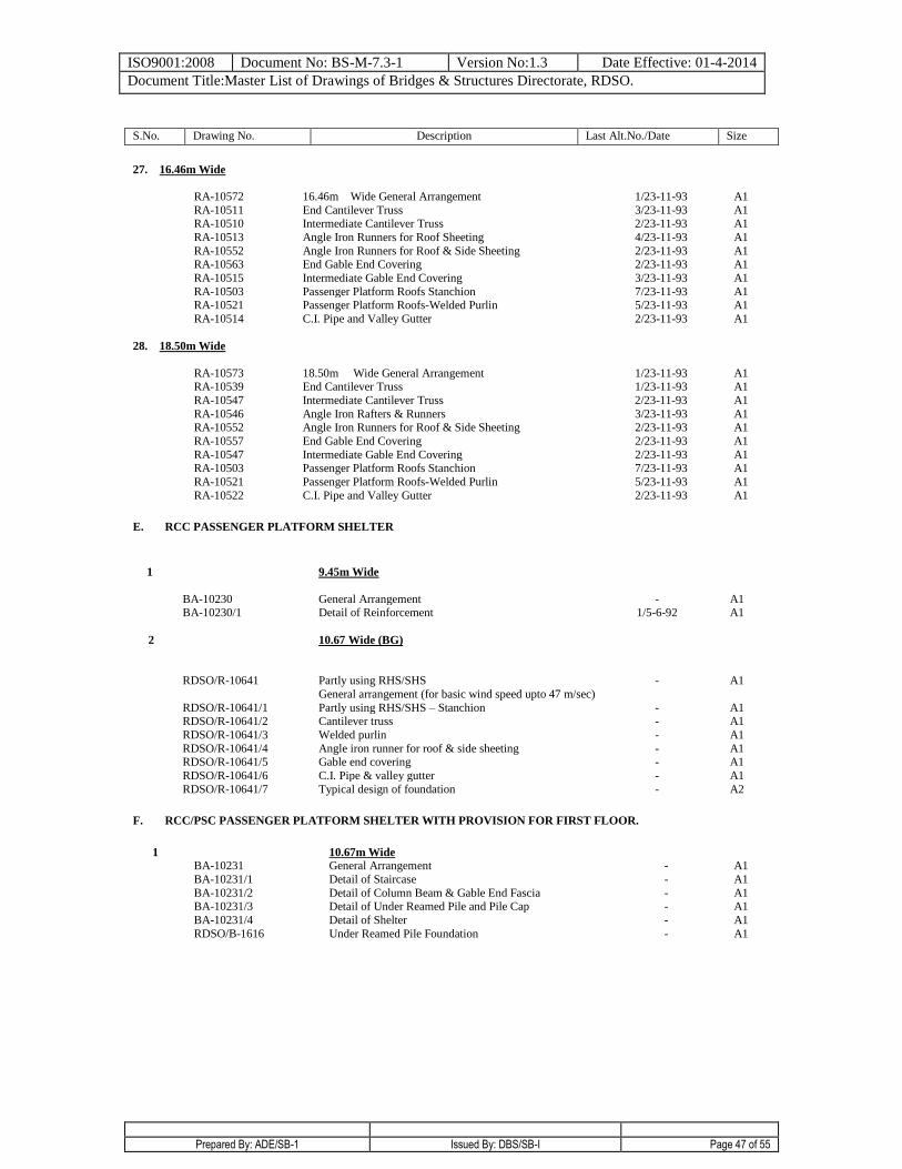
ISO9001:2008 Document No: BS-M-7.3-1 Version No:1.3 Date Effective: 01-4-2014
Document Title:Master List of Drawings of Bridges & Structures Directorate, RDSO.
Prepared By: ADE/SB-1 Issued By: DBS/SB-I Page 47 of 55
S.No. Drawing No. Description Last Alt.No./Date Size
27. 16.46m Wide
RA-10572 16.46m Wide General Arrangement 1/23-11-93 A1
RA-10511 End Cantilever Truss 3/23-11-93 A1 RA-10510 Intermediate Cantilever Truss 2/23-11-93 A1
RA-10513 Angle Iron Runners for Roof Sheeting 4/23-11-93 A1
RA-10552 Angle Iron Runners for Roof & Side Sheeting 2/23-11-93 A1 RA-10563 End Gable End Covering 2/23-11-93 A1
RA-10515 Intermediate Gable End Covering 3/23-11-93 A1
RA-10503 Passenger Platform Roofs Stanchion 7/23-11-93 A1 RA-10521 Passenger Platform Roofs-Welded Purlin 5/23-11-93 A1
RA-10514 C.I. Pipe and Valley Gutter
2/23-11-93 A1
28. 18.50m Wide
RA-10573 18.50m Wide General Arrangement 1/23-11-93 A1 RA-10539 End Cantilever Truss 1/23-11-93 A1
RA-10547 Intermediate Cantilever Truss 2/23-11-93 A1
RA-10546 Angle Iron Rafters & Runners 3/23-11-93 A1 RA-10552 Angle Iron Runners for Roof & Side Sheeting 2/23-11-93 A1
RA-10557 End Gable End Covering 2/23-11-93 A1
RA-10547 Intermediate Gable End Covering 2/23-11-93 A1 RA-10503 Passenger Platform Roofs Stanchion 7/23-11-93 A1
RA-10521 Passenger Platform Roofs-Welded Purlin 5/23-11-93 A1
RA-10522 C.I. Pipe and Valley Gutter 2/23-11-93 A1
E. RCC PASSENGER PLATFORM SHELTER
1
9.45m Wide
BA-10230 General Arrangement - A1 BA-10230/1 Detail of Reinforcement 1/5-6-92 A1
2
10.67 Wide (BG)
RDSO/R-10641 Partly using RHS/SHS
General arrangement (for basic wind speed upto 47 m/sec)
- A1
RDSO/R-10641/1 Partly using RHS/SHS – Stanchion - A1 RDSO/R-10641/2 Cantilever truss - A1
RDSO/R-10641/3 Welded purlin - A1
RDSO/R-10641/4 Angle iron runner for roof & side sheeting - A1 RDSO/R-10641/5 Gable end covering - A1
RDSO/R-10641/6 C.I. Pipe & valley gutter - A1
RDSO/R-10641/7 Typical design of foundation - A2
F. RCC/PSC PASSENGER PLATFORM SHELTER WITH PROVISION FOR FIRST FLOOR.
1 10.67m Wide BA-10231 General Arrangement - A1
BA-10231/1 Detail of Staircase - A1
BA-10231/2 Detail of Column Beam & Gable End Fascia - A1 BA-10231/3 Detail of Under Reamed Pile and Pile Cap - A1
BA-10231/4 Detail of Shelter - A1
RDSO/B-1616 Under Reamed Pile Foundation - A1
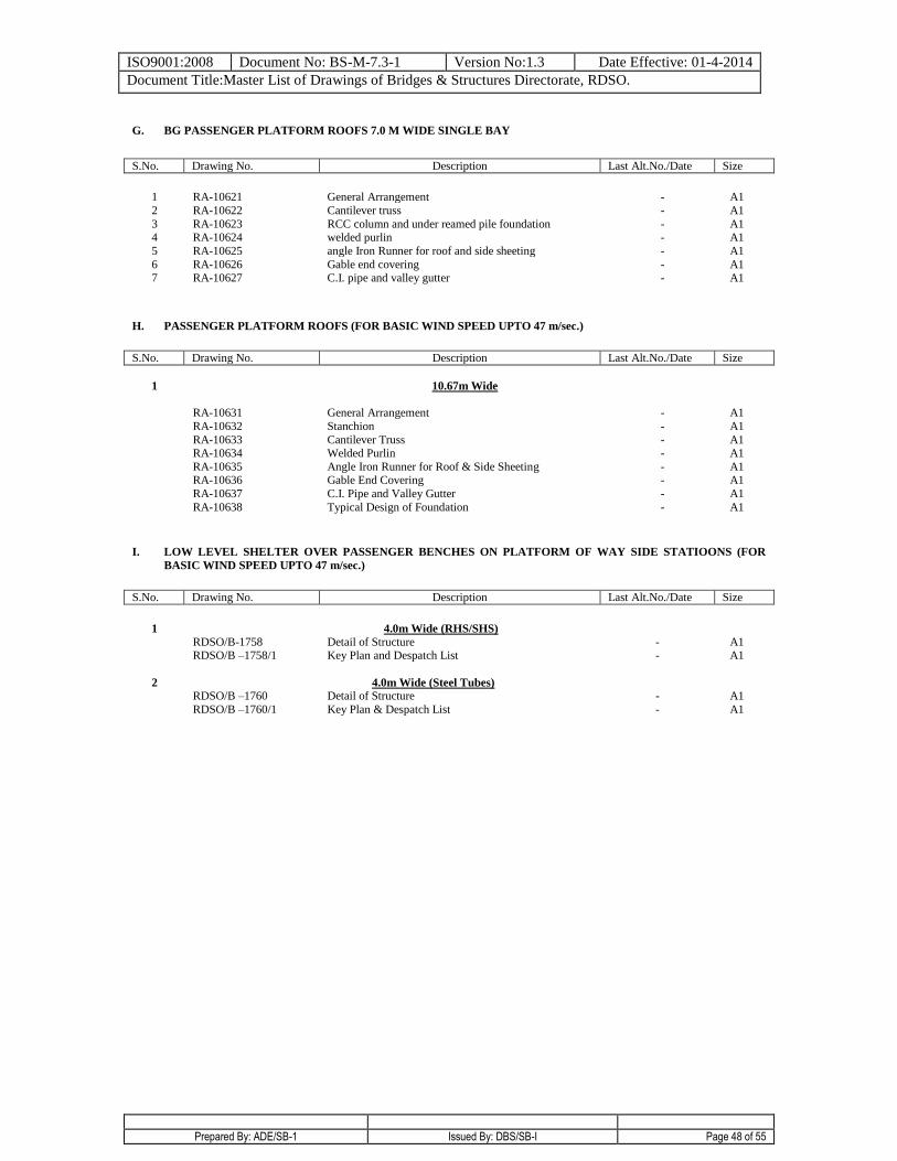
ISO9001:2008 Document No: BS-M-7.3-1 Version No:1.3 Date Effective: 01-4-2014
Document Title:Master List of Drawings of Bridges & Structures Directorate, RDSO.
Prepared By: ADE/SB-1 Issued By: DBS/SB-I Page 48 of 55
G. BG PASSENGER PLATFORM ROOFS 7.0 M WIDE SINGLE BAY
S.No. Drawing No. Description Last Alt.No./Date Size
1 RA-10621 General Arrangement - A1
2 RA-10622 Cantilever truss - A1
3 RA-10623 RCC column and under reamed pile foundation - A1 4 RA-10624 welded purlin - A1
5 RA-10625 angle Iron Runner for roof and side sheeting - A1
6 RA-10626 Gable end covering - A1 7 RA-10627 C.I. pipe and valley gutter - A1
H. PASSENGER PLATFORM ROOFS (FOR BASIC WIND SPEED UPTO 47 m/sec.)
S.No. Drawing No. Description Last Alt.No./Date Size
1 10.67m Wide
RA-10631 General Arrangement - A1
RA-10632 Stanchion - A1
RA-10633 Cantilever Truss - A1 RA-10634 Welded Purlin - A1
RA-10635 Angle Iron Runner for Roof & Side Sheeting - A1 RA-10636 Gable End Covering - A1
RA-10637 C.I. Pipe and Valley Gutter - A1
RA-10638 Typical Design of Foundation - A1
I. LOW LEVEL SHELTER OVER PASSENGER BENCHES ON PLATFORM OF WAY SIDE STATIOONS (FOR
BASIC WIND SPEED UPTO 47 m/sec.)
S.No. Drawing No. Description Last Alt.No./Date Size
1 4.0m Wide (RHS/SHS)
RDSO/B-1758 Detail of Structure - A1 RDSO/B –1758/1 Key Plan and Despatch List - A1
2 4.0m Wide (Steel Tubes)
RDSO/B –1760 Detail of Structure - A1
RDSO/B –1760/1 Key Plan & Despatch List - A1
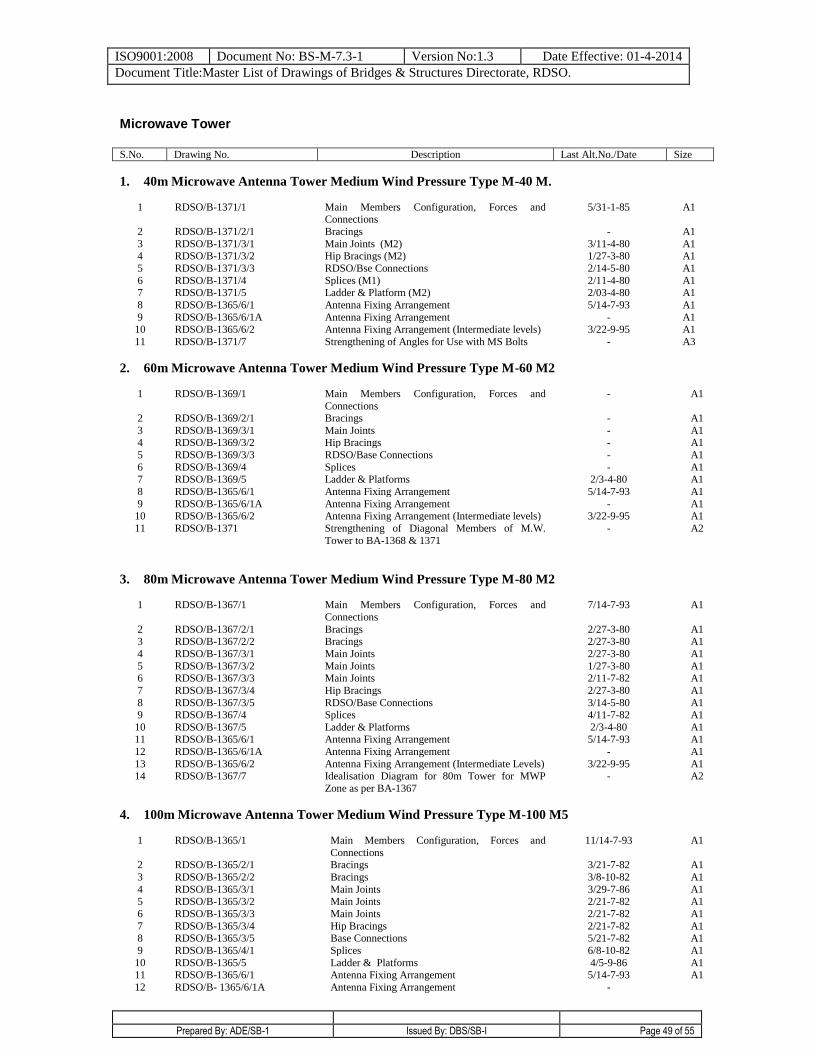
ISO9001:2008 Document No: BS-M-7.3-1 Version No:1.3 Date Effective: 01-4-2014
Document Title:Master List of Drawings of Bridges & Structures Directorate, RDSO.
Prepared By: ADE/SB-1 Issued By: DBS/SB-I Page 49 of 55
Microwave Tower
S.No. Drawing No. Description Last Alt.No./Date Size
1. 40m Microwave Antenna Tower Medium Wind Pressure Type M-40 M.
1 RDSO/B-1371/1 Main Members Configuration, Forces and Connections
5/31-1-85 A1
2 RDSO/B-1371/2/1 Bracings - A1
3 RDSO/B-1371/3/1 Main Joints (M2) 3/11-4-80 A1 4 RDSO/B-1371/3/2 Hip Bracings (M2) 1/27-3-80 A1
5 RDSO/B-1371/3/3 RDSO/Bse Connections 2/14-5-80 A1
6 RDSO/B-1371/4 Splices (M1) 2/11-4-80 A1 7 RDSO/B-1371/5 Ladder & Platform (M2) 2/03-4-80 A1
8 RDSO/B-1365/6/1 Antenna Fixing Arrangement 5/14-7-93 A1
9 RDSO/B-1365/6/1A Antenna Fixing Arrangement - A1 10 RDSO/B-1365/6/2 Antenna Fixing Arrangement (Intermediate levels) 3/22-9-95 A1
11 RDSO/B-1371/7 Strengthening of Angles for Use with MS Bolts
- A3
2. 60m Microwave Antenna Tower Medium Wind Pressure Type M-60 M2
1 RDSO/B-1369/1 Main Members Configuration, Forces and
Connections
- A1
2 RDSO/B-1369/2/1 Bracings - A1
3 RDSO/B-1369/3/1 Main Joints - A1 4 RDSO/B-1369/3/2 Hip Bracings - A1
5 RDSO/B-1369/3/3 RDSO/Base Connections - A1
6 RDSO/B-1369/4 Splices - A1 7 RDSO/B-1369/5 Ladder & Platforms 2/3-4-80 A1
8 RDSO/B-1365/6/1 Antenna Fixing Arrangement 5/14-7-93 A1
9 RDSO/B-1365/6/1A Antenna Fixing Arrangement - A1 10 RDSO/B-1365/6/2 Antenna Fixing Arrangement (Intermediate levels) 3/22-9-95 A1
11 RDSO/B-1371 Strengthening of Diagonal Members of M.W.
Tower to BA-1368 & 1371
- A2
3. 80m Microwave Antenna Tower Medium Wind Pressure Type M-80 M2
1 RDSO/B-1367/1 Main Members Configuration, Forces and
Connections
7/14-7-93 A1
2 RDSO/B-1367/2/1 Bracings 2/27-3-80 A1 3 RDSO/B-1367/2/2 Bracings 2/27-3-80 A1
4 RDSO/B-1367/3/1 Main Joints 2/27-3-80 A1
5 RDSO/B-1367/3/2 Main Joints 1/27-3-80 A1 6 RDSO/B-1367/3/3 Main Joints 2/11-7-82 A1
7 RDSO/B-1367/3/4 Hip Bracings 2/27-3-80 A1
8 RDSO/B-1367/3/5 RDSO/Base Connections 3/14-5-80 A1 9 RDSO/B-1367/4 Splices 4/11-7-82 A1
10 RDSO/B-1367/5 Ladder & Platforms 2/3-4-80 A1 11 RDSO/B-1365/6/1 Antenna Fixing Arrangement 5/14-7-93 A1
12 RDSO/B-1365/6/1A Antenna Fixing Arrangement - A1
13 RDSO/B-1365/6/2 Antenna Fixing Arrangement (Intermediate Levels) 3/22-9-95 A1
14 RDSO/B-1367/7 Idealisation Diagram for 80m Tower for MWP
Zone as per BA-1367
- A2
4. 100m Microwave Antenna Tower Medium Wind Pressure Type M-100 M5
1 RDSO/B-1365/1 Main Members Configuration, Forces and
Connections
11/14-7-93 A1
2 RDSO/B-1365/2/1 Bracings 3/21-7-82 A1
3 RDSO/B-1365/2/2 Bracings 3/8-10-82 A1
4 RDSO/B-1365/3/1 Main Joints 3/29-7-86 A1 5 RDSO/B-1365/3/2 Main Joints 2/21-7-82 A1
6 RDSO/B-1365/3/3 Main Joints 2/21-7-82 A1
7 RDSO/B-1365/3/4 Hip Bracings 2/21-7-82 A1 8 RDSO/B-1365/3/5 Base Connections 5/21-7-82 A1
9 RDSO/B-1365/4/1 Splices 6/8-10-82 A1
10 RDSO/B-1365/5 Ladder & Platforms 4/5-9-86 A1 11 RDSO/B-1365/6/1 Antenna Fixing Arrangement 5/14-7-93 A1
12 RDSO/B- 1365/6/1A Antenna Fixing Arrangement -
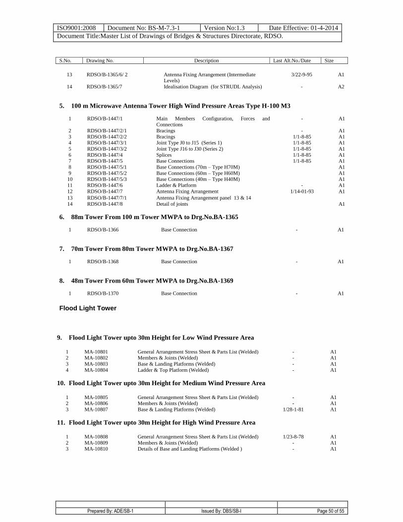
ISO9001:2008 Document No: BS-M-7.3-1 Version No:1.3 Date Effective: 01-4-2014
Document Title:Master List of Drawings of Bridges & Structures Directorate, RDSO.
Prepared By: ADE/SB-1 Issued By: DBS/SB-I Page 50 of 55
S.No. Drawing No. Description Last Alt.No./Date Size
13 RDSO/B-1365/6/ 2 Antenna Fixing Arrangement (Intermediate
Levels) 3/22-9-95 A1
14 RDSO/B-1365/7 Idealisation Diagram (for STRUDL Analysis)
- A2
5. 100 m Microwave Antenna Tower High Wind Pressure Areas Type H-100 M3
1 RDSO/B-1447/1 Main Members Configuration, Forces and Connections
- A1
2 RDSO/B-1447/2/1 Bracings - A1
3 RDSO/B-1447/2/2 Bracings 1/1-8-85 A1 4 RDSO/B-1447/3/1 Joint Type J0 to J15 (Series 1) 1/1-8-85 A1
5 RDSO/B-1447/3/2 Joint Type J16 to J30 (Series 2) 1/1-8-85 A1
6 RDSO/B-1447/4 Splices 1/1-8-85 A1 7 RDSO/B-1447/5 Base Connections 1/1-8-85 A1
8 RDSO/B-1447/5/1 Base Connections (70m – Type H70M) A1
9 RDSO/B-1447/5/2 Base Connections (60m – Type H60M) A1 10 RDSO/B-1447/5/3 Base Connections (40m – Type H40M) A1
11 RDSO/B-1447/6 Ladder & Platform - A1
12 RDSO/B-1447/7 Antenna Fixing Arrangement 1/14-01-93 A1
13 RDSO/B-1447/7/1 Antenna Fixing Arrangement panel 13 & 14
14 RDSO/B-1447/8 Detail of joints A1
6. 88m Tower From 100 m Tower MWPA to Drg.No.BA-1365
1 RDSO/B-1366 Base Connection
- A1
7. 70m Tower From 80m Tower MWPA to Drg.No.BA-1367
1 RDSO/B-1368 Base Connection - A1
8. 48m Tower From 60m Tower MWPA to Drg.No.BA-1369
1 RDSO/B-1370 Base Connection - A1
Flood Light Tower
9. Flood Light Tower upto 30m Height for Low Wind Pressure Area
1 MA-10801 General Arrangement Stress Sheet & Parts List (Welded) - A1 2 MA-10802 Members & Joints (Welded) - A1
3 MA-10803 Base & Landing Platforms (Welded) - A1
4 MA-10804 Ladder & Top Platform (Welded)
- A1
10. Flood Light Tower upto 30m Height for Medium Wind Pressure Area
1 MA-10805 General Arrangement Stress Sheet & Parts List (Welded) - A1 2 MA-10806 Members & Joints (Welded) - A1
3 MA-10807 Base & Landing Platforms (Welded)
1/28-1-81 A1
11. Flood Light Tower upto 30m Height for High Wind Pressure Area
1 MA-10808 General Arrangement Stress Sheet & Parts List (Welded) 1/23-8-78 A1
2 MA-10809 Members & Joints (Welded) - A1 3 MA-10810 Details of Base and Landing Platforms (Welded ) - A1
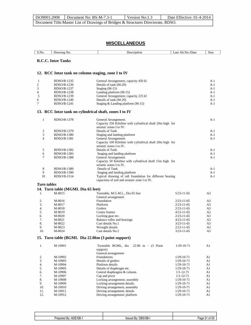
ISO9001:2008 Document No: BS-M-7.3-1 Version No:1.3 Date Effective: 01-4-2014
Document Title:Master List of Drawings of Bridges & Structures Directorate, RDSO.
Prepared By: ADE/SB-1 Issued By: DBS/SB-I Page 51 of 55
MISCELLANEOUS
R.C.C. Intze Tanks
12. RCC Intze tank on column staging, zone I to IV 1 RDSO/B-1235 General Arrangement, capacity 450 kl A-1
2 RDSO/B-1236 Details of tank (M-20) A-1
3 RDSO/B-1237 Staging (M-15) A-1 4 RDSO/B-1238 Landing platform (M-15) A-1
5 RDSO/B-1239 General Arrangement, capacity 225 kl A-1
6 RDSO/B-1240 Details of tank (M-20) A-1
7 RDSO/B-1241 Staging & Landing platform (M-15) A-1
13. RCC Intze tank on cylindrical shaft, zones I to IV
1 RDSO/B-1378 General Arrangement.
Capacity 250 Kiloliter with cylindrical shaft 20m high for seismic zones I to IV.
A-1
2 RDSO/B-1379 Details of Tank A-1
3 RDSO/B-1380 Staging and landing platform A-1 4 RDSO/B-1381 General Arrangement.
Capacity 100 Kiloliter with cylindrical shaft 20m high for
seismic zones I to IV.
A-1
5 RDSO/B-1382 Details of Tank A-1
6 RDSO/B-1383 Staging and landing platform A-1
7 RDSO/B-1388 General Arrangement. Capacity 50 Kiloliter with cylindrical shaft 15m high for
seismic zones I to IV.
A-1
8 RDSO/B-1389 Details of Tank A-1
9 RDSO/B-1390 Staging and landing platform A-1
10 RDSO/B-1514 Typical drawing of raft foundation for different bearing
capacities of soil and seismic zone I to IV.
A-1
Turn tables
14. Turn table (MGML Dia 65 feet) 1. M-8015 Turntable, M.G.M.L., Dia 65 feet
General arrangement
5/23-11-65 A3
2. M-8016 Foundation 2/23-11-65 A3
3. M-8017 Platform 2/23-11-65 A3
4. M-8018 Girders 2/23-11-65 A3 5. M-8019 Centre frames 4/23-11-65 A3
6. M-8020 Locking gear etc. 2/23-11-65 A3
7. M-8021 Balance roller and bearings 4/23-11-65 A3 8. M-8022 Cast details No.1 3/23-11-65 A3
9. M-8023 Wrought details 2/23-11-65 A3
10. M-8024 Cast details No.2 3/23-11-65 A3
15. Turn table (BGML Dia 22.86m (3 point support)
1. M-10901 Turntable BGML, dia 22.86 m – (3 Point support)
General arrangement
1/29-10-71 A1
2. M-10902 Foundations 1/29-10-71 A1 3. M-10903 Details of girders 1/29-10-71 A1
4. M-10904 Platform details 1/29-10-71 A1
5. M-10905 Details of diaphragm etc. 1/29-10-71 A1 6. M-10906 Central diaphragms & column 1/1-12-71 A1
7. M-10907 Cap and pivot 1/1-12-71 A1
8. M-10908 Locking arrangement; assembly 1/29-10-71 A1 9. M-10909 Locking arrangement details. 1/29-10-71 A1
10. M-10910 Driving arrangement; assembly 1/29-10-71 A1
11. M-10911 Driving arrangement; details 1/29-10-71 A1 12. M-10912 Driving arrangement; platform 1/29-10-71 A1
S.No. Drawing No. Description Last Alt.No./Date Size
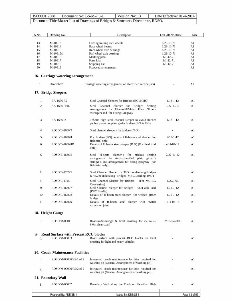
ISO9001:2008 Document No: BS-M-7.3-1 Version No:1.3 Date Effective: 01-4-2014
Document Title:Master List of Drawings of Bridges & Structures Directorate, RDSO.
Prepared By: ADE/SB-1 Issued By: DBS/SB-I Page 52 of 55
S.No. Drawing No. Description Last Alt.No./Date Size
13. M-10913 Driving trailing race wheels 1/29-10-71 A1 14. M-10914 Race wheel beams 1/29-10-71 A1
15. M-10915 Race wheel axle bearings 1/29-10-71 A1
16. M-10915/1 Rail wheel axle bearings 1/29-10-71 A1 17. M-10916 Marking plan 1/1-12-71 A1
18. M-10917 Parts List 1/1-12-71 A1
19. M-10918 Shipping list 1/1-12-71 A1 20. M-10919 Proposed arrangement A1
16. Carriage watering arrangement
1 HA-10602 Carriage watering arrangement on electrified section(BG) - A1
17. Bridge Sleepers
1 BA-1636 R2 Steel Channel Sleepers for Bridges (BG & MG) 1/13-1-12 A1
2 BA-1636 /1/R2 Steel Channel Sleeper for Bridges Seating
Arrangement for Rivetted/Welded Plate Girders
/Stringers and for Fixing Gangway
1/27-11/12 A1
3 BA-1636 /2 175mm high steel channel sleeper to avoid thicker pacing plates on plate girder bridges (BG & MG)
1/13-1-12 A1
4 RDSO/B-1636/3 Steel channel sleepers for bridges (N.G.) - A1
5
6
RDSO/B-1636/4
RDSO/B-1636/4R
For bridges (BG) details of H-beam steel sleeper for
field trial only. Details of H beam steel sleeper (B.G) (For field trial
only)
2/13-1-12
-/14-04-14
A1
A1
6 RDSO/B-1636/5 Steel H-beam sleeper’s for bridges seating
arrangement for rivetted/welded plate girder’s
stringer’s and arrangement for fixing gangway (For field trial only)
2/27-11-12 A1
7. RDSO/B-1739/R Steel Channel Sleeper for 30.5m underslung bridges
& 45.7m underslung Bridges (MBG Loading-1987)
A1
8. RDSO/B-1745 Steel Channel Sleeper for Bridges (For MG-BG
Conversion)
1/22/7/94 A1
9 RDSO/B-1636/7 Steel Channel Sleeper for Bridges 32.5t axle load
(DFC Loadig)
1/13-1-12 A1
10 RDSO/B-1636/8 Details of H-beam steel sleeper for welded girder bridge.
1/13-1-12 A1
11 RDSO/B-1636/9 Details of H-beam steel sleeper with switch
expansion joint.
-/14-04-14 A1
18. Height Gauge
1 RDSO/M-0001 Road-under-bridge & level crossing for (5.5m &
8.0m clear span)
2/01-05-2006 A1
19. Road Surface with Precast RCC blocks
1 RDSO/M-00003 Road surface with precast RCC blocks on level
crossing for light and heavy vehicles
- A1
20. Coach Maintenance Facilities
1 RDSO/M-00006/R2/1 of 2 Integrated coach maintenance facilities required for
washing pit (General Arrangement of washing pit)
- A1
2. RDSO/M-00006/R2/2 of 2 Integrated coach maintenance facilities required for washing pit (General Arrangement of washing pit)
- A1
21. Boundary Wall
1. RDSO/M-00007 Boundary Wall along the Track on Identified High - A1
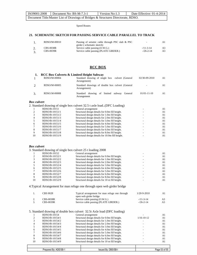
ISO9001:2008 Document No: BS-M-7.3-1 Version No:1.3 Date Effective: 01-4-2014
Document Title:Master List of Drawings of Bridges & Structures Directorate, RDSO.
Prepared By: ADE/SB-1 Issued By: DBS/SB-I Page 53 of 55
Speed Routes
21. SCHEMATIC SKETCH FOR PASSING SERVICE CABLE PARALLEL TO TRACK
1. RDSO/M-00010 Passing of seismic cable through PSC slab & PSC girder ( schematic sketch)
- A1
2.
3.
CBS-0038R
CBS-0039R
Service cable passing (O.W.G.)
Service cable passing (PLATE GIRDER.)
-/11-3-14
-/26-2-14
A3
A3
RCC BOX
1. RCC Box Culverts & Limited Height Subway
1 RDSO/M-00004 Standard drawing of single box culvert (General
Arrangement)
02/30-09-2010 A1
2 RDSO/M-00005 Standard drawings of double box culvert (General Arrangement)
- A1
3. RDSO.M-00008 Standard drawing of limited subway General Arrangement
01/01-11-10 A1
Box culvert
2. Standard drawing of single box culvert 32.5 t axle load..(DFC Loading) 1 RDSO/B-10151 General arrangement - A1
2 RDSO/B-10151/1 Structural design details for 0.0m fill height. - A1
3 RDSO/B-10151/2 Structural design details for 1.0m fill height. - A1 4 RDSO/B-10151/3 Structural design details for 2.0m fill height. - A1
5 RDSO/B-10151/4 Structural design details for 3.0m fill height. - A1
6 RDSO/B-10151/5 Structural design details for 4.0m fill height. - A1 7 RDSO/B-10151/6 Structural design details for 5.0m fill height. - A1
8 RDSO/B-10151/7 Structural design details for 6.0m fill height. - A1
9 RDSO/B-10151/8 Structural design details for 8.0m fill height. - A1
10 RDSO/B-10151/9 Structural design details for 10.0m fill height. - A1
Box culvert
3. Standard drawing of single box culvert 25 t loading 2008 1 RDSO/B-10152 General arrangement - A1
2 RDSO/B-10152/1 Structural design details for 0.0m fill height. - A1
3 RDSO/B-10152/2 Structural design details for 1.0m fill height. - A1 4 RDSO/B-10152/3 Structural design details for 2.0m fill height. - A1
5 RDSO/B-10152/4 Structural design details for 3.0m fill height. - A1
6 RDSO/B-10152/5 Structural design details for 4.0m fill height. - A1 7 RDSO/B-10152/6 Structural design details for 5.0m fill height. - A1
8 RDSO/B-10152/7 Structural design details for 6.0m fill height. - A1
9 RDSO/B-10152/8 Structural design details for 8.0m fill height. - A1 10 RDSO/B-10152/9 Structural design details for 10 m fill height. - A1
4.Typical Arrangement for man refuge one through open web girder bridge
1.
2. 3.
CBS 0028
CBS-0038R CBS-0039R
Typical arrangement for man refuge one through
open web girder bridge
Service cable passing (O.W.G.) Service cable passing (PLATE GIRDER.)
1/20-9-2010
-/11-3-14 -/26-2-14
A1
A3 A3
5. Standard drawing of double box culvert 32.5t Axle load (DFC loading) 1 RDSO/B-10154 General arrangement - A1
2 RDSO/B-10154/1 Structural design details for 0.0m fill height. 1/16-10-12 A1 3 RDSO/B-10154/2 Structural design details for 1.0m fill height. - A1
4 RDSO/B-10154/3 Structural design details for 2.0m fill height. - A1
5 RDSO/B-10154/4 Structural design details for 3.0m fill height. - A1 6 RDSO/B-10154/5 Structural design details for 4.0m fill height. - A1
7 RDSO/B-10154/6 Structural design details for 5.0m fill height. - A1
8 RDSO/B-10154/7 Structural design details for 6.0m fill height. - A1 9 RDSO/B-10154/8 Structural design details for 8.0m fill height. - A1
10 RDSO/B-10154/9 Structural design details for 10 m fill height. - A1
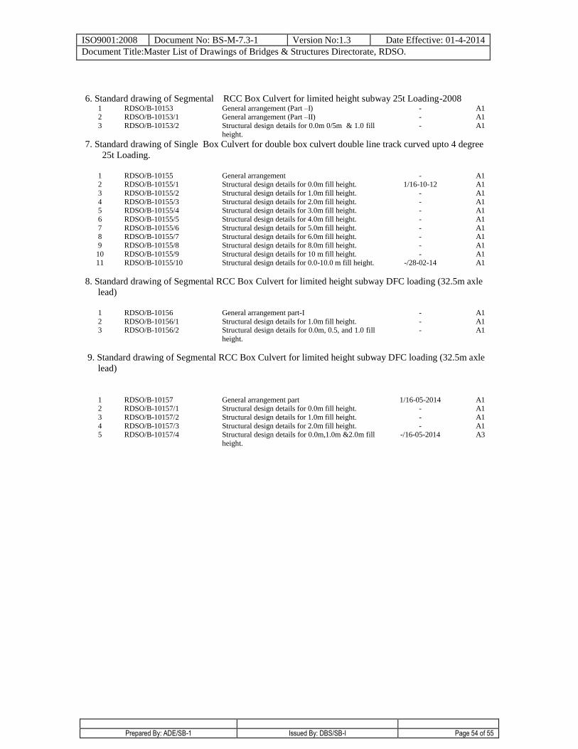
ISO9001:2008 Document No: BS-M-7.3-1 Version No:1.3 Date Effective: 01-4-2014
Document Title:Master List of Drawings of Bridges & Structures Directorate, RDSO.
Prepared By: ADE/SB-1 Issued By: DBS/SB-I Page 54 of 55
6. Standard drawing of Segmental RCC Box Culvert for limited height subway 25t Loading-2008 1 RDSO/B-10153 General arrangement (Part –I) - A1 2 RDSO/B-10153/1 General arrangement (Part –II) - A1
3 RDSO/B-10153/2 Structural design details for 0.0m 0/5m & 1.0 fill
height.
- A1
7. Standard drawing of Single Box Culvert for double box culvert double line track curved upto 4 degree
25t Loading.
1 RDSO/B-10155 General arrangement - A1 2 RDSO/B-10155/1 Structural design details for 0.0m fill height. 1/16-10-12 A1
3 RDSO/B-10155/2 Structural design details for 1.0m fill height. - A1
4 RDSO/B-10155/3 Structural design details for 2.0m fill height. - A1 5 RDSO/B-10155/4 Structural design details for 3.0m fill height. - A1
6 RDSO/B-10155/5 Structural design details for 4.0m fill height. - A1
7 RDSO/B-10155/6 Structural design details for 5.0m fill height. - A1
8 RDSO/B-10155/7 Structural design details for 6.0m fill height. - A1
9 RDSO/B-10155/8 Structural design details for 8.0m fill height. - A1
10 11
RDSO/B-10155/9 RDSO/B-10155/10
Structural design details for 10 m fill height. Structural design details for 0.0-10.0 m fill height.
- -/28-02-14
A1 A1
8. Standard drawing of Segmental RCC Box Culvert for limited height subway DFC loading (32.5m axle
lead)
1 RDSO/B-10156 General arrangement part-I - A1
2 RDSO/B-10156/1 Structural design details for 1.0m fill height. - A1 3 RDSO/B-10156/2 Structural design details for 0.0m, 0.5, and 1.0 fill
height.
- A1
9. Standard drawing of Segmental RCC Box Culvert for limited height subway DFC loading (32.5m axle
lead)
1 RDSO/B-10157 General arrangement part 1/16-05-2014 A1 2
3
RDSO/B-10157/1
RDSO/B-10157/2
Structural design details for 0.0m fill height.
Structural design details for 1.0m fill height.
-
-
A1
A1
4 5
RDSO/B-10157/3 RDSO/B-10157/4
Structural design details for 2.0m fill height. Structural design details for 0.0m,1.0m &2.0m fill
height.
- -/16-05-2014
A1 A3
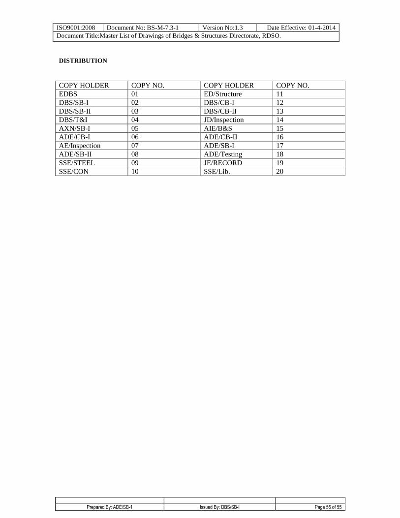
ISO9001:2008 Document No: BS-M-7.3-1 Version No:1.3 Date Effective: 01-4-2014
Document Title:Master List of Drawings of Bridges & Structures Directorate, RDSO.
Prepared By: ADE/SB-1 Issued By: DBS/SB-I Page 55 of 55
DISTRIBUTION
COPY HOLDER COPY NO. COPY HOLDER COPY NO.
EDBS 01 ED/Structure 11
DBS/SB-I 02 DBS/CB-I 12
DBS/SB-II 03 DBS/CB-II 13
DBS/T&I 04 JD/Inspection 14
AXN/SB-I 05 AIE/B&S 15
ADE/CB-I 06 ADE/CB-II 16
AE/Inspection 07 ADE/SB-I 17
ADE/SB-II 08 ADE/Testing 18
SSE/STEEL 09 JE/RECORD 19
SSE/CON 10 SSE/Lib. 20
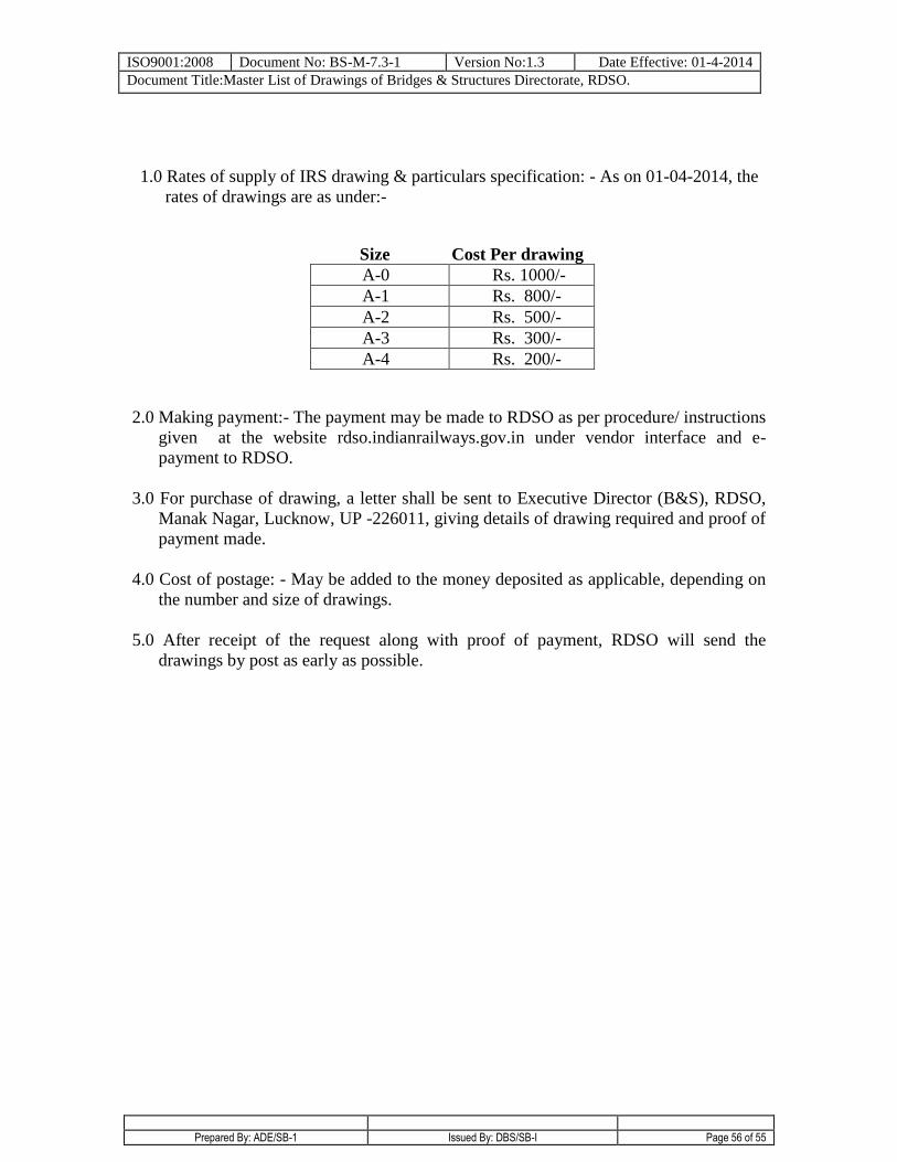
ISO9001:2008 Document No: BS-M-7.3-1 Version No:1.3 Date Effective: 01-4-2014
Document Title:Master List of Drawings of Bridges & Structures Directorate, RDSO.
Prepared By: ADE/SB-1 Issued By: DBS/SB-I Page 56 of 55
1.0 Rates of supply of IRS drawing & particulars specification: - As on 01-04-2014, the
rates of drawings are as under:-
Size Cost Per drawing
A-0 Rs. 1000/-
A-1 Rs. 800/-
A-2 Rs. 500/-
A-3 Rs. 300/-
A-4 Rs. 200/-
2.0 Making payment:- The payment may be made to RDSO as per procedure/ instructions
given at the website rdso.indianrailways.gov.in under vendor interface and e-
payment to RDSO.
3.0 For purchase of drawing, a letter shall be sent to Executive Director (B&S), RDSO,
Manak Nagar, Lucknow, UP -226011, giving details of drawing required and proof of
payment made.
4.0 Cost of postage: - May be added to the money deposited as applicable, depending on
the number and size of drawings.
5.0 After receipt of the request along with proof of payment, RDSO will send the
drawings by post as early as possible.