Embed Size (px)
Citation preview

2014 Subcommittee on Bridges and Structures Annual Meeting
Columbus, Ohio
General Session Agenda
Wednesday, June 25 - 1:00 pm to 5:00 pm
Welcome by Chairman and Host State of Ohio
Service Resolutions and Remarks by Chairman, and Roll Call by Secretary
FHWA Update – Joey Hartmann
AASHTOWare Bridge Products Update – Tim Armbrecht & Mike Johnson
Refined Gusset Plate Capacity – John Kulicki & Edward Wasserman
Break
T-18 Bridge Management Ballot Items – Matt Farrar
Developing Reliability Based Bridge Inspection Practices (NCHRP 12-82) – Glenn Washer
T-15 Substructures & Retaining Walls Ballot Items – Jawdat Siddiqi & Tony Allen
Thursday, June 26 - 8:00 am to 5:00 pm
Wisconsin’s Interstate 43 Leo Frigo Bridge Emergency: The Failure and the Fix – Scot Becker
T-14 Steel Ballot Items – Greg Perfetti
Long Term Bridge Program Update – Sue Lane
Break
T-13 Culverts Ballot Items– Gregory Bailey
Overview LRFD Specifications for Structural Supports for Highway Signs, Luminaires, and Traffic Signals –
Norm McDonald & Jay Puckett
T-12 Structural Supports Ballot Item – Norm McDonald
2014 NCHRP Bridge and Structure Research Updates – Waseem Dekalbab

T-11 Research Update Ballot Item – Nancy Daubenberger
FHWA Research and Technology Update – Ian Friedland
Lunch Break
TSP2/Bridge-2014 Update – Dave Juntunen
Reorganization of Section 5, Concrete Design of the LRFD Design Specifications – Loren Risch and John
Kulicki
T-10 Concrete Design Ballot Items – Loren Risch
Stan Musial Veteran’s Memorial Bridge – Dennis Heckman
Break
AASHTO Update – King Gee
T-7 Guardrail & Bridge Rail Ballot Items – Tim Keller
NCHRP Scan 12-01 – Advances in State DOT Superload Permit Process and Practices – Matt Farrar
T-5 Loads & Load Distribution Ballot Items – Susan Hida
Accelerated Bridge Construction University Transportation Center – Mary Lou Ralls
T-3 Seismic Ballot Items – Richard Pratt
SHRP2 Call for Implementation of Bridge Products – Matt DeMarco
Editorials – John Kulicki
Announcement of 2015 SCOBS in Saratoga Springs, NY – Richard Marchione
Closing – Gregg Fredrick

NAME:
STATE:
SUBJECT: AASHTO Annual Subcommittee on Bridges and Structures Meeting; Columbus, Ohio; June 22 – 26, 2014
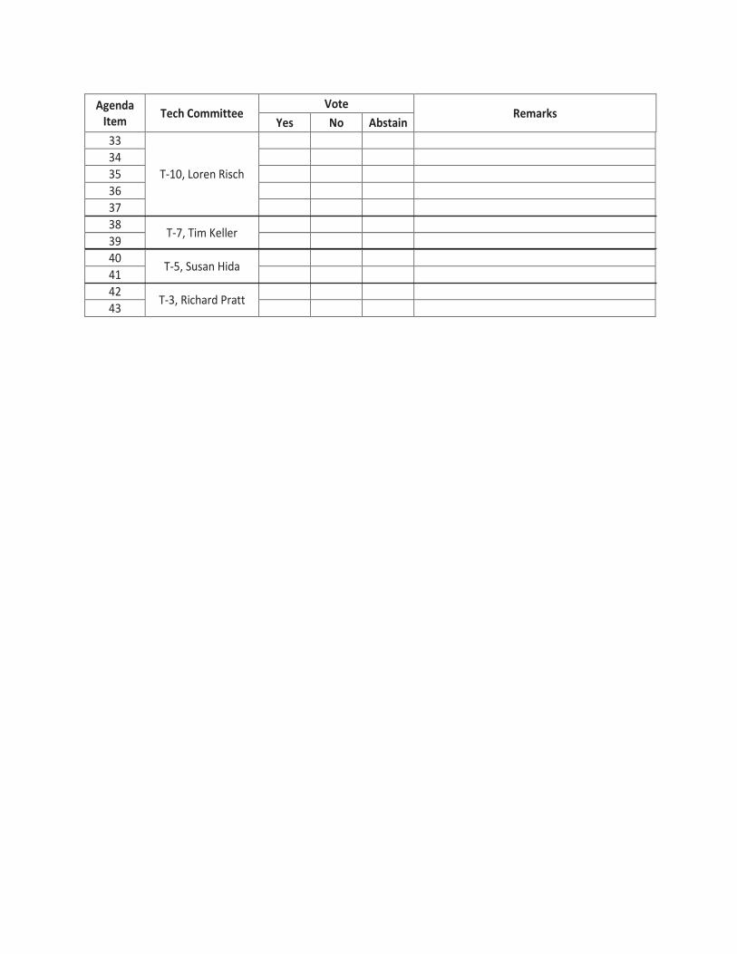
Agenda Item Tech Committee
Vote Remarks
Yes No Abstain 1
T-18, Matt Farrar
2 3 4 5 6 7 8 9
10 11 12
T-15, Jawdat Siddiqi & Tony Allen
13 14 15 16 17 18 19 20
T-14, Greg Perfetti
21 22 23 24 25 26 27 28 29 30 T-13, Gregory Bailey
31 T-12, Norm McDonald
32 T-11, Nancy Daubenberger
33
T-10, Loren Risch
34 35 36 37 38 T-7, Tim Keller 39 40 T-5, Susan Hida 41 42 T-3, Richard Pratt 43
NAME:
STATE:
SUBJECT: AASHTO Annual Subcommittee on Bridges and Structures Meeting; Columbus, Ohio; June 22 – 26, 2014
Agenda Item Tech Committee
Vote Remarks
Yes No Abstain 1
T-18, Matt Farrar
2 3 4 5 6 7 8 9
10 11 12
T-15, Jawdat Siddiqi & Tony Allen
13 14 15 16 17 18 19 20
T-14, Greg Perfetti
21 22 23 24 25 26 27 28 29 30 T-13, Gregory Bailey
31 T-12, Norm McDonald
32 T-11, Nancy Daubenberger
33
T-10, Loren Risch
34 35 36 37 38 T-7, Tim Keller 39 40 T-5, Susan Hida 41 42 T-3, Richard Pratt 43

i
2014 AASHTO BRIDGE SUBCOMMITTEE MEETINGTABLE OF CONTENTS
(As of May 20, 2014)
(Note: Agenda items for presentations are marked with alphabetical entries; those which are candidates as ballot items are sequentially numbered)
ItemNo. Item Page
Technical Committee Meetings
Main Meeting Schedule
A Welcome by Chairman and Host State of Ohio
B Service Resolutions and Remarks by Chairman, and Roll Call by Secretary
C FHWA Update – Joey Hartmann
D AASHTOWare Bridge Products Update – Tim Armbrecht and Mike Johnson
E Refined Gusset Plate Capacity – John Kulicki and Edward Wasserman
1 T-18 Committee (Bridge Management, Evaluation and Rehabilitation) – The Manual for Bridge Evaluation: Section 6, Articles 6A.2.3.2, C6A.2.3.2, 6B.6.2.2, C6B.6.2.2 (T18-1)
1
2 T-18 Committee (Bridge Management, Evaluation and Rehabilitation) – The Manual for Bridge Evaluation: Section 6, Article C6A.6.8, Appendices I6A and A (T18-3)
4
3 T-18 Committee (Bridge Management, Evaluation and Rehabilitation) – The Manual for Bridge Evaluation: Section 6, Article C6A.4.4.2.1b (T18-4)
10
4 T-18 Committee (Bridge Management, Evaluation and Rehabilitation) – The Manual for Bridge Evaluation: Section 6, Articles 6A.5.8 and 6B.5.2.4.3 (T18-5)
12
5 T-18 Committee (Bridge Management, Evaluation and Rehabilitation) – The Manual for Bridge Evaluation: Section 6, Articles 6A.6.12.6 and 6A.6.12.6.11 (T18-7)
15
6 T-18 Committee (Bridge Management, Evaluation and Rehabilitation) – The Manual for Bridge Evaluation: Section 7, Various Articles (T18-8)
27
7 T-18 Committee (Bridge Management, Evaluation and Rehabilitation) – The Manual for Bridge Evaluation: Section 6, Appendix A, Example A1 (T18-9)
48
ii
ItemNo. Item Page
8 T-18 Committee (Bridge Management, Evaluation and Rehabilitation) – AASHTO Manual for Bridge Element Inspection: Subsection 3.1.1 (T-18-10)
54
9 T-18 Committee (Bridge Management, Evaluation and Rehabilitation) – AASHTO Manual for Bridge Element Inspection: Section 1.5 (T-18-11)
57
10 T-18 Committee (Bridge Management, Evaluation and Rehabilitation) – AASHTO Manual for Bridge Element Inspection: Appendix D, Section D1 (T-18-12)
59
11 T-18 Committee (Bridge Management, Evaluation and Rehabilitation) – AASHTO Manual for Bridge Element Inspection: Section 3.3.1.2, 3.3.1.3, and 3.3.1.4 (T-18-13)
61
F Developing Reliability Based Bridge Inspection Practices (NCHRP 12-82) – Glenn Washer
12 T-15 Committee (Substructures and Retaining Walls) – LRFD Bridge Design Specifications: Section 3, Article 3.4.1
63
13 T-15 Committee (Substructures and Retaining Walls) – LRFD Bridge Design Specifications: Section 11, Article C11.5.2
65
14 T-15 Committee (Substructures and Retaining Walls) – LRFD Bridge Design Specifications: Section 11, Article 11.5.4.2
67
15 T-15 Committee (Substructures and Retaining Walls) – LRFD Bridge Design Specifications: Section 11, Article C11.5.6
69
16 T-15 Committee (Substructures and Retaining Walls) – LRFD Bridge Design Specifications: Section 11, Article C11.10.6.4.2a
72
17 T-15 Committee (Substructures and Retaining Walls) – LRFD Bridge Design Specifications: Section 11, Article C11.10.6.4.2a
74
18 T-15 Committee (Substructures and Retaining Walls) – LRFD Bridge Design Specifications: Section 11, Article C11.10.6.4.2a
76
19 T-15 Committee (Substructures and Retaining Walls) – LRFD Bridge Construction Specifications: New Section
77
G Wisconsin’s Interstate 43 Leo Frigo Bridge Emergency: The Failure and the Fix – Scot Becker
20 T-14 Committee (Steel) – LRFD Bridge Design Specifications: Section 6, Articles 6.4.9 and 6.17
94
21 T-14 Committee (Steel) – LRFD Bridge Design Specifications: Section 6, Articles 6.6.1.2.1, 6.6.1.2.3 and 6.11.5
97
22 T-14 Committee (Steel) – LRFD Bridge Design Specifications: Section 6, Article 6.6.2
100
iii
ItemNo. Item Page
23 T-14 Committee (Steel) – LRFD Bridge Design Specifications: Section 6, Article 6.10.3.4
102
24 T-14 Committee (Steel) – LRFD Bridge Design Specifications: Section 6, Article 6.12.2.2.4
107
25 T-14 Committee (Steel) – LRFD Bridge Design Specifications: Section 6, Various Articles
110
26 T-14 Committee (Steel) – LRFD Bridge Design Specifications: Section 6, Various Articles
124
27 T-14 Committee (Steel) / T-4 (Construction) – LRFD Bridge Construction Specifications: Section 11, Articles 11.4.3.1 and 11.4.8.1.1
128
28 T-14 Committee (Steel) / T-4 (Construction) – LRFD Bridge Construction Specifications: Section 11, Article 11.5.6.4.1
130
29 T-14 Committee (Steel) – AASHTO/NSBA Collaboration Documents (Provided on CD)
132
H Long Term Bridge Program Update – Sue Lane
30 T-13 Committee (Culverts) – LRFD Bridge Design Specifications, Section 12, Appendix A12, Table A12-15
133
I Overview LRFD Specifications for Structural Supports for Highway Signs, Luminaries, and Traffic Signals – Norm McDonald and Jay Puckett
31 T-12 Committee (Structural Supports for Highway Signs, Luminaries and Traffic Signals) – Structural Supports for Highway Signs, Luminaires and Traffic Signals: New Edition (Provided on CD)
134
J 2014 NCHRP Bridge and Structure Research Updates – Waseem Dekalbab
32 T-11 Committee (Research) – Committee Report and Recommendations for Approval
135
K FHWA Research and Technology Update – Ian Friedland
L TSP2/Bridge-2014 Update – Dave Juntunen
M Reorganization of Section 5, Concrete Design of the LRFD Design Specifications – Loren Risch and John Kulicki
33 T-10 Committee (Concrete) – LRFD Bridge Design Specifications: Section 5, Various Articles (WAI 145) (Provided on CD)
136
34 T-10 Committee (Concrete) – LRFD Bridge Design Specifications: Section 5, Various Articles (WAI 176)
148

iv
ItemNo. Item Page
35 T-10 Committee (Concrete) – LRFD Bridge Design Specifications: Section 5, Articles 5.8.3.1, C5.8.3.1, 5.15 & Appendix C5 (WAI 177)
157
36 T-10 Committee (Concrete) – LRFD Bridge Design Specifications: Section 5, Various Articles (WAI 178)
161
37 T-10 Committee (Concrete) – LRFD Bridge Design Specifications: Section 5, Various Articles (WAI 179)The Manual for Bridge Evaluation: Section 6 and Appendix A, Various Articles
171
N Stan Musial Veteran’s Memorial Bridge – Dennis Heckman
O AASHTO Update – King Gee
38 T-7 Committee (Guardrail and Bridge Rail) – LRFD Bridge Design Specifications: Section 13, Articles 13.3, A13.4.3.1 and A13.4.3.2
174
39 T-7 Committee (Guardrail and Bridge Rail) – LRFD Bridge Design Specifications: Section 13, Article 13.8.2
176
P NCHRP Scan 12-01 – Advances in State DOT Superload Permit Process and Practices – Matt Farrar
40 T-5 Committee (Loads) / T-16 (Timber) – LRFD Bridge Design Specifications: Section 3, Article 3.4.1; Section 8, Article C8.4.4.9 (WAI 32)
177
41 T-5 Committee (Loads) – LRFD Bridge Design Specifications: Section 3, Article C3.6.1.2.1 (WAI 51)
184
Q Accelerated Bridge Construction University Transportation Center – Mary Lou Ralls
42 T-3 Committee (Seismic) – LRFD Bridge Design Specifications: Section 3, Article 3.10.9.2
189
43 T-3 Committee (Seismic) – Guide Specifications for LRFD Seismic Bridge Design: Section 1, Article 1.3, and Section 4, Article 4.6
192
R SHRP 2 Call for Implementation of Bridge Products – Anwar Ahmad
S Editorial Changes – John Kulicki 196
T Announcement of 2015 SCOBS in Saratoga Springs, NY – Richard Marchione
Bridge Membership 200
Technical Committees Membership 211
FHWA Ex-Officio 223
2014 AASHTO BRIDGE COMMITTEE AGENDA ITEM: 1
SUBJECT: The Manual for Bridge Evaluation: Section 6, Articles 6A.2.3.2, C6A.2.3.2, 6B.6.2.2, C6B.6.2.2 (T18-1)
TECHNICAL COMMITTEE: T-18 Bridge Management, Evaluation and Rehabilitation
REVISION ADDITION NEW DOCUMENT
DESIGN SPEC CONSTRUCTION SPEC MOVABLE SPEC MANUAL FOR BRIDGE SEISMIC GUIDE SPEC BRIDGE ELEMENT INSP GUIDE
EVALUATION OTHER
DATE PREPARED: 12/16/13 DATE REVISED: 4/8/14
AGENDA ITEM:Item #1
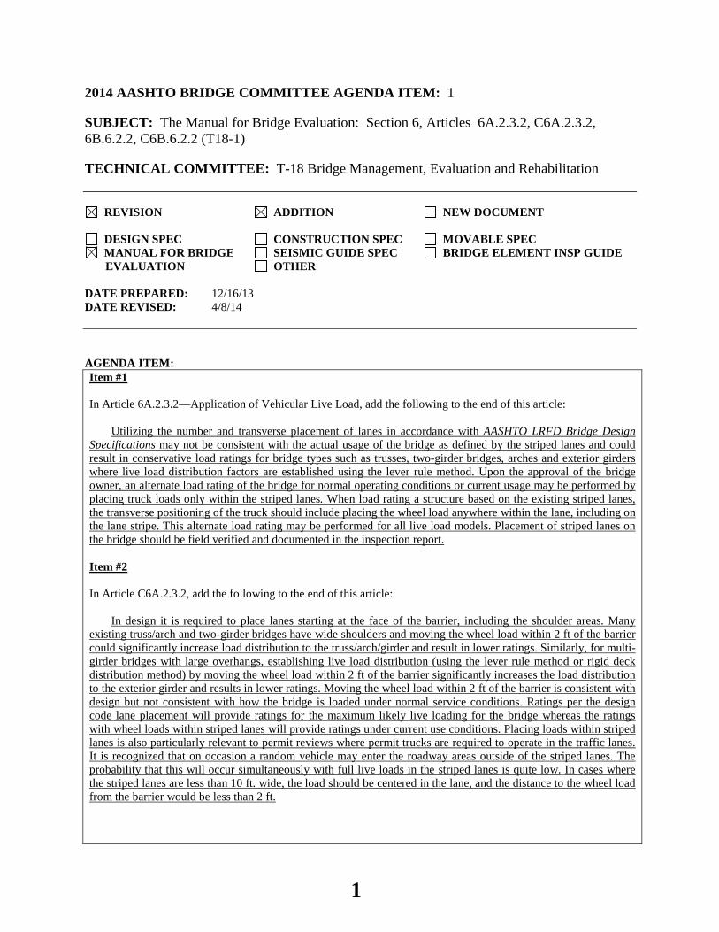
In Article 6A.2.3.2—Application of Vehicular Live Load, add the following to the end of this article:
Utilizing the number and transverse placement of lanes in accordance with AASHTO LRFD Bridge Design Specifications may not be consistent with the actual usage of the bridge as defined by the striped lanes and could result in conservative load ratings for bridge types such as trusses, two-girder bridges, arches and exterior girders where live load distribution factors are established using the lever rule method. Upon the approval of the bridge owner, an alternate load rating of the bridge for normal operating conditions or current usage may be performed by placing truck loads only within the striped lanes. When load rating a structure based on the existing striped lanes, the transverse positioning of the truck should include placing the wheel load anywhere within the lane, including on the lane stripe. This alternate load rating may be performed for all live load models. Placement of striped lanes on the bridge should be field verified and documented in the inspection report.
Item #2
In Article C6A.2.3.2, add the following to the end of this article:
In design it is required to place lanes starting at the face of the barrier, including the shoulder areas. Many existing truss/arch and two-girder bridges have wide shoulders and moving the wheel load within 2 ft of the barrier could significantly increase load distribution to the truss/arch/girder and result in lower ratings. Similarly, for multi-girder bridges with large overhangs, establishing live load distribution (using the lever rule method or rigid deck distribution method) by moving the wheel load within 2 ft of the barrier significantly increases the load distribution to the exterior girder and results in lower ratings. Moving the wheel load within 2 ft of the barrier is consistent with design but not consistent with how the bridge is loaded under normal service conditions. Ratings per the design code lane placement will provide ratings for the maximum likely live loading for the bridge whereas the ratings with wheel loads within striped lanes will provide ratings under current use conditions. Placing loads within striped lanes is also particularly relevant to permit reviews where permit trucks are required to operate in the traffic lanes. It is recognized that on occasion a random vehicle may enter the roadway areas outside of the striped lanes. The probability that this will occur simultaneously with full live loads in the striped lanes is quite low. In cases where the striped lanes are less than 10 ft. wide, the load should be centered in the lane, and the distance to the wheel load from the barrier would be less than 2 ft.
1
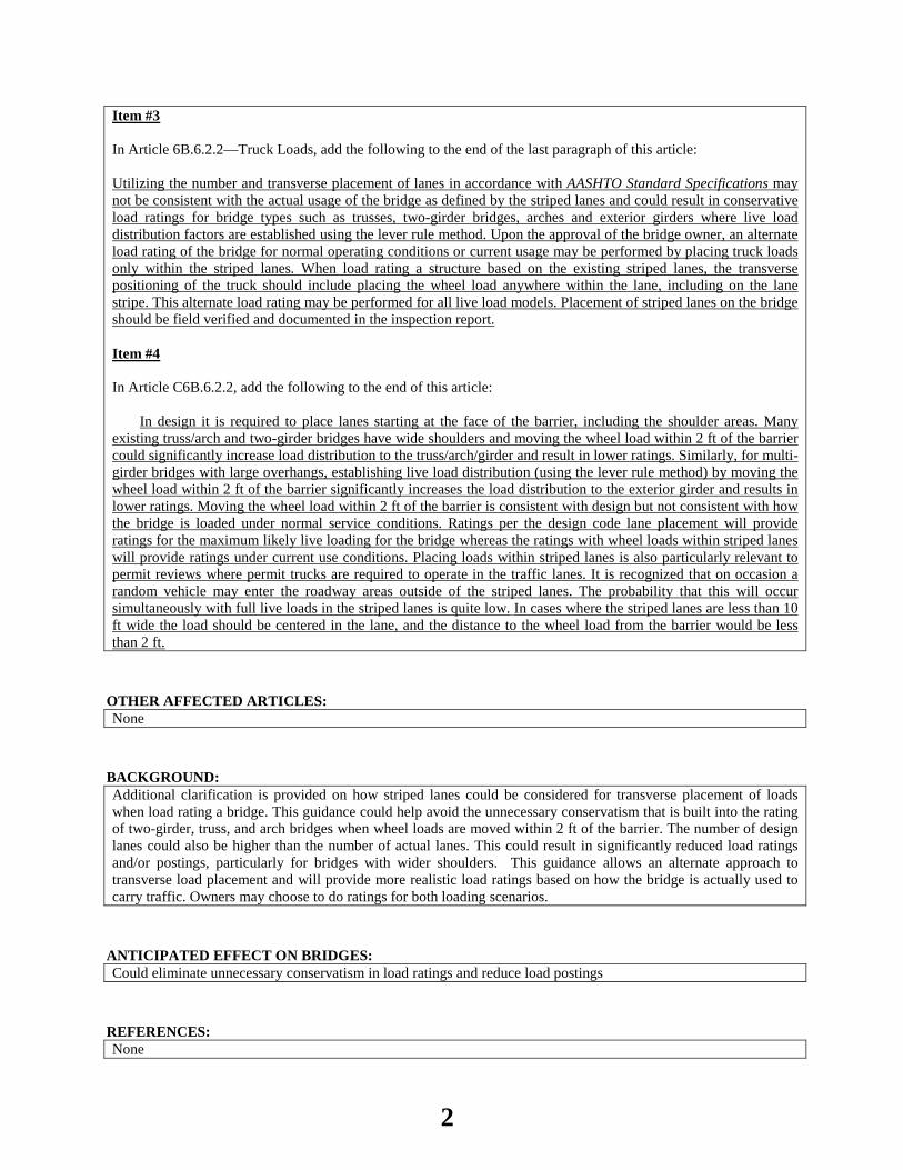
Item #3
In Article 6B.6.2.2—Truck Loads, add the following to the end of the last paragraph of this article:
Utilizing the number and transverse placement of lanes in accordance with AASHTO Standard Specifications may not be consistent with the actual usage of the bridge as defined by the striped lanes and could result in conservative load ratings for bridge types such as trusses, two-girder bridges, arches and exterior girders where live load distribution factors are established using the lever rule method. Upon the approval of the bridge owner, an alternate load rating of the bridge for normal operating conditions or current usage may be performed by placing truck loads only within the striped lanes. When load rating a structure based on the existing striped lanes, the transverse positioning of the truck should include placing the wheel load anywhere within the lane, including on the lane stripe. This alternate load rating may be performed for all live load models. Placement of striped lanes on the bridge should be field verified and documented in the inspection report.
Item #4
In Article C6B.6.2.2, add the following to the end of this article:
In design it is required to place lanes starting at the face of the barrier, including the shoulder areas. Many existing truss/arch and two-girder bridges have wide shoulders and moving the wheel load within 2 ft of the barrier could significantly increase load distribution to the truss/arch/girder and result in lower ratings. Similarly, for multi-girder bridges with large overhangs, establishing live load distribution (using the lever rule method) by moving the wheel load within 2 ft of the barrier significantly increases the load distribution to the exterior girder and results in lower ratings. Moving the wheel load within 2 ft of the barrier is consistent with design but not consistent with how the bridge is loaded under normal service conditions. Ratings per the design code lane placement will provide ratings for the maximum likely live loading for the bridge whereas the ratings with wheel loads within striped lanes will provide ratings under current use conditions. Placing loads within striped lanes is also particularly relevant to permit reviews where permit trucks are required to operate in the traffic lanes. It is recognized that on occasion a random vehicle may enter the roadway areas outside of the striped lanes. The probability that this will occur simultaneously with full live loads in the striped lanes is quite low. In cases where the striped lanes are less than 10 ft wide the load should be centered in the lane, and the distance to the wheel load from the barrier would be less than 2 ft.
OTHER AFFECTED ARTICLES:None
BACKGROUND:Additional clarification is provided on how striped lanes could be considered for transverse placement of loads when load rating a bridge. This guidance could help avoid the unnecessary conservatism that is built into the rating of two-girder, truss, and arch bridges when wheel loads are moved within 2 ft of the barrier. The number of design lanes could also be higher than the number of actual lanes. This could result in significantly reduced load ratings and/or postings, particularly for bridges with wider shoulders. This guidance allows an alternate approach to transverse load placement and will provide more realistic load ratings based on how the bridge is actually used to carry traffic. Owners may choose to do ratings for both loading scenarios.
ANTICIPATED EFFECT ON BRIDGES:Could eliminate unnecessary conservatism in load ratings and reduce load postings
REFERENCES: None
2

OTHER: None
3
2014 AASHTO BRIDGE COMMITTEE AGENDA ITEM: 2 SUBJECT: The Manual for Bridge Evaluation: Section 6, Article C6A.6.8, Appendices I6A and A (T18-3) TECHNICAL COMMITTEE: T-18 Bridge Management, Evaluation and Rehabilitation
REVISION ADDITION NEW DOCUMENT
DESIGN SPEC CONSTRUCTION SPEC MOVABLE SPEC MANUAL FOR BRIDGE SEISMIC GUIDE SPEC BRIDGE ELEMENT INSP GUIDE
EVALUATION OTHER DATE PREPARED: 1/6/14 DATE REVISED: 4/9/14 AGENDA ITEM:Item #1 Revise Article C6A.6.8 as follows:
Load rating of such members should consider second-order effects, which may be approximated by the single-
step moment magnification method given in LRFD Design Article 4.5.3.2.2b (see Appendix H6A). In compression members with asymmetrical sections (such as truss chords), the gravity axis of the section may
not coincide with the working lines, resulting in an eccentric connection. Compression members having equal end eccentricities are conveniently analyzed using the secant formula. The LRFD specification does not utilize the secant formula, but provides an interaction equation for the design of members with combined axial loads and concurrent moments. Rating compression members via an interaction equation can be somewhat tedious as an iterative approach may be required to establish the governing rating. A rating approach using the interaction equation is given in Appendix H6A. (Mr must be known to apply this method.)
As an alternative to analyzing axial compression members with eccentric connections as combined compression-flexure members, an axial load magnification factor may be applied to rate the member as a concentrically loaded member with an equivalent load. Secant formula is used to include the first and second order bending effects to produce a magnified axial load (dead and live) that would produce a constant stress over the cross-section equal to the peak stress in an eccentric member. This approach is applicable to members assumed to be pinned at the ends and without lateral loads on the member. Pin connected compression chord members in truss bridges are a common example of this type. An advantage inherent in this method is that rating factors can be computed without having to first determine Mr, which can be difficult to do for nonstandard truss sections (see Appendix I6A).
In compression members with asymmetrical sections (such as truss chords), the gravity axis of the section may not coincide with the working lines, resulting in an eccentric connection. Compression members having equal end eccentricities may be analyzed using the secant formula (Appendix I6A) or the LRFD interaction equation for the design of members with combined axial loads and concurrent moments (Appendix H6A).
Rating compression members via an interaction equation may require an iterative approach to establish the governing rating. A rating approach using the interaction equation is given in Appendix H6A (Mr must be known to apply this method). Furthermore, the interaction equations specified in the LRFD Article 6.9.2.2 “Combined Axial Compression and Flexure” do not address these asymmetrical members. However, axially loaded members with eccentric connection members could be treated as concentrically loaded members with applied moments of Pe at the connection (where e is the eccentricity at the support). A rating example of a compression member with eccentric connection using the approach listed in Appendix H6A is given in Appendix A6.
As an alternative to analyzing axial compression members with eccentric connections as combined compression-flexure members, an axial load magnification factor may be applied to rate the member as a
4
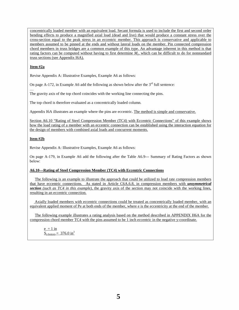
concentrically loaded member with an equivalent load. Secant formula is used to include the first and second order bending effects to produce a magnified axial load (dead and live) that would produce a constant stress over the cross-section equal to the peak stress in an eccentric member. This approach is conservative and applicable to members assumed to be pinned at the ends and without lateral loads on the member. Pin connected compression chord members in truss bridges are a common example of this type. An advantage inherent in this method is that rating factors can be computed without having to first determine Mr, which can be difficult to do for nonstandard truss sections (see Appendix I6A). Item #2a Revise Appendix A: Illustrative Examples, Example A6 as follows: On page A-172, in Example A6 add the following as shown below after the 3rd full sentence: … The gravity axis of the top chord coincides with the working line connecting the pins. The top chord is therefore evaluated as a concentrically loaded column. Appendix I6A illustrates an example where the pins are eccentric. The method is simple and conservative. Section A6.10 “Rating of Steel Compression Member (TC4) with Eccentric Connections” of this example shows how the load rating of a member with an eccentric connection can be established using the interaction equation for the design of members with combined axial loads and concurrent moments. Item #2b Revise Appendix A: Illustrative Examples, Example A6 as follows: On page A-179, in Example A6 add the following after the Table A6.9--- Summary of Rating Factors as shown below: A6.10---Rating of Steel Compression Member (TC4) with Eccentric Connections
The following is an example to illustrate the approach that could be utilized to load rate compression members that have eccentric connections. As stated in Article C6A.6.8, in compression members with unsymmetrical section (such as TC4 in this example), the gravity axis of the section may not coincide with the working lines, resulting in an eccentric connection.
Axially loaded members with eccentric connections could be treated as concentrically loaded member, with an equivalent applied moment of Pe at both ends of the member, where e is the eccentricity at the end of the member.
The following example illustrates a rating analysis based on the method described in APPENDIX H6A for the compression chord member TC4 with the pins assumed to be 1 inch eccentric in the negative y-coordinate.
e = 1 in Sz-bottom = 376.0 in3
5
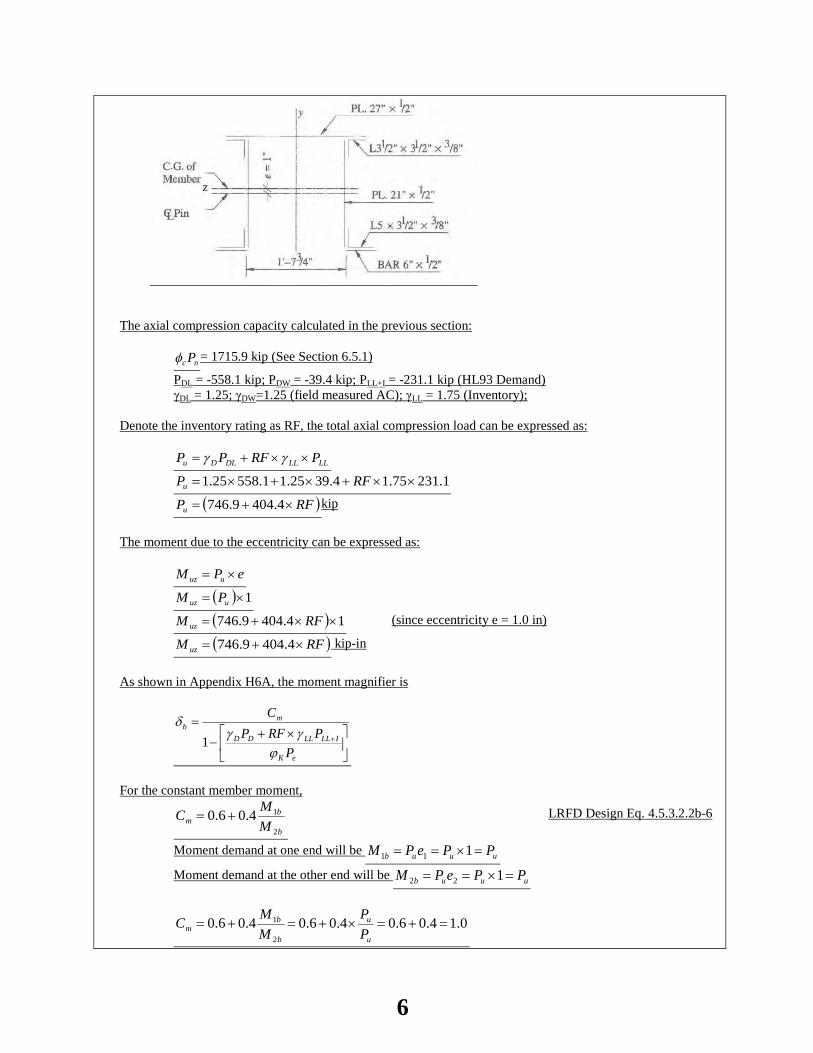
The axial compression capacity calculated in the previous section:
nc Pφ = 1715.9 kip (See Section 6.5.1)
PDL = -558.1 kip; PDW = -39.4 kip; PLL+I = -231.1 kip (HL93 Demand) γDL = 1.25; γDW=1.25 (field measured AC); γLL = 1.75 (Inventory);
Denote the inventory rating as RF, the total axial compression load can be expressed as:
LLLLDLDu PRFPP ××+= γγ
1.23175.14.3925.11.55825.1 ××+×+×= RFPu
( )RFPu ×+= 4.4049.746 kip
The moment due to the eccentricity can be expressed as:
ePM uuz ×=
( ) 1×= uuz PM
( ) 14.4049.746 ××+= RFM uz (since eccentricity e = 1.0 in)
( )RFM uz ×+= 4.4049.746 kip-in
As shown in Appendix H6A, the moment magnifier is
×+−
=+
eK
ILLLLDD
mb
PPRFP
C
ϕγγ
δ1
For the constant member moment,
b
bm M
MC2
14.06.0 += LRFD Design Eq. 4.5.3.2.2b-6
Moment demand at one end will be uuub PPePM =×== 111
Moment demand at the other end will be uuub PPePM =×== 122
0.14.06.04.06.04.06.02
1 =+=×+=+=u
u
b
bm P
PMMC
6
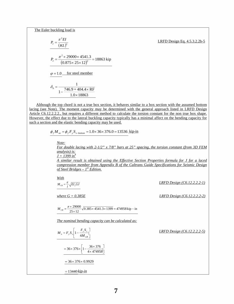
The Euler buckling load is
( )22
KLEI
Pe
π= LRFD Design Eq. 4.5.3.2.2b-5
( )kip18863
1225875.03.454129000
2
2
=××××
=π
eP
0.1=ϕ for steel member
188631.0RF404.4 + 746.91
1
××
−=bδ
Although the top chord is not a true box section, it behaves similar to a box section with the assumed bottom
lacing (see Note). The moment capacity may be determined with the general approach listed in LRFD Design Article C6.12.2.2.2., but requires a different method to calculate the torsion constant for the non true box shape. However, the effect due to the lateral buckling capacity typically has a minimal affect on the bending capacity for such a section and the elastic bending capacity may be used.
135360.376360.1 =××== −bottomzyfnzf SFM φφ kip-in
Note: For double lacing with 2-1/2” x 7/8” bars at 25” spacing, the torsion constant (from 3D FEM analysis) is: J = 1399 in4
A similar result is obtained using the Effective Section Properties formula for J for a laced compression member from Appendix B of the Caltrans Guide Specifications for Seismic Design of Steel Bridges – 1st Edition.
With GJEI
lM yCR
π= LRFD Design (C6.12.2.2.2-1)
where G = 0.385E LRFD Design (C6.12.2.2.2-2)
inkip47495813993.4541385.01225
29000−=××
××
=π
CRM
The nominal bending capacity can be calculated as:
−=
CR
zyzyn M
SFSFM
41 LRFD Design (C6.12.2.2.2-5)
××
−××=4749584
37636137636
9929.037636 ××= 13440= kip-in
7
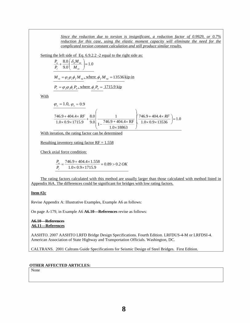
Since the reduction due to torsion is insignificant, a reduction factor of 0.9929, or 0.7% reduction for this case, using the elastic moment capacity will eliminate the need for the complicated torsion constant calculation and still produce similar results.
Setting the left side of Eq. 6.9.2.2 -2 equal to the right side as:
0.10.90.8
=
+
rz
uzb
r
u
MM
PP δ
nzfcsrz MM φϕϕ= , where 13536=nzf Mφ kip-in
nccsr PP φϕϕ= , where =nc Pφ 1715.9 kip
With
,0.1=cϕ 9.0=sϕ
0.1135369.00.14.4049.746
188631.0RF404.4 + 746.91
10.90.8
9.17159.00.14.4049.746
=
×××+
××
−+
×××+ RFRF
With iteration, the rating factor can be determined
Resulting inventory rating factor RF = 1.558
Check axial force condition:
OKPP
r
u 2.089.09.17159.00.1558.14.4049.746
>=××
×+=
The rating factors calculated with this method are usually larger than those calculated with method listed in Appendix I6A. The differences could be significant for bridges with low rating factors.
Item #2c Revise Appendix A: Illustrative Examples, Example A6 as follows: On page A-179, in Example A6 A6.10---References revise as follows: A6.10—References A6.11---References
AASHTO. 2007 AASHTO LRFD Bridge Design Specifications. Fourth Edition. LRFDUS-4-M or LRFDSI-4. American Association of State Highway and Transportation Officials. Washington, DC. CALTRANS. 2001 Caltrans Guide Specifications for Seismic Design of Steel Bridges. First Edition.
OTHER AFFECTED ARTICLES:None
8
BACKGROUND:The secant formula (I6A-1) in Appendix I6A is listed as “an alternative to analyzing axial compression
members with eccentric connections as combined compression-flexure members (LRFD Design Article 6.9.2.2).” This approach is similar in principle to the secant formula used in the Working Stress method of AASHTO Bridge Specifications before 1977. This is a very conservative method, which uses the column axial compression buckling stress capacity to check the combined compression stress from axial compression and bending moment.
With given section properties and loads listed in Appendix I6A on page 6-76, the inventory rating factor is 1.45 with the secant formula. However the inventory rating using LRFD Design Article 6.9.2.2 will be 1.55. Although the rating factor with LRFD Design Specification is only 7% larger than that using the secant formula for this MBE example, the difference will be much greater on bridges with lower capacities. For example, Bridge 30C0016 is a Through Pratt Truss county bridge in California built in 1912. The rating factor for the Type 3 truck would be -0.033 using the secant formula from Appendix I6A, but will be 0.5 using LRFD Design Article 6.9.2.2. The difference between the rating results from the two different analysis methods goes from closing the bridge to an open bridge with a 13 ton posting.
ANTICIPATED EFFECT ON BRIDGES:Increased rating values for truss bridges having compression members with eccentric connections.
REFERENCES:
1) AASHTO MBE 2011, Article 6A.6.8 2) AASHTO MBE 2011, Section 6, Appendix I6A, Appendix H6A 3) AASHTO MBE 2011, Appendix A, A6
OTHER: None
9
2014 AASHTO BRIDGE COMMITTEE AGENDA ITEM: 3 SUBJECT: The Manual for Bridge Evaluation: Section 6, Article C6A.4.4.2.1b (T18-4) TECHNICAL COMMITTEE: T-18 Bridge Management, Evaluation and Rehabilitation
REVISION ADDITION NEW DOCUMENT
DESIGN SPEC CONSTRUCTION SPEC MOVABLE SPEC MANUAL FOR BRIDGE SEISMIC GUIDE SPEC BRIDGE ELEMENT INSP GUIDE
EVALUATION OTHER DATE PREPARED: 12/16/13 DATE REVISED: 5/13/14 AGENDA ITEM:
Revise Article C6A.4.4.2.1b as follows: The vehicles referred to as specialized hauling vehicles (SHV) are legal single-unit short-wheelbase multiple-axle
trucks commonly used in the construction, waste management, bulk cargo and commodities hauling industries. Trucks weighing up to 80 kips are typically allowed unrestricted operation and are generally considered
“legal” provided they meet weight guidelines of Federal Bridge Formula B (Formula B). In the past, the maximum legal weight for short-wheelbase trucks was usually controlled by Formula B rather than by the 80 kips gross weight limit. Since the adoption of the AASHTO family of three legal loads, the trucking industry has introduced specialized single-unit trucks with closely spaced multiple axles that make it possible for these short-wheelbase trucks to carry the maximum load of up to 80,000 lb and still meet Formula B. The AASHTO family of three legal loads selected at the time to closely match the Formula B in the short, medium, and long truck length ranges do not represent these newer axle configurations. These SHV trucks cause force effects that exceed the stresses induced by HS-20 in bridges by up to 22 percent and by the Type 3, 3S2, or 3-3 posting vehicles by over 50 percent, in certain cases. The shorter bridge spans are most sensitive to the newer SHV axle configurations.
The notional rating load (NRL) represents a single load model that will envelop the load effects on simple and continuous span bridges of the worst possible Formula B single-unit truck configurations with multiple axles up to 80 kips. It is called “notional” because it is not intended to represent any particular truck. Vehicles considered to be representative of the newer Formula B configurations were investigated through the analysis of weigh-in-motion data and other truck and survey data obtained from the States (refer to NCHRP Report 575). Bridges that rate for the NRL loading will have adequate load capacity for all legal Formula B truck configurations up to 80 kips. Bridges that do not rate for the NRL loading should be investigated to determine posting needs using the single-unit posting loads SU4, SU5, SU6, and SU7, specified in Article 6A.8.2. These SU trucks were developed to model the extreme loading effects of single-unit SHVs with four or more axles.
The Federal tandem axle weight limit on the Interstate System is 34,000 pounds. Although tandem axles are generally defined as an axle group consisting of two axles, CFR Title 23 658.5 defines tandem axle in terms of the distance between the outer axles. That is two or more consecutive axles whose centers may be spaced more than 40 inches and not more than 96 inches apart,
By this definition, the total weight on three axles spaced at 8 feet between the outer axles would be limited to 34,000 pounds. Spacings, even slightly above 8 feet would be governed by Formula B with a maximum weight of 42,000 pounds.
The SHVs referenced in 6A.8.2 are load models for rating and posting that show three axle groups with a spacing of 8 feet between the outer axles and a total weight on the three axles of 42,000 lbs. This is not in strict compliance with the tandem axle definition in the CFR. However, these load models provide analysis efficiency in load ratings by serving as envelope vehicles and are not meant as examples of real trucks, where the actual axle
10

spacings may be slightly different. In context of the previous paragraph, for all practical purposes, All the SHVs are compliant with Formula B. In the NRL loading, axles that do not contribute to the maximum load effect under consideration should be
neglected. For instance, axles that do not contribute to the maximum positive moments need to be neglected or they will contribute to bending in the opposite (negative) direction. This requirement may only affect certain continuous bridges, usually with short span lengths. The drive axle spacing of 6 ft may also be increased up to 14 ft to maximize load effects. Increasing the drive axle spacing to 14 ft could result in a slight increase in moments, again in continuous span bridges. It is unnecessary to consider more than one NRL loading per lane. Load ratings may also be performed for State legal loads that have only minor variations from the AASHTO legal loads using the live load factors provided in Tables 6A.4.4.2.3a-1 and 6A.4.4.2.3b-1.
OTHER AFFECTED ARTICLES:None
BACKGROUND:Although tandem axles are generally defined as an axle group consisting of 2 axles, CFR Title 23 658.5 has a definition where the tandem axle is defined in terms of the distance between the outer axles, regardless of the number of axles in between. The CFR definition is as follows:
The SHVs referenced in Article 6A.8.2 are load models for rating and posting that show three axle groups with a spacing of 8 feet between the outer axles and a total weight on the three axles of 42,000 lbs. This is not in strict compliance with the tandem axle definition in the CFR. The new paragraph adds clarifying language pertaining to the definition of tandem axles in the CFR and possible implications for the SHV loadings in the MBE. It notes that the SHV load models provide analysis efficiency in load ratings by serving as envelope vehicles and are not meant as examples of real trucks. No modifications to the SHV load models is required.
ANTICIPATED EFFECT ON BRIDGES:Clarifies the use of the SHV trucks for load ratings and compliance with CFR definitions.
REFERENCES:
1. CFR Title 23 658.5 2. Sivakumar, B., et. al (2007) NCHRP Report 575, Legal Truck Loads and AASHTO Legal Loads for
Posting; Transportation Research Board, National Research Council, Washington. D.C.
OTHER: None
11

2014 AASHTO BRIDGE COMMITTEE AGENDA ITEM: 4 SUBJECT: The Manual for Bridge Evaluation: Section 6, Articles 6A.5.8 and 6B.5.2.4.3 (T18-5) TECHNICAL COMMITTEE: T-18 Bridge Management, Evaluation and Rehabilitation
REVISION ADDITION NEW DOCUMENT
DESIGN SPEC CONSTRUCTION SPEC MOVABLE SPEC MANUAL FOR BRIDGE SEISMIC GUIDE SPEC BRIDGE ELEMENT INSP GUIDE
EVALUATION OTHER DATE PREPARED: 1/6/14 DATE REVISED: 4/14/14 AGENDA ITEM:
Item #1
Add the following to the end of Article 6A.5.8: Whenever the shear failure plane crosses multiple stirrup zones, as shown in Figure 6A.5.8-1, the capacity due
to shear reinforcement may be established using the average shear reinforcement area per unit length (Av/S) existing within the shear failure plane. The average Av/S can be established using Eq. 6A.5.8-1.
( )θCotd
aSA
SA
v
ii
v
avg
v∑
=
(6A.5.8-1)
where:
Av = area of shear reinforcement
S = spacing of shear stirrups
ai = horizontal distance of shear plane crossing the stirrup zone i
dv = effective shear depth
θ = angle inclination of shear failure plane
12
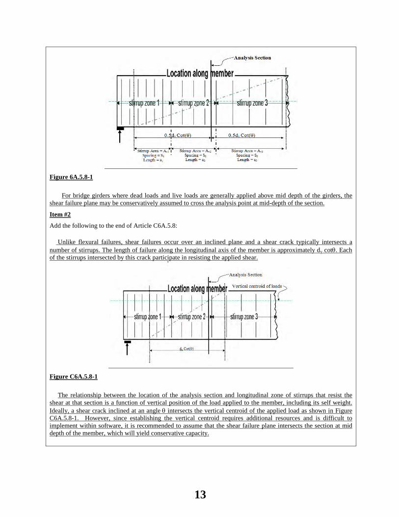
Figure 6A.5.8-1
For bridge girders where dead loads and live loads are generally applied above mid depth of the girders, the
shear failure plane may be conservatively assumed to cross the analysis point at mid-depth of the section.
Item #2
Add the following to the end of Article C6A.5.8: Unlike flexural failures, shear failures occur over an inclined plane and a shear crack typically intersects a number of stirrups. The length of failure along the longitudinal axis of the member is approximately dv cotθ. Each of the stirrups intersected by this crack participate in resisting the applied shear.
Figure C6A.5.8-1
The relationship between the location of the analysis section and longitudinal zone of stirrups that resist the shear at that section is a function of vertical position of the load applied to the member, including its self weight. Ideally, a shear crack inclined at an angle θ intersects the vertical centroid of the applied load as shown in Figure C6A.5.8-1. However, since establishing the vertical centroid requires additional resources and is difficult to implement within software, it is recommended to assume that the shear failure plane intersects the section at mid depth of the member, which will yield conservative capacity.
13

OTHER AFFECTED ARTICLES:None
BACKGROUND:LRFD C5.8.3.2 provides guidance for a more liberal yet conservative approach of incorporating potentially more shear stirrups at a given design/analysis section. This may be particularly helpful for load rating girders designed using LRFD or the Standard Specification and then load rated using LRFR. This ballot item incorporates the guidance of the LRFD 5.8.3.2 commentary into the MBE Section 6A. Most load rating software determines shear stirrup area at a given location from a stirrup spacing input by the user. For the present, if the shear capacities determined by the software are producing low rating factors the user may want to input into the rating software a modified spacing as determined from this revised article.
ANTICIPATED EFFECT ON BRIDGES:More accurate shear capacity determination.
REFERENCES: MBE Articles 6A.5.8 and 6B.5.2.4.3
OTHER: None
14
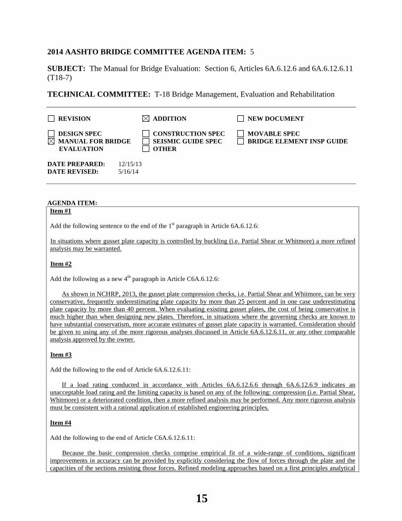
2014 AASHTO BRIDGE COMMITTEE AGENDA ITEM: 5 SUBJECT: The Manual for Bridge Evaluation: Section 6, Articles 6A.6.12.6 and 6A.6.12.6.11 (T18-7) TECHNICAL COMMITTEE: T-18 Bridge Management, Evaluation and Rehabilitation
REVISION ADDITION NEW DOCUMENT
DESIGN SPEC CONSTRUCTION SPEC MOVABLE SPEC MANUAL FOR BRIDGE SEISMIC GUIDE SPEC BRIDGE ELEMENT INSP GUIDE
EVALUATION OTHER DATE PREPARED: 12/15/13 DATE REVISED: 5/16/14 AGENDA ITEM:Item #1 Add the following sentence to the end of the 1st paragraph in Article 6A.6.12.6: In situations where gusset plate capacity is controlled by buckling (i.e. Partial Shear or Whitmore) a more refined analysis may be warranted. Item #2 Add the following as a new 4th paragraph in Article C6A.6.12.6:
As shown in NCHRP, 2013, the gusset plate compression checks, i.e. Partial Shear and Whitmore, can be very conservative, frequently underestimating plate capacity by more than 25 percent and in one case underestimating plate capacity by more than 40 percent. When evaluating existing gusset plates, the cost of being conservative is much higher than when designing new plates. Therefore, in situations where the governing checks are known to have substantial conservatism, more accurate estimates of gusset plate capacity is warranted. Consideration should be given to using any of the more rigorous analyses discussed in Article 6A.6.12.6.11, or any other comparable analysis approved by the owner.
Item #3 Add the following to the end of Article 6A.6.12.6.11:
If a load rating conducted in accordance with Articles 6A.6.12.6.6 through 6A.6.12.6.9 indicates an
unacceptable load rating and the limiting capacity is based on any of the following: compression (i.e. Partial Shear, Whitmore) or a deteriorated condition, then a more refined analysis may be performed. Any more rigorous analysis must be consistent with a rational application of established engineering principles. Item #4 Add the following to the end of Article C6A.6.12.6.11:
Because the basic compression checks comprise empirical fit of a wide-range of conditions, significant
improvements in accuracy can be provided by explicitly considering the flow of forces through the plate and the capacities of the sections resisting those forces. Refined modeling approaches based on a first principles analytical
15
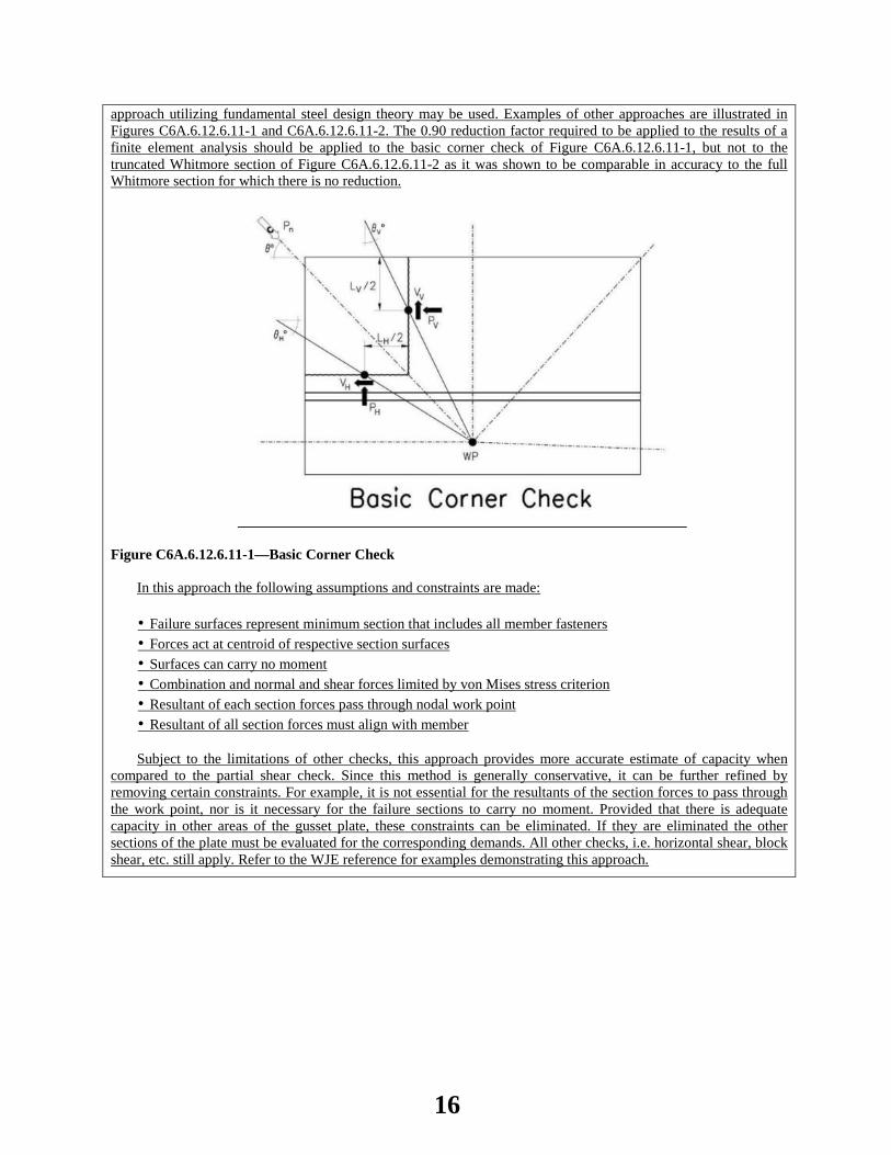
approach utilizing fundamental steel design theory may be used. Examples of other approaches are illustrated in Figures C6A.6.12.6.11-1 and C6A.6.12.6.11-2. The 0.90 reduction factor required to be applied to the results of a finite element analysis should be applied to the basic corner check of Figure C6A.6.12.6.11-1, but not to the truncated Whitmore section of Figure C6A.6.12.6.11-2 as it was shown to be comparable in accuracy to the full Whitmore section for which there is no reduction.
Figure C6A.6.12.6.11-1—Basic Corner Check In this approach the following assumptions and constraints are made: • Failure surfaces represent minimum section that includes all member fasteners • Forces act at centroid of respective section surfaces • Surfaces can carry no moment • Combination and normal and shear forces limited by von Mises stress criterion • Resultant of each section forces pass through nodal work point • Resultant of all section forces must align with member Subject to the limitations of other checks, this approach provides more accurate estimate of capacity when
compared to the partial shear check. Since this method is generally conservative, it can be further refined by removing certain constraints. For example, it is not essential for the resultants of the section forces to pass through the work point, nor is it necessary for the failure sections to carry no moment. Provided that there is adequate capacity in other areas of the gusset plate, these constraints can be eliminated. If they are eliminated the other sections of the plate must be evaluated for the corresponding demands. All other checks, i.e. horizontal shear, block shear, etc. still apply. Refer to the WJE reference for examples demonstrating this approach.
16

• The Truncated Whitmore Section Method was developed at the Georgia Institute of Technology by
Dr. Donald White, et al., as a part of the NCHRP 12-84 Project. Illustrative examples of its application are found in Appendix I, Section 5 of the Final Report, and designated Method 2.
• In utilizing the Truncated Whitmore Section Method, the equations found in Article 6A.6.12.6.7 are applicable, except that the constant value 3.29 in Eq. 6A.6.12.6.7-4 is to be replaced with the value 6.71, due to calibration differences between Method 1 (Partial Shear Plane Method) and Method 2.
• When computing the nominal compression resistance Pn, the tributary portions of the gusset gross cross sectional area above the base dimensional widths WL and WR are to be reduced 10 percent.
OTHER AFFECTED ARTICLES:None
BACKGROUND:Illustrative examples comparing the capacity calculations of a gusset plate joint utilizing the Full Whitmore Section, Partial Shear Plane and Truncated Whitmore Section Methods are shown for information in Attachment 1.
ANTICIPATED EFFECT ON BRIDGES:Practitioners who have utilized the provisions of the 2013 AASHTO MBE Articles 6A.6.12.6 through 6A.6.12.6.11, as well as Appendix L6B.2.6 have noted conservatism in its approach to the capacities of gusset plates in certain instances. The “Basic Corner Check” based on a first-principles analytical approach utilizing fundamental steel design theory to conservatively calculate gusset plate limit state capacities at critical cross sections including those affected by deterioration offers a conservative alternative approach. Similarly, the Truncated Whitmore Method was calibrated as part of the NCHRP 12-84 project. Illustrations of its use are contained in Appendix I, Section 5 of the report.
REFERENCES: “Evaluations of Existing Gusset Plates”, Jonathon C McGormley, SE, Wiss, Janney, Elstner Associates, Inc.
17

OTHER: None
18

ATTACHMENT 1: Page 1 of 8
Truss Member U8-L9 Factored Loading (HL-93 with Future Wearing Surface)
DL 746 k
InvLL 397 k
OprLL 306 k
Method 1 Compression Buckling involves analyzing the gusset plates using the full Whitmoresection and the partial shear planes.
Method 1 Full Whitmore Section (fw) Gusset Plate Properties
Wfull 40.6 in E 29000 ksi tg 0.5 in (gusset plate thickness)
Lmid 10.3 in Fy 45 ksi
Dimensions Wfull and Lmid were scaled from a CAD drawing created using the gusset plateimaging procedure.
Method 1 Compression Buckling Gusset Plate Analysis Example
Determine Compressive Resistance using Full Whitmore Section (fw)
Ag Wfull tg Ag 20.30 in2
Pe 3.29E Ag
Lmidtg
2 Pe 4564.10 k
Po Fy Ag Po 913.50 k
19
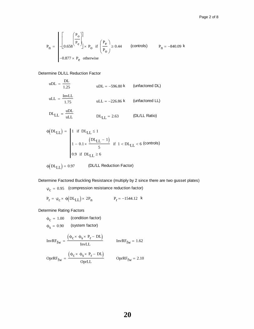
Page 2 of 8
Pn 0.658
Po
Pe
Po
PePo
0.44if
0.877 Pe otherwise
(controls) Pn 840.09 k
Determine DL/LL Reduction Factor
uDLDL1.25
uDL 596.80 k (unfactored DL)
uLLInvLL1.75
uLL 226.86 k (unfactored LL)
DLLLuDLuLL
DLLL 2.63 (DL/LL Ratio)
ϕ DLLL 1 DLLL 1if
1 0.1DLLL 1
5 1 DLLL 6if
0.9 DLLL 6if
(controls)
ϕ DLLL 0.97 (DL/LL Reduction Factor)
Determine Factored Buckling Resistance (multiply by 2 since there are two gusset plates)
φc 0.95 (compression resistance reduction factor)
Pr φc ϕ DLLL 2 Pn Pr 1544.12 k
Determine Rating Factors
ϕc 1.00 (condition factor)
ϕs 0.90 (system factor)
InvRFfwϕc ϕs Pr DL
InvLL InvRFfw 1.62
OprRFfwϕc ϕs Pr DL
OprLL OprRFfw 2.10
20
Page 3 of 8
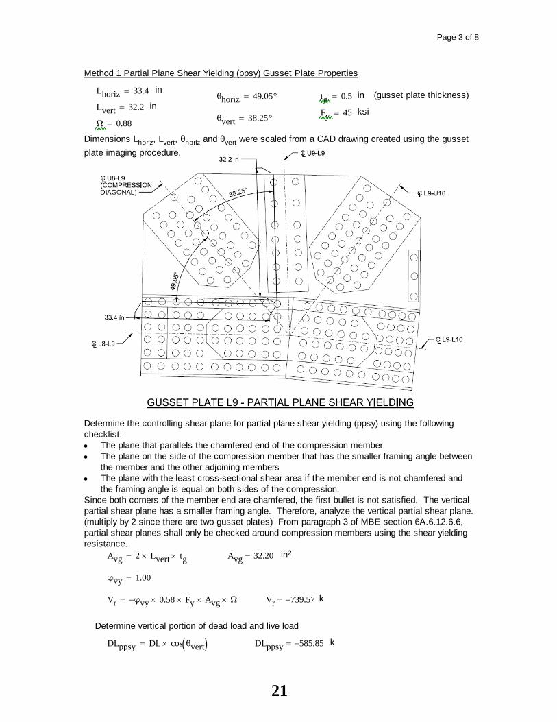
Method 1 Partial Plane Shear Yielding (ppsy) Gusset Plate Properties
Lhoriz 33.4 inθhoriz 49.05° tg 0.5 in (gusset plate thickness)
Lvert 32.2 inFy 45 ksi
θvert 38.25°Ω 0.88
Dimensions Lhoriz, Lvert, θhoriz and θvert were scaled from a CAD drawing created using the gussetplate imaging procedure.
Determine the controlling shear plane for partial plane shear yielding (ppsy) using the followingchecklist:
The plane that parallels the chamfered end of the compression memberThe plane on the side of the compression member that has the smaller framing angle betweenthe member and the other adjoining membersThe plane with the least cross-sectional shear area if the member end is not chamfered andthe framing angle is equal on both sides of the compression.
Since both corners of the member end are chamfered, the first bullet is not satisfied. The verticalpartial shear plane has a smaller framing angle. Therefore, analyze the vertical partial shear plane.(multiply by 2 since there are two gusset plates) From paragraph 3 of MBE section 6A.6.12.6.6,partial shear planes shall only be checked around compression members using the shear yieldingresistance.
Avg 2 Lvert tg Avg 32.20 in2
φvy 1.00
Vr φvy 0.58 Fy Avg Ω Vr 739.57 k
Determine vertical portion of dead load and live load
DLppsy DL cos θvert DLppsy 585.85 k
21

Page 4 of 8
InvLLppsy InvLL cos θvert InvLLppsy 311.77 k
OprLLppsy OprLL cos θvert OprLLppsy 240.31 k
Determine DL/LL Reduction Factor
uDLppsyDLppsy
1.25 uDLppsy 468.68 k (unfactored DL)
uLLppsyInvLLppsy
1.75 uLLppsy 178.15 k (unfactored LL)
DLLLppsyuDLppsyuLLppsy
DLLLppsy 2.63 (DL/LL Ratio)
ϕ DLLLppsy 1 DLLLppsy 1if
1 0.1DLLLppsy 1
5 1 DLLLppsy 6if
0.9 DLLLppsy 6if
(controls)
ϕ DLLLppsy 0.97 (DL/LL Reduction Factor)
Determine Factored Shear Resistance
V ϕ DLLLppsy Vr V 715.45 k
Determine Rating Factors
ϕc 1.00 (condition factor)
ϕs 0.90 (system factor)
InvRFppsyϕc ϕs V DLppsy
InvLLppsy InvRFppsy 0.19
OprRFppsyϕc ϕs V DLppsy
OprLLppsy OprRFppsy 0.24
Determine controlling method 1 rating factor (minimum of full Whitmore section and partial planeshear yielding rating factors)
InvRFM1 min InvRFfw InvRFppsy InvRFM1 0.19
OprRFM1 min OprRFfw OprRFppsy OprRFM1 0.24
22

Page 5 of 8
Method 2 Compression Buckling Gusset Plate Analysis Example Truss Member U8-L9 Factored Loading (HL-93 with Future Wearing Surface)
DL 746 k
InvLL 397 k
OprLL 306 k
Method 2 Compression Buckling involves analyzing the gusset plates using the truncatedWhitmore section. Analyzing for partial plane shear yielding is not performed.
Method 2 Truncated Whitmore Section Gusset Plate Properties
WL 5.7 in LL 12.2 in tg 0.5 in (gusset plate thickness)
WM 24.3 in LM 11.4 in Fy 45 ksi
WR 4.4 in LR 10 in E 29000 ksi
Dimensions WL, WM, WR, LL, LM & LR were scaled from a CAD drawing created using the gussetplate imaging procedure.
where:
LM = perpendicular distance from the middle of the truncated Whitmore section, WM, to the nearest member fastener line in the direction parallel to the compression member
LL = perpendicular distance from the middle of the length bL to the closest fastener line on the compression member
23

Page 6 of 8
LR = perpendicular distance from the middle of the length bR to the closest fastener line on the compression member
WM = width between the points where the Whitmore section intersects the adjacent member fastener lines, or between the point where the Whitmore section is truncated by an adjacent member fastener line on one side of the compression member and the end of the Whitmore section on the other side of the member where the Whitmore section is not truncated by a fastener line, as applicable
WL = projection onto the Whitmore plane of a fastener line that truncates the Whitmore section on the left-hand side of the compression member, as applicable
WR = projection onto the Whitmore plane of a fastener line that truncates the Whitmore section on the right-hand side of the compression member, as applicable
bL = length on the left-hand side of the compression member between the point where the 30o
dispersion line intersects the adjacent fastener line, or from the free edge of the plate if the 30o dispersion line crosses the free edge, to the point where the fastener line intersects the Whitmore plane on the left-hand side of the member
bR = length on the right-hand side of the compression member between the point where the 30o
dispersion line intersects the adjacent fastener line, or from the free edge of the plate if the 30o dispersion line crosses the free edge, to the point where the fastener line intersects the Whitmore plane on the right-hand side of the member
Compute Euler Buckling Stress for Left, Middle and Right Portions of Truncated Whitmore Section(Warren Type Truss)
FeL 6.71E
LLtg
2 FeL 326.84 ksi
FeM 6.71E
LMtg
2 FeM 374.33 ksi
FeR 6.71E
LRtg
2 FeR 486.48 ksi
24

Page 7 of 8
Compute Buckling Capacity for Left, Middle and Right Portions of Truncated Whitmore Section(10% Reduction for Truncated Portions)
Left Portion:AgL WL tg AgL 2.85 in2
PnL 0.9 0.658
Fy
FeL
Fy AgL
FyFeL
2.25
if
0.9 0.877 FeL AgL otherwise
(controls)PnL 108.96 k
Middle Portion:AgM WM tgAgM 12.15 AgM 12.15 in2
PnM 0.658
Fy
FeM
Fy AgM
FyFeM
2.25
if
0.877 FeM AgM otherwise
(controls)PnM 519.92 k
Right Portion:AgR WR tg AgR 2.20 in2
PnR 0.9 0.658
Fy
FeR
Fy AgR
FyFeR
2.25
if
0.9 0.877 FeR AgR otherwise
(controls)PnR 85.72 k
Combine Resistances of Three Portions of Truncated Whitmore Section(multiply by 2 since there are two gusset plates)
Pn 2 PnL PnM PnR Pn 1429.20 k
Determine DL/LL Reduction Factor
uDLDL1.25
uDL 596.80 k (unfactored DL)
uLLInvLL1.75
uLL 226.86 k (unfactored LL)
DLLLuDLuLL
DLLL 2.63 (DL/LL Ratio)
25

Page 8 of 8
ϕ DLLL 1 DLLL 1if
1 0.1DLLL 1
5 1 DLLL 6if
0.9 DLLL 6if
(controls)
ϕ DLLL 0.97 (DL/LL Reduction Factor)
Determine Factored Buckling Resistance
φc 0.95 (compression resistance reduction factor)
Pr φc ϕ DLLL Pn Pr 1313.45 k
Determine Rating Factors
ϕc 1.00 (condition factor)
ϕs 0.9 (system factor)
InvRFM2ϕc ϕs Pr DL
InvLL InvRFM2 1.10
OprRFM2ϕc ϕs Pr DL
OprLL OprRFM2 1.43
26

2014 AASHTO BRIDGE COMMITTEE AGENDA ITEM: 6 SUBJECT: The Manual for Bridge Evaluation: Section 7, Various Articles (T18-8) TECHNICAL COMMITTEE: T-18 Bridge Management, Evaluation and Rehabilitation
REVISION ADDITION NEW DOCUMENT
DESIGN SPEC CONSTRUCTION SPEC MOVABLE SPEC MANUAL FOR BRIDGE SEISMIC GUIDE SPEC COASTAL GUIDE SPEC
EVALUATION OTHER DATE PREPARED: 12/12/13 DATE REVISED: AGENDA ITEM: Replace Section 7—Fatigue Evaluation of Steel Bridges with Attachment B.
OTHER AFFECTED ARTICLES:None
BACKGROUND:MBE Section 7 provisions are intended primarily for the fatigue evaluation of steel superstructure members. Section 7—Fatigue Evaluation of Steel Bridges of the AASHTO Manual for Bridge Evaluation (MBE), incorporates the material derived from The AASHTO Guide Specifications for Fatigue Evaluation of Existing Steel Bridges, which is more than 20 years old. In recent years, more information on steel bridges has been developed that provides a foundation upon which to update the procedures for fatigue evaluation of steel bridges. Areas that have been improved include: (a) methods of estimating total and remaining fatigue life as the current methods can result in unrealistic and inaccurate predictions, (b) guidance on the evaluation of retrofit and repair details used to address fatigue cracks, and (c) guidance for the evaluation of distortion-induced fatigue cracks. A new methodology to evaluate fatigue serviceability using a non-dimensional parameter, named the fatigue serviceability index (FSI), has been developed. This avoids the undesirable connotation of remaining fatigue life. The research that proposed these updates to Section 7was performed under NCHRP Project 12-81, “Evaluation of Fatigue on the Serviceability of Highway Bridges”.
ANTICIPATED EFFECT ON BRIDGES:The revision of Section 7 of the MBE advances the state of the art and the practice with regard to fatigue evaluation of steel bridges. It provides improved methods utilizing a reliability-based approach to assess the fatigue behavior and aid bridge owners in making appropriate operational decisions. Guidance for the evaluation of distortion-induced fatigue cracks and guidance on the evaluation of retrofit and repair details are some additional key findings from this study.
27

REFERENCES: AASHTO. 1990. Guide Specifications for Fatigue Evaluation of Existing Steel Bridges. American Association of State Highway and Transportation Officials, Washington, DC. AASHTO. 2012. AASHTO LRFD Bridge Design Specifications, Sixth Edition, American Association of State Highway and Transportation Officials, Washington, DC. Bowman, M.D., G. Fu, Y.E. Zhou, R.J. Connor, A. A. Godbole. 2012. Fatigue Evaluation of Steel Bridges, NCHRP Report 721. Transportation Research Board, National Research Council, Washington. D.C.
OTHER: None
28
ATTACHMENT B (Replacement of Section 7) – 2014 AGENDA ITEM 6 - T -18 (T18-8) Recommended Revisions to the AASHTO MBE Section 7
7.1—LOAD-INDUCED VERSUS DISTORTION-INDUCED FATIGUE
C7.1
Fatigue damage has been traditionally categorized as
either due to load-induced or distortion-induced fatigue damage.
Load-induced fatigue is that due to the in-plane stresses in the steel plates that comprise bridge member cross-sections. These in-plane stresses are those typically calculated by designers during bridge design or evaluation.
The previous most comprehensive codification of fatigue evaluation of steel bridges, the Guide Specifications for Fatigue Evaluation of Existing Steel Bridges (AASHTO, 1990), explicitly considered only load-induced fatigue damage. The Guide Specifications referenced NCHRP Report 299 for considering “fatigue due to secondary bending stresses that are not normally calculated,” NCHRP (1987). Additional fatigue evaluation recommendations were provided in NCHRP Report 721 for both load-induced and distortion-induced bending, NCHRP (2012).
Distortion-induced fatigue is that due to secondary stresses in the steel plates that comprise bridge member cross-sections. These stresses, which are typically caused by out-of-plane forces, can only be calculated with very refined methods of analysis, far beyond the scope of a typical bridge design or evaluation. These secondary stresses are minimized through proper detailing.
These “plates” may be the individual plates which comprise a built-up welded, bolted, or riveted plate girder, or may be the flanges, webs, or other elements of rolled shapes.
The traditional approximate methods of analysis utilizing lateral live-load distribution factors have encouraged bridge designers to discount the secondary stresses induced in bridge members due to the interaction of longitudinal and transverse members, both main and secondary members.
Detailing to minimize the potential for distortion-induced fatigue, such as connecting transverse connection plates for diaphragms and floorbeams to both the compression and tension flanges of girders, is specified in LRFD Design Article 6.6.1.3.
7.2—LOAD-INDUCED FATIGUE -DAMAGE EVALUATION
7.2.1—Application C7.2.1
Article 7.2 includes tTwo levels of fatigue evaluation are specified for load-induced fatigue: the infinite-life check of Article 7.2.4 and the finite-life calculations of Article 7.2.5. Only bridge details which fail the infinite-life check are subject to the more complex finite-life fatigue evaluation.
Cumulative fatigue damage of uncracked members subject to load-induced stresses shall be assessed according to the provisions of Article 7.2. Except for the case of riveted connections and tack weld details specified below, the list of detail categories to be considered for load-induced fatigue-damage evaluation, and illustrative examples of these categories are shown in
The initial infinite-life check should be made with the simplest, least refined stress-range estimate. If the detail passes the check, no further refinement is required. The stress-range estimate for the infinite-life check should be refined before the more complex procedures of the finite-life fatigue evaluation are considered.
29
LRFD Design Table 6.6.1.2.3-1 and Figure 6.6.1.2.3-1. Except as specified herein, tThe base metal at net
sections of riveted connections shall be evaluated based upon the requirements of Category C, given in LRFD Design Table 6.6.1.2.3-1, instead of the Category D as specified for new designs. The exception is for riveted members of poor physical condition, such as with missing rivets or indications of punched holes, in which case Category D shall be used.
For new design, the base metal at net sections of riveted connections is specified to be Category D. This represents the first cracking of a riveted member, which is highly redundant internally. Category C more accurately represents cracking that has propagated to a critical size. This increase in fatigue life for evaluation purposes is appropriate due to the redundancy of riveted members.
Tack welds may be evaluated based upon the requirements of Category C, given in LRFD Design Table 6.6.1.2.3-1.
As uncertainty is removed reduced from the
evaluation by more refined analysis or site-specific data, the increased certainty is reflected in lower partial load factors, summarized in Table 7.2.2.1-1 and described in Articles 7.2.2.1 and 7.2.2.2.
If cracks have already been visually detected, a more complex fracture mechanics approach for load-induced fatigue-damage evaluation is required instead of the procedure specified herein. Further, the expense and trouble of a fracture mechanics analysis may not be warranted. Generally, upon visual detection of fatigue cracking, the majority of the fatigue life has been exhausted and retrofitting measures should be initiated. If cracks have been visually detected then the fatigue life evaluation procedure specified herein should be used with caution. Generally, upon visual detection of load-induced fatigue cracking, the majority of the fatigue life has been exhausted and either retrofitting measures should be initiated. Alternatively, or a fracture mechanics approach can be used to evaluate the fatigue crack damage.
Tack welds were frequently left in place in riveted connections. The tack welds were used to hold the members in place initially prior to placement of the rivets. Tack welds in this context are typically less than 2-in in length. The strength of tack welds was found to conform to fatigue Category C based on laboratory testing.
The partial load factors specified in Article 7.2 were
adapted from the Guide Specifications for Fatigue Evaluation of Existing Steel Bridges (AASHTO, 1990).
7.2.2—Estimating Stress Ranges C7.2.2
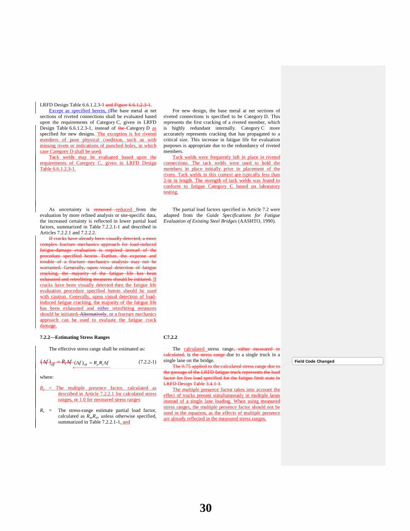
The effective stress range shall be estimated as: ( ) sefff R f∆ = ∆ ( )eff p sf R R f∆ = ∆ (7.2.2-1)
where:
Rp = The multiple presence factor, calculated as described in Article 7.2.2.1 for calculated stress ranges, or 1.0 for measured stress ranges
Rs = The stress-range estimate partial load factor, calculated as RsaRst, unless otherwise specified, summarized in Table 7.2.2.1-1, and
The calculated stress range, either measured or calculated, is the stress range due to a single truck in a single lane on the bridge.
The 0.75 applied to the calculated stress range due to the passage of the LRFD fatigue truck represents the load factor for live load specified for the fatigue limit state in LRFD Design Table 3.4.1-1.
The multiple presence factor takes into account the effect of trucks present simultaneously in multiple lanes instead of a single lane loading. When using measured stress ranges, the multiple presence factor should not be used in the equation, as the effects of multiple presence are already reflected in the measured stress ranges.
Field Code Changed
30
∆f = Measured effective stress range; or 75 percent of thefactored calculated stress range due to the passage of the fatigue truck as specified in LRFD Design Article 3.6.1.4 for Fatigue II Load Combination, or the calculated stress range due to a fatigue truck determined by a truck survey or weigh-in-motion study
The load factor is 0.75 for live load specified for the Fatigue II limit state (finite load-induced fatigue life) in LRFD Design Table 3.4.1-1.
7.2.2.1—Calculating Estimated Stress Ranges
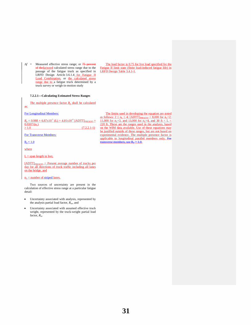
The multiple presence factor Rp shall be calculated
as: For Longitudinal Members: Rp = 0.988 + 6.87x10⁻⁵ (L) + 4.01x10⁻⁶ [ADTT]PRESENT + 0.0107/(nL) ≥ 1.0 (7.2.2.1-1) For Transverse Members: Rp = 1.0 where L = span length in feet, [ADTT]PRESENT = Present average number of trucks per day for all directions of truck traffic including all lanes on the bridge, and nL = number of striped lanes.
The limits used in developing the equation are noted as follows: 2 ≤ nL ≤ 4; [ADTT]PRESENT < 8,000 for nL=2; 11,000 for nL=3, and 13,000 for nL=4, and 30 ft < L < 220 ft. These are the ranges used in the analysis, based on the WIM data available. Use of these equations may be justified outside of these ranges, but are not based on experimental evidence. The multiple presence factor is applicable to longitudinal parallel members only. For transverse members, use RP = 1.0.
Two sources of uncertainty are present in the calculation of effective stress range at a particular fatigue detail: • Uncertainty associated with analysis, represented by
the analysis partial load factor, Rsa, and
• Uncertainty associated with assumed effective truck weight, represented by the truck-weight partial load factor, Rst.
31

Table 7.2.2.1-1—Partial Load Factors: Rsa, Rst, and Rs
Fatigue-Life Evaluation Methods
Analysis Partial Load Factor, Rsa
Truck-Weight Partial Load Factor, Rst
Stress-Range Estimate Partial Load Factor, Rs
a For Evaluation or Minimum Fatigue Life
Stress range by simplified analysis, and truck weight per LRFD Design Article 3.6.1.4
1.0 1.0 1.0
Stress range by simplified analysis, and truck weight estimated through weigh-in-motion study
1.0 0.95 0.95
Stress range by refined analysis, and truck weight per LRFD Design Article 3.6.1.4
0.95 1.0 0.95
Stress range by refined analysis, and truck weight by weigh-in-motion study
0.95 0.95 0.90
Stress range by field-measured strains
N/A N/A 0.85
For Mean Fatigue Life All methods N/A N/A 1.00
a In general, s sa stR R R=
7.2.2.1.1—For the Determination of Evaluation or Minimum Fatigue Life
In the calculation of effective stress range for the
determination of evaluation or minimum fatigue life, the stress-range estimate partial load factor shall be taken as the product of the analysis partial load factor and the truck-weight partial load factor:
s sa stR R R= (7.2.2.1.1-1)
If the effective stress range is calculated through
refined methods of analysis, as defined in LRFD Design Article 4.6.3:
0.95saR = (7.2.2.1.1-2)
otherwise:
1.0saR = (7.2.2.1.1-3) If the effective truck weight is estimated through a
weight-in-motion study at, or near, the bridge:
0.95stR = (7.2.2.1.1-4)
otherwise:
1.0stR = (7.2.2.1.1-5)
32
7.2.2.1.2—For the Determination of Mean Fatigue Life
In the calculation of effective stress range for the
determination of mean fatigue life, the stress-range estimate partial load factor shall be taken as 1.0.
7.2.2.2—Measuring Estimated Stress Ranges C7.2.2.2
The effective stress range may be estimated through
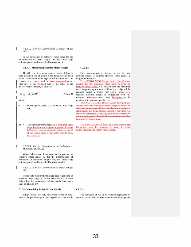
field measurements of strains at the fatigue-prone detail under consideration under typical traffic conditions. The effective stress range shall be taken computed as the cube root of the weighted sum of the cubes of the measured stress ranges, as given in:
( ) ( )1
3 3s i iefff R fΣ∆ = γ ∆ (7.2.2.2-1)
where:
γi = Percentage of cycles at a particular stress range and
∆fi = The particular stress range in a measured stress range histogram of magnitude greater than one half of the constant-amplitude-fatigue-threshold of the fatigue prone detail under consideration, i.e. > ∆FTH/2.
Field measurements of strains represent the most accurate means to estimate effective stress ranges at fatigue-prone details.
The AASHTO LRFD Bridge Design Specifications assume that the maximum stress range is twice the effective stress range. It is unlikely that the maximum stress range during the service life of the bridge will be captured during a limited field-testing measurement session; therefore means to extrapolate from the measured effective stress range histogram to the maximum stress range must be used.
The AASHTO LRFD Bridge Design Specifications assume that the maximum stress range is twice the effective stress range. If the effective truck weight is significantly less than 54 kips, a multiplier more than two should be considered. Similarly, for a measured effective truck weight greater than 54 kips a multiplier less than two would be appropriate.
The lower portion of field measured stress range
histograms must be truncated in order to avoid underestimating the effective stress range.
7.2.2.2.1—For the Determination of Evaluation or Minimum Fatigue Life
Where field-measured strains are used to generate an
effective stress range, Rs, for the determination of evaluation or minimum fatigue life, the stress-range estimate partial load factor shall be taken as 0.85.
7.2.2.2.2—For the Determination of Mean Fatigue Life
Where field-measured strains are used to generate an
effective stress range, Rs, for the determination of mean fatigue life, the stress-range estimate partial load factor shall be taken as 1.0.
7.2.3—Determining Fatigue-Prone Details C7.2.3
Bridge details are only considered prone to load-induced fatigue damage if they experience a net tensile
The multiplier of two in the equation represents the assumed relationship between maximum stress range and
33

stress. Thus, fatigue damage need only be evaluated if, at the detail under evaluation:
( ) - 2 s dead load compressiontensionR f f∆ >
( ) - 2 dead load compressiontensionf f∆ > (7.2.3-1)
effective stress range, as specified in the AASHTO LRFD Bridge Design Specifications.
When measured stress ranges are used to evaluate fatigue life, the multiplier of two in the equation should be reconsidered based upon the discussion of Article C7.2.2.2.
If the effective truck weight is significantly less than 54 kips, a multiplier more than two should be considered. Similarly, for a measured effective truck weight greater than 54 kips a multiplier less than two would be appropriate.
where:
Rs = The stress-range estimate partial load factor, specified in Article 7.2.2 and summarized in Table 7.2.2.1-1
(∆f)tension = Factored tTensile portion of the effective stress range due to the passage of a fatigue truck as specified in Article 7.2.2, and
fdead-load compression = Unfactored compressive stress at the detail
due to dead load
7.2.4—Infinite-Life Check C7.2.4 If:
( ) ( )max THf F∆ ≤ ∆ (7.2.4-1) then:
Y = ∞ (7.2.4-2) where:
(∆f)max = The maximum stress range expected at the fatigue-prone detail, which may be taken as:
• Rp times the factored calculated stress range due to the passage of the fatigue truck as specified in LRFD Design Article 3.6.1.4 for Fatigue I Load Combination
• 2.0(∆f )eff ; for calculated stress range due to a fatigue truck determined by a truck survey or weigh-in-motion study with Rs=1.0
• Larger of maximum (∆fi), 2.0(∆f )eff, or other suitable value; for measured stress ranges with Rs=1.0
Theoretically, a fatigue-prone detail will experience infinite life if all of the stress ranges are less than the constant amplitude fatigue threshold; in other words, if the maximum stress range is less than the threshold.
When measured stress ranges are used to evaluate fatigue life, the multiplier of two in the equation for (∆f )max should be reconsidered based upon the discussion of Article C7.2.2.2.
The load factor is 1.50 for live load specified for the
Fatigue I limit state (infinite load-induced fatigue life) in LRFD Design Table 3.4.1-1.
When measured stress ranges are used to evaluate
fatigue life, the maximum stress range should be taken as the larger value of two times field measured effective stress range or the field measured maximum stress range,
Field Code Changed
34

(∆F)TH = The constant-amplitude fatigue threshold given in LRFD Design Table 6.6.1.2.5-3
Otherwise, the total fatigue life shall be estimated as specified in Article 7.2.5.
unless another suitable value is justified.
7.2.5—Estimating Finite Fatigue Life
7.2.5.1—General C7.2.5.1
Three Four levels of finite fatigue life may be estimated: • The minimum expected fatigue life (which equals
the conservative design fatigue life),
• Evaluation 1 fatigue life (which equals a conservative fatigue life for evaluation),
• The eEvaluation 2 fatigue life (which equals a less conservative fatigue life for evaluation), and
• The mean fatigue life (which equals the statistically most likely fatigue life).
The total finite fatigue life of a fatigue-prone detail,
in years, shall be determined as:
( ) ( )3
365
R
SL eff
R AYn ADTT f
= ∆
[ ]1
3log (1 ) 1365 ( ) [( ) ]
log(1 )
aR
SL effPRESENT
R A g gn ADTT f
Yg
−
+ + ∆ =
+ (7.2.5.1-
1)
Much scatter, or variability, exists in experimentally derived fatigue lives. For design, a conservative fatigue resistance two standard deviations shifted below the mean fatigue resistance or life is assumed. This corresponds to the minimum expected finite fatigue life of this Article. Limiting actual usable fatigue life to this design fatigue life is very conservative and can be costly. As such, means of estimating the two evaluation fatigue life lives and the mean finite fatigue life are also included to aid the evaluator in the decision making. Evaluation 1 is equivalent to the evaluation life in the previous specification, while Evaluation 2 fatigue life provides an additional choice for the user midway between the Evaluation 1 and the mean fatigue life values.
Figure C7.2.5.5-1 may be used to estimate the average number of trucks per day in a single lane averaged over the fatigue life, (ADTT)SL, from the present average number of trucks per day in a single lane, [(ADTT)SL]present, the present age of the bridge, a, and the estimated annual traffic-volume growth rates, g.
Recent research has made it possible to obtain a
closed-form solution for the total finite fatigue life using an estimated traffic growth rate and the present (ADTT)SL. The estimated annual traffic growth rate can be obtained using available information in the agency’s bridge inventory or the NBI. For cases with zero traffic growth, a very small value of g should be selected (less than 0.01%) for use in the expression for Y.
Field Code Changed
35

where:
RR = Resistance factor specified for evaluation, minimum, or mean fatigue life as given in Table 7.2.5.21-1
A = Detail-category constant given in LRFD Design Table 6.6.1.2.5-1
n = Number of stress-range cycles per truck passage estimated according to Article 7.2.5.2
g = Estimated annual traffic-volume growth rate in percentage
a = Present age of the detail in years
[(ADTT)SL]PRESENT
= Present Average average number of trucks per day in a single lane averaged over the fatigue life as specified in LRFD Design Article 3.6.1.4.2
(∆f)eff = The effective stress range as specified in Article 7.2.2
The resistance factors for fatigue life, specified in Table 7.2.5.21-1, represent the variability of the fatigue life of the various detail categories, A through E′. The minimum life, evaluation 1 life and evaluation 2 life fatigue-life curves are shifted from the mean fatigue-life S-N curves in log-log space. Scatter of the fatigue lives at given stress range values from controlled laboratory testing provides statistical information on fatigue behavior of bridge details under cyclic loading. Accordingly, the probability of failure associated with each level of fatigue life, approaches 2 percent, 16 percent, 33 percent and 50 percent for the minimum, evaluation 1, evaluation 2 and mean fatigue lives, respectively. Typically, the minimum life or evaluation 1 life is used to evaluate the fatigue serviceability. If concerns are encountered regarding the computed fatigue serviceability, then the serviceability index can be revised according to Article 7.2.7.2.As the stress-range estimate grows closer and closer to the actual value of stress range, the probability of failure associated with each level of fatigue life approaches two percent, 16 percent, and 50 percent for the minimum, evaluation, and mean fatigue lives, respectively. The minimum and evaluation fatigue-life curves are two and one standard deviations off of the mean fatigue-life S-N curves in log-log space, respectively. Thus, the partial resistance factors for mean and evaluation fatigue life are calculated as raised to the power of twice and one times the standard deviation of the log of experimental fatigue life for each detail category, respectively.
36

Figure C7.2.5.1-1—Lifetime Average Truck Volume for an Existing Bridge
Formatted: Font: (Default)AIPOMA+TimesNewRoman
37
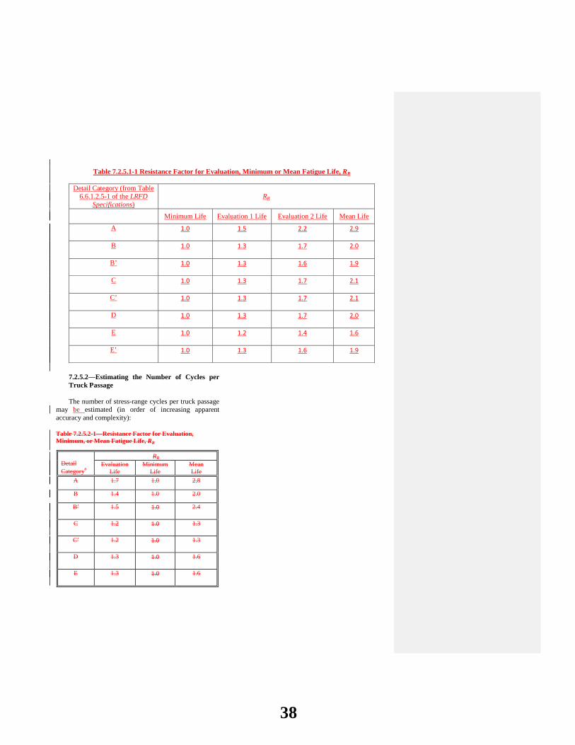
Table 7.2.5.1-1 Resistance Factor for Evaluation, Minimum or Mean Fatigue Life, RR
Detail Category (from Table 6.6.1.2.5-1 of the LRFD
Specifications) RR
Minimum Life Evaluation 1 Life Evaluation 2 Life Mean Life
A 1.0 1.5 2.2 2.9
B 1.0 1.3 1.7 2.0
B’ 1.0 1.3 1.6 1.9
C 1.0 1.3 1.7 2.1
C’ 1.0 1.3 1.7 2.1
D 1.0 1.3 1.7 2.0
E 1.0 1.2 1.4 1.6
E’ 1.0 1.3 1.6 1.9
7.2.5.2—Estimating the Number of Cycles per Truck Passage
The number of stress-range cycles per truck passage
may be estimated (in order of increasing apparent accuracy and complexity):
Table 7.2.5.2-1—Resistance Factor for Evaluation, Minimum, or Mean Fatigue Life, RR
Detail Categorya
RR Evaluation
Life Minimum
Life Mean Life
A 1.7 1.0 2.8
B 1.4 1.0 2.0
B′ 1.5 1.0 2.4
C 1.2 1.0 1.3
C′ 1.2 1.0 1.3
D 1.3 1.0 1.6
E 1.3 1.0 1.6
38
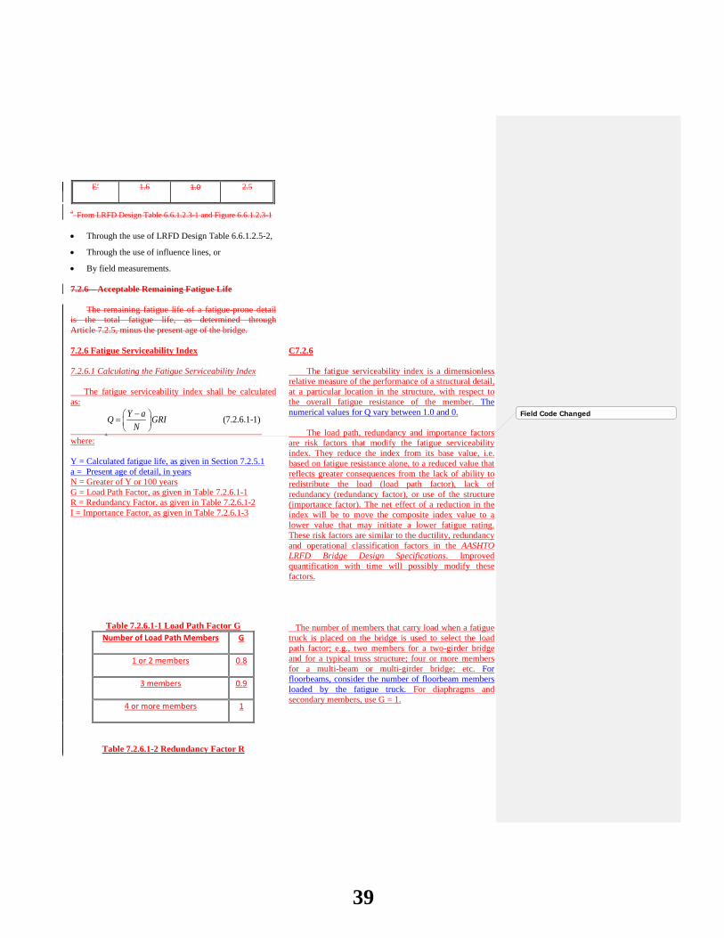
E′ 1.6 1.0 2.5
a From LRFD Design Table 6.6.1.2.3-1 and Figure 6.6.1.2.3-1 • Through the use of LRFD Design Table 6.6.1.2.5-2,
• Through the use of influence lines, or
• By field measurements.
7.2.6—Acceptable Remaining Fatigue Life
The remaining fatigue life of a fatigue-prone detail is the total fatigue life, as determined through Article 7.2.5, minus the present age of the bridge. 7.2.6 Fatigue Serviceability Index 7.2.6.1 Calculating the Fatigue Serviceability Index The fatigue serviceability index shall be calculated as:
(7.2.6.1-1)Y aQ GRI
N− =
where: Y = Calculated fatigue life, as given in Section 7.2.5.1 a = Present age of detail, in years N = Greater of Y or 100 years G = Load Path Factor, as given in Table 7.2.6.1-1 R = Redundancy Factor, as given in Table 7.2.6.1-2 I = Importance Factor, as given in Table 7.2.6.1-3
Table 7.2.6.1-1 Load Path Factor G Number of Load Path Members G
1 or 2 members 0.8
3 members 0.9
4 or more members 1
Table 7.2.6.1-2 Redundancy Factor R
C7.2.6 The fatigue serviceability index is a dimensionless relative measure of the performance of a structural detail, at a particular location in the structure, with respect to the overall fatigue resistance of the member. The numerical values for Q vary between 1.0 and 0. The load path, redundancy and importance factors are risk factors that modify the fatigue serviceability index. They reduce the index from its base value, i.e. based on fatigue resistance alone, to a reduced value that reflects greater consequences from the lack of ability to redistribute the load (load path factor), lack of redundancy (redundancy factor), or use of the structure (importance factor). The net effect of a reduction in the index will be to move the composite index value to a lower value that may initiate a lower fatigue rating. These risk factors are similar to the ductility, redundancy and operational classification factors in the AASHTO LRFD Bridge Design Specifications. Improved quantification with time will possibly modify these factors. The number of members that carry load when a fatigue truck is placed on the bridge is used to select the load path factor; e.g., two members for a two-girder bridge and for a typical truss structure; four or more members for a multi-beam or multi-girder bridge; etc. For floorbeams, consider the number of floorbeam members loaded by the fatigue truck. For diaphragms and secondary members, use G = 1.
Field Code Changed
39
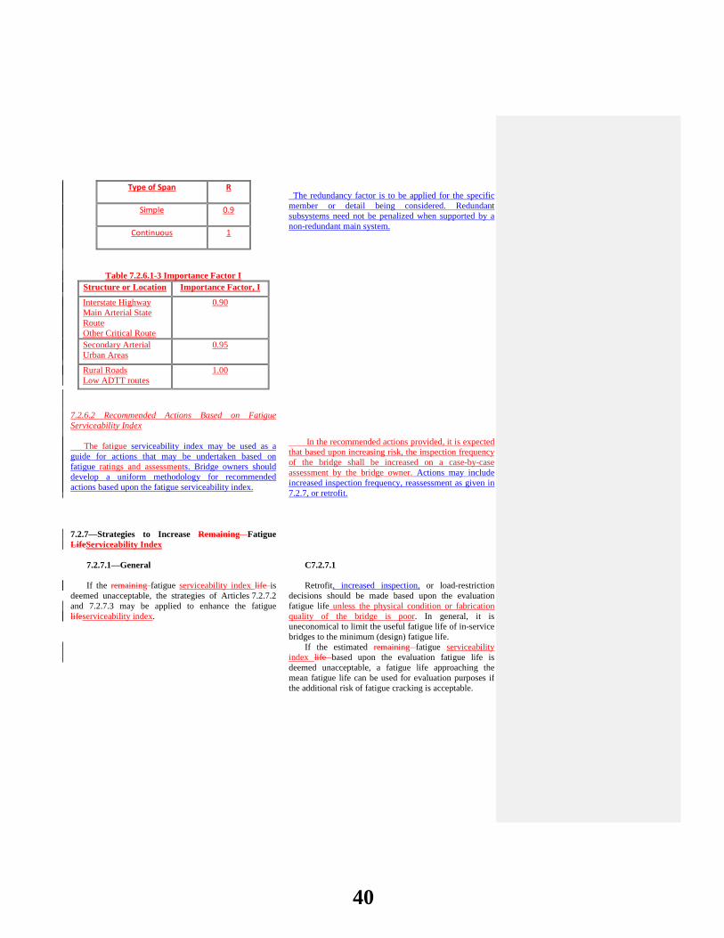
Type of Span R
Simple 0.9
Continuous 1
Table 7.2.6.1-3 Importance Factor I Structure or Location Importance Factor, I
Interstate Highway Main Arterial State Route Other Critical Route
0.90
Secondary Arterial Urban Areas
0.95
Rural Roads Low ADTT routes
1.00
7.2.6.2 Recommended Actions Based on Fatigue Serviceability Index The fatigue serviceability index may be used as a guide for actions that may be undertaken based on fatigue ratings and assessments. Bridge owners should develop a uniform methodology for recommended actions based upon the fatigue serviceability index.
The redundancy factor is to be applied for the specific member or detail being considered. Redundant subsystems need not be penalized when supported by a non-redundant main system. In the recommended actions provided, it is expected that based upon increasing risk, the inspection frequency of the bridge shall be increased on a case-by-case assessment by the bridge owner. Actions may include increased inspection frequency, reassessment as given in 7.2.7, or retrofit.
7.2.7—Strategies to Increase Remaining Fatigue LifeServiceability Index
7.2.7.1—General C7.2.7.1
If the remaining fatigue serviceability index life is
deemed unacceptable, the strategies of Articles 7.2.7.2 and 7.2.7.3 may be applied to enhance the fatigue lifeserviceability index.
Retrofit, increased inspection, or load-restriction decisions should be made based upon the evaluation fatigue life unless the physical condition or fabrication quality of the bridge is poor. In general, it is uneconomical to limit the useful fatigue life of in-service bridges to the minimum (design) fatigue life.
If the estimated remaining fatigue serviceability index life based upon the evaluation fatigue life is deemed unacceptable, a fatigue life approaching the mean fatigue life can be used for evaluation purposes if the additional risk of fatigue cracking is acceptable.
40
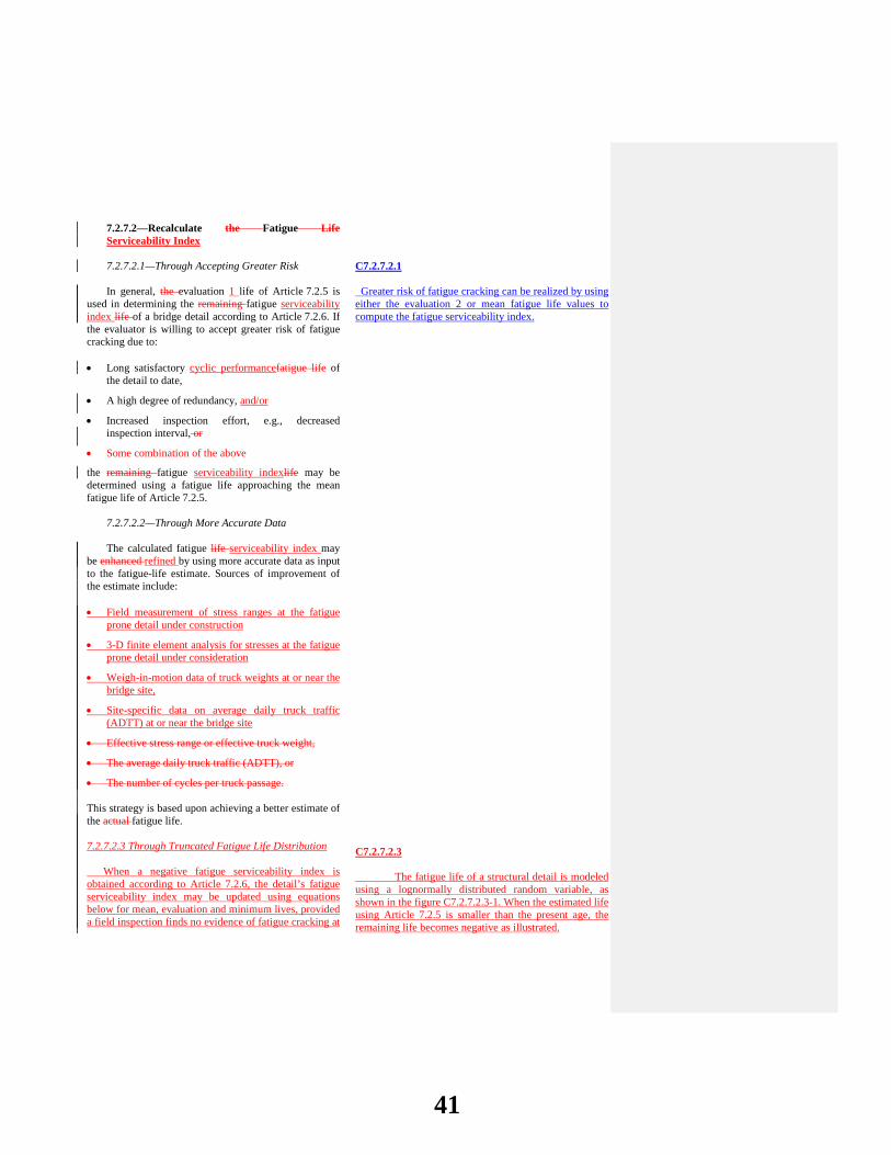
7.2.7.2—Recalculate the Fatigue Life Serviceability Index
7.2.7.2.1—Through Accepting Greater Risk C7.2.7.2.1
In general, the evaluation 1 life of Article 7.2.5 is
used in determining the remaining fatigue serviceability index life of a bridge detail according to Article 7.2.6. If the evaluator is willing to accept greater risk of fatigue cracking due to:
Greater risk of fatigue cracking can be realized by using either the evaluation 2 or mean fatigue life values to compute the fatigue serviceability index.
• Long satisfactory cyclic performancefatigue life of the detail to date,
• A high degree of redundancy, and/or
• Increased inspection effort, e.g., decreased inspection interval, or
• Some combination of the above
the remaining fatigue serviceability indexlife may be determined using a fatigue life approaching the mean fatigue life of Article 7.2.5.
7.2.7.2.2—Through More Accurate Data
The calculated fatigue life serviceability index may
be enhanced refined by using more accurate data as input to the fatigue-life estimate. Sources of improvement of the estimate include: • Field measurement of stress ranges at the fatigue
prone detail under construction
• 3-D finite element analysis for stresses at the fatigue prone detail under consideration
• Weigh-in-motion data of truck weights at or near the bridge site,
• Site-specific data on average daily truck traffic (ADTT) at or near the bridge site
• Effective stress range or effective truck weight,
• The average daily truck traffic (ADTT), or
• The number of cycles per truck passage.
This strategy is based upon achieving a better estimate of the actual fatigue life. 7.2.7.2.3 Through Truncated Fatigue Life Distribution When a negative fatigue serviceability index is obtained according to Article 7.2.6, the detail’s fatigue serviceability index may be updated using equations below for mean, evaluation and minimum lives, provided a field inspection finds no evidence of fatigue cracking at
C7.2.7.2.3 The fatigue life of a structural detail is modeled using a lognormally distributed random variable, as shown in the figure C7.2.7.2.3-1. When the estimated life using Article 7.2.5 is smaller than the present age, the remaining life becomes negative as illustrated.
41
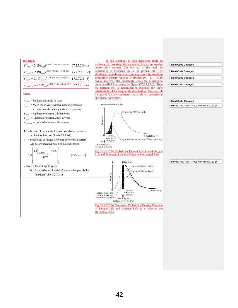
the detail.
( )10.73 [0.18(1 ) ] 0.27' 2.19 7.2.7.2.3 1P Pmean meanY Y e
−Φ − + −= −
( )10.73 [0.12(1 ) ] 0.272' 2.19 7.2.7.2.3 2P P
eval meanY Y e−Φ − + −= −
( )10.73 [0.074(1 ) ] 0.271' 2.19 7.2.7.2.3 3P P
eval meanY Y e−Φ − + −= −
( )10.73 [0.039(1 ) ] 0.27minimum' 2.19 7.2.7.2.3 4P P
meanY Y e−Φ − + −= −
where
eval1
eval
' = Updated mean life in years = Mean life in years without updating based on
no detection of cracking at detail in questionY' = Updated evaluation 1 life in yearsY'
mean
mean
YY
2
minimum
-1
= Updated evaluation 2 life in yearsY' = Updated minimum life in years
= Inverse of the standard normal variable's cumulative probability function (Table 7.2.7.2-1)P = Probab
Φ
( )
ility of fatigue life being shorter than current age before updating based on no crack found
0.272.19
= 7.2.7.2.3 50.73
where a = Present age
mean
aLnY
+
Φ −
in years = Standard normal variable's cumulative probability function (Table 7.2.7.2-1)
Φ
In this situation, if field inspection finds no evidence of cracking, the estimated life is an overly-conservative estimate. The low tail of the total life distribution is truncated up to the present life. The eliminated probability P is computed, and the resulting probability density function is divided by (1 – P) to ensure that the total probability under the distribution curve is still 1.0 as shown in Figure C7.2.7.2.3-2. Then the updated life is determined to maintain the same reliability level for fatigue life distribution. Functions Φ (.) and Φ-1(.) are commonly available in commercial spreadsheet programs.
Fig C7.2.7.2.3-1 Probability Density Function of Fatigue Life and Estimated Life as a Value on Horizontal Axis
Fig C7.2.7.2.3-2 Truncated Probability Density Function of Fatigue Life and Updated Life as a value on the Horizontal Axis
Field Code Changed
Field Code Changed
Field Code Changed
Field Code Changed
Field Code Changed
Formatted: Font: Times New Roman, 10 pt
Formatted: Font: Times New Roman, 10 pt
42
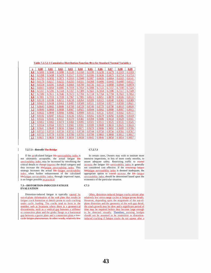
Table 7.2.7.2-1 Cumulative Distribution Function Φ(x) for Standard Normal Variable x
x 0.00 0.01 0.02 0.03 0.04 0.05 0.06 0.07 0.08 0.09 0.0 0.5000 0.5040 0.5080 0.5120 0.5160 0.5199 0.5239 0.5279 0.5319 0.5359 0.1 0.5398 0.5438 0.5478 0.5517 0.5557 0.5596 0.5636 0.5675 0.5714 0.5753 0.2 0.5793 0.5832 0.5871 0.5910 0.5948 0.5987 0.6026 0.6064 0.6103 0.6141 0.3 0.6179 0.6217 0.6255 0.6293 0.6331 0.6368 0.6406 0.6443 0.6480 0.6517 0.4 0.6554 0.6591 0.6628 0.6664 0.6700 0.6736 0.6772 0.6808 0.6844 0.6879 0.5 0.6915 0.6950 0.6985 0.7019 0.7054 0.7088 0.7123 0.7157 0.7190 0.7224 0.6 0.7257 0.7291 0.7324 0.7357 0.7389 0.7422 0.7454 0.7486 0.7517 0.7549 0.7 0.7580 0.7611 0.7642 0.7673 0.7704 0.7734 0.7764 0.7794 0.7823 0.7852 0.8 0.7881 0.7910 0.7939 0.7967 0.7995 0.8023 0.8051 0.8078 0.8106 0.8133 0.9 0.8159 0.8186 0.8212 0.8238 0.8264 0.8289 0.8315 0.8340 0.8365 0.8389 1.0 0.8413 0.8438 0.8461 0.8485 0.8508 0.8531 0.8554 0.8577 0.8599 0.8621 1.1 0.8643 0.8665 0.8686 0.8708 0.8729 0.8749 0.8770 0.8790 0.8810 0.8830 1.2 0.8849 0.8869 0.8888 0.8907 0.8925 0.8944 0.8962 0.8980 0.8997 0.9015 1.3 0.9032 0.9049 0.9066 0.9082 0.9099 0.9115 0.9131 0.9147 0.9162 0.9177 1.4 0.9192 0.9207 0.9222 0.9236 0.9251 0.9265 0.9279 0.9292 0.9306 0.9319 1.5 0.9332 0.9345 0.9357 0.9370 0.9382 0.9394 0.9406 0.9418 0.9429 0.9441 1.6 0.9452 0.9463 0.9474 0.9484 0.9495 0.9505 0.9515 0.9525 0.9535 0.9545 1.7 0.9554 0.9564 0.9573 0.9582 0.9591 0.9599 0.9608 0.9616 0.9625 0.9633 1.8 0.9641 0.9649 0.9656 0.9664 0.9671 0.9678 0.9686 0.9693 0.9699 0.9706 1.9 0.9713 0.9719 0.9726 0.9732 0.9738 0.9744 0.9750 0.9756 0.9761 0.9767 2.0 0.9772 0.9778 0.9783 0.9788 0.9793 0.9798 0.9803 0.9808 0.9812 0.9817 2.1 0.9821 0.9826 0.9830 0.9834 0.9838 0.9842 0.9846 0.9850 0.9854 0.9857
7.2.7.3—Retrofit The Bridge C7.2.7.3
If the recalculated fatigue life serviceability index is not ultimately acceptable, the actual fatigue life serviceability index may be increased by retrofitting the critical details to change improve the detail category and thus increase the lifefatigue serviceability index. This strategy increases the actual life fatigue serviceability index when further enhancement of the calculated lifefatigue serviceability index, through improved input, is no longer possible or practical.
In certain cases, Owners may wish to institute more intensive inspections, in lieu of more costly retrofits, to assure adequate safety. Restricting traffic to extend increase the fatigue life serviceability index is generally not considered cost effective. If the remaining fatigue lifefatigue serviceability index is deemed inadequate, the appropriate option to extend increase the life fatigue serviceability index should be determined based upon the economics of the particular situation.
7.3—DISTORTION-INDUCED FATIGUE EVALUATION
C7.3
Distortion-induced fatigue is typically caused by
out-of-plane deformation of the web plate that results in fatigue crack formation at details prone to such cracking under cyclic loading. The cracks tend to form in the member web at locations where there is a geometrical discontinuity, such as a vertical gap between a stiffener or connection plate and the girder flange or a horizontal gap between a gusset plate and a connection plate.a low-cycle fatigue phenomenon. In other words, relatively few
Often, distortion-induced fatigue cracks initiate after relatively few stress-range cycles at fatigue-prone details. However, depending upon the magnitude of the out-of-plane distortion and the geometry of the web gap detail, the crack growth may be slow and a significant period of time may be required before they become large enough to be detected visually. Therefore, existing bridges should not be assumed to be insensitive to distortion-induced cracking if fatigue cracks do not appear after a
43

stress-range cycles are required to initiate cracking at distortion-induced fatigue-prone details. Distortion-induced fatigue is a stiffness problem (more precisely the lack thereof) versus a load problem.
As such, existing bridges which have experienced many truck passages, if uncracked, may be deemed insensitive to distortion-induced cracking, even under heavier permit loads. 7.3.1 Methods to Assess Distortion-Induced Cracking Out-of-plane distortions caused by truck loading must be accommodated by the regions that contain unsupported web gaps. Fatigue cracks caused by out-of-plane distortions should be repaired when they develop. 7.3.2 Retrofit Options for Distortion-Induced Fatigue Cracking
Retrofit should be considered if distortion-induced cracking has been detected. Two primary retrofit methods are available: softening or stiffening. The softening approach is used to increase the overall flexibility of the detail in question to accommodate the out-of-plane deformations without further cracking. The stiffening approach is used to minimize the local distortion by providing a positive load path for the forces that tend to cause the distortion. In either case, a hole should be drilled at the tip of each crack.
short period of time. Experience has shown that in some cases cracking may not be evident for 10 years after the beginning of service.Distortion-induced cracks have even been discovered on bridges prior to being opened to traffic. C7.3.1
Typically, smaller web gaps are subject to higher
distortion-induced stresses than larger web gaps provided the same demand for the out-of-plane distortion. The demand for out-of-plane distortion is determined by the global behavior of the structural system. Accurate quantification of the stress field in an unsupported web gap detail can be very difficult, even for finite element modeling or field measurement of strains and/or local deformations. This is especially the case when the dimension of the web gap is comparable to the thicknesses of the surrounding plates and the sizes of the connecting welds, resulting in high stress gradients across the web gap.
Even very small distortions can cause high local stresses that may induce fatigue cracking. Often, the fatigue cracks grow in a plane that is parallel to the primary stresses of the member and will slow down or even stop as the web gap becomes more flexible due to the presence of the crack. However, it is possible that the crack may turn and become perpendicular to the primary stress of the member, leading to more rapid crack growth. Therefore, distortion-induced fatigue cracks should be repaired.
C7.3.2 In the softening retrofit, the flexibility of the detail
in question is increased. Drilling holes to eliminate the tip of distortion-induced fatigue cracks will typically increase the local flexibility somewhat. However, the primary method used to increase the flexibility is to increase the size of the web gap. This can be effective since the out-of-plane bending stresses are related to the inverse of the square of the web gap length. One critical issue for this approach is to avoid an excessive increase of out-of-plane deformation resulting from the web gap enlargement. Removal of portions of a stiffener or other plate to increase the size of the web gap will also require removal of the connecting weld in those regions to provide a smooth, flush surface. Non-destructive inspection should be conducted to ensure that no undesirable gouges, notches or discontinuities remain.
44

In the stiffening retrofit, the stiffness of the detail in question is increased to minimize the out-of-plane distortion. Commonly, this will require the addition of a WT section, or a double or single angle section. Drilling retrofit holes to eliminate the tip of any distortion-induced fatigue cracks should be done prior to installation of the retrofit connection element. Typically, the installation of a retrofit element will increase the stiffness and significantly decrease the out-of-plane deformation at the detail. However, the force effect of the retrofit on the primary and secondary members should be considered. One critical issue for this approach is to size the retrofit connection of sufficient thickness and strength for the loading forces to be generated at the new connection.
45
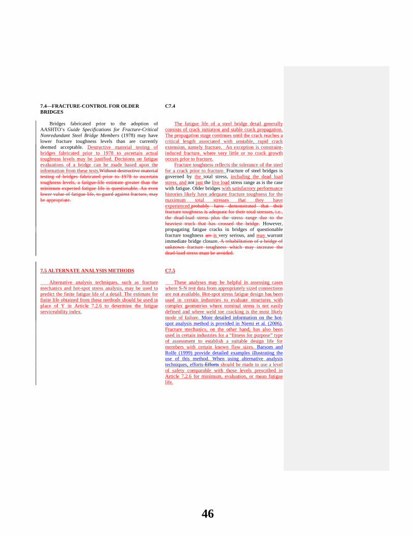
7.4—FRACTURE-CONTROL FOR OLDER BRIDGES
C7.4
Bridges fabricated prior to the adoption of
AASHTO’s Guide Specifications for Fracture-Critical Nonredundant Steel Bridge Members (1978) may have lower fracture toughness levels than are currently deemed acceptable. Destructive material testing of bridges fabricated prior to 1978 to ascertain actual toughness levels may be justified. Decisions on fatigue evaluations of a bridge can be made based upon the information from these tests.Without destructive material testing of bridges fabricated prior to 1978 to ascertain toughness levels, a fatigue-life estimate greater than the minimum expected fatigue life is questionable. An even lower value of fatigue life, to guard against fracture, may be appropriate. 7.5 ALTERNATE ANALYSIS METHODS Alternative analysis techniques, such as fracture mechanics and hot-spot stress analysis, may be used to predict the finite fatigue life of a detail. The estimate for finite life obtained from these methods should be used in place of Y in Article 7.2.6 to determine the fatigue serviceability index.
The fatigue life of a steel bridge detail generally consists of crack initiation and stable crack propagation. The propagation stage continues until the crack reaches a critical length associated with unstable, rapid crack extension, namely fracture. An exception is constraint-induced fracture, where very little or no crack growth occurs prior to fracture.
Fracture toughness reflects the tolerance of the steel for a crack prior to fracture. Fracture of steel bridges is governed by the total stress, including the dead load stress, and not just the live load stress range as is the case with fatigue. Older bridges with satisfactory performance histories likely have adequate fracture toughness for the maximum total stresses that they have experienced.probably have demonstrated that their fracture toughness is adequate for their total stresses, i.e., the dead-load stress plus the stress range due to the heaviest truck that has crossed the bridge. However, propagating fatigue cracks in bridges of questionable fracture toughness are is very serious, and may warrant immediate bridge closure. A rehabilitation of a bridge of unknown fracture toughness which may increase the dead-load stress must be avoided.
C7.5
These analyses may be helpful in assessing cases where S-N test data from appropriately sized connections are not available. Hot-spot stress fatigue design has been used in certain industries to evaluate structures with complex geometries where nominal stress is not easily defined and where weld toe cracking is the most likely mode of failure. More detailed information on the hot-spot analysis method is provided in Niemi et al. (2006). Fracture mechanics, on the other hand, has also been used in certain industries for a “fitness for purpose” type of assessment to establish a suitable design life for members with certain known flaw sizes. Barsom and Rolfe (1999) provide detailed examples illustrating the use of this method. When using alternative analysis techniques, efforts Efforts should be made to use a level of safety comparable with those levels prescribed in Article 7.2.6 for minimum, evaluation, or mean fatigue life.
46

7.57.6—REFERENCES
AASHTO. 1978. Guide Specifications for Fracture-Critical Nonredundant Steel Bridge Members - with interims. American Association of State Highway and Transportation Officials, Washington, DC.
AASHTO. 1990. Guide Specifications for Fatigue Evaluation of Existing Steel Bridges. American Association of State Highway and Transportation Officials, Washington, DC.
AASHTO. 200720102012. AASHTO LRFD Bridge Design Specifications, Fourth SixthFifth Edition, LRFDUS-4-M or LRFDSI-4. American Association of State Highway and Transportation Officials, Washington, DC.
Barsom, J.M. and S.T. Rolfe, 1999. Fracture and Fatigue Control in Structures – Application of Fracture Mechanics. American Society for Testing and Materials, West Coshohocken, PA.
Bowman, M.D., G. Fu, Y.E. Zhou, R.J. Connor,A.A. Godbole, 2012. Fatigue Evaluation of Steel Bridges, NCHRP Report 721. Transportation Research Board, National Research Council, Washington. D.C.
Moses, F., C. G. Schilling, and K. S. Raju. 1987. Fatigue Evaluation Procedures for Steel Bridges, NCHRP Report 299. Transportation Research Board, National Research Council, Washington, DC.
Niemi, E., W. Fricke, and S.J. Maddox, 2006. Fatigue Analysis of Welded Components – Designers Guide to the Structural Hot-Spot Stress Approach, CRC Press, Cambridge, England.
47
2014 AASHTO BRIDGE COMMITTEE AGENDA ITEM: 7 SUBJECT: The Manual for Bridge Evaluation: Section 6, Appendix A, Example A1 (T18-9) TECHNICAL COMMITTEE: T-18 Bridge Management, Evaluation and Rehabilitation
REVISION ADDITION NEW DOCUMENT
DESIGN SPEC CONSTRUCTION SPEC MOVABLE SPEC MANUAL FOR BRIDGE SEISMIC GUIDE SPEC COASTAL GUIDE SPEC
EVALUATION OTHER DATE PREPARED: 12/12/13 DATE REVISED: AGENDA ITEM: Revise Appendix A, Example A1 as shown in Attachment C.
OTHER AFFECTED ARTICLES:None
BACKGROUND:Revisions to MBE Section 7—Fatigue Evaluation of Steel Bridges of the AASHTO Manual for Bridge Evaluation contained in Agenda Item # updates the procedures for fatigue evaluation of steel bridges. Areas that have been improved include methods of estimating total and remaining fatigue life and a new methodology to evaluate fatigue serviceability. The research that proposed these updates to Section 7was performed under NCHRP Project 12-81, “Evaluation of Fatigue on the Serviceability of Highway Bridges”. Load rating example A1 in Appendix A had incorporated a section on fatigue evaluation of a welded cover plate detail consistent with the requirements of Section 7. This example now needs to be updated to reflect the proposed revisions to Section 7, as shown in Attachment B.
ANTICIPATED EFFECT ON BRIDGES:The revision of Section 7 provides improved methods utilizing a reliability-based approach to assess the fatigue behavior of bridges. The proposed revisions to example A1maintains the consistency between the load rating and fatigue evaluation examples and the MBE provisions.
REFERENCES: Bowman, M.D., G. Fu, Y.E. Zhou, R.J. Connor,A.A. Godbole, 2012. Fatigue Evaluation of Steel Bridges, NCHRP Report 721. Transportation Research Board, National Research Council, Washington. D.C.
OTHER: None
48

ATTACHMENT C – 2014 AGENDA ITEM 7 - T -18 (T-18-9)
Recommended Revisions to the AASHTO MBE LRFR Load Rating Example A1
A1—SIMPLE SPAN COMPOSITE STEEL STRINGER BRIDGE
PART A—LOAD AND RESISTANCE FACTOR RATING METHOD
A1A.1.8.3—Fatigue Limit State (6A.6.4.1)
Determine if the bridge has any fatigue-prone details (Category C or lower).
The transverse welds detail connecting the ends of cover plates to the flange are fatigue-prone details. Category E’ details because the flange thicknesss = 0.855 in. is greater than 0.8 in.
LRFD Design Table 6.6.1.2.3-1
If 2Rs(∆f)tension > fdead-load compression, the detail may be prone to fatigue. fdead-load compression = 0 at cover plate at all locations because beam is a simple span and cover plate is
located in the tension zone
7.2.3
∴ must consider fatigue; compute RF for fatigue load for infinite life.
RF = ( )( )
( )( )R DC DC
LL LL IM max
f ff +
− γγ ∆
fR = (∆F)TH
γLL = 0.75 γDC = 0.00 Table 6A.4.2.2-1 Composite section properties without cover plate.
A yyA
∑ ×=
∑ =
( )( ) ( )
( )
8838.26 16.55 7.25 36.72598838.26 7.259
+ × + ×
= 29.65 in. from bottom of flange
Ix = ( )( )( )
( )( )3
2 2
88 7.258896699 38.26 13.10 7.25 7.07
12 9
+ + +
= 17119 in.4
Sb = 317119 577 in.29.65
=
Live Load at Cover Plate Cut-Off (13.5 ft. from centerline of bearing) Fatigue Load: Design truck with a spacing of 30 ft between 32 kip axles. LRFD Design 3.6.1.4.1
and Figure 3.6.1.2.2-1 MLL = (32 kips) (10.69 ft) + (32 kips) (4.46 ft) + (8 kips) (1.56 ft)
= 497 kip-ft = 5967 kip-in. Using influence lines. IM = 15% LRFD Design
49

Table 3.6.2.1-1 MLL + IM = (1.15) (5967) = 6862 kip-in.
Item #1 Revise Article A1A.1.8.3a as follows:
A1A.1.8.3a—Load Distribution for Fatigue
LRFD Design 3.6.1.4.3b The single-lane distribution factor will be used for fatigue. LRFD Design 3.6.1.1.2 Remove multiple presence factor from the single-lane distribution. LRFD Design C3.6.1.1.2
gFatigue = ( )11
1.2 mg
= ( )1 0.461.2
= 0.383 Distributed Live-Load Moment: gMLL + IM = (0.383) (6862)
= 2628 kip-in. Fatigue Load Stress Range:
∆fLL + IM = 2628577
= 4.56 ksi at the cover plate weld Nominal fatigue resistance for infinite life. (∆F)TH = 2.6 ksi for Detail Category E′ LRFD Design
Table 6.6.1.2.5-3 Infinite-Life Fatigue Check: 7.2.4 Rsa = 1.0 stress range by simplified analysis Table 7.2.2.1-1 Rst = 1.0 truck weight per LRFD Design Specifications Rs = Rsa × Rst = 1.0 ∆feff = ( )( )( ) ( )( )1.0 0.75 4.56 3.42 ksis LL LL IMR f +γ ∆ = =
(∆fLL + IM)max = (2.0) (∆feff) = 2.0 (3.42) = 6.84 ksi
7.2.4
RF = ( )
( )TH
LL IM max
Ff +
∆
∆
= 2.6 0.38 1.06.84
= <
50

The detail does not possess infinite fatigue life per LRFD new bridge standards. Evaluate remaining fatigue life using procedures given in Section 7 of this Manual. Infinite-Life Fatigue Check
MBE 7.2.4
ADTT = 1000 Span Length = 65 ft Number of lanes = 2
Rp = 0.988 + 6.87x10⁻⁵ Span Length + 4.01x10⁻⁶ ADTT + 0.0107 / Number of lanes = 0.988 + 6.87x10-5*65+4.01x10-6*1000+0.0107/2 = 1.0018
MBE 7.2.2.1
(∆f)max = (Rp)(∆fFATIGUE I) = (1.0018)(1.50)(4.56) = 6.86 ksi > 2.6 ksi Thus, (∆f)max > (∆F)TH.
The detail does not possess infinite fatigue life. Evaluate fatigue life using procedures given in Section 7 of AASHTO’s The Manual for Bridge Evaluation.
MBE 7.2.4
Item #2 Revise Article A1A.1.8.3b as follows
A1A.1.8.3b—Calculation of Remaining Fatigue Life
Finite life determination:
Y = ( ) ( )
3365
R
SL eff
R A
n ADTT f∆
7.2.5.1
ADTT (one direction) = 1000 ADTTSL = 0.85 (1000) = 850 LRFD Design
Table 3.6.1.4.2-1 Using a two percent growth rate and age of 43 y (2007–1964) Figure C7.2.5.1-1 ADTT multiplier = 1.02 Lifetime average ADTTSL = (1.02) (850) 867 For Category E′ evaluation life: RR = 1.6 Table 7.2.5.2-1 A = 3.9 × 10⁸ ksi3 LRFD Design
Table 6.6.1.2.5-1 n = 1.0 simple span girders with L > 40 ft LRFD Design
Table 6.6.1.2.5-2
51
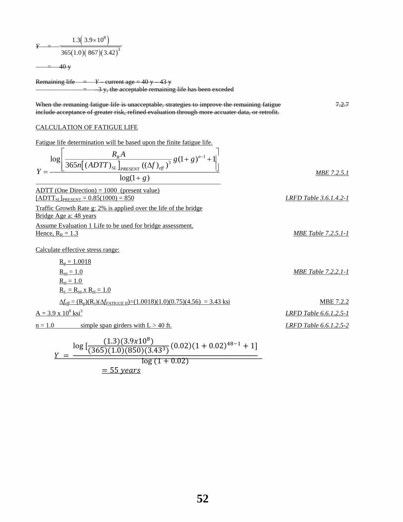
Y = ( )
( )( )( )
8
3
1.3 3.9 10
365 1.0 867 3.42
×
= 40 y Remaining life = Y – current age = 40 y – 43 y = –3 y, the acceptable remaining life has been exceded When the remaning fatigue life is unacceptable, strategies to improve the remaining fatigue include acceptance of greater risk, refined evaluation through more accuater data, or retrofit.
7.2.7
CALCULATION OF FATIGUE LIFE Fatigue life determination will be based upon the finite fatigue life.
[ ]1
3log (1 ) 1365 ( ) (( ) )
log(1 )
aR
SL effPRESENT
R A g gn ADTT f
Yg
−
+ + ∆ =
+
MBE 7.2.5.1
ADTT (One Direction) = 1000 (present value) [ADTTSL]PRESENT = 0.85(1000) = 850
LRFD Table 3.6.1.4.2-1
Traffic Growth Rate g: 2% is applied over the life of the bridge Bridge Age a: 48 years
Assume Evaluation 1 Life to be used for bridge assessment. Hence, RR = 1.3
MBE Table 7.2.5.1-1
Calculate effective stress range:
Rp = 1.0018 Rsa = 1.0 MBE Table 7.2.2.1-1 Rst = 1.0 Rs = Rsa x Rst = 1.0
∆feff = (Rp)(Rs)(∆fFATIGUE II)=(1.0018)(1.0)(0.75)(4.56) = 3.43 ksi MBE 7.2.2
A = 3.9 x 10⁸ ksi3 LRFD Table 6.6.1.2.5-1
n = 1.0 simple span girders with L > 40 ft. LRFD Table 6.6.1.2.5-2
𝑌 = log [ (1.3)(3.9𝑥108)
(365)(1.0)(850)(3.433) (0.02)(1 + 0.02)48−1 + 1]
log (1 + 0.02)
= 55 𝑦𝑒𝑎𝑟𝑠
52
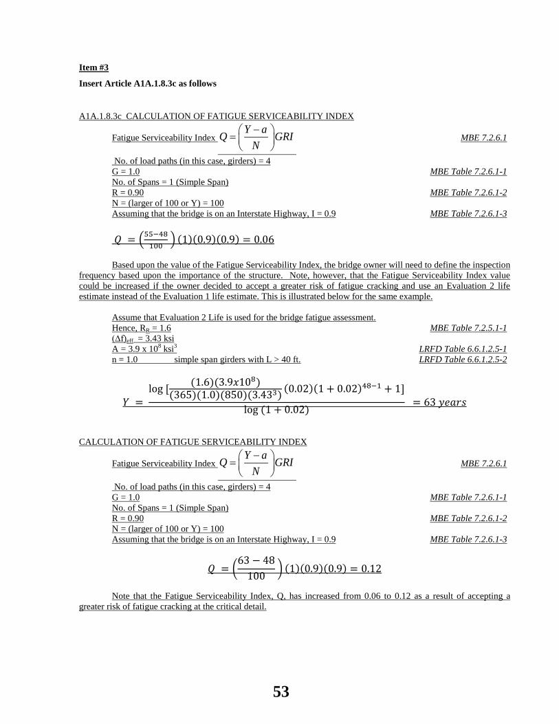
Item #3
Insert Article A1A.1.8.3c as follows
A1A.1.8.3c CALCULATION OF FATIGUE SERVICEABILITY INDEX
Fatigue Serviceability Index Y aQ GRI
N− =
MBE 7.2.6.1
No. of load paths (in this case, girders) = 4 G = 1.0 MBE Table 7.2.6.1-1 No. of Spans = 1 (Simple Span) R = 0.90 MBE Table 7.2.6.1-2 N = (larger of 100 or Y) = 100 Assuming that the bridge is on an Interstate Highway, I = 0.9 MBE Table 7.2.6.1-3
𝑄 = �55−48100
� (1)(0.9)(0.9) = 0.06 Based upon the value of the Fatigue Serviceability Index, the bridge owner will need to define the inspection
frequency based upon the importance of the structure. Note, however, that the Fatigue Serviceability Index value could be increased if the owner decided to accept a greater risk of fatigue cracking and use an Evaluation 2 life estimate instead of the Evaluation 1 life estimate. This is illustrated below for the same example.
Assume that Evaluation 2 Life is used for the bridge fatigue assessment. Hence, RR = 1.6 MBE Table 7.2.5.1-1 (∆f)eff = 3.43 ksi A = 3.9 x 10⁸ ksi3 LRFD Table 6.6.1.2.5-1 n = 1.0 simple span girders with L > 40 ft. LRFD Table 6.6.1.2.5-2
𝑌 = log [ (1.6)(3.9𝑥108)
(365)(1.0)(850)(3.433) (0.02)(1 + 0.02)48−1 + 1]
log (1 + 0.02) = 63 𝑦𝑒𝑎𝑟𝑠
CALCULATION OF FATIGUE SERVICEABILITY INDEX
Fatigue Serviceability Index Y aQ GRI
N− =
MBE 7.2.6.1
No. of load paths (in this case, girders) = 4 G = 1.0 MBE Table 7.2.6.1-1 No. of Spans = 1 (Simple Span) R = 0.90 MBE Table 7.2.6.1-2 N = (larger of 100 or Y) = 100 Assuming that the bridge is on an Interstate Highway, I = 0.9 MBE Table 7.2.6.1-3
𝑄 = �63 − 48
100 � (1)(0.9)(0.9) = 0.12
Note that the Fatigue Serviceability Index, Q, has increased from 0.06 to 0.12 as a result of accepting a
greater risk of fatigue cracking at the critical detail.
53

2014 AASHTO BRIDGE COMMITTEE AGENDA ITEM: 8 SUBJECT: AASHTO Manual for Bridge Element Inspection, 1st Edition, 2012: Subsection 3.1.1 (T18-10) TECHNICAL COMMITTEE: T-18 Bridge Management, Evaluation and Rehabilitation
REVISION ADDITION NEW DOCUMENT
DESIGN SPEC CONSTRUCTION SPEC MOVABLE SPEC MANUAL FOR BRIDGE SEISMIC GUIDE SPEC BRIDGE ELEMENT INSP GUIDE
EVALUATION OTHER Manual for Bridge Element Inspection, 1st Ed. DATE PREPARED: 04/30/14 DATE REVISED: AGENDA ITEM:On Page 3-2, Subsection 3.1.1, and for other elements as shown in Other Effected Articles revise condition state definitions as follows for CS1(Good), CS2 (Fair), and CS3(Poor) for elements having defect 1130 Cracking (RC and Other) and add commentary.
Condition State Definitions
Condition States
1 2 3 4
Defects GOOD FAIR POOR SEVERE
Delamination/Spall/ Patched Area
(1080)
None. Delaminated. Spall 1 in. or less deep or 6 in. or less in diameter. Patched area that is sound.
Spall greater than 1 in. deep or greater than 6 in. diameter. Patched area that is unsound or showing distress. Does not warrant structural review.
The condition warrants a structural review to determine the effect on strength or serviceability of the element or bridge; OR a structural review has been completed and the defects impact strength or serviceability of the element or bridge. Exposed Rebar
(1090) None. Present without
measurable section loss.
Present with measurable section loss but does not warrant structural review.
Efflorescence/Rust Staining (1120)
None. Surface white without build-up or leaching without rust staining.
Heavy build-up with rust staining.
54
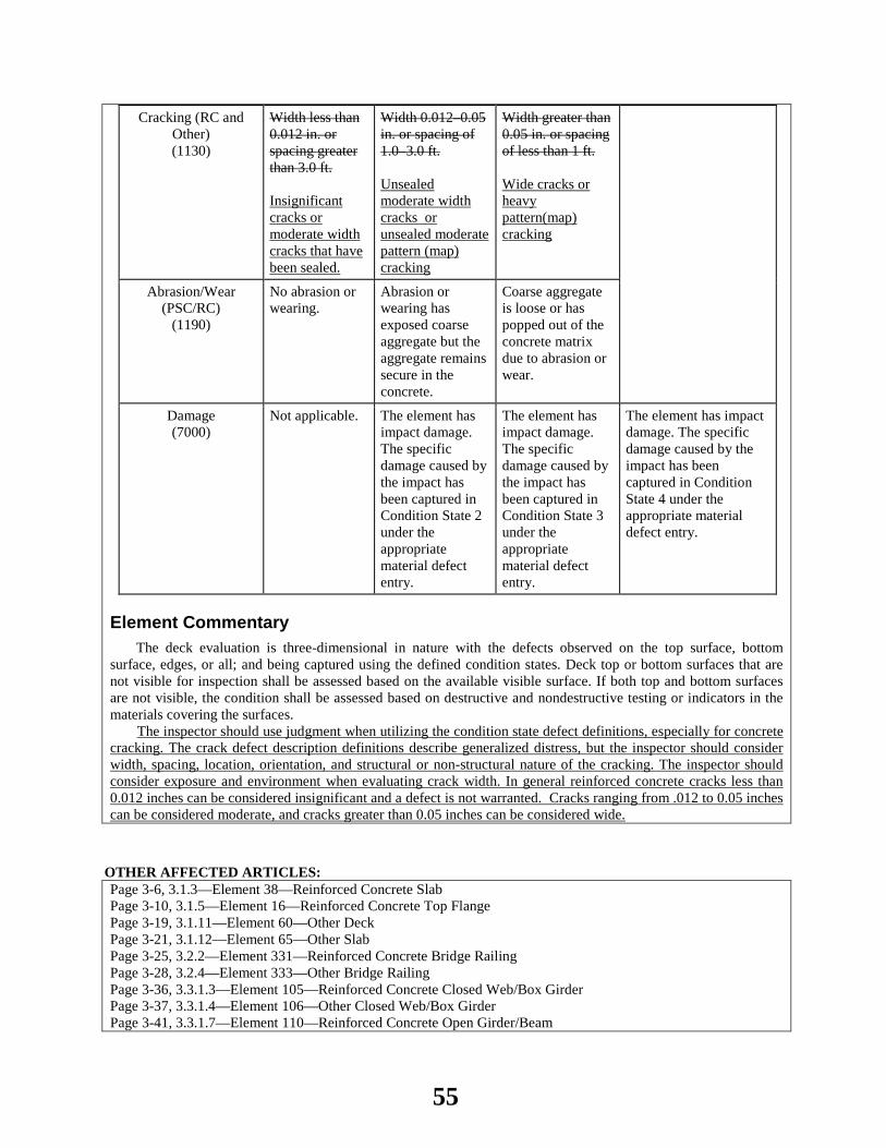
Cracking (RC and Other) (1130)
Width less than 0.012 in. or spacing greater than 3.0 ft. Insignificant cracks or moderate width cracks that have been sealed.
Width 0.012–0.05 in. or spacing of 1.0–3.0 ft. Unsealed moderate width cracks or unsealed moderate pattern (map) cracking
Width greater than 0.05 in. or spacing of less than 1 ft. Wide cracks or heavy pattern(map) cracking
Abrasion/Wear (PSC/RC)
(1190)
No abrasion or wearing.
Abrasion or wearing has exposed coarse aggregate but the aggregate remains secure in the concrete.
Coarse aggregate is loose or has popped out of the concrete matrix due to abrasion or wear.
Damage (7000)
Not applicable. The element has impact damage. The specific damage caused by the impact has been captured in Condition State 2 under the appropriate material defect entry.
The element has impact damage. The specific damage caused by the impact has been captured in Condition State 3 under the appropriate material defect entry.
The element has impact damage. The specific damage caused by the impact has been captured in Condition State 4 under the appropriate material defect entry.
Element Commentary The deck evaluation is three-dimensional in nature with the defects observed on the top surface, bottom
surface, edges, or all; and being captured using the defined condition states. Deck top or bottom surfaces that are not visible for inspection shall be assessed based on the available visible surface. If both top and bottom surfaces are not visible, the condition shall be assessed based on destructive and nondestructive testing or indicators in the materials covering the surfaces.
The inspector should use judgment when utilizing the condition state defect definitions, especially for concrete cracking. The crack defect description definitions describe generalized distress, but the inspector should consider width, spacing, location, orientation, and structural or non-structural nature of the cracking. The inspector should consider exposure and environment when evaluating crack width. In general reinforced concrete cracks less than 0.012 inches can be considered insignificant and a defect is not warranted. Cracks ranging from .012 to 0.05 inches can be considered moderate, and cracks greater than 0.05 inches can be considered wide.
OTHER AFFECTED ARTICLES:Page 3-6, 3.1.3—Element 38—Reinforced Concrete Slab Page 3-10, 3.1.5—Element 16—Reinforced Concrete Top Flange Page 3-19, 3.1.11—Element 60—Other Deck Page 3-21, 3.1.12—Element 65—Other Slab Page 3-25, 3.2.2—Element 331—Reinforced Concrete Bridge Railing Page 3-28, 3.2.4—Element 333—Other Bridge Railing Page 3-36, 3.3.1.3—Element 105—Reinforced Concrete Closed Web/Box Girder Page 3-37, 3.3.1.4—Element 106—Other Closed Web/Box Girder Page 3-41, 3.3.1.7—Element 110—Reinforced Concrete Open Girder/Beam
55

Page 3-44, 3.3.1.9—Element 112—Other Open Girder/Beam Page 3-49, 3.3.2.3—Element 116—Reinforced Concrete Stringer Page 3-52, 3.3.2.5—Element 118—Other Stringer Page 3-58, 3.3.3.3—Element 136—Other Truss Page 3-61, 3.3.3.5—Element 142—Other Arch Page 3-65, 3.3.3.7—Element 144—Reinforced Concrete Arch Page 3-73, 3.3.4.3—Element 155—Reinforced Concrete Floor Beam Page 3-76, 3.3.4.5—Element 157—Other Floor Beam Page 3-98, 3.5.1.2—Element 203—Other Column Page 3-102, 3.5.1.4—Element 205—Reinforced Concrete Column Page 3-110, 3.5.1.8—Element 210—Reinforced Concrete Pier Wall Page 3-112, 3.5.1.9—Element 211—Other Pier Wall Page 3-119, 3.5.2.1—Element 215—Reinforced Concrete Abutment Page 3-125, 3.5.2.4—Element 218—Other Abutments Page 3-130, 3.5.3.1—Element 220—Reinforced Concrete Pile Cap/Footing Page 3-136, 3.5.3.4—Element 227—Reinforced Concrete Pile Page 3-140, 3.5.3.6—Element 229—Other Pile Page 3-144, 3.5.3.9—Element 234—Reinforced Concrete Pier Cap Page 3-147, 3.5.3.11—Element 236—Other Pier Cap Page 3-152, 3.6.2—Element 241—Reinforced Concrete Culvert Page 3-156, 3.6.4—Element 243—Other Culvert Page 3-183, 3.9.2—Element 321—Reinforced Concrete Approach Slab Page D-9, D2.3—Reinforced Concrete (400) Page D-14, D2.5—Other Materials (600)
BACKGROUND:Several states and national inspection trainers have identified that if the existing wording for crack defect definitions is interpreted literally, bridge elements that would have previously been rated in good or fair condition could be downgraded to poor condition. Guidance was also requested for the effect sealing cracks have on condition rating and how pattern and map cracking is to be rated. Wording was also added to provide guidance that the portion of the element in Condition State 1 (Good) for cracking is insignificant and does not require a specific material defect. The commentary emphasizes for concrete cracking inspector judgment needs to be utilized to arrive at an appropriate condition rating. Values for minor, moderate, and wide crack sizes have been moved to the commentary.
ANTICIPATED EFFECT ON BRIDGES:The updated defect definitions will allow inspectors to use judgment to place that portion of the element in good, fair, and poor condition states in accordance with training and nationally accepted bridge preservation practice.
REFERENCES: Bridge Inspectors Reference Manual
OTHER: None
56
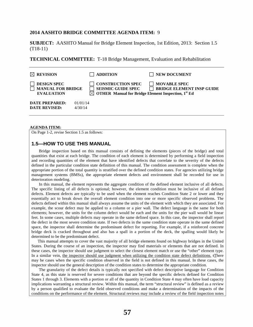
2014 AASHTO BRIDGE COMMITTEE AGENDA ITEM: 9 SUBJECT: AASHTO Manual for Bridge Element Inspection, 1st Edition, 2013: Section 1.5 (T18-11) TECHNICAL COMMITTEE: T-18 Bridge Management, Evaluation and Rehabilitation
REVISION ADDITION NEW DOCUMENT
DESIGN SPEC CONSTRUCTION SPEC MOVABLE SPEC MANUAL FOR BRIDGE SEISMIC GUIDE SPEC BRIDGE ELEMENT INSP GUIDE
EVALUATION OTHER Manual for Bridge Element Inspection, 1st Ed DATE PREPARED: 01/01/14 DATE REVISED: 4/30/14 AGENDA ITEM:On Page 1-2, revise Section 1.5 as follows:
1.5—HOW TO USE THIS MANUAL
Bridge inspection based on this manual consists of defining the elements (pieces of the bridge) and total quantities that exist at each bridge. The condition of each element is determined by performing a field inspection and recording quantities of the element that have identified defects that correlate to the severity of the defects defined in the particular condition state definition of this manual. The condition assessment is complete when the appropriate portion of the total quantity is stratified over the defined condition states. For agencies utilizing bridge management systems (BMSs), the appropriate element defects and environment shall be recorded for use in deterioration modeling.
In this manual, the element represents the aggregate condition of the defined element inclusive of all defects. The specific listing of all defects is optional; however, the element condition must be inclusive of all defined defects. Element defects are typically to be used when the element reaches Condition State 2 or lower and they essentially act to break down the overall element condition into one or more specific observed problems. The defects defined within this manual shall always assume the units of the element with which they are associated. For example, the scour defect may be applied to a column or a pier wall. The defect language is the same for both elements; however, the units for the column defect would be each and the units for the pier wall would be linear feet. In some cases, multiple defects may operate in the same defined space. In this case, the inspector shall report the defect in the most severe condition state. If two defects in the same condition state operate in the same defined space, the inspector shall determine the predominant defect for reporting. For example, if a reinforced concrete bridge deck is cracked throughout and also has a spall in a portion of the deck, the spalling would likely be determined to be the predominant defect. This manual attempts to cover the vast majority of all bridge elements found on highway bridges in the United States. During the course of an inspection, the inspector may find materials or elements that are not defined. In these cases, the inspector should use judgment to select the closest element match or use the “other” element type. In a similar vein, the inspector should use judgment when utilizing the condition state defect definitions. tThere may be cases when the specific condition observed in the field is not defined in this manual. In these cases, the inspector should use the general description of the condition states to determine the appropriate condition.
The granularity of the defect details is typically not specified with defect descriptive language for Condition State 4, as this state is reserved for severe conditions that are beyond the specific defects defined for Condition States 1 through 3. Elements with a portion or all of the quantity in Condition State 4 may often have load capacity implications warranting a structural review. Within this manual, the term “structural review” is defined as a review by a person qualified to evaluate the field observed conditions and make a determination of the impacts of the conditions on the performance of the element. Structural reviews may include a review of the field inspection notes
57

and photographs, review of as-built plans, or analysis as deemed appropriate to evaluate the performance of the element. Agencies may establish additional guidance to aid the inspector in determining the field circumstances where structural review is warranted, taking into consideration the education, training, and experience of their inspection staff.
OTHER AFFECTED ARTICLES:None
BACKGROUND:Great effort was made to describe all defect condition states, however, there will always be exceptions and interpretations that require inspector judgment. The proposed language emphasizes that inspector judgment is needed to appropriately assign condition state ratings.
ANTICIPATED EFFECT ON BRIDGES:This change will provide flexibility and consistent guidance for rating the condition of elements in accordance with state safety inspection and bridge preservation practice.
REFERENCES: None
OTHER: None
58

2014 AASHTO BRIDGE COMMITTEE AGENDA ITEM: 10 SUBJECT: AASHTO Manual for Bridge Element Inspection, 1st Edition, 2013: Appendix D, Section D1 (T18-12) TECHNICAL COMMITTEE: T-18 Bridge Management, Evaluation and Rehabilitation
REVISION ADDITION NEW DOCUMENT
DESIGN SPEC CONSTRUCTION SPEC MOVABLE SPEC MANUAL FOR BRIDGE SEISMIC GUIDE SPEC BRIDGE ELEMENT INSP GUIDE
EVALUATION OTHER Manual for Bridge Element Inspection, 1st Ed. DATE PREPARED: 04/30/14 DATE REVISED: AGENDA ITEM:Revise the 1st paragraph on Page D-1as follows:
MATERIALS AND DEFECTS BY MATERIAL TYPE
This Appendix describes the element materials defined for this manual and the defects that may be observed for each condition state. Included are individual materials, such as reinforced and prestressed concrete, steel, timber, masonry, and other materials; and element types that are made of mixed materials or are not material-based, including joints, protective coatings, wearing surfaces, and deck protection systems. For each material type, the defects are identified with a unique defect code and conditions are described for each state. The primary intent of this Appendix is to provide a roadmap of defined defects for each material, without considering the specific elements constructed of the material. Defect identification codes are provided for reference consistent with Appendix E. Article D1 provides a list of the defects crosstabulated with the materials for which the defects are defined. Defect condition state descriptions are detailed in Article D2. Figure D-1 presents the information in graphical form. The purpose of material defects is to detail the type of distress to the parent element for management and tracking purposes. Listing material defects is optional for the bridge owner. Because Condition State 1 quantifies the portion of the element in good condition, element defects for this condition state typically are not recorded.
OTHER AFFECTED ARTICLES:None
BACKGROUND:Material defects can be listed to better define the overall condition ratings of the parent element. The proposed language provides guidance to bridge inspectors on how to use material defects, emphasizing that a material defect typically is not listed for Condition State 1 (Good).
ANTICIPATED EFFECT ON BRIDGES:This change will provide guidance that will make recording of material defects more efficient in accordance with an agencies bridge management practice.
59

REFERENCES: None
OTHER: None
60

2014 AASHTO BRIDGE COMMITTEE AGENDA ITEM: 11 SUBJECT: Manual for Bridge Element Inspection, 1st Edition: Section 3.3.1.2, 3.3.1.3, and 3.3.1.4 Closed Web Box Girder Quantity Calculation Correction (T18-13) TECHNICAL COMMITTEE: T-18 Bridge Management, Evaluation, and Rehabilitation
REVISION ADDITION NEW DOCUMENT
DESIGN SPEC CONSTRUCTION SPEC MOVABLE SPEC MANUAL FOR BRIDGE SEISMIC GUIDE SPEC BRIDGE ELEMENT INSP GUIDE
EVALUATION OTHER Manual for Bridge Element Inspection, 1st Ed. DATE PREPARED: 4/29/14 DATE REVISED: AGENDA ITEM:Item #1 Section 3.3.1.2-Element 104-Prestressed Concrete Closed Web/Box Girder Revise the text following Quantity Calculation: Number of girders multiplied by the span length. Sum of all the length of each box girder section. This quantity can be determined by counting the visible web faces, dividing by two, and then multiplying by the appropriate length of the box section. Item #2 Section 3.3.1.3-Element 105-Reinforced Concrete Closed Web/Box Girder Revise the text following Quantity Calculation: Number of girders multiplied by the span length. Sum of all the length of each box girder section. This quantity can be determined by counting the visible web faces, dividing by two, and then multiplying by the appropriate length of the box section. Item #3 Section 3.3.1.4-Element 106-Other Closed Web/Box Girder Revise the text following Quantity Calculation: Number of girders multiplied by the span length. Sum of all the length of each box girder section. This quantity can be determined by counting the visible web faces, dividing by two, and then multiplying by the appropriate length of the box section.
OTHER AFFECTED ARTICLES:None
BACKGROUND:The AASHTO Bridge Element Inspection Manual, 1st Ed was approved by AASHTO in June of 2013. This manual contains the bridge inspection elements that are to be collected by the agencies performing element inspection and by the Federal Highway Administration for all National Highway System bridge inspections beginning October 1, 2014. The published manual is not consistent in the method defined to determine to total quantity of closed web box girder elements. The manual contains four closed web box girder elements (102 Steel, 104 Prestressed Concrete,
61

105 Reinforced Concrete, and 106 Other Closed Web Box Girder). The steel closed web box girder quantity calculation method correctly calls for the quantity to be determined as follows: "Sum of all the length of each box girder section. This quantity can be determined by counting the visible web faces, dividing by two, and then multiplying by the appropriate length of the box section". The prestressed concrete, reinforced concrete and other closed web box girder quantity calculation methods are not accurately defined as: "Number of girders multiplied by the span length" This ballot item would change the method of determining the total quantity for elements 104,105 and 106.
ANTICIPATED EFFECT ON BRIDGES:Many agencies are preparing to begin element inspections in accordance with the 2013 AASHTO Bridge Element Inspection Manual. For agencies that have not begun their inspections, this change will have no significant impact other than to ensure consistency in how closed web box girders quantities are reported. For agencies that have already begun inspections using the 2013 manual, this change could cause the agency to revise the quantity for closed web box girders to be consistent with this ballot item. The necessary changes, if any, could be made during the next scheduled inspection of the bridge.
REFERENCES: AASHTO Bridge Element Inspection Manual (1st Edition, 2013)
OTHER: None
62

2014 AASHTO BRIDGE COMMITTEE AGENDA ITEM: 12 SUBJECT: LRFD Bridge Design Specifications: Section 3, Article 3.4.1 TECHNICAL COMMITTEE: T-15 Substructures and Retaining Walls
REVISION ADDITION NEW DOCUMENT
DESIGN SPEC CONSTRUCTION SPEC MOVABLE SPEC MANUAL FOR BRIDGE SEISMIC GUIDE SPEC BRIDGE ELEMENT INSP GUIDE
EVALUATION OTHER DATE PREPARED: 1/15/14 DATE REVISED: AGENDA ITEM: Item #1 In Article 3.4.1, revise Table 3.4.1-1 as follows: Table 3.4.1-1—Load Combinations and Load Factors
Load Combination Limit State
DC DD DW EH EV ES EL PS CR SH
LL IM CE BR PL LS WA WS WL FR TU TG SE
Use One of These at a Time
EQ BL IC CT CV Extreme Event I
γp 1.0
γEQ γEQ
1.00 — — 1.00 — — — 1.00 — — — —
(Rest of table remains unchanged)
Item #2
In the commentary to Article 3.4.1, add the following to the bullet list as bullets 1 and 2:
The design objective is life safety, i.e., noncollapse of the structure. Inelastic behavior such as spalling of concrete and bending of steel members is expected. In most cases the risk doesn’t warrant the expense of designing for elastic behavior so long as vertical-load-carrying capacity is maintained for service-level loads.
Prior to 2014, these Specifications used a value for γp greater than 1.0. This practice went against the intended philosophy behind the Extreme Event Limit State. A more conservative design is attained by increasing the hazard and using ductile detailing, rather than increasing γp, i.e., force effects due to permanent loads.
OTHER AFFECTED ARTICLES:None
63
BACKGROUND:Strength limit state factors for permanent loads, p, have been calibrated to a target reliability, , with a value between 3 and 3.5. The associated level of safety, approximately a 1-in-5000 chance of exceedence--is not appropriate for Extreme Events as it contradicts the intent as described in Article 1.3.2.5. Furthermore, unneeded complexity is added when using a value other than 1.0 and/or different values are used for maximum/minimum loads. The force-based seismic methodology in Section 4 of the AASHTO LRFD Specifications, does not necessarily lead to more conservatively designed columns and superstructures when using a value for p greater than 1.0. A more conservative seismic design is appropriately achieved by using a combination of higher ground motion, ductile detailing, and ample seat dimensions for girders. For foundations, p as currently specified for Extreme Event I--is not appropriate for downdrag and liquefaction analysis. The Commentary to Article 11.5.6 points out that “static loading cannot be separated from the seismic loading (in analysis of earth retaining systems), other than by artificial means through subtracting the static earth pressure from the total earth pressure calculated for seismic loading.”
ANTICIPATED EFFECT ON BRIDGES:None
REFERENCES: None
OTHER: The T-5 Committee has had involvement in the development of this agenda item and concurs with making this change for Extreme Event I, and the development of this agenda item has also been coordinated with the chair of the T-3 committee.
64
2014 AASHTO BRIDGE COMMITTEE AGENDA ITEM: 13 SUBJECT: LRFD Bridge Design Specifications: Section 11, Article C11.5.2 TECHNICAL COMMITTEE: T-15 Substructures and Retaining Walls
REVISION ADDITION NEW DOCUMENT
DESIGN SPEC CONSTRUCTION SPEC MOVABLE SPEC MANUAL FOR BRIDGE SEISMIC GUIDE SPEC BRIDGE ELEMENT INSP GUIDE
EVALUATION OTHER DATE PREPARED: 12/24/13 DATE REVISED: AGENDA ITEM:Revise the last paragraph in Article C11.5.2 as follows:
MSE walls can tolerate larger total and differential vertical deflections than rigid walls. The amount of total and differential vertical deflection that can be tolerated depends on the wall facing material, configuration and timing of facing construction. A cast-in-place facing has the same vertical deformation limitations as the more rigid retaining wall systems. However, an MSE wall with a cast-in-place facing can be specified with a waiting period before the cast-in-place facing is constructed so that vertical (as well as horizontal) deformations have time to occur. An MSE wall with welded wire or geosynthetic facing can tolerate the most deformation. An MSE wall with multiple precast concrete panels cannot tolerate as much vertical deformation as flexible welded wire or geosynthetic facings because of potential damage to the precast panels and unsightly panel separation. The deformation tolerance of other MSE wall facing systems, such as precast concrete panels and dry cast concrete blocks, depends on the spacing or cushioning provided between the facing elements and their dimensions, and guidance is provided in Article C11.10.4.1.
OTHER AFFECTED ARTICLES:None
BACKGROUND:Article C11.5.2 as currently written gives no guidance on how to consider deformation characteristics during MSE wall design. The proposed change preserves the current discussion of deformation characteristics and refers the designer to Article C11.10.4.1 where the necessary guidance is provided.
ANTICIPATED EFFECT ON BRIDGES:None
REFERENCES: None
65

OTHER: None
66
2014 AASHTO BRIDGE COMMITTEE AGENDA ITEM: 14 SUBJECT: LRFD Bridge Design Specifications: Section 11, Article 11.5.4.2 TECHNICAL COMMITTEE: T-15 Substructures and Retaining Walls
REVISION ADDITION NEW DOCUMENT
DESIGN SPEC CONSTRUCTION SPEC MOVABLE SPEC MANUAL FOR BRIDGE SEISMIC GUIDE SPEC BRIDGE ELEMENT INSP GUIDE
EVALUATION OTHER DATE PREPARED: 12/24/13 DATE REVISED: AGENDA ITEM:
In Article 11.5.4.2, add the following to the end of the bullet list: Walls have significant slopes above or below the wall, unless seismic analysis is conducted on the slope. A
significant slope for seismic considerations shall be taken as a slope above the wall or in front of the wall face below the wall which exceeds - θ, where θ = tan-1(kh) and kh = 0.5As. However, if the slope is stabilized to resist the design earthquake, no seismic design of the wall is required, provided it meets the other requirements specified in this Article.
OTHER AFFECTED ARTICLES:None
BACKGROUND:The T-15 committee has received input from several well respected consultants and academics regarding the lack of a caveat addressing the slope above or below a wall that is otherwise allowed to not be designed for seismic loading under the provisions in this article. Furthermore, the NCHRP Report that was used as the basis for the no seismic analysis option (NCHRP Report 611) did include a caveat regarding the slope above the wall. However, the way it was written had short-comings that, at the time, limited its ability to be implemented in the AASHTO specifications. Since that time, a task force, consisting of academics, consultants, and industry with wall expertise, under the auspices of the T-15 Technical Committee and the FHWA has developed a more workable approach to address this issue. AASHTO allows the option to disregard a design check for seismic stability for retaining walls when the acceleration As is less than 0.4g, but no caveats are provided with regard to the slope above the wall and immediately below the wall. However for walls which include a steep slope above or below the wall, this option should be limited to those with stable slopes under static and seismic loads. For example, a 2H:1V slope is stable under static conditions if the soil has a friction angle of 34 deg. When this statically stable slope is subjected to a 0.2g acceleration this slope would be unstable and could fail, creating a high risk situation. This ballot item addresses this design consideration and the safety of the combined structure.
ANTICIPATED EFFECT ON BRIDGES:None
67

REFERENCES: None
OTHER: None
68

2014 AASHTO BRIDGE COMMITTEE AGENDA ITEM: 15 SUBJECT: LRFD Bridge Design Specifications: Section 11, Article C11.5.6 TECHNICAL COMMITTEE: T-15 Substructures and Retaining Walls
REVISION ADDITION NEW DOCUMENT
DESIGN SPEC CONSTRUCTION SPEC MOVABLE SPEC MANUAL FOR BRIDGE SEISMIC GUIDE SPEC BRIDGE ELEMENT INSP GUIDE
EVALUATION OTHER DATE PREPARED: 12/24/13 DATE REVISED: AGENDA ITEM:
Item #1 In Article C11.5.6, revise the 2nd bullet and 4th paragraph as follows: • Transient Loads LS = live load surcharge WA = water load and stream pressure
The subscripts V and H in Figure C11.5.6-4 denote vertical and horizontal components, respectively, of each force. Loads due to water and stream pressure are not shown in these figures. However, the load factor WA as specified in Table 3.4.1-1 is always 1.0. Design specifications to account for the destabilizing effect caused by the presence of water are provided in Article 3.11.3. Item #2 In Article C11.5.6, replace Figures C11.5.6-1, C11.5.6-2 and C11.5.6-4 as follows:
69
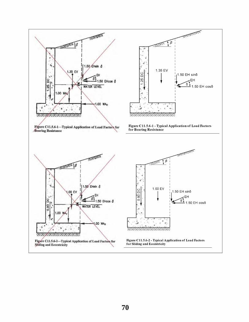
70
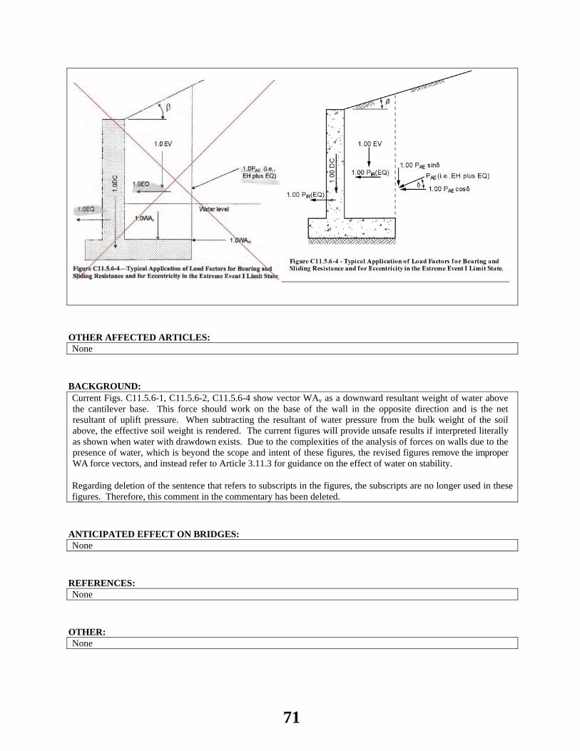
OTHER AFFECTED ARTICLES:None
BACKGROUND:Current Figs. C11.5.6-1, C11.5.6-2, C11.5.6-4 show vector WAv as a downward resultant weight of water above the cantilever base. This force should work on the base of the wall in the opposite direction and is the net resultant of uplift pressure. When subtracting the resultant of water pressure from the bulk weight of the soil above, the effective soil weight is rendered. The current figures will provide unsafe results if interpreted literally as shown when water with drawdown exists. Due to the complexities of the analysis of forces on walls due to the presence of water, which is beyond the scope and intent of these figures, the revised figures remove the improper WA force vectors, and instead refer to Article 3.11.3 for guidance on the effect of water on stability. Regarding deletion of the sentence that refers to subscripts in the figures, the subscripts are no longer used in these figures. Therefore, this comment in the commentary has been deleted.
ANTICIPATED EFFECT ON BRIDGES:None
REFERENCES: None
OTHER: None
71

2014 AASHTO BRIDGE COMMITTEE AGENDA ITEM: 16 SUBJECT: LRFD Bridge Design Specifications: Section 11, Article C11.10.6.4.2a TECHNICAL COMMITTEE: T-15 Substructures and Retaining Walls
REVISION ADDITION NEW DOCUMENT
DESIGN SPEC CONSTRUCTION SPEC MOVABLE SPEC MANUAL FOR BRIDGE SEISMIC GUIDE SPEC BRIDGE ELEMENT INSP GUIDE
EVALUATION OTHER DATE PREPARED: 12/24/13 DATE REVISED: AGENDA ITEM: In Article C11.10.6.4.2a, delete the “I” designations for the test methods in the 4th paragraph and add the following after the 4th paragraph:
Recommended test methods for soil chemical property determination include AASHTO T 289 I for pH, AASHTO T 288 I for resistivity, AASHTO T 291 I for chlorides and AASHTO T 290 I for sulfates.
Resistivity at saturation is the basis for the sacrificial thicknesses specified in this article. Resistivity should be determined under the most adverse condition (i.e., a saturated state) in order to obtain a resistivity that is independent of seasonal and other variations in soil-moisture content (Elias, et al. 2009). AASHTO T 288 measures resistivity of a soil at various moisture contents up to saturation and reports the minimum obtained resistivity.
OTHER AFFECTED ARTICLES:None
BACKGROUND:Regarding the “I” designations for the test methods listed in the third paragraph, these are no longer interim test procedures and the “I” designation has been dropped from the test designation. The proposed commentary (new fourth paragraph) explains that resistivity measured at saturation is the basis for the sacrificial thicknesses used in the Specifications. The recommendation to test in a saturated state is explained in Elias, et al. (2009).
ANTICIPATED EFFECT ON BRIDGES:None
72

REFERENCES: Elias, V., Fishman, K. L., Christopher, B. R., and Berg, R. R. 2009. Corrosion/Degradation of Soil Reinforcements for Mechanically Stabilized Earth Walls and Reinforced Soil Slopes, FHWA-NHI-09-087, Federal Highway Administration.
OTHER: None
73

2014 AASHTO BRIDGE COMMITTEE AGENDA ITEM: 17 SUBJECT: LRFD Bridge Design Specifications: Section 11, Article C11.10.6.4.2a TECHNICAL COMMITTEE: T-15 Substructures and Retaining Walls
REVISION ADDITION NEW DOCUMENT
DESIGN SPEC CONSTRUCTION SPEC MOVABLE SPEC MANUAL FOR BRIDGE SEISMIC GUIDE SPEC BRIDGE ELEMENT INSP GUIDE
EVALUATION OTHER DATE PREPARED: 12/24/13 DATE REVISED: AGENDA ITEM: Revise the 2nd bullet in Article C11.10.6.4.2a as follows:
The MSE wall has a metallic or wire mesh facing, or the metallic soil reinforcement is continuous, forming an electrically conductive circuit along the wall length, and the wall will be exposed to stray currents such as from nearby underground power lines or adjacent electric railways,
OTHER AFFECTED ARTICLES:None
BACKGROUND:Article C11.10.1 correctly states, "All available data indicates that corrosion in MSE walls is not accelerated by stray currents from electric rail lines due to the discontinuity of the earth reinforcements in a direction parallel to the source of the stray current." This statement is supported by the reference cited in Article C11.10.1. Both steel strip and steel bar mat MSE soil reinforcements are discrete elements which do not accumulate stray currents. However, connecting them to a metallic or wire mesh facing, or electrically conductive facing panel reinforcement, creates a condition where stray current accumulation may occur. Therefore, it is appropriate to state that these sacrificial thickness requirements are not applicable when reinforcements are connected to metallic or wire mesh facing, or otherwise can create an electrically conductive path parallel to the source of the stray currents. As currently written, Article C11.10.6.2.4a conflicts with Article C11.10.1. Article C11.10.6.2.4a needs the added text shown above to clarify exactly when stray currents may be a concern.
ANTICIPATED EFFECT ON BRIDGES:None
74

REFERENCES: None
OTHER: None
75

2014 AASHTO BRIDGE COMMITTEE AGENDA ITEM: 18 SUBJECT: LRFD Bridge Design Specifications: Section 11, Article C11.10.6.4.2a TECHNICAL COMMITTEE: T-15 Substructures and Retaining Walls
REVISION ADDITION NEW DOCUMENT
DESIGN SPEC CONSTRUCTION SPEC MOVABLE SPEC MANUAL FOR BRIDGE SEISMIC GUIDE SPEC BRIDGE ELEMENT INSP GUIDE
EVALUATION OTHER DATE PREPARED: 12/24/13 DATE REVISED: AGENDA ITEM: In Article C11.10.6.4.2a, add the following to the end of the 8th paragraph:
Corrosion-resistant coatings should generally be limited to galvanization. Hot-dip galvanization shall be applied after fabrication of the reinforcement into its final configuration.
OTHER AFFECTED ARTICLES:None
BACKGROUND:The added text assures that metallic soil reinforcements are fabricated into their final configuration prior to hot-dip galvanizing. This requirement ensures the safety of structures and compliance with good reinforcement fabrication and coating practice.
ANTICIPATED EFFECT ON BRIDGES:None
REFERENCES: None
OTHER: None
76

2014 AASHTO BRIDGE COMMITTEE AGENDA ITEM: 19 SUBJECT: LRFD Bridge Construction Specifications: New Section TECHNICAL COMMITTEE: T-15 Substructures and Retaining Walls
REVISION ADDITION NEW DOCUMENT
DESIGN SPEC CONSTRUCTION SPEC MOVABLE SPEC MANUAL FOR BRIDGE SEISMIC GUIDE SPEC BRIDGE ELEMENT INSP GUIDE
EVALUATION OTHER DATE PREPARED: 1/9/14 DATE REVISED: AGENDA ITEM:Incorporate Attachment A as a new section of the Bridge Construction Specifications.
OTHER AFFECTED ARTICLES:None
BACKGROUND:Currently, the LRFD Construction Specifications do not address micropiles. This new section will provide construction specifications for micropiles in the LRFD format.
ANTICIPATED EFFECT ON BRIDGES:None
REFERENCES: None
OTHER: None
77
ATTACHMENT A – 2014 AGENDA ITEM 19 - T-15
SECTION 33
MICROPILES
1
33.1 DESCRIPTION This work shall consist of furnishing and
constructing micropile foundations of the type and dimensions designated in the contract documents and these specifications. This specification also covers providing test piles and performing load tests.
C33.1 The term “micropiles” as used in this section means
a small (generally 4” to 12”) diameter bored, cast-in-place composite pile, in which the applied loads are resisted by steel reinforcement, cement grout and frictional grout-to-ground bond.
Type A micropiles are constructed by placing a neat cement grout or sand-cement grout in the pile under a gravity head only.
Type B micropiles are constructed by injecting a neat cement or sand-cement grout under pressure (typically 0.07 to 0.15 ksi) into the drilled hole while the temporary drill pipe/casing or auger is withdrawn.
Type C micropiles are grouted as for Type A, followed 15 to 25 minutes after primary grouting by injection of additional grout under pressure (typically greater than 0.15 ksi) via a preplaced sleeved grout tube.
Type D micropiles are grouted similar to Type C, but the primary grout is allowed to harden before injecting the secondary grout under pressure (typically 0.3 to 1.2 ksi) with a packer to achieve treatment of specific pile intervals or material horizons. Several phases of injection are possible at selected horizons. There is usually an interval of at least 24 hours between successive phases.
Type E micropiles are constructed by drilling with grout injection through a continuous-thread, hollow-core steel bar. The grout injection serves to flush cuttings, achieve grout penetration into the ground and stabilize the drill hole. Often the initial grout has a higher water to cement ratio and is then replaced with thicker structural grout near the completion of drilling.
Primary grout is a Portland-cement based grout injected into the micropile hole before or after reinforcement installation. Primary grout provides direct load transfer along the micropile to the surrounding ground.
Post grouting is the injection of additional grout into the load transfer length of the micropile after hardening of primary grout, also known as regrouting or secondary grouting.
33.2 SUBMITTALS
33.2.1 Construction Submittals
Working drawings and relevant structural and geotechnical design calculations prepared by the Contractor for the planned micropile system or systems shall be submitted for review and approval prior to the start of construction.
78

SECTION 33: MICROPILES 2
A detailed description of the construction procedures shall be submitted for review, including a schedule of major required equipment resources, and drilling and grouting procedures.
The working drawings shall include micropile installation details giving:
Micropile type, number, location and pattern Micropile batter and orientation Micropile factored design load Maximum deflection of piles at factored design
load Type and size of reinforcing steel Details of central reinforcing steel centralizers Minimum total bond length Total micropile length Tip elevation The proposed mix design for the cement grout. The proposed test results for the cement grout Grouting volumes and maximum pressures Micropile top connection details Micropile cut-off elevation Anticipated ground conditions
Shop drawings shall be submitted for review and approval for all structural steel, including micropile components, and corrosion protection system.
For steel pipe used as permanent pipe/casing, or core steel, a minimum of two representative coupon tests or mill certifications shall be submitted on each truckload delivered to the project. Certified mill test reports for the reinforcing steel shall be submitted for record purposes as the materials are delivered. The ultimate strength, yield strength, elongation, and chemical analyses shall be included.
Typically the pipe suppliers and thread fabricators perform unique coupon tests for each truckload of new “Mill Secondary” pipe delivered from the pipe manufacturers. A truckload is defined as up to 44,000 lbs.
The Contractor shall submit the grout mix designs, including details of all materials to be incorporated, and the procedure for mixing and placing the grout for approval. The submittal shall include certified test results verifying the acceptability of the proposed grout mix designs.
79
SECTION 33: MICROPILES 3 The Contractor shall submit for review and
approval, detailed plans for the method proposed for testing of micropiles prior to any testing. The plans shall include all necessary drawings and details to clearly describe the test method and equipment proposed.
The Contractor shall submit for review and acceptance the proposed micropile load testing procedure. The testing procedure shall be provided in accordance with project specified schedules. The micropile verification load testing procedure shall be in general conformance with the latest versions of ASTM D1143 and/or ASTM D3689 ), and shall indicate the minimum following information:
Type and accuracy of apparatus for measuring
load Type and accuracy of apparatus for applying
load Type and accuracy of apparatus for measuring
the pile deformation Type and capacity of reaction load system,
including sealed design drawings Calibration reports for hydraulic jack and load
and deformation devices
The Contractor shall submit calibration reports for each test jack, pressure gauge, load cell and master pressure gauge to be used. The calibration tests shall be performed by an independent testing laboratory. Calibration of pressure gauges shall be within six months prior to the date submitted. Testing shall not commence until these calibrations have been approved.
All Contractor construction submittals shall be submitted at least four (4) weeks prior to the start of micropile construction. The Contractor shall submit the number of copies required by the contract documents of the required construction submittals for acceptance by the Engineer. Work shall not begin until the appropriate submittals have been approved in writing.
80
SECTION 33: MICROPILES 4
33.2.2 Installation Records As a minimum, the installation records shall be
submitted within 24 hours after each pile installation is completed: As a minimum, the records shall include the following:
Pile drilling duration, rate, and observations Description of soil and rock encountered Approximate final tip elevation Cut-off elevation Nominal resistance Description of unusual behavior/conditions Deviations from planned parameters Grout pressures attained (where applicable)
including target pressures and pressures attained
Grout volumes pumped Pile materials and dimensions Load test records, analysis and details Project information, pile location (or ID
number), inspector name, drill method, drill rig operator
In addition, as-built drawings showing the locations
of micropiles, their depths and inclination, and the details of their composition shall be submitted.
33.3 MATERIALS
33.3.1 Water Water for mixing grout shall be potable, clean and
free from substances that may be in any way deleterious to grout or steel. If water is not potable, it shall be tested in accordance with AASHTO T26 for acceptability.
33.3.2 Admixtures Admixtures shall conform to the requirements of
AASHTO M194. Expansive admixtures shall only be added to grout used for filling sealed encapsulations or micropile top connections. Admixtures shall be compatible with the grout and mixed in accordance with the manufacturer’s recommendations. Their use will only be permitted after field tests on fluid and set grout properties. Admixtures with chlorides shall not be permitted. Accelerators shall not be permitted.
Admixtures that control bleed, improve flowability, reduce water content, and retard set may be used in the grout with prior written approval by the Engineer.
33.3.3 Cement All cement shall be Portland cement conforming to
AASHTO M85 Type I, Type II, Type III or Type V, and shall be the product of one manufacturer. If the brand or type of cement is changed during a project, additional grout mix tests shall be conducted to ensure consistency of quality and performance in situ.
81

SECTION 33: MICROPILES 5
33.3.4 Fillers Inert fillers such as sand may be used in the grout in
special situations with prior written approval by the Engineer.
C33.3.4 Special situations may include the presence of large
voids in the ground or when grout take and travel must be limited.
33.3.5 Bar Reinforcement Reinforcing steel shall be either: 1. Solid deformed bars conforming to AASHTO
M31, Grade 60 or Grade 75, or AASHTO M275, Grade 150; or
2. Continuous-thread, hollow-core steel bars (hollow injection rods) conforming to the quality, ductility and deformation requirements of AASHTO M31, Grade 60, Grade 75, Grade 85, Grade 95, or Grade 150.
Bar couplers, if required, shall meet the requirements specified in Article 5.11.3 of the AASHTO LRFD Bridge Design Specifications.
C33.3.5 Larger bars than listed in AASHTO M31 with higher
yield strength may also be used, provided they meet the quality, ductility and deformation requirements of AASHTO M31.
33.3.6 Pipe/Casing If pipe or casing is required to support loads or
reduce deflection, the permanent steel pipe/casing shall meet the tensile requirements of API 5L Grade X52 or better or API 5 CT Grade N80 or better.
Pipe/casing shall be either:
C33.3.6
1. New “Mill Secondary” steel pipe/casing without Mill Certification, provided it is free from defects (dents, cracks, tears) and has a minimum of two unique coupon tests per truckload, or
2. “Prime” steel pipe/casing meeting the requirements of API 5L Grade X52 or better or API 5CT Grade N80 or better (API, 1998).
Coupon testing shall meet the requirements of
ASTM A 370 REV A. If welding of high strength steel pipe/casing is
required, a welding procedure conforming to AWS D1.1 Structural Welding Code-Steel specifications and/or recommendations shall be submitted for review and written approval by the Engineer, prior to any welding operation.
Pipe/casing splices or threads shall develop the required nominal strength of the pile cross section and shall provide proper alignment so that no eccentricity or angle occurs between the axes of the two lengths spliced.
It is commonplace in the micropile industry to utilize “Mill Secondary” (also referred to as “Structural Grade”) steel pipe/casing as an economical means to satisfy the structural requirements of the design and installation. It should be noted that on Federal-Aid highway construction projects it is the Contractor’s responsibility to comply with the provisions of Buy America when selecting materials for the project, which can be more complicated for “Mill Secondary” material than for new “Prime”.
82
SECTION 33: MICROPILES 6
33.3.7 Plates and Shapes Structural steel plates and shapes for pile top
attachments shall conform to AASHTO M183, Grade 36 or AASHTO M223 Grade 50 as specified in the contract documents or on the working drawings.
33.3.8 Centralizers Centralizers shall be fabricated from plastic or
material that is non-detrimental to the reinforcing steel. Wood shall not be used.
Centralizers shall provide for the grout cover specified in Article 33.4.1 and shall permit the free flow of grout without misalignment of the reinforcement.
33.3.9 Corrosion Protection Coating requirements shall be as shown on the
Drawings. If epoxy coating is used, the minimum thickness of
electrostatically applied coating in reinforcing steel shall be 0.007 in. Epoxy coating shall be in accordance with ASTM A775/AASHTO M284 (ASTM, 2006b; AASHTO) or ASTM A934 (ASTM, 2006b). Bend test requirements shall be waived. Epoxy coating shall be factory applied only; on site epoxy coating shall not be permitted, except for minor field touch up. Any field touch up shall be completed per manufacturer’s specifications.
Galvanization shall not be allowed as a means of corrosion protection.
C33.3.9 Coatings are typically not applied to pipe/casing
because the coating may be damaged or removed during casing advancement by drilling.
Sacrificial steel may be used in design of the pile and bearing plates, subject to approval by the Engineer.
Epoxy coating thickness in excess of 0.007 in. may result in problems with connection of bar and hardware resulting from inability to thread couplers and nuts onto bars.
33.4 CONSTRUCTION
33.4.1 Installation Restrictions on drill methods or installation
procedures shall be as specifically defined in the Project Specifications or Drawings.
The micropile installation technique and sequence shall be consistent with the geotechnical, logistical, environmental, and load carrying conditions of the project. The micropile contractor shall select the drilling method and the grouting procedures used for the installation of the micropiles.
C33.4.1
The drilling equipment, methods and sequence shall be suitable for drilling through the conditions to be encountered, with minimal disturbance to these conditions or any overlying or adjacent structure or service.
The borehole must be open to the defined nominal diameter, full length, and prior to placing grout and reinforcement unless the installation is completed by grouting through hollow injection rods.
Water, polymer slurries, and compressed air are typical micropile hole flushing media. Air should be used with caution when in the vicinity of existing structures or services and in granular soils below the water table.
The requirement for an open borehole of defined nominal diameter may be met in stable, competent materials without the need for temporary borehole support. Often, some form of borehole wall support will be required for all or part of the pile length. Such methods include temporary steel pipe/casing, hollow stem augers, or the use of a hole-stabilizing drilling fluid (including grout) provided it has no deleterious effect on geotechnical bond development.
All installation techniques shall be determined and scheduled such that there will be no interconnection or damage to previously installed piles.
83
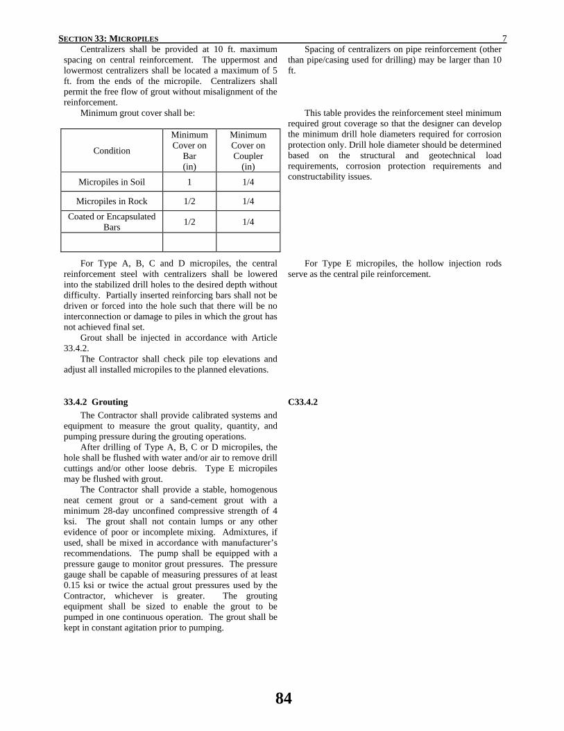
SECTION 33: MICROPILES 7 Centralizers shall be provided at 10 ft. maximum
spacing on central reinforcement. The uppermost and lowermost centralizers shall be located a maximum of 5 ft. from the ends of the micropile. Centralizers shall permit the free flow of grout without misalignment of the reinforcement.
Spacing of centralizers on pipe reinforcement (other than pipe/casing used for drilling) may be larger than 10 ft.
Minimum grout cover shall be:
Condition Minimum Cover on
Bar (in)
Minimum Cover on Coupler
(in)
Micropiles in Soil 1 1/4
Micropiles in Rock 1/2 1/4 Coated or Encapsulated
Bars 1/2 1/4
This table provides the reinforcement steel minimum required grout coverage so that the designer can develop the minimum drill hole diameters required for corrosion protection only. Drill hole diameter should be determined based on the structural and geotechnical load requirements, corrosion protection requirements and constructability issues.
For Type A, B, C and D micropiles, the central reinforcement steel with centralizers shall be lowered into the stabilized drill holes to the desired depth without difficulty. Partially inserted reinforcing bars shall not be driven or forced into the hole such that there will be no interconnection or damage to piles in which the grout has not achieved final set.
Grout shall be injected in accordance with Article 33.4.2.
The Contractor shall check pile top elevations and adjust all installed micropiles to the planned elevations.
For Type E micropiles, the hollow injection rods serve as the central pile reinforcement.
33.4.2 Grouting The Contractor shall provide calibrated systems and
equipment to measure the grout quality, quantity, and pumping pressure during the grouting operations.
After drilling of Type A, B, C or D micropiles, the hole shall be flushed with water and/or air to remove drill cuttings and/or other loose debris. Type E micropiles may be flushed with grout.
The Contractor shall provide a stable, homogenous neat cement grout or a sand-cement grout with a minimum 28-day unconfined compressive strength of 4 ksi. The grout shall not contain lumps or any other evidence of poor or incomplete mixing. Admixtures, if used, shall be mixed in accordance with manufacturer’s recommendations. The pump shall be equipped with a pressure gauge to monitor grout pressures. The pressure gauge shall be capable of measuring pressures of at least 0.15 ksi or twice the actual grout pressures used by the Contractor, whichever is greater. The grouting equipment shall be sized to enable the grout to be pumped in one continuous operation. The grout shall be kept in constant agitation prior to pumping.
C33.4.2
84
SECTION 33: MICROPILES 8 The grout shall be injected from the lowest point of
the drill hole (by tremie methods) until clean, pure grout flows from the top of the micropile. The tremie grout may be pumped through grout tubes, hollow stem augers, or drill rods. Subsequent to tremie grouting, all grouting operations associated with, for example, extraction of drill pipe/casing and pressure grouting, must ensure complete continuity of the grout column. The use of compressed air to directly pressurize the fluid grout is not permissible. The grout pressures and grout takes shall be controlled to prevent excessive heave in soil or fracturing of soil or rock formations. The entire pile shall be grouted to the design cut-off level.
Upon completion of grouting of Type A and B piles, the grout tube may remain in the hole, but it shall be filled with grout. For Type C and D piles, post-grout tubes shall be installed prior to the tremie grouting.
Grout within the micropiles shall be allowed to attain the minimum design strength prior to being loaded.
If the Contractor uses a post-grouting system, all relevant details including grouting pressure, volume, location and mix design, shall be submitted as part of Article 33.2.1.
Drilling with grout may be considered as meeting the tremie grout requirement, provided that the grout spoils at the completion of grouting meet the grout design strength.
85
SECTION 33: MICROPILES 9
33.4.3 Pile Splices Pile splices shall be constructed to develop the
required factored design strength of the pile cross section. Lengths of pipe/casing and reinforcing steel to be
spliced shall be secured in proper alignments and in such a manner that no eccentricity between the axis of the two lengths spliced or angle between them results.
C33.4.3
Casing joints must be carefully and properly aligned to ensure the threaded joints thread together correctly and cross threading is avoided, which may damage casing joints. When proper threading is verified, the casing can be spun tight so the shoulders of adjoining pieces of casing butt against one another tightly.
For reinforcing steel that is spliced, or coupled, the bars and couplers should be tightened in accordance with the manufacturer’s recommendations.
33.4.4 Tolerances Centerline of piling shall not be more than 3 in. from
indicated plan location. Pile-hole alignment of vertical piles shall be within
2% of design alignment. Pile-hole alignment of piles inclined up to 1:6 shall
be within 4% of design alignment. Pile-hole alignment of piles inclined greater than 1:6
shall be within 7% of design alignment. Top elevation of pile shall be within + 1 in. to – 2 in.
of the design vertical elevation. Centerline of core reinforcement shall not be more
than 3/4 in. from centerline of piling.
C33.4.4 These are maximum tolerances for control of
construction.
86
SECTION 33: MICROPILES 10
33.5 LOAD TESTING 33.5.1 General
Pile load tests shall be performed to verify the
adequacy of the design and construction of the pile system.
C33.5.1 Micropiles are field tested to verify that the
micropile design loads can be carried without excessive movements. In addition, testing is used to verify the adequacy of the Contractor’s drilling, installation, and grouting operations prior to and during construction of production piles. Therefore the soil/rock conditions, as well as the method, equipment and operator used for installing production piles must be similar to those used for installing test piles.
Micropile testing is conducted by incrementally loading (and if specified, unloading) the pile and measuring the movement of the pile head at each load increment. Typically, the pile head movement reading is recorded just after the next load increment has been applied. The loading increments, the time that each load increment is held and the number of measurements for each load increment are determined by the type of test being performed and will be specified in the contract documents. If not specified, recommended practice is to obtain a pile-head movement reading just after the load has been applied, and a second reading after the load has been maintained for a sufficient amount of time to ensure that pile-head movement has stabilized.
The total number of load tests, maximum test load capacities and load test schedules will vary based on ground type, pile ultimate capacity, type of loading (e.g., axial, lateral or cyclic), structure sensitivity and Owner/Contractor Experience.
In creep susceptible soils, Extended Creep Tests beyond the tests described herein should be based on Sabatini, et al. (2005) and as described on the Drawings or in the Project Specifications.
33.5.2 Verification Testing The number of test piles, their location, acceptable
load and movement criteria, and the type(s) of loading direction shall be as identified in the contract documents.
The micropile load test results shall verify the suitability of the design and installation methods, and shall be reviewed and accepted by the Engineer prior to the Contractor’s initiation of production micropile installation.
The drilling and grouting methods, pipe/casing and other reinforcement details, and depth of embedment for the test pile(s) shall be identical to the production piles, except where approved otherwise by the Engineer.
C33.5.2
87
SECTION 33: MICROPILES 11 The tested micropiles shall be loaded to 150% of the
factored design load (FDL). The jack shall be positioned at the beginning of the test such that the unloading and repositioning of the jack during the test will not be required. Piles shall be tested under compression loads prior to testing under tension loads. An Alignment Load (AL) may be applied to the pile prior to setting the movement recording devices. This Alignment Load shall be no more than 0.04 FDL. Dial gauges shall be zeroed at the first setting of AL.
Verification pile load tests are typically performed on sacrificial test piles to verify the adequacy of the design of the pile system, and the proposed construction procedures prior to installation of production piles.
The load tested piles should be of the same design as the production piles for the most meaningful results. If the maximum test load exceeds the structural yield load of the pile, the pipe/casing wall thickness and/or bar size may be increased for the test pile; this will result in a decrease in the elastic pile deflection, which may then be estimated by calculation. Alternatively, the bond length may be shortened and the test load reduced when approved by the Engineer.
Axial pile load tests shall be made by loading the micropile in the steps shown in Table 1 and recording the head movement at each step.
For sacrificial test piles, further load cycles may be conducted to failure.
The cyclic test procedure is similar to ASTM D1143 (ASTM, 2006d). This loading method permits fundamental analysis of load test performance because it allows elastic and permanent movements to be studied separately, which can reduce shear/bond strengths to residual values due to continued alternating extension and compression.
Measurement of pile movement shall be obtained at each increment. The load hold period for creep test at 0.975FDL measurement shall start as soon as the test load is applied and shall be recorded at 1 minute, 2, 3, 4, and 5, and 10 minutes (load cycle maxima only).
The acceptance criteria for micropile verification load tests shall be:
1. The pile shall sustain the compression and tension
design loads (0.75 FDL) with no more than the specified permissible total vertical movement at the top of the pile as measured relative to the top of the pile prior to the start of testing. If an Alignment Load is used, then the allowable movement will be reduced by multiplying by a factor of [(0.75 FDL - AL)/0.75 FDL].
2. Test piles shall have a creep rate at the end of the 0.975 FDL increment that is not greater than 0.04 in./log cycle time (1 to 10 minutes) or 0.08 in./log cycle time (6 to 60 minutes) and has a linear or decreasing creep rate.
3. Failure does not occur by 1.50 FDL. Failure is defined as a slope of the load versus deflection curve (at end of increment) exceeding 0.025 in./kip.
The adjustment for allowable movement with an
Alignment Load conservatively accounts for the movement needed to reach AL.
For compression piles with diameters greater than 10 inches and tested in compression, the acceptance criteria may be amended as suggested in AASHTO LRFD Bridge Design Specification Article 10.9.3.5.4.
88
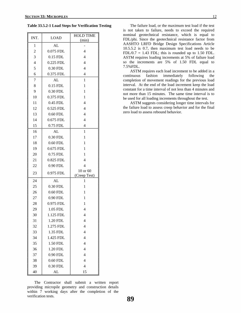
SECTION 33: MICROPILES 12
Table 33.5.2-1 Load Steps for Verification Testing
INT. LOAD HOLD TIME (min)
1 AL - 2 0.075 FDL 4 3 0.15 FDL 4 4 0.225 FDL 4 5 0.30 FDL 4 6 0.375 FDL 4 7 AL 1 8 0.15 FDL 1 9 0.30 FDL 1
10 0.375 FDL 1 11 0.45 FDL 4 12 0.525 FDL 4 13 0.60 FDL 4 14 0.675 FDL 4 15 0.75 FDL 4 16 AL 1 17 0.30 FDL 1 18 0.60 FDL 1 19 0.675 FDL 1 20 0.75 FDL 1 21 0.825 FDL 4 22 0.90 FDL 4
23 0.975 FDL 10 or 60 (Creep Test)
24 AL 1 25 0.30 FDL 1 26 0.60 FDL 1 27 0.90 FDL 1 28 0.975 FDL 1 29 1.05 FDL 4 30 1.125 FDL 4 31 1.20 FDL 4 32 1.275 FDL 4 33 1.35 FDL 4 34 1.425 FDL 4 35 1.50 FDL 4 36 1.20 FDL 4 37 0.90 FDL 4 38 0.60 FDL 4 39 0.30 FDL 4 40 AL 15
The failure load, or the maximum test load if the test
is not taken to failure, needs to exceed the required nominal geotechnical resistance, which is equal to FDL/phi. Since the geotechnical resistance factor from AASHTO LRFD Bridge Design Specifications Article 10.5.5.2 is 0.7, then maximum test load needs to be FDL/0.7 = 1.43 FDL; this is rounded up to 1.50 FDL. ASTM requires loading increments at 5% of failure load so the increments are 5% of 1.50 FDL equal to 7.5%FDL.
ASTM requires each load increment to be added in a continuous fashion immediately following the completion of movement readings for the previous load interval. At the end of the load increment keep the load constant for a time interval of not less than 4 minutes and not more than 15 minutes. The same time interval is to be used for all loading increments throughout the test.
ASTM suggests considering longer time intervals for the failure load to assess creep behavior and for the final zero load to assess rebound behavior.
The Contractor shall submit a written report
providing micropile geometry and construction details within 7 working days after the completion of the verification tests.
89
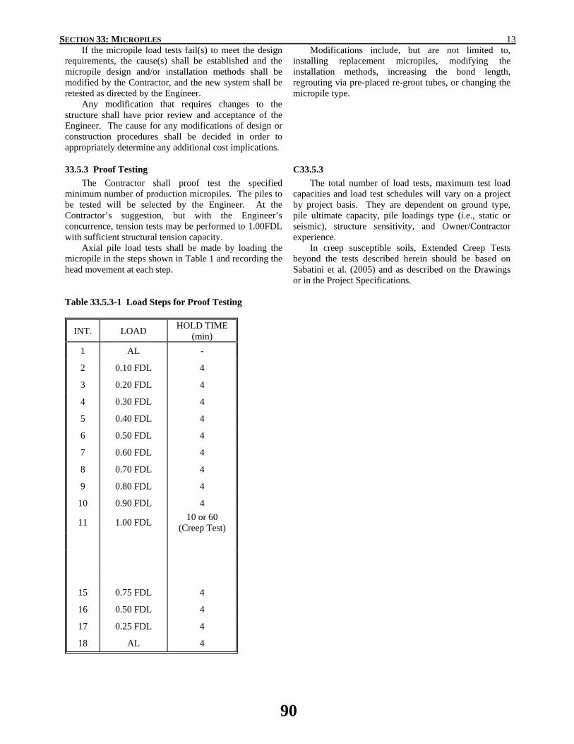
SECTION 33: MICROPILES 13 If the micropile load tests fail(s) to meet the design
requirements, the cause(s) shall be established and the micropile design and/or installation methods shall be modified by the Contractor, and the new system shall be retested as directed by the Engineer.
Any modification that requires changes to the structure shall have prior review and acceptance of the Engineer. The cause for any modifications of design or construction procedures shall be decided in order to appropriately determine any additional cost implications.
Modifications include, but are not limited to, installing replacement micropiles, modifying the installation methods, increasing the bond length, regrouting via pre-placed re-grout tubes, or changing the micropile type.
33.5.3 Proof Testing The Contractor shall proof test the specified
minimum number of production micropiles. The piles to be tested will be selected by the Engineer. At the Contractor’s suggestion, but with the Engineer’s concurrence, tension tests may be performed to 1.00FDL with sufficient structural tension capacity.
Axial pile load tests shall be made by loading the micropile in the steps shown in Table 1 and recording the head movement at each step.
C33.5.3 The total number of load tests, maximum test load
capacities and load test schedules will vary on a project by project basis. They are dependent on ground type, pile ultimate capacity, pile loadings type (i.e., static or seismic), structure sensitivity, and Owner/Contractor experience.
In creep susceptible soils, Extended Creep Tests beyond the tests described herein should be based on Sabatini et al. (2005) and as described on the Drawings or in the Project Specifications.
Table 33.5.3-1 Load Steps for Proof Testing
INT. LOAD HOLD TIME (min)
1 AL - 2 0.10 FDL 4 3 0.20 FDL 4 4 0.30 FDL 4 5 0.40 FDL 4 6 0.50 FDL 4 7 0.60 FDL 4 8 0.70 FDL 4 9 0.80 FDL 4
10 0.90 FDL 4
11 1.00 FDL 10 or 60 (Creep Test)
15 0.75 FDL 4 16 0.50 FDL 4 17 0.25 FDL 4 18 AL 4
90
SECTION 33: MICROPILES 14 The acceptance criteria for micropile proof load tests
shall be: 1. The pile shall sustain the compression and tension
design loads (0.75 FDL) with no more than the specified minimum permissible total vertical movement at the top of the pile as measured relative to the pile prior to the start of testing. If an Alignment Load is used, then the allowable movement will be reduced by multiplying by a factor of [(0.75 FDL-AL)/0.75 FDL].
2. Test piles shall have a creep rate at the end of the 1.00 FDL increment that is not greater than 0.04 in./log cycle time (1 to 10 minutes) or 0.08 in./log cycle time (6 to 60 minutes) and has a linear or decreasing creep rate.
3. Failure does not occur by 1.00 FDL test load.
If a production micropile fails to meet the acceptance criteria, modifications shall be made to the design, the construction procedures, or both.
Any modification that requires changes to the structure shall have prior review and acceptance of the Engineer. The cause for any modifications of design or construction procedures shall be decided in order to appropriately determine any additional cost implications.
Modifications include, but are not limited to, installing replacement micropiles, modifying the installation methods, increasing the bond length, regrouting via pre-placed re-grout tubes, or changing the micropile type. The Engineer may elect to proof test additional piles depending on the circumstances of the modifications.
33.5.4 Lateral Loading If required, lateral load testing shall be conducted in
accordance with the latest version of ASTM D3966. Lateral load testing shall be conducted before axial load testing. During both verification and proof test phases, care must be exercised to not cause permanent structural damage to the pile that will subsequently reduce its axial load capacity.
C33.5.4 The specified acceptance criterion, expressed as a
maximum total movement at a certain load, must be carefully selected so as not to potentially damage the structure.
33.6 MEASUREMENT AND PAYMENT
33.6.1 Method of Measurement
33.6.1.1 Mobilization and Demobilization Mobilization and demobilization will be measured
on a lump sum basis.
33.6.1.2 Micropiles Project specific criteria such as minimum pile
lengths and maximum top of bond zone elevation shall be as indicated in the Project Drawings or Project Specifications.
Micropiles, installed and accepted including test piles, will be measured per linear foot in soil and linear foot in rock. Micropiles, complete and in place, shall be of the types and shall provide the load resistances indicated in the contract documents or accepted in writing by the Engineer, and furnished in compliance with the material requirements of these specifications.
Such measurement shall not include micropiles damaged prior to completion of the work unless remedied to the satisfaction of the Engineer.
C33.6.1.2 This provision assumes the Owner has specified the
required micropile load resistances and quantity. Measurement may be stipulated as lump sum if micropile contractor determines the micropile quantity.
For projects with soil pile design by the Contractor, micropiles, including test piles, should be measured per each, installed and accepted.
For projects with rock pile design by the Contractor, micropiles, including test piles, should be measured per linear foot to rock, installed and accepted. Since the actual linear feet in rock may vary by Contractor the cost of the rock socket is not a separate item.
91

SECTION 33: MICROPILES 15
33.6.1.3 Verification Load Tests Verification load tests will be measured by the
number of load tests performed and accepted for each designated pile load capacity. Load tests made at the option of the Contractor shall not be included in the quantity measured for payment.
33.6.1.4 Proof Load Tests Proof load tests will be measured by the number of
load tests performed and accepted for each designated pile load capacity. Load tests made at the option of the Contractor shall not be included in the quantity measured for payment.
33.6.1.5 Obstruction Drilling Obstruction drilling will be measured by the hour
where obstructions, as defined in the contract documents, are encountered.
C33.6.1.5
An obstruction is generally defined as a specific object (including, but not limited to, boulders, logs, and man-made objects) encountered during the drilling operation that prevents or hinders the advance of the borehole.
33.6.2 Basis of Payment
33.6.2.1 Mobilization and Demobilization Mobilization and demobilization will be paid on a
lump sum basis in accordance with the contract documents. Such payment shall be considered full compensation for providing all labor, equipment, and materials needed to complete micropile installation and testing.
33.6.2.2 Micropiles Micropiles will be paid for at the contract price(s)
per linear foot in soil and per linear foot in rock for piles of the types specified and approved by the Engineer.
C33.6.2.2 Payment may be stipulated as lump sum if the
micropile contractor determines the micropile quantities. See also Article C33.6.1.2 for Contractor designed piles in soil.
The Contractor shall be responsible for estimating the grout take. There will be no extra payment for grout overruns, except as otherwise specified in the contract documents.
Payment for grout overrun may be appropriate on projects where such overrun is beyond the control of the Contractor such as voided ground (e.g., karst, urban fill, mines) as addressed in the contract documents.
33.6.2.3 Verification Load Tests Verification load tests will be paid for at the contract
price per test specified, satisfactorily completed, and meeting load carrying requirements.
Payment for verification load tests includes full compensation for providing all labor, equipment, and materials needed to perform load tests and submitting report(s) as specified.
33.6.2.4 Proof Load Tests Proof load tests will be paid for at the contract price
per test specified and satisfactorily completed and meeting load carrying requirements.
Payment for proof load tests includes full compensation for providing all labor, equipment, and materials needed to perform load tests and submitting report(s) as specified.
92
SECTION 33: MICROPILES 16
33.6.2.5 Obstruction Drilling Payment for obstruction drilling includes full
compensation for providing all labor and equipment needed to drill though or remove obstructions.
33.7 REFERENCES American Association of State Highway and Transportation Officials (AASHTO). 2006. Interim Standard Specifications for Transportation Materials and Methods of Sampling and Testing. Part I – Specifications, American Association of State Highway and Transportation Officials, Washington, D.C. American Petroleum Institute. (1998) Specification for Casing and Tubing API Specification 5CT, 6th Edition, API, Washington, DC. American Society for Testing and Materials (ASTM). 2006a. Volume 01.01, Steel--Piping, Tubing, Fittings, American Society for Testing and Materials, West Conshohocken, PA. American Society for Testing and Materials (ASTM). 2006b. Volume 01.04, Steel--Structural, Reinforcing, Pressure Vessel, Railway, American Society for Testing and Materials, West Conshohocken, PA. American Society for Testing and Materials (ASTM). 2006c. Volume 01.06, Coated Steel Products, American Society for Testing and Materials, West Conshohocken, PA. American Society for Testing and Materials (ASTM). 2007. Volume 04.08, Soil and Rock (I): D 420 - D 5876, American Society for Testing and Materials, West Conshohocken, PA. Post Tensioning Institute (2004). “Recommendations for Prestressed Rock and Soil Anchors”, 4th Edition, PTI, Phoenix, AZ, 70p. Sabatini, P.J., Tanyu, B., Armour, T., Groneck, P., and Keeley, J. (2005). "Micropile Design and Construction," FHWA NHI-05-039; NHI Course 132078 Reference Manual, December, 436 p.
93

2014 AASHTO BRIDGE COMMITTEE AGENDA ITEM: 20 SUBJECT: LRFD Bridge Design Specifications: Section 6, Articles 6.4.9 and 6.17 TECHNICAL COMMITTEE: T-14 Steel
REVISION ADDITION NEW DOCUMENT
DESIGN SPEC CONSTRUCTION SPEC MOVABLE SPEC MANUAL FOR BRIDGE SEISMIC GUIDE SPEC COASTAL GUIDE SPEC
EVALUATION OTHER DATE PREPARED: 7/22/13 DATE REVISED: AGENDA ITEM:Item #1 Add the following article to Section 6: 6.4.9−Dissimilar Metals Where steel components, including those made of stainless steel, are in contact with aluminum alloy components in the presence of an electrolyte, the aluminum shall be kept from direct contact with the steel. The steel components may include structural members, structural fasteners, washers and/or nuts. Item #2 Add the following article to Section 6: C6.4.9 Galvanic corrosion can occur when steel components, including those made of stainless steel, are coupled with aluminum in the presence of an electrolyte. The aluminum part acts as an anode and will be sacrificed in time. This galvanic corrosion can be prevented by isolating the two materials from each other. Materials such as dielectric elastomeric spacers have also been used to keep aluminum alloy parts from direct contact with steel or other dissimilar metals. Additional information can be found in AASHTO (2013) under the Aluminum Design Section. Item #3 Insert the following in the Section 6 reference list in Article 6.17: AASHTO. 2013. Standard Specifications for Structural Supports for Highway Signs, Luminaires, and Traffic Signals, Sixth Edition, American Association of State Highway and Transportation Officials, Washington, DC.
OTHER AFFECTED ARTICLES:None
94

BACKGROUNDThe proposed revision will insert into the AASHTO LRFD Bridge Design Specification language from Section 6.11-Protection of the Sixth Edition, 2013, Standard Specifications for Structural Supports for Highway Signs, Luminaires, and Traffic Signals regarding the corrosion phenomenon due to the contact of steel and aluminum in environments with electrolyte/chlorides. The proposed change is a result of two failures (March 2011 and September 2012) of lighting fixtures within highway tunnels. FHWA Office of Bridge Technology issued the following memorandum for the Inspection of Overhead Connections in Tunnels in November, 2012:
Memorandum
Subject: ACTION: Inspection of Overhead Connections in Tunnels
/s/ Original Signed by Date: November 5, 2012
From: John Baxter In Reply Refer To: Associate Administrator for Infrastructure HIBT-1
To: Directors of Field Services Federal Lands Highway Division Engineers Division Administrators
On September 30, 2012, an overhead luminaire (lighting fixture) fell from its support bracket onto a parking apron within the portal of the downtown side of Ft. Pitt Tunnel in Pittsburgh, PA. The connection failed as a result of galvanic corrosion between the aluminum frame of the luminaire and the stainless steel bolts connecting it to the support bracket.
Galvanic corrosion is an electrochemical process that can occur between dissimilar metals. During this process, metallic ions sacrificially move from the less noble metal (smaller atomic number) to the more noble metal which accelerates the deterioration of the less noble metal while retarding the deterioration of the more noble metal.
The incident and PennDOT’s response are described more thoroughly in the attached report developed by the Office of Bridge Technology and the PA Division Office. The incident is also very similar to one that occurred in Boston’s Central Artery/Tunnel (CA/T) in March of 2011. The results of that investigation were circulated by the Office of Bridge Technology and are also attached for your reference.
Although both recent incidents could have resulted in tragic consequences, fortunately, no one was injured. However, both of these incidents could have been prevented by routinely inspecting the connections and elements of the luminaires. Inadequate inspection also contributed to the collapse of the suspended ceiling in the CA/T in 2006 which tragically resulted in a fatality. That incident was one of the primary motivators for the development of National Tunnel Inspection Standards (NTIS) which are currently in the rule making process.
Please visit with your State transportation agency partner to assure that they are aware of these recent issues and their cause. Also, during that visit, strongly recommend that they both identify potentially similar issues in their inventory and begin inspecting those connections and elements adequately to assure safety.
95

Please meet with your State transportation agency partner and report back any relevant outcomes of that meeting by December 14, 2012, to Mr. Myint Lwin at (202)366-4589 or [email protected] or Mr. Joseph Hartmann at (202) 366-4599 or [email protected].
Attachment: Event Report: Ft. Pitt Tunnel Luminaire Connect Failure
BACKGROUND (cont):The American Institute of Steel Construction, Steel Construction Manual, General Features for Design Considerations has a chart “Metal Fastener Compatibility to Resist Corrosion”. The chart indicates that the corrosion of aluminum and aluminum alloy connected with Austenitic Stainless Steel (Type 302/304, 303 and 305 is marginally increased by the fastener, while connections with Martensitic Stainless Steel (Type 410) are not recommended. It is assumed that these charts do not account for the environment that highway structures are exposed to and thus are not appropriate.
ANTICIPATED EFFECT ON BRIDGES:A reduced possibility of galvanic corrosion failures when dissimilar metals, namely steel and aluminum, are connected together in the presence of an electrolyte.
REFERENCES: None
OTHER: None
96
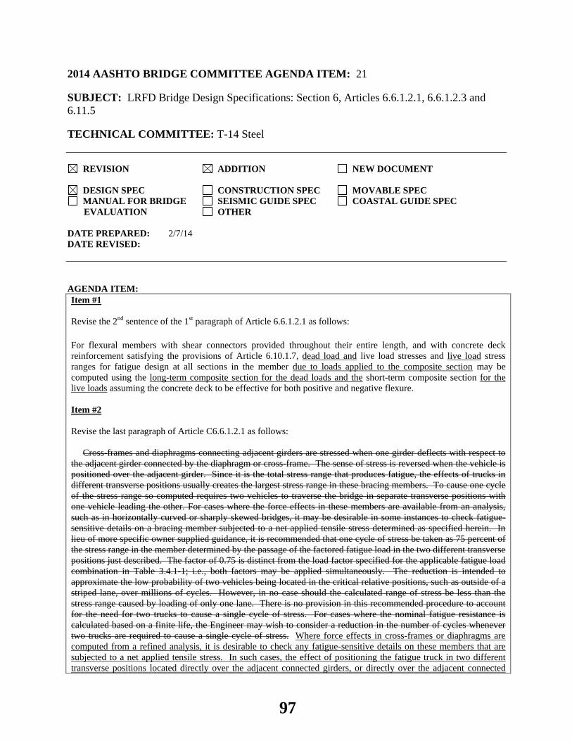
2014 AASHTO BRIDGE COMMITTEE AGENDA ITEM: 21 SUBJECT: LRFD Bridge Design Specifications: Section 6, Articles 6.6.1.2.1, 6.6.1.2.3 and 6.11.5 TECHNICAL COMMITTEE: T-14 Steel
REVISION ADDITION NEW DOCUMENT
DESIGN SPEC CONSTRUCTION SPEC MOVABLE SPEC MANUAL FOR BRIDGE SEISMIC GUIDE SPEC COASTAL GUIDE SPEC
EVALUATION OTHER DATE PREPARED: 2/7/14 DATE REVISED: AGENDA ITEM:Item #1 Revise the 2nd sentence of the 1st paragraph of Article 6.6.1.2.1 as follows: For flexural members with shear connectors provided throughout their entire length, and with concrete deck reinforcement satisfying the provisions of Article 6.10.1.7, dead load and live load stresses and live load stress ranges for fatigue design at all sections in the member due to loads applied to the composite section may be computed using the long-term composite section for the dead loads and the short-term composite section for the live loads assuming the concrete deck to be effective for both positive and negative flexure. Item #2 Revise the last paragraph of Article C6.6.1.2.1 as follows: Cross-frames and diaphragms connecting adjacent girders are stressed when one girder deflects with respect to the adjacent girder connected by the diaphragm or cross-frame. The sense of stress is reversed when the vehicle is positioned over the adjacent girder. Since it is the total stress range that produces fatigue, the effects of trucks in different transverse positions usually creates the largest stress range in these bracing members. To cause one cycle of the stress range so computed requires two vehicles to traverse the bridge in separate transverse positions with one vehicle leading the other. For cases where the force effects in these members are available from an analysis, such as in horizontally curved or sharply skewed bridges, it may be desirable in some instances to check fatigue-sensitive details on a bracing member subjected to a net applied tensile stress determined as specified herein. In lieu of more specific owner supplied guidance, it is recommended that one cycle of stress be taken as 75 percent of the stress range in the member determined by the passage of the factored fatigue load in the two different transverse positions just described. The factor of 0.75 is distinct from the load factor specified for the applicable fatigue load combination in Table 3.4.1-1; i.e., both factors may be applied simultaneously. The reduction is intended to approximate the low probability of two vehicles being located in the critical relative positions, such as outside of a striped lane, over millions of cycles. However, in no case should the calculated range of stress be less than the stress range caused by loading of only one lane. There is no provision in this recommended procedure to account for the need for two trucks to cause a single cycle of stress. For cases where the nominal fatigue resistance is calculated based on a finite life, the Engineer may wish to consider a reduction in the number of cycles whenever two trucks are required to cause a single cycle of stress. Where force effects in cross-frames or diaphragms are computed from a refined analysis, it is desirable to check any fatigue-sensitive details on these members that are subjected to a net applied tensile stress. In such cases, the effect of positioning the fatigue truck in two different transverse positions located directly over the adjacent connected girders, or directly over the adjacent connected
97
girder webs in the case of a box section, usually creates the largest range of stress or torque in these bracing members. There is an extremely low probability of the truck being located in these two critical relative transverse positions over millions of cycles. Field observation has also generally not indicated a significant problem with the details on these members caused by load-induced fatigue or fatigue due to cross-section distortion. Therefore, in order to compute more representative ranges of stress or torque for checking fatigue in these members whenever refined analysis methods are employed, it is recommended that the fatigue truck be positioned to determine the maximum range of stress or torque, as applicable, in these members as specified in Article 3.6.1.4.3a, with the truck confined to one critical transverse position per each longitudinal position throughout the length of the bridge in the analysis. Item #3 Revise the Description for Condition 4.1 in Table 6.6.1.2.3-1 as follows: 4.1 Base metal at the toe of transverse stiffener-to-flange fillet welds and transverse stiffener-to-web fillet welds (Note: includes similar welds on bearing stiffeners and connection plates). Base metal adjacent to bearing stiffener-to-flange groove welds. Item #4 Revise the paragraph immediately under the bullet list in Article 6.11.5 as follows: The stress range due to longitudinal warping shall be considered in checking the fatigue resistance of the base metal at all details on the box section according to the provisions specified in Article 6.6.1. The transverse bending stress range shall be considered separately in evaluating the fatigue resistance of the base metal adjacent to flange-to-web fillet welds and adjacent to the termination of fillet welds connecting transverse elements to webs and box flanges. In determining the longitudinal warping and transverse bending stress ranges, one cycle of stress shall be defined as 75 percent of the stress range determined by the passage of the factored fatigue load in two different critical transverse positions. In no case shall the stress range calculated in this manner be less than the calculated stress range due to the passage of the factored fatigue load in only one lane. The need for a bottom transverse member within the internal cross-frames to resist the transverse bending stress range in the bottom box flange at the termination of fillet welds connecting cross-frame connection plates to the flange shall be investigated. Transverse cross-frame members next to box flanges shall be attached to the box flange unless longitudinal flange stiffeners are used, in which case the transverse members shall be attached to the longitudinal stiffeners by bolting. The moment of inertia of these transverse cross-frame members shall not be less than the moment of inertia of the largest connection plate for the internal cross-frame member under consideration taken about the edge in contact with the web. Item #5 Add the following to the beginning of the 2nd paragraph in Article C6.11.5: Where force effects in the cross-frames or diaphragms are computed from a refined analysis, stress ranges for checking load-induced fatigue and torque ranges for checking fatigue due to cross-section distortion in cross-frame and diaphragm members should be determined as recommended in Article C6.6.1.2.1. Transverse bending and longitudinal warping stress ranges due to cross-section distortion can be determined using the BEF analogy, as discussed in Article C6.11.1.1. Longitudinal warping stresses are considered additive to the longitudinal major-axis bending stresses. Delete the 3rd paragraph of Article C6.11.5.
OTHER AFFECTED ARTICLES:None
98
BACKGROUNDSeveral revisions are proposed to this article that are summarized as follows: Item #1: Revisions are proposed in the 1st paragraph of Article 6.6.1.2.1 to indicate that when the specified conditions are met, all dead load and live load stresses and live load stress ranges for fatigue design due to loads applied to the appropriate corresponding composite section may be computed assuming the concrete deck to be effective for positive and negative flexure. This includes stresses due to the dead loads, DC2 and DW, which are typically applied to the long-term 3n composite section, and live load stresses, which are typically applied to the short-term n composite section. These dead and live load stresses are used to determine whether or not a detail is subject to a net tensile stress indicating that fatigue of that detail must be checked, in which case the live load stress ranges must then be computed. Items #2 and #4: Revisions are proposed in Item #2 to clarify the calculation of the stress or torque range in cross-frame/diaphragm members in cases where the force effects in these members are computed from a refined analysis and are available to check fatigue-sensitive details on these members subject to a net tensile stress. The current language in Article C6.6.1.2.1 and Article 6.11.5 permits one cycle of stress or torque in these members to be taken as 75 percent of the stress or torque range in the member determined by the passage of the fatigue truck in two different transverse positions directly over the adjacent connected girders, or directly over the adjacent connected girder webs in the case of a box girder. The effect of the fatigue truck located in these critical relative transverse positions usually creates the largest stress or torque range in these members. The reduced range is not to be taken less than the range caused by the passage of the load in a single lane. However, there is an extremely low probability of two vehicles being located in these critical relative transverse positions over millions of cycles. Field observation has also generally not indicated a significant problem with the details on these members caused by load-induced fatigue or fatigue due to cross-section distortion. Therefore, in order to compute more representative ranges of stress or torque for checking fatigue in these members, revisions to the language in Article C6.6.1.2.1 are proposed in Item #2 to recommend that the maximum range of stress or torque be computed by confining the fatigue truck to one critical transverse position per each longitudinal position throughout the length of the bridge in the analysis. Revisions are also proposed to Articles 6.11.5 and C6.11.5 in Item #4 to essentially refer back to this recommendation given in Article C6.6.1.2.1 when calculating the stress range for checking load-induced fatigue, and the torque range for checking fatigue due to cross-section distortion, in cross-frame and diaphragm members in box girders. Item #3: A revision is proposed to the Description for Condition 4.1 in Table 6.6.1.2.3-1 to add the case where groove welds may be used to connect a bearing stiffener to a flange. Although not a recommended detail, where used, the fatigue category for this detail is to be taken as Category C′.
ANTICIPATED EFFECT ON BRIDGES:Clarification of several items related to the checking of fatigue details in steel bridges and the computation of stress and torque ranges in cross-frame or diaphragm members. The proposed revisions should lead to the computation of more representative stress and torque ranges, as applicable, for the checking of fatigue-sensitive details on these members that are subject to a net applied tensile stress when the force effects in these members are computed from a refined analysis.
REFERENCES: None
OTHER: None
99

2014 AASHTO BRIDGE COMMITTEE AGENDA ITEM: 22 SUBJECT: LRFD Bridge Design Specifications: Section 6, Article 6.6.2 TECHNICAL COMMITTEE: T-14 Steel
REVISION ADDITION NEW DOCUMENT
DESIGN SPEC CONSTRUCTION SPEC MOVABLE SPEC MANUAL FOR BRIDGE SEISMIC GUIDE SPEC COASTAL GUIDE SPEC
EVALUATION OTHER DATE PREPARED: 2/5/14 DATE REVISED: AGENDA ITEM:Item #1 Revise the 4th paragraph of Article 6.6.2 as follows: Charpy V-notch impact energy requirements shall be in accordance with Table 6.6.2-2 AASHTO M 270M/M 270 (ASTM A709/A709M) for the appropriate specified temperature zone. The yield strength shall be taken as the value given in the certified Mill Test Report. Item #2 Revise the last paragraph of Article 6.6.2 as follows: Any attachment, except for bearing sole plates, having a length in the direction of the tension stress greater than 4.0 in. that is welded to a tension area of a component of a FCM shall be considered part of the tension component and shall be considered fracture-critical. Item #3 Revise the 3rd paragraph of Article C6.6.2 as follows: The Charpy V-notch impact energy requirements, specified in AASHTO M 270M/M 270 (ASTM A709/A709M) and shown in Table C6.6.2-1, are the same regardless of whether the component is welded or mechanically fastened, but vary depending on the type grade of steel, type of construction, and the applicable minimum service temperature. FCMs are subject to more stringent Charpy V-notch impact energy requirements than nonfracture-critical components. Change Table 6.6.2-2 to Table C6.6.2-1.
OTHER AFFECTED ARTICLES:None
100

BACKGROUND:Revisions proposed to this article are summarized as follows: Items #1 and #3: A revision is proposed in Item #1 to ensure that the contract documents reference the AASHTO M 270M/M 270 (ASTM A709/A709M) specification, rather than Table 6.6.2-2, to ensure that the latest Charpy V-notch requirements are used. It is further proposed in Item #3 that Table 6.6.2-2 be moved to the commentary and retained for information purposes. Item #2: A revision is proposed to exempt bearing sole plates from FCM requirements. Bearing sole plates welded to tension flanges are typically located in regions of low (to zero) tensile stress. Furthermore, these components are likely to be field welded, and an unnecessary fracture-critical designation of those welds can result in complications in the field welding. For example, in the cases of an elastomeric bearing pad vulcanized to a plate, or a field repair to the area near an already installed bearing, the required minimum fracture-critical preheat for the weld may exceed the maximum allowable temperature for the bearing material. A similar revision was recently made in the AREMA Specification.
ANTICIPATED EFFECT ON BRIDGES:None
REFERENCES: None
OTHER: None
101

2014 AASHTO BRIDGE COMMITTEE AGENDA ITEM: 23 SUBJECT: LRFD Bridge Design Specifications: Section 6, Article 6.10.3.4, TECHNICAL COMMITTEE: T-14 Steel
REVISION ADDITION NEW DOCUMENT
DESIGN SPEC CONSTRUCTION SPEC MOVABLE SPEC MANUAL FOR BRIDGE SEISMIC GUIDE SPEC COASTAL GUIDE SPEC
EVALUATION OTHER DATE PREPARED: 3/31/14 DATE REVISED: AGENDA ITEMItem # 1
Add the following at the beginning of Article 6.10.3.4:
6.10.3.4.1−General
Change ′C6.10.3.4′ to ′C6.10.3.4.1′.
Change Eqs. C6.10.3.4-1, C6.10.3.4-2 and C6.10.3.4-3 to Eqs. C6.10.3.4.1-1, C6.10.3.4.1-2 and C6.10.3.4.1-3.
In the 2nd paragraph of Article C6.10.3.4 (renamed to Article C6.10.3.4.1), change Eq. C6.10.3.4-1 to Eq. C6.10.3.4.1-1 (at two locations).
In the paragraph underneath Eq. C6.10.3.4-3 (renamed to Eq. C6.10.3.4.1-3), change Eq. C6.10.3.4-2 and Eq. C6.10.3.4-3 to Eq. C6.10.3.4.1-2 and Eq. C6.10.3.4.1-3.
Add the following at the end of Article 6.10.3.4:
6.10.3.4.2—Global Displacement Amplification in Slender I-Girder Bridge Units
The provisions of this article shall apply to spans of I-girder bridge units with three or fewer girders, interconnected by cross-frames or diaphragms, that also meet both of the following conditions in their noncomposite condition during the deck placement operation:
• The unit is not braced by other structural units and/or by external bracing within the span; and
• The unit does not contain any flange level lateral bracing or lateral bracing from a hardened composite deck within the span.
Considering all of the girders across the width of the unit within the span under consideration, the sum of the largest total factored positive girder moments during the deck placement should not exceed 50 percent of the elastic global lateral-torsional buckling resistance of the span acting as a system. The elastic global lateral-torsional buckling resistance of the span acting as a system, Mgs, may be calculated as follows:
2
2gs eff xsEM I I
Lπ
= (6.10.3.4.2-1)
in which:
• For doubly symmetric girders:
102

yeff II = (6.10.3.4.2-2)
• For singly symmetric girders:
ytyceff IctII
+= (6.10.3.4.2-3)
where:
c = distance from the centroid of the noncomposite steel section under consideration to the centroid of the compression flange (in.). The distance shall be taken as positive.
Ix = noncomposite moment of inertia about the horizontal centroidal axis of a single girder within the span under consideration (in.4)
Iyc, Iyt = moments of inertia of the compression and tension flange, respectively, about the vertical centroidal axis of a single girder within the span under consideration (in.4)
Iy = noncomposite moment of inertia about the vertical centroidal axis of a single girder within the span under consideration (in.4)
L = length of the span under consideration (in.)
s = for a two-girder system, the girder spacing (in.); for a three-girder system, the distance between the two exterior girders of the unit (in.)
t = distance from the centroid of the noncomposite steel section under consideration to the centroid of the tension flange (in.). The distance shall be taken as positive.
Should the sum of the largest total factored positive girder moments across the width of the unit within the span under consideration exceed 50 percent of Mgs, the following alternatives may be considered:
• The addition of flange level lateral bracing adjacent to the supports of the span may be considered as discussed in Article 6.7.5.2;
• The unit may be revised to increase the system stiffness; or
• The amplified girder second-order displacements of the span during the deck placement may be evaluated to verify that they are within tolerances permitted by the Owner.
Item # 2
Add the following to the end of the current Article C6.10.3.4: C6.10.3.4.2 The recommendations in this article are intended to avoid excessive amplification of the lateral and vertical displacements of slender I-girder bridge units during the deck placement operation before the concrete deck has hardened. The elastic global buckling resistance may be used as an indicator of the susceptibility of general straight, curved and/or skewed I-girder systems to 2nd-order amplification under noncomposite loading conditions (White et al., 2012). The global buckling mode in this case refers to buckling of the bridge unit as a structural unit, and not buckling of the girders between intermediate braces. Limiting the sum of the total factored positive girder moments across the width of the unit within the span under consideration to 50 percent of the elastic global buckling resistance of the span acting as a system theoretically limits the amplification under the corresponding nominal loads to a maximum value of approximately 1.5. Eq. 6.10.3.4.2-1 (Yura et al., 2008) provides one method of estimating the elastic global lateral-torsional buckling resistance of a given I-girder bridge span under noncomposite loading conditions. Two-girder units are particularly susceptible to excessive global lateral-torsional amplification during the deck placement; however, units with large span/width ratios having up to three girders also may be susceptible to significant global amplification in some cases. Other methods, such as an eigenvalue buckling analysis or a global 2nd-order load-deflection analysis, may also be used to determine the response of the system. Once a concrete deck is acting compositely with the steel girders, a given span of a bridge unit is practically always stable as an overall system;
103
Eq. 6.10.3.4.2-1 is not intended for application to I-girder bridge spans in their composite condition. Eq. 6.10.3.4.2-1 is also not applicable to I-girder bridge units with more than three girders, which are typically not susceptible to excessive global lateral-torsional amplification during the deck placement.
Eq. 6.10.3.4.2-1 was derived assuming prismatic girders and that all girder cross-sections in the unit are the same. For cases where the girders are nonprismatic and/or the girder cross-sections vary across the unit, it is recommended herein that length-weighted average moments of inertia within the positive-moment sections of all the girders in the span under consideration be used for Ix, Iy, Iyc and Iyt, as applicable, in calculating the elastic global lateral-torsional buckling resistance from Eq. 6.10.3.4.2-1. Also, in cases where the girder spacing is less than the girder depth, it is recommended that the more general elastic global lateral-torsional buckling equation provided in Yura et. al. (2008) be used, as Eq. 6.10.3.4.2-1 becomes more conservative in this case. Yura et al. (2008) further indicates the adjustments that need to be made to the more general buckling equation for singly symmetric girders and/or for three-girder systems.
Large global torsional rotations signified by large differential vertical deflections between the girders and also large lateral deflections, as determined from a first-order analysis, are indicative of the potential for significant second-order global amplification. Situations exhibiting potentially significant global second-order amplification include phased construction involving narrow unsupported units with only two or three girders and possibly unevenly applied deck weight. One suggested method of increasing the global buckling resistance in such cases is to consider the addition of flange level lateral bracing to the system. Yura et al. (2008) suggest adjustments to be made when estimating the elastic global lateral-torsional buckling resistance of the system where a partial top-flange lateral bracing system is present at the ends of the span, along with some associated bracing design recommendations. Item #3
Add the following definition to Article 6.2:
Global Lateral-Torsional Buckling – Buckling mode in which a system of girders buckle as a unit with an unbraced length equal to the clear span of the girders.
Add the following references to the Section 6 reference list:
Yura, J.A., Helwig, T., Herman, R., and Zhou, C. 2008. “Global Lateral Buckling of I-Shaped Girder Systems,” Journal of Structural Engineering, ASCE, 134(9), 1487-1494. Item #4
Modify the Notation list in Article 6.3 as follows:
c = distance from the centroid of the noncomposite steel section under consideration to the centroid of the compression flange (in.); distance from the center of the longitudinal reinforcement to the nearest face of a concrete-encased shape in the plane of bending (in.) (6.10.3.4.2) (6.12.2.3.1)
Ieff = effective noncomposite moment of inertia about the vertical centroidal axis of a single girder within the span under consideration used in calculating the elastic global lateral-torsional buckling resistance of the span (in.4) (6.10.3.4.2)
Ix = moments of inertia about the major principal axis of the cross-section (in.4); noncomposite moment of inertia about the horizontal centroidal axis of a single girder within the span under consideration (in.4) (6.9.4.1.3) (6.10.3.4.2)
Iy = moments of inertia about the minor principal axis of the cross-section (in.4); noncomposite moment of inertia about the vertical centroidal axis of a single girder within the span under consideration (in.4); moments of inertia of a box-shape member about an axis perpendicular to the axis of bending (in.4); moments of inertia about the minor principal axis of the cross-section (in.4); moment of inertia about the y-axis (in.)4 (6.9.4.1.3) (6.10.3.4.2) (6.12.2.2.2) (6.12.2.2.4) (6.12.2.2.5)
Iyc = moment of inertia of the compression flange of a steel section about the vertical axis in the plane of the web (in.4); moment of inertia of the compression flange about the vertical centroidal axis of a single girder within the span under consideration (in.4) (6.10.2.2) (6.10.3.4.2)
Iyt = moment of inertia of the tension flange of a steel section about the vertical axis in the plane of the web (in.4); moment of inertia of the tension flange about the vertical centroidal axis of a single girder within the span under consideration (in.4) (6.10.2.2) (6.10.3.4.2)
104

L = effective span length for determining additional camber to compensate for possible loss of camber in a heat-curved girder (in.); maximum length of the connection longitudinal welds or the out-to-out distance between the bolts in the connection parallel to the line of force (in.); length of a girder shipping piece (in.); length of the span under consideration (in.); distance from a single bolt to the free edge of the member measured parallel to the line of applied force (in.) (6.6.1.2.3) (6.7.7.3) (6.8.2.2) (C6.10.3.4.1) (6.10.3.4.2) (C6.13.2.9)
Mgs = elastic global lateral-torsional buckling resistance of a span (kip-in.) (6.10.3.4.2) s = pitch of any two consecutive bolts in a staggered chain (in.); girder spacing for a two-girder system or
the distance between the two exterior girders of the unit for a three-girder system (in.); longitudinal spacing of transverse reinforcement in a concrete-encased shape (in.); spacing of bolts on a single line or in a staggered pattern adjacent to a free edge of an outside plate or shape (in.); vertical pitch of bolts in a web splice (in.) (6.8.3) (6.10.3.4.2) (6.12.3.1) (6.13.2.6.2) (C6.13.6.1.4b)
t = thickness of plate or plates (in.); thickness of tube or wall (in.); distance from the centroid of the noncomposite steel section under consideration to the centroid of the tension flange (in.); thickness of the thinner outside plate or shape (in.); thickness of the connected material (in.); thickness of the thinnest connected part (in.); thickness of tube (in.); width of the rectangular bar parallel to the axis of bending (in.) (C6.7.4.3) (6.9.4.2.1) (6.10.3.4.2) (6.12.1.2.3c) (6.12.2.2.3) (6.12.2.2.7) (6.13.2.6.2) (6.13.2.9) (6.13.2.10.4)
OTHER AFFECTED ARTICLES:In the Notation list in Article 6.3, change C6.10.3.4 to C6.10.3.4.1 in the definitions for Fℓ, L, Mℓ and Pℓ. In the 2nd paragraph of Article C6.7.4.2, change C6.10.3.4 to C6.10.3.4.1. In the 4th paragraph of Article C6.10.1.6, change Article C6.10.3.4 to Article C6.10.3.4.1. In the 2nd and 5th paragraphs of Article C6.10.2.2, change Eq. C6.10.3.4-1 to Eq. C6.10.3.4.1-1. In the 5th paragraph of Article C6.11.3.2, change Eq. C6.10.3.4-2 to Eq. C6.10.3.4.1-2 and Eq. C6.10.3.4-3 to Eq. C6.10.3.4.1-3. In the 6th paragraph of Article C6.11.3.2, change Eq. C6.10.3.4-2 to C6.10.3.4.1-2. In the 8th paragraph of Article C6.11.3.2, change Eq. 6.10.3.4-1 to Eq. 6.10.3.4.1-1 (at three locations).
BACKGROUND:The specification and commentary language proposed for inclusion in Articles 6.10.3.4 and C6.10.3.4 supplements the requirements of Article 2.5.3, which are referenced by Article 6.10.3.1, by providing specific guidelines for checking the global stability of spans of certain slender unsupported straight or horizontally curved multiple I-girder bridge units interconnected by cross-frames or diaphragms when in their noncomposite condition during the deck placement operation. In certain situations, spans of slender unsupported straight or horizontally curved steel I-girder bridge units can be vulnerable to overall (i.e., global) elastic stability related failures during their construction. The noncomposite dead loads must be resisted predominantly by the steel structure during deck placement prior to hardening of the concrete deck. Relatively slender I-girder bridge units (i.e., units with large span-to-width ratios and with three or fewer girders) may be susceptible to global stability problems rather than cross-section or individual unbraced length strength limit states during the deck placement (Yura et al., 2008). Due to second-order lateral-torsional amplification of the displacements and stresses, the limit of the structural resistance may be reached well before the theoretical elastic buckling resistance. Large displacement amplifications can make it difficult to predict and control the structure geometry. The proposed additions to Articles 6.10.3.4 and C6.10.3.4 provide one means of estimating the global lateral-torsional buckling resistance of slender unsupported multiple I-girder units with three or fewer girders interconnected by cross-frames or diaphragms when in their noncomposite condition during the deck placement operation.
ANTICIPATED EFFECT ON BRIDGESThe proposed changes to Articles 6.10.3.4 and C6.10.3.4 alert the Engineer to potential situations where global second-order amplification of the girder vertical and lateral displacements may lead to construction difficulties during the deck placement operation, and provide requirements to avoid these situations.
105

REFERENCES: See Item #3
OTHER: None
106
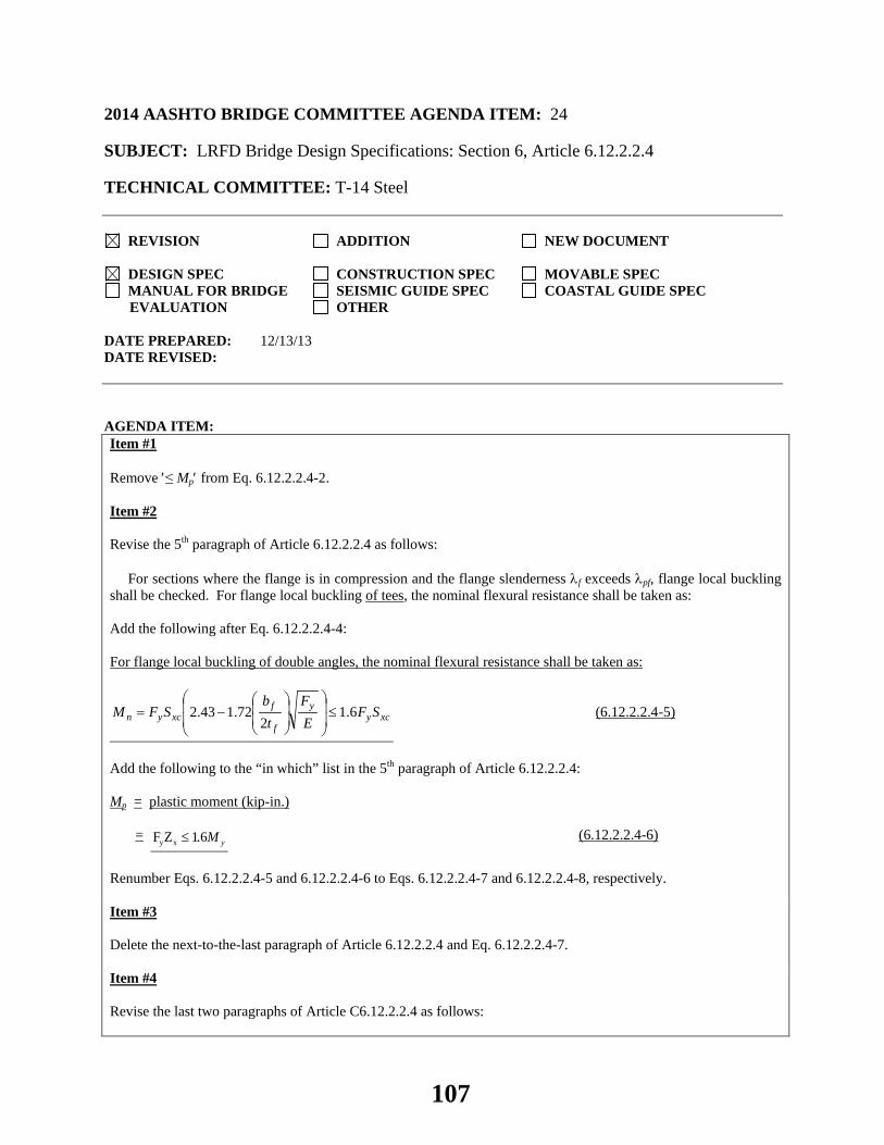
2014 AASHTO BRIDGE COMMITTEE AGENDA ITEM: 24 SUBJECT: LRFD Bridge Design Specifications: Section 6, Article 6.12.2.2.4 TECHNICAL COMMITTEE: T-14 Steel
REVISION ADDITION NEW DOCUMENT
DESIGN SPEC CONSTRUCTION SPEC MOVABLE SPEC MANUAL FOR BRIDGE SEISMIC GUIDE SPEC COASTAL GUIDE SPEC
EVALUATION OTHER DATE PREPARED: 12/13/13 DATE REVISED: AGENDA ITEM:Item #1 Remove ′≤ Mp′ from Eq. 6.12.2.2.4-2. Item #2 Revise the 5th paragraph of Article 6.12.2.2.4 as follows: For sections where the flange is in compression and the flange slenderness λf exceeds λpf, flange local buckling shall be checked. For flange local buckling of tees, the nominal flexural resistance shall be taken as: Add the following after Eq. 6.12.2.2.4-4: For flange local buckling of double angles, the nominal flexural resistance shall be taken as:
xcyy
f
fxcyn SF
EF
tb
SFM 6.12
72.143.2 ≤
−= (6.12.2.2.4-5)
Add the following to the “in which” list in the 5th paragraph of Article 6.12.2.2.4: Mp = plastic moment (kip-in.) =
y xF Z 1.6 yM≤ (6.12.2.2.4-6)
Renumber Eqs. 6.12.2.2.4-5 and 6.12.2.2.4-6 to Eqs. 6.12.2.2.4-7 and 6.12.2.2.4-8, respectively. Item #3 Delete the next-to-the-last paragraph of Article 6.12.2.2.4 and Eq. 6.12.2.2.4-7. Item #4 Revise the last two paragraphs of Article C6.12.2.2.4 as follows:
107

For cases where the flange is in compression and λf does not exceed λpf, flange local buckling does not control and need not be checked. Eq. 6.12.2.2.4-4 represents an inelastic flange local buckling resistance equation and corrects an error in the inelastic flange local buckling equation provided for tees in AISC (2010). Eq. 6.12.2.2.4-5 represents a local buckling resistance equation provided for determining the inelastic local buckling resistance of single-angle legs in Section F10 of AISC (2010), which is conservatively applied to determine the inelastic local buckling resistance of the compression flange of double angles loaded in the plane of symmetry as recommended in AISC (2010). An eElastic flange local buckling resistance equations for cases with λf exceeding λrf, i.e. for slender flanges, isare not provided because the limiting slenderness value λrf beyond which elastic flange local buckling controls is larger than the limiting slenderness value of 12.0 given by Eq. 6.10.2.2-1. The flanges of all rolled tee sections given in AISC (2010) satisfy Eq. 6.10.2.2-1; therefore, this limit need only be checked for fabricated sections. An elastic flange local buckling resistance equation is provided in AISC (2010). Eq. 6.12.2.2.4-7 for checking local buckling of stems in compression is indirectly derived from Eq. 6.12.2.2.4-2 in the limit of zero unbraced length. Separate equations for checking local buckling of stems in compression are not provided herein. Lateral torsional buckling and local buckling of the stem are essentially the same phenomenon for these sections. Hence, satisfaction of Eq. 6.12.2.2.4-2 will ensure that local buckling of the stem in compression will not occur.
OTHER AFFECTED ARTICLES:None
BACKGROUND:Several revisions are proposed to this article that are summarized as follows: Item #1: The upper limit of Mp is removed from the lateral torsional buckling resistance equation to avoid any potential confusion related to whether or not the upper limit of 1.6My applies for the case where the stem is in tension. The upper limit of Mp ≤ 1.6My for this case will not be exceeded regardless should yielding control the nominal flexural resistance. Item #2: In the 2010 AISC Specification, the current Eq. 6.12.2.2.4-4 applies when determining the flange inelastic local buckling resistance for tees. The 2010 AISC Specification recommends that the local buckling resistance equation provided for determining the inelastic local buckling resistance of single-angle legs be conservatively applied to calculate the inelastic local buckling resistance of the compression flange of double angles loaded in the plane of symmetry. The proposed new Eq. 6.12.2.2.5-5 reflects this recommendation. Also, a definition for Mp has been added to ensure that when Eq. 6.12.2.2.4-4 is applied for determining the flange inelastic local buckling resistance for tees (i.e. for the case where the stem is in tension), the upper limit of 1.6My will not be exceeded in order to control yielding of the stem at service load levels. Item #3: The local buckling check for the stem in compression is removed because the check is considered redundant. Lateral torsional buckling and local buckling of the stem are essentially the same phenomenon for these sections. Therefore, satisfaction of Eq. 6.12.2.2.4-2 will ensure that local buckling of the stem in compression will not occur. Item #4: Revisions to the commentary language in Article C6.12.2.2.4 are proposed to be consistent with the revisions proposed herein.
ANTICIPATED EFFECT ON BRIDGES:Clarification of the calculation of the plastic moment capacity, Mp, in the determination of the lateral torsional buckling resistance and flange local buckling resistance of tees. More accurate calculation of the compression flange local buckling resistance of double angles.
108

REFERENCES: AISC. 2010. Specification for Structural Steel Buildings, ANSI/AISC 360-10. American Institute of Steel Construction, Chicago, IL.
OTHER: None
109
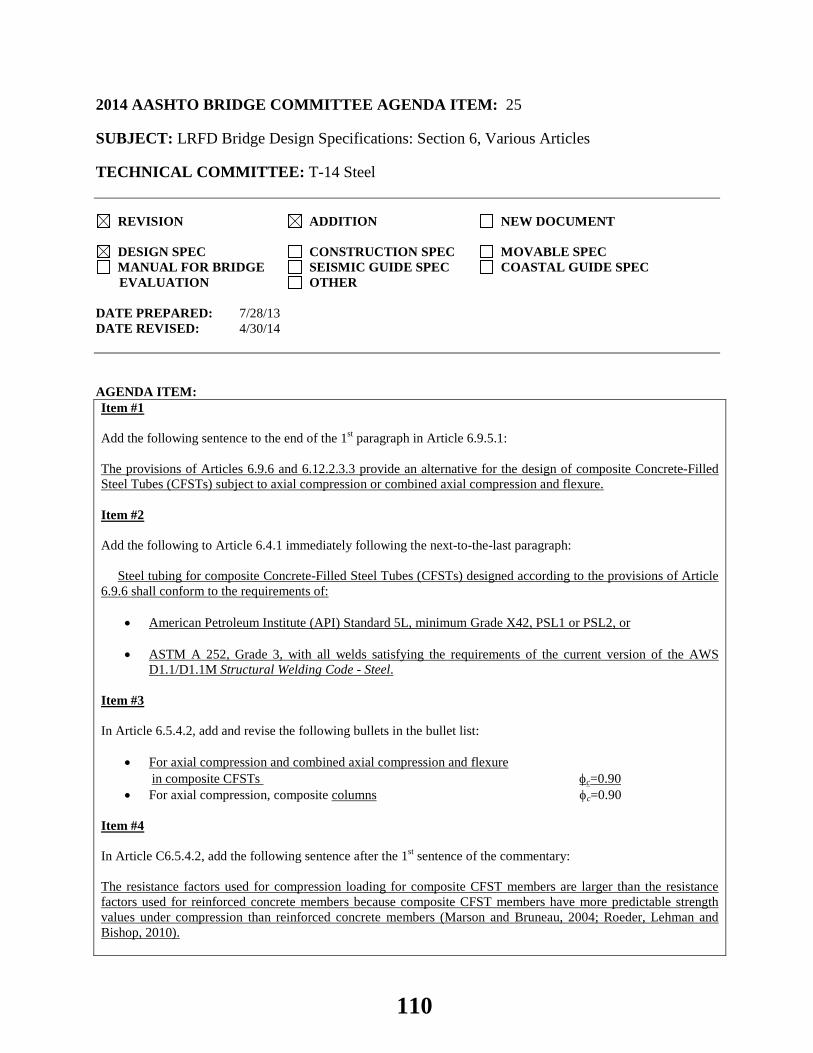
2014 AASHTO BRIDGE COMMITTEE AGENDA ITEM: 25 SUBJECT: LRFD Bridge Design Specifications: Section 6, Various Articles TECHNICAL COMMITTEE: T-14 Steel
REVISION ADDITION NEW DOCUMENT
DESIGN SPEC CONSTRUCTION SPEC MOVABLE SPEC MANUAL FOR BRIDGE SEISMIC GUIDE SPEC COASTAL GUIDE SPEC
EVALUATION OTHER DATE PREPARED: 7/28/13 DATE REVISED: 4/30/14 AGENDA ITEM:Item #1 Add the following sentence to the end of the 1st paragraph in Article 6.9.5.1: The provisions of Articles 6.9.6 and 6.12.2.3.3 provide an alternative for the design of composite Concrete-Filled Steel Tubes (CFSTs) subject to axial compression or combined axial compression and flexure. Item #2 Add the following to Article 6.4.1 immediately following the next-to-the-last paragraph: Steel tubing for composite Concrete-Filled Steel Tubes (CFSTs) designed according to the provisions of Article 6.9.6 shall conform to the requirements of:
• American Petroleum Institute (API) Standard 5L, minimum Grade X42, PSL1 or PSL2, or
• ASTM A 252, Grade 3, with all welds satisfying the requirements of the current version of the AWS D1.1/D1.1M Structural Welding Code - Steel.
Item #3 In Article 6.5.4.2, add and revise the following bullets in the bullet list:
• For axial compression and combined axial compression and flexure in composite CFSTs φc=0.90 • For axial compression, composite columns φc=0.90
Item #4 In Article C6.5.4.2, add the following sentence after the 1st sentence of the commentary: The resistance factors used for compression loading for composite CFST members are larger than the resistance factors used for reinforced concrete members because composite CFST members have more predictable strength values under compression than reinforced concrete members (Marson and Bruneau, 2004; Roeder, Lehman and Bishop, 2010).
110
Item #5 Revise the 1st sentence of Article 6.9.2.2 as follows:
Except as permitted otherwise in Articles 6.9.4.4 and 6.9.6.3, the axial compressive load, Pu, and concurrent moments, Mux and Muy, calculated for the factored loadings by elastic analytical procedures shall satisfy the following relationship: Item #6 Add a new Article 6.9.6 and associated commentary as follows: 6.9.6—Composite Concrete-Filled Steel Tubes (CFSTs)
6.9.6.1—General
The provisions of this Article, along with Article 6.12.2.3.3, provide an alternative method for the design of composite CFSTs subject to axial compression or for combined axial compression and flexure. CFSTs expected to develop full plastic hinging of the composite section as a result of a seismic event shall satisfy the provisions of the Guide Specifications for LRFD Seismic Bridge Design (AASHTO, 2011). The provisions of this Article shall apply to composite CFSTs with or without internal reinforcement. C6.9.6.1
CFSTs are primarily used for piles, drilled shafts, piers or columns, and other structural members subject to significant compression only or significant compression and flexure, and are efficient members for such applications. The provisions for the design of composite CFSTs contained herein may be used as an alternative to the provisions of Articles 6.9.5 and 6.12.2.3.2, which are intended for applications where full composite action is not deemed necessary. Research demonstrates that Articles 6.9.5 and 6.12.2.3.2 do not assure full composite action (Robinson et al. 2012, Lehman and Roeder 2012). Extensive research on composite CFSTs has been completed since the provisions of Article 6.9.5 were developed (Goode and Lam, 2011; Gourley et al., 2001). The provisions specified in Article 6.9.6 reflect the results of much of that research, reduce uncertainty and increase the accuracy of the prediction of the engineering properties of these members, and are similar to the AISC (2010) CFST provisions. The provisions contained in the Guide Specifications for LRFD Seismic Bridge Design (AASHTO, 2011) govern for the design of CFSTs expected to undergo full plastic hinging of the composite section under a seismic event. Experiments show that the resistance provided by the steel tube is much greater than that provided by internal reinforcement because the tube has a larger moment arm and is placed at the optimal location (Roeder and Lehman, 2012). Further, internal reinforcement may interfere with placement of the concrete fill and increase construction time.
6.9.6.2—Limitations
The following requirements shall be satisfied:
• Circular steel tubes shall be used.
• Spiral welded tubes formed from coil steel, straight-seam welded tubes formed from flat plates, or seamless pipes shall be used.
• Steel tubes with straight seam welds shall be permitted for CFSTs for all applications where the outside diameter is 24.0 in. or less. Steel tubes with straight seam welds shall be permitted for tubes larger than 24.0 in. in diameter if the concrete fill is designed with the addition of a low-shrinkage admixture to achieve a maximum of 0.04 percent shrinkage at 28 days, as tested in accordance with ASTM C157 Modified Standard Test Method for Length Change of Hardened Hydraulic-Cement Mortar.
• The wall thickness of the steel tube shall satisfy:
111
ystFE
tD 15.0≤ (6.9.6.2-1)
where:
D = outside diameter of the steel tube (in.) E = elastic modulus of steel tube (ksi) Fyst = specified minimum yield strength of steel tube (ksi) t = wall thickness of the steel tube (in.)
• The specified minimum 28-day compressive strength of the concrete shall be the greater of 3.0 ksi and 0.075Fyst, where Fyst is the specified minimum yield strength of the steel tube.
• CFSTs should not be used as pure flexural members.
C6.9.6.2 Circular CFSTs provide continuous confinement of the concrete, which is superior to that achieved with
rectangular CFSTs. Rectangular steel tubes are not included in these provisions. Large diameter tubes are required for most components in bridge applications. These are commonly formed by
one of two methods. Coil steel may be unrolled in a helical fashion to form a spirally welded tube. The spiral welds are made as butt joints and formed from both the inside and outside of the tube by the double submerged arc process. The spiral welds are subjected to direct stresses under axial load and flexure, and therefore they are essential for developing CFST resistance. Good performance is assured if proper weld metal and processes are employed and the minimum tensile strength of the weld metal matches the yield strength of the steel tube. The welds may also be inspected by ultrasonic or radiographic methods over the entire length of the weld if increased quality control is needed. This spiral weld process is limited to tubes with wall thickness of about 1.0 in. or less and diameters greater than about 20.0 in. Minimum requirements for these welds are provided in ASTM A 252 and API Specification 5L as appropriate.
The limiting diameter-to-thickness ratio given by Eq. 6.9.6.2-1 is commonly used for CFSTs and is the design limit for a compact composite section as specified in AISC (2010) for CFSTs. This limit has been shown to experimentally allow CFSTs to achieve the full plastic capacity while also providing substantial inelastic deformation capacity (Roeder, Lehman and Bishop, 2010). CFST piles may require a larger thickness and therefore a smaller D/t ratio than that suggested by Eq. 6.9.6.2-1 as a result of driving requirements.
The limits on the compressive strength of the concrete to the yield stress on the steel are required because research has shown that the benefits of composite action are reduced outside these limits.
Research shows that two mechanisms, mechanical transfer caused by slight projection of the spiral weld into the concrete fill and friction caused by contact stress between the steel and concrete, provide bond transfer between the steel tube and the concrete fill. For a spirally welded tube, mechanical action is present even if a low shrinkage concrete is not used. This is not the case for a straight-seam welded tube for which limited bond is present when conventional concrete is used. The use of a low-shrinkage admixture will enhance the bond capacity, particularly for larger diameter tubes. The detrimental effects of shrinkage are less significant with smaller diameter tubes. In addition, binding action resulting from bending enhances bond shear stress transfer between the steel tube and the concrete fill. This binding action assures adequate shear transfer without any internal connectors. Therefore, in cases where full composite action is deemed necessary and straight-seam welded tubes are used, the low shrinkage concrete requirements specified herein are required only for larger diameter tubes.
6.9.6.3—Combined Axial Compression and Flexure
6.9.6.3.1—General The axial compressive load, Pu, and concurrent moment, Mu, calculated for the factored loadings by elastic
analytical procedures shall satisfy the factored stability-based P-M interaction relationship. The factored interaction resistance curve shall be developed by applying the resistance factor, φc, for combined axial compression and flexure in composite CFSTs specified in Article 6.5.4.2 to the nominal stability-based P-M
112
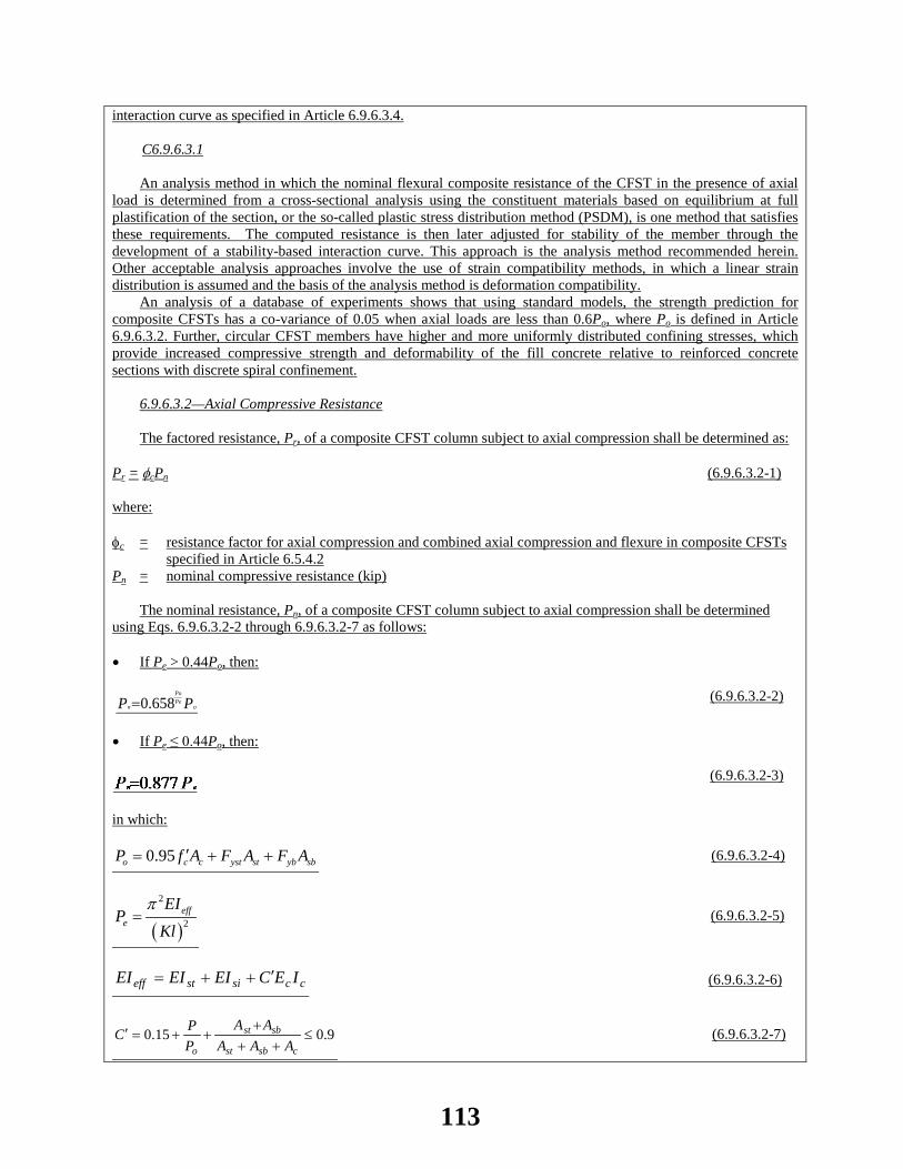
interaction curve as specified in Article 6.9.6.3.4. C6.9.6.3.1
An analysis method in which the nominal flexural composite resistance of the CFST in the presence of axial load is determined from a cross-sectional analysis using the constituent materials based on equilibrium at full plastification of the section, or the so-called plastic stress distribution method (PSDM), is one method that satisfies these requirements. The computed resistance is then later adjusted for stability of the member through the development of a stability-based interaction curve. This approach is the analysis method recommended herein. Other acceptable analysis approaches involve the use of strain compatibility methods, in which a linear strain distribution is assumed and the basis of the analysis method is deformation compatibility.
An analysis of a database of experiments shows that using standard models, the strength prediction for composite CFSTs has a co-variance of 0.05 when axial loads are less than 0.6Po, where Po is defined in Article 6.9.6.3.2. Further, circular CFST members have higher and more uniformly distributed confining stresses, which provide increased compressive strength and deformability of the fill concrete relative to reinforced concrete sections with discrete spiral confinement.
6.9.6.3.2—Axial Compressive Resistance
The factored resistance, Pr, of a composite CFST column subject to axial compression shall be determined as:
Pr = φcPn (6.9.6.3.2-1) where: φc = resistance factor for axial compression and combined axial compression and flexure in composite CFSTs
specified in Article 6.5.4.2 Pn = nominal compressive resistance (kip)
The nominal resistance, Pn, of a composite CFST column subject to axial compression shall be determined using Eqs. 6.9.6.3.2-2 through 6.9.6.3.2-7 as follows:
• If Pe > 0.44Po, then: PP o
PePo
n 658.0= (6.9.6.3.2-2)
• If Pe ≤ 0.44Po, then:
(6.9.6.3.2-3)
in which:
0.95o c c yst st yb sbP f A F A F A′= + + (6.9.6.3.2-4)
( )
2
2eff
e
EIP
Klπ
= (6.9.6.3.2-5)
ccsisteff IECEIEIEI ′++= (6.9.6.3.2-6)
9.015.0 ≤++
+++=′
csbst
sbst
o AAAAA
PPC (6.9.6.3.2-7)
113
where: Ast = cross-sectional area of the steel tube (in.2) Asb = total cross-sectional area of the internal reinforcement bars (in.2) Ac = net cross-sectional area of the concrete (in.2) Ec = elastic modulus of the concrete (ksi) E = elastic modulus of the steel tube and the internal steel reinforcement (ksi) EIeff = effective composite flexural cross-sectional stiffness of the CFST (kip-in2) Fyst = specified minimum yield strength of the steel tube (ksi) Fyb = specified minimum yield strength of the internal steel reinforcing bars (ksi) f'c = specified minimum 28-day compressive strength of the concrete (ksi) Ic = uncracked moment of inertia of the concrete about the centroidal axis (in.4) Ist = moment of inertia of the steel tube about the centroidal axis (in.4) Isi = moment of inertia of the internal steel reinforcement about the centroidal axis (in.4) K = effective length coefficient as specified in Article 4.6.2.5 l = unbraced length of the column (in.) P = applied unfactored axial dead load (kips) Pe = Euler buckling load (kips) Pn = nominal compressive resistance (kips) Po = maximum compressive load resistance of the column without consideration of buckling (kips)
C6.9.6.3.2 The procedure for designing composite CFST columns subject to axial compression is similar to that used for
the design of steel columns, except that a composite resistance and effective flexural stiffness, EIeff, are employed. The effective flexural stiffness increases with increasing compressive load, which suppresses cracking in the concrete fill, and therefore, C' is a function of the axial load. The flexural stiffness values provided by Eqs. 6.9.6.3.2-6 and 6.9.6.3.2-7 correspond to approximately 90 percent of the maximum resistance of the member, since this provides a conservative estimate of the buckling load. The flexural stiffness equations have been developed by comparison with past experimental results on composite CFSTs where the members have been loaded to loss of lateral load carrying capacity. Experiments show that this estimate is more accurate with smaller variance or standard deviation than that provided by other commonly used methods (Marson and Bruneau, 2004; Roeder, Lehman and Bishop, 2010).
6.9.6.3.3—Nominal Flexural Composite Resistance The nominal flexural composite resistance, Mn, of circular CFSTs as a function of the nominal axial resistance,
Pn, shall be determined as specified in Article 6.12.2.3.3.
6.9.6.3.4—Nominal Stability –Based Interaction Curve
The stability-based P-M interaction curve of CFSTs shall be constructed by joining points A′, A′′, D and B, as illustrated in Figure 6.9.6.3.4-1, where:
• Point A is Po, determined as specified in Article 6.9.6.3.2.
• Point A′ is obtained by multiplying the axial load associated with point A by the ratio, Pn/Po, where Pn is
determined as specified in Article 6.9.6.3.2.
• Point A′′ is the intersection of the material-based interaction curve determined as specified in Article 6.12.2.3.3 and a horizontal line through Point A′.
• Point B is the composite plastic moment resistance without an axial load, Mo.
• Point C corresponds to the axial force, PC, on the material-based interaction curve determined as specified
114
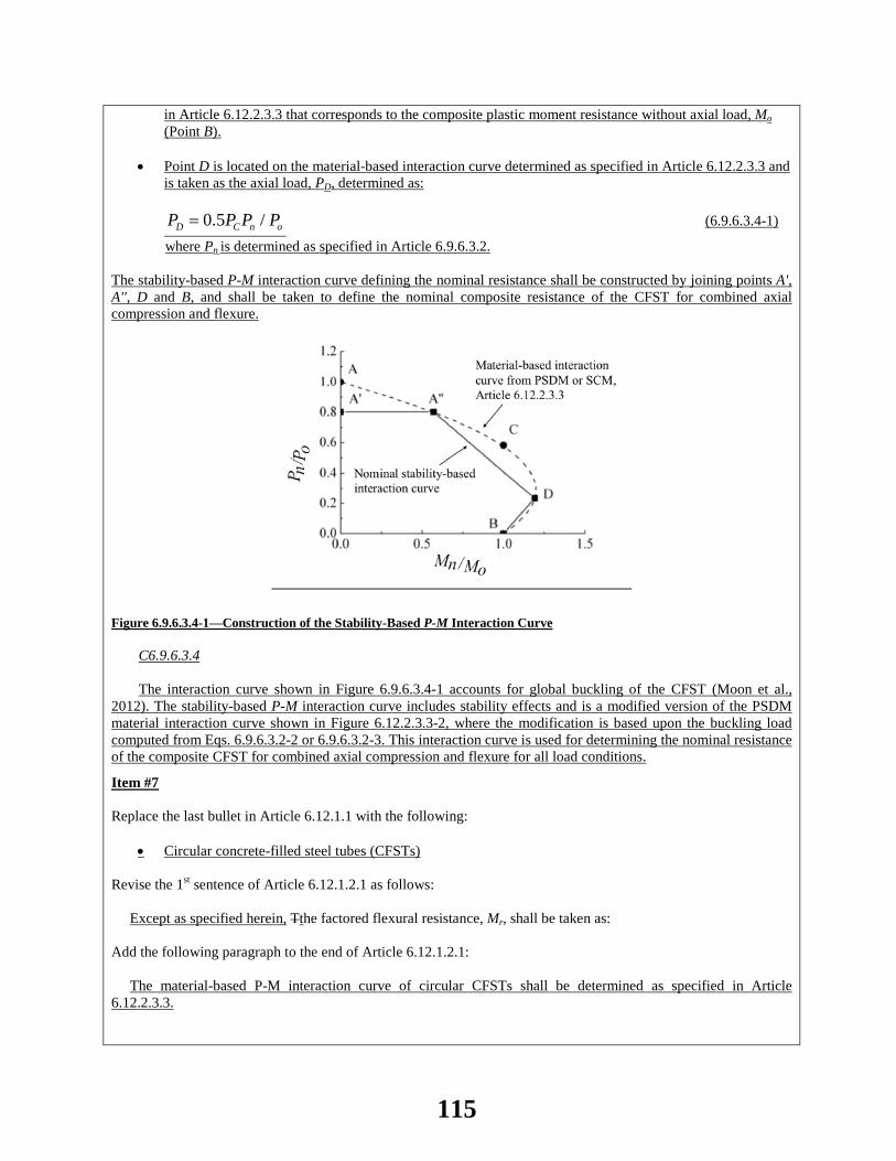
in Article 6.12.2.3.3 that corresponds to the composite plastic moment resistance without axial load, Mo (Point B).
• Point D is located on the material-based interaction curve determined as specified in Article 6.12.2.3.3 and
is taken as the axial load, PD, determined as:
0.5 /D C n oP P P P= (6.9.6.3.4-1)
where Pn is determined as specified in Article 6.9.6.3.2.
The stability-based P-M interaction curve defining the nominal resistance shall be constructed by joining points A', A'', D and B, and shall be taken to define the nominal composite resistance of the CFST for combined axial compression and flexure.
Figure 6.9.6.3.4-1—Construction of the Stability-Based P-M Interaction Curve
C6.9.6.3.4
The interaction curve shown in Figure 6.9.6.3.4-1 accounts for global buckling of the CFST (Moon et al., 2012). The stability-based P-M interaction curve includes stability effects and is a modified version of the PSDM material interaction curve shown in Figure 6.12.2.3.3-2, where the modification is based upon the buckling load computed from Eqs. 6.9.6.3.2-2 or 6.9.6.3.2-3. This interaction curve is used for determining the nominal resistance of the composite CFST for combined axial compression and flexure for all load conditions.
Item #7 Replace the last bullet in Article 6.12.1.1 with the following:
• Circular concrete-filled steel tubes (CFSTs) Revise the 1st sentence of Article 6.12.1.2.1 as follows: Except as specified herein, Tthe factored flexural resistance, Mr, shall be taken as: Add the following paragraph to the end of Article 6.12.1.2.1: The material-based P-M interaction curve of circular CFSTs shall be determined as specified in Article 6.12.2.3.3.
115

Revise Article 6.12.1.2.2 as follows: Except as specified herein, tThe provisions of Article 6.8.2.3 for combined axial tension and flexure or the provisions of Article 6.9.2.2 for combined axial compression and flexure shall apply, as applicable. In the “where” list for Eq. 6.12.1.2.3a-1, add the word “noncomposite” in front of the words “circular tubes” in the definition of Vn. Revise the 1st sentence of Article 6.12.1.2.3c as follows: For noncomposite circular tubes, including round HSS, the nominal shear resistance, Vn, shall be taken as: Revise the first sentence of Article C6.12.1.2.3c as follows: The provisions for noncomposite circular tubes, including round Hollow Structural Sections (HSS), subject to transverse shear are based on the provisions for local buckling of cylinders due to torsion. Revise Article 6.12.2.1 as follows: Except as specified herein, provisions for lateral torsional buckling need not be applied to composite members, noncomposite box-shaped members, noncomposite I- and H-shaped members bent about their weak axis, and noncomposite circular tubes. Revise the 1st sentence of Article 6.12.2.2.3 as follows: For noncomposite circular tubes, including round HSS, the nominal flexural resistance shall be taken as the smaller value based on yielding or local buckling, as applicable. Add the word “noncomposite” in front of the words “circular tubes” in the first sentence of Article C6.12.2.2.3. Item #8 Add a new Article 6.12.2.3.3 and associated commentary as follows: 6.12.2.3.3—Composite Concrete-Filled Steel Tubes (CFSTs)
The material-based nominal P-M interaction curve of circular CFSTs that satisfy the limitations in Article 6.9.6.2 shall be computed using one of the following methods:
• the plastic stress distribution method (PSDM), or
• the strain compatibility method (SCM).
C6.12.2.3.3
The PSDM and SCM methods are permitted for evaluating the resistance of CFST members. The resistances obtained in experiments performed by a wide range of researchers on CFST members have been compared to the resistances predicted by the PSDM and SCM methods. Both methods provided conservative estimates of the resistance of CFST members. The comparisons were based upon the measured bending moment with a given applied axial load. The experiments showed that the CFST members developed 24 percent larger bending moment than predicted by the PSDM and 65 percent larger bending moment than predicted by the SCM. The standard deviation of the measured bending moment was 18 percent of the mean bending moment for the PSDM method and 114 percent of the mean bending moment for the SCM method. While the SCM has considerably more scatter in its predicted resistance, it provides estimates of curvature and nonlinear deformation; the PSDM does not provide any information on strain or deformation (Marson and Bruneau, 2004; Roeder, Lehman and Bishop, 2010).
The PSDM is recognized in AISC (2010) and in the Guide Specifications for LRFD Seismic Bridge Design
116
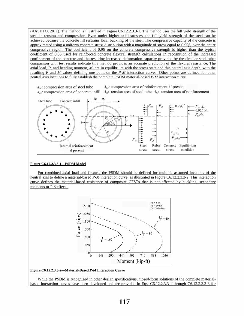
(AASHTO, 2011). The method is illustrated in Figure C6.12.2.3.3-1. The method uses the full yield strength of the steel in tension and compression. Even under higher axial stresses, the full yield strength of the steel can be achieved because the concrete fill restrains local buckling of the steel. The compressive capacity of the concrete is approximated using a uniform concrete stress distribution with a magnitude of stress equal to 0.95f'c over the entire compressive region. The coefficient of 0.95 on the concrete compressive strength is higher than the typical coefficient of 0.85 used for reinforced concrete flexural strength calculations in recognition of the increased confinement of the concrete and the resulting increased deformation capacity provided by the circular steel tube; comparison with test results indicate this method provides an accurate prediction of the flexural resistance. The axial load, P, and bending moment, M, are in equilibrium with the stress state and this neutral axis depth, with the resulting P and M values defining one point on the P-M interaction curve. Other points are defined for other neutral axis locations to fully establish the complete PSDM material-based P-M interaction curve.
Figure C6.12.2.3.3-1—PSDM Model
For combined axial load and flexure, the PSDM should be defined for multiple assumed locations of the
neutral axis to define a material-based P-M interaction curve, as illustrated in Figure C6.12.2.3.3-2. This interaction curve defines the material-based resistance of composite CFSTs that is not affected by buckling, secondary moments or P-δ effects.
Figure C6.12.2.3.3-2—Material-Based P-M Interaction Curve While the PSDM is recognized in other design specifications, closed-form solutions of the complete material-
based interaction curves have been developed and are provided in Eqs. C6.12.2.3.3-1 through C6.12.2.3.3-8 for
117
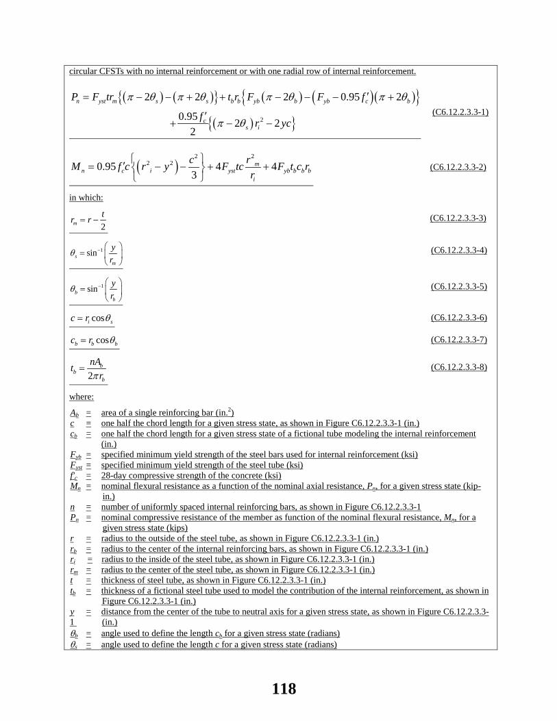
circular CFSTs with no internal reinforcement or with one radial row of internal reinforcement.
( ) ( ){ } ( ) ( ) ( ){ }( ){ }2
2 2 2 0.95 2
0.95 2 22
n yst m s s b b yb b yb c b
cs i
P F tr t r F F f
f r yc
π θ π θ π θ π θ
π θ
′= − − + + − − − +
′+ − −
(C6.12.2.3.3-1)
( )2 2
2 20.95 4 43
mn c i yst yb b b b
i
c rM f c r y F tc F t c rr
′= − − + +
(C6.12.2.3.3-2)
in which:
2mtr r= − (C6.12.2.3.3-3)
1sinsm
yr
θ − =
(C6.12.2.3.3-4)
1sinbb
yr
θ − =
(C6.12.2.3.3-5)
cosi sc r θ= (C6.12.2.3.3-6)
cosb b bc r θ= (C6.12.2.3.3-7)
2b
bb
nAtrπ
= (C6.12.2.3.3-8)
where:
Ab = area of a single reinforcing bar (in.2) c = one half the chord length for a given stress state, as shown in Figure C6.12.2.3.3-1 (in.) cb = one half the chord length for a given stress state of a fictional tube modeling the internal reinforcement (in.) Fyb = specified minimum yield strength of the steel bars used for internal reinforcement (ksi) Fyst = specified minimum yield strength of the steel tube (ksi) f'c = 28-day compressive strength of the concrete (ksi) Mn = nominal flexural resistance as a function of the nominal axial resistance, Pn, for a given stress state (kip-
in.) n = number of uniformly spaced internal reinforcing bars, as shown in Figure C6.12.2.3.3-1 Pn = nominal compressive resistance of the member as function of the nominal flexural resistance, Mn, for a
given stress state (kips) r = radius to the outside of the steel tube, as shown in Figure C6.12.2.3.3-1 (in.) rb = radius to the center of the internal reinforcing bars, as shown in Figure C6.12.2.3.3-1 (in.) ri = radius to the inside of the steel tube, as shown in Figure C6.12.2.3.3-1 (in.) rm = radius to the center of the steel tube, as shown in Figure C6.12.2.3.3-1 (in.) t = thickness of steel tube, as shown in Figure C6.12.2.3.3-1 (in.) tb = thickness of a fictional steel tube used to model the contribution of the internal reinforcement, as shown in Figure C6.12.2.3.3-1 (in.) y = distance from the center of the tube to neutral axis for a given stress state, as shown in Figure C6.12.2.3.3-1 (in.) θb = angle used to define the length cb for a given stress state (radians) θs = angle used to define the length c for a given stress state (radians)
118

Smaller tD / values result in larger resistance because the area of steel is larger than a tube with the same diameter and smaller thickness, which of course would have a larger D/t ratio. Larger tD / ratios result in significantly increased normalized flexural resistances for modest compressive loads relative to the flexural resistance corresponding to zero axial load because of the increased contribution of the concrete fill.
In the expressions, a positive value of P implies a compressive force, and y and θ are positive according to the sign convention shown in Figure C6.12.2.3.3-1. The P-M material-based interaction curve is generated by solving the equations for discrete values of y, and connecting those points where y varies between plus and minus ri. For the case in which internal reinforcement is not present, the variables Ab and tb are equal to zero and several terms do not contribute to the resistance. Item #9 Insert the following references in Article 6.17: API. 2012. API Specification 5L – Specification for Line Pipe, 45th Edition, American Petroleum Institute, Washington, D.C. AWS. 2010. Structural Welding Code – Steel (AWS D1.1/D1.1M), American Welding Society, Miami, FL. Goode, C.D. and Lam, D. 2011. “Concrete-Filled Steel Tube Columns – Tests Compared with Eurocode 4,” Composite Construction in Steel and Concrete VI, Special publication, ASCE, Reston, VA (proceedings of the 6th ECI Conference on Composite Construction, Devils Thumb Ranch, CO, July 20-24, 2008). Gourley, B.C., Tort, C., Hajjar, J.F., and Schiller, P.H. 2001. “A Synopsis of Studies on the Monotonical and Cyclic Behavior of Concrete-Filled Steel Tube Beam-Columns,” Structural Engineering Report ST-01-4, Dept. of Civil Engineering, University of Minnesota, Minneapolis, MN. Lehman, D.E., and Roeder, C.W. 2012. “Rapid Construction of Bridge Piers with Improved Seismic Performance,” Report CA12-1972, California Department of Transportation, Sacramento, CA. Marson, J. and Bruneau, M. 2004. “Cyclic Testing of Concrete-Filled Circular Steel Bridge Piers Having Encased Fixed-Base Details,” Journal of Bridge Engineering, Vol 9. No 1, pp. 14-23. Moon, Jiho, Lehman, D.E., Roeder, C.W, and Lee, H. K. 2012. “Strength of Circular Concrete-Filled Tubes (CFT) with and without Internal Reinforcement under Combined Loading,” Journal of Structural Engineering, ASCE, Reston, VA, DOI Information: 10.1061/(ASCE)ST.1943-541X.0000788. Robinson, B., Suarez, V., Gabr, M.A., and Kowalsky, M. 2012. “Simplified Lateral Analysis of Deep Foundation Bridge Bents: Driven Pile Case Study,” Journal of Bridge Engineering, ASCE, Vol 16, No 4, pp. 558-569. Roeder, C.W., and Lehman, D.E. 2012. "Initial Investigation of Reinforced Concrete Filled Tubes for use in Bridge Foundations," Research Report WA-RD 776.1, Washington Department of Transportation, Olympia, WA, June 2012. Roeder, C.W., Lehman, D.E. and Bishop E. 2010. “Strength and Stiffness of Circular Concrete Filled Tubes," ASCE, Journal of Structural Engineering, Vol 135, No. 12, pp. 1545-1553. Roeder, C.W., Lehman, D.E., and Thody, R. 2009. "Composite Action in CFT Components and Connections," AISC, Engineering Journal, Vol. 46, No. 4, pp. 229-242. Item #10 Add the following definitions to Article 6.2:
119

Composite Concrete-Filled Steel Tube (CFST)—A concrete filled steel tube (CFST) is a composite member consisting of a circular steel tube and concrete fill, which may be used for piers, columns, piles or drilled shafts. There are typically no shear connectors or internal reinforcement in the concrete fill, since composite action is assured through the provisions of Articles 6.9.6 and 6.12.2.3.3. Plastic Stress Distribution Method (PSDM)—The plastic stress distribution method is an equilibrium method used to define the nominal composite flexural resistance of CFST members prior to consideration of stability. This method is provided as an alternative to the strain compatibility method. Strain Compatibility Method (SCM)—The strain compatibility method is used to evaluate the nominal composite flexural resistance of CFSTs. Modify the Notation in Article 6.3 as follows: Ab = projected bearing area on a pin plate (in.2); area of a single reinforcing bar in a composite concrete-
filled steel tube (in.2); cross-sectional area of a bolt (in.2) (6.8.7.2) (C6.12.2.3.3) (6.13.2.7) Ac = area of concrete (in.2); net cross-sectional area of the concrete in a composite concrete-filled steel tube
(in.2); area of the concrete deck (in.2) (6.9.5.1) (6.9.6.3.2) (D6.3.2) Asb = total cross-sectional area of the internal reinforcement bars in a composite concrete-filled steel tube
(in.2) (6.9.6.3.2) Ast = cross-sectional area of the steel tube in a composite concrete-filled steel tube (in.2) (6.9.6.3.2) CFST = concrete-filled steel tube (in.2) (6.4.1) (6.5.4.2) (C6.5.4.2) (6.9.6) (6.12.1.2.1) (6.12.2.3.3)
(C6.12.2.3.3) c = distance from the center of the longitudinal reinforcement to the nearest face of a concrete-encased
shape in the plane of bending (in.); one half the chord length for a given stress state in a composite concrete-filled steel tube (in.) (6.12.2.3.1) (C6.12.2.3.3)
cb = one half the chord length for a given stress state of a fictional tube modeling the internal reinforcement in a composite concrete-filled steel tube (in.) (C6.12.2.3.3)
D = diameter of a pin (in.); clear distance between flanges (in.); outside diameter of a circular Hollow Structural Section (HSS) (in.); outside diameter of a circular steel tube (in.); outside diameter of tube (in.); outside diameter of the steel tube in a composite concrete-filled steel tube (in.); web depth (in.); depth of the web plate measured along the slope (in.); clear distance between the flanges less the inside corner radius on each side (in.) (6.7.6.2.1) (6.8.2.2) (6.9.4.2) (6.9.4.2.1) (6.9.6.2) (6.10.1.9.1) (6.11.9) (6.12.1.2.3c) (6.12.2.2.2) (6.12.2.2.3) (6.12.2.2.5)
E = modulus of elasticity of steel (ksi); elastic modulus of the steel tube in a composite concrete-filled steel tube (ksi); elastic modulus of the internal steel reinforcement in a composite concrete-filled steel tube (ksi) (6.7.7.3) (6.9.6.2) (6.9.6.3.2)
Ec = elastic modulus of the concrete in a composite concrete-filled steel tube (ksi); modulus of elasticity of concrete (ksi) (6.9.6.3.2) (6.10.1.1.1b)
EIeff = effective composite flexural cross-sectional stiffness of a composite concrete-filled steel tube (kip-in2) (6.9.6.3.2)
Fyb = specified minimum yield strength of the internal steel reinforcement in a composite concrete-filled steel tube (ksi) (6.9.6.3.2)
Fyst = specified minimum yield strength of the steel tube in a composite concrete-filled steel tube (ksi) (6.9.6.2) (6.9.6.3.2)
f′c = specified minimum specified 28-day compressive strength of concrete (ksi); specified minimum 28-day compressive strength of the concrete in a composite concrete-filled steel tube (ksi) (6.9.5.1) (6.9.6.3.2) (6.10.4.2.1)
Ic = uncracked moment of inertia of the concrete in a composite concrete-filled steel tube about the centroidal axis (in.4) (6.9.6.3.2)
Isi = moment of inertia of the internal steel reinforcement in a composite concrete-filled steel tube about the centroidal axis (in.4) (6.9.6.3.2)
Ist = moment of inertia of the steel tube in a composite concrete-filled steel tube about the centroidal axis (in.4) (6.9.6.3.2)
K = effective length factor; effective length factor in the plane of buckling determined as specified in Article 4.6.2.5; effective length factor as specified in Article 4.6.2.5; effective column length factor
120

taken as 0.50 for chord splices (6.9.3) (6.9.4.1.2) (6.9.6.3.2) (6.14.2.8.6) ℓ = unbraced member length (in.); distance between the work points of the joints measured along the
length of the angle (in.); unbraced length in the plane of buckling (in.); unbraced length of a composite concrete-filled steel tube column (in.) (6.8.4) (6.9.4.1.2) (6.9.4.4) (6.9.6.3.2)
Mn = nominal flexural resistance of a section (k-in.); nominal flexural resistance of a composite concrete-filled steel tube (k-in.) (6.10.7.1.1) (C6.12.2.3.3)
n = number of cycles per truck passage; modular ratio; number of shear connectors in a cross-section; minimum number of shear connectors over the region under consideration; number of equally spaced longitudinal flange stiffeners; number of uniformly spaced internal reinforcing bars in a composite concrete-filled steel tube; number of bolts in one vertical row of a web splice (6.6.1.2.5) (6.9.5.1) (6.10.10.1.2) (6.10.10.4.1) (6.11.8.2.3) (C6.12.2.3.3) (C6.13.6.1.4b)
P = applied unfactored axial dead load for a composite concrete-filled steel tube (kip); total nominal shear force in the concrete deck for the design of the shear connectors at the strength limit state (kip) (6.9.6.3.2) (6.10.10.4.1)
Pe = elastic critical buckling resistance determined as specified in Article 6.9.4.1.2 for flexural buckling, as specified in Article 6.9.4.1.3 for torsional bucking or flexural-torsional buckling, as applicable (kip); Euler buckling load for a composite concrete-filled steel tube (kip); and elastic critical buckling resistance determined as specified in Article 6.14.2.8.4 for gusset plate buckling (kip) (6.9.4.1.1) (6.9.6.3.2) (6.14.2.8.4)
Pn = nominal bearing resistance on pin plates (kip); nominal axial compressive resistance (kip); total longitudinal force in the concrete deck over an interior support for the design of the shear connectors at the strength limit state, taken as the lesser of either P1n or P2n (kip); nominal compressive resistance of a composite concrete-filled steel tube (kip); nominal compressive resistance of an idealized Whitmore section (kip) (6.8.7.2) (6.9.2.1) (6.9.6.3.2) (6.10.10.4.2) (C6.12.2.3.3) (6.14.2.8.4)
Po = equivalent nominal yield resistance = QFyAg (kips); maximum compressive load resistance of a composite concrete-filled steel tube column without consideration of buckling (kip) (6.9.4.1.1) (6.9.6.3.2)
Pr = factored axial tensile or compressive resistance (kip); factored bearing resistance on pin plates (kip); factored compressive resistance of a composite concrete-filled steel tube (kip); factored axial resistance of bearing stiffeners (kip); factored compressive resistance of gusset plates (kip); factored axial compressive resistance of a steel pile (kip) (6.8.2.1) (6.8.7.2) (6.9.6.3.2) (6.10.11.2.4a) (6.14.2.8.4) (6.15.3.1)
r = minimum radius of gyration of a tension or compression member (in.); radius of gyration of a built-up member about an axis perpendicular to a perforated plate (in.); radius of gyration of a longitudinal web stiffener including an effective width of web taken about the neutral axis of the combined section (in.); radius to the outside of the steel tube in a composite concrete-filled steel tube (in.) (6.8.4) (6.9.4.3.2) (6.10.11.3.3) (C6.12.2.3.3)
rb = radius to the center of the internal reinforcing bars in a composite concrete-filled steel tube (in.) (C6.12.2.3.3)
ri = minimum radius of gyration of an individual component shape (in.); radius to the inside of the steel tube in a composite concrete-filled steel tube (in.) (C6.9.4.3.1) (C6.12.2.3.3)
rm = radius to the center of the steel tube in a composite concrete-filled steel tube (in.) (C6.12.2.3.3) t = thickness of plate or plates (in.); thickness of tube or wall (in.); wall thickness of the steel tube in a
composite concrete-filled steel tube (in.); thickness of the thinner outside plate or shape (in.); thickness of the connected material (in.); thickness of the thinnest connected part (in.); thickness of tube (in.); width of the rectangular bar parallel to the axis of bending (in.) (C6.7.4.3) (6.9.4.2.1) (6.9.6.2) (6.12.1.2.3c) (6.12.2.2.3) (6.12.2.2.7) (C6.12.2.3.3) (6.13.2.6.2) (6.13.2.9) (6.13.2.10.4)
tb = thickness of a fictional tube modeling the internal reinforcement in a composite concrete-filled steel tube (in.); thickness of the flange transmitting the concentrated force in a rigid-frame connection (in.) (C6.12.2.3.3) (6.13.7.2)
y = distance from the center of the steel tube to the neutral axis for a given stress state in a composite concrete-filled steel tube (in.) (C6.12.2.3.3)
θb = angle defining the length cb for a given stress state in a composite concrete-filled steel tube (radians) (C6.12.2.3.3)
θs = angle defining the length c for a given stress state in a composite concrete-filled steel tube (radians) (C6.12.2.3.3)
121

φc = resistance factor for axial compression and combined axial compression and flexure (6.5.4.2)
OTHER AFFECTED ARTICLES:None
BACKGROUND:This is the first major proposed update of the provisions for the design of concrete-filled steel tubes (CFSTs) in the AASHTO LRFD Bridge Design Specifications. The current design provisions are identical to those included in the original LRFD Draft Specification for CFSTs approximately 25 years ago. Thousands of CFST experiments have been completed in the US, Japan, China, Australia and Europe during the past 25 years, and significant changes have been made in other design specifications (particularly the AASHTO Guide Specifications for LRFD Seismic Bridge Design and the AISC Design Specifications) for CFSTs. The proposed revisions and additions, which provide an improved alternative approach for the design of circular composite CFSTs, are based upon other provisions used for CFST construction and the comparison with the vast body of experimental results on composite CFSTs that have been developed in the last 25 years.
ANTICIPATED EFFECT ON BRIDGES:These provisions provide an improved alternative design approach for circular composite concrete filled steel tubes (CFSTs) used for bridge piers, piles, drilled shafts and other structural elements in applications where full plastic hinging of the composite section under a seismic event is not a concern. The use of composite CFST piers permits rapid construction of the pier, since no formwork or internal reinforcement is required. Further, composite CFST piers result in the less weight and material since the diameter of the pier will be 25% to 35% smaller than a comparable reinforced concrete pier of the same strength and stiffness.
REFERENCES: Goode, C.D. and Lam, D. (2011) “Concrete-Filled Steel Tube Columns – Tests Compared with Eurocode 4,” Composite Construction in Steel and Concrete VI, Special publication, ASCE, Reston, VA (proceedings of the 6th ECI Conference on Composite Construction, Devils Thumb Ranch, CO, July 20-24, 2008) Gourley, B.C., Tort, C., Hajjar, J.F., and Schiller, P.H., “A Synopsis of Studies on the Monotonical and Cyclic Behavior of Concrete-Filled Steel Tube Beam-Columns,” Structural Engineering Report ST-01-4, Dept. of Civil Engineering, University of Minnesota, Minneapolis, MN. Lehman, D.E., and Roeder, C.W (2012) "Rapid Construction of Bridge Piers with Improved Seismic Performance," California Department of Transportation Report CA12-1972, Sacramento, CA. Marson, J. and Bruneau, M. (2004) "Cyclic Testing of Concrete-Filled Circular Steel Bridge Piers Having Encased Fixed-Base Details," Journal of Bridge Engineering, Vol 9. No 1, pp 14-23. Moon, Jiho, Lehman, D.E., Roeder, C.W, and Lee, H-K, (2012) "Strength of Circular Concrete-Filled Tubes (CFT) with and without Internal Reinforcement under Combined Loading," Journal of Structural Engineering, ASCE, Reston, VA, DOI Information: 10.1061/(ASCE)ST.1943-541X.0000788. Robinson, B., Suarez, V., Gabr, M.A., and Kowalsky (2012) “Simplified Lateral Analysis of Deep Foundation Bridge Bents: Driven Pile Case Study,” Journal of Bridge Engineering, ASCE, Vol 16, No 4, pgs 558-569 Roeder, C.W., and Lehman, D.E., (2012) "Initial Investigation of Reinforced Concrete Filled Tubes for use in Bridge Foundations," Research Report WA-RD 776.1, Washington Department of Transportation, Olympia, WA, June 2012.
122

Roeder, C.W., Lehman, D.E. and Bishop E. (2010),“Strength and Stiffness of Circular Concrete Filled Tubes," ASCE, Journal of Structural Engineering, Vol 135, No. 12, pgs 1545-53, Reston, VA. Roeder, C.W, Lehman, D.E., and Thody, R. (2009) "Composite Action in CFT Components and Connections," AISC, Engineering Journal, Vol. 46, No. 4, Chicago, IL, pgs 229-42.
OTHER: None
123

2014 AASHTO BRIDGE COMMITTEE AGENDA ITEM: 26 SUBJECT: LRFD Bridge Design Specifications: Section 6, Various Articles TECHNICAL COMMITTEE: T-14 Steel
REVISION ADDITION NEW DOCUMENT
DESIGN SPEC CONSTRUCTION SPEC MOVABLE SPEC MANUAL FOR BRIDGE SEISMIC GUIDE SPEC COASTAL GUIDE SPEC
EVALUATION OTHER DATE PREPARED: 2/5/14 DATE REVISED: AGENDA ITEM:Item #1 In Figure C6.10.9.1-1, revise the bottom right box of the flowchart as follows: Eq. 6.10.9.3.2-8 Reduced Tension-Field Action Item #2 Revise the 1st sentence of Article 6.10.9.2 as follows: The nominal shear resistance of unstiffened webs shall be taken as the shear-yielding or shear-buckling resistance as follows: Item #3 Revise the 2nd sentence of Article C6.10.9.2 as follows: The elastic shear-yielding or shear-buckling resistance is calculated as the product of the constant C specified in Article 6.10.9.3.2 times the plastic shear force, Vp, given by Eq. 6.10.9.2-2. Add the following to the end of Article C6.10.9.2: The nominal shear resistance is equal to the shear-yielding resistance when C is equal to 1.0; otherwise, the nominal shear resistance is equal to the shear-buckling resistance. In the “where” lists in Articles 6.10.9.2 and 6.10.9.3.3, change the definition of Vcr to “shear-yielding or shear-buckling resistance (kip)”. In the “where” lists in Articles 6.10.3.3 and 6.10.5.3, change the definition of Vcr to “shear-yielding or shear-buckling resistance determined from Eq. 6.10.9.3.3-1 (kip)”. Item #4 Revise the 1st two sentences of the 1st paragraph of Article 6.10.9.3.1 as follows:
124

The nominal shear resistance of transversely or transversely and longitudinally-stiffened interior web panels shall be taken as the postbuckling shear resistance due to tension-field action as specified in Articles 6.10.9.3.2. The nominal shear resistance of transversely or transversely and longitudinally-stiffened end web panels shall be taken as the shear-yielding or shear-buckling resistance as specified in Articles 6.10.9.3.3. Item #5 Revise the 1st paragraph of Article 6.10.11.1.3 as follows: For transverse stiffeners adjacent to web panels not subject to postbuckling tension-field action in which neither panel supports a shear force, Vu, larger than the factored shear buckling resistance, ϕvVcr, the moment of inertia, It, of the transverse stiffener shall satisfy the smaller of the following limits: Delete the definitions of ϕv, Vcr, Vp, Vu and C in the “where” list underneath Eq. 6.10.11.1.3-8. Add the following terms to the “where” list underneath Eq. 6.10.11.1.3-8: bt = width of the projecting stiffener element (in.) Fyw = specified minimum yield strength of the web (ksi) It1 = minimum moment of inertia of the transverse stiffener required for the development of the web shear-
buckling resistance (in.4) It2 = minimum moment of inertia of the transverse stiffener required for the development of the full web
postbuckling tension-field action resistance (in.4) tp = thickness of the projecting stiffener element (in.) Delete Eq. 6.10.11.1.3-7 and Eq. 6.10.11.1.3-8 (Note: subsequent Eqns. 6.10.11.1.3-9 and 6.10.11.1.3-10 will be re-numbered as instructed below.) Item #6 Revise the second paragraph of Article 6.10.11.1.3 as follows: For transverse stiffeners adjacent to web panels subject to postbuckling tension-field action in which the shear force, Vu, is larger than the factored shear buckling resistance, ϕvVcr, and thus the web postbuckling of tension-field resistance is required in one or both panels, the moment of inertia, It, of the transverse stiffeners shall satisfy: Revise Eq. 6.10.11.1.3-9 and re-number to Eq. 6.10.11.1.3-7 as follows: 𝐼𝑡 ≥ 𝐼𝑡1 + (𝐼𝑡2 − 𝐼𝑡1) � 𝑉𝑢−∅𝑣𝑉𝑐𝑟
∅𝑣𝑉𝑛−∅𝑣𝑉𝑐𝑟� (6.10.11.1.3-9)
𝐼𝑡 ≥ 𝐼𝑡1 + (𝐼𝑡2 − 𝐼𝑡1)𝜌𝑤 ___________________ (6.10.11.1.3-7) Re-number Eq. 6.10.11.1.3-10 to Eq. 6.10.11.1.3-8. Add the following “in which” list after Eq. 6.10.11.1.3-8 (i.e. the re-numbered Eq. 6.10.11.1.3-10): in which: • If both web panels adjacent to the stiffener are subject to postbuckling tension-field action, then:
ρw = maximum ratio of � 𝑉𝑢−∅𝑣𝑉𝑐𝑟∅𝑣𝑉𝑛−∅𝑣𝑉𝑐𝑟
� within the two web panels
125

• Otherwise:
ρw = ratio of � 𝑉𝑢−∅𝑣𝑉𝑐𝑟∅𝑣𝑉𝑛−∅𝑣𝑉𝑐𝑟
� within the one panel subject to postbuckling tension-field action
Vcr = shear-yielding or shear-buckling resistance of the web panel under consideration (kip) = CVp (6.10.11.1.3-9) Vp = plastic shear force (kip) = 0.58FywDtw (6.10.11.1.3-10) Revise the “where” list after Eq 6.10.11.1.3-8 (i.e the re-numbered Eq. 6.10.11.1.3-10) as follows: Vn = smaller of the nominal combined buckling and tension-field shear resistances of the adjacent web panels,
determined as specified in Article 6.10.9.3.2 (kip) ϕv = resistance factor for shear specified in Article 6.5.4.2 C = ratio of the shear-buckling resistance to the shear yield strength determined by Eq. 6.10.9.3.2-4, 6.10.9.3.2-
5, or 6.10.9.3.2-6, as applicable Vn = nominal postbuckling tension-field action resistance of the web panel under consideration determined as
specified in Article 6.10.9.3.2 (kip) Vu = maximum shear due to the factored loads in the web panel under consideration (kip) Item #7 In Article C6.10.11.1.3, revise the 1st sentence of the 1st paragraph as follows: For the web to adequately develop the shear-buckling resistance or the combined shear-buckling and postbuckling tension-field resistance as determined in Article 6.10.9, the transverse stiffener must have sufficient rigidity to maintain a vertical line of near zero lateral deflection along the line of the stiffener. In the 7th paragraph of Article C6.10.11.1.3, change both occurrences of the reference to Eq. 6.10.11.1.3-9 to Eq. 6.10.11.1.3-7, and change the reference to Eq. 6.10.11.1.3-10 to Eq. 6.10.11.1.3-8. Replace the references to "(Kim et al., 2004)" in the 1st, 3rd (twice), 5th and 7th paragraphs of Article C6.10.11.1.3 with "(Kim and White, 2013)". Item #8 Revise the Definitions in Article 6.2 as follows: End Panel—The end section of a truss or a web panel adjacent to the discontinuous end of a girder. Interior Panel—The interior section of a truss or a web panel not adjacent to the discontinuous end of a girder component. Web Panel—A length of girder web in-between adjacent transverse intermediate web stiffeners or a transverse intermediate web stiffener and a bearing stiffener. Web panels are classified as either end panels or interior panels. Item #9 Revise the Notation in Article 6.3 as follows: bt = projecting width of a transverse or bearing stiffener (in.); width of the projecting stiffener element (in.);
126
full width of the tension flange (in.) (6.10.11.1.2) (6.10.11.1.3) (D6.1) C = ratio of the shear-buckling resistance to the shear specified minimum yield strength (6.10.9.2) It1 = minimum moment of inertia of the transverse stiffener required for the development of the web shear
buckling resistance (in.4) (6.10.11.1.3) It2 = minimum moment of inertia of the transverse stiffener required for the development of the full web shear
buckling plus postbuckling tension-field action resistance (in.4) (6.10.11.1.3) Vcr = shear-yielding or shear-bucking resistance (kip); web shear-yielding or shear-buckling resistance of the
web panel under consideration (kip) (6.10.3.3) (6.10.11.1.3) Vn = nominal shear resistance (kip); nominal shear buckling plus postbuckling tension-field action resistance of
the web panel under consideration (kip) (6.10.9.1) (6.10.11.1.3) (6.12.1.2.3a) Vu = shear due to the factored loads (kip); maximum shear due to the factored loads in the web panel under
consideration (kip); vertical shear due to the factored loads on one inclined web of a box section (kip) (6.7.6.2.1) (6.10.11.1.3) (6.11.9)
Item #10 Revise the reference list in Article 6.17 as follows: Kim, Y.D., S.K. Jung, and D.W. White. 2004. Transverse Stiffener Requirements in Straight and Horizontally Curved Steel I-Girders, Structural Engineering Report No. 36, School of Civil and Environmental Engineering, Georgia Institute of Technology, Atlanta, GA. Kim, Y.D., and D.W. White. 2013. “Transverse Stiffener Requirements to Develop the Shear Buckling and Post-Buckling Resistance of Steel I-Girders,” Journal of Structural Engineering, ASCE, 10.1061/(ASCE)ST.1943-541X.0000867, 04013098.
OTHER AFFECTED ARTICLES:None
BACKGROUND:The proposed revisions attempt to clarify and streamline the application of the current Eqs. 6.10.11.1.3-9 and 6.10.11.1.3-10 for determining the minimum required moment of inertia of a transverse stiffener adjacent to one or more panels subject to tension-field action. The current language left room for some interpretation and potential mixing and matching of the shear resistances of the adjacent panels, which is not the intent.
ANTICIPATED EFFECT ON BRIDGES:More consistent and correct application of the equations for determining the minimum required moment of inertia of a transverse stiffener adjacent to one or more web panels subject to tension-field action.
REFERENCES: Kim, Y.D., and D.W. White. 2013. “Transverse Stiffener Requirements to Develop the Shear Buckling and Post-Buckling Resistance of Steel I-Girders,” Journal of Structural Engineering, ASCE, 10.1061/(ASCE)ST.1943-541X.0000867, 04013098.
OTHER: None
127

2014 AASHTO BRIDGE COMMITTEE AGENDA ITEM: 27 SUBJECT: LRFD Bridge Construction Specifications: Section 11, Articles 11.4.3.1 and 11.4.8.1.1 TECHNICAL COMMITTEE: T-14 Steel / T-4 Construction
REVISION ADDITION NEW DOCUMENT
DESIGN SPEC CONSTRUCTION SPEC MOVABLE SPEC MANUAL FOR BRIDGE SEISMIC GUIDE SPEC COASTAL GUIDE SPEC
EVALUATION OTHER DATE PREPARED: 4/24/14 DATE REVISED: AGENDA ITEM:Item #1 Revise Article 11.4.3.1 as follows: Unless otherwise specified in the contract documents, steel plates for main members, and flange splices plates for flanges and main tension members, not secondary members shall be cut and fabricated so that the primary direction of rolling is parallel to the direction of the main tensile stress and/or compressive stresses. This requirement shall not apply to fillers, secondary members, gusset plates, cross-frame connection plates or web splices. Item #2 Revise the 5th paragraph of Article 11.4.8.1.1 as follows: Holes in fillers, cross frames, lateral bracing components, and the corresponding holes in connection plates between girders and cross frames or lateral components may be punched full size. Holes in longitudinal main load-carrying members, transverse floorbeams, and any components designated as fracture critical (FCMs) shall not be punched full-size.; this restriction shall not apply to fillers used in connections of FCMs.
OTHER AFFECTED ARTICLES:None
BACKGROUND:Item #1: Aligning fillers, gusset plates, cross-frame connection plates and web splice plates parallel to the primary direction of rolling of the plate is inefficient and more costly, particularly for deep web splices, and is not critical to the structural performance of the plates. Item #2: Fillers are generally made up of thin plates that are difficult to drill, particularly when they are large and thin; punching holes in fillers is a much more efficient process. The consequences of any cracking of a filler in service are not expected to be significant, as they primarily act as spacers.
128

ANTICIPATED EFFECT ON BRIDGES:None
REFERENCES: None
OTHER: None
129

2014 AASHTO BRIDGE COMMITTEE AGENDA ITEM: 28 SUBJECT: LRFD Bridge Construction Specifications: Section 11, Article 11.5.6.4.1 TECHNICAL COMMITTEE: T-14 Steel / T-4 Construction
REVISION ADDITION NEW DOCUMENT
DESIGN SPEC CONSTRUCTION SPEC MOVABLE SPEC MANUAL FOR BRIDGE SEISMIC GUIDE SPEC COASTAL GUIDE SPEC
EVALUATION OTHER DATE PREPARED: 4/23/14 DATE REVISED: AGENDA ITEM:Item #1 Add the following to the end of Article 11.5.6.4.1: The bolt length used shall be such that the end of the bolt is flush with or extends beyond the outer face of the nut when properly installed. Item #2 Add the following to the end of Article C11.5.6.4.1: The requirement in the last paragraph of this article related to the minimum bolt length is taken from Section 2.3.2 of RCSC (2009). Contract documents sometimes include a stick-through length requirement or minimum protrusion of the bolt point beyond the nut. However, because the threaded length for any given bolt diameter is constant regardless of the bolt length, an excessive stick-through length requirement, which may require a longer bolt, increases the risk of jamming the nut on the thread run-out. Because a stick-through length requirement does not enhance the performance of the bolt and can reduce the rotational ductility of the fastener, a minimum stick- through requirement should not be specified. Note that there is no specified maximum limitation on bolt stick-through. However, in order to provide the rotatational ductility of the fastener required for proper tensioning of high-strength bolts, sufficient threads in the grip must be available. Three full threads located within the grip of the bolt is sufficient to provide the required ductility. The use of an additional flat washers under the bolt head is a common solution to provide the additional threads within the grip or when there is a risk of jamming the nut on the thread run-out. Up to two washers may be used under either or both the head and the nut to accommodate variations in bolt and thread length.
OTHER AFFECTED ARTICLES:None
130
BACKGROUND: Some construction specifications have specified a required projection of the bolt beyond the nut. Specifying a required thread projection results in a reduction in the threads within the grip of the fastener. The reduction in threads in the grip reduces the fastener rotational capacity, which may cause fracture of the bolts during installation, reduced clamping force, or jamming of the nut on the thread run-out. The extension of the bolt beyond the nut has been found to have no effect upon bolt shear or tension capacity. Consequently, the specification should not require a minimum extension of the bolt beyond the head of the nut and need only specify a minimum value that the end of the bolt be flush with nut.
ANTICIPATED EFFECT ON BRIDGES:The changes will result in the elimination of bolt tightening problems due to reduction in bolt ductility due to insufficient thread in the grip or jamming of the nut against the thread run-out on the bolt. The use of washers under the nut provides a simple means of increasing the threads in the grip of the fastener.
REFERENCES: Yura, J., Frank, K., Polyzois, D. ”High Strength Bolts for Bridges”, FHWA/RD-87/088, December, 1987.
OTHER: None
131

2014 AASHTO BRIDGE COMMITTEE AGENDA ITEM: 29 SUBJECT: AASHTO/NSBA Collaboration Documents TECHNICAL COMMITTEE: T-14 Steel
REVISION ADDITION NEW DOCUMENT
DESIGN SPEC CONSTRUCTION SPEC MOVABLE SPEC MANUAL FOR BRIDGE SEISMIC GUIDE SPEC BRIDGE ELEMENT INSP GUIDE
EVALUATION OTHER DATE PREPARED: 2/6/14 DATE REVISED: AGENDA ITEM:Item #1 S10.1 Erection Guide (V 2014) – See Attachment A (Provided on CD) Item #2 S8.1 Coatings Guide (V083 2013) – See Attachment B (Provided on CD) Item #3 G13.1 Guidelines for Steel Girder Bridge Erection, 2nd Edition – See Attachment C (Provided on CD)
OTHER AFFECTED ARTICLES:None
BACKGROUND:None
ANTICIPATED EFFECT ON BRIDGES:None
REFERENCES: None
OTHER: None
132

2014 AASHTO BRIDGE COMMITTEE AGENDA ITEM: 30 SUBJECT: LRFD Bridge Design Specifications, Section 12, Appendix A12, Table A12-15 TECHNICAL COMMITTEE: T-13 Culverts
REVISION ADDITION NEW DOCUMENT
DESIGN SPEC CONSTRUCTION SPEC MOVABLE SPEC MANUAL FOR BRIDGE SEISMIC GUIDE SPEC BRIDGE ELEMENT INSP GUIDE
EVALUATION OTHER DATE PREPARED: 2/13/14 DATE REVISED: AGENDA ITEM:
In Section 12, Appendix A12, add the following note at the end of Table A12-15: Note: The listed ultimate seam strengths are only applicable for panels with a nominal width of 30.0 in. and with staggered seams. The number of bolts per corrugation includes bolts within one pitch: those in the corrugation crest and in the corrugation valley. The ultimate seam strengths listed are based on tests of staggered seams in assemblies fabricated from panels with a nominal width of 30.0 in. and include the contribution of additional bolts at the stagger.
OTHER AFFECTED ARTICLES:None
BACKGROUND:Some users had questions concerning the basis and limitations of the seam strengths listed in Table A12-15 for 15 in. by 5-1/2 in. corrugated structural plate. The proposed note clarifies the basis of the listed values and requires bolt configurations to match the tested arrangements. ASTM A796 has incorporated a similar note to address the same issue.
ANTICIPATED EFFECT ON BRIDGES:The proposed provision provides clarity for designers.
REFERENCES: ASTM A796-13a Standard Practice for Structural Design of Corrugated Steel Pipe, Pipe-Arches, and Arches for Storm and Sanitary Sewers and Other Buried Applications
OTHER: None
133

2014 AASHTO BRIDGE COMMITTEE AGENDA ITEM: 31 SUBJECT: Structural Supports for Highway Signs, Luminaires and Traffic Signals: New Edition TECHNICAL COMMITTEE: T-12 - Structural Supports for Highway Signs, Luminaries and Traffic Signals
REVISION ADDITION NEW DOCUMENT
DESIGN SPEC CONSTRUCTION SPEC MOVABLE SPEC MANUAL FOR BRIDGE SEISMIC GUIDE SPEC COASTAL GUIDE SPEC
EVALUATION OTHER Standard Specifications for Structural Supports for Highway Signs, Luminaires and Traffic Signals DATE PREPARED: 2/4/14 DATE REVISED: AGENDA ITEM:
New Edition of AASHTO LRFD Specifications for Structural Supports for Highway Signs, Luminaires, and Traffic Signals – See Attached (Provided on CD)
OTHER AFFECTED ARTICLES:None
BACKGROUND:None
ANTICIPATED EFFECT ON BRIDGES:None
REFERENCES: None
OTHER: None
134

2014 AASHTO BRIDGE COMMITTEE AGENDA ITEM: 32 SUBJECT: Committee Report and Recommendations for Approval TECHNICAL COMMITTEE: T-11 Research
REVISION ADDITION NEW DOCUMENT
DESIGN SPEC CONSTRUCTION SPEC MOVABLE SPEC MANUAL FOR BRIDGE SEISMIC GUIDE SPEC COASTAL GUIDE SPEC
EVALUATION OTHER DATE PREPARED: 4/24/14 DATE REVISED: AGENDA ITEM:A list of recommended research statements will be presented for approval.
OTHER AFFECTED ARTICLES:None
BACKGROUND:Research statements that were reviewed and submitted by Technical Committee Chairs or State Bridge Engineers are discussed and recommended for the next NCHRP Program cycle.
ANTICIPATED EFFECT ON BRIDGES:Will depend if research statements are approved for NCHRP funding and on the results from that research.
REFERENCES: None
OTHER: None
135

2014 AASHTO BRIDGE COMMITTEE AGENDA ITEM: 33 SUBJECT: LRFD Bridge Design Specifications: Section 5, Various Articles (WAI 145) TECHNICAL COMMITTEE: T-10 Concrete
REVISION ADDITION NEW DOCUMENT
DESIGN SPEC CONSTRUCTION SPEC MOVABLE SPEC MANUAL FOR BRIDGE SEISMIC GUIDE SPEC BRIDGE ELEMENT INSP GUIDE
EVALUATION OTHER DATE PREPARED: 2/1/08 DATE REVISED: 5/1/14 AGENDA ITEM:Item #1
Add or revise the following to Article 5.3 Notation:
Abtr = cross-sectional area of an individual transverse bar crossing the potential plane of splitting (C5.11.2.1.3) Atr = total cross-sectional area of all transverse reinforcement which is within the spacing s and which
crosses the potential plane of splitting through the reinforcement being developed (in2); area of concrete deck slab with transformed longitudinal deck reinforcement (in.2) (5.11.2.1.3) (C5.14.1.4.3)
cb = the smaller of distance from center of bar or wire being developed to the nearest concrete surface and one-half the center-to-center spacing of the bars or wires being developed (in.) (5.11.2.1.3)
ktr = the transverse reinforcement index (5.11.2.1.3) ℓs = required tension lap splice length of the column longitudinal reinforcement (in.) (5.11.5.2.1) n = modular ratio = Es/Ec or Ep/Ec; number of anchorages in a row; projection of base plate beyond the
wedge hole or wedge plate, as appropriate (in.); number of bars or wires developed along plane of splitting; modular ratio between deck concrete and reinforcement (5.7.1) (5.10.9.6.2) (5.10.9.7.2) (5.11.2.1.3) (C5.14.1.4.3)
Str = the spacing of the shaft transverse reinforcement in the lap splice zone (in) (5.11.5.2.1) s = average spacing of mild steel reinforcement in layer closest to tension face (in.); spacing of reinforcing
bars (in.); spacing of row of ties (in.); anchorage spacing (in.); center-to-center spacing of anchorages (in.); maximum center-to-center spacing of transverse reinforcement within ℓd, (in.); offset between bars of the noncontact lap splice (in.); spacing of hanger reinforcing bars (in.) (5.7.3.4) (5.8.2.5) (5.8.4.1) (5.10.9.3.6) (5.10.9.6.2) (5.11.2.1.3) (5.11.5.2.1) (5.13.2.5)
λcf = coating factor (5.11.2.1.1) λer
= excess reinforcement factor (5.11.2.1.1) λlw = lightweight concrete factor (5.11.2.1.1) λrc = reinforcement confinement factor (5.11.2.1.1) λrl = reinforcement location factor (5.11.2.1.1) Item #2 Delete Article C5.11.1.1.
Item #3
Add the following as Paragraph 1 to Article C5.11.2:
136

Most of the provisions in the Article are adapted from ACI 318-11 and its attendant commentary. In addition, results of NCHRP Report 603 on Transfer, Development, and Splice Length for Strand/Reinforcement in High Strength Concrete (Ramirez and Russell, 2008) are incorporated to include applications with specified concrete strengths up to 15.0 ksi. The NCHRP 603 Report examined an extensive database of previous tests compiled by ACI Committee 408. Previous tests (Azizinamini et al. 1993, and 1999) had indicated that in the case of concrete with compressive strengths between 10.0 and 15.0 ksi, a minimum amount of transverse reinforcement was needed to ensure yielding of reinforcement splices of bars with less than 12.0 in. of concrete placed below them. Although NCHRP Report 603 recommended replacing the minimum transverse reinforcement with a development modification factor of 1.2, a conservative value of 1.3 is used in this article. The bar size factor of 0.8 for No. 6 and smaller bars was recommended to be removed to generalize application to concrete strength higher than 10.0 ksi. The procedure described here is more conservative for reinforcement with yield strengths greater than 60 ksi than for those presented in recently published reports such as that by Hosny et al. (2012), and by Darwin et al. (2005).
Item #4 Revise Article 5.11.2.1.1 as follows:
5.11.2.1.1—Tension Development Length
The tension development length, ℓd, shall not be less than the product of the basic tension development length, ℓdb, specified herein and the modification factor or factors specified in Articles 5.11.2.1.2 and 5.11.2.1.3. The tension development length shall not be less than 12.0 in., except for lap splices specified in Article 5.11.5.3.1 and development of shear reinforcement specified in Article 5.11.2.6.
The basic tension development length, ℓdb ℓd, in in. shall be taken as:
( )d db rl cf lw rc erλ λ λ λ λ= × × × ×
(5.11.2.1.1-1)
• For No. 11 bar and smaller ....................... 1.25 b y
c
A f
f ′
but not less than 0.4 b y d f
• For No. 14 bars ........................................... 2.70 y
c
f
f ′
For No. 18 bars 3.5 y
c
f
f ′
• For deformed wire .................................... 0.95 b y
c
d f
f ′
in which:
2.4'
ydb b
c
fd f
=
(5.11.2.1.1-2)
where: ℓdb = basic development length (in.) λrl = reinforcement location factor λcf = coating factor λlw = lightweight concrete factor λrc = reinforcement confinement factor λer = excess reinforcement factor
137

Ab = area of bar or wire (in.2) fy = specified yield strength of reinforcing bars or wire (ksi) db = diameter of bar or wire (in.) f’c
= specified compressive strength of concrete for use in design at 28 days, unless another age is specified (ksi) Modification factors shall be applied to the basic development length to account for the various effects specified herein. They shall be taken equal to 1.0 unless they are specified to increase ℓd in Article 5.11.2.1.2, or to decrease ℓd in Article 5.11.2.1.3. Item #5 Revise Article 5.11.2.1.2 as follows: 5.11.2.1.2—Modification Factors which Increase ℓd The basic development length, ℓdb, shall be multiplied by the following factor or factors, as applicable: • For top horizontal or nearly horizontal reinforcement, so placed such that more than 12.0 in. of fresh concrete
is cast below the reinforcement, λrl = ………………………………………1.4 1.3.
• For horizontal reinforcement, placed such that no more than 12.0 in. of concrete is cast below the reinforcement and f’c is greater than 10.0 ksi, λrl = 1.3.
• For lightweight aggregate concrete where fct (ksi) is specified 0.221.0c
ct
f
f′≥
• For all-lightweight concrete where fct is not specified, λlw = …………………………… 1.3. • For sand-light weight concrete where fct is not specified ……………………………….. 1.2
Linear interpolation may be used between all lightweight and sand-lightweight provisions when partial sand replacement is used.
• For epoxy-coated bars with cover less than 3db or with clear spacing between bars less than 6db, λcf = ……………………….. 1.5. • For epoxy-coated bars not covered above, λcf = …………………………………………1.2. The product λλ cfrl × need not be taken to be greater than 1.7.
Item #6 Revise Article 5.11.2.1.3 as follows: 5.11.2.1.3—Modification Factors which Decrease ℓd
The basic development length, ℓdb, specified in Article 5.11.2.1.1, modified by the factors as specified in Article 5.11.2.1.2, as appropriate, may be multiplied by the following factor or factors, where:
• For rReinforcement being developed in the length under consideration that is confined laterally by
reinforcement and spaced such that cb ≥ 2.5 in., regardless of existence of stirrups, the confinement factor, λrc = 0.4, otherwise λrc shall satisfy the following: is spaced laterally not less than 6.0 in. center-to-center, with not
138

less than 3.0 in. clear cover measured in the direction of the spacing ……0.8
0.4 1.0b
b trrc
dc kλ +
≤ = ≤ (5.11.2.1.3-1)
in which:
ktr = 40Atr/(sn) (5.11.2.1.3-2)
where:
cb = the smaller of the distance from center of bar or wire being developed to the nearest concrete surface and one-half the center-to-center spacing of the bars or wires being developed (in.)
ktr = transverse reinforcement index Atr = total cross-sectional area of all transverse reinforcement which is within the spacing s and which crosses
the potential plane of splitting through the reinforcement being developed (in.2) s = maximum center-to-center spacing of transverse reinforcement within ℓd (in.) n = number of bars or wires developed along plane of splitting • Where aAnchorage or development for the full yield strength of reinforcement is not required, or where
reinforcement in flexural members is in excess of that required by analysis, ……………………… ( )( )provided
required
AA
s
s
( )( )provided
required
AA
s
ser =λ (5.11.2.1.3-3)
• Reinforcement is enclosed within a spiral composed of bars of not less than 0.25 in. in diameter and spaced at
not more than a 4.0 in. pitch ……………………………………………………….0.75
Item #7
Add the following Commentary to Article 5.11.2.1.3:
C5.11.2.1.3
The provisions in this Article are adapted from ACI 318-11. For horizontal reinforcement, placed such that no more than 12.0 in. of concrete is cast below the
reinforcement and f'c is not greater than 10.0 ksi, no modification factor is necessary or λrl could be said to be equal to 1.0.
The parameters cb and n in Eqs. 5.11.2.1.3-1 and 5.11.2.1.3-2, as well as assumed crack locations, are shown in Figure C5.11.2.1.3-1.
In tests to determine development lengths, splitting cracks have been observed to occur along the bars being developed as illustrated in Figure C5.11.2.1.3-1. When the center-to-center spacing of the bars is greater than about twice the distance from the center of the bar to the concrete surface, splitting cracks occur between the bars and the concrete surface. When the center-to-center spacing of the bars is less than about twice the distance from the center of the bar to the concrete surface, splitting cracks occur between the bars along the plane of the bars being developed. The presence of bars crossing the plane of splitting, as denoted by Atr, controls these splitting cracks and results in shorter development lengths.
In any member, Atr may be taken conservatively as zero in Eq. 5.11.2.1.3-2. When cb > 2.5 in. and there are no bars crossing the plain of splitting, Atr = 0 and λrc = 0.4 for bar sizes of No. 8 and smaller. Otherwise, λrc is calculated using Eq. 5.11.2.1.3-1.
139
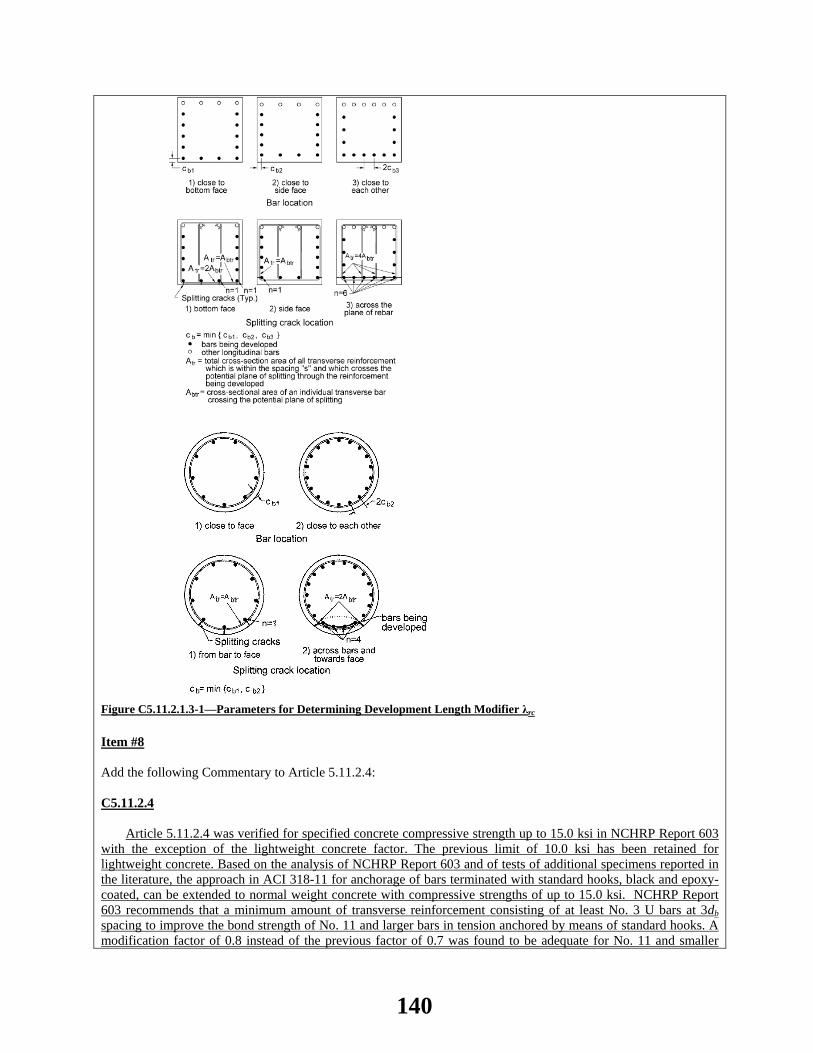
Figure C5.11.2.1.3-1—Parameters for Determining Development Length Modifier λrc
Item #8 Add the following Commentary to Article 5.11.2.4: C5.11.2.4
Article 5.11.2.4 was verified for specified concrete compressive strength up to 15.0 ksi in NCHRP Report 603 with the exception of the lightweight concrete factor. The previous limit of 10.0 ksi has been retained for lightweight concrete. Based on the analysis of NCHRP Report 603 and of tests of additional specimens reported in the literature, the approach in ACI 318-11 for anchorage of bars terminated with standard hooks, black and epoxy-coated, can be extended to normal weight concrete with compressive strengths of up to 15.0 ksi. NCHRP Report 603 recommends that a minimum amount of transverse reinforcement consisting of at least No. 3 U bars at 3db spacing to improve the bond strength of No. 11 and larger bars in tension anchored by means of standard hooks. A modification factor of 0.8 instead of the previous factor of 0.7 was found to be adequate for No. 11 and smaller
140

hooks with side cover not less than 2.5 in., and for 90 degree hooks with cover on bar extension beyond the hook not less than 2.0 in. Similar to the provisions of ACI 318-11, hooks are not considered effective in developing bars in compression. Item #9 Revise Article 5.11.2.4.1 as follows: 5.11.2.4.1—Basic Hook Development Length
The development length, ℓdh, in in., for deformed bars in tension terminating in a standard hook specified in Article 5.10.2.1 shall not be less thanbe determined as the basic development length, ℓhb, specified by Eq. 5.11.2.4.1-1 multiplied by the applicable modification factors specified in Article 5.11.2.4.2, but shall not be taken less than the smaller of: • The product of the basic development length, ℓhb, specified by Eq. 5.11.2.4.1-1, and the applicable
modification factor or factors, specified in Article 5.11.2.4.2;
• 8.0 bar diameters, and;or • 6.0 in.
Basic development length, ℓhb, for a hooked-bar with yield strength, fy, not exceeding 60.0 ksi shall be taken
as:
'0.38
fdlc
bhb = (5.11.2.4.1-1)
38.060.0 '
ybhb
c
fdf
=
(5.11.2.4.1-1)
where: db = diameter of bar or wire (in.) f’c = specified compressive strength of concrete for use in design at 28 days, unless another age is specified,
not to be taken greater than 15 ksi for normal weight concrete (ksi) fy = specified yield strength of reinforcing bars (ksi) Item #10
Revise Article 5.11.2.4.2 as follows:
5.11.2.4.2—Modification Factors
Basic hook development length, ℓhb, shall be multiplied by the following factor or factors, as applicable, where:
• Reinforcement has a yield strength exceeding 60.0 ksi……………. 60.0
yf
• Side cover for No. 11 bar and smaller, normal to plane of hook, is not less than 2.5 in., and 90o hook, cover on bar extension beyond hook not less than 2.0 in…………..0.7
141
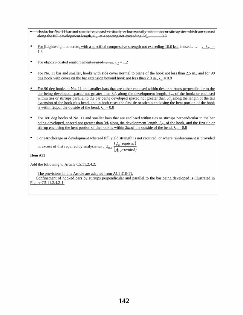
• Hooks for No. 11 bar and smaller enclosed vertically or horizontally within ties or stirrup ties which are spaced along the full development length, ℓdh, at a spacing not exceeding 3db…..……0.8
• For lLightweight concrete, with a specified compressive strength not exceeding 10.0 ksi, is used…… , λlw = 1.3
• For eEpoxy-coated reinforcement is used…….., λcf = 1.2 • For No. 11 bar and smaller, hooks with side cover normal to plane of the hook not less than 2.5 in., and for 90
deg hook with cover on the bar extension beyond hook not less than 2.0 in., λrc = 0.8 • For 90 deg hooks of No. 11 and smaller bars that are either enclosed within ties or stirrups perpendicular to the
bar being developed, spaced not greater than 3db along the development length, ℓdh, of the hook; or enclosed within ties or stirrups parallel to the bar being developed spaced not greater than 3db along the length of the tail extension of the hook plus bend, and in both cases the first tie or stirrup enclosing the bent portion of the hook is within 2db of the outside of the bend, λrc = 0.8
• For 180 deg hooks of No. 11 and smaller bars that are enclosed within ties or stirrups perpendicular to the bar
being developed, spaced not greater than 3db along the development length, ℓdh, of the hook, and the first tie or stirrup enclosing the bent portion of the hook is within 2db of the outside of the bend, λrc = 0.8
• For aAnchorage or development whereof full yield strength is not required, or where reinforcement is provided
in excess of that required by analysis….. , λer = ( )( )provided
required
AA
s
s
Item #11 Add the following to Article C5.11.2.4.2:
The provisions in this Article are adapted from ACI 318-11. Confinement of hooked bars by stirrups perpendicular and parallel to the bar being developed is illustrated in
Figure C5.11.2.4.2-1.
142

Figure C5.11.2.4.2-1—Confinement of Hooked Bars by Stirrups Item #12 In Article 5.11.2.5.1, revise the 3rd paragraph and replace Equations 1 and 2 as follows:
The basic development length, ℓhd, for welded deformed wire fabric, with not less than one cross wire within the development length at least 2.0 in. from the point of critical section, shall satisfy the larger of:
20.00.95 y
hd bc
f d
f
−≤
′
, or
20.0
0.95 yhd b
c
ffd
−≥
′
, and (5.11.2.5.1-1)
6.30'
w yhd
cw
A ffs
≥
(5.11.2.5.1-2)
Item #13 In Article 5.11.5.2.1, revise the 5th paragraph and replace Equation 5.11.5.2.1-1 as follows:
For columns with longitudinal reinforcing that anchors into oversized shafts, where bars are spliced by noncontact lap splices, and longitudinal column and shaft reinforcement are spaced farther apart transversely than one-fifth the required lap splice length or 6 in. as shown in Figure 5.11.5.2.1-1, the spacing of the shaft transverse reinforcement in the splice zone shall satisfy:
143
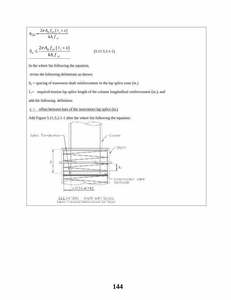
( )max
2 sh ytr s
u
A f sS
kA fπ +
=
( )2 sh ytr s
tru
A f sS
kA fπ +
≤
(5.11.5.2.1-1)
In the where list following the equation, revise the following definitions as shown: Str = spacing of transverse shaft reinforcement in the lap splice zone (in.) ℓs = required tension lap splice length of the column longitudinal reinforcement (in.), and add the following definition: s = offset between bars of the noncontact lap splice (in.) Add Figure 5.11.5.2.1-1 after the where list following the equation:
144
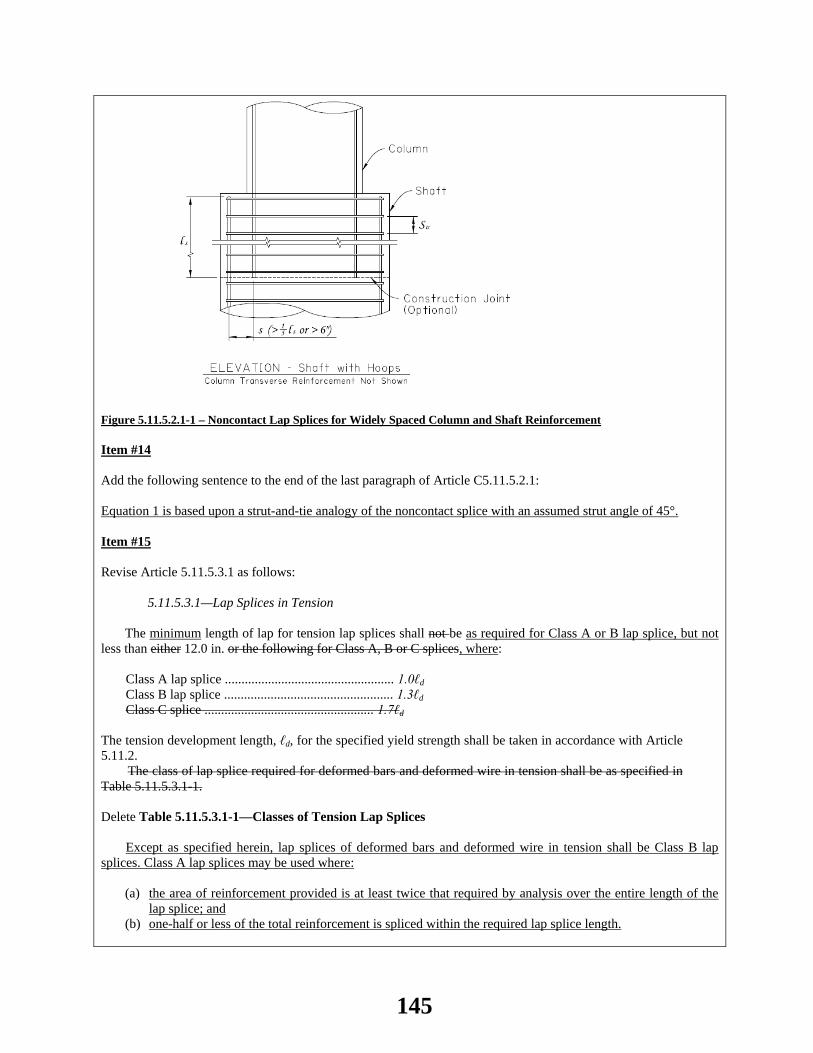
Figure 5.11.5.2.1-1 – Noncontact Lap Splices for Widely Spaced Column and Shaft Reinforcement Item #14 Add the following sentence to the end of the last paragraph of Article C5.11.5.2.1: Equation 1 is based upon a strut-and-tie analogy of the noncontact splice with an assumed strut angle of 45°. Item #15 Revise Article 5.11.5.3.1 as follows: 5.11.5.3.1—Lap Splices in Tension
The minimum length of lap for tension lap splices shall not be as required for Class A or B lap splice, but not less than either 12.0 in. or the following for Class A, B or C splices, where:
Class A lap splice ................................................... 1.0ℓd Class B lap splice ................................................... 1.3ℓd Class C splice ................................................... 1.7ℓd
The tension development length, ℓd, for the specified yield strength shall be taken in accordance with Article 5.11.2. The class of lap splice required for deformed bars and deformed wire in tension shall be as specified in Table 5.11.5.3.1-1.
Delete Table 5.11.5.3.1-1—Classes of Tension Lap Splices
Except as specified herein, lap splices of deformed bars and deformed wire in tension shall be Class B lap splices. Class A lap splices may be used where:
(a) the area of reinforcement provided is at least twice that required by analysis over the entire length of the
lap splice; and (b) one-half or less of the total reinforcement is spliced within the required lap splice length.
145

For lap splices having fy > 75.0 ksi, transverse reinforcement satisfying the requirements of Article 5.8.2.5 in beams and Article 5.10.6.3 in columns shall be provided over the required lap splice development length. Item #16 Add the following paragraph to the end of Article C5.11.5.3.1:
Tension lap splices were evaluated under NCHRP Report 603. Splices of bars in compression were not part of the experimental component of the research. Class C lap splices were eliminated based on the modifications to development length provisions. Item #17 Add the following to Article 5.15—References: ACI Committee 318. 2011. Building Code Requirements for Structural Concrete (ACI 318-11) and Commentary. ACI 318-11. American Concrete Institute, Farmington Hills, MI. Azizinamini, A., M. Stark, J. R. Roller, and S. K. Ghosh. 1993. “Bond Performance of Reinforcing Bars Embedded in Concrete,” ACI Structural Journal, Vol. 90, No. 5, September-October 1993, pp. 554-561. Darwin, D., L. Lutz, and J. Zuo. 2005. “Recommended Provisions and Commentary on Development and Lap Splice Lengths for Deformed Reinforcing bars in Tension,” ACI Structural Journal, Vol. 102, No. 6, Nov-Dec. 2005, pp. 892-900. Hosny, A., H. M. Seliem, S. H. Rizkalla, and P. Zia. 2012. “Development Length of Unconfined Conventional and High Strength Steel Reinforcing Bars, ACI Structural Journal, Vol. 109, No. 5, Sept-Oct. 2012, pp. 655-664.
OTHER AFFECTED ARTICLES:None
BACKGROUND:Article 5.4.2.1 limits the applicability of the specifications for concrete compressive strengths of 10 ksi or less unless physical tests are made to establish the relationships between concrete strength and other properties. A Ballot Item passed in 2012 (WAI 145A) extended the provision of Articles 5.11.2.1, 5.11.2.4, and 5.11.5.3.1 to 15.0 ksi. Also, the current provisions of the reinforcement development and splice length provisions are based on the ACI 318-89 Building Code, which has undergone considerable revisions up to the 2011 Edition. A comprehensive article-by-article review of Section 5 of these Specifications pertaining to transfer, development, and splice length for strand, reinforcing bars and reinforcing wire was performed under NCHRP Project 12-60, and described in Report 603. This review was conducted to identify all the provisions that directly or indirectly had to be revised to extend their use to specified concrete strengths up to 15 ksi. The proposed recommendations combine the recommendations of Report 603 on Transfer, Development, and Splice Length for Strand/Reinforcement in High Strength Concrete (Ramirez and Russell, 2008) and ACI 318-11 to include applications with specified concrete strengths up to 15 ksi. An extensive comparison among development lengths calculated by current AASHTO, ACI 318-11 and the proposed revisions is appended as Attachment A (provided on CD). The modifications to Article 5.11.2.1 in 2013 contain several changes that eliminated many of the concerns regarding tension lap splices due to closely spaced bars with minimal cover. However, the development lengths, on which lap splice lengths are based, have in some cases increased. Proper use of transverse reinforcement can yield
146
shorter lengths. A two-level lap splice length was retained primarily to encourage designers to splice bars at points of minimum stress and to stagger lap splices to improve behavior of critical details, but does not reflect the increased strength of the lap splice.
ANTICIPATED EFFECT ON BRIDGES:In general, ACI 318-11 is yielding longer development lengths than the ACI 318-89 Code. Experimental data supports the change.
REFERENCES: Ramirez, J. A., and B. W. Russell. 2008. “Transfer, Development, and Splice Length for Strand/ Reinforcement in High strength Concrete,” NCHRP Report 603. Transportation Research Board, National Research Council, Washington DC. ACI 318-11, Building Code Requirements for Reinforced Concrete, American Concrete Institute, Box 19150, Redford Station, Detroit, Michigan 48219. Hosny, A, Seliem HM, Rizkalla, SH, and Zia, P, “Development Length of Unconfined Conventional and High Strength Steel Reinforcing Bars,” NCHRP Report 603. Transportation Research Board, National Research Council, Washington DC. ACI Structural Journal, Vol. 109, No. 5, Sept-Oct. 2012, pp. 655-664. Darwin, D, Lutz, L, Zuo, J, “Recommended Provisions and Commentary on Development and Lap Splice Lengths for Deformed Reinforcing bars in Tension,” ACI Structural Journal, Vol.102, No. 6, Nov. Dec. 2005, pp. 892-900.
OTHER: None
147

2014 AASHTO BRIDGE COMMITTEE AGENDA ITEM: 34 SUBJECT: LRFD Bridge Design Specifications: Section 5, Various Articles (WAI 176) TECHNICAL COMMITTEE: T-10 Concrete
REVISION ADDITION NEW DOCUMENT
DESIGN SPEC CONSTRUCTION SPEC MOVABLE SPEC MANUAL FOR BRIDGE SEISMIC GUIDE SPEC BRIDGE ELEMENT INSP GUIDE
EVALUATION OTHER DATE PREPARED: 1/10/14 DATE REVISED: 4/29/14 AGENDA ITEM:Item #1 Add the following notation to Article 5.3: kc = factor for the effect of the volume-to-surface ratio; ratio of the maximum concrete compressive stress to the specified compressive strength of concrete (C5.4.2.3.2) (5.7.4.4) α1 = stress block factor taken as the ratio of equivalent rectangular concrete compressive stress block intensity to the specified compressive strength of concrete (5.7.2.2) Item #2 In Article 5.4.2.3.2, revise Eq. 5.4.2.3.2-5 as follows:
𝑘𝑡𝑑 = �𝑡
61 − 4𝑓𝑐𝑖′ + 𝑡�
𝑘𝑡𝑑 = 𝑡
12 �100 − 4𝑓𝑐𝑖′𝑓𝑐𝑖′ + 20 � + 𝑡
_______________________
(5.4.2.3.2-5)
Item #3 Revise the 1st paragraph of Article C5.4.2.3.2 as follows:
The methods of determining creep and shrinkage, as specified herein and in Article 5.4.2.3.3, are based on Huo et al. (2001), Al-Omaishi (2001), Tadros (2003), Rizkalla et al. (2007), and Collins and Mitchell (1991). These methods are based on the recommendation of ACI Committee 209 as modified by additional recently published data. Other applicable references include Rusch et al. (1983), Bazant and Wittman (1982), and Ghali and Favre (1986). Item #4 Revise the 1st paragraph and Eq. 5.4.2.4-1 of Article 5.4.2.4 as follows:
148

In the absence of measured data, the modulus of elasticity, Ec, for concretes with unit weights between 0.090 and
0.155 kcf and for normal weight concrete with specified compressive strengths up to 15.0 ksi may be taken as: 𝐸𝑐 = 33,000𝐾1𝑤𝑐1.5�𝑓𝑐′ 𝐸𝑐 = 120,000𝐾1𝑤𝑐2.0𝑓𝑐′0.33 (5.4.2.4-1) Item #5 Revise Eq. C5.4.2.4-1 and the last paragraph of Article C5.4.2.4 as follows: 𝐸𝑐 = 1,820�𝑓𝑐′ 𝐸𝑐 = 2,500𝑓𝑐′0.33 (C5.4.2.4-1) Eqs. 5.4.2.4-1 and C5.4.2.4-1 are based upon the research of Greene and Graybeal (2013).
For normal weight concrete with wc = 0.145 kcf and specified compressive strength up to10 ksi, Ec may be taken as: 𝐸𝑐 = 33,000𝐾1𝑤𝑐1.5�𝑓𝑐′ (C5.4.2.4-2) or 𝐸𝑐 = 1,820�𝑓𝑐′ (C5.4.2.4-3) Eqs. C5.4.2.4-2 and C5.4.2.4-3 are the traditional equations which do not fully reflect lightweight concrete and higher compressive strengths.
Test data show that the modulus of elasticity of concrete is influenced by the stiffness of the aggregate. The factor K1 is included to allow the calculated modulus to be adjusted for different types of aggregate and local materials. Unless a value has been determined by physical tests, K1 should be taken as 1.0. Use of a measured K1 factor permits a more accurate prediction of modulus of elasticity and other values that utilize it. Item #6 Revise Article 5.4.2.5 as follows: 5.4.2.5—Poisson’s Ratio
Unless determined by physical tests, Poisson’s ratio may be assumed as 0.2 for lightweight concrete with specified compressive strengths up to 10.0 ksi and for normal weight concrete with specified compressive strengths up to 15.0 ksi. For components expected to be subject to cracking, the effect of Poisson’s ratio may be neglected. Item #7
Add the following paragraph to Article 5.7.2:
5.7.2—Assumption for Strength and Extreme Events Limit States
The following assumptions may be used for normal weight concrete with specified compressive strengths up to 15.0 ksi. Item #8 Add the following paragraph to Article C5.7.2.1 opposite the 3rd bullet in Article 5.7.2.1 and before the existing
149

paragraph:
The results of Rizkalla et al. (2007) have shown that the maximum usable strain at the extreme concrete compression fiber of 0.003 is valid for flexural members with specified compressive strengths up to 18 ksi for normal weight concrete even though the provisions are currently limited to 15 ksi. Item #9 Revise the 1st paragraph of Article 5.7.2.2 as follows:
The natural relationship between concrete stress and strain may be considered satisfied by an equivalent rectangular concrete compressive stress block of 0.85 α1 fc
’ over a zone bounded by the edges of the cross-section and a straight line located parallel to the neutral axis at the distance a = β1 c from the extreme compression fiber. The distance c shall be measured perpendicular to the neutral axis. The factor α1 shall be taken as 0.85 for specified concrete compressive strengths not exceeding 10.0 ksi. For specified concrete compressive strengths exceeding 10.0 ksi, α1 shall be reduced at a rate of 0.02 for each 1.0 ksi of strength in excess of 10.0 ksi, except that α1 shall not be taken to be less than 0.75. The factor β1 shall be taken as 0.85 for concrete specified concrete compressive strengths not exceeding 4.0 ksi. For concrete specified concrete compressive strengths exceeding 4.0 ksi, β1 shall be reduced at a rate of 0.05 for each 1.0 ksi of strength in excess of 4.0 ksi, except that β1 shall not be taken to be less than 0.65. Item #10 Insert a new 2nd paragraph in Article C5.7.2.2:
Rizkalla et al. (2007) determined that α1 gradually decreases for specified concrete compressive strengths in excess of 10 ksi. Item #11 Add the following paragraph to Article 5.7.3: 5.7.3— Flexural Members
The following assumptions may be used for normal weight concrete with specified compressive strengths up to 15.0 ksi. Item #12 In Article 5.7.3.1.1, revise Eqs. 5.7.3.1.1-3 and 5.7.3.1.1-4 and add the following definition to the where list:
𝑐 =𝐴𝑝𝑠𝑓𝑝𝑢 + 𝐴𝑠𝑓𝑠−𝐴𝑠′ 𝑓𝑠′ − 0.85𝑓𝑐′(𝑏 − 𝑏𝑤)ℎ𝑓
0.85𝑓𝑐′β1𝑏𝑤 + 𝑘𝐴𝑝𝑠𝑓𝑝𝑢𝑑𝑝
𝑐 =𝐴𝑝𝑠𝑓𝑝𝑢 + 𝐴𝑠𝑓𝑠−𝐴𝑠′ 𝑓𝑠′ − α1𝑓𝑐′(𝑏 − 𝑏𝑤)ℎ𝑓
α1𝑓𝑐′β1𝑏𝑤 + 𝑘𝐴𝑝𝑠𝑓𝑝𝑢𝑑𝑝
______________________________________
(5.7.3.1.1-3)
𝑐 =𝐴𝑝𝑠𝑓𝑝𝑢 + 𝐴𝑠𝑓𝑠−𝐴𝑠′ 𝑓𝑠′
0.85𝑓𝑐′β1𝑏 + 𝑘𝐴𝑝𝑠𝑓𝑝𝑢𝑑𝑝
150
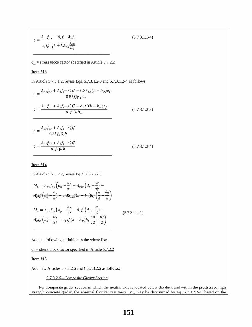
𝑐 =𝐴𝑝𝑠𝑓𝑝𝑢 + 𝐴𝑠𝑓𝑠−𝐴𝑠′ 𝑓𝑠′
α1𝑓𝑐′β1𝑏 + 𝑘𝐴𝑝𝑠𝑓𝑝𝑢𝑑𝑝
_____________________________________
(5.7.3.1.1-4)
α1 = stress block factor specified in Article 5.7.2.2 Item #13 In Article 5.7.3.1.2, revise Eqs. 5.7.3.1.2-3 and 5.7.3.1.2-4 as follows:
𝑐 =𝐴𝑝𝑠𝑓𝑝𝑠 + 𝐴𝑠𝑓𝑠−𝐴𝑠′ 𝑓𝑠′ − 0.85𝑓𝑐′(𝑏 − 𝑏𝑤)ℎ𝑓
0.85𝑓𝑐′β1𝑏𝑤
𝑐 =𝐴𝑝𝑠𝑓𝑝𝑠 + 𝐴𝑠𝑓𝑠−𝐴𝑠′ 𝑓𝑠′ − α1𝑓𝑐′(𝑏 − 𝑏𝑤)ℎ𝑓
α1𝑓𝑐′β1𝑏𝑤
______________________________________
(5.7.3.1.2-3)
𝑐 =𝐴𝑝𝑠𝑓𝑝𝑠 + 𝐴𝑠𝑓𝑠−𝐴𝑠′ 𝑓𝑠′
0.85𝑓𝑐′β1𝑏
𝑐 =𝐴𝑝𝑠𝑓𝑝𝑠 + 𝐴𝑠𝑓𝑠−𝐴𝑠′ 𝑓𝑠′
α1𝑓𝑐′β1𝑏
______________________________________
(5.7.3.1.2-4)
Item #14 In Article 5.7.3.2.2, revise Eq. 5.7.3.2.2-1.
𝑀𝑎 = 𝐴𝑝𝑠𝑓𝑝𝑠 �𝑑𝑝 −
𝑎2� + 𝐴𝑠𝑓𝑠 �𝑑𝑠 −
𝑎2� −
𝐴𝑠′ 𝑓𝑠′ �𝑑𝑠′ −𝑎2� + 0.851𝑓𝑐′(𝑏 − 𝑏𝑤)ℎ𝑓 �
𝑎2−ℎ𝑓2�
𝑀𝑎 = 𝐴𝑝𝑠𝑓𝑝𝑠 �𝑑𝑝 −𝑎2� + 𝐴𝑠𝑓𝑠 �𝑑𝑠 −
𝑎2� −
𝐴𝑠′ 𝑓𝑠′ �𝑑𝑠′ −𝑎2� + α1𝑓𝑐′(𝑏 − 𝑏𝑤)ℎ𝑓 �
𝑎2−ℎ𝑓2�
_____________________________________
(5.7.3.2.2-1)
Add the following definition to the where list: α1 = stress block factor specified in Article 5.7.2.2 Item #15 Add new Articles 5.7.3.2.6 and C5.7.3.2.6 as follows:
5.7.3.2.6—Composite Girder Section
For composite girder section in which the neutral axis is located below the deck and within the prestressed high strength concrete girder, the nominal flexural resistance, Mn, may be determined by Eq. 5.7.3.2.2-1, based on the
151
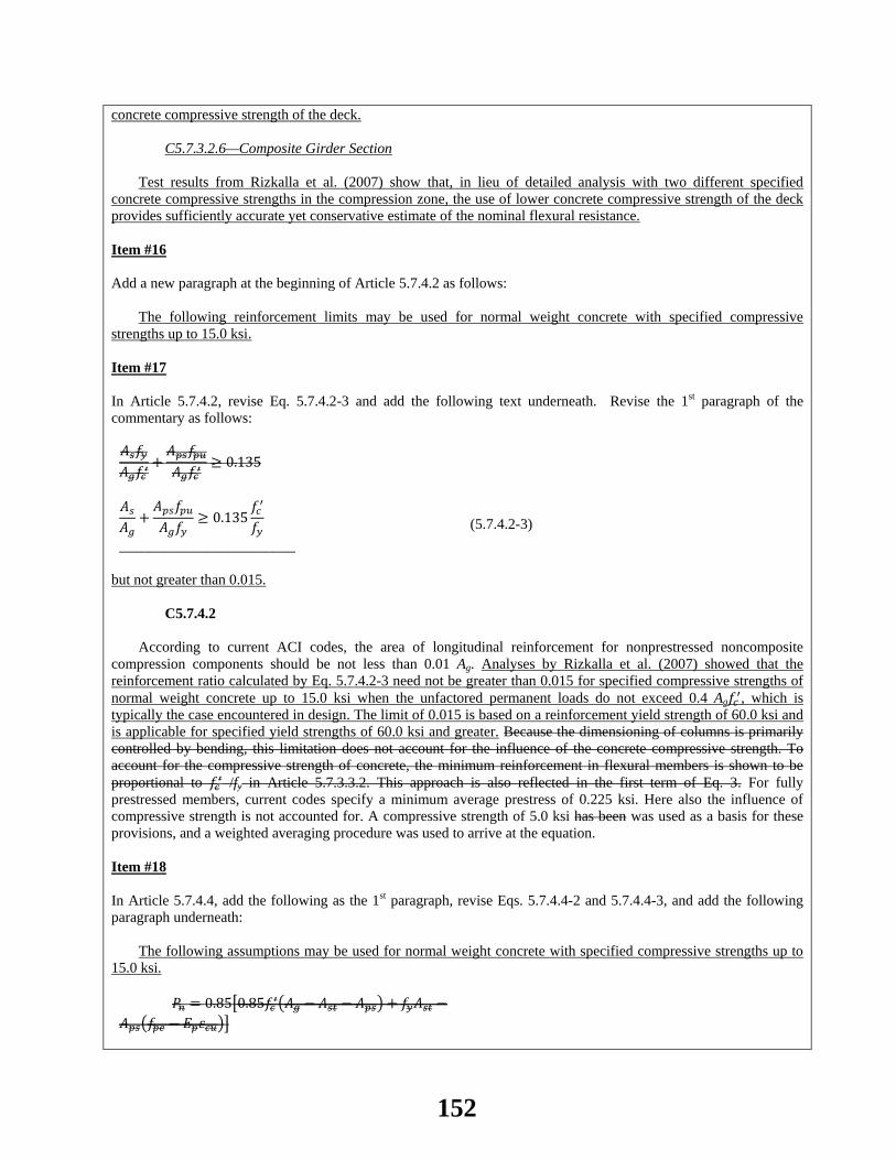
concrete compressive strength of the deck.
C5.7.3.2.6—Composite Girder Section
Test results from Rizkalla et al. (2007) show that, in lieu of detailed analysis with two different specified concrete compressive strengths in the compression zone, the use of lower concrete compressive strength of the deck provides sufficiently accurate yet conservative estimate of the nominal flexural resistance. Item #16 Add a new paragraph at the beginning of Article 5.7.4.2 as follows:
The following reinforcement limits may be used for normal weight concrete with specified compressive strengths up to 15.0 ksi.
Item #17 In Article 5.7.4.2, revise Eq. 5.7.4.2-3 and add the following text underneath. Revise the 1st paragraph of the commentary as follows: 𝐴𝑠𝑓𝑦𝐴𝑔𝑓𝑐′
+𝐴𝑝𝑠𝑓𝑝𝑢𝐴𝑔𝑓𝑐′
≥ 0.135
𝐴𝑠𝐴𝑔
+𝐴𝑝𝑠𝑓𝑝𝑢𝐴𝑔𝑓𝑦
≥ 0.135𝑓𝑐′
𝑓𝑦
________________________
(5.7.4.2-3)
but not greater than 0.015.
C5.7.4.2
According to current ACI codes, the area of longitudinal reinforcement for nonprestressed noncomposite compression components should be not less than 0.01 Ag. Analyses by Rizkalla et al. (2007) showed that the reinforcement ratio calculated by Eq. 5.7.4.2-3 need not be greater than 0.015 for specified compressive strengths of normal weight concrete up to 15.0 ksi when the unfactored permanent loads do not exceed 0.4 Ag𝑓𝑐′, which is typically the case encountered in design. The limit of 0.015 is based on a reinforcement yield strength of 60.0 ksi and is applicable for specified yield strengths of 60.0 ksi and greater. Because the dimensioning of columns is primarily controlled by bending, this limitation does not account for the influence of the concrete compressive strength. To account for the compressive strength of concrete, the minimum reinforcement in flexural members is shown to be proportional to 𝑓𝑐′ /fy in Article 5.7.3.3.2. This approach is also reflected in the first term of Eq. 3. For fully prestressed members, current codes specify a minimum average prestress of 0.225 ksi. Here also the influence of compressive strength is not accounted for. A compressive strength of 5.0 ksi has been was used as a basis for these provisions, and a weighted averaging procedure was used to arrive at the equation. Item #18 In Article 5.7.4.4, add the following as the 1st paragraph, revise Eqs. 5.7.4.4-2 and 5.7.4.4-3, and add the following paragraph underneath:
The following assumptions may be used for normal weight concrete with specified compressive strengths up to 15.0 ksi.
𝑃𝑛 = 0.85�0.85𝑓𝑐′�𝐴𝑔 − 𝐴𝑠𝑡 − 𝐴𝑝𝑠� + 𝑓𝑦𝐴𝑠𝑡 −𝐴𝑝𝑠�𝑓𝑝𝑒 − 𝐸𝑝𝜀𝑐𝑢��
152
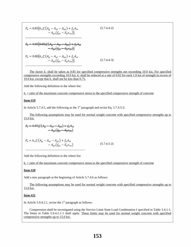
𝑃𝑛 = 0.85�𝑘𝑐𝑓𝑐′�𝐴𝑔 − 𝐴𝑠𝑡 − 𝐴𝑝𝑠� + 𝑓𝑦𝐴𝑠𝑡
− 𝐴𝑝𝑠�𝑓𝑝𝑒 − 𝐸𝑝ε𝑐𝑢�� ____________________________________
(5.7.4.4-2)
𝑃𝑛 = 0.80�0.85𝑓𝑐′�𝐴𝑔 − 𝐴𝑠𝑡 − 𝐴𝑝𝑠� + 𝑓𝑦𝐴𝑠𝑡
− 𝐴𝑝𝑠�𝑓𝑝𝑒 − 𝐸𝑝𝜀𝑐𝑢�� 𝑃𝑛 = 0.80�𝑘𝑐𝑓𝑐′�𝐴𝑔 − 𝐴𝑠𝑡 − 𝐴𝑝𝑠� + 𝑓𝑦𝐴𝑠𝑡
− 𝐴𝑝𝑠�𝑓𝑝𝑒 − 𝐸𝑝ε𝑐𝑢�� ____________________________________
(5.7.4.4-3)
The factor kc shall be taken as 0.85 for specified compressive strengths not exceeding 10.0 ksi, For specified
compressive strengths exceeding 10.0 ksi, kc shall be reduced at a rate of 0.02 for each 1.0 ksi of strength in excess of 10.0 ksi, except that kc shall not be less than 0.75. Add the following definition to the where list: kc = ratio of the maximum concrete compressive stress to the specified compressive strength of concrete Item #19 In Article 5.7.4.5, add the following as the 1st paragraph and revise Eq. 5.7.4.5-2:
The following assumptions may be used for normal weight concrete with specified compressive strengths up to 15.0 ksi. 𝑃𝑜 = 0.85𝑓𝑐′�𝐴𝑔 − 𝐴𝑠𝑡 − 𝐴𝑝𝑠� + 𝑓𝑦𝐴𝑠𝑡
− 𝐴𝑝𝑠�𝑓𝑝𝑐 − 𝐸𝑝𝜀𝑐𝑢�
𝑃𝑜 = 𝑘𝑐𝑓𝑐′�𝐴𝑔 − 𝐴𝑠𝑡 − 𝐴𝑝𝑠� + 𝑓𝑦𝐴𝑠𝑡− 𝐴𝑝𝑠�𝑓𝑝𝑐 − 𝐸𝑝𝜀𝑐𝑢�
______________________________________
(5.7.4.5-2)
Add the following definition to the where list: kc = ratio of the maximum concrete compressive stress to the specified compressive strength of concrete Item #20 Add a new paragraph at the beginning of Article 5.7.4.6 as follows:
The following assumptions may be used for normal weight concrete with specified compressive strengths up to 15.0 ksi. Item #21 In Article 5.9.4.2.1, revise the 1st paragraph as follows:
Compression shall be investigated using the Service Limit State Load Combination I specified in Table 3.4.1-1.
The limits in Table 5.9.4.2.1-1 shall apply. These limits may be used for normal weight concrete with specified compressive strengths up to 15.0 ksi.
153
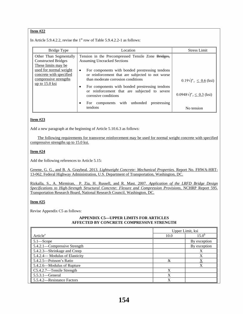
Item #22 In Article 5.9.4.2.2, revise the 1st row of Table 5.9.4.2.2-1 as follows:
Bridge Type Location Stress Limit Other Than Segmentally Constructed Bridges These limits may be used for normal weight concrete with specified compressive strengths up to 15.0 ksi
Tension in the Precompressed Tensile Zone Bridges, Assuming Uncracked Sections
• For components with bonded prestressing tendons
or reinforcement that are subjected to not worse than moderate corrosion conditions
• For components with bonded prestressing tendons or reinforcement that are subjected to severe corrosive conditions
• For components with unbonded prestressing tendons
0.19√ f ′c ≤ 0.6 (ksi)
0.0948√ f ′c ≤ 0.3 (ksi)
No tension
Item #23 Add a new paragraph at the beginning of Article 5.10.6.3 as follows:
The following requirements for transverse reinforcement may be used for normal weight concrete with specified compressive strengths up to 15.0 ksi. Item #24 Add the following references to Article 5.15: Greene, G. G., and B. A. Graybeal. 2013. Lightweight Concrete: Mechanical Properties. Report No. FHWA-HRT-13-062, Federal Highway Administration, U.S. Department of Transportation, Washington, DC. Rizkalla, S., A. Mirmiran, P. Zia, H. Russell, and R. Mast. 2007. Application of the LRFD Bridge Design Specifications to High-Strength Structural Concrete: Flexure and Compression Provisions, NCHRP Report 595. Transportation Research Board, National Research Council, Washington, DC.
Item #25 Revise Appendix C5 as follows:
APPENDIX C5—UPPER LIMITS FOR ARTICLES AFFECTED BY CONCRETE COMPRESSIVE STRENGTH
Articlea Upper Limit, ksi
10.0 15.0b 5.1—Scope By exception 5.4.2.1—Compressive Strength By exception 5.4.2.3—Shrinkage and Creep X 5.4.2.4— Modulus of Elasticity X 5.4.2.5—Poisson’s Ratio X X 5.4.2.6—Modulus of Rupture X C5.4.2.7—Tensile Strength X 5.5.3.1—General X 5.5.4.2—Resistance Factors X
154
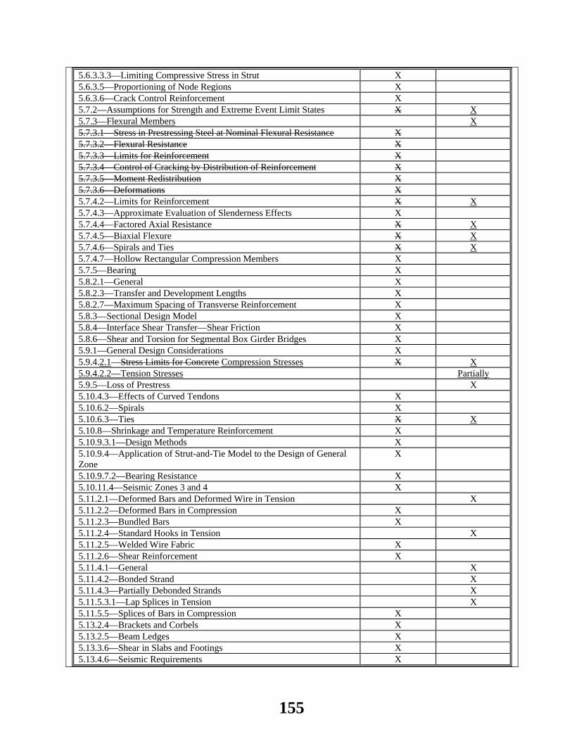
5.6.3.3.3—Limiting Compressive Stress in Strut X 5.6.3.5—Proportioning of Node Regions X 5.6.3.6—Crack Control Reinforcement X 5.7.2—Assumptions for Strength and Extreme Event Limit States X X 5.7.3—Flexural Members X 5.7.3.1—Stress in Prestressing Steel at Nominal Flexural Resistance X 5.7.3.2—Flexural Resistance X 5.7.3.3—Limits for Reinforcement X 5.7.3.4—Control of Cracking by Distribution of Reinforcement X 5.7.3.5—Moment Redistribution X 5.7.3.6—Deformations X 5.7.4.2—Limits for Reinforcement X X 5.7.4.3—Approximate Evaluation of Slenderness Effects X 5.7.4.4—Factored Axial Resistance X X 5.7.4.5—Biaxial Flexure X X 5.7.4.6—Spirals and Ties X X 5.7.4.7—Hollow Rectangular Compression Members X 5.7.5—Bearing X 5.8.2.1—General X 5.8.2.3—Transfer and Development Lengths X 5.8.2.7—Maximum Spacing of Transverse Reinforcement X 5.8.3—Sectional Design Model X 5.8.4—Interface Shear Transfer—Shear Friction X 5.8.6—Shear and Torsion for Segmental Box Girder Bridges X 5.9.1—General Design Considerations X 5.9.4.2.1—Stress Limits for Concrete Compression Stresses X X 5.9.4.2.2—Tension Stresses Partially 5.9.5—Loss of Prestress X 5.10.4.3—Effects of Curved Tendons X 5.10.6.2—Spirals X 5.10.6.3—Ties X X 5.10.8—Shrinkage and Temperature Reinforcement X 5.10.9.3.1—Design Methods X 5.10.9.4—Application of Strut-and-Tie Model to the Design of General Zone
X
5.10.9.7.2—Bearing Resistance X 5.10.11.4—Seismic Zones 3 and 4 X 5.11.2.1—Deformed Bars and Deformed Wire in Tension X 5.11.2.2—Deformed Bars in Compression X 5.11.2.3—Bundled Bars X 5.11.2.4—Standard Hooks in Tension X 5.11.2.5—Welded Wire Fabric X 5.11.2.6—Shear Reinforcement X 5.11.4.1—General X 5.11.4.2—Bonded Strand X 5.11.4.3—Partially Debonded Strands X 5.11.5.3.1—Lap Splices in Tension X 5.11.5.5—Splices of Bars in Compression X 5.13.2.4—Brackets and Corbels X 5.13.2.5—Beam Ledges X 5.13.3.6—Shear in Slabs and Footings X 5.13.4.6—Seismic Requirements X
155
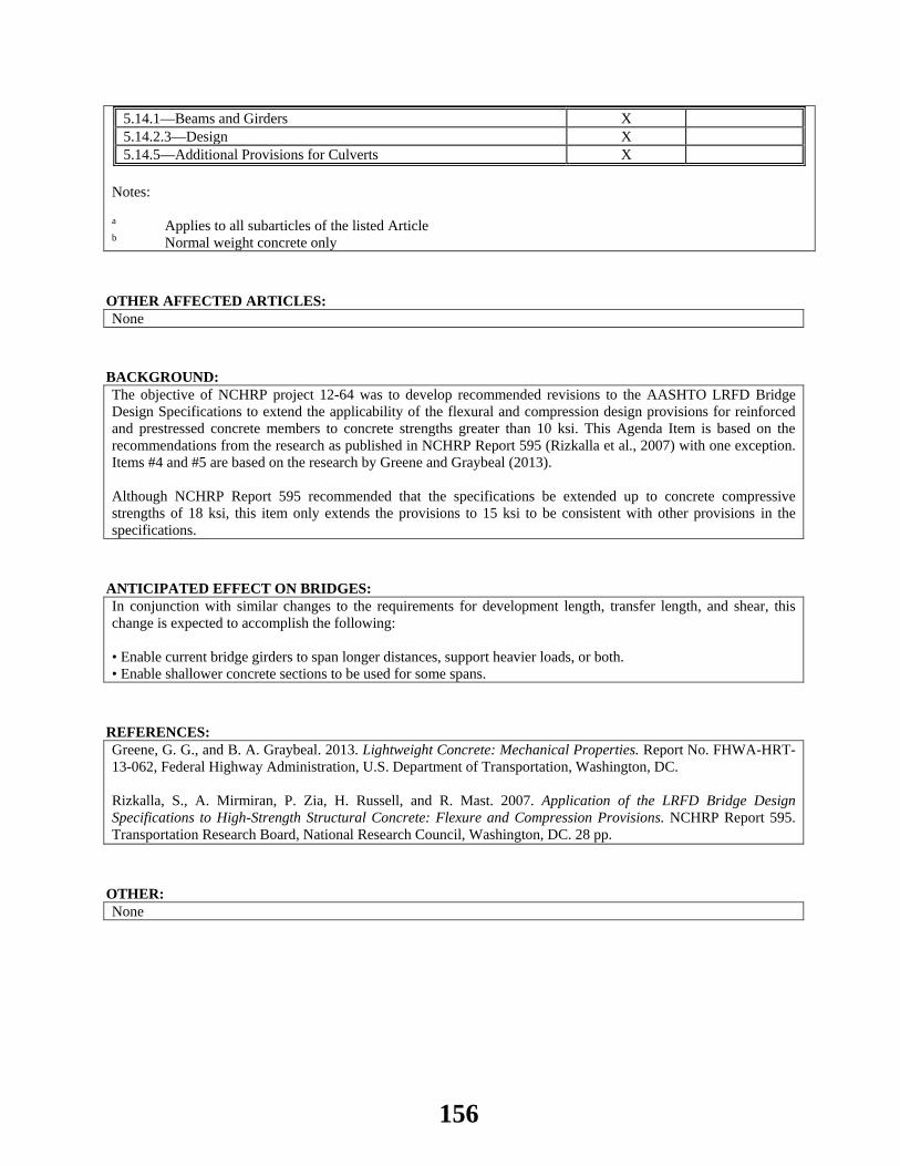
5.14.1—Beams and Girders X 5.14.2.3—Design X 5.14.5—Additional Provisions for Culverts X
Notes: a Applies to all subarticles of the listed Article b Normal weight concrete only
OTHER AFFECTED ARTICLES:None
BACKGROUND:The objective of NCHRP project 12-64 was to develop recommended revisions to the AASHTO LRFD Bridge Design Specifications to extend the applicability of the flexural and compression design provisions for reinforced and prestressed concrete members to concrete strengths greater than 10 ksi. This Agenda Item is based on the recommendations from the research as published in NCHRP Report 595 (Rizkalla et al., 2007) with one exception. Items #4 and #5 are based on the research by Greene and Graybeal (2013). Although NCHRP Report 595 recommended that the specifications be extended up to concrete compressive strengths of 18 ksi, this item only extends the provisions to 15 ksi to be consistent with other provisions in the specifications.
ANTICIPATED EFFECT ON BRIDGES:In conjunction with similar changes to the requirements for development length, transfer length, and shear, this change is expected to accomplish the following: • Enable current bridge girders to span longer distances, support heavier loads, or both. • Enable shallower concrete sections to be used for some spans.
REFERENCES: Greene, G. G., and B. A. Graybeal. 2013. Lightweight Concrete: Mechanical Properties. Report No. FHWA-HRT-13-062, Federal Highway Administration, U.S. Department of Transportation, Washington, DC. Rizkalla, S., A. Mirmiran, P. Zia, H. Russell, and R. Mast. 2007. Application of the LRFD Bridge Design Specifications to High-Strength Structural Concrete: Flexure and Compression Provisions. NCHRP Report 595. Transportation Research Board, National Research Council, Washington, DC. 28 pp.
OTHER: None
156
2014 AASHTO BRIDGE COMMITTEE AGENDA ITEM: 35 SUBJECT: LRFD Bridge Design Specifications: Section 5, Articles 5.8.3.1, C5.8.3.1, 5.15 & Appendix C5 (WAI 177) TECHNICAL COMMITTEE: T-10 Concrete
REVISION ADDITION NEW DOCUMENT
DESIGN SPEC CONSTRUCTION SPEC MOVABLE SPEC MANUAL FOR BRIDGE SEISMIC GUIDE SPEC BRIDGE ELEMENT INSP GUIDE
EVALUATION OTHER DATE PREPARED: 9/28/10 DATE REVISED: 4/9/14 AGENDA ITEM:
Item #1 Add the following to the 1st paragraph in Article 5.8.3.1:
The sectional design model may be used for shear design where permitted in accordance with the provisions of Article 5.8.1. The provisions of Article 5.8.3 may be used for normal weight concrete with specified compressive strengths up to 15.0 ksi. Item #2 Add a 2nd paragraph to Article C5.8.3.1 as follows:
The extension of these shear provisions to normal weight concretes with compressive strengths up to 15.0 ksi is based on the work presented in NCHRP Report 579 (Hawkins and Kuchma, 2007 and Kuchma et al., 2008).
Item #3 Revise and add the following references in Article 5.15: Hawkins, N. M., and D. A. Kuchma., R. F. Mast, M. L. Marsh, and K. H. Reineck. 2005 2006. Simplified Shear Design of Structural Concrete Members, NCHRP Report 549XX1. Transportation Research Board, National Research Council, Washington, DC. Hawkins, N. M., and D. A. Kuchma., H. G. Russell, G. J. Klein, and N. S. Anderson. 2006 2007. Application of the LRFD Bridge Design Specifications to High-Strength Structural Concrete: Shear Provisions, NCHRP Report 579XX2. Transportation Research Board, National Research Council, Washington, DC. Kuchma, D. A., K. S. Kim, T. J. Nagle, S. Sun, and N. M. Hawkins. 2008. “Shear Tests on High-Strength Prestressed Bulb-Tee Girders: Strengths and Key Observations”, ACI Structural Journal, American Concrete Institute, Farmington Hills, MI. Vol. 105, No. 3, May-June 2008, pp. 358-367. Item #4 Revise Appendix C5 as follows:
157
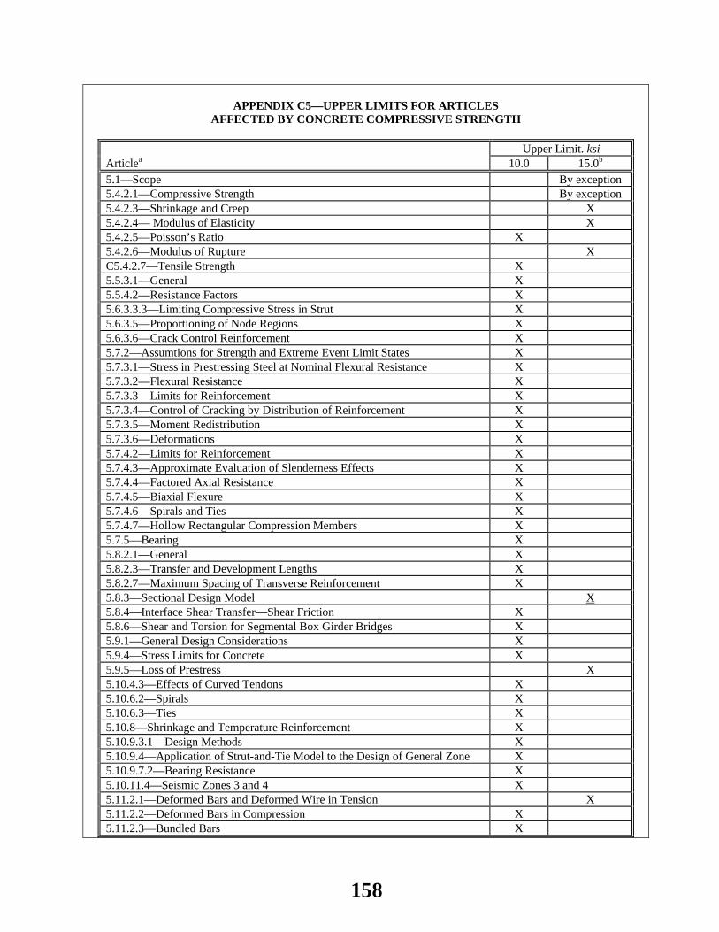
APPENDIX C5—UPPER LIMITS FOR ARTICLES
AFFECTED BY CONCRETE COMPRESSIVE STRENGTH
Articlea Upper Limit. ksi
10.0 15.0b
5.1—Scope By exception 5.4.2.1—Compressive Strength By exception 5.4.2.3—Shrinkage and Creep X 5.4.2.4— Modulus of Elasticity X 5.4.2.5—Poisson’s Ratio X 5.4.2.6—Modulus of Rupture X C5.4.2.7—Tensile Strength X 5.5.3.1—General X 5.5.4.2—Resistance Factors X 5.6.3.3.3—Limiting Compressive Stress in Strut X 5.6.3.5—Proportioning of Node Regions X 5.6.3.6—Crack Control Reinforcement X 5.7.2—Assumtions for Strength and Extreme Event Limit States X 5.7.3.1—Stress in Prestressing Steel at Nominal Flexural Resistance X 5.7.3.2—Flexural Resistance X 5.7.3.3—Limits for Reinforcement X 5.7.3.4—Control of Cracking by Distribution of Reinforcement X 5.7.3.5—Moment Redistribution X 5.7.3.6—Deformations X 5.7.4.2—Limits for Reinforcement X 5.7.4.3—Approximate Evaluation of Slenderness Effects X 5.7.4.4—Factored Axial Resistance X 5.7.4.5—Biaxial Flexure X 5.7.4.6—Spirals and Ties X 5.7.4.7—Hollow Rectangular Compression Members X 5.7.5—Bearing X 5.8.2.1—General X 5.8.2.3—Transfer and Development Lengths X 5.8.2.7—Maximum Spacing of Transverse Reinforcement X 5.8.3—Sectional Design Model X 5.8.4—Interface Shear Transfer—Shear Friction X 5.8.6—Shear and Torsion for Segmental Box Girder Bridges X 5.9.1—General Design Considerations X 5.9.4—Stress Limits for Concrete X 5.9.5—Loss of Prestress X 5.10.4.3—Effects of Curved Tendons X 5.10.6.2—Spirals X 5.10.6.3—Ties X 5.10.8—Shrinkage and Temperature Reinforcement X 5.10.9.3.1—Design Methods X 5.10.9.4—Application of Strut-and-Tie Model to the Design of General Zone X 5.10.9.7.2—Bearing Resistance X 5.10.11.4—Seismic Zones 3 and 4 X 5.11.2.1—Deformed Bars and Deformed Wire in Tension X 5.11.2.2—Deformed Bars in Compression X 5.11.2.3—Bundled Bars X
158
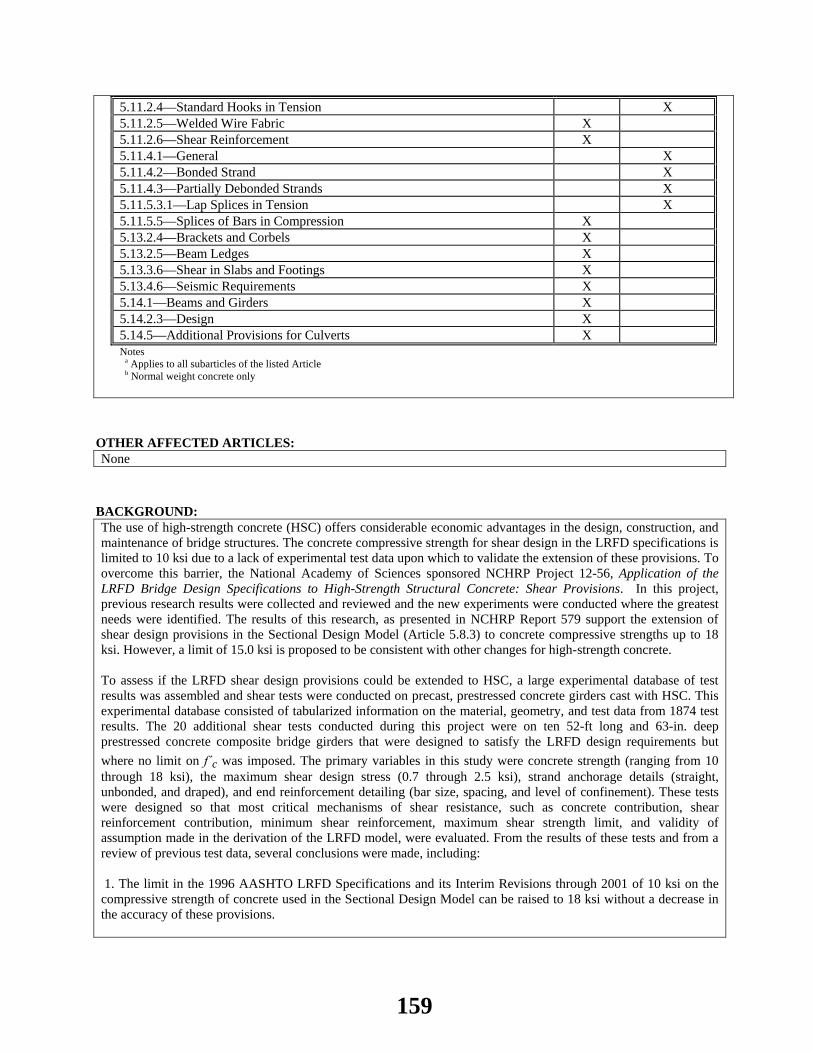
5.11.2.4—Standard Hooks in Tension X 5.11.2.5—Welded Wire Fabric X 5.11.2.6—Shear Reinforcement X 5.11.4.1—General X 5.11.4.2—Bonded Strand X 5.11.4.3—Partially Debonded Strands X 5.11.5.3.1—Lap Splices in Tension X 5.11.5.5—Splices of Bars in Compression X 5.13.2.4—Brackets and Corbels X 5.13.2.5—Beam Ledges X 5.13.3.6—Shear in Slabs and Footings X 5.13.4.6—Seismic Requirements X 5.14.1—Beams and Girders X 5.14.2.3—Design X 5.14.5—Additional Provisions for Culverts X Notes
a Applies to all subarticles of the listed Article b Normal weight concrete only
OTHER AFFECTED ARTICLES:None
BACKGROUND:The use of high-strength concrete (HSC) offers considerable economic advantages in the design, construction, and maintenance of bridge structures. The concrete compressive strength for shear design in the LRFD specifications is limited to 10 ksi due to a lack of experimental test data upon which to validate the extension of these provisions. To overcome this barrier, the National Academy of Sciences sponsored NCHRP Project 12-56, Application of the LRFD Bridge Design Specifications to High-Strength Structural Concrete: Shear Provisions. In this project, previous research results were collected and reviewed and the new experiments were conducted where the greatest needs were identified. The results of this research, as presented in NCHRP Report 579 support the extension of shear design provisions in the Sectional Design Model (Article 5.8.3) to concrete compressive strengths up to 18 ksi. However, a limit of 15.0 ksi is proposed to be consistent with other changes for high-strength concrete. To assess if the LRFD shear design provisions could be extended to HSC, a large experimental database of test results was assembled and shear tests were conducted on precast, prestressed concrete girders cast with HSC. This experimental database consisted of tabularized information on the material, geometry, and test data from 1874 test results. The 20 additional shear tests conducted during this project were on ten 52-ft long and 63-in. deep prestressed concrete composite bridge girders that were designed to satisfy the LRFD design requirements but where no limit on f΄c was imposed. The primary variables in this study were concrete strength (ranging from 10 through 18 ksi), the maximum shear design stress (0.7 through 2.5 ksi), strand anchorage details (straight, unbonded, and draped), and end reinforcement detailing (bar size, spacing, and level of confinement). These tests were designed so that most critical mechanisms of shear resistance, such as concrete contribution, shear reinforcement contribution, minimum shear reinforcement, maximum shear strength limit, and validity of assumption made in the derivation of the LRFD model, were evaluated. From the results of these tests and from a review of previous test data, several conclusions were made, including: 1. The limit in the 1996 AASHTO LRFD Specifications and its Interim Revisions through 2001 of 10 ksi on the compressive strength of concrete used in the Sectional Design Model can be raised to 18 ksi without a decrease in the accuracy of these provisions.
159

2. The LRFD Sectional Design Model, with an f´c limit of 18 ksi, is reasonably accurate and conservative except when designing for very high shear design stresses of vu > 0.18 f΄c in the end regions. This exception was already addressed by the following addition to Article 5.8.3.2: “If the shear stress at the design section calculated in accordance with Article 5.8.2.9 exceeds 0.18 f´c and the beam-type element is not built integrally with the support, its end region shall be designed using the strut-and-tie model specified in Article 5.6.3.” 3. The shear design provisions in the AASHTO Standard Specifications, the 2004 Canadian Standards Specifications, and the recommended simplified shear specifications of Article 5.8.3.4 provide similarly conservative estimates of shear capacity of test beams. 4. Designing members for shear stresses in excess of vu = 0.15 f´c can result in shear cracking and localized stirrup yielding under service load levels.
ANTICIPATED EFFECT ON BRIDGES:In conjunctions with similar changes to the requirements for flexure, compression, and development of reinforcement, this change is expected to accomplish the following: • Enable current bridge sections to span longer distances, support heavier loads, or both. • Enable a shallow section to be used for a span that permits a concrete solution to be used whereas before only a steel section would have worked. • Enable a section to be designed to not crack in shear under service load levels that would otherwise have been calculated to have cracked in shear.
REFERENCES: Hawkins, N. M. and D. A. Kuchma. 2006. Simplified Shear Design of Structural Concrete Members, NCHRP Report 549. Transportation Research Board, National Research Council, Washington, DC. Available online at http://onlinepubs.trb.org/onlinepubs/nchrp/nchrp_w78.pdf. Hawkins, N. M. and D. A. Kuchma. 2007. Application of LRFD Bridge Design Specifications to High- Strength Structural Concrete: Shear Provisions, NCHRP Report 579, Transportation Research Board, National Research Council, Washington, DC. Kuchma, D. A., K. S. Kim, T. J. Nagle, S. Sun, and N. M. Hawkins. 2008. “Shear Tests on High-Strength Prestressed Bulb-Tee Girders: Strengths and Key Observations”, ACI Structural Journal, American Concrete Institute, Farmington Hills, MI. Vol. 105, No. 3, May-June 2008, pp. 358-367.
OTHER: None
160

2014 AASHTO BRIDGE COMMITTEE AGENDA ITEM: 36 SUBJECT: LRFD Bridge Design Specifications: Section 5, Various Articles (WAI 178) TECHNICAL COMMITTEE: T-10 Concrete
REVISION ADDITION NEW DOCUMENT
DESIGN SPEC CONSTRUCTION SPEC MOVABLE SPEC MANUAL FOR BRIDGE SEISMIC GUIDE SPEC BRIDGE ELEMENT INSP GUIDE
EVALUATION OTHER DATE PREPARED: 1/15/14 DATE REVISED: 4/9/14 AGENDA ITEM:Item #1 Delete Article C5.4.1 as follows: C5.4.1
According to AASHTO LRFD Bridge Construction Specifications, all materials and tests must conform to the
appropriate standards included in the AASHTO Standard Specifications for Transportation Materials and Methods of Sampling and Testing and/or the standards of the American Society for Testing and Materials.
Occasionally, it may be appropriate to use materials other than those included in the AASHTO LRFD Bridge Construction Specifications; for example, when concretes are modified to obtain very high-strengths through the introduction of special materials, such as:
• Silica fume, • Cements other than Portland or blended hydraulic cements, • Proprietary high early strength cements, • Ground granulated blast-furnace slag, and • Other types of cementitious and/or Pozzolanic materials.
In these cases, the specified properties of such materials should be measured using the testing procedures defined in the contract documents. Item #2 Revise Article C5.4.2.3.3 as follows:
C5.4.2.3.3
Shrinkage of concrete can vary over a wide range from nearly nil if continually immersed in water to in excess of 0.0008 for thin sections made with high shrinkage aggregates and sections that are not properly cured.
Shrinkage is affected by:
• Aggregate characteristics and proportions, • Average humidity at the bridge site, • W/C ratio,
161
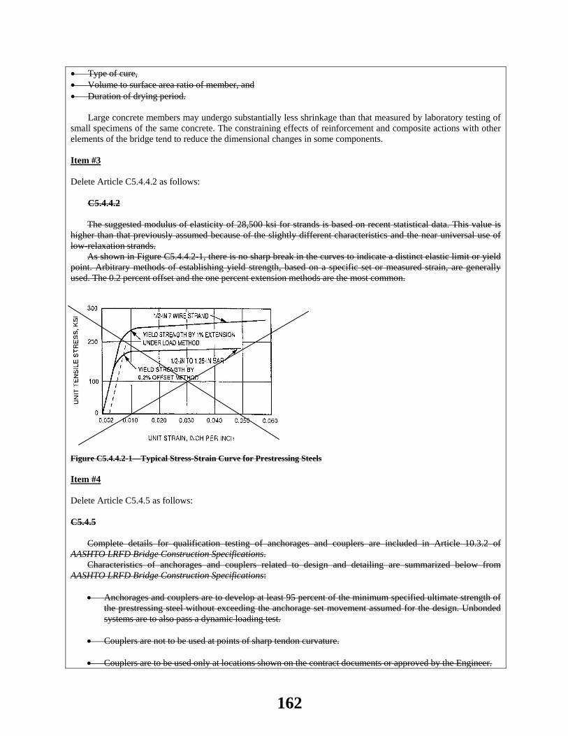
• Type of cure, • Volume to surface area ratio of member, and • Duration of drying period.
Large concrete members may undergo substantially less shrinkage than that measured by laboratory testing of small specimens of the same concrete. The constraining effects of reinforcement and composite actions with other elements of the bridge tend to reduce the dimensional changes in some components. Item #3 Delete Article C5.4.4.2 as follows:
C5.4.4.2 The suggested modulus of elasticity of 28,500 ksi for strands is based on recent statistical data. This value is
higher than that previously assumed because of the slightly different characteristics and the near universal use of low-relaxation strands.
As shown in Figure C5.4.4.2-1, there is no sharp break in the curves to indicate a distinct elastic limit or yield point. Arbitrary methods of establishing yield strength, based on a specific set or measured strain, are generally used. The 0.2 percent offset and the one percent extension methods are the most common.
Figure C5.4.4.2-1—Typical Stress-Strain Curve for Prestressing Steels Item #4 Delete Article C5.4.5 as follows: C5.4.5
Complete details for qualification testing of anchorages and couplers are included in Article 10.3.2 of
AASHTO LRFD Bridge Construction Specifications. Characteristics of anchorages and couplers related to design and detailing are summarized below from
AASHTO LRFD Bridge Construction Specifications:
• Anchorages and couplers are to develop at least 95 percent of the minimum specified ultimate strength of the prestressing steel without exceeding the anchorage set movement assumed for the design. Unbonded systems are to also pass a dynamic loading test.
• Couplers are not to be used at points of sharp tendon curvature.
• Couplers are to be used only at locations shown on the contract documents or approved by the Engineer.
162
• Couplers are to be enclosed in housings long enough to permit the necessary movements.
• Where bonded anchorages or couplers are located at sections that are critical at strength limit state, the
strength required of the bonded tendons is not to exceed the resistance of the tendon assembly, including the anchorage or coupler, tested in an unbonded state.
• Bearing stresses on concrete under anchorage distribution plates are not to exceed specified limits.
• Unless waived by the Engineer because of suitable previous tests and/or experience, qualification of anchorages and couplers are to be verified by testing.
Item #5 Revise Article C5.4.6.1 as follows:
The use of polyethylene duct is generally recommended in corrosive environments. Pertinent requirements for ducts can be found in Article 10.8.2 in AASHTO LRFD Bridge Construction Specifications.
Polyethylene duct should not be used on radii under 30.0 ft because of its lower resistance to abrasion during pulling-through and stressing tendons.
The contract documents should indicate the specific type of duct material to be used when only one type is to be allowed. Item #6 Delete Article C5.4.6.2 as follows:
C5.4.6.2 The pull-through method of tendon placement is usually employed by contractors where tendons exceed 400 ft
in length.
Item #7 Delete the second paragraph of Article C5.5.3.2 as follows:
Bends in primary reinforcement should be avoided in regions of high stress range. Item #8 Delete Article C5.6.1 as follows: C5.6.1
This Article reflects the AASHTO Standard Specifications for Highway Bridges (1996), the AASHTO Guide
Specifications for Design and Construction of Segmental Concrete Bridges (1989) and the Ontario Highway Bridge Design Code (1991). Item #9 Revise Article C.5.6.3.1 as follows:
Where the conventional methods of strength of materials are not applicable because of nonlinear strain
distribution, the strut-and-tie modeling may provide a convenient way of approximating load paths and force effects in the structure. In fact, the load paths may be visualized and the geometry of concrete and steel selected to implement the load path. More detailed information on this method is given by Schlaich et al. (1987) and Collins
163

and Mitchell (1991). The strut-and-tie model is new to these Specifications. More detailed information on this method is given by
Schlaich et al. (1987) and Collins and Mitchell (1991). Traditional section-by-section design is based on the assumption that the reinforcement required at a particular
section depends only on the separated values of the factored section force effects Vu, Mu, and Tu and does not consider the mechanical interaction among these force effects as the strut-and-tie model does. The traditional method further assumes that shear distribution remains uniform and that the longitudinal strains will vary linearly over the depth of the beam.
For members such as the deep beam shown in Figure C5.6.3.2-1, these assumptions are not valid. The shear stresses on a section just to the right of a support will be concentrated near the bottom face. The behavior of a component, such as the deep beam, can be predicted more accurately if the flow of forces through the complete structure is studied. Instead of determining Vu and Mu at different sections along the span, the flow of compressive stresses going from the loads P to the supports and the required tension force to be developed between the supports should be established.
For additional applications of the strut-and-tie model see Articles 5.10.9.4, 5.13.2.3, and 5.13.2.4.1
Item #10 Delete Article C5.7.3.2.2 as follows:
C5.7.3.2.2 In previous editions and interims of the LRFD Specifications, the factor β1 was applied to the flange overhang
term of Eqs. 5.7.3.2.2-1, 5.7.3.1.1-3, and 5.7.3.1.2-3. This was not consistent with the original derivation of the equivalent rectangular stress block as it applies to flanged sections (Mattock, Kriz, and Hognestad. 1961). For the current LRFD Specifications, the β1 factor has been removed from the flange overhang term of these equations. See also Seguirant (2002), Girgis, Sun, and Tadros (2002), Naaman (2002), Weigel, Seguirant, Brice, and Khaleghi (2003), Baran, Schultz, and French (2004), and Seguirant, Brice, and Khaleghi (2004). Item #11 Delete Article C5.7.4.1 as follows:
C5.7.4.1 Compression members are usually prestressed only where they are subjected to a high level of flexure or when
they are subjected to driving stresses, as is the case with prestressed concrete piles.
Item #12 Delete Article C5.8.2.2 as follows:
C5.8.2.2 The tensile strength and shear capacity of lightweight concrete is typically somewhat less than that of normal
weight concrete having the same compressive strength. Item #13 Revise the first paragraph of Article C5.8.2.7 as follows:
Sections that are highly stressed in shear require more closely spaced reinforcement to provide crack control. Some research (NCHRP Report 579) indicates that in prestressed girders the angle of diagonal cracking can be sufficiently steep that a transverse bar reinforcement spacing of 0.8dv could result in no stirrups intersecting and impeding the opening of a diagonal crack. A limit of 0.6dv may be appropriate in some situations. Reducing the transverse bar reinforcement diameter is another approach taken by some.
164

These spacing requirements were verified by Shahrooz et al. (2011) for transverse reinforcement with specified minimum yield strengths up to 100 ksi for prestressed and nonprestressed members subjected to flexural shear without torsion for nonseismic applications.
Item #14 Revise Article C5.8.3.3 as follows:
The shear resistance of a concrete member may be separated into a component, Vc, that relies on tensile and stresses in the concrete, a component, Vs, that relies on tensile stresses in the transverse reinforcement, and a component, Vp, that is the vertical component of the prestressing force.
The expressions for Vc and Vs apply to both prestressed and nonprestressed sections, with the terms β and θ depending on the applied loading and the properties of the section.
The upper limit of Vn, given by Eq. 5.8.3.3-2, is intended to ensure that the concrete in the web of the beam will not crush prior to yield of the transverse reinforcement.
where α = 90 degrees, Eq. 5.8.3.3-4 reduces to:
(C5.8.3.3-1)
As noted in Article 5.8.2.4 for members subjected to flexural shear without torsion, transverse reinforcement
with specified minimum yield strengths up to 100 ksi is permitted for elements and connections specified in Article 5.4.3.3.
The angle θ is, therefore, also taken as the angle between a strut and the longitudinal axis of a member Vp is part of Vcw by the method in Article 5.8.3.4.3 and thus Vp need be taken as zero in Eq. 5.8.3.3-1. Requirements for bent bars were added to make the provisions consistent with those in AASHTO (2002).
Item #15 Revise Article C5.8.4.4 as follows:
For a girder/slab interface, the minimum area of interface shear reinforcement per foot of girder length is calculated by replacing Acv in Eq. 5.8.4.4-1 with 12bvi.
Previous editions of these specifications and of the AASHTO Standard Specifications have required a minimum area of reinforcement based on the full interface area; similar to Eq. 5.8.4.4-1, irrespective of the need to mobilize the strength of the full interface area to resist the applied factored interface shear. In 2006, the additional minimum area provisions, applicable only to girder/slab interfaces, were introduced. The intent of these provisions was to eliminate the need for additional interface shear reinforcement due simply to a beam with a wider top flange being utilized in place of a narrower flanged beam.
The additional provision establishes a rational upper bound for the area of interface shear reinforcement required based on the interface shear demand rather than the interface area as stipulated by Eq. 5.8.4.4-1. This treatment is analogous to minimum reinforcement provisions for flexural capacity where a minimum additional overstrength factor of 1.33 is required beyond the factored demand
With respect to a girder/slab interface, the intent is that the portion of the reinforcement required to resist vertical shear which is extended into the slab also serves as interface shear reinforcement.
Item #16 Delete Article C5.8.5 as follows:
cotv y vs
A f d V
sθ
=
165
C5.8.5 This principal stress check is introduced to verify the adequacy of webs of segmental concrete bridges for
longitudinal shear and torsion Item #17 Revise Article C5.8.6.1 as follows:
For types of construction other than segmental box girders, the provisions of Article 5.8.3 may be applied in
lieu of the provisions of Article 5.8.6. Discontinuity regions where the plane sections assumption of flexural theory is not applicable include regions
adjacent to abrupt changes in cross-sections, openings, dapped ends, regions where large concentrated loads, reactions, or post-tensioning forces are applied or deviated, diaphragms, deep beams, corbels or joints.
The effects of using concrete with √f ′c > 3.16 on the allowable stress limits is not well known Item #18 Delete Article C5.9.1.1 as follows:
C5.9.1.1 The background material in this Article is based on previous editions of the Standard Specifications and on
ACI 343, ACI 318, and the Ontario Highway Bridge Design Code. Prestressing tendons of high-strength steel bars or strands are generally used but other materials satisfying
desired strength, stiffness, and ductility requirements could also be used, provided that they meet the intent of Article 5.4.1.
A unified theory of concrete structures recognizes conventional reinforced concrete and prestressed concrete as limiting cases encompassing levels of precompression ranging from none to that necessary to satisfy the Service III limit state specified in Table 5.9.4.2.2-1. Item #19 Revise Article C5.9.5.1 as follows:
For segmental construction, lightweight concrete construction, multi-stage prestressing, and bridges where
more exact evaluation of prestress losses is desired, calculations for loss of prestress should be made in accordance with a time-step method supported by proven research data. See references cited in Article C5.4.2.3.2.
Data from control tests on the materials to be used, the methods of curing, ambient service conditions, and pertinent structural details for the construction should be considered.
Accurate estimate of total prestress loss requires recognition that the time-dependent losses resulting from creep, shrinkage, and relaxation are also interdependent. However, undue refinement is seldom warranted or even possible at the design stage because many of the component factors are either unknown or beyond the control of the Designer.
Losses due to anchorage set, friction, and elastic shortening are instantaneous, whereas losses due to creep, shrinkage, and relaxation are time-dependent.
This Article has been revised on the basis of new analytical investigations. The presence of a substantial amount of nonprestressed reinforcement influences stress redistribution along the section due to creep of concrete with time, and generally leads to smaller loss of prestressing steel pretension and larger loss of concrete precompression.
The loss across stressing hardware and anchorage devices has been measured from two to six percent (Roberts, 1993) of the force indicated by the ram pressure times the calibrated ram area. The loss varies depending on the ram and the anchor. An initial design value of three percent is recommended.
The extension of the provisions to 15.0 ksi was based on Tadros (2003), which only included normal weight concrete. Consequently, the extension to 15.0 ksi is only valid for members made with normal weight concrete.
166
Item #20 Revise Article C5.10.3.4 as follows:
C5.10.3.4 The 4.0 times depth of slab requirement for the maximum spacing of transverse post-tensioning ducts in deck
slabs is new and reflects common practice. The composite thickness refers to slabs with bonded overlays.
Item #21 Revise Article C5.11.1.2.4 as follows:
Reinforcing details for developing continuity through joints are suggested in the ACI Detailing Manual. As of this writing (Fall 1997), much research on moment resisting joints and especially on the seismic
response thereof is in progress. The reports on this work should be consulted as they become available. Item #22 Delete Article C5.11.2.4.2 as follows:
C5.11.2.4.2 Recent tests indicate that the development length for hooked-bars should be increased by 20 percent to account
for reduced bond when reinforcement is epoxy-coated. The proposed change was adopted by ACI Committee 318 in the 1992 edition of the Building Code Requirements for Reinforced Concrete (Hamad et al., 1990). Item #23 Delete Article C511.5.2.2 as follows: C5.11.5.2.2
The stress versus slip criteria has been developed by the California Department of Transportation. Types of mechanical connectors in use include the sleeve-threaded type, the sleeve-filler metal type and the
sleeve-swaged type, of which many are proprietary, commercially available devices. The contract documents should include a testing and approval procedure wherever a proprietary type of connector is used.
Basic information about the various types of proprietary mechanical connection devices is given in ACI 439.3R (1991). Item #24 Delete Article C511.5.2.3 as follows:
C5.11.5.2.3 The limitation of a full-welded splice to only butt-welded bars that was included in previous editions of the
Standard Specifications was deleted. The purpose of this requirement is unknown, but it may have been an indirect consequence of concern about fatigue of other types of welded splices. It should be noted that this Article requires all welding of reinforcing bar splices to conform to the latest edition of the AWS Code, and that this Code limits lap welded splices to bar size No. 6 and smaller. Item #25 Revise Article C5.12.3 as follows:
167

The concrete cover modification factor used in conjunction with Table 5.12.3-1 recognizes the decreased permeability resulting from a lower W/C ratio.
Minimum cover is necessary for durability and prevention of splitting due to bond stresses and to provide for placing tolerance. Item #26 Delete the first paragraph of Article C5.13.3.6.3 as follows:
The traditional expression for punching shear resistance has been retained.
Item #27 Delete the first paragraph of Article C5.14.1.1 as follows:
These provisions supplement the appropriate provisions of other Articles of these Specifications. Item #28 Delete paragraphs 1, 2, 3 and the last paragraph of Article C5.14.1.3.1 as follows:
Bridges consisting of spliced precast girder segments have been constructed in a variety of locations for many different reasons. An extensive database of spliced girder bridge projects has been compiled and is present in the appendix to Castrodale and White (2004).
Splicing of girder segments is generally performed in place, but may be performed prior to erection. The final structure may be a simple span or a continuous span unit.
In previous editions of these Specifications, spliced precast girder bridges were considered as a special case of both conventional precast girders and segmental construction. However, it is more appropriate to classify this type of structure as a conventional bridge with additional requirements at the splice locations that are based on provisions developed for segmental construction. The cross-section for bridges utilizing segmented precast girders is typically comprised of several girders with a composite deck.
Spliced precast girder bridges may be distinguished …. …… Deck girder bridges are often spliced because the significant weight of the cross-section, which is comprised of
both a girder and deck, may exceed usual limits for handling and transportation.
OTHER AFFECTED ARTICLES:None
BACKGROUND:This is an effort to right-size the Specifications and eliminates Commentary that violates Article 1. 1, 7th paragraph:
The commentary is not intended to provide a complete historical background concerning the development of these or previous Specifications, nor is it intended to provide a detailed summary of the studies and research data reviewed in formulating the provisions of the Specifications. However, references to some of the research data are provided for those who wish to study the background material in depth.
The suggested deletions will align Section 5 with Article 1.1. The deleted language is not limited to one area of Section 5; rather the goal is to remove needless code throughout the Section. A brief explanation of the deletion follows.
168
Item #1 – The deleted material is more appropriately already in the LRFD Bridge Construction Specification. Item #2 – The deleted material is textbook-type material and should be common knowledge to the practicing structural engineer. Item #3 – The use of the word “recent” is no longer appropriate in the current edition. Further, the figure illustrating the lack of a distinct yield strength for prestressing strands not necessary as this should be common knowledge to practicing structural engineers. Item #4 – The deleted material is more appropriately already in the LRFD Bridge Construction Specification. Item #5 – The deleted paragraph explains the reason for the tendon radius limit of 30 feet for polyethylene ducts, yet the reason for the general limit of 20 feet for all other ducts is not explained. Item #6 – The deleted commentary speculates the contractor’s means and methods. Item #7 – The deleted commentary discusses bends in reinforcement which are not addressed in the associated specifications. Item #8 – The deleted commentary references dated specifications and is no longer needed in the current edition. Item #9 – The deleted sentence which states that the strut-and-tie model is “new” is no longer appropriate in the current edition. Item #10 – The deleted commentary using the word “previous” while valuable when this provision was first adopted is of little value in the current edition. It is especially true in this Article since the variable β1 discussed in the commentary no longer appears in the equation. Item #11 - The deleted commentary discusses common practice which should be known by the practicing structural engineer. Item #12 - The deleted commentary merely reiterates the reality of the equation substitutions in the specifications. Item #13 - The deleted commentary is common knowledge to the practicing structural engineer. Item #14 - The deleted commentary is common knowledge to the practicing structural engineer. Item #15 - The deleted commentary using the word “previous” while valuable when this provision was first adopted is of little value in the current edition. Item #16 - The deleted commentary is common knowledge to the designers of segmental concrete bridges. Item #17 – The first deleted commentary paragraph discusses types of construction other than segmental box girders and is inappropriate as these specifications are for segmental box girders. The second states the obvious based upon the specifications. Item #18 – The first deleted commentary paragraph using the word “previous” while valuable in the first edition is of little value in the current edition. The second deleted commentary paragraph discusses material selection which is inappropriate in this article. Finally, the third deleted commentary paragraph is no longer true with the abandonment of previous partial prestressing. Item #19 – The deleted commentary paragraph and its use of the term “new analytical investigations” while valuable when this provision was first adopted is of little value in the current edition. Item #20 - The deleted words “is new and” while valuable when this provision was first adopted is of little value in the current edition.
169

Item #21 - The deleted commentary is very dated. Item #22 - The use of the word “recent” is no longer appropriate in the current edition. Furthermore, T-10 is addressing bond length in another Agenda Item this year. Item #23 – The first deleted commentary paragraph cites the origin of the provision but without a published reference and is therefore useless. The second and third deleted commentary paragraphs discuss the types of proprietary mechanical connections which are irrelevant to the specifications. Item #24 – The deleted commentary using the word “previous” while valuable when this provision was first adopted is of little value in the current edition. Item #25 – “The decreased permeability resulting from a lower W/C ratio” is common knowledge and need not be discussed as in the deleted commentary. Item #26 – The deleted language (“Traditional expression”) is of little value. The traditional expression should be common knowledge. Item #27 – The deleted commentary paragraph is self-evident and could be used as commentary for most articles in the Specification. Item #28 – The deleted language is narrative, not helpful to the designer.
ANTICIPATED EFFECT ON BRIDGES:These changes will not affect the proportions of bridges but the Specification should be more easily understood by the design community.
REFERENCES: None
OTHER: None
170
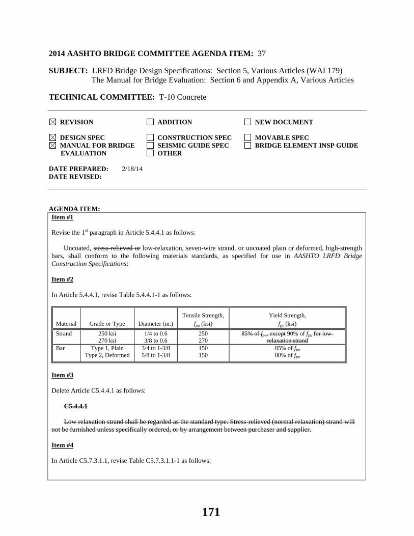
2014 AASHTO BRIDGE COMMITTEE AGENDA ITEM: 37 SUBJECT: LRFD Bridge Design Specifications: Section 5, Various Articles (WAI 179) The Manual for Bridge Evaluation: Section 6 and Appendix A, Various Articles TECHNICAL COMMITTEE: T-10 Concrete
REVISION ADDITION NEW DOCUMENT
DESIGN SPEC CONSTRUCTION SPEC MOVABLE SPEC MANUAL FOR BRIDGE SEISMIC GUIDE SPEC BRIDGE ELEMENT INSP GUIDE
EVALUATION OTHER DATE PREPARED: 2/18/14 DATE REVISED: AGENDA ITEM:Item #1 Revise the 1st paragraph in Article 5.4.4.1 as follows:
Uncoated, stress-relieved or low-relaxation, seven-wire strand, or uncoated plain or deformed, high-strength bars, shall conform to the following materials standards, as specified for use in AASHTO LRFD Bridge Construction Specifications: Item #2 In Article 5.4.4.1, revise Table 5.4.4.1-1 as follows:
Material Grade or Type Diameter (in.) Tensile Strength,
fpu (ksi) Yield Strength,
fpy (ksi) Strand 250 ksi
270 ksi 1/4 to 0.6 3/8 to 0.6
250 270
85% of fpu, except 90% of fpu for low-relaxation strand
Bar Type 1, Plain Type 2, Deformed
3/4 to 1-3/8 5/8 to 1-3/8
150 150
85% of fpu 80% of fpu
Item #3 Delete Article C5.4.4.1 as follows:
C5.4.4.1
Low relaxation strand shall be regarded as the standard type. Stress-relieved (normal relaxation) strand will not be furnished unless specifically ordered, or by arrangement between purchaser and supplier. Item #4 In Article C5.7.3.1.1, revise Table C5.7.3.1.1-1 as follows:
171
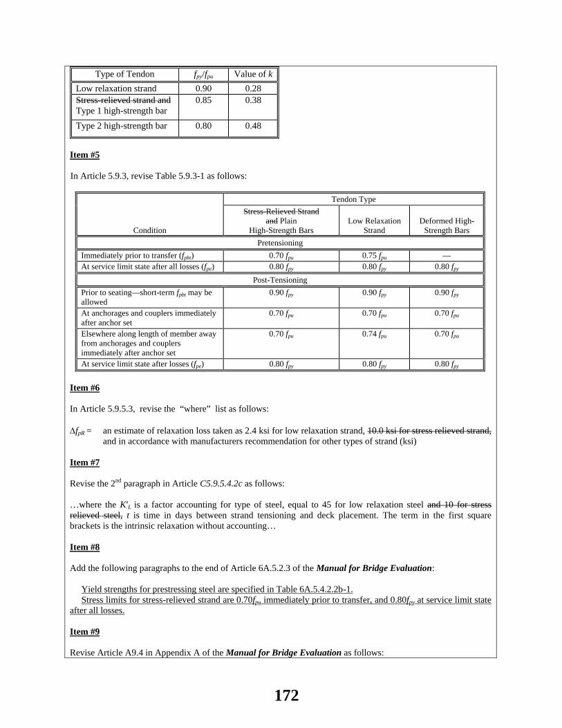
Type of Tendon fpy/fpu Value of k Low relaxation strand 0.90 0.28 Stress-relieved strand and Type 1 high-strength bar
0.85 0.38
Type 2 high-strength bar 0.80 0.48
Item #5 In Article 5.9.3, revise Table 5.9.3-1 as follows:
Condition
Tendon Type Stress-Relieved Strand
and Plain High-Strength Bars
Low Relaxation Strand
Deformed High-Strength Bars
Pretensioning Immediately prior to transfer (fpbt) 0.70 fpu 0.75 fpu — At service limit state after all losses (fpe) 0.80 fpy 0.80 fpy 0.80 fpy
Post-Tensioning Prior to seating—short-term fpbt may be allowed
0.90 fpy 0.90 fpy 0.90 fpy
At anchorages and couplers immediately after anchor set
0.70 fpu 0.70 fpu 0.70 fpu
Elsewhere along length of member away from anchorages and couplers immediately after anchor set
0.70 fpu 0.74 fpu 0.70 fpu
At service limit state after losses (fpe) 0.80 fpy 0.80 fpy 0.80 fpy Item #6 In Article 5.9.5.3, revise the “where” list as follows: ∆fpR = an estimate of relaxation loss taken as 2.4 ksi for low relaxation strand, 10.0 ksi for stress relieved strand,
and in accordance with manufacturers recommendation for other types of strand (ksi) Item #7 Revise the 2nd paragraph in Article C5.9.5.4.2c as follows: …where the K′L is a factor accounting for type of steel, equal to 45 for low relaxation steel and 10 for stress relieved steel, t is time in days between strand tensioning and deck placement. The term in the first square brackets is the intrinsic relaxation without accounting… Item #8 Add the following paragraphs to the end of Article 6A.5.2.3 of the Manual for Bridge Evaluation: Yield strengths for prestressing steel are specified in Table 6A.5.4.2.2b-1. Stress limits for stress-relieved strand are 0.70fpu immediately prior to transfer, and 0.80fpy at service limit state after all losses. Item #9 Revise Article A9.4 in Appendix A of the Manual for Bridge Evaluation as follows:
172
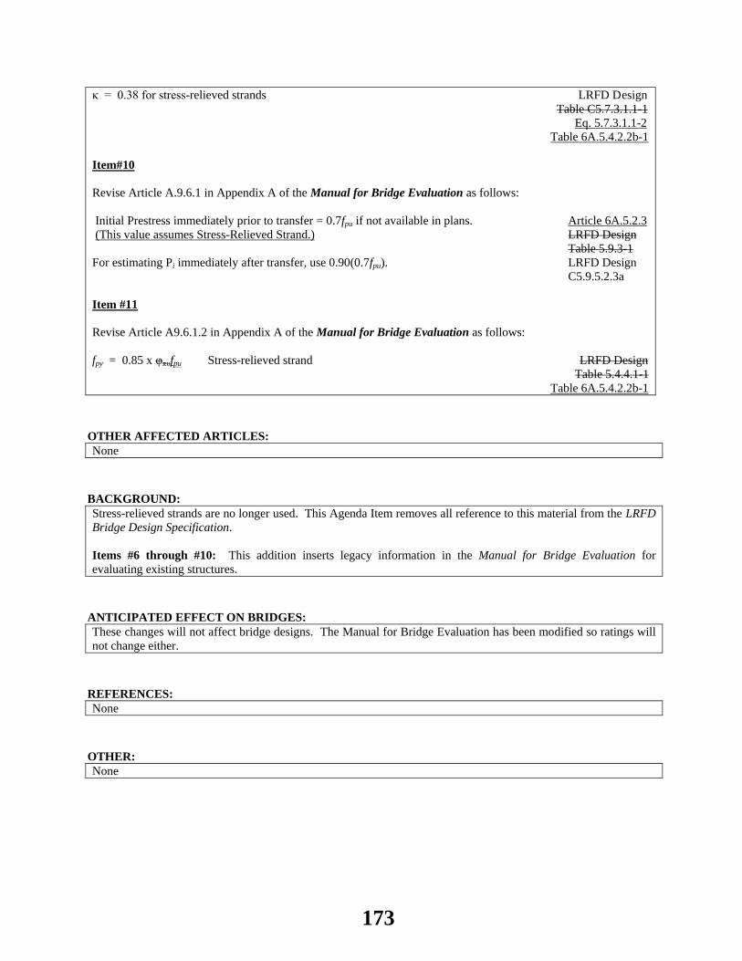
κ = 0.38 for stress-relieved strands LRFD Design Table C5.7.3.1.1-1 Eq. 5.7.3.1.1-2 Table 6A.5.4.2.2b-1 Item#10 Revise Article A.9.6.1 in Appendix A of the Manual for Bridge Evaluation as follows: Initial Prestress immediately prior to transfer = 0.7fpu if not available in plans. Article 6A.5.2.3 (This value assumes Stress-Relieved Strand.) LRFD Design Table 5.9.3-1 For estimating Pi immediately after transfer, use 0.90(0.7fpu). LRFD Design C5.9.5.2.3a Item #11 Revise Article A9.6.1.2 in Appendix A of the Manual for Bridge Evaluation as follows: fpy = 0.85 x φπυfpu Stress-relieved strand LRFD Design Table 5.4.4.1-1 Table 6A.5.4.2.2b-1
OTHER AFFECTED ARTICLES:None
BACKGROUND:Stress-relieved strands are no longer used. This Agenda Item removes all reference to this material from the LRFD Bridge Design Specification. Items #6 through #10: This addition inserts legacy information in the Manual for Bridge Evaluation for evaluating existing structures.
ANTICIPATED EFFECT ON BRIDGES:These changes will not affect bridge designs. The Manual for Bridge Evaluation has been modified so ratings will not change either.
REFERENCES: None
OTHER: None
173

2014 AASHTO BRIDGE COMMITTEE AGENDA ITEM: 38 SUBJECT: LRFD Bridge Design Specifications: Section 13, Articles 13.3, A13.4.3.1 and A13.4.3.2 TECHNICAL COMMITTEE: T-7 Guardrail and Bridge Rail
REVISION ADDITION NEW DOCUMENT
DESIGN SPEC CONSTRUCTION SPEC MOVABLE SPEC MANUAL FOR BRIDGE SEISMIC GUIDE SPEC BRIDGE ELEMENT INSP GUIDE
EVALUATION OTHER DATE PREPARED: 11/12/13 DATE REVISED: 03/28/14 AGENDA ITEM: Item #1 Revise Article 13.3–Notation, as follows: b = length of deck resisting post strength or shear load = h + Wb (A13.4.3.2) (ft) (A13.4.3.1) T = tensile force per unit of deck length (kip/ft) (A13.4.2) (A13.4.3.1) Wb = width of base plate or distribution block (ft); width of base plate (in.) (A13.4.3.1) (A13.4.3.2) Item #2 Revise the 1st paragraph and Eqs. 1, 2 and 5 in Article A13.4.3.1 as follows:
For Design Case I, the moment, per ft in kip-ft/ft, Md, and thrust, per ft in kip/ft of deck, T, may be taken as:
postd
b b
MM
W d=
+
12 post
db b
MM
W d=
+
(A13.4.3.1-1)
p
b b
PT =W + d
12 p
b b
PT =W +d
(A13.4.3.1-2)
174

bb = 2X +W L≤
12bWb = 2X + L≤ (A13.4.3.1-5)
Item #3 Delete the following from the where list in Article A13.4.3.2: b = length of deck resisting post strength or shear load = h + Wb
OTHER AFFECTED ARTICLES:None
BACKGROUND:Correct inconsistent units for moment, Md (kip-ft/ft) and thrust, T (kip/ft) of deck for equations A13.4.3.1-1 and A13.4.3.1-2.
ANTICIPATED EFFECT ON BRIDGES:None
REFERENCES: None
OTHER: Lead State: TX
175

2014 AASHTO BRIDGE COMMITTEE AGENDA ITEM: 39 SUBJECT: LRFD Bridge Design Specifications: Section 13, Article 13.8.2 TECHNICAL COMMITTEE: T-7 Guardrail and Bridge Rail
REVISION ADDITION NEW DOCUMENT
DESIGN SPEC CONSTRUCTION SPEC MOVABLE SPEC MANUAL FOR BRIDGE SEISMIC GUIDE SPEC BRIDGE ELEMENT INSP GUIDE
EVALUATION OTHER DATE PREPARED: 1/29/13 DATE REVISED: 4/15/14 AGENDA ITEM: Add the following sentence at the end of the last paragraph of Article 13.8.2: The wind load need not be applied simultaneously with live load.
OTHER AFFECTED ARTICLES:None
BACKGROUND:Clarifying the effect of chain link or metal fabric fence on the design of rail posts and longitudinal members.
ANTICIPATED EFFECT ON BRIDGES:None
REFERENCES: None
OTHER: None
176

2014 AASHTO BRIDGE COMMITTEE AGENDA ITEM: 40 SUBJECT: LRFD Bridge Design Specifications: Section 3, Article 3.4.1; Section 8, Article C8.4.4.9 (WAI 32) TECHNICAL COMMITTEE: T-5 Loads / T-16 Timber
REVISION ADDITION NEW DOCUMENT
DESIGN SPEC CONSTRUCTION SPEC MOVABLE SPEC MANUAL FOR BRIDGE SEISMIC GUIDE SPEC BRIDGE ELEMENT INSP GUIDE
EVALUATION OTHER DATE PREPARED: 12/09/13 DATE REVISED: 01/17/14 AGENDA ITEM:Item #1 In Article 3.4.1, make the revisions as shown in Attachment A. Item #2 Revise Article C8.4.4.9 as follows:
NDS® and AITC 117-2004 reference design values (based on 10-yr loading) multiplied by the format conversion factors specified in Article 8.4.4.2, transform allowable stress values to strength level stress values based on 10-min. loading. It is assumed that a cumulative duration of bridge live load is two months and the corresponding time effect factor for Strength I is 0.8. A cumulative duration of live load in Strength II is shorter and the corresponding time effect factor for Strength II is 1.0. Resistance of wood subjected to long-duration loads is reduced. Load combination IV consists of emphasizes permanent loads, including dead load and earth pressure.
OTHER AFFECTED ARTICLES:None
BACKGROUND:The current Strength IV load combination was not fully statistically calibrated. It does not include live load and the maximum and minimum dead load factors for DC were 1.5 and 0.9, respectively. That load combination was meant to control for bridges with dead load to live load ratio exceeding 7.0. These are typically long span bridges. The reliability indices determined for this load combination are not uniform and tend to increase with the increase in the dead load to live load ratios, albeit at slow rate for bridges with high ratios. The proposed load combination was developed by Modjeski and Masters, Inc. as part of a special study conducted for AASHTO SCOBS and T-5. While this load combination still emphasizes dead load force effects, it produces a more uniform reliability across the full range of spans and dead load to live load ratios. The level of reliability produced by this load combination is similar to that produced by other Strength limit states. The following graphs show the reliability indices for a database of bridges of different types that was used in the study. The reliability index for Strength I load combination is also shown for reference.
177
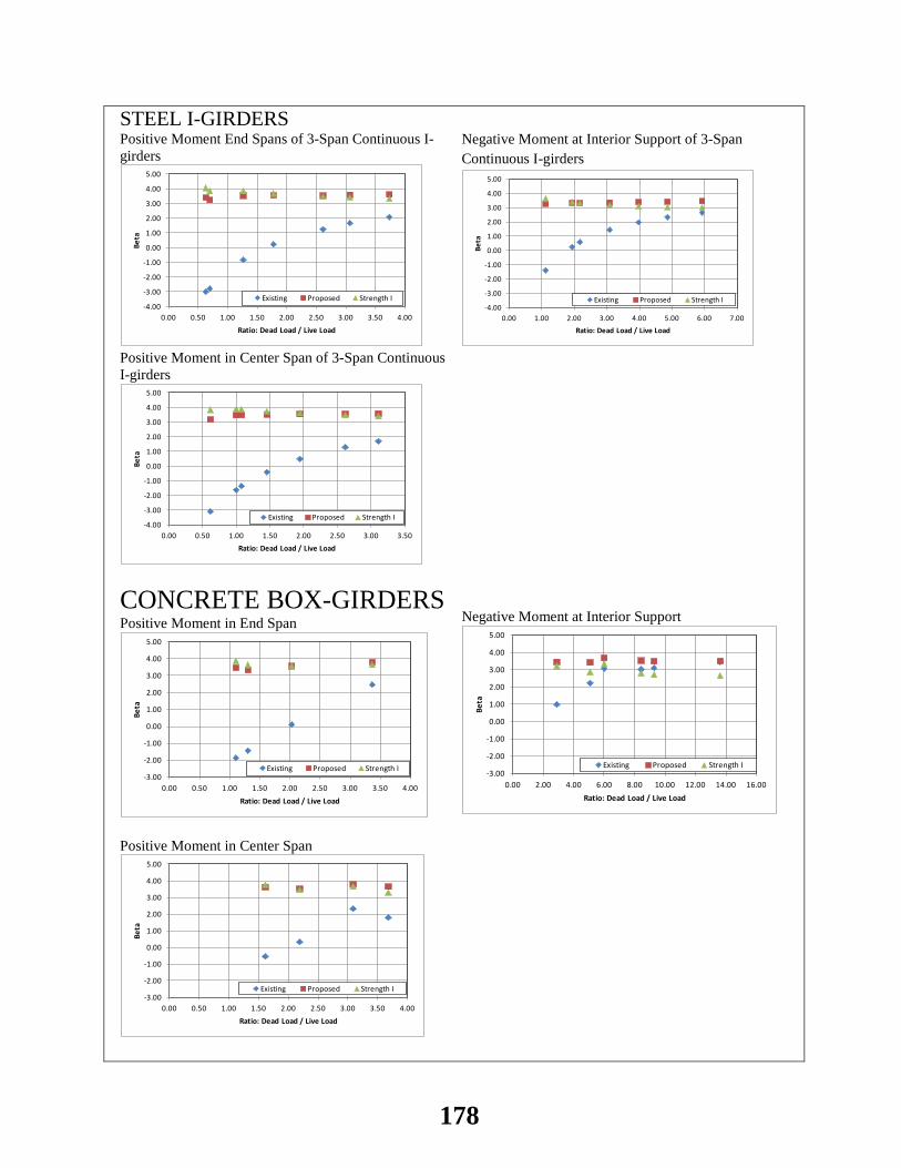
STEEL I-GIRDERS Positive Moment End Spans of 3-Span Continuous I-girders
-4.00
-3.00
-2.00
-1.00
0.00
1.00
2.00
3.00
4.00
5.00
0.00 0.50 1.00 1.50 2.00 2.50 3.00 3.50 4.00
Beta
Ratio: Dead Load / Live Load
Existing Proposed Strength I
Negative Moment at Interior Support of 3-Span Continuous I-girders
-4.00
-3.00
-2.00
-1.00
0.00
1.00
2.00
3.00
4.00
5.00
0.00 1.00 2.00 3.00 4.00 5.00 6.00 7.00
Beta
Ratio: Dead Load / Live Load
Existing Proposed Strength I
Positive Moment in Center Span of 3-Span Continuous I-girders
-4.00
-3.00
-2.00
-1.00
0.00
1.00
2.00
3.00
4.00
5.00
0.00 0.50 1.00 1.50 2.00 2.50 3.00 3.50
Beta
Ratio: Dead Load / Live Load
Existing Proposed Strength I
CONCRETE BOX-GIRDERS Positive Moment in End Span
-3.00
-2.00
-1.00
0.00
1.00
2.00
3.00
4.00
5.00
0.00 0.50 1.00 1.50 2.00 2.50 3.00 3.50 4.00
Beta
Ratio: Dead Load / Live Load
Existing Proposed Strength I
Negative Moment at Interior Support
-3.00
-2.00
-1.00
0.00
1.00
2.00
3.00
4.00
5.00
0.00 2.00 4.00 6.00 8.00 10.00 12.00 14.00 16.00
Beta
Ratio: Dead Load / Live Load
Existing Proposed Strength I
Positive Moment in Center Span
-3.00
-2.00
-1.00
0.00
1.00
2.00
3.00
4.00
5.00
0.00 0.50 1.00 1.50 2.00 2.50 3.00 3.50 4.00
Beta
Ratio: Dead Load / Live Load
Existing Proposed Strength I
178

STEEL TRUSSES Chord Force in Simple Span Trusses
0.00
0.50
1.00
1.50
2.00
2.50
3.00
3.50
0.00 1.00 2.00 3.00 4.00 5.00 6.00 7.00
Beta
Ratio: Dead Load / Live Load
Existing Proposed Strength I
End Diagonal Force in Simple Span Trusses
0.00
0.50
1.00
1.50
2.00
2.50
3.00
3.50
0.00 1.00 2.00 3.00 4.00 5.00 6.00 7.00
Beta
Ratio: Dead Load / Live Load
Existing Proposed Strength I
ANTICIPATED EFFECT ON BRIDGES:Bridges to be controlled by the proposed load combination are expected to be the same ones controlled by the current Strength IV load combination.
REFERENCES: Modjeski and Masters, Inc., Evaluation of Strength II And Strength IV Limit States In AASHTO LRFD Bridge Design Specifications, Special Study for AASHTO Subcommittee on Bridges and Structures Technical Committee on Loads (T-5), September 2013.
OTHER: The proposed load combination for Strength IV is: 1.4 DC + 1.5 DW + 1.45 LL. This load combination produces a uniform reliability index for the full range of spans and dead load to live load ratios. The reliability index is around 3.0 for trusses, neglecting the redundancy and importance factors, and around 3.5 for all other bridge types. Following are some of the results excerpted from Modjeski and Masters’ report to T5. Steel I Girders: A group of three-span continuous steel I girders were investigated with span lengths ranging from 100 ft to 600 ft. This load combination did not control steel I-girders with spans less than 300 ft. For longer spans, it started to control some of the load effects. For 600 ft. long spans, this load combination controlled the negative moment in continuous spans 6 percent over Strength I and for other load effects it controlled by no more 4%. Current strength IV load combination did not control for any load effects.
Force Effect
M+end 0.36-0.86 0.91-1.03
M-Pier 0.53-0.96 0.95-1.06
M+center 0.36-0.82 0.91-1.02
Vend 0.34-0.78 0.91-1.01 VPier,Left 0.47-0.87 0.94-1.04 VPier,Right 0.47-0.86 0.94-1.03
Concrete Girders: Five concrete box girders with spans reaching 508 ft. were investigate. The range of ratios of the load effects for this load combination and for the current Strength IV, both normalized by Strength I load effects, are shown in the following table. The higher ratios were typically associated with the longer spans. It should be noted that when the proposed load combination significantly controls over Strength I, the current Strength IV also controls over Strength I. For example, for negative moment at interior piers the largest ratio for the proposed
179
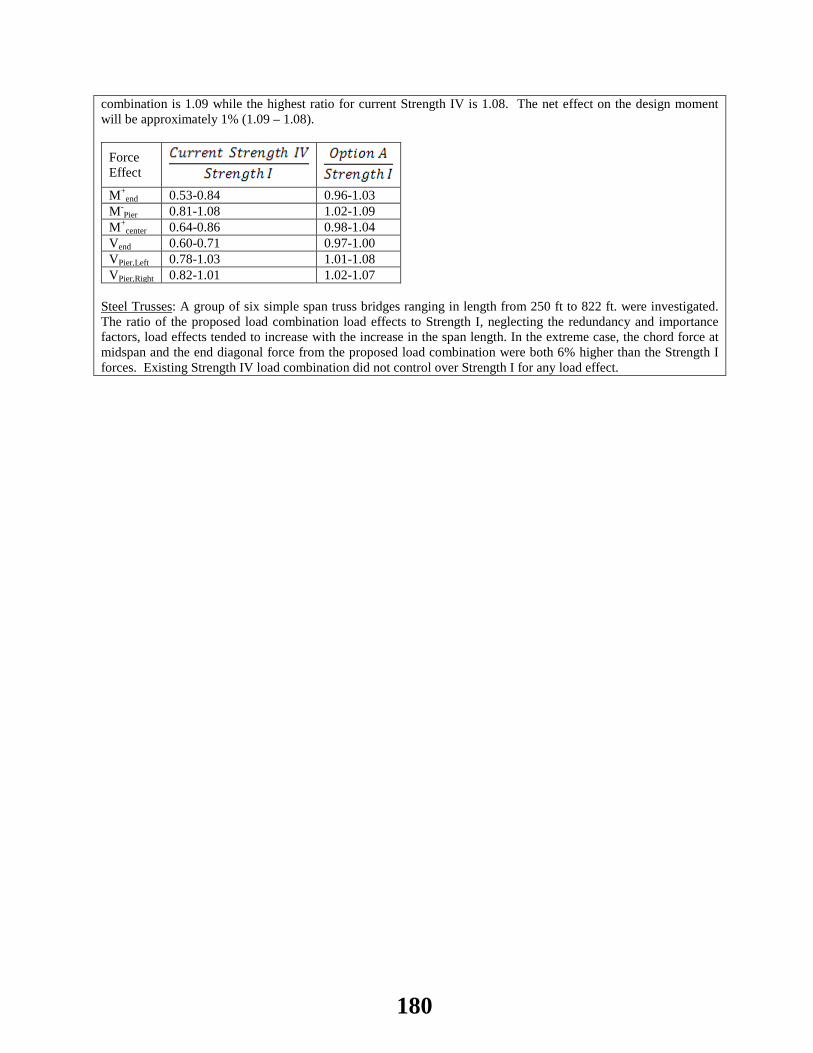
combination is 1.09 while the highest ratio for current Strength IV is 1.08. The net effect on the design moment will be approximately 1% (1.09 – 1.08).
Force Effect M+
end 0.53-0.84 0.96-1.03 M-
Pier 0.81-1.08 1.02-1.09 M+
center 0.64-0.86 0.98-1.04 Vend 0.60-0.71 0.97-1.00 VPier,Left 0.78-1.03 1.01-1.08 VPier,Right 0.82-1.01 1.02-1.07
Steel Trusses: A group of six simple span truss bridges ranging in length from 250 ft to 822 ft. were investigated. The ratio of the proposed load combination load effects to Strength I, neglecting the redundancy and importance factors, load effects tended to increase with the increase in the span length. In the extreme case, the chord force at midspan and the end diagonal force from the proposed load combination were both 6% higher than the Strength I forces. Existing Strength IV load combination did not control over Strength I for any load effect.
180
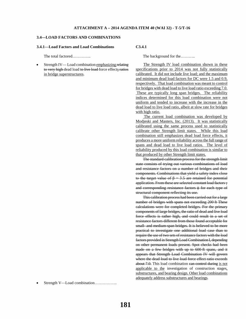
ATTACHMENT A – 2014 AGENDA ITEM 40 (WAI 32) - T-5/T-16
3.4—LOAD FACTORS AND COMBINATIONS 3.4.1—Load Factors and Load Combinations
The total factored…………..
C3.4.1
The background for the………..
• Strength IV— Load combination emphasizing relating to very high dead load to live load force effects ratios in bridge superstructures.
The Strength IV load combination shown in these specifications prior to 2014 was not fully statistically calibrated. It did not include live load; and the maximum and minimum dead load factors for DC were 1.5 and 0.9, respectively. That load combination was meant to control for bridges with dead load to live load ratio exceeding 7.0. These are typically long span bridges. The reliability indices determined for this load combination were not uniform and tended to increase with the increase in the dead load to live load ratio, albeit at slow rate for bridges with high ratio.
The current load combination was developed by Modjeski and Masters, Inc. (2013). It was statistically calibrated using the same process used to statistically calibrate other Strength limit states. While this load combination still emphasizes dead load force effects, it produces a more uniform reliability across the full range of spans and dead load to live load ratios. The level of reliability produced by this load combination is similar to that produced by other Strength limit states.
The standard calibration process for the strength limit state consists of trying out various combinations of load and resistance factors on a number of bridges and their components. Combinations that yield a safety index close to the target value of β = 3.5 are retained for potential application. From these are selected constant load factors γ and corresponding resistance factors φ for each type of structural component reflecting its use.
This calibration process had been carried out for a large number of bridges with spans not exceeding 200 ft These calculations were for completed bridges. For the primary components of large bridges, the ratio of dead and live load force effects is rather high, and could result in a set of resistance factors different from those found acceptable for small- and medium-span bridges. It is believed to be more practical to investigate one additional load case than to require the use of two sets of resistance factors with the load factors provided in Strength Load Combination I, depending on other permanent loads present. Spot checks had been made on a few bridges with up to 600-ft spans, and it appears that Strength Load Combination IV will govern where the dead load to live load force effect ratio exceeds about 7.0. This load combination can control during is not applicable to the investigation of construction stages, substructures, and bearing design. Other load combinations adequately address substructures and bearings.
• Strength V—Load combination……………..
181
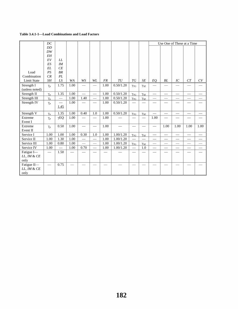
Table 3.4.1-1—Load Combinations and Load Factors
Load Combination Limit State
DC DD DW EH EV ES EL PS CR SH
LL IM CE BR PL LS WA WS WL FR TU TG SE
Use One of These at a Time
EQ BL IC CT CV Strength I (unless noted)
γp 1.75 1.00 — — 1.00 0.50/1.20 γTG γSE — — — — —
Strength II γp 1.35 1.00 — — 1.00 0.50/1.20 γTG γSE — — — — — Strength III γp — 1.00 1.40 — 1.00 0.50/1.20 γTG γSE — — — — — Strength IV γp —
1.45 1.00 — — 1.00 0.50/1.20 — — — — — — —
Strength V γp 1.35 1.00 0.40 1.0 1.00 0.50/1.20 γTG γSE — — — — — Extreme Event I
γp γEQ 1.00 — — 1.00 — — — 1.00 — — — —
Extreme Event II
γp 0.50 1.00 — — 1.00 — — — — 1.00 1.00 1.00 1.00
Service I 1.00 1.00 1.00 0.30 1.0 1.00 1.00/1.20 γTG γSE — — — — — Service II 1.00 1.30 1.00 — — 1.00 1.00/1.20 — — — — — — — Service III 1.00 0.80 1.00 — — 1.00 1.00/1.20 γTG γSE — — — — — Service IV 1.00 — 1.00 0.70 — 1.00 1.00/1.20 — 1.0 — — — — — Fatigue I—LL, IM & CE only
— 1.50 — — — — — — — — — — — —
Fatigue II—LL, IM & CE only
— 0.75 — — — — — — — — — — — —
182
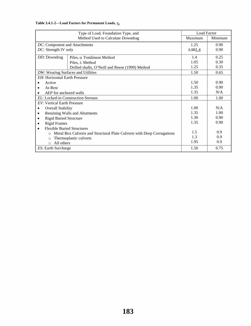
Table 3.4.1-2—Load Factors for Permanent Loads, γp
Type of Load, Foundation Type, and Method Used to Calculate Downdrag
Load Factor Maximum Minimum
DC: Component and Attachments DC: Strength IV only
1.25 1.501.4
0.90 0.90
DD: Downdrag Piles, α Tomlinson Method Piles, λ Method Drilled shafts, O’Neill and Reese (1999) Method
1.4 1.05 1.25
0.25 0.30 0.35
DW: Wearing Surfaces and Utilities 1.50 0.65 EH: Horizontal Earth Pressure • Active • At-Rest • AEP for anchored walls
1.50 1.35 1.35
0.90 0.90 N/A
EL: Locked-in Construction Stresses 1.00 1.00 EV: Vertical Earth Pressure • Overall Stability • Retaining Walls and Abutments • Rigid Buried Structure • Rigid Frames • Flexible Buried Structures
o Metal Box Culverts and Structural Plate Culverts with Deep Corrugations o Thermoplastic culverts o All others
1.00 1.35 1.30 1.35
1.5 1.3
1.95
N/A 1.00 0.90 0.90
0.9 0.9 0.9
ES: Earth Surcharge 1.50 0.75
183

2014 AASHTO BRIDGE COMMITTEE AGENDA ITEM: 41 SUBJECT: LRFD Bridge Design Specifications: Section 3, Article C3.6.1.2.1 (WAI 51) TECHNICAL COMMITTEE: T-5 Loads
REVISION ADDITION NEW DOCUMENT
DESIGN SPEC CONSTRUCTION SPEC MOVABLE SPEC MANUAL FOR BRIDGE SEISMIC GUIDE SPEC BRIDGE ELEMENT INSP GUIDE
EVALUATION OTHER DATE PREPARED: 11/21/13 DATE REVISED: 01/06/14 AGENDA ITEM:Revise Articles C3.6.1.2.1 as follows:
C3.6.1.2.1
Consideration should be given to site-specific modifications to the design truck, design tandem, and/or the design lane load under the following conditions:
• The legal load of a given jurisdiction is significantly greater than typical;
• The roadway is expected to carry unusually high percentages of truck traffic;
• Flow control, such as a stop sign, traffic signal, or toll booth, causes trucks to collect on certain areas of a bridge or to not be interrupted by light traffic; or
• Special industrial loads are common due to the location of the bridge. See also discussion in Article C3.6.1.3.1.
The live load model, consisting of either a truck or tandem coincident with a uniformly distributed load, was developed as a notional representation of shear and moment produced by a group of vehicles routinely permitted on highways of various states under “grandfather” exclusions to weight laws. The vehicles considered to be representative of these exclusions were based on a study conducted by the Transportation Research Board (Cohen, 1990). The load model is called “notional” because it is not intended to represent any particular truck.
In the initial development of the notional live load model, no attempt was made to relate to escorted permit loads, illegal overloads, or short duration special permits. The moment and shear effects were subsequently compared to the results of truck weight studies (Csagoly and Knobel, 1981; Nowak, 1992; Kulicki, 2006), selected WIM data, and the 1991 OHBDC live load model. These subsequent comparisons showed that the notional load could be scaled by appropriate load factors to be representative of these other load spectra. Earlier editions of the commentary included information about the background of the HL-93. This information can be found in Kulicki 2006.
The following nomenclature applies to Figures C3.6.1.2.1-1 through C3.6.1.2.1-6, which show results of live load studies involving two equal continuous spans or simple spans:
M POS 0.4L = positive moment at 4/10 point in either span M NEG 0.4L = negative moment at 4/10 point in either span
184

M SUPPORT = moment at interior support Vab = shear adjacent to either exterior support Vba = shear adjacent to interior support Mss = midspan moment in a simply supported span
The “span” is the length of the simple-span or of one of each of the two continuous spans. The comparison is in the form of ratios of the load effects produced in either simple-span or two-span continuous girders. A ratio greater than 1.0 indicates that one or more of the exclusion vehicles produces a larger load effect than the HS20 loading. The figures indicate the degree by which the exclusion loads deviate from the HS loading of designation, e.g., HS25.
Figures C3.6.1.2.1-1 and C3.6.1.2.1-2 show moment and shear comparisons between the envelope of effects caused by 22 truck configurations chosen to be representative of the exclusion vehicles and the HS20 loading, either the HS20 truck or the lane load, or the interstate load consisting of two 24.0-kip axles 4.0 ft apart, as used in previous editions of the AASHTO Standard Specifications. The largest and smallest of the 22 configurations can be found in Kulicki and Mertz (1991). In the case of negative moment at an interior support, the results presented are based on two identical exclusion vehicles in tandem and separated by at least 50.0 ft.
185
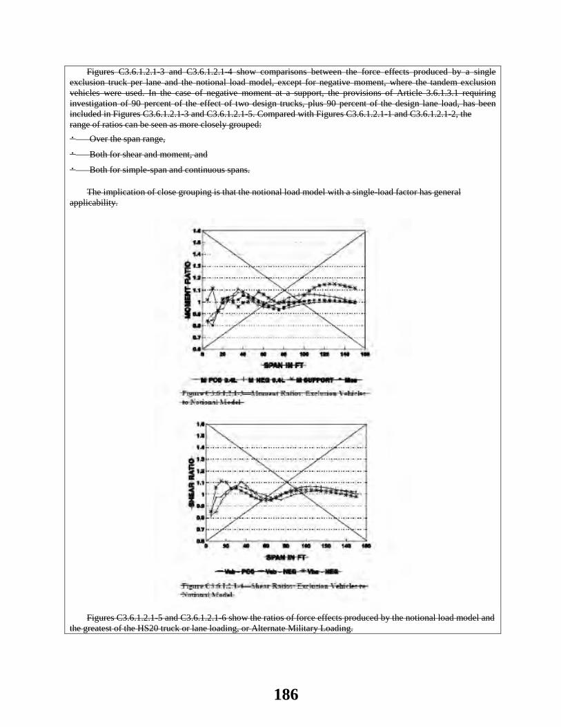
Figures C3.6.1.2.1-3 and C3.6.1.2.1-4 show comparisons between the force effects produced by a single exclusion truck per lane and the notional load model, except for negative moment, where the tandem exclusion vehicles were used. In the case of negative moment at a support, the provisions of Article 3.6.1.3.1 requiring investigation of 90 percent of the effect of two design trucks, plus 90 percent of the design lane load, has been included in Figures C3.6.1.2.1-3 and C3.6.1.2.1-5. Compared with Figures C3.6.1.2.1-1 and C3.6.1.2.1-2, the range of ratios can be seen as more closely grouped: • Over the span range,
• Both for shear and moment, and
• Both for simple-span and continuous spans.
The implication of close grouping is that the notional load model with a single-load factor has general applicability.
Figures C3.6.1.2.1-5 and C3.6.1.2.1-6 show the ratios of force effects produced by the notional load model and
the greatest of the HS20 truck or lane loading, or Alternate Military Loading.
186
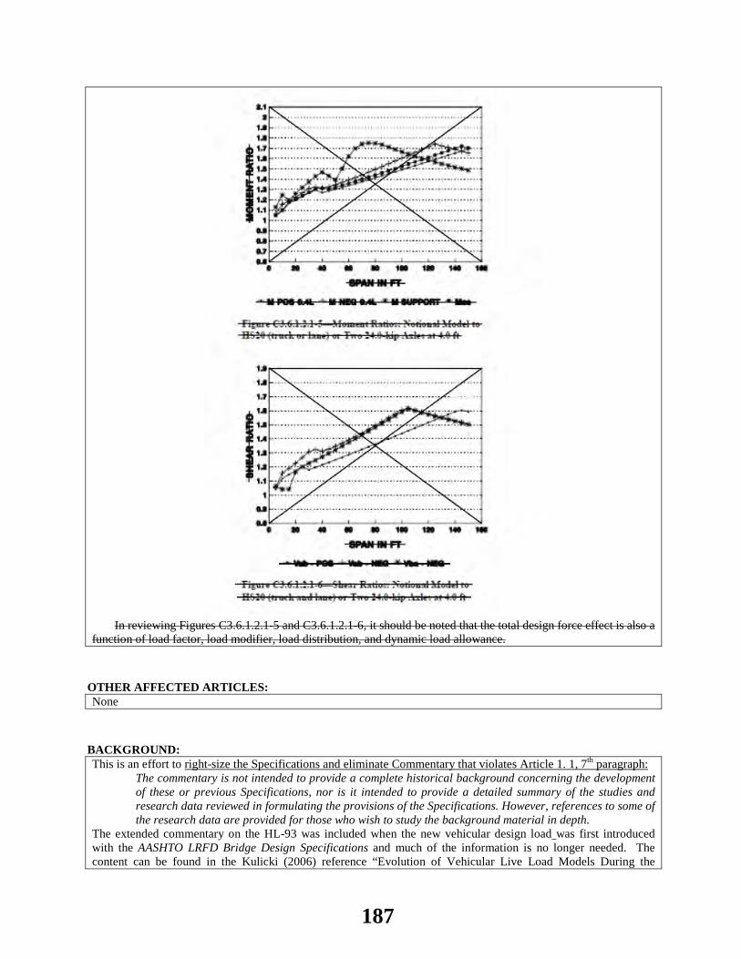
In reviewing Figures C3.6.1.2.1-5 and C3.6.1.2.1-6, it should be noted that the total design force effect is also a
function of load factor, load modifier, load distribution, and dynamic load allowance.
OTHER AFFECTED ARTICLES:None
BACKGROUND:This is an effort to right-size the Specifications and eliminate Commentary that violates Article 1. 1, 7th paragraph:
The commentary is not intended to provide a complete historical background concerning the development of these or previous Specifications, nor is it intended to provide a detailed summary of the studies and research data reviewed in formulating the provisions of the Specifications. However, references to some of the research data are provided for those who wish to study the background material in depth.
The extended commentary on the HL-93 was included when the new vehicular design load was first introduced with the AASHTO LRFD Bridge Design Specifications and much of the information is no longer needed. The content can be found in the Kulicki (2006) reference “Evolution of Vehicular Live Load Models During the
187

Interstate Design Era and Beyond”, in: 50 Years of Interstate Structures: Past, Present and Future”, Transportation Research Circular, E-C104: http://onlinepubs.trb.org/onlinepubs/circulars/ec104.pdf.
ANTICIPATED EFFECT ON BRIDGES:None
REFERENCES: None
OTHER: None
188

2014 AASHTO BRIDGE COMMITTEE AGENDA ITEM: 42 SUBJECT: LRFD Bridge Design Specifications: Section 3, Article 3.10.9.2 TECHNICAL COMMITTEE: T-3 Seismic
REVISION ADDITION NEW DOCUMENT
DESIGN SPEC CONSTRUCTION SPEC MOVABLE SPEC MANUAL FOR BRIDGE SEISMIC GUIDE SPEC COASTAL GUIDE SPEC
EVALUATION OTHER DATE PREPARED: 1/10/14 DATE REVISED: 4/9/14 AGENDA ITEM:Item#1 Delete the third paragraph of Article 3.10.9.2. Item #2 Revise the first paragraph of Article C3.10.9.2 as follows:
These provisions arise because, as specified in Article 4.7.4, seismic analysis for bridges in Zone 1 is not generally required. These default values are used as The minimum connection design forces of this Article are used in lieu of determining such forces through rigorous analysis. The division of Zone 1 at a value for the an acceleration coefficient, As, of 0.05 recognizes that, in parts of the country with very low seismicity, seismic forces on connections are very relatively small. However as outlined below, the intent of this Article is to prevent connections from becoming unintended weak links in the seismic lateral load path. Accordingly, the minimum connection forces specified in this Article are intended to be sufficiently conservative to prevent premature failure and are not intended to precisely reflect the expected dynamic seismic forces. See Article C3.10.7.1 for a description of typical elements considered to be connections, and note that a connection, as considered in this Article, may be an element that simply restrains a member and may not physically connect to that member, such as transverse shear keys. Additionally, anchorage detailing for connections should be extended far enough into the adjacent member to ensure that premature or unintentional local failure is prevented. Similarly, the design of a girder support pedestal should consider the connection forces specified in this Article, since failure of a pedestal located above the main pier cap could potentially lead to loss of span support. Item #3 Replace the second paragraph of Article C3.10.9.2 with the following:
In Zone 1, the prevention of superstructure collapse due to unseating of spans is the primary objective behind the provisions for minimum connection forces in restrained directions, as covered by this Article, and for minimum support lengths for unrestrained directions (e.g. expansion bearings), as covered by Article 4.7.4.4. The minimum connection forces specified in this Article are not intended to be minimum design forces for the bridge, because the main elements of the bridge in Zone 1 should generally be capable of resisting the expected lateral seismic forces, by virtue of satisfying the nonseismic design requirements. However, this presumed structural resistance is predicated on providing sufficient integrity and connectivity within the structure to mobilize the lateral resistance of the main structural elements (e.g. columns, pier caps, superstructure, abutments and foundations).
Accordingly, the design forces for connections need only be considered for those elements that directly prevent
189
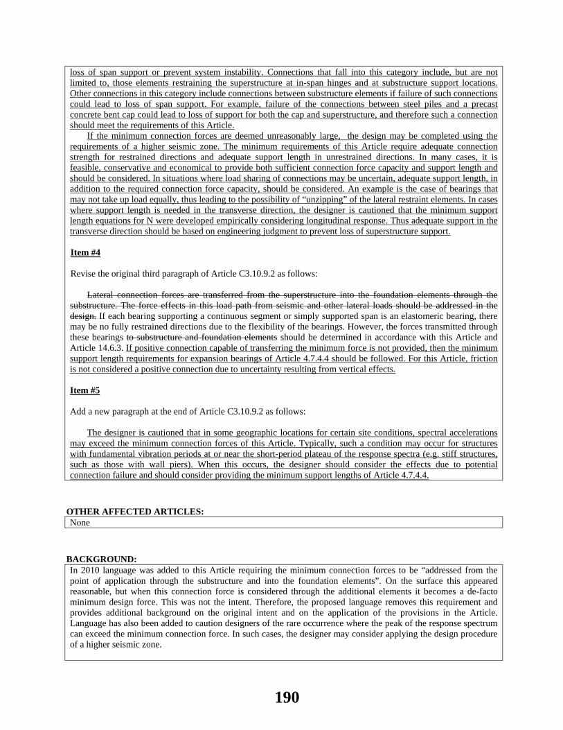
loss of span support or prevent system instability. Connections that fall into this category include, but are not limited to, those elements restraining the superstructure at in-span hinges and at substructure support locations. Other connections in this category include connections between substructure elements if failure of such connections could lead to loss of span support. For example, failure of the connections between steel piles and a precast concrete bent cap could lead to loss of support for both the cap and superstructure, and therefore such a connection should meet the requirements of this Article.
If the minimum connection forces are deemed unreasonably large, the design may be completed using the requirements of a higher seismic zone. The minimum requirements of this Article require adequate connection strength for restrained directions and adequate support length in unrestrained directions. In many cases, it is feasible, conservative and economical to provide both sufficient connection force capacity and support length and should be considered. In situations where load sharing of connections may be uncertain, adequate support length, in addition to the required connection force capacity, should be considered. An example is the case of bearings that may not take up load equally, thus leading to the possibility of “unzipping” of the lateral restraint elements. In cases where support length is needed in the transverse direction, the designer is cautioned that the minimum support length equations for N were developed empirically considering longitudinal response. Thus adequate support in the transverse direction should be based on engineering judgment to prevent loss of superstructure support. Item #4 Revise the original third paragraph of Article C3.10.9.2 as follows:
Lateral connection forces are transferred from the superstructure into the foundation elements through the substructure. The force effects in this load path from seismic and other lateral loads should be addressed in the design. If each bearing supporting a continuous segment or simply supported span is an elastomeric bearing, there may be no fully restrained directions due to the flexibility of the bearings. However, the forces transmitted through these bearings to substructure and foundation elements should be determined in accordance with this Article and Article 14.6.3. If positive connection capable of transferring the minimum force is not provided, then the minimum support length requirements for expansion bearings of Article 4.7.4.4 should be followed. For this Article, friction is not considered a positive connection due to uncertainty resulting from vertical effects. Item #5 Add a new paragraph at the end of Article C3.10.9.2 as follows:
The designer is cautioned that in some geographic locations for certain site conditions, spectral accelerations may exceed the minimum connection forces of this Article. Typically, such a condition may occur for structures with fundamental vibration periods at or near the short-period plateau of the response spectra (e.g. stiff structures, such as those with wall piers). When this occurs, the designer should consider the effects due to potential connection failure and should consider providing the minimum support lengths of Article 4.7.4.4.
OTHER AFFECTED ARTICLES:None
BACKGROUND:In 2010 language was added to this Article requiring the minimum connection forces to be “addressed from the point of application through the substructure and into the foundation elements”. On the surface this appeared reasonable, but when this connection force is considered through the additional elements it becomes a de-facto minimum design force. This was not the intent. Therefore, the proposed language removes this requirement and provides additional background on the original intent and on the application of the provisions in the Article. Language has also been added to caution designers of the rare occurrence where the peak of the response spectrum can exceed the minimum connection force. In such cases, the designer may consider applying the design procedure of a higher seismic zone.
190

Unfortunately, when the Standard Specifications Division I-A seismic provisions were brought into the LRFD specification the introductory commentary was substantially condensed to fit into the LRFD specifications. One of the omitted paragraphs provided clarification to the Seismic Zone 1 (previously SPC A) requirements. The description of the intent of the Zone 1 requirements has been restored with the proposed revisions. For reference the omitted paragraph from Division I-A is included below:
“For bridges classified as SPC A, prevention of superstructure collapse is all that was deemed necessary for their level of seismic exposure. The requirements for these bridges is minimal and specify the support lengths for girders at abutments, columns and expansion joints, and that the design of connections of the superstructure to the substructure be for 0.20 times the dead load reaction forces.” From: Division I-A Commentary, Section 1, Eighth Paragraph, page C-38. Note this is also verbatim from ATC-6, which was the source document for Division I-A.
As the seismic design provisions have evolved, several other enhancements to Zone 1 have been added, such as minimum detailing and two levels of requirements within Zone 1. For the most part these have been included to address the slight shift in seismic zone boundaries when the seismic hazard was changed to 7 percent probability of exceedence in 75 years. Those provisions are not affected by this ballot item.
ANTICIPATED EFFECT ON BRIDGES:Improved seismic design guidelines and more economical bridge designs.
REFERENCES: Standard Specifications for Highway Bridges (2002) 17th Edition, 1998 Commentary, Division I-A ATC-6 Seismic Design Guidelines for Highway Bridges (1981) Applied Technology Council.
OTHER: None
191
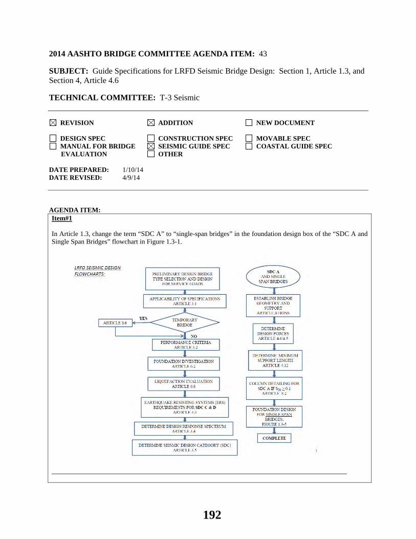
2014 AASHTO BRIDGE COMMITTEE AGENDA ITEM: 43 SUBJECT: Guide Specifications for LRFD Seismic Bridge Design: Section 1, Article 1.3, and Section 4, Article 4.6 TECHNICAL COMMITTEE: T-3 Seismic
REVISION ADDITION NEW DOCUMENT
DESIGN SPEC CONSTRUCTION SPEC MOVABLE SPEC MANUAL FOR BRIDGE SEISMIC GUIDE SPEC COASTAL GUIDE SPEC
EVALUATION OTHER DATE PREPARED: 1/10/14 DATE REVISED: 4/9/14 AGENDA ITEM:Item#1 In Article 1.3, change the term “SDC A” to “single-span bridges” in the foundation design box of the “SDC A and Single Span Bridges” flowchart in Figure 1.3-1.
192
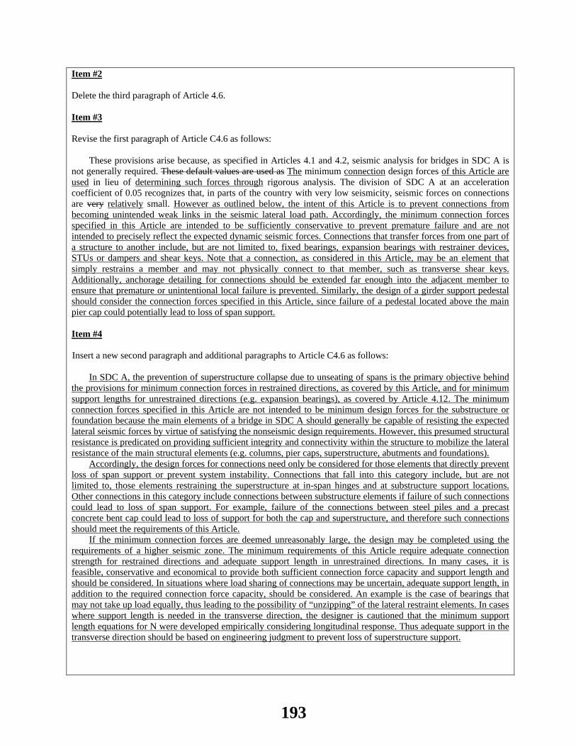
Item #2
Delete the third paragraph of Article 4.6.
Item #3
Revise the first paragraph of Article C4.6 as follows:
These provisions arise because, as specified in Articles 4.1 and 4.2, seismic analysis for bridges in SDC A is not generally required. These default values are used as The minimum connection design forces of this Article are used in lieu of determining such forces through rigorous analysis. The division of SDC A at an acceleration coefficient of 0.05 recognizes that, in parts of the country with very low seismicity, seismic forces on connections are very relatively small. However as outlined below, the intent of this Article is to prevent connections from becoming unintended weak links in the seismic lateral load path. Accordingly, the minimum connection forces specified in this Article are intended to be sufficiently conservative to prevent premature failure and are not intended to precisely reflect the expected dynamic seismic forces. Connections that transfer forces from one part of a structure to another include, but are not limited to, fixed bearings, expansion bearings with restrainer devices, STUs or dampers and shear keys. Note that a connection, as considered in this Article, may be an element that simply restrains a member and may not physically connect to that member, such as transverse shear keys. Additionally, anchorage detailing for connections should be extended far enough into the adjacent member to ensure that premature or unintentional local failure is prevented. Similarly, the design of a girder support pedestal should consider the connection forces specified in this Article, since failure of a pedestal located above the main pier cap could potentially lead to loss of span support.
Item #4
Insert a new second paragraph and additional paragraphs to Article C4.6 as follows:
In SDC A, the prevention of superstructure collapse due to unseating of spans is the primary objective behind the provisions for minimum connection forces in restrained directions, as covered by this Article, and for minimum support lengths for unrestrained directions (e.g. expansion bearings), as covered by Article 4.12. The minimum connection forces specified in this Article are not intended to be minimum design forces for the substructure or foundation because the main elements of a bridge in SDC A should generally be capable of resisting the expected lateral seismic forces by virtue of satisfying the nonseismic design requirements. However, this presumed structural resistance is predicated on providing sufficient integrity and connectivity within the structure to mobilize the lateral resistance of the main structural elements (e.g. columns, pier caps, superstructure, abutments and foundations).
Accordingly, the design forces for connections need only be considered for those elements that directly prevent loss of span support or prevent system instability. Connections that fall into this category include, but are not limited to, those elements restraining the superstructure at in-span hinges and at substructure support locations. Other connections in this category include connections between substructure elements if failure of such connections could lead to loss of span support. For example, failure of the connections between steel piles and a precast concrete bent cap could lead to loss of support for both the cap and superstructure, and therefore such connections should meet the requirements of this Article.
If the minimum connection forces are deemed unreasonably large, the design may be completed using the requirements of a higher seismic zone. The minimum requirements of this Article require adequate connection strength for restrained directions and adequate support length in unrestrained directions. In many cases, it is feasible, conservative and economical to provide both sufficient connection force capacity and support length and should be considered. In situations where load sharing of connections may be uncertain, adequate support length, in addition to the required connection force capacity, should be considered. An example is the case of bearings that may not take up load equally, thus leading to the possibility of “unzipping” of the lateral restraint elements. In cases where support length is needed in the transverse direction, the designer is cautioned that the minimum support length equations for N were developed empirically considering longitudinal response. Thus adequate support in the transverse direction should be based on engineering judgment to prevent loss of superstructure support.
193

Item #5
Revise the original second paragraph of Article C4.6 as follows:
Lateral connection forces are transferred from the superstructure into the foundation elements through the substructure. The force effects in this load path from seismic and other lateral loads should be addressed in the design. If each bearing supporting a continuous segment or simply supported span is an elastomeric bearing, there may be no fully restrained directions due to flexibility of the bearings. However, the forces transmitted through these bearings to substructure and foundation elements should be determined in accordance with this Article and Article 14.6.3 of AASHTO LRFD Bridge Design Specifications. If positive connection capable of transferring the minimum force is not provided, then the minimum support length requirements for expansion bearings of Article 4.12 should be followed. For this Article, friction is not considered a positive connection due to uncertainty resulting from vertical effects.
Item #6
Add a new paragraph at the end of Article C4.6 as follows:
The designer is cautioned that in some geographic locations for certain site conditions, spectral accelerations may exceed the minimum connection forces of this Article. Typically, such a condition may occur for structures with fundamental vibration periods at or near the short-period plateau of the response spectra (e.g. stiff structures, such as those with wall piers). When this occurs, the designer should consider the effects due to potential connection failure and should consider providing the minimum support lengths of Article 4.12.
OTHER AFFECTED ARTICLES:None
BACKGROUND:In 2010 language was added to this Article requiring the minimum connection forces to be “addressed from the point of application through the substructure and into the foundation elements”. On the surface this appeared reasonable, but when this connection force is considered through the additional elements it becomes a de-facto minimum design force. This was not the intent. Therefore, the proposed language removes this requirement and provides additional background on the original intent and on the application of the provisions in the Article. Language has also been added to caution designers of the rare occurrence where the peak of the response spectrum can exceed the minimum connection force. In such cases, the designer may consider applying the design procedure of a higher seismic zone.
Unfortunately, when the Standard Specifications Division I-A seismic provisions were brought into the LRFD specification the introductory commentary was substantially condensed to fit into the LRFD specifications. The LRFD Seismic Zone 1 requirements were subsequently taken, essentially verbatim, into the Seismic Guide Specifications. One of the omitted paragraphs provided clarification to the Seismic Zone 1 (previously SPC A, and SDC A in the SGS) requirements. The description of the intent of the SDC A requirements has been restored with the proposed revisions. For reference the omitted paragraph from Division I-A is included below:
“For bridges classified as SPC A, prevention of superstructure collapse is all that was deemed necessary for their level of seismic exposure. The requirements for these bridges is minimal and specify the support lengths for girders at abutments, columns and expansion joints, and that the design of connections of the superstructure to the substructure be for 0.20 times the dead load reaction forces.”
From: Division I-A Commentary, Section 1, Eighth Paragraph, page C-38. Note this is also verbatim from ATC-6, which was the source document for Division I-A.
As the seismic design provisions have evolved, several other enhancements to SDC A have been added, such as
194

minimum detailing and two levels of requirements within SDC A. For the most part these have been included to address the slight shift in seismic zone boundaries when the seismic hazard was changed to 7 percent probability of exceedence in 75 years. Those provisions are not affected by this ballot item.
ANTICIPATED EFFECT ON BRIDGES:Improved seismic design guidelines and more economical bridge designs.
REFERENCES: Standard Specifications for Highway Bridges (2002) 17th Edition, 1998 Commentary, Division I-A
AASHTO LRFD Bridge Design Specifications (2013).
ATC-6 Seismic Design Guidelines for Highway Bridges (1981) Applied Technology Council.
OTHER: None
195
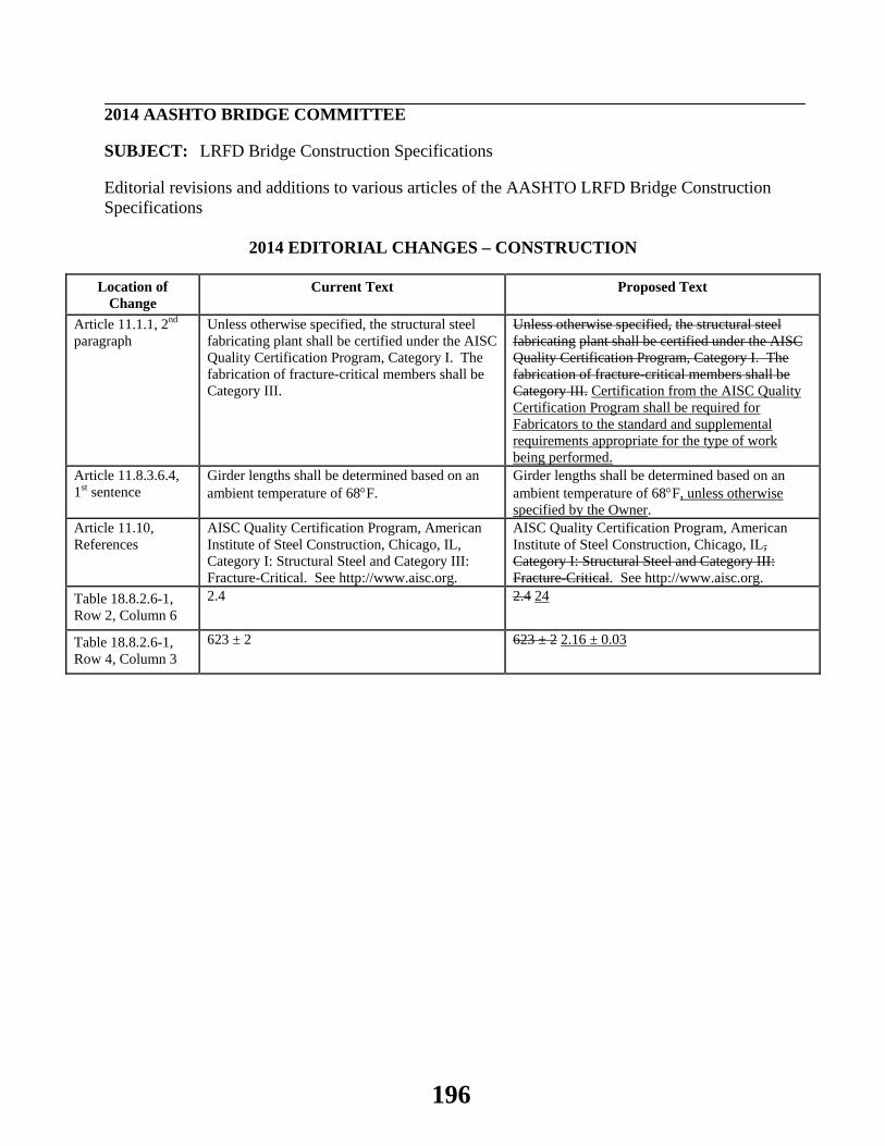
2014 AASHTO BRIDGE COMMITTEE
SUBJECT: LRFD Bridge Construction Specifications
Editorial revisions and additions to various articles of the AASHTO LRFD Bridge Construction Specifications
2014 EDITORIAL CHANGES – CONSTRUCTION
Location of Change
Current Text Proposed Text
Article 11.1.1, 2nd paragraph
Unless otherwise specified, the structural steel fabricating plant shall be certified under the AISC Quality Certification Program, Category I. The fabrication of fracture-critical members shall be Category III.
Unless otherwise specified, the structural steel fabricating plant shall be certified under the AISC Quality Certification Program, Category I. The fabrication of fracture-critical members shall be Category III. Certification from the AISC Quality Certification Program shall be required for Fabricators to the standard and supplemental requirements appropriate for the type of work being performed.
Article 11.8.3.6.4, 1st sentence
Girder lengths shall be determined based on an ambient temperature of 68°F.
Girder lengths shall be determined based on an ambient temperature of 68°F, unless otherwise specified by the Owner.
Article 11.10, References
AISC Quality Certification Program, American Institute of Steel Construction, Chicago, IL, Category I: Structural Steel and Category III: Fracture-Critical. See http://www.aisc.org.
AISC Quality Certification Program, American Institute of Steel Construction, Chicago, IL, Category I: Structural Steel and Category III: Fracture-Critical. See http://www.aisc.org.
Table 18.8.2.6-1, Row 2, Column 6
2.4 2.4 24
Table 18.8.2.6-1, Row 4, Column 3
623 ± 2 623 ± 2 2.16 ± 0.03
196

2014 AASHTO BRIDGE COMMITTEE
SUBJECT: LRFD Bridge Design Specifications
Editorial revisions and additions to various articles of the AASHTO LRFD Bridge Design Specifications
2014 EDITORIAL CHANGES – DESIGN
Location of Change Current Text Proposed Text Article 3.4.1, 2nd paragraph Components and connections of a
bridge shall satisfy Eq. 1.3.2.1-1 for the applicable combinations of factored extreme force effects as specified at each of the following limit states:
Components and connections of a bridge shall satisfy Eq. 1.3.2.1-1 for the applicable combinations of factored extreme force effects as specified at each of the load combinations specified in Table 3.4.1-1 at the following limit states:
Article C4.6.3.3.2, 4th paragraph, last sentence
Additional information on the modeling of torsion in I-girder bridges may be found in AASHTO/NSBA (2011).
Additional information on the modeling of torsion in I-girder bridges may be found in AASHTO/NSBA (20112014).
Article 4.9, References AASHTO/NSBA Steel Bridge Collaboration. 2011. Guidelines for Steel Girder Bridge Analysis, G13.1, 1st edition, NSBASGBA-1, American Association of State Highway and Transportation Officials, Washington, DC.
AASHTO/NSBA Steel Bridge Collaboration. 20112014. Guidelines for Steel Girder Bridge Analysis, G13.1, 1st 2nd edition, NSBASGBA-12, American Association of State Highway and Transportation Officials, Washington, DC.
Article 5.10.5, add to the end of this article
--- External tendon supports in curved concrete box girders shall be located far enough away from the web to prevent the free length of tendon from bearing on the web at locations away from the supports. When deviation saddles are required for this purpose, they shall be designed in accordance with Article 5.10.9.3.7.
Article 5.13.2.2, add as the 2nd paragraph
--- Intermediate diaphragms may be used between beams in curved systems or where necessary to provide torsional resistance and to support the deck at points of discontinuity or at right angle points of discontinuity or at angle points in girders.
Table 6.6.1.2.3-1, Condition 4.3, Description
--- In the second paragraph of the Description, move the E and E′ lines up to line up with ′Stiffener thickness < 1.0 in.′ and ′Stiffener thickness ≥ 1.0 in.′, respectively.
Table 6.6.1.2.3-1, Conditions 5.1, 5.2 and 6.1, ′Constant A′ column
--- Remove the wrap on the value ′120 x 108′.
197
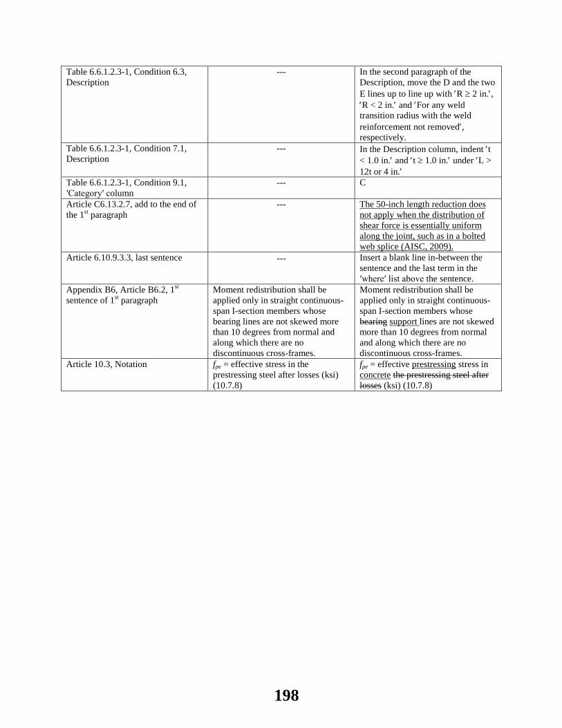
Table 6.6.1.2.3-1, Condition 6.3, Description
--- In the second paragraph of the Description, move the D and the two E lines up to line up with ′R ≥ 2 in.′, ′R < 2 in.′ and ′For any weld transition radius with the weld reinforcement not removed′, respectively.
Table 6.6.1.2.3-1, Condition 7.1, Description
--- In the Description column, indent ′t < 1.0 in.′ and ′t ≥ 1.0 in.′ under ′L > 12t or 4 in.′
Table 6.6.1.2.3-1, Condition 9.1, ′Category′ column
--- C
Article C6.13.2.7, add to the end of the 1st paragraph
--- The 50-inch length reduction does not apply when the distribution of shear force is essentially uniform along the joint, such as in a bolted web splice (AISC, 2009).
Article 6.10.9.3.3, last sentence --- Insert a blank line in-between the sentence and the last term in the ′where′ list above the sentence.
Appendix B6, Article B6.2, 1st sentence of 1st paragraph
Moment redistribution shall be applied only in straight continuous-span I-section members whose bearing lines are not skewed more than 10 degrees from normal and along which there are no discontinuous cross-frames.
Moment redistribution shall be applied only in straight continuous-span I-section members whose bearing support lines are not skewed more than 10 degrees from normal and along which there are no discontinuous cross-frames.
Article 10.3, Notation fpe = effective stress in the prestressing steel after losses (ksi) (10.7.8)
fpe = effective prestressing stress in concrete the prestressing steel after losses (ksi) (10.7.8)
198

2014 AASHTO BRIDGE COMMITTEE
SUBJECT: LRFD Guide Specifications for the Design of Pedestrian Bridges
Editorial revisions and additions to various articles of the AASHTO LRFD Guide Specifications for the Design of Pedestrian Bridges
2014 EDITORIAL CHANGES – PEDESTRIAN
Location of Change
Current Text Proposed Text
Article 7.2.2, where list
L = effective buckling length for lateral-torsional buckling (ft)
L = effective buckling length for lateral-torsional buckling (ft) (in.)
199

Chair Gregg Fredrick, P.E.
Assistant Chief Engineer, Engineering and Planning Wyoming Department of Transportation
Phone: 307-777-4484 Email: [email protected]
Vice Chair Bruce V. Johnson, P.E. State Bridge Engineer
Oregon Department of Transportation Phone: 503-986-3344
Email: [email protected]
Secretary Joseph L. Hartmann, PhD, P.E.
Director, Office of Bridges and Structures Federal Highway Administration
Phone: 202-366-4599 Email: [email protected]
Liaison Patricia J. Bush, P.E.
Program Manager for Bridges and Structures American Association of State Highway and
Transportation Officials Phone: 202-624-8181
Email: [email protected]
200
American Association of State Highway and Transportation OfficialsStanding Committee on Highways
Subcommittee on Bridges and Structures
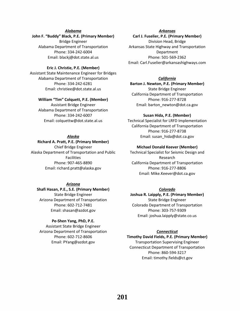
Alabama Arkansas John F. “Buddy” Black, P.E. (Primary Member) Carl J. Fuselier, P.E. (Primary Member)
Bridge Engineer Division Head, Bridge Alabama Department of Transportation Arkansas State Highway and Transportation
Department Phone: 334-242-6004 Email: [email protected] Phone: 501-569-2362
Email: [email protected] Eric J. Christie, P.E. (Member)
Assistant State Maintenance Engineer for Bridges Alabama Department of Transportation California
Phone: 334-242-6281 Barton J. Newton, P.E. (Primary Member) Email: [email protected] State Bridge Engineer
California Department of Transportation William “Tim” Colquett, P.E. (Member) Phone: 916-277-8728
Assistant Bridge Engineer Email: [email protected] Alabama Department of Transportation
Phone: 334-242-6007 Susan Hida, P.E. (Member) Email: [email protected] Technical Specialist for LRFD Implementation
California Department of Transportation Phone: 916-277-8738
Alaska Email: [email protected] Richard A. Pratt, P.E. (Primary Member)
Chief Bridge Engineer Michael Donald Keever (Member) Alaska Department of Transportation and Public
Facilities Technical Specialist for Seismic Design and
Research Phone: 907-465-8890 California Department of Transportation
Email: [email protected] Phone: 916-277-8806 Email: [email protected]
Arizona Shafi Hasan, P.E., S.E. (Primary Member) Colorado
State Bridge Engineer Joshua R. Laipply, P.E. (Primary Member) Arizona Department of Transportation State Bridge Engineer
Phone: 602-712-7481 Colorado Department of Transportation Email: [email protected] Phone: 303-757-9309
Email: [email protected] Pe-Shen Yang, PhD, P.E.
Assistant State Bridge Engineer Arizona Department of Transportation Connecticut
Phone: 602-712-8606 Timothy David Fields, P.E. (Primary Member) Email: [email protected] Transportation Supervising Engineer
Connecticut Department of Transportation Phone: 860-594-3217
Email: [email protected]
201

Delaware Florida (cont’d) Barry Benton, P.E. (Primary Member) Jeffrey A. Pouliotte, P.E., C.P.M. (Member)
Assistant Director, Bridge State Structures Maintenance Engineer Delaware Department of Transportation Florida Department of Transportation
Phone: 302-760-2311 Phone: 850-410-5691 Email: [email protected] Email: [email protected]
Jason Hastings, P.E. (Member) Bridge Design Resource Engineer Georgia
Delaware Department of Transportation Paul V. Liles, Jr., P.E. (Primary Member) Phone: 302-760-2310 Assistant Director of Engineering
Email: [email protected] Georgia Department of Transportation Phone: 404-631-1882
Email: [email protected] District of Columbia
Konjit C. “Connie” Eskender, P.E. (Primary Member)
Bill DuVall, P.E. (Member) Assistant State Bridge Engineer
Project Engineer Georgia Department of Transportation District of Columbia Department of Transportation Phone: 404-631-1883
Phone: 202-671-4568 Email: [email protected] Email: [email protected]
Ben Rabun, P.E. (Member) Donald L. Cooney (Member) State Bridge Engineer
Structural Engineer Georgia Department of Transportation District of Columbia Department of Transportation Phone: 404-631-1008
Phone: 202-671-4681 Email: [email protected] Email: [email protected]
Richard Kenney (Member) Hawaii District of Columbia Department of Transportation Paul T. Santo, P.E. (Primary Member)
Phone: 202-671-2249 Structural Engineer Email: [email protected] Hawaii Department of Transportation
Phone: 808-692-7611 Email: [email protected]
Florida Sam Fallaha, P.E. (Primary Member)
Assistant State Structures Design Engineer Idaho Florida Department of Transportation Matthew M. Farrar, P.E. (Primary Member)
Phone: 850-414-4296 State Bridge Engineer Email: [email protected] Idaho Transportation Department
Phone: 208-334-8538 Dennis Golabek, P.E. (Member) Email: [email protected]
Assistant State Structures Design Engineer Florida Department of Transportation
Phone: 850-414-4296 Email: [email protected]
202

Illinois Kansas (cont’d) Carl Puzey, P.E., S.E. (Primary Member) Calvin E. Reed, P.E. (Member) Bureau Chief of Bridges and Structures Kansas Department of Transportation Illinois Department of Transportation Phone: 785-207-5192
Phone: 217-782-2125 Email: [email protected] Email: [email protected]
Tim A. Armbrecht, P.E., S.E. (Member) Kentucky Chief, Ratings and Permits Unit Mark Hite, P.E. (Primary Member)
Illinois Department of Transportation Director, Division of Structural Design Phone: 217-782-2125 Kentucky Transportation Cabinet
Email: [email protected] Phone: 502-564-4560 Email: [email protected]
Indiana Marvin Wolfe, P.E. (Member) Anne M. Rearick, P.E. (Primary Member) Division of Structural Design
Manager, Structural Services Kentucky Transportation Cabinet Indiana Department of Transportation Phone: 502-564-4560
Phone: 317-232-5152 Email: [email protected] Email: [email protected]
Louisiana Iowa Paul Fossier, P.E. (Primary Member)
Normal L. McDonald, P.E. (Primary Member) State Bridge Design Engineer Director, Office of Bridges and Structures Louisiana Department of Transportation and
Development Iowa Department of Transportation Phone: 515-239-1206 Phone: 225-379-1302
Email: [email protected] Email: [email protected]
Ahmad Abu-Hawash, P.E. (Member) Arthur D’Andrea, P.E. (Member) Chief Structural Engineer Assistant Bridge Engineer
Iowa Department of Transportation Louisiana Department of Transportation and Development Phone: 515-239-1393
Email: [email protected] Phone: 225-379-1319 Email: Arthur.D’[email protected]
Kansas Zhengzheng “Jenny” Fu, P.E. (Member) Loren R. Risch, P.E. (Primary Member) Assistant Bridge Design Administrator
Engineering Manager, State Bridge Office Louisiana Department of Transportation and Development Kansas Department of Transportation
Phone: 785-296-3531 Phone: 225-379-1321 Email: [email protected] Email: [email protected]
James J. Brennan, P.E. (Member) Assistant Geotechnical Engineer
Kansas Department of Transportation Phone: 785-291-3858
Email: [email protected]
203

Maryland Michigan Earle S. Freedman, P.E. (Primary Member) David Juntunen, P.E. (Primary Member)
Director, Office of Structures Bridge Development Engineer Maryland Department of Transportation Michigan Department of Transportation
Phone: 410-545-8060 Phone: 517-335-2993 Email: [email protected] Email: [email protected]
Jeffrey Robert, P.E. (Member) Matthew Jack Chynoweth, P.E. (Member) Project Engineer, Office of Structures Bridge Field Services Engineer
Maryland Department of Transportation Michigan Department of Transportation Phone: 410-545-8327 Phone: 517-322-3322
Email: [email protected] Email: [email protected]
Gregory Scott Roby, P.E. (Member) Deputy Director, Structures Inspection and
Remedial Engineering Minnesota
Nancy Daubenberger, P.E. (Primary Member) Maryland Department of Transportation Director, Office of Bridges
Phone: 410-545-8441 Minnesota Department of Transportation Email: [email protected] Phone: 651-366-4504
Email: [email protected]
Massachusetts Arielle Ehrlich, P.E. (Member) Alexander K. Bardow, P.E. (Primary Member) Acting State Bridge Design Engineer
Director of Bridges and Structures Minnesota Department of Transportation Massachusetts Department of Transportation Phone: 651-366-4506
Phone: 857-368-9430 Email: [email protected] Email: [email protected]
Kevin Western, P.E. (Member) Walter P. Heller, P.E. (Member) Bridge Design Engineer
Acting District Highway Director, District 6 Minnesota Department of Transportation Massachusetts Department of Transportation Phone: 651-366-4501
Phone: 617-377-7151 Email: [email protected] Email: [email protected]
Mississippi Maine Nick J. Altobelli, P.E. (Primary Member)
Wayne Frankhauser, Jr., P.E. (Primary Member) Director of Structures Assistant Manager, Bridge Program Mississippi Department of Transportation
Maine Department of Transportation Phone: 601-359-7200 Phone: 207-624-3494 Email: [email protected]
Email: [email protected] Austin Banks (Member)
Michael Wight, P.E. (Member) Bridge Rating Engineer Senior Structural Designer Mississippi Department of Transportation
Maine Department of Transportation Phone: 601-359-7200 Phone: 207-624-3435 Email: [email protected]
Email: [email protected]
204

Mississippi (cont’d) Nevada Justin Walker, P.E. (Member) Mark P. Elicegui, P.E. (Primary Member) Deputy Director of Structures Chief Bridge Engineer
Mississippi Department of Transportation Nevada Department of Transportation Phone: 601-359-7200 Phone: 775-888-7540
Email: [email protected] Email: [email protected]
Missouri New Hampshire Dennis Heckman, P.E. (Primary Member) Mark W. Richardson, P.E. (Primary Member)
State Bridge Engineer Administrator, Bureau of Bridge Design Missouri Department of Transportation New Hampshire Department of Transportation
Phone: 573-751-4676 Phone: 603-271-2731 Email: [email protected] Email: [email protected]
Scott Stotlemeyer, P.E. (Member) David L. Scott, P.E. (Member) Assistant State Bridge Engineer In-House Design Chief, Bridge Design Bureau
Missouri Department of Transportation New Hampshire Department of Transportation Phone: 573-522-8752 Phone: 603-271-2731
Email: [email protected] Email: [email protected]
Montana New Jersey Kent M. Barnes, P.E. (Primary Member) Nagnath “Nat” Kasbekar, P.E. (Primary Member)
Bridge Design Engineer Director, Bridge Engineering and Infrastructure Mgmt Montana Department of Transportation
Phone: 406-444-6260 New Jersey Department of Transportation Email: [email protected] Phone: 609-530-2733
Email: [email protected]
Nebraska Xiaohua “Hannah” Cheng, PhD (Member) Mark J. Traynowicz, P.E. (Primary Member) Principal Engineer
Engineer, Bridge Division New Jersey Department of Transportation Nebraska Department of Roads Phone: 609-530-2464
Phone: 402-479-4701 Email: [email protected] Email: [email protected]
Eli D. Lambert, P.E. (Member) Mark Ahlman, P.E. (Member) Director, Project Management
Assistant Bridge Engineer, Design New Jersey Department of Transportation Nebraska Department of Roads Phone: 609-530-4235
Phone: 402-479-3936 Email: [email protected] Email: [email protected]
Fouad Jaber, P.E. (Member) Assistant State Bridge Engineer Nebraska Department of Roads
Phone: 402-479-3967 Email: [email protected]
205

New Mexico North Dakota Ray M. Trujillo, P.E. (Primary Member) Terrence R. Udland, P.E. (Primary Member)
State Bridge Engineer Bridge Engineer New Mexico Department of Transportation North Dakota Department of Transportation
Phone: 505-827-5448 Phone: 701-328-1969 Email: [email protected] Email: [email protected]
Rick Padilla, P.E. (Member) State Maintenance Engineer Ohio
New Mexico Department of Transportation Timothy J. Keller, P.E. (Primary Member) Phone: 505-827-5171 Administrator, Office of Structural Engineering
Email: [email protected] Ohio Department of Transportation Phone: 614-466-2463
Jeff C. Vigil, P.E. (Member) Email: [email protected] Bridge Management Engineer
New Mexico Department of Transportation Jawdat Siddiqi, P.E. (Member) Phone: 505-827-5457 Assistant Administrator, Office of Structural
Engineering Email: [email protected] Ohio Department of Transportation
Phone: 614-728-2057 New York Email: [email protected]
Richard Marchione, P.E. (Primary Member) Director, Office of Structures
New York State Department of Transportation Oklahoma Phone: 518-457-6827 Robert J. Rusch, P.E. (Primary Member)
Email: [email protected] Division Engineer, Bridge Division Oklahoma Department of Transportation
Wahid Albert, P.E. (Member) Phone: 405-521-2606 Director, Structures Design Bureau Email: [email protected]
New York State Department of Transportation Phone: 518-457-4453 Walter Peters, P.E. (Member)
Email: [email protected] Assistant Bridge Engineer, Operations Oklahoma Department of Transportation
Donald F. Dwyer, P.E. (Member) Phone: 405-521-2606 Associate Soils Engineer Email: [email protected]
New York State Department of Transportation Phone: 518-457-4724 John A. Schmiedel, P.E. (Member)
Email: [email protected] Acting Assistant Bridge Engineer, Design Oklahoma Department of Transportation
Phone: 405-521-6488 North Carolina Email: [email protected]
Greg R. Perfetti, P.E. (Primary Member) State Bridge Design Engineer
North Carolina Department of Transportation Phone: 919-250-4037
Email: [email protected]
206

Oregon South Dakota Bruce V. Johnson, P.E. (Vice Chair) Kevin Goeden, P.E. (Primary Member)
State Bridge Engineer Chief Bridge Engineer Oregon Department of Transportation South Dakota Department of Transportation
Phone: 503-986-3344 Phone: 605-773-3285 Email: [email protected] Email: [email protected]
Hormoz Seradj, P.E. (Member) Steel Standards Engineer Tennessee
Oregon Department of Transportation Wayne J. Seger, P.E. (Primary Member) Phone: 503-986-3346 Director, Structures Division
Email: [email protected] Tennessee Department of Transportation Phone: 615-741-3351
Email: [email protected] Pennsylvania
Thomas P. Macioce, P.E. (Primary Member) John S. Hastings, P.E. (Member) Bridge Engineer Division of Structures
Pennsylvania Department of Transportation Tennessee Department of Transportation Phone: 717-346-9904 Phone: 615-741-4259
Email: [email protected] Email: [email protected]
Lou Ruzzi, P.E. (Member) District Bridge Engineer Texas
Pennsylvania Department of Transportation Gregg A. Freeby, P.E. (Primary Member) Phone: 412-429-4893 Director, Bridge Email: [email protected] Texas Department of Transportation
Phone: 512-416-2192 Email: [email protected]
Rhode Island David Fish, P.E. (Primary Member) John M. Holt, P.E. (Member) Managing Engineer, Bridge Design Director, Bridge Design Division
Rhode Island Department of Transportation Texas Department of Transportation Phone: 401-222-2053 Phone: 512-416-2212
Email: [email protected] Email: [email protected]
Keith L. Ramsey, P.E. (Member) South Carolina Field Operations Section Director, Bridge Division
Barry W. Bowers, P.E. (Primary Member) Texas Department of Transportation Structural Design Support Engineer Phone: 512-416-2250
South Carolina Department of Transportation Email: [email protected] Phone: 803-737-4814
Email: [email protected] Utah
Jeff Sizemore, P.E. (Member) Carmen Swanwick, P.E. (Primary Member) Geotechnical Design Support Engineer Chief Structural and Geotech Engineer
South Carolina Department of Transportation Utah Department of Transportation Phone: 803-737-1571 Phone: 801-965-4981
Email: [email protected] Email: [email protected]
207

Utah (cont’d) Washington (cont’d) Cheryl Hersh Simmons, P.E. (Member) Bijan Khaleghi, P.E. (Member)
Structures Design Manager Bridge Design Engineer, Concrete Specialist Utah Department of Transportation Washington State Department of Transportation
Phone: 801-964-4463 Phone: 360-705-7181 Email: [email protected] Email: [email protected]
Joshua Sletten, P.E. (Member) Structures Design Manager West Virginia
Utah Department of Transportation Gregory Bailey, P.E. (Primary Member) Phone: 801-965-4879 Acting State Highway Engineer
Email: [email protected] West Virginia Department of Transportation Phone: 304-558-2804
Email: [email protected] Vermont
Wayne B. Symonds, P.E. (Primary Member) William H. Varney, P.E. (Member) Structures Design Engineer QA/QC Unit Leader
Vermont Agency of Transportation West Virginia Department of Transportation Phone: 802-828-0503 Phone: 304-558-9490
Email: [email protected] Email: [email protected]
Virginia Wisconsin Kendal K. Walus, P.E. (Primary Member) Scot Becker, P.E. (Primary Member)
State Structure and Bridge Engineer Acting Director, Bureau of Structures Virginia Department of Transportation Wisconsin Department of Transportation
Phone: 804-786-4575 Phone: 608-266-0075 Email: [email protected] Email: [email protected]
Prasad L. Nallapaneni, P.E. (Member) Beth A. Cannestra, P.E. (Member) Assistant State Bridge Engineer Director, Bureau of Project Development
Virginia Department of Transportation Wisconsin Department of Transportation Phone: 804-371-2770 Phone: 608-266-0075
Email: [email protected] Email: [email protected]
William C. Dreher, P.E. (Member) Washington Chief Structures Design Engineer
Thomas E. Baker, P.E. (Primary Member) Wisconsin Department of Transportation State Bridge and Structures Engineer Phone: 608-266-8489
Washington State Department of Transportation Email: [email protected] Phone: 360-705-7207
Email: [email protected] Wyoming
Tony M. Allen, P.E. (Member) Gregg C. Fredrick, P.E. (Chair) Chief, Geotechnical Engineering Assistant Chief Engineer, Engineering and Planning
Washington State Department of Transportation Wyoming Department of Transportation Phone: 360-709-5450 Phone: 307-777-4484
Email: [email protected] Email: [email protected]
208

Wyoming (cont’d) Maryland Transportation Authority Keith R. Fulton, P.E. (Primary Member) Dan Williams, P.E. (Associate Member)
State Bridge Engineer Director of Engineering Wyoming Department of Transportation Phone: 410-537-7824
Phone: 307-777-4427 Email: [email protected] Email: [email protected]
Paul Cortez, P.E. (Member) New Jersey Turnpike Authority Bridge Operations Engineer Richard J. Raczynski, P.E. (Associate Member)
Wyoming Department of Transportation Chief Engineer Phone: 307-777-4049 Phone: 732-442-8600
Email: [email protected] Email: [email protected]
Mike E. Menghini, P.E. (Member) Assistant State Bridge Engineer New York State Bridge Authority
Wyoming Department of Transportation William Moreau, P.E. (Associate Member) Phone: 307-777-4427 Chief Engineer
Email: [email protected] Phone: 845-691-4077 Email: [email protected]
U.S. DOT Joseph L. Hartmann, PhD, P.E. (Secretary) Pennsylvania Turnpike Commission Director, Office of Bridges and Structures James Stump, P.E. (Associate Member)
Federal Highway Administration Bridge Engineer Manager Phone: 202-366-4599 Phone: 717-939-9551
Email: [email protected] Email: [email protected]
Raj Ailaney, P.E. (Assistant Secretary) Senior Bridge Manager, Planning and Contracts Transportation Research Board
Federal Highway Administration Waseem Dekelbab, PhD, P.E. (Associate Member) Phone: 202-366-6749 Senior Program Officer
Email: [email protected] Phone: 202-334-1409 Email: [email protected]
Delaware River and Bay Authority U.S. Army Corps of Engineers Shoukry Elnahal, P.E. (Associate Member) Phillip W. Sauser, P.E. (Associate Member)
Chief Engineer National Bridge Engineer Phone: 302-571-6300 Phone: 651-290-5722
Email: [email protected] Email: [email protected]
Christopher H. Westbrook, P.E. (Associate Member) Golden Gate Bridge, Highway, and
Transportation District Bridge Safety Program Manager Kary H. Witt, P.E. (Associate Member) Phone: 202-761-7584
Deputy General Manager, Bridge Division Email: [email protected] Phone: 415-923-2240
Email: [email protected]
209
U.S. Coast Guard Kamal Elnahal, PhD, P.E. (Associate Member)
Chief, Bridge Program Engineering Division Phone: 202-372-1524
Email: [email protected]
U.S.D.A. Forest Service Tom Gillins, P.E., S.E. (Associate Member)
Structural Engineer Phone: 801-625-5236
Email: [email protected]
Alberta Lloyd Atkin, P.E. (Associate Member)
Director, Bridge Engineering and Water Management
Alberta Transportation Phone: 780-415-1080
Email: [email protected]
Korea Eui-Joon Lee (Associate Member)
Chief of Smart Highway Project Office Korea Expressway Corporation
Phone: +82 10 5454 6403 Email: [email protected]
Sang-Soon Lee (Associate Member) Director of Busan Outer Ring Expressway
Construction Office Korea Expressway Corporation
Email: [email protected]
Saskatchewan Howard Yea (Associate Member)
Director, Bridge Services Saskatchewan Ministry of Highways and
Infrastructure Phone: 306-787-4830
Email: [email protected]
210

Executive Committee
Gregg Fredrick (Chair) Loren R. Risch (T-10) Wyoming – Region IV Kansas – Region III
Bruce V. Johnson (Vice Chair, T-9) Nancy Daubenberger (T-11) Oregon – Region IV Minnesota – Region III
Joseph L. Hartmann (Secretary) Norman L. McDonald (T-12) FHWA Iowa – Region III
Patricia Bush (Liaison) Gregory Bailey (T-13) AASHTO West Virginia – Region II
Barton J. Newton (T-1) Greg R. Perfetti (T-14) California – Region IV North Carolina – Region II
Keith R. Fulton (T-2) Jawdat Siddiqi (T-15) Wyoming – Region IV Ohio – Region III
Richard A. Pratt (T-3) Thomas P. Macioce (T-16) Alaska – Region IV Pennsylvania – Region I
Carmen Swanwick (T-4) Alexander K. Bardow (T-17) Utah – Region IV Massachusetts – Region I
Susan Hida (T-5) Matthew M. Farrar (T-18) California – Region IV Idaho – Region IV
Paul V. Liles (T-6) Scot Becker (T-19) Georgia – Region II Wisconsin – Region III
Timothy J. Keller (T-7) Lou Ruzzi (T-20) Ohio – Region III Pennsylvania – Region I
Paul B. Fossier (T-8) Ailaney, Raj (Assistant Secretary) Louisiana – Region II FHWA
Bruce V. Johnson (T-9) Erin Grady Oregon – Region IV AASHTO
211
AASHTO Subcommittee on Bridges and StructuresTechnical Committee Membership
T-1 Technical Committee on Security
Barton Newton (Chair) Cheryl Hersh Simmons California – Region IV Utah – Region IV
Wahid Albert (Vice Chair) Kary H. Witt New York – Region I Golden Gate Bridge, Highway, & Transp. District
Arthur D’Andrea Sheila Duwadi Louisiana – Region II FHWA
Paul V. Liles Steve Ernst Georgia – Region II FHWA
Matthew Jack Chynoweth Michigan – Region III
T-2 Technical Committee for Bearings and Expansion Devices
Keith R. Fulton (Chair) Barry W. Bowers Wyoming – Region IV South Carolina – Region II
Carl Puzey (Vice Chair) Scott Stotlemeyer Illinois – Region III Missouri – Region III
Konjit C. “Connie” Eskender Mark J. Traynowicz District of Columbia – Region I Nebraska – Region IV
Mark Hite Hormoz Seradj Kentucky – Region II Oregon – Region IV
Greg R. Perfetti Samir Sidhom North Carolina – Region II FHWA
212

T-3 Technical Committee for Seismic Design
Richard A. Pratt (Chair) Michael Donald Keever Alaska – Region IV California – Region IV
Dennis Heckman (Vice Chair) Kent M. Barnes Missouri – Region III Montana – Region IV
Alexander K. Bardow Mark P. Elicegui Massachusetts – Region I Nevada – Region IV
David Fish Bruce V. Johnson Rhode Island – Region I Oregon – Region IV
Carl J. Fuselier Carmen Swanwick Arkansas – Region II Utah – Region IV
Paul V. Liles Tony Allen Georgia – Region II Washington – Region IV
Barry W. Bowers Derrell Manceaux South Carolina – Region II FHWA
Carl Puzey Phillip Yen Illinois – Region III FHWA
Anne M. Rearick Indiana – Region III
213
T-4 Technical Committee for Construction
Carmen Swanwick (Chair) Matthew Jack Chynoweth Utah – Region IV Michigan – Region III
Paul V. Liles (Vice Chair) William C. Dreher Georgia – Region II Wisconsin – Region III
Timothy David Fields Paul Santo Connecticut – Region I Hawaii – Region IV
Nagnath “Nat” Kasbekar Kevin Goeden New Jersey – Region I South Dakota – Region IV
Wayne B. Symonds Kamal Elnahal Vermont – Region I US Coast Guard
Wayne J. Seger Raj Ailaney Tennessee – Region II FHWA
Ahmad Abu-Hawash Benjamin Beerman Iowa – Region III FHWA
T-5 Technical Committee for Loads and Load Distribution
Susan Hida (Chair) Bill DuVall California – Region IV Georgia – Region II
Gregory Bailey (Vice Chair) Arielle Ehrlich West Virginia – Region II Minnesota – Region III
Barry Benton Scot Becker Delaware – Region I Wisconsin – Region III
Jeffrey Robert Mark Ahlman Maryland – Region I Nebraska – Region IV
Michael H. Wight Mark P. Elicegui Maine – Region I Nevada – Region IV
Thomas P. Macioce John A. Schmiedel Pennsylvania – Region I Oklahoma – Region IV
Dennis Golabek Lubin Gao Florida – Region II FHWA
214
T-6 Technical Committee for Fiber Reinforced Polymer Composites
Paul V. Liles (Chair) Matthew Jack Chynoweth Georgia – Region II Michigan – Region III
Sam Fallaha (Vice Chair) Timothy J. Keller Florida – Region II Ohio – Region III
Jeffrey Robert Michael Donald Keever Maryland – Region I California – Region IV
Wayne Frankhauser Jamal I. Elkaissi Maine – Region I FHWA
Wahid Albert New York – Region I
T-7 Technical Committee for Guardrail and Bridge Rail
Timothy J. Keller (Chair) Anne M. Rearick Ohio – Region III Indiana – Region III
John F. Black (Vice Chair) Arielle Ehrlich Alabama – Region II Minnesota – Region III
Alexander K. Bardow Kevin Goeden Massachusetts – Region I South Dakota – Region IV
Jeffrey Robert John M. Holt Maryland – Region I Texas – Region IV
Paul B. Fossier Waider Wong Louisiana – Region II FHWA
Barry Bowers South Carolina – Region II
215
T-8 Technical Committee for Moveable Bridges
Paul B. Fossier (Chair) David Juntunen Louisiana – Region II Michigan – Region III
Prasad L. Nallapaneni (Vice Chair) William C. Dreher Virginia – Region II Wisconsin – Region III
Gregory Scott Roby Bijan Khaleghi Maryland – Region I Washington – Region IV
Mark W. Richardson Kamal Elnahal New Hampshire – Region I U.S. Coast Guard
Sam Fallaha Earl Dubin Florida – Region II FHWA
T-9 Technical Committee for Bridge Preservation
Bruce V. Johnson (Chair) Barton J. Newton Oregon – Region IV California – Region IV
Jeffrey A. Pouliotte (Vice Chair) Jeff C. Vigil Florida – Region II New Mexico – Region IV
Wayne Frankhauser Robert J. Rusch Maine – Region I Oklahoma – Region IV
Richard Marchione Joshua Sletten New York – Region I Utah – Region IV
William T. Colquett Dan Williams Alabama – Region II Maryland Transportation Authority
Ben Rabun David Miller Georgia – Region II Subcommittee on Maintenance
Kendal K. Walus Anwar S. Ahmad Virginia – Region II FHWA
Norman L. McDonald Paul Y. Virmani Iowa – Region III FHWA
216

T-10 Technical Committee for Concrete Design
Loren R. Risch (Chair) William C. Dreher Kansas – Region III Wisconsin – Region III
Matthew M. Farrar (Vice Chair) Susan Hida Idaho – Region IV California – Region IV
Mark W. Richardson Fouad Jaber New Hampshire – Region I Nebraska – Region IV
Thomas P. Macioce Bruce V. Johnson Pennsylvania – Region I Oregon – Region IV
Sam Fallaha Gregg A. Freeby Florida – Region II Texas – Region IV
ZhengZheng “Jenny” Fu Bijan Khaleghi Louisiana – Region II Washington – Region IV
Wayne J. Seger Reggie Holt Tennessee – Region II FHWA
Nancy Daubenberger Minnesota – Region III
T-11 Technical Committee for Research
Nancy Daubenberger (Chair) Michael Donald Keever Minnesota – Region III California – Region IV
David Juntunen (Vice Chair) Terrence R. Udland Michigan – Region III North Dakota – Region IV
Sam Fallaha Robert J. Rusch Florida – Region II Oklahoma – Region IV
Greg R. Perfetti Phillip W. Sauser North Carolina – Region II U.S. Army Corps of Engineers
Jean A. Nehme Ian M. Friedland Arizona- Region IV FHWA
217

T-12 Technical Committee for Structural Supports for Signs, Luminaires, and Traffic Signals
Norman L. McDonald (Chair) Loren R. Risch Iowa – Region III Kansas – Region III
Barry Benton (Vice Chair) Joshua R. Laipply Delaware – Region I Colorado – Region IV
Xiaohua “Hannah” Cheng Paul T. Santo New Jersey – Region I Hawaii – Region IV
Carl K. Fuselier Mike E. Menghini Arkansas – Region II Wyoming – Region IV
Dennis Golabek Derek Soden Florida – Region II FHWA
Bill DuVall Georgia – Region II
T-13 Technical Committee for Culverts
Gregory Bailey (Chair) Marvin Wolfe West Virginia – Region II Kentucky – Region II
Kevin Western (Vice Chair) James J. Brennan Minnesota – Region III Kansas – Region III
Jason Hastings Ray M. Trujillo Delaware – Region I New Mexico – Region IV
Thomas P. Macioce Eric R. Brown Pennsylvania – Region I FHWA
218

T-14 Technical Committee for Structural Steel Design
Greg R. Perfetti (Chair) Carl Puzey North Carolina – Region II Illinois – Region III
Norman L. McDonald (Vice Chair) Matthew M. Farrar Iowa – Region III Idaho – Region IV
Konjit “Connie” Eskender Hormoz Seradj District of Columbia – Region I Oregon – Region IV
Richard Marchione Keith R. Fulton New York – Region I Wyoming – Region IV
Thomas P. Macioce Brian Kozy Pennsylvania – Region I FHWA
Dennis Golabek Justin Ocel Florida – Region II FHWA
John S. Hastings Tennessee – Region II
T-15 Technical Committee for Substructures and Retaining Walls
Jawdat Siddiqi (Chair) Jeff Sizemore Ohio – Region III South Carolina – Region II
Tony M. Allen (Vice Chair) James J. Brennan Washington – Region IV Kansas – Region III
David L. Scott Richard A. Pratt New Hampshire – Region I Alaska – Region IV
David Fish Silas Nichols Rhode Island – Region I FHWA
John F. Black Alabama – Region II
219

T-16 Technical Committee for Timber Structures
Thomas P. Macioce (Chair) Gregory Bailey Pennsylvania – Region I West Virginia – Region II
Alexander K. Bardow (Vice Chair) Richard A. Pratt Massachusetts – Region I Alaska – Region IV
Wayne B. Symonds Tom Gillins Vermont – Region I USDA Forest Service
John F. Black Sheila Duwadi Alabama – Region II FHWA
T-17 Technical Committee for Welding
Alexander K. Bardow (Chair) Gregory Bailey Massachusetts – Region I West Virginia – Region II
Paul V. Liles (Vice Chair) Phillip W. Sauser Georgia – Region II US Army Corps of Engineers
Wayne B. Symonds Justin Ocel Vermont – Region I FHWA
Justin Walker Mississippi – Region II
220

T-18 Technical Committee for Bridge Management, Evaluation, and Rehabilitation
Matthew M. Farrar (Chair) Austin Banks Idaho – Region IV Mississippi – Region II
Barton J. Newton (Vice Chair) Tim A. Armbrecht California – Region IV Illinois – Region III
Gregory Scott Roby David Juntunen Maryland – Region I Michigan – Region III
Richard Marchione Kent M. Barnes New York – Region I Montana – Region IV
Thomas P. Macioce Jeff C. Vigil Pennsylvania – Region I New Mexico – Region IV
Eric J. Christie Keith L. Ramsey Alabama – Region II Texas – Region IV
Jeffrey A. Pouliotte Paul Cortez Florida – Region II Wyoming – Region IV
Ben Rabun Gary Edward Moss Georgia – Region II FHWA
Arthur D’Andrea Louisiana – Region II
221

T-19 Technical Committee for Software and Technology
Scot Becker (Chair) Tim A. Armbrecht Wisconsin – Region III Illinois – Region III
Jean A. Nehme (Vice Chair) Ray Trujillo Arizona – Region IV New Mexico – Region IV
Jason Hastings Robert J. Rusch Delaware – Region I Oklahoma – Region IV
Eric J. Christie Joshua Sletten Alabama – Region II Utah – Region IV
Marvin Wolfe Thomas K. Saad Kentucky – Region II FHWA
Nick J. Altobelli Mississippi – Region II
T-20 Technical Committee for Tunnels
Lou Ruzzi (Chair) Bruce V. Johnson Pennsylvania – Region I Oregon – Region IV
Prasad L. Nallapaneni (Vice Chair) Bijan Khaleghi Virginia – Region II Washington – Region IV
Walter Heller Dan Williams Massachusetts – Region I Maryland Transportation Authority
Donald F. Dwyer Timothy R. Holloway New York – Region I Chesapeake Bay Bridge and Tunnel District
Anthony Devito William M. Bergeson Colorado – Region IV FHWA
222

Joseph L. Hartmann, PhD, P.E. (Secretary) T-3, Seismic Design (Cont’d) Director, Office of Bridges and Structures Phillip Yen, PhD, P.E.
Federal Highway Administration Principal Bridge Engineer Phone: 202-366-4599 Office of Bridge Technology
Email: [email protected] Phone: 202-366-5604 Email: [email protected]
Raj Ailaney, P.E. (Assistant Secretary) Senior Bridge Manager, Planning and Contracts
Federal Highway Administration T-4, Construction Phone: 202-366-6749 Raj Ailaney, P.E.
Email: [email protected] Senior Bridge Manager, Planning and Contracts Office of Bridge Technology
Phone: 202-366-6749 Technical Committee Liaisons Email: [email protected]
T-1, Bridge and Tunnel Security Benjamin Beerman, P.E. Steve Ernst, P.E. Structural Engineer
Senior Bridge Engineer – Safety and Security FHWA Resource Center Office of Bridge Technology Phone: 404-562-3930
Phone: 202-366-4619 Email: [email protected] Email: [email protected]
Sheila Rimal Duwadi, P.E. T-5, Loads and Load Distribution Team Leader Hazards Mitigation Lubin Gao, PhD, P.E.
Turner-Fairbank Highway Research Center Load Rating Engineer Phone: 202-493-3106 Office of Bridge Technology
Email: [email protected] Phone: 202-366-4604 Email: [email protected]
T-2, Bearings and Expansive Devices Samir Sidhom, P.E. T-6, Fiber Reinforced Polymer Composites
Bridge Design Team Leader Jamal Elkaissi, P.E. Federal Lands Bridge Office Structural Engineer
Phone: 720-963-3399 FHWA Resource Center Email: [email protected] Phone: 720-963-3272
Email: Jamal. [email protected]
T-3, Seismic Design Derrell Manceaux, P.E. T-7, Guardrail and Bridge Rail
Senior Structural Engineer Waider Wong, P.E. FHWA Resource Center Structural Design Engineer Phone: 720-963-3205 FHWA Resource Center
Email: [email protected] Phone: 410-962-9252 Email: [email protected]
223
AASHTO Subcommittee on Bridges and StructuresFHWA Ex-Officio

T-8, Movable Bridges T-13, Culverts Earl Dubin, P.E. Eric R. Brown, PhD
Structural Engineer Hydraulic Engineer North Carolina Division FHWA Resource Center Phone: 919-747-7012 Phone: 410-962-3743
Email: [email protected] Email: [email protected]
T-9, Bridge Preservation T-14, Structural Steel Design Paul Virmani, PhD Brian Kozy, PhD, P.E. Research Chemist Senior Bridge Engineer, Steel
Turner-Fairbank Highway Research Center Office of Bridge Technology Phone: 202-493-3052 Phone: 202-493-0341
Email: [email protected] Email: [email protected]
Anwar Ahmad, P.E. Justin Ocel, PhD, P.E. Bridge Preservation Engineer Research Structural Engineer Office of Bridge Technology Turner-Fairbank Highway Research Center
Phone: 202-366-8501 Phone: 202-493-3080 Email: [email protected] Email: [email protected]
T-10, Concrete Design T-15, Substructures and Retaining Walls Reggie Holt, P.E. Silas Nichols, P.E.
Senior Bridge Engineer, Concrete Senior Bridge Engineer, Geotechnical Office of Bridge Technology Office of Bridge Technology
Phone: 202-366-4596 Phone: 202-366-1554 Email: [email protected] Email: [email protected]
T-11, Research T-16, Timber Structures Ian M. Friedland, P.E. Sheila Rimal Duwadi, P.E.
Assistant Director, Bridges and Structures R&D Team Leader Hazards Mitigation Turner-Fairbank Highway Research Center Turner-Fairbank Highway Research Center
Phone: 202-493-3023 Phone: 202-493-3106 Email: [email protected] Email: [email protected]
T-12, Structural Supports for Signs, Luminaires, and Traffic Signals
T-17, Welding Justin Ocel, PhD, P.E.
Derek Soden, P.E. Research Structural Engineer Structural Engineer Turner-Fairbank Highway Research Center
FHWA Resource Center Phone: 202-493-3080 Phone: 720-963-3235 Email: [email protected]
Email: [email protected]
224

T-18, Bridge Management, Evaluation, and Rehabilitation
Gary Moss, P.E. Structural Engineer
Office of Bridge Technology Phone: 202-366-4654
Email: [email protected]
T-19, Software and Technology Thomas Saad, P.E.
Structural Design Engineer FHWA Resource Center Phone: 708-283-3521
Email: [email protected]
T-20, Tunnels William Bergeson
Senior Tunnel Engineer Office of Bridge Technology
Phone: 202-366-4847 Email: [email protected]
225


![Profile Bridges & Elevated Structures[1]](https://img.pdfslide.us/doc/110x75/54301611219acdd64e8b4759/profile-bridges-elevated-structures1.jpg)