Embed Size (px)
Citation preview

Timesaver
Specifier’s ManualCOMPLETE CAST IRON
DRAINAGE SYSTEMS FOR
ABOVE AND BELOW GROUND
INCLUDING ROOF OUTLETS
AND FLOOR DRAINS
BS 437BS 416
April 2012
Uniclass G5811 : L7312
CI/SfB
(52)
visit: www.saint-gobain-pam.co.ukThe information given in this literature is, to the best of our knowledge, correct at the time of going to print. However, Saint-Gobain PAM isconstantly looking at ways of improving their products and services and therefore reserve the right to change, without prior notice, any of thedata contained in this publication. Any orders placed will be subject to our Standard Conditions of Sale, available on request.
© 2012 Saint-Gobain PAM
Please visit our website:www.saint-gobain-pam.co.ukto download electronic version or to request hard copies of any of our brochures
Technical EnquiriesTel: +44 (0)1952 262529Fax: +44 (0)1952 262592Email: [email protected]
Sales EnquiriesTel: +44 (0)115 930 0681Fax: +44 (0)115 930 0648Email: [email protected]
Head OfficeLows LaneStanton-by-DaleIlkestonDerbyshireDE7 4QUTel: +44 (0)115 930 5000Fax: +44 (0)115 932 9513
Prin
ted
on ch
lorin
e-fr
ee, e
nviro
nmen
tally
frie
ndly
pap
er fr
om su
stai
nabl
e fo
rest
stoc
k.
Quality Assurance Quality Management Systems BS EN ISO 9001:2008(Registered firm: 12908)
Environmental StandardEnvironmental Management Systems BS EN ISO 14001:2004
Your local stockist is:
Natural™A range of potable water pipeline products available DN80 toDN800 with a new revolutionary system of external protection,fully compliant with the requirements of BS EN 545.
Large diameter water pipesLarge diameter water pipeline products available DN900 toDN2000, fully compliant with the requirements of BS EN 545.
Integral and Integral Plus™A complete range of sewerage pipeline products available from DN80 to DN2000, fully compliant with the requirements of BS EN 598.
DirectionalA ductile iron pipe solution for horizontal directional drillingapplications. Available from DN100 to DN700 and fullycompliant with BS 545 and BS 598.
Couplings and flange adaptorsAccommodating a wide range of external diameters and pipematerials in accordance with British, European Standards andISO 9001 requirements. A diversified range from wide tolerancefittings to dedicated products.
ValvesA comprehensive range of valves and accessories suitable forwater and sewerage applications. All valves are supplied incompliance with WRAS requirements where applicable, andmanufactured in accordance with ISO 9001.
• Gate valves, resilient and metal faced DN50 to DN300• Non return valves DN80 to DN300• Tidal flap valves DN80 to DN600• Air valves• Fire hydrants• Butterfly valves DN50 to DN2000• Control valves
RapidFlange™A business unit dedicated to offering fast and flexible service toM&E and pump market sectors – specialising in providing highquality flanged products and offering technical support andrapid response.
Induct Plus™An installation accreditation scheme, designed to give peace ofmind and confidence to water utilities and contractors in theknowledge that the ductile iron pipeline that they have purchasedwill be installed effectively and in its optimum condition.
Ensign™Cast iron above and below ground drainage system BSI Kitemarkapproved to BS EN 877. Used for soil and waste, rainwater,suspended, buried and bridge drainage applications, providinglifetime service for commercial and public buildings.
Ensign EEZI-FIT™A new range of cast iron push-fit fittings and couplings in 100, and 150mm diameter, Kitemarked to BS EN 877 for gravity sanitary installations.
Timesaver™Cast iron above ground system BSI Kitemark approved to BS 416part 2, used for soil and waste refurbishment, and external soilstacks for traditional appearance. Cast iron below ground systemBSI Kitemark approved to BS 437, favoured for under buildingdrainage, and unstable ground conditions due to its superiorstrength performance.
Classical – Classical Plus™Cast iron rainwater and gutter systems to BS 460 BBA certified.Eight gutter profiles and circular, square and rectangulardownpipes systems supplied in a black primer coat. Classical Plus isa standard range of gutters and downpipes available in a factoryapplied semi-gloss black finished coat for immediateinstallation.
EPAMS™A complete syphonic rainwater system, consisting of steelsyphonic roof outlets and cast iron pipework to BS EN 877 BBA certified.
Access covers and gratingsA comprehensive range of ductile iron access covers andgratings. For high performance products which meet theincreasing demands from traffic to a purpose designed range forlow density applications, Saint-Gobain PAM access coverproducts provide targeted solutions for the key civil engineering,utility and infrastructure sectors.
Other products and services available from Saint-Gobain PAM UK:
SGPL_119744_Timesaver Update 2012 COVER_REPRO_SF:Layout 1 30/04/2012 16:42 Page 1
Note: Our policy of continuing product development and improvement necessitates that we reserve
the right to modify designs shown in this brochure without prior notice.
Head OfficeLows Lane, Stanton-by-Dale, Ilkeston,Derbyshire DE7 4QUTel: 0115 930 5000 Fax: 0115 932 9513
Email: [email protected]
www.saint-gobain-pam.co.uk (Click on Soil and Drain)
69
Standard specificationTimesaver standard specification and clauses1.1 Above ground soil, waste, vent and rainwater pipework.1.2 Cast iron pipes and fittings
a) The systems shall be designed and installed in accordance with BS EN 12056 code of practice forgravity drainage systems inside buildings and therelevant sections of the Building Regulations.
b) Soil, waste, vent and rainwater pipework of nominaldiameters, 50mm to 150mm shall be installed usingcast iron socketless pipe and fittings which fullycomply with requirements of product standard BS 416 part 2 with Kitemark third party approval.
Bracketsc) Pipework shall be supported true to line by methods
strictly in accordance with the manufacturer’srecommendations. Proprietary adjustable ductileiron hanging brackets such as GT48 shall be used orbrackets as recommended by the manufacturer’sstandard guidelines.
d) If required, soil, waste, vent and rainwater pipeworkshall be supported by acoustic brackets that ensurethe pipework will not exceed 47dB (A) airbornenoise and 11dB (A) structure-borne noise at 4 L/s(litres per second), without insulation as recommendedby the manufacturer’s standard guidelines.
Jointing Standard couplingse) Pipes and fittings shall be jointed by two part ductile
iron couplings capable of withstanding up to 5bar(accidental static water pressure) when suitablyrestrained with support brackets. Couplings to befitted with EPDM rubber gasket as supplied.
f) Couplings shall be fitted with steel continuity clips(supplied separately) if equipotential bonding(earthing) has been specified. Coupling colour shallmatch the pipes and fittings.
Push-fit Heritage couplings g) Pipes and fittings shall be jointed by Timesaver
Heritage push-fit couplings incorporating 2 EPDMgaskets that give the appearance of a traditionalsocket as depicted in BS 416 part 1.
Fittingsh) Where possible all 88 degree branches shall be radius
curve entry (conforming to BS EN 12056-2:2000).i) Small diameter waste pipes in plastic or copper to
be connected to the main soil pipework using eithermechanical compression-fit or BSP threaded bosspipes or blank ends.
Cutting pipesj) Where pipes are cut on site, ends shall be cut clean
and square with all burrs removed. In most cases itis not necessary to re-coat the pipe ends with ‘touchup paint’. However, where there may be aggressivematerials passing through the drainage system (i.e.Coca-Cola; acid rain; acids or strong alkaline orsimilar substances), it is necessary to protect the cutends of the pipework to the same standard as theinternal coating of the pipe. (as recommended bythe manufacturer.
Coatingk) 3 metre pipes shall be externally coated with a black
alkyd primer paint. Internally coated with a two-partepoxy coating, ochre in colour, with an averagethickness of 130 microns.
l) 1.8 metre (6ft) Heritage pipes shall be coated internallyand externally with a black water based paint.
m) Fittings/couplings/brackets shall be protectedinternally and externally with a black water based paint.
Timesaver standard specification1.1 Below ground buried foul and stormwater pipework.1.2 Cast iron pipes and fittings
a) The systems shall be designed and installed inaccordance with BS EN 12056 code of practice forgravity drainage systems inside buildings, BS EN 752-1for drain and sewer systems outside buildings andthe relevant sections of the Building Regulations.
b) Foul and stormwater pipework of nominal diameters,100, 150 and 225mm shall be installed using cast ironsocketless pipe and fittings which fully comply withall requirements of product standard BS 437 withkitemark third party approval.
Bracketsc) Pipework shall be supported true to line by methods
strictly in accordance with the manufacturer’srecommendations. Proprietary adjustable ductileiron hanging brackets as TD 640 shall be used orbrackets as recommended by the manufacturer’sstandard guidelines.
Jointing Standard couplingsd) Pipes and fittings shall be jointed by ductile iron
couplings capable of withstanding up to 5bar(accidental static water pressure) when suitablyrestrained with support brackets. Coupling colourshall match the pipes and fittings, and incorporatestainless steel socket cap screws and nuts wax coated.
Fittingse) Junctions between pipes should use the proprietary
cast iron chamber, or standard branch type fittingsas recommended by the manufacturer.
Cutting pipesf) Where pipes are cut on site, ends shall be cut clean
and square with all burrs removed. In most cases itis not necessary to re-coat the pipe ends with ‘touch-up paint’. However, where there may be aggressivematerials passing through the drainage system (i.e.Coca-Cola; acid rain; acids or strong alkaline orsimilar substances), it is necessary to protect the cutends of the pipework to the same standard as theinternal coating of the pipe (as recommended by the manufacturer).
Coatingg) Pipes shall be externally coated with a black alkyd
primer paint. Internally coated with a two-partepoxy coating, ochre in colour, with an averagethickness of 250 microns.
h) Fittings/couplings/brackets shall be protectedinternally and externally with a black water based paint.
SGPL_119744_Timesaver Update 2012 COVER_REPRO_SF:Layout 1 30/04/2012 16:42 Page 3
Section 1 Drain Pipes and Fittings 7Jointing method .......................................................................................................................................... 8Pipes and fittings range .......................................................................................................................... 9Traditional drain fittings ....................................................................................................................... 29Design recommendations .................................................................................................................... 32Connection to other systems .............................................................................................................. 35Quality control procedures and tests ............................................................................................. 36Floor drains .................................................................................................................................................. 37
Introduction The company ................................................................................................................................................. 2Quality assurance ........................................................................................................................................ 3Benefits of cast iron ................................................................................................................................... 4Why specify Timesaver ............................................................................................................................. 5
Section 2 Soil Pipes and Fittings 41Jointing method ........................................................................................................................................ 42Electrical continuity ................................................................................................................................. 43Pipes and fittings range ........................................................................................................................ 44Support for vertical pipework ............................................................................................................ 58Support for low gradients .................................................................................................................... 59Connection to other materials .......................................................................................................... 60
Heritage Couplings 62Jointing method ........................................................................................................................................ 62Design recommendations .................................................................................................................... 63Product range compatibility ............................................................................................................... 64
Roof outlets 65Chemical resistance 66Technical details 68Standard specifications 69
Contents
1
SGPL_119744_Timesaver Update 2012 Pages 1 to 40_REPRO_SF:Layout 1 30/04/2012 16:33 Page 1
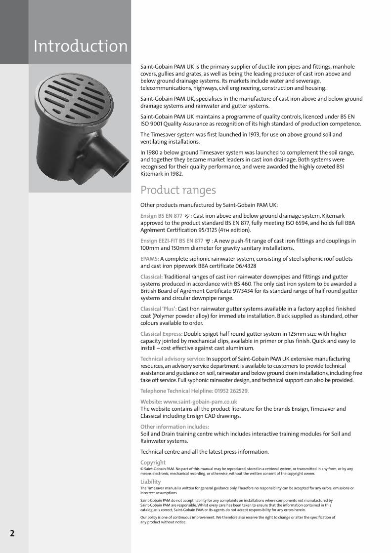
IntroductionSaint-Gobain PAM UK is the primary supplier of ductile iron pipes and fittings, manholecovers, gullies and grates, as well as being the leading producer of cast iron above andbelow ground drainage systems. Its markets include water and sewerage,telecommunications, highways, civil engineering, construction and housing.
Saint-Gobain PAM UK, specialises in the manufacture of cast iron above and below grounddrainage systems and rainwater and gutter systems.
Saint-Gobain PAM UK maintains a programme of quality controls, licenced under BS ENISO 9001Quality Assurance as recognition of its high standard of production competence.
The Timesaver system was first launched in 1973, for use on above ground soil andventilating installations.
In 1980 a below ground Timesaver system was launched to complement the soil range,and together they became market leaders in cast iron drainage. Both systems wererecognised for their quality performance, and were awarded the highly coveted BSIKitemark in 1982.
Product rangesOther products manufactured by Saint-Gobain PAM UK:
Ensign BS EN 877 : Cast iron above and below ground drainage system. Kitemarkapproved to the product standard BS EN 877, fully meeting ISO 6594, and holds full BBAAgrément Certification 95/3125 (4th edition).
Ensign EEZI-FIT BS EN 877 : A new push-fit range of cast iron fittings and couplings in100mm and 150mm diameter for gravity sanitary installations.
EPAMS:A complete siphonic rainwater system, consisting of steel siphonic roof outletsand cast iron pipework BBA certificate 06/4328
Classical: Traditional ranges of cast iron rainwater downpipes and fittings and guttersystems produced in accordance with BS 460. The only cast iron system to be awarded aBritish Board of Agrément Certificate 97/3434 for its standard range of half round guttersystems and circular downpipe range.
Classical ‘Plus’: Cast Iron rainwater gutter systems available in a factory applied finishedcoat (Polymer powder alloy) for immediate installation. Black supplied as standard, othercolours available to order.
Classical Express: Double spigot half round gutter system in 125mm size with highercapacity jointed by mechanical clips, available in primer or plus finish. Quick and easy toinstall – cost effective against cast aluminium.
Technical advisory service: In support of Saint-Gobain PAM UK extensive manufacturingresources, an advisory service department is available to customers to provide technicalassistance and guidance on soil, rainwater and below ground drain installations, including freetake off service. Full syphonic rainwater design, and technical support can also be provided.
Telephone Technical Helpline: 01952 262529.
Website: www.saint-gobain-pam.co.ukThe website contains all the product literature for the brands Ensign, Timesaver andClassical including Ensign CAD drawings.
Other information includes: Soil and Drain training centre which includes interactive training modules for Soil andRainwater systems.
Technical centre and all the latest press information.
Copyright© Saint-Gobain PAM. No part of this manual may be reproduced, stored in a retrieval system, or transmitted in any form, or by anymeans electronic, mechanical recording, or otherwise, without the written consent of the copyright owner.
LiabilityThe Timesaver manual is written for general guidance only. Therefore no responsibility can be accepted for any errors, omissions orincorrect assumptions.
Saint-Gobain PAM do not accept liability for any complaints on installations where components not manufactured by Saint-Gobain PAM are responsible. Whilst every care has been taken to ensure that the information contained in this catalogue is correct, Saint-Gobain PAM or its agents do not accept responsibility for any errors herein.
Our policy is one of continuous improvement. We therefore also reserve the right to change or alter the specification of any product without notice.
2
SGPL_119744_Timesaver Update 2012 Pages 1 to 40_REPRO_SF:Layout 1 30/04/2012 16:33 Page 2
Quality assuranceBS EN ISO 9001:2008 – Registered No: FM12908Products included in this manual are manufactured under the BS EN ISO 9001Quality Assurance Scheme.
Timesaver systems carry the BS Kitemark, providing the highest guarantee ofproduct quality, reliability and safety.
A strict quality control system is maintained throughout the company frompurchasing of raw materials to the inspection and testing of products.Spontaneous checks made throughout the year by the BSI Inspectorate, ensure thatthe set standards are not allowed to fall.
Kitemark licences can only be secured when quality control systems, as laid downin BS EN ISO 9001, have been implemented and approved by the BSI.
BS EN ISO 9001 legislates for Quality Assurance and may be chosen as analternative ‘third party guarantee’. It also provides a means of underwriting thequality of products which lie outside the scope of product standards such as BS 416 and BS 437.
On occasions, owing to pressure on normal production units, it may be necessary to manufacture certain components outside the confines of the BS EN ISO 9001Quality Assurance Licence. Such items will be produced, however, to a quality inkeeping with that of accredited manufacturing units.
Components so produced will be identified on the order acknowledgement.
3
Commitment to qualitySaint-Gobain PAM UK is committed to satisfying its customers’ needs in bothquality products and services.
It recognises the necessity for continual improvement in all disciplines throughoutthe organisation, and clearly states this objective to its employees at all levels.
As a basis for this objective, the company is committed to operating strict qualitymanagement systems in accordance with BS EN ISO 9001. It also recognises theresponsibility of the company’s employees in meeting the quality objectives and isconscious of their training and development needs.
Environment Standard BS EN ISO 14001: 2004Saint-Gobain PAM UK manufacturing sites, including Sinclair at Telford, have beenawarded the ‘Manufacturing to Environmental Standards’ accreditation BS EN ISO 14001: 2004 which was developed to help manufacturers maintain andimprove their management of environmental responsibilities and assist them inensuring compliance with environmental laws and regulations.
Saint-Gobain PAM UK operates Integrated Pollution and Preventative Control (IPPC)regulations, and have implemented comprehensive environmental managementsystems throughout its manufacturing sites.
CEMARS certification(Certified Emissions Measurement And Reduction Scheme)
Saint-Gobain PAM UK Ltd has been awarded certification to the world class, ISO-accredited CEMARS (Certified Emissions Measurement And Reduction Scheme)standard by the Achilles carbonReduction programme.
CEMARS certification demonstrates the company’s commitment to measuring,managing and reducing greenhouse gas emissions in a robust and credible way.
It confirms the company has measured its greenhouse gas emissions in compliancewith ISO 14064-1:2006 and has committed to managing and reducing its emissionsin respect of all operational activities across its Water & Sewer, Municipals and Soil& Drain business units.
Saint-Gobain PAM UK Ltd has achieved CEMARS for its operational carbon footprintfor the period 2011–2014.
Timesaver carries the covetedBritish Standard Kitemark forabove and below ground systems.
BS 416 Part 2For soil, waste and ventilatingpipes and fittingsBS 437For drain pipes and fittings BS 6087For flexible joints for BS 416 Part 2and BS 437 pipes and fittings
If customers have any doubts orqueries about the suitability of any Saint-Gobain PAM product, theyshould contact the Saint-GobainPAM UK Customer Service Unit on:0115 989 8066
Technical helpline:01952 262529
SGPL_119744_Timesaver Update 2012 Pages 1 to 40_REPRO_SF:Layout 1 30/04/2012 16:33 Page 3
Benefits of cast ironSuperior strength Exceptional crush resistance - vastly superior to other materialsl Timesaver BS437 150KN/ml Clay 40KN/ml PVC 6KN/ml The strongest soil and drain system – no contestl Exceptional crush resistance – vastly superior to HDPE and PVCl Exceptional resistance to over vigorous roddingl No. 1 choice for exposed areas ie. car parks, shopping centres, inner cities
– which are accessible to damage by accidental impact or vandalisml Used in areas where ground is unstable or the trenches are shallowl Less bedding required.
Non-combustible l Cast iron provides up to 4 hours fire integrityl Cast iron has no calorific values (ie. substances which actually fuel the fire)
and therefore will not assist the spread of firel Cast iron will not emit toxic fumes unlike PVC-u and sooty smog like HDPE,
which is often the cause of death during the first 30 minutes of a firel The cast iron system will not collapse under the intense heat, unlike PVC-u
and HDPE which can be life threatening to occupants and rescue teamsl No fire protection required when penetrating floors in accordance with
document B.
Noise reduction (the silent solution)l Cast iron is the quietest system with exceptional sound deadening
qualities (proven)l Tests carried out in a laboratory in Germany to BS EN 14366 show cast iron
up to 10dB(A) quieter than most other materials.
Sustainable (the environmental choice)l 100% recyclable – produced from virtually 100% recyclable scrapl Greenpeace recommended – no greater approbationl Cast iron should never be a candidate for landfilll Production creates no toxic wastel Best drainage solution on land reclamation sitesl Less bedding, less supports, less insulation – less is more when it comes to
safeguarding natural resourcesl Life time promise – not uncommon to exceed 100 years – minimal
environmental impact.
Ease of installationl Simple mechanical couplings or push-fit couplingsl No special tools like butt fusion machines needed to install HDPE at substantial
cost or rentall Installation cast iron has no added complications: fire collars/cladding,
additional brackets, sound insulation, expansion joints, thermal limiters etc.unlike PVC-u and HDPE.
Cost effectivel No. 1 choice for PFI projectsl Fit and forget – minimal maintenance for lease periodl Lifetime expectancyl Can often be the most cost effective option when total installed cost is measured,
expected maintenance required and a full risk assessment carried out – ie. theconsequential cost of failure in the system.
No expansion jointsl The coefficients of linear expansion for cast iron and concrete are almost identicall This makes cast iron a highly suitable material where drainage systems are
required to pierce concrete floor slabs
4
SGPL_119744_Timesaver Update 2012 Pages 1 to 40_REPRO_SF:Layout 1 30/04/2012 16:33 Page 4
Why specify Timesaver
Benefits of cast ironl No special jointing to allow for differential expansion is needed. In contrast,
PVC-u piping requires an expansion joint every 3m, as well as expensive thermal limiters.
Longevityl There are two elements of an above ground drainage system that should be
designed and specified to last the lifetime of the building:
1. the internal rainwater pipes
2. the soil discharge stacks
Even when a building is modernised every 15 or 20 years, these elements alongwith the structure will likely remain. If the toilet or kitchen area is refurbished, thebranch discharge pipes will often be renewed and therefore it may be appropriateto specify other materials for that element. But if the main stacks are to bespecified to last the lifetime of a building, perhaps 50-70 years or more, theappropriate material is mechanical jointed cast iron, for it is one of few materialsyou can reasonably fit and forget, as recognised by specifiers on many of the newPFI-type projects.
Proven drainage system for nearly 40 yearsThe Timesaver system, was first launched in 1973, for use on above ground soil andventilating installations.
In 1980 a below ground Timesaver system was launched to complement the soilrange, and together they became market leaders in cast iron drainage.
Both systems were recognised for their quality performance, and were awarded thehighly coveted BS Kitemark in 1982.
RefurbishmentPrestigious commercial buildings built in the 1970’s to the mid 90’s which areserviced by cast iron soil stacks, will most likely be Timesaver. If the building is to berefurbished and changes are required, the latest Timesaver range is best suited toconnect to the original pipework.
5
SGPL_119744_Timesaver Update 2012 Pages 1 to 40_REPRO_SF:Layout 1 30/04/2012 16:33 Page 5
Why specify TimesaverTimesaver Heritage couplings give traditional appearance The Timesaver range contains push-fit couplings that turns a mechanical pipesystem into a system with a traditional socket appearance of yesteryear, asdepicted in BS 416 Part 1.
Its primer black coating makes it easy to overpaint for external soil stacks, and is the perfect solution for listed buildings and those situated in areas ofconservation. Pipes are available in 3m lengths or in the traditional 1.8m (6ft)length, in 75 and 100mm diameter and by using the Timesaver Heritage couplings, waste is minimised and installation time, compared to the old socket/spigotcaulking method, is significantly reduced.
The Timesaver Heritage couplings have been accepted by recognised bodies for allgrade listed properties ie. National Heritage, English Heritage etc.
Strength Timesaver is recognised as the strongest of all the drainage systems in any material,in particular for below ground applications. The substantial section thickness of BS 437, makes it the first choice for under building drainage, especially oncommercial buildings where fit and forget is a high priority and provides peace of mind.
Also in areas where the drainage is to be installed in unstable ground, or groundcontaining methane gases, the strength of Timesaver puts it out on its own.
The above ground soil range with its increased section thickness, can providefurther strengths in areas where impact can occur ie. externally on the buildingfabric and car parks.
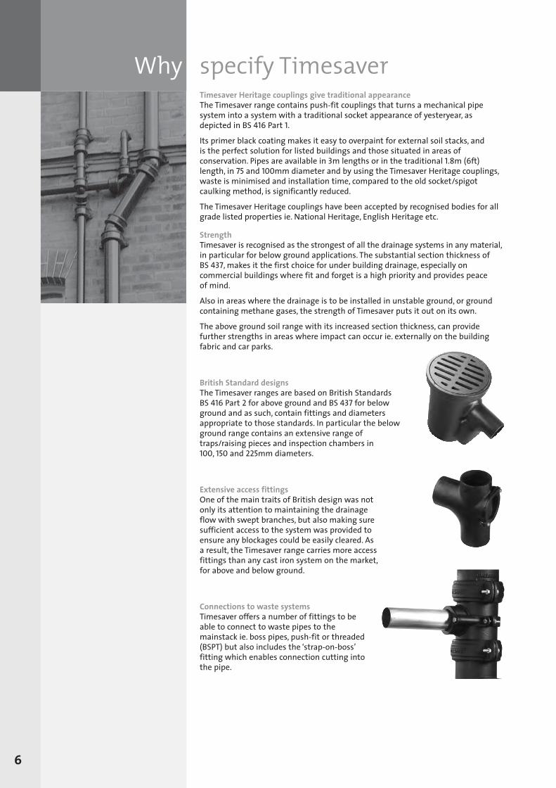
British Standard designsThe Timesaver ranges are based on British Standards BS 416 Part 2 for above ground and BS 437 for belowground and as such, contain fittings and diametersappropriate to those standards. In particular the belowground range contains an extensive range oftraps/raising pieces and inspection chambers in100, 150 and 225mm diameters.
Extensive access fittingsOne of the main traits of British design was notonly its attention to maintaining the drainageflow with swept branches, but also making suresufficient access to the system was provided toensure any blockages could be easily cleared. Asa result, the Timesaver range carries more accessfittings than any cast iron system on the market,for above and below ground.
Connections to waste systemsTimesaver offers a number of fittings to beable to connect to waste pipes to themainstack ie. boss pipes, push-fit or threaded(BSPT) but also includes the ‘strap-on-boss’fitting which enables connection cutting intothe pipe.
6
SGPL_119744_Timesaver Update 2012 Pages 1 to 40_REPRO_SF:Layout 1 30/04/2012 16:34 Page 6
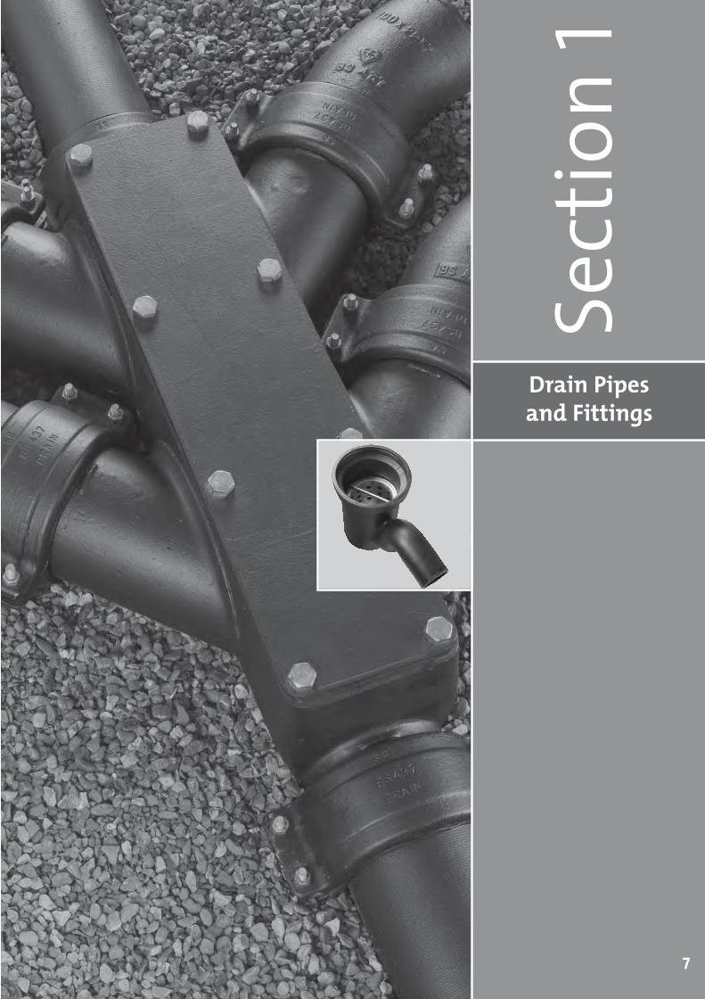
Drain Pipes and Fittings
Sect
ion 1
7
SGPL_119744_Timesaver Update 2012 Pages 1 to 40_REPRO_SF:Layout 1 30/04/2012 16:34 Page 7
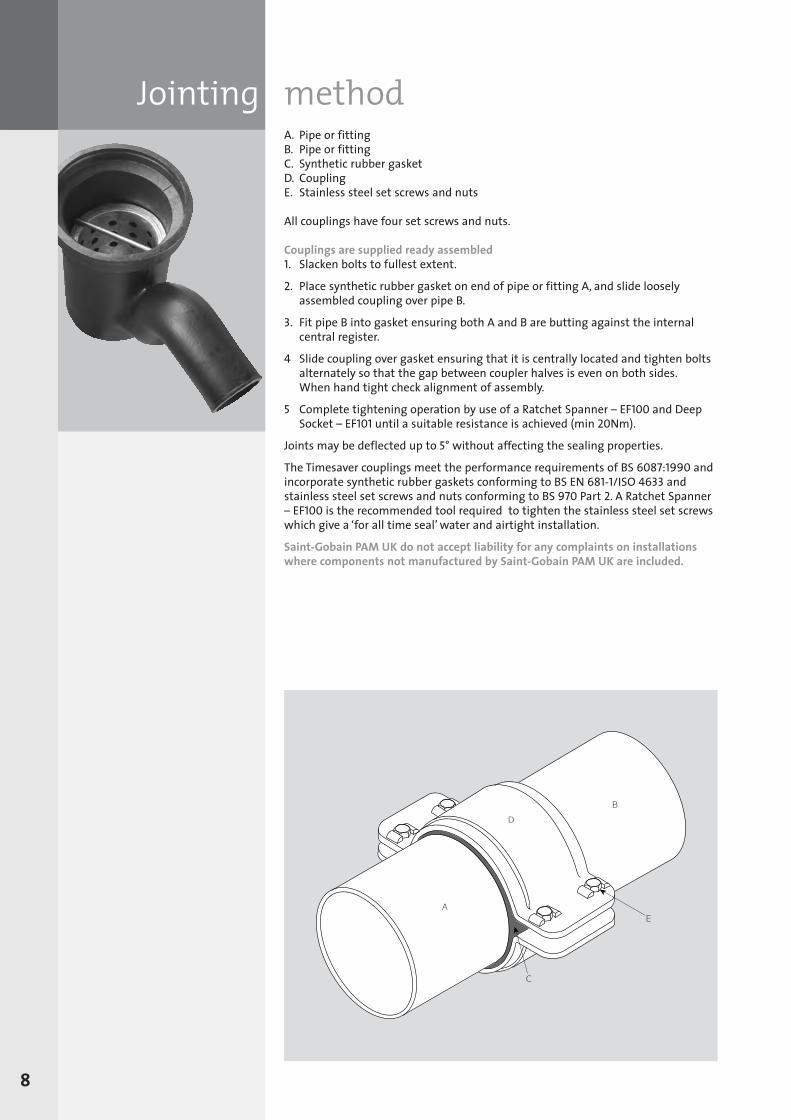
Jointing methodA. Pipe or fittingB. Pipe or fittingC. Synthetic rubber gasketD. CouplingE. Stainless steel set screws and nuts
All couplings have four set screws and nuts.
Couplings are supplied ready assembled1. Slacken bolts to fullest extent.
2. Place synthetic rubber gasket on end of pipe or fitting A, and slide looselyassembled coupling over pipe B.
3. Fit pipe B into gasket ensuring both A and B are butting against the internalcentral register.
4 Slide coupling over gasket ensuring that it is centrally located and tighten boltsalternately so that the gap between coupler halves is even on both sides. When hand tight check alignment of assembly.
5 Complete tightening operation by use of a Ratchet Spanner – EF100 and DeepSocket – EF101 until a suitable resistance is achieved (min 20Nm).
Joints may be deflected up to 5° without affecting the sealing properties.
The Timesaver couplings meet the performance requirements of BS 6087:1990 andincorporate synthetic rubber gaskets conforming to BS EN 681-1/ISO 4633 andstainless steel set screws and nuts conforming to BS 970 Part 2. A Ratchet Spanner– EF100 is the recommended tool required to tighten the stainless steel set screwswhich give a ‘for all time seal’ water and airtight installation.
Saint-Gobain PAM UK do not accept liability for any complaints on installationswhere components not manufactured by Saint-Gobain PAM UK are included.
8
SGPL_119744_Timesaver Update 2012 Pages 1 to 40_REPRO_SF:Layout 1 30/04/2012 16:34 Page 8
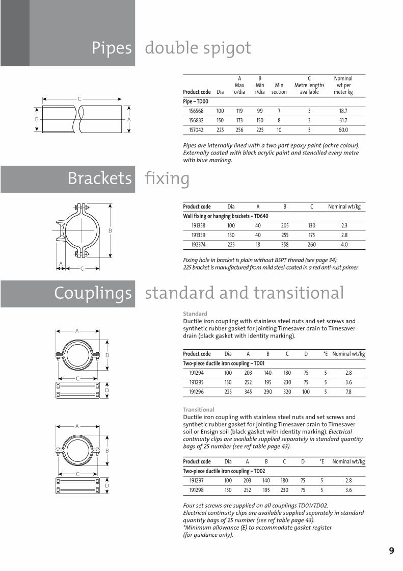
Brackets fixing
Couplings standard and transitional
Pipes double spigot
9
A B C Nominal Max Min Min Metre lengths wt per
Product code Dia o/dia i/dia section available meter kgPipe – TD00
156568 100 119 99 7 3 18.7156832 150 173 150 8 3 31.7157042 225 256 225 10 3 60.0
Pipes are internally lined with a two part epoxy paint (ochre colour).Externally coated with black acrylic paint and stencilled every metrewith blue marking.
Product code Dia A B C Nominal wt/kgWall fixing or hanging brackets – TD640
191358 100 40 205 130 2.3191359 150 40 255 175 2.8192374 225 18 358 260 4.0
Fixing hole in bracket is plain without BSPT thread (see page 34). 225 bracket is manufactured from mild steel-coated in a red anti-rust primer.
Product code Dia A B C D *E Nominal wt/kgTwo-piece ductile iron coupling – TD01
191294 100 203 140 180 75 5 2.8191295 150 252 195 230 75 5 3.6191296 225 345 290 320 100 5 7.8
StandardDuctile iron coupling with stainless steel nuts and set screws andsynthetic rubber gasket for jointing Timesaver drain to Timesaverdrain (black gasket with identity marking).
Product code Dia A B C D *E Nominal wt/kgTwo-piece ductile iron coupling – TD02
191297 100 203 140 180 75 5 2.8191298 150 252 195 230 75 5 3.6
Four set screws are supplied on all couplings TD01/TD02. Electrical continuity clips are available supplied separately in standardquantity bags of 25 number (see ref table page 43).*Minimum allowance (E) to accommodate gasket register (for guidance only).
TransitionalDuctile iron coupling with stainless steel nuts and set screws andsynthetic rubber gasket for jointing Timesaver drain to Timesaversoil or Ensign soil (black gasket with identity marking). Electricalcontinuity clips are available supplied separately in standard quantitybags of 25 number (see ref table page 43).
SGPL_119744_Timesaver Update 2012 Pages 1 to 40_REPRO_SF:Layout 1 30/04/2012 16:34 Page 9
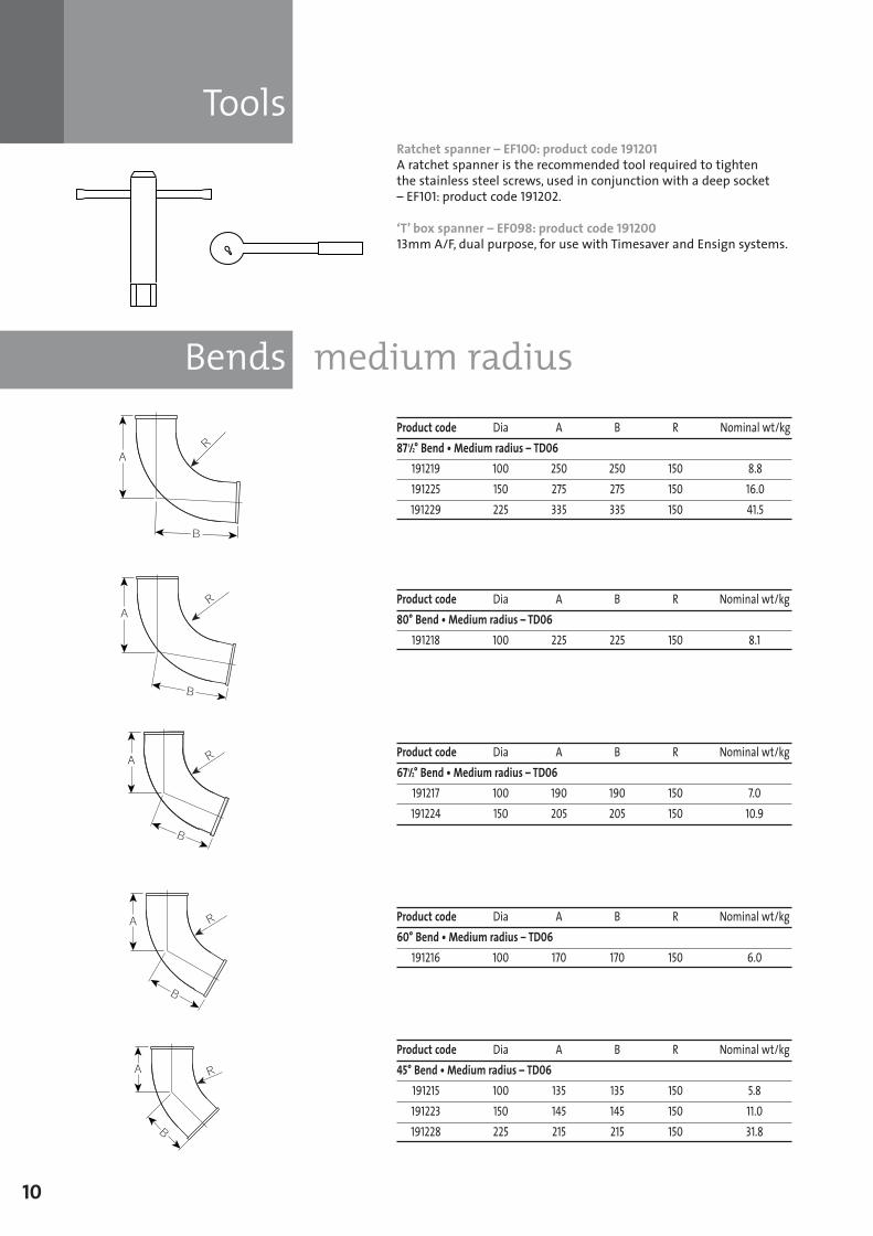
Tools
Bends medium radius
10
Ratchet spanner – EF100: product code 191201A ratchet spanner is the recommended tool required to tighten the stainless steel screws, used in conjunction with a deep socket – EF101: product code 191202.
‘T’ box spanner – EF098: product code 19120013mm A/F, dual purpose, for use with Timesaver and Ensign systems.
Product code Dia A B R Nominal wt/kg87 1/2° Bend • Medium radius – TD06
191219 100 250 250 150 8.8191225 150 275 275 150 16.0191229 225 335 335 150 41.5
Product code Dia A B R Nominal wt/kg671/2° Bend • Medium radius – TD06
191217 100 190 190 150 7.0191224 150 205 205 150 10.9
Product code Dia A B R Nominal wt/kg80° Bend • Medium radius – TD06
191218 100 225 225 150 8.1
Product code Dia A B R Nominal wt/kg60° Bend • Medium radius – TD06
191216 100 170 170 150 6.0
Product code Dia A B R Nominal wt/kg45° Bend • Medium radius – TD06
191215 100 135 135 150 5.8191223 150 145 145 150 11.0191228 225 215 215 150 31.8
SGPL_119744_Timesaver Update 2012 Pages 1 to 40_REPRO_SF:Layout 1 30/04/2012 16:34 Page 10
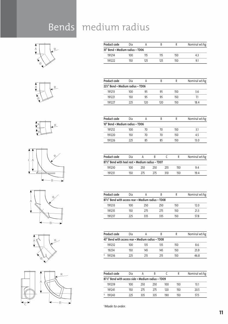
11
Product code Dia A B R Nominal wt/kg35° Bend • Medium radius – TD06
191214 100 115 115 150 4.3191222 150 125 125 150 9.1
Product code Dia A B R Nominal wt/kg221/2° Bend • Medium radius – TD06
191213 100 95 95 150 3.6191221 150 95 95 150 7.1191227 225 120 120 150 18.4
Product code Dia A B C R Nominal wt/kg871/2° Bend with heel rest • Medium radius – TD07
191230 100 250 250 255 150 9.4191231 150 275 275 310 150 19.4
Product code Dia A B R Nominal wt/kg10° Bend • Medium radius – TD06
191212 100 70 70 150 3.1191220 150 70 70 150 4.5191226 225 85 85 150 13.0
Product code Dia A B R Nominal wt/kg871/2° Bend with access rear • Medium radius – TD08
191233 100 250 250 150 12.0191235 150 275 275 150 21.3191237 225 335 335 150 57.8
Product code Dia A B R Nominal wt/kg45° Bend with access rear • Medium radius – TD08
191232 100 135 135 150 8.619234 150 145 145 150 25.9
† 191236 225 215 215 150 46.8
Product code Dia A B C R Nominal wt/kg87 1/2° Bend with access side • Medium radius – TD09
191239 100 250 250 100 150 13.1191241 150 275 275 120 150 20.5
† 191243 225 335 335 190 150 57.5
†Made to order.
Bends medium radius
SGPL_119744_Timesaver Update 2012 Pages 1 to 40_REPRO_SF:Layout 1 30/04/2012 16:34 Page 11
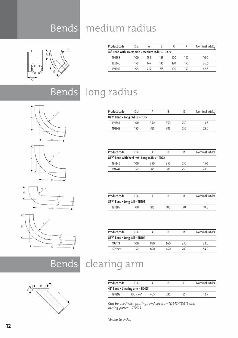
Bends medium radius
Bends long radius
Bends clearing arm
12
Product code Dia A B C R Nominal wt/kg45° Bend with access side • Medium radius – TD09
191238 100 135 135 100 150 10.0191240 150 145 145 120 150 26.6
† 191242 225 215 215 190 150 46.8
Product code Dia A B R Nominal wt/kg87 1/2° Bend • Long radius – TD15
191244 100 350 350 250 13.2191245 150 375 375 250 25.0
Product code Dia A B R Nominal wt/kg87 1/2° Bend • Long tail – TD102
191289 100 815 180 90 18.6
Product code Dia A B R Nominal wt/kg87 1/2° Bend • Long tail – TD104
197173 100 850 650 230 33.0192699 150 850 650 203 54.0
Product code Dia A B R Nominal wt/kg87 1/2° Bend with heel rest• Long radius – TD22
191246 100 350 350 250 15.0191247 150 375 375 250 28.0
†Made to order.
Product code Dia A B C Nominal wt/kg45° Bend • Clearing arm – TD425
191292 100 x 45° 405 235 35 12.5
Can be used with gratings and covers – TD612/TD616 and raising pieces – TD525.
SGPL_119744_Timesaver Update 2012 Pages 1 to 40_REPRO_SF:Layout 1 30/04/2012 16:34 Page 12
Branches
13†Made to order.
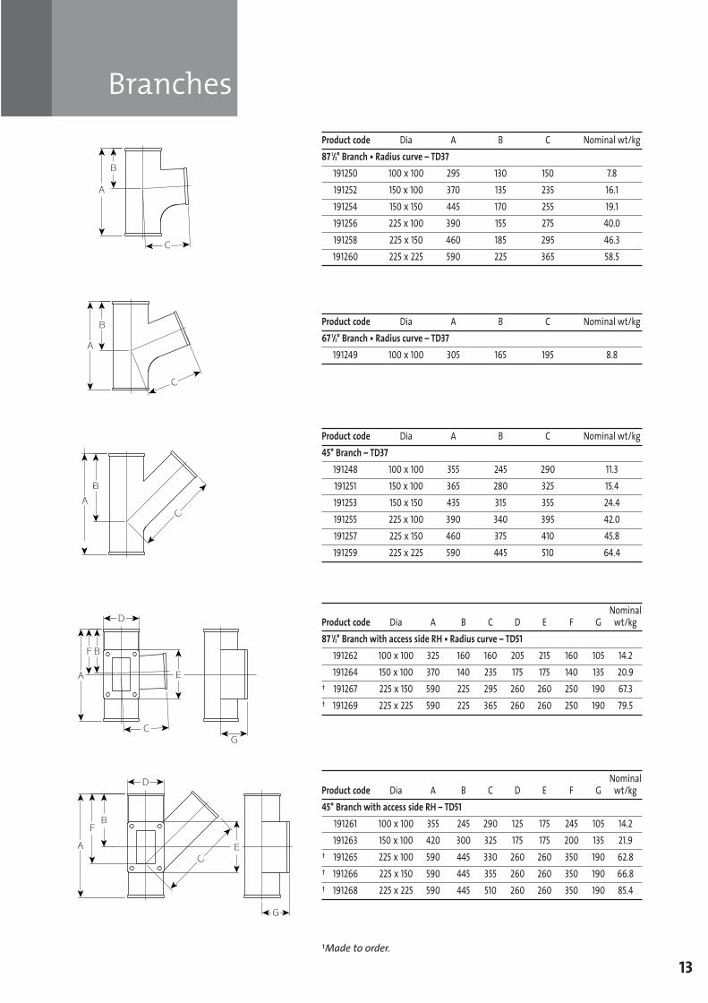
Product code Dia A B C Nominal wt/kg87 1/2° Branch • Radius curve – TD37
191250 100 x 100 295 130 150 7.8191252 150 x 100 370 135 235 16.1191254 150 x 150 445 170 255 19.1191256 225 x 100 390 155 275 40.0191258 225 x 150 460 185 295 46.3191260 225 x 225 590 225 365 58.5
Product code Dia A B C Nominal wt/kg45° Branch – TD37
191248 100 x 100 355 245 290 11.3191251 150 x 100 365 280 325 15.4191253 150 x 150 435 315 355 24.4191255 225 x 100 390 340 395 42.0191257 225 x 150 460 375 410 45.8191259 225 x 225 590 445 510 64.4
Product code Dia A B C Nominal wt/kg67 1/2° Branch • Radius curve – TD37
191249 100 x 100 305 165 195 8.8
Nominal Product code Dia A B C D E F G wt/kg87 1/2° Branch with access side RH • Radius curve – TD51
191262 100 x 100 325 160 160 205 215 160 105 14.2191264 150 x 100 370 140 235 175 175 140 135 20.9
† 191267 225 x 150 590 225 295 260 260 250 190 67.3† 191269 225 x 225 590 225 365 260 260 250 190 79.5
Nominal Product code Dia A B C D E F G wt/kg45° Branch with access side RH – TD51
191261 100 x 100 355 245 290 125 175 245 105 14.2191263 150 x 100 420 300 325 175 175 200 135 21.9
† 191265 225 x 100 590 445 330 260 260 350 190 62.8† 191266 225 x 150 590 445 355 260 260 350 190 66.8† 191268 225 x 225 590 445 510 260 260 350 190 85.4
SGPL_119744_Timesaver Update 2012 Pages 1 to 40_REPRO_SF:Layout 1 30/04/2012 16:34 Page 13
Branches
Branches double
14
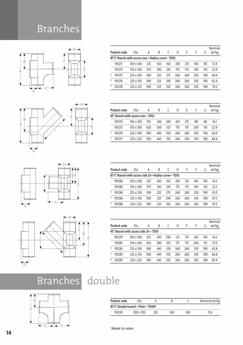
Nominal Product code Dia A B C D E F G wt/kg87 1/2° Branch with access rear • Radius curve – TD52
191271 100 x 100 325 160 160 205 215 160 80 13.4191273 150 x 100 370 140 235 175 175 140 110 22.9
† 191275 225 x 100 590 225 275 260 260 250 190 60.0† 191276 225 x 150 590 225 295 260 260 250 190 62.4† 191278 225 x 225 590 225 365 260 260 250 190 79.5
Nominal Product code Dia A B C D E F G wt/kg45° Branch with access rear – TD52
191270 100 x 100 355 240 290 205 215 185 80 16.1191272 150 x 100 420 300 325 175 175 200 110 22.9
† 191274 225 x 100 590 445 330 260 260 350 190 63.0† 191277 225 x 225 590 445 510 260 260 350 190 84.4
Nominal Product code Dia A B C D E F G wt/kg87 1/2° Branch with access side LH • Radius curve – TD53
191280 100 x 100 325 160 160 205 215 160 105 14.2191282 150 x 100 370 140 235 175 175 140 135 21.2
† 191284 225 x 100 590 225 275 260 260 250 190 61.0† 191286 225 x 150 590 225 295 260 260 250 190 67.3† 191288 225 x 225 590 225 365 260 260 250 190 79.5
Nominal Product code Dia A B C D E F G wt/kg45° Branch with access side LH – TD53
191279 100 x 100 355 245 290 125 175 245 105 14.2191281 150 x 100 365 280 325 175 175 200 135 21.9
† 191283 225 x 100 590 445 330 260 260 350 190 62.8† 191285 225 x 150 590 445 355 260 260 350 190 66.8† 191287 225 x 225 590 445 510 260 260 350 190 85.4
†Made to order.
Product code Dia A B C Nominal wt/kg87 1/2° Double branch • Plain – TD447
191293 100 x 100 325 160 160 11.6
SGPL_119744_Timesaver Update 2012 Pages 1 to 40_REPRO_SF:Layout 1 30/04/2012 16:34 Page 14
Pipes taper
Socket ferrules
Blank ends
Pipes access
15
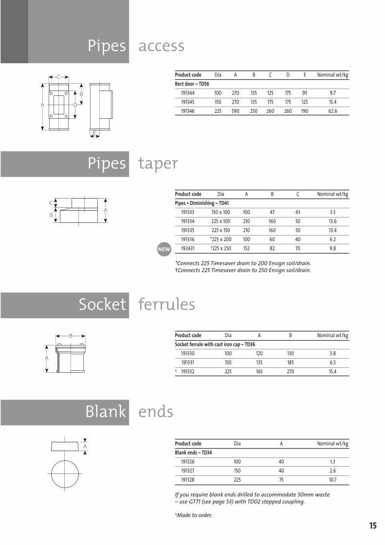
Product code Dia A B C D E Nominal wt/kgRect door – TD56
191344 100 270 135 125 175 95 9.7191345 150 270 135 175 175 125 15.4191346 225 590 250 260 260 190 62.6
Product code Dia A B C Nominal wt/kgPipes • Diminishing – TD41
191333 150 x 100 100 47 43 3.5191334 225 x 100 210 160 50 13.6191335 225 x 150 210 160 50 13.4191336 *225 x 200 100 60 40 6.2192431 †225 x 250 152 82 70 9.8
*Connects 225 Timesaver drain to 200 Ensign soil/drain.†Connects 225 Timesaver drain to 250 Ensign soil/drain.
Product code Dia A B Nominal wt/kgSocket ferrule with cast iron cap – TD36
191330 100 120 130 3.8191331 150 135 185 6.5
† 191332 225 165 270 15.4
†Made to order.
Product code Dia A Nominal wt/kgBlank ends – TD34
191326 100 40 1.3191327 150 40 2.6191328 225 75 10.7
If you require blank ends drilled to accommodate 50mm waste – use GT71 (see page 53) with TD02 stepped coupling.
NEW
SGPL_119744_Timesaver Update 2012 Pages 1 to 40_REPRO_SF:Layout 1 30/04/2012 16:34 Page 15
Pipes transitional
Gully traps
16
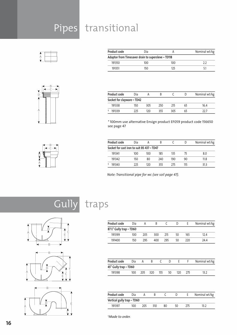
Product code Dia A Nominal wt/kgAdaptor from Timesaver drain to supersleve – TD118
191350 100 100 2.2191351 150 125 5.1
Product code Dia A B C D Nominal wt/kgSocket for clayware – TD42
191338 150 305 250 215 65 16.4† 191339 225 120 355 305 65 22.7
Product code Dia A B C D Nominal wt/kgSocket for cast iron to suit BS 437 – TD47
191341 100 100 185 135 75 8.0191342 150 80 240 190 90 11.8
† 191343 225 120 355 275 115 31.3
†Made to order.
Product code Dia A B C D E Nominal wt/kg87 1/2° Gully trap – TD60
191399 100 205 300 215 50 165 12.4191400 150 295 400 295 50 220 24.4
Product code Dia A B C D E F Nominal wt/kg45° Gully trap – TD60
191398 100 205 320 155 50 120 275 13.2
Product code Dia A B C D E Nominal wt/kgVertical gully trap – TD60
191397 100 205 310 80 50 275 13.2
Note: Transitional pipe for wc (see soil page 47).
* 100mm use alternative Ensign product EF059 product code 156650see page 47
SGPL_119744_Timesaver Update 2012 Pages 1 to 40_REPRO_SF:Layout 1 30/04/2012 16:34 Page 16
Gully inlets bellmouth
Gully traps
17
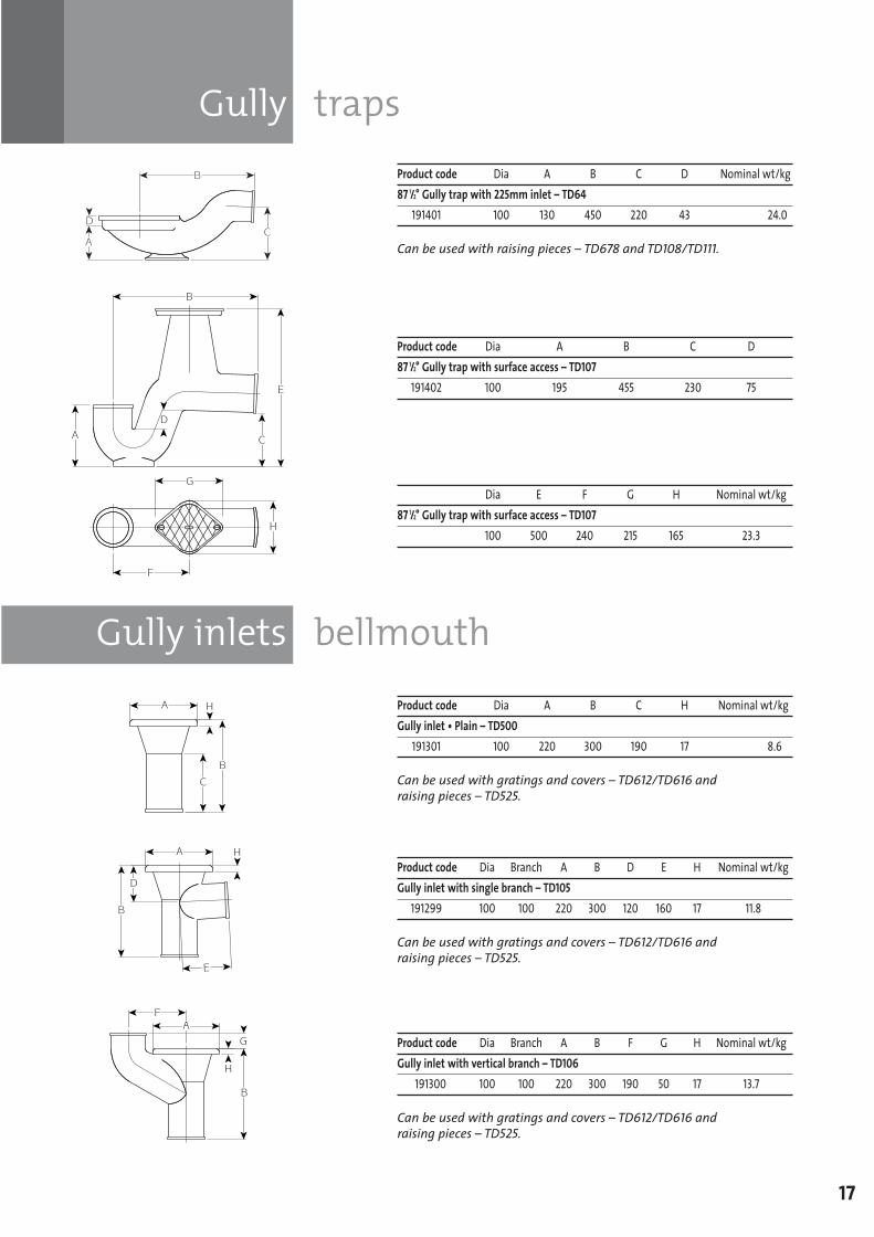
Product code Dia A B C D Nominal wt/kg87 1/2° Gully trap with 225mm inlet – TD64
191401 100 130 450 220 43 24.0
Can be used with raising pieces – TD678 and TD108/TD111.
Product code Dia A B C D87 1/2° Gully trap with surface access – TD107
191402 100 195 455 230 75
Dia E F G H Nominal wt/kg87 1/2° Gully trap with surface access – TD107
100 500 240 215 165 23.3
Product code Dia A B C H Nominal wt/kgGully inlet • Plain – TD500
191301 100 220 300 190 17 8.6
Can be used with gratings and covers – TD612/TD616 and raising pieces – TD525.
Product code Dia Branch A B D E H Nominal wt/kgGully inlet with single branch – TD105
191299 100 100 220 300 120 160 17 11.8
Can be used with gratings and covers – TD612/TD616 and raising pieces – TD525.
Product code Dia Branch A B F G H Nominal wt/kgGully inlet with vertical branch – TD106
191300 100 100 220 300 190 50 17 13.7
Can be used with gratings and covers – TD612/TD616 and raising pieces – TD525.
SGPL_119744_Timesaver Update 2012 Pages 1 to 40_REPRO_SF:Layout 1 30/04/2012 16:34 Page 17
Raising pieces
Gratings and covers
18
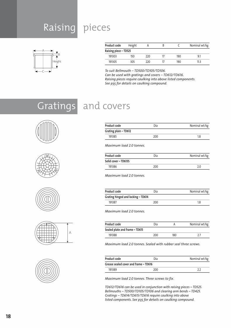
Product code Height A B C Nominal wt/kgRaising piece – TD525
191303 150 220 17 190 9.1191305 305 220 17 190 11.3
To suit Bellmouth – TD500/TD105/TD106.Can be used with gratings and covers – TD612/TD616.Raising pieces require caulking into above listed components.See p35 for details on caulking compound.
Product code Dia Nominal wt/kgGrating plain – TD612
191385 200 1.8
Maximum load 2.0 tonnes.
Product code Dia Nominal wt/kgSolid cover – TD613S
191386 200 2.0
Maximum load 2.0 tonnes.
Product code Dia Nominal wt/kgGrating hinged and locking – TD614
191387 200 1.8
Maximum load 2.0 tonnes.
Product code Dia A Nominal wt/kgSealed plate and frame – TD615
191388 200 180 2.7
Maximum load 2.0 tonnes. Sealed with rubber seal three screws.
Product code Dia Nominal wt/kgGrease sealed cover and frame – TD616
191389 200 2.2
Maximum load 2.0 tonnes. Three screws to fix.
TD612/TD616 can be used in conjunction with raising pieces – TD525.Bellmouths – TD500/TD105/TD106 and clearing arm bends – TD425.Gratings – TD614/TD615/TD616 require caulking into above listed components. See p35 for details on caulking compound.
SGPL_119744_Timesaver Update 2012 Pages 1 to 40_REPRO_SF:Layout 1 30/04/2012 16:34 Page 18
Gully traps
19
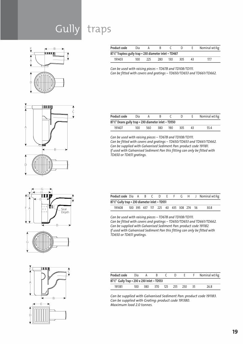
Product code Dia A B C D E Nominal wt/kg87 1/2° Trapless gully trap • 230 diameter inlet – TD467
191403 100 225 280 130 305 43 17.7
Can be used with raising pieces – TD678 and TD108/TD111.Can be fitted with covers and gratings – TD650/TD653 and TD661/TD662.
Product code Dia A B C D E Nominal wt/kg87 1/2° Deans gully trap • 230 diameter inlet – TD550
191407 100 560 380 190 305 43 55.4
Can be used with raising pieces – TD678 and TD108/TD111.Can be fitted with covers and gratings – TD650/TD653 and TD661/TD662.Can be supplied with Galvanised Sediment Pan: product code 191181.If used with Galvanised Sediment Pan this fitting can only be fitted withTD650 or TD651 gratings.
Product code Dia A B C D E F G H J Nominal wt/kg87 1/2° Gully trap • 230 diameter inlet – TD551
191408 100 395 437 117 225 40 435 308 274 56 30.8
Can be used with raising pieces – TD678 and TD108/TD111.Can be fitted with covers and gratings – TD650/TD653 and TD661/TD662.Can be supplied with Galvanised Sediment Pan: product code 191182.If used with Galvanised Sediment Pan this fitting can only be fitted withTD650 or TD651 gratings.
Product code Dia A B C D E F Nominal wt/kg87 1/2° Gully Trap • 230 x 230 Inlet – TD553
191381 100 380 370 125 255 250 35 26.8
Can be supplied with Galvanised Sediment Pan: product code 191183.Can be supplied with Grating: product code 191380. Maximum load 2.0 tonnes.
SGPL_119744_Timesaver Update 2012 Pages 1 to 40_REPRO_SF:Layout 1 30/04/2012 16:34 Page 19
20
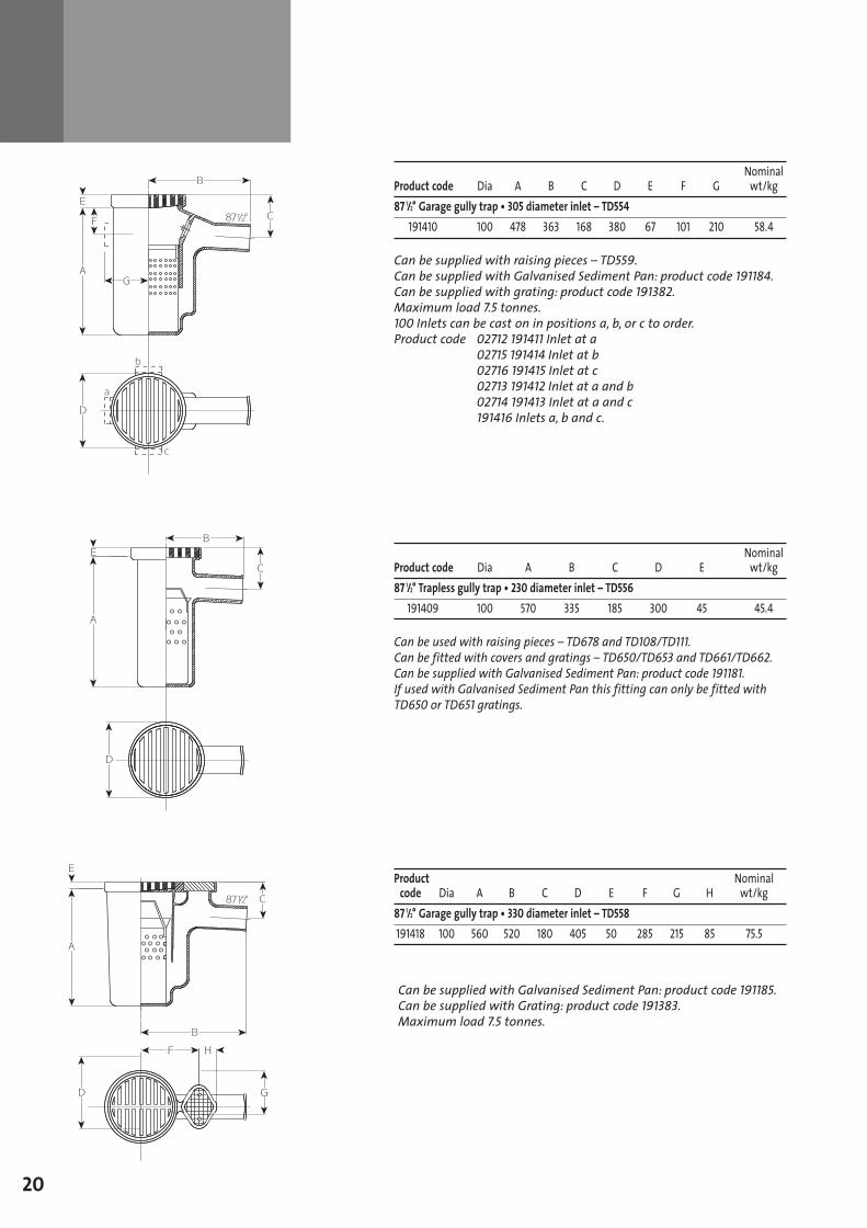
Nominal Product code Dia A B C D E F G wt/kg87 1/2° Garage gully trap • 305 diameter inlet – TD554
191410 100 478 363 168 380 67 101 210 58.4
Can be supplied with raising pieces – TD559.Can be supplied with Galvanised Sediment Pan: product code 191184.Can be supplied with grating: product code 191382. Maximum load 7.5 tonnes.100 Inlets can be cast on in positions a, b, or c to order.Product code 02712 191411 Inlet at a
02715 191414 Inlet at b 02716 191415 Inlet at c 02713 191412 Inlet at a and b 02714 191413 Inlet at a and c 191416 Inlets a, b and c.
Nominal Product code Dia A B C D E wt/kg87 1/2° Trapless gully trap • 230 diameter inlet – TD556
191409 100 570 335 185 300 45 45.4
Can be used with raising pieces – TD678 and TD108/TD111.Can be fitted with covers and gratings – TD650/TD653 and TD661/TD662.Can be supplied with Galvanised Sediment Pan: product code 191181.If used with Galvanised Sediment Pan this fitting can only be fitted withTD650 or TD651 gratings.
Product Nominalcode Dia A B C D E F G H wt/kg
87 1/2° Garage gully trap • 330 diameter inlet – TD558191418 100 560 520 180 405 50 285 215 85 75.5
Can be supplied with Galvanised Sediment Pan: product code 191185.Can be supplied with Grating: product code 191383. Maximum load 7.5 tonnes.
SGPL_119744_Timesaver Update 2012 Pages 1 to 40_REPRO_SF:Layout 1 30/04/2012 16:34 Page 20
Running traps
Raising pieces
Yard gully
21
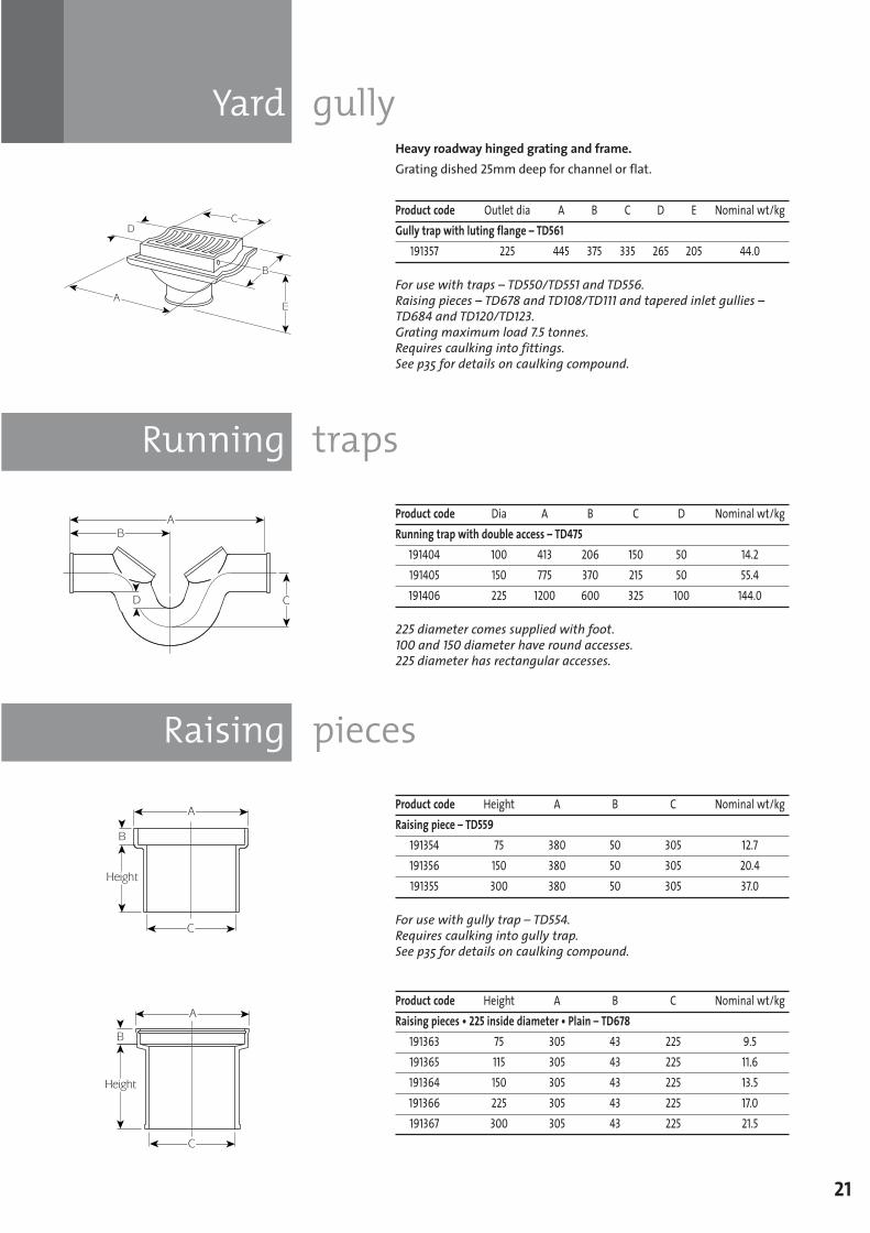
Heavy roadway hinged grating and frame.Grating dished 25mm deep for channel or flat.
Product code Outlet dia A B C D E Nominal wt/kgGully trap with luting flange – TD561
191357 225 445 375 335 265 205 44.0
For use with traps – TD550/TD551 and TD556. Raising pieces – TD678 and TD108/TD111 and tapered inlet gullies –TD684 and TD120/TD123.Grating maximum load 7.5 tonnes.Requires caulking into fittings. See p35 for details on caulking compound.
Product code Dia A B C D Nominal wt/kgRunning trap with double access – TD475
191404 100 413 206 150 50 14.2191405 150 775 370 215 50 55.4191406 225 1200 600 325 100 144.0
225 diameter comes supplied with foot.100 and 150 diameter have round accesses.225 diameter has rectangular accesses.
Product code Height A B C Nominal wt/kgRaising piece – TD559
191354 75 380 50 305 12.7191356 150 380 50 305 20.4191355 300 380 50 305 37.0
For use with gully trap – TD554.Requires caulking into gully trap.See p35 for details on caulking compound.
Product code Height A B C Nominal wt/kgRaising pieces • 225 inside diameter • Plain – TD678
191363 75 305 43 225 9.5191365 115 305 43 225 11.6191364 150 305 43 225 13.5191366 225 305 43 225 17.0191367 300 305 43 225 21.5
SGPL_119744_Timesaver Update 2012 Pages 1 to 40_REPRO_SF:Layout 1 30/04/2012 16:34 Page 21
Raising pieces
Tapered gully inlets
22
TD108/111
TD108
TD111
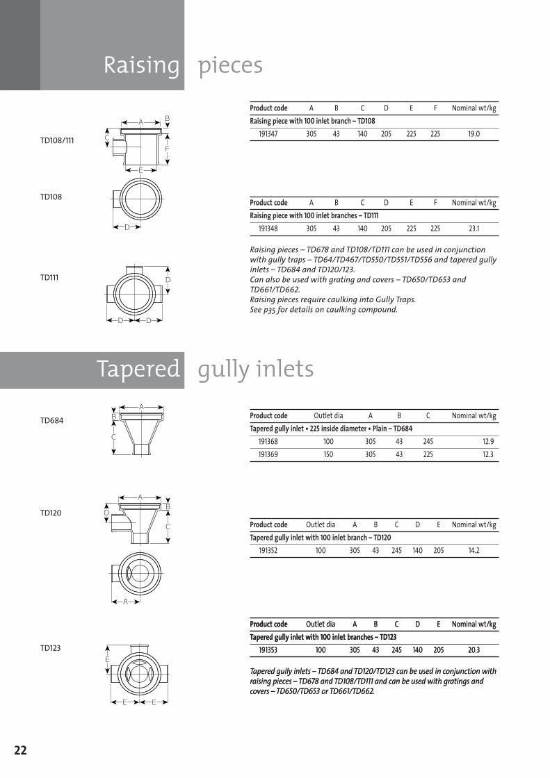
Product code A B C D E F Nominal wt/kgRaising piece with 100 inlet branch – TD108
191347 305 43 140 205 225 225 19.0
Product code A B C D E F Nominal wt/kgRaising piece with 100 inlet branches – TD111
191348 305 43 140 205 225 225 23.1
Raising pieces – TD678 and TD108/TD111 can be used in conjunctionwith gully traps – TD64/TD467/TD550/TD551/TD556 and tapered gullyinlets – TD684 and TD120/123.Can also be used with grating and covers – TD650/TD653 andTD661/TD662.Raising pieces require caulking into Gully Traps.See p35 for details on caulking compound.
Product code Outlet dia A B C D E Nominal wt/kgTapered gully inlet with 100 inlet branch – TD120
191352 100 305 43 245 140 205 14.2
Product code Outlet dia A B C Nominal wt/kgTapered gully inlet • 225 inside diameter • Plain – TD684
191368 100 305 43 245 12.9191369 150 305 43 225 12.3
Product code Outlet dia A B C D E Nominal wt/kgTapered gully inlet with 100 inlet branches – TD123
191353 100 305 43 245 140 205 20.3
Tapered gully inlets – TD684 and TD120/TD123 can be used in conjunction withraising pieces – TD678 and TD108/TD111 and can be used with gratings andcovers – TD650/TD653 or TD661/TD662.
TD684
TD120
TD123
SGPL_119744_Timesaver Update 2012 Pages 1 to 40_REPRO_SF:Layout 1 30/04/2012 16:34 Page 22
Gratings and covers
23
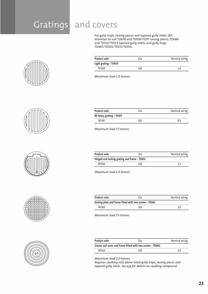
For gully traps, raising pieces and tapered gully inlets 265diameter to suit TD678 and TD108/TD111 raising pieces, TD684and TD120/TD123 tapered gully inlets, and gully trapsTD467/TD550/TD551/TD556.
Product code Dia Nominal wt/kgLight grating – TD650
191390 265 3.6
Maximum load 2.0 tonnes.
Product code Dia Nominal wt/kgBS heavy grating – TD651
191391 265 8.0
Maximum load 7.5 tonnes.
Product code Dia Nominal wt/kgHinged and locking grating and frame – TD653
191360 265 5.3
Maximum load 2.0 tonnes.
Product code Dia Nominal wt/kgSealing plate and frame fitted with two screws – TD661
191361 265 5.0
Maximum load 7.5 tonnes.
Product code Dia Nominal wt/kgGrease seal cover and frame fitted with two screws – TD662
191362 265 3.6
Maximum load 2.0 tonnes.Requires caulking into above listed gully traps, raising pieces andtapered gully inlets. See p35 for details on caulking compound.
SGPL_119744_Timesaver Update 2012 Pages 1 to 40_REPRO_SF:Layout 1 30/04/2012 16:34 Page 23
Rainwater shoes
Raising pieces
Gratings and covers
24
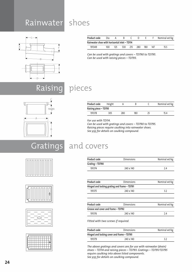
Product code Dia A B C D E F Nominal wt/kgRainwater shoe with horizontal inlet – TD114
191349 100 125 530 215 280 180 147 15.5
Can be used with gratings and covers – TD790 to TD795.Can be used with raising pieces – TD793.
Product code Height A B C Nominal wt/kgRaising piece – TD793
191378 305 280 180 25 15.4
For use with TD114.Can be used with gratings and covers – TD790 to TD795.Raising pieces require caulking into rainwater shoes.See p35 for details on caulking compound.
Product code Dimensions Nominal wt/kgGrating – TD790
191374 240 x 140 2.4
Product code Dimensions Nominal wt/kgHinged and locking grating and frame – TD791
191375 240 x 140 3.2
Product code Dimensions Nominal wt/kgGrease seal cover and frame – TD792
191376 240 x 140 2.4
Fitted with two screws if required.
Product code Dimensions Nominal wt/kgHinged and locking cover and frame – TD795
191379 240 x 140 3.2
The above gratings and covers are for use with rainwater (drain)shoes – TD114 and raising pieces – TD793. Gratings – TD791/TD795require caulking into above listed components. See p35 for details on caulking compound.
SGPL_119744_Timesaver Update 2012 Pages 1 to 40_REPRO_SF:Layout 1 30/04/2012 16:34 Page 24
Chambers
Airtight inspection eye covers
25
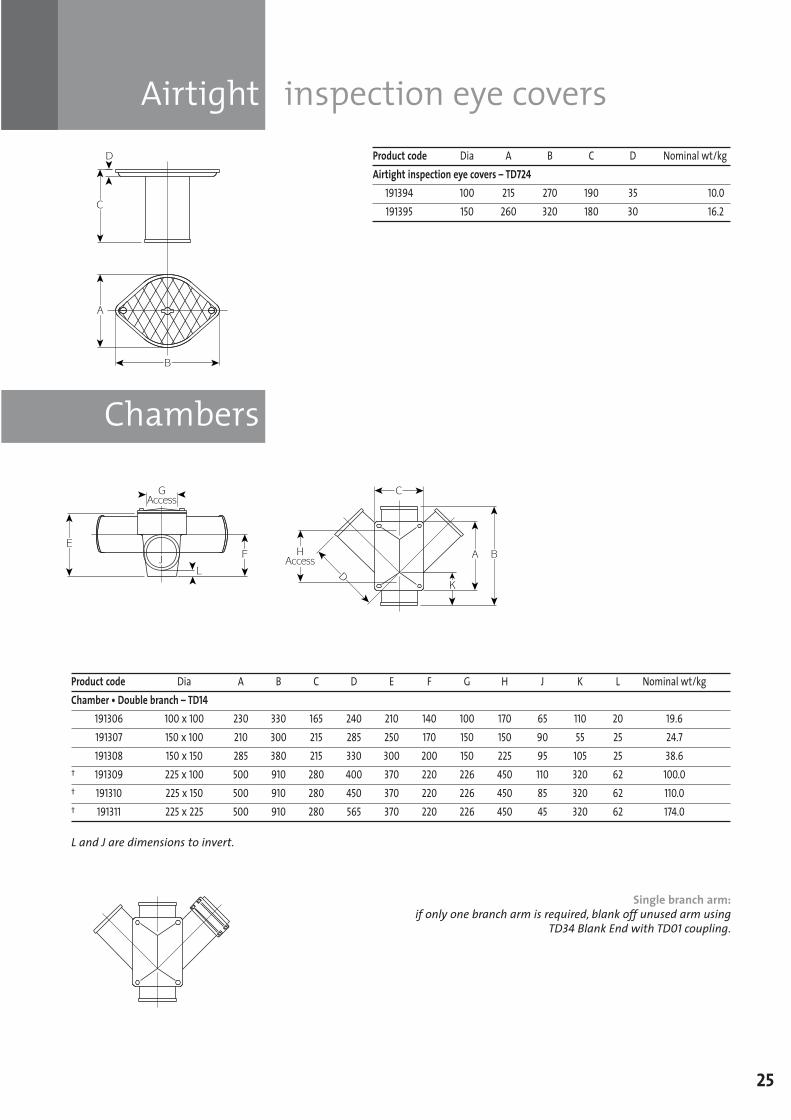
Product code Dia A B C D Nominal wt/kgAirtight inspection eye covers – TD724
191394 100 215 270 190 35 10.0191395 150 260 320 180 30 16.2
Product code Dia A B C D E F G H J K L Nominal wt/kgChamber • Double branch – TD14
191306 100 x 100 230 330 165 240 210 140 100 170 65 110 20 19.6191307 150 x 100 210 300 215 285 250 170 150 150 90 55 25 24.7191308 150 x 150 285 380 215 330 300 200 150 225 95 105 25 38.6
† 191309 225 x 100 500 910 280 400 370 220 226 450 110 320 62 100.0† 191310 225 x 150 500 910 280 450 370 220 226 450 85 320 62 110.0† 191311 225 x 225 500 910 280 565 370 220 226 450 45 320 62 174.0
L and J are dimensions to invert.
Single branch arm:if only one branch arm is required, blank off unused arm using
TD34 Blank End with TD01 coupling.
SGPL_119744_Timesaver Update 2012 Pages 1 to 40_REPRO_SF:Layout 1 30/04/2012 16:34 Page 25
26
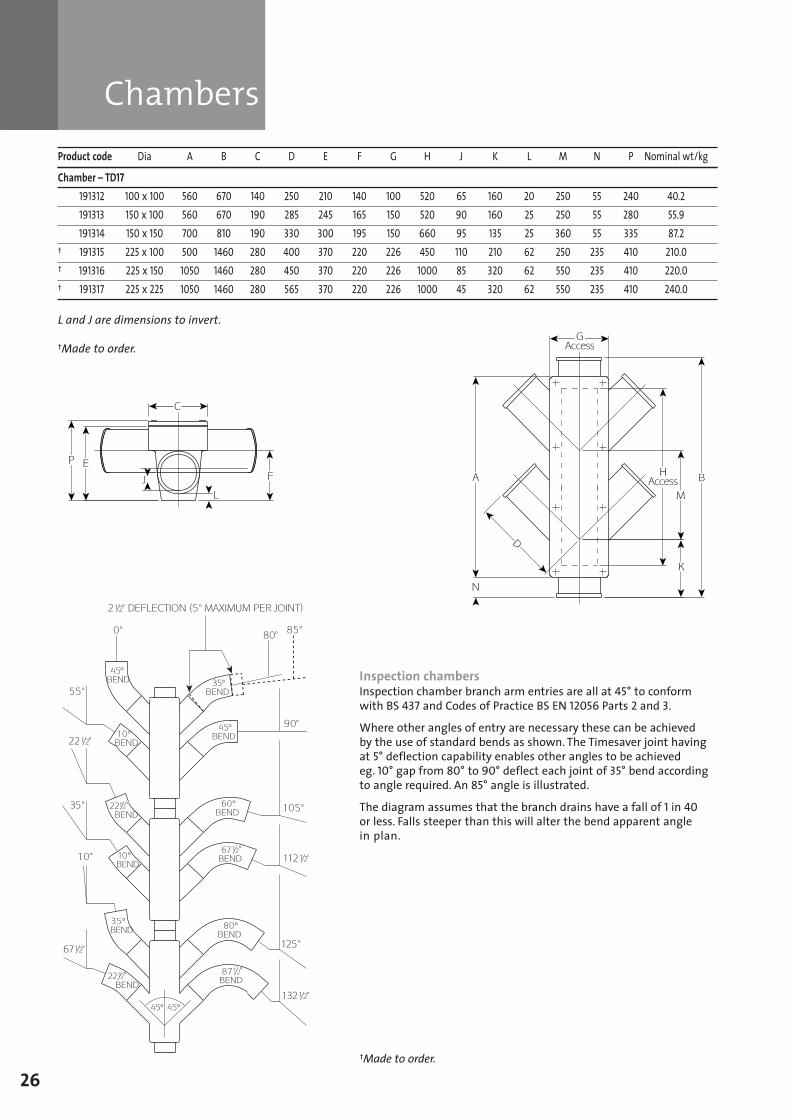
Product code Dia A B C D E F G H J K L M N P Nominal wt/kg
Chamber – TD17191312 100 x 100 560 670 140 250 210 140 100 520 65 160 20 250 55 240 40.2191313 150 x 100 560 670 190 285 245 165 150 520 90 160 25 250 55 280 55.9191314 150 x 150 700 810 190 330 300 195 150 660 95 135 25 360 55 335 87.2
† 191315 225 x 100 500 1460 280 400 370 220 226 450 110 210 62 250 235 410 210.0† 191316 225 x 150 1050 1460 280 450 370 220 226 1000 85 320 62 550 235 410 220.0† 191317 225 x 225 1050 1460 280 565 370 220 226 1000 45 320 62 550 235 410 240.0
L and J are dimensions to invert.
†Made to order.
A
†Made to order.
Inspection chambersInspection chamber branch arm entries are all at 45° to conformwith BS 437 and Codes of Practice BS EN 12056 Parts 2 and 3.
Where other angles of entry are necessary these can be achieved by the use of standard bends as shown. The Timesaver joint havingat 5° deflection capability enables other angles to be achieved eg. 10° gap from 80° to 90° deflect each joint of 35° bend accordingto angle required. An 85° angle is illustrated.
The diagram assumes that the branch drains have a fall of 1 in 40or less. Falls steeper than this will alter the bend apparent angle in plan.
Chambers
SGPL_119744_Timesaver Update 2012 Pages 1 to 40_REPRO_SF:Layout 1 30/04/2012 16:34 Page 26
Ball valve anti-flooding
Eureka anti-flooding trunk valves
27
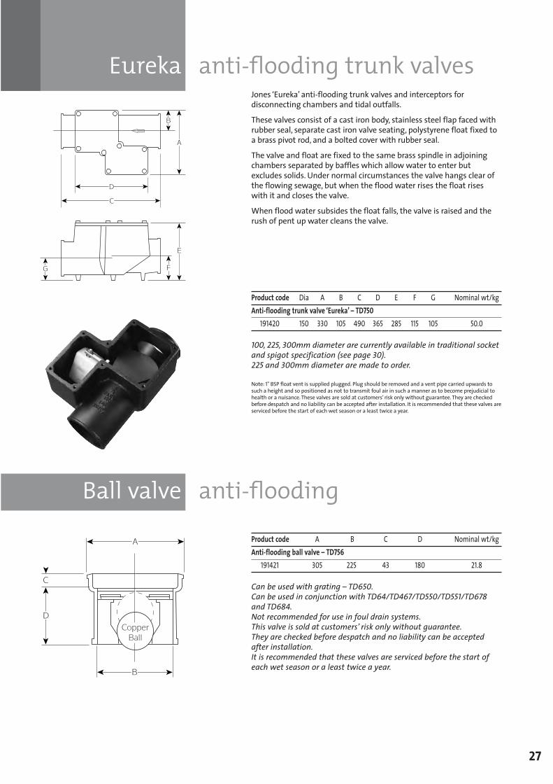
Product code Dia A B C D E F G Nominal wt/kgAnti-flooding trunk valve ‘Eureka’ – TD750
191420 150 330 105 490 365 285 115 105 50.0
100, 225, 300mm diameter are currently available in traditional socketand spigot specification (see page 30). 225 and 300mm diameter are made to order.
Note: 1" BSP float vent is supplied plugged. Plug should be removed and a vent pipe carried upwards tosuch a height and so positioned as not to transmit foul air in such a manner as to become prejudicial tohealth or a nuisance. These valves are sold at customers’ risk only without guarantee. They are checkedbefore despatch and no liability can be accepted after installation. It is recommended that these valves areserviced before the start of each wet season or a least twice a year.
Jones ‘Eureka’ anti-flooding trunk valves and interceptors fordisconnecting chambers and tidal outfalls.
These valves consist of a cast iron body, stainless steel flap faced withrubber seal, separate cast iron valve seating, polystyrene float fixed toa brass pivot rod, and a bolted cover with rubber seal.
The valve and float are fixed to the same brass spindle in adjoiningchambers separated by baffles which allow water to enter butexcludes solids. Under normal circumstances the valve hangs clear ofthe flowing sewage, but when the flood water rises the float riseswith it and closes the valve.
When flood water subsides the float falls, the valve is raised and therush of pent up water cleans the valve.
Product code A B C D Nominal wt/kgAnti-flooding ball valve – TD756
191421 305 225 43 180 21.8
Can be used with grating – TD650. Can be used in conjunction with TD64/TD467/TD550/TD551/TD678and TD684. Not recommended for use in foul drain systems. This valve is sold at customers’ risk only without guarantee. They are checked before despatch and no liability can be acceptedafter installation. It is recommended that these valves are serviced before the start ofeach wet season or a least twice a year.
SGPL_119744_Timesaver Update 2012 Pages 1 to 40_REPRO_SF:Layout 1 30/04/2012 16:34 Page 27
Flanges loose puddle
Grease traps
28
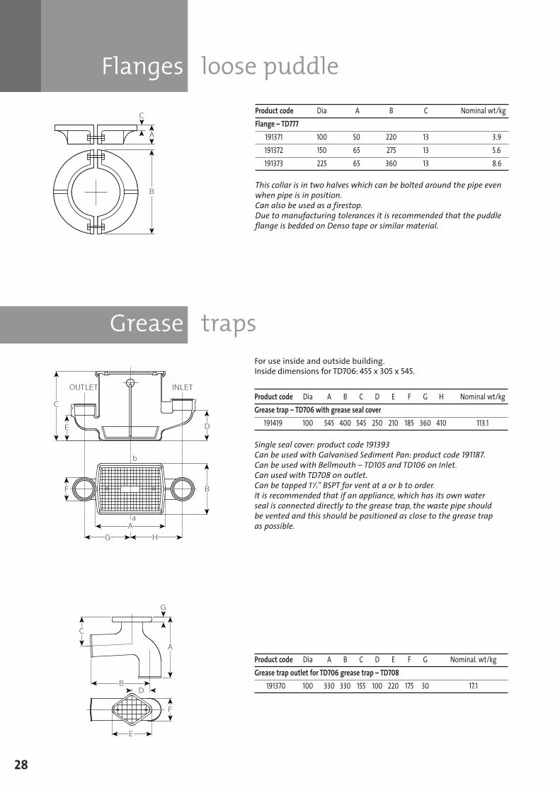
Product code Dia A B C Nominal wt/kgFlange – TD777
191371 100 50 220 13 3.9191372 150 65 275 13 5.6191373 225 65 360 13 8.6
This collar is in two halves which can be bolted around the pipe evenwhen pipe is in position.Can also be used as a firestop.Due to manufacturing tolerances it is recommended that the puddleflange is bedded on Denso tape or similar material.
For use inside and outside building.Inside dimensions for TD706: 455 x 305 x 545.
Product code Dia A B C D E F G H Nominal wt/kgGrease trap – TD706 with grease seal cover
191419 100 545 400 545 250 210 185 360 410 113.1
Single seal cover: product code 191393Can be used with Galvanised Sediment Pan: product code 191187.Can be used with Bellmouth – TD105 and TD106 on Inlet.Can used with TD708 on outlet.Can be tapped 1 1/2" BSPT for vent at a or b to order.It is recommended that if an appliance, which has its own water seal is connected directly to the grease trap, the waste pipe should be vented and this should be positioned as close to the grease trap as possible.
Product code Dia A B C D E F G Nominal. wt/kgGrease trap outlet for TD706 grease trap – TD708
191370 100 330 330 155 100 220 175 30 17.1
SGPL_119744_Timesaver Update 2012 Pages 1 to 40_REPRO_SF:Layout 1 30/04/2012 16:34 Page 28
Traps
TRADITIONAL
29
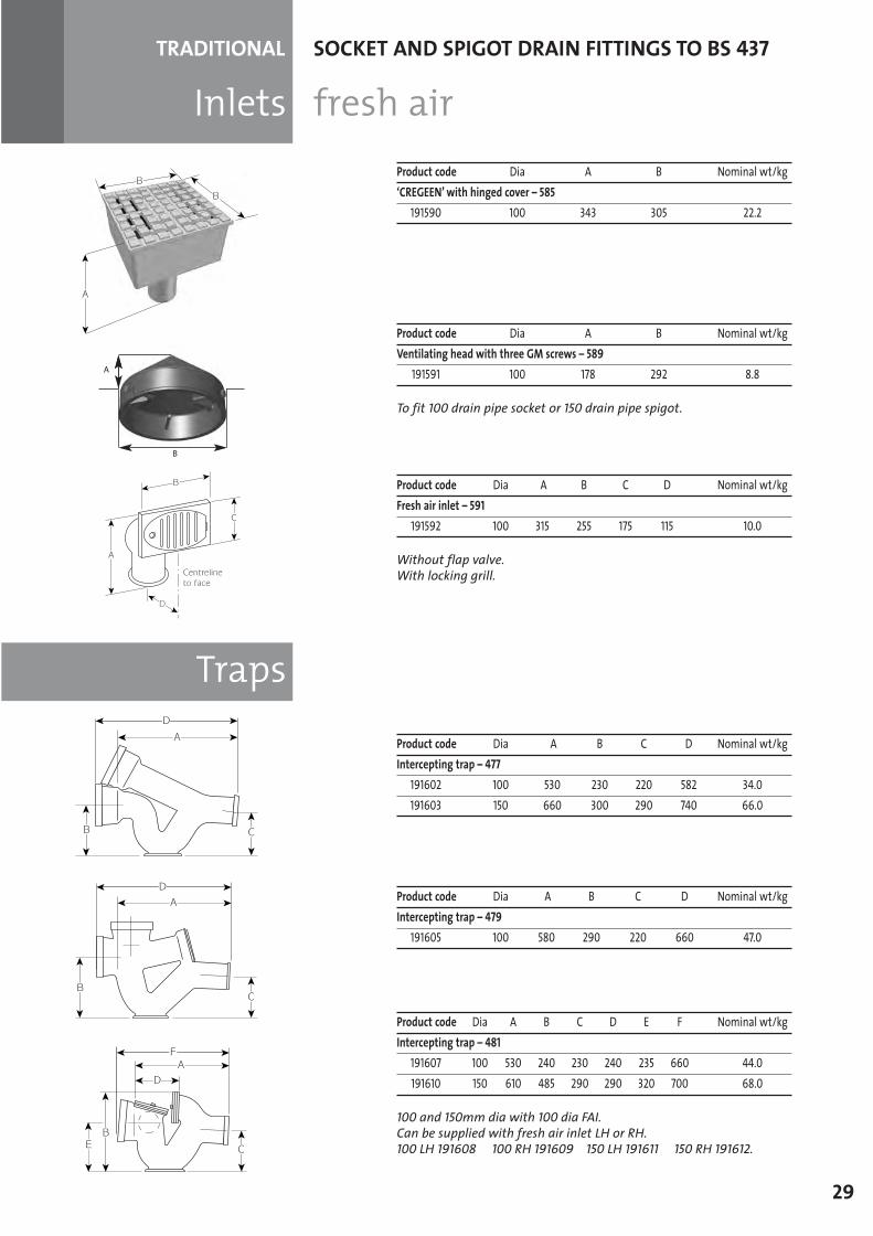
Inlets fresh airSOCKET AND SPIGOT DRAIN FITTINGS TO BS 437
Product code Dia A B Nominal wt/kg‘CREGEEN’ with hinged cover – 585
191590 100 343 305 22.2
Product code Dia A B Nominal wt/kgVentilating head with three GM screws – 589
191591 100 178 292 8.8
To fit 100 drain pipe socket or 150 drain pipe spigot.
Product code Dia A B C D Nominal wt/kgFresh air inlet – 591
191592 100 315 255 175 115 10.0
Without flap valve.With locking grill.
Product code Dia A B C D Nominal wt/kgIntercepting trap – 477
191602 100 530 230 220 582 34.0191603 150 660 300 290 740 66.0
Product code Dia A B C D Nominal wt/kgIntercepting trap – 479
191605 100 580 290 220 660 47.0
Product code Dia A B C D E F Nominal wt/kgIntercepting trap – 481
191607 100 530 240 230 240 235 660 44.0191610 150 610 485 290 290 320 700 68.0
100 and 150mm dia with 100 dia FAI.Can be supplied with fresh air inlet LH or RH.100 LH 191608 100 RH 191609 150 LH 191611 150 RH 191612.
A
B
SGPL_119744_Timesaver Update 2012 Pages 1 to 40_REPRO_SF:Layout 1 30/04/2012 16:34 Page 29
Eureka anti-flooding trunk valves
30
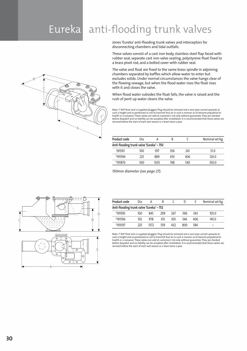
Jones ‘Eureka’ anti-flooding trunk valves and interceptors fordisconnecting chambers and tidal outfalls.
These valves consist of a cast iron body, stainless steel flap faced withrubber seal, separate cast iron valve seating, polystyrene float fixed toa brass pivot rod, and a bolted cover with rubber seal.
The valve and float are fixed to the same brass spindle in adjoiningchambers separated by baffles which allow water to enter butexcludes solids. Under normal circumstances the valve hangs clear ofthe flowing sewage, but when the flood water rises the float riseswith it and closes the valve.
When flood water subsides the float falls, the valve is raised and therush of pent up water cleans the valve.
Note: 1" BSP float vent is supplied plugged. Plug should be removed and a vent pipe carried upwards tosuch a height and so positioned as not to transmit foul air in such a manner as to become prejudicial tohealth or a nuisance. These valves are sold at customers’ risk only without guarantee. They are checkedbefore despatch and no liability can be accepted after installation. It is recommended that these valves areserviced before the start of each wet season or a least twice a year.
Product code Dia A B C Nominal wt/kgAnti-flooding trunk valve ‘Eureka’ – 750
191593 100 597 356 241 51.0†191594 225 889 610 406 120.0†191870 300 1035 748 540 350.0
150mm diameter (see page 27).
Product code Dia A B C D E Nominal wt/kgAnti-flooding trunk valve ‘Eureka’ – 752
†191595 100 845 299 267 396 343 105.0†191596 150 978 355 305 546 406 145.0†191597 225 1372 559 432 800 584 –
Note: 1" BSP float vent is supplied plugged. Plug should be removed and a vent pipe carried upwards tosuch a height and so positioned as not to transmit foul air in such a manner as to become prejudicial tohealth or a nuisance. These valves are sold at customers’ risk only without guarantee. They are checkedbefore despatch and no liability can be accepted after installation. It is recommended that these valves areserviced before the start of each wet season or a least twice a year.
SGPL_119744_Timesaver Update 2012 Pages 1 to 40_REPRO_SF:Layout 1 30/04/2012 16:34 Page 30
Petrol intercepting bends
Ball valve anti-flooding
31
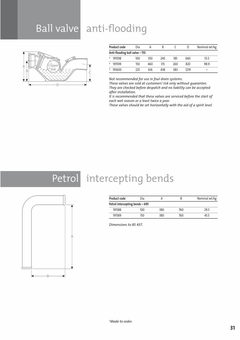
Product code Dia A B C D Nominal wt/kgAnti-flooding ball valve – 755† 191598 100 350 240 185 660 53.5† 191599 150 460 315 260 820 98.9† 191600 225 616 438 383 1219 –
Not recommended for use in foul drain systems.These valves are sold at customers’ risk only without guarantee.They are checked before despatch and no liability can be acceptedafter installation.It is recommended that these valves are serviced before the start ofeach wet season or a least twice a year.These valves should be set horizontally with the aid of a spirit level.
Product code Dia A B Nominal wt/kgPetrol intercepting bends – 695
191588 100 380 760 29.5191589 150 380 760 45.5
Dimensions to BS 437.
†Made to order.
SGPL_119744_Timesaver Update 2012 Pages 1 to 40_REPRO_SF:Layout 1 30/04/2012 16:34 Page 31
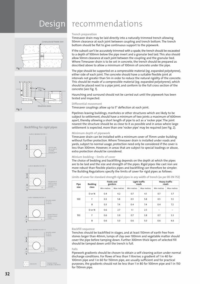
Fig. 1
Design recommendationsTrench preparationTimesaver drain may be laid directly into a naturally trimmed trench allowing50mm clearance at each joint between coupling and trench bottom. The trenchbottom should be flat to give continuous support to the pipework.
If the subsoil can’t be accurately trimmed with a spade, the trench should be excavatedto a depth of 100mm below the pipe invert and a granular bed laid. This also shouldallow 50mm clearance at each joint between the coupling and the granular bed.Where Timesaver drain is to be set in concrete, the trench should be prepared asdescribed above to allow a minimum of 100mm of concrete under the pipe.
The pipe should be supported on a compressible material (eg. expanded polystyrene),either side of each joint. The concrete should have a suitable flexible joint atintervals not greater than 5m in order to reduce the natural rigidity of the concrete.This should be made of a compressible material (eg. expanded polystyrene), whichshould be placed next to a pipe joint, and conform to the full cross section of theconcrete (see Fig. 1).
Haunching and surround should not be carried out until the pipework has beentested and inspected.
Differential movementTimesaver couplings allow up to 5° deflection at each joint.
Pipelines leaving buildings, manholes or other structures which are likely to besubject to settlement, should have a minimum of two joints a maximum of 600mmapart, thereby allowing a short length of pipe to act as a ‘rocker pipe’. The jointnearest the structure should be as close to it as possible and in areas where largesettlement is expected, more than one ‘rocker pipe’ may be required (see Fig. 2).
Minimum depth of pipeworkTimesaver drain can be installed with a minimum cover of 75mm under buildingwithout further protection. Where Timesaver drain is installed under roads andyards, subject to normal usage, protection need only be considered if the cover isless than 300mm. However, in areas that are subject to special loadings or abuse,extra protection should be considered.
Minium bedding – limits of coverThe choice of bedding and backfilling depends on the depth at which the pipes are to be laid and the size and strength of the pipes. Rigid pipes like cast iron aremore robust than flexible plastics pipes and backfilling can therefore be simpler.The Building Regulations specify the limits of cover for rigid pipes as follows:
Limits of cover for standard strength rigid pipes in any width of trench (as per BS EN 752)
Backfill sequenceTrenches should be backfilled in stages, and at least 150mm of earth free fromstones larger than 40mm, lumps of clay over 100mm and vegetable matter shouldcover the pipe before tamping down. Further 300mm thick layers of selected fillshould be tamped down until the trench is full.
FallsPipework gradients should be chosen to obtain a self-cleaning action under normaldischarge conditions. For flows of less than 1 litre/sec a gradient of 1 in 40 for100mm pipe and 1 in 60 for 150mm pipe, are usually sufficient and for practicalpurposes, the gradients should not be less than 1 in 80 for 100mm pipe and 1 in 150for 150mm pipe.
Pipesize
Beddingclass
Fields and gardens
Light traffic roads
Heavy traffic roads
Min metres Max metres Min metres Max metres Min metres Max metres
100
D or N 0.4 4.2 0.7 4.1 0.7 3.7
F 0.3 5.8 0.5 5.8 0.5 5.5
B 0.3 7.4 0.4 7.4 0.4 7.2
150
D or N 0.6 2.7 1.1 2.5 – –
F 0.6 3.9 0.7 3.8 0.7 3.3
B 0.6 5.0 0.6 5.0 0.6 4.6
32
Fig. 2
Backfilling for rigid pipes
SGPL_119744_Timesaver Update 2012 Pages 1 to 40_REPRO_SF:Layout 1 30/04/2012 16:34 Page 32
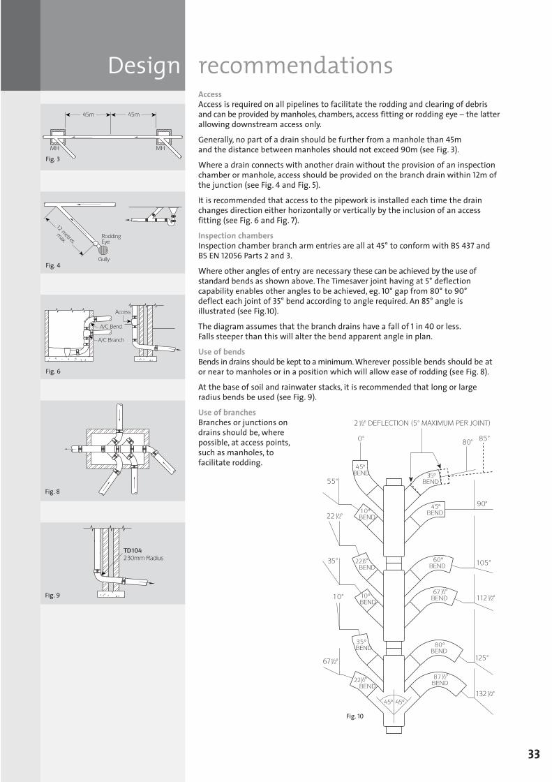
Design recommendationsAccessAccess is required on all pipelines to facilitate the rodding and clearing of debrisand can be provided by manholes, chambers, access fitting or rodding eye – the latterallowing downstream access only.
Generally, no part of a drain should be further from a manhole than 45m and the distance between manholes should not exceed 90m (see Fig. 3).
Where a drain connects with another drain without the provision of an inspectionchamber or manhole, access should be provided on the branch drain within 12m ofthe junction (see Fig. 4 and Fig. 5).
It is recommended that access to the pipework is installed each time the drainchanges direction either horizontally or vertically by the inclusion of an accessfitting (see Fig. 6 and Fig. 7).
Inspection chambersInspection chamber branch arm entries are all at 45° to conform with BS 437 andBS EN 12056 Parts 2 and 3.
Where other angles of entry are necessary these can be achieved by the use ofstandard bends as shown above. The Timesaver joint having at 5° deflectioncapability enables other angles to be achieved, eg. 10° gap from 80° to 90° deflect each joint of 35° bend according to angle required. An 85° angle isillustrated (see Fig.10).
The diagram assumes that the branch drains have a fall of 1 in 40 or less. Falls steeper than this will alter the bend apparent angle in plan.
Use of bendsBends in drains should be kept to a minimum.Wherever possible bends should be ator near to manholes or in a position which will allow ease of rodding (see Fig. 8).
At the base of soil and rainwater stacks, it is recommended that long or largeradius bends be used (see Fig. 9).
Use of branchesBranches or junctions ondrains should be, wherepossible, at access points,such as manholes, tofacilitate rodding.
33
Fig. 3
Fig. 4
Fig. 6
Fig. 8
Fig. 9
Fig. 10
SGPL_119744_Timesaver Update 2012 Pages 1 to 40_REPRO_SF:Layout 1 30/04/2012 16:34 Page 33
Support recommended forsuspended drainage
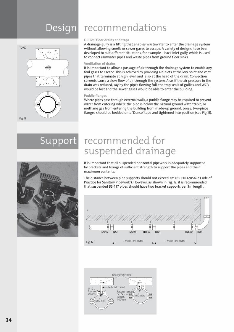
Design recommendationsGullies, floor drains and trapsA drainage gully is a fitting that enables wastewater to enter the drainage systemwithout allowing smells or sewer gases to escape. A variety of designs have beendeveloped to suit different situations, for example – back inlet gully, which is usedto connect rainwater pipes and waste pipes from ground floor sinks.
Ventilation of drainsIt is important to allow a passage of air through the drainage system to enable anyfoul gases to escape. This is achieved by providing air inlets at the low point and ventpipes that terminate at high level, and also at the head of the drain. Convectioncurrents cause a slow flow of air through the system. Also, if the air pressure in thedrain was reduced, say by the pipes flowing full, the trap seals of gullies and WC’swould be lost and the sewer gases would be able to enter the building.
Puddle flangesWhere pipes pass through external walls, a puddle flange may be required to preventwater from entering where the pipe is below the natural ground water table, ormethane gas from entering the building from made-up ground. Loose, two-pieceflanges should be bedded onto ‘Denso’ tape and tightened into position (see Fig.11).
It is important that all suspended horizontal pipework is adequately supported by brackets and fixings of sufficient strength to support the pipes and theirmaximum contents.
The distance between pipe supports should not exceed 3m (BS EN 12056-2 Code ofPractice for Sanitary Pipework’). However, as shown in Fig. 12, it is recommendedthat suspended BS 437 pipes should have two bracket supports per 3m length.
34
Fig. 11
TD777
Fig. 12
SGPL_119744_Timesaver Update 2012 Pages 1 to 40_REPRO_SF:Layout 1 30/04/2012 16:34 Page 34
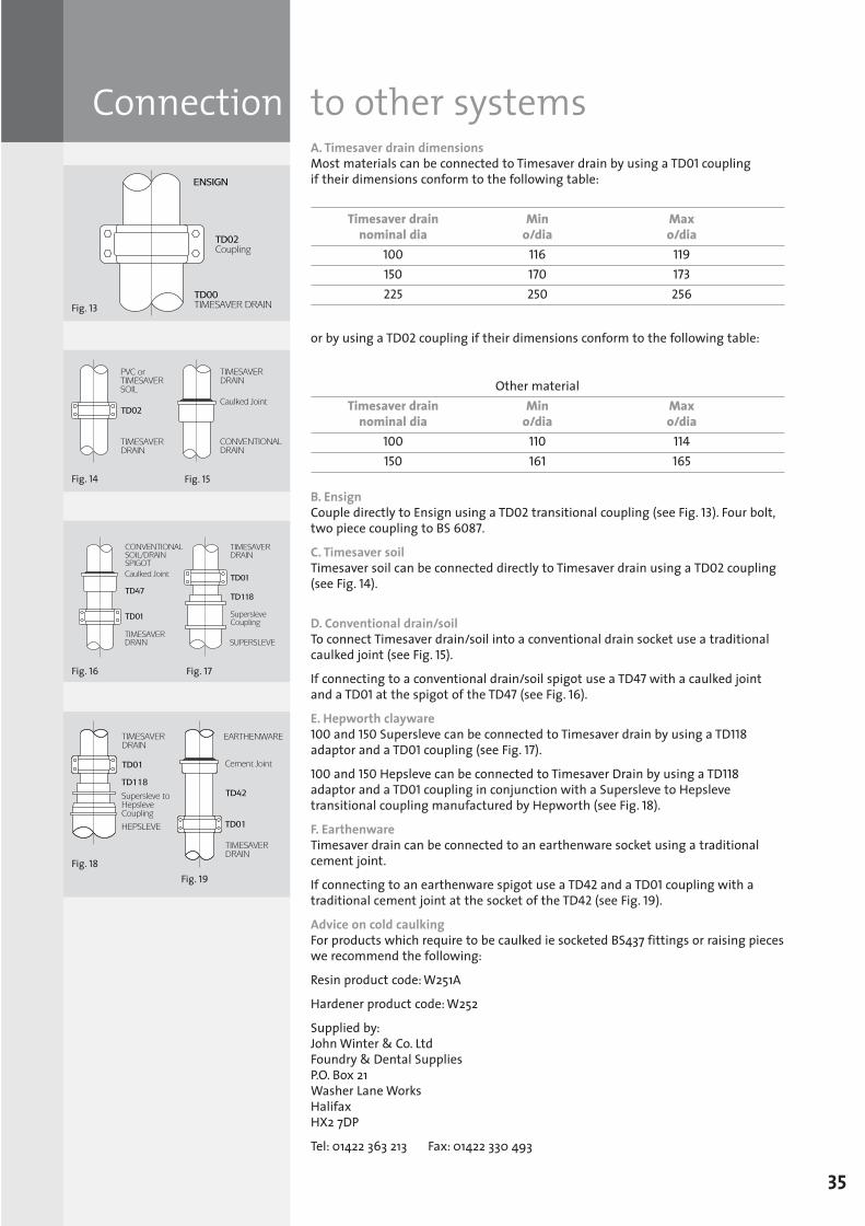
Connection to other systemsA. Timesaver drain dimensionsMost materials can be connected to Timesaver drain by using a TD01 coupling if their dimensions conform to the following table:
Timesaver drain Min Maxnominal dia o/dia o/dia
100 116 119150 170 173225 250 256
or by using a TD02 coupling if their dimensions conform to the following table:
Other materialTimesaver drain Min Max
nominal dia o/dia o/dia100 110 114150 161 165
B. EnsignCouple directly to Ensign using a TD02 transitional coupling (see Fig. 13). Four bolt,two piece coupling to BS 6087.
C. Timesaver soil Timesaver soil can be connected directly to Timesaver drain using a TD02 coupling(see Fig. 14).
D. Conventional drain/soilTo connect Timesaver drain/soil into a conventional drain socket use a traditionalcaulked joint (see Fig. 15).
If connecting to a conventional drain/soil spigot use a TD47 with a caulked joint and a TD01 at the spigot of the TD47 (see Fig. 16).
E. Hepworth clayware100 and 150 Supersleve can be connected to Timesaver drain by using a TD118adaptor and a TD01 coupling (see Fig. 17).
100 and 150 Hepsleve can be connected to Timesaver Drain by using a TD118adaptor and a TD01 coupling in conjunction with a Supersleve to Hepslevetransitional coupling manufactured by Hepworth (see Fig. 18).
F. EarthenwareTimesaver drain can be connected to an earthenware socket using a traditionalcement joint.
If connecting to an earthenware spigot use a TD42 and a TD01 coupling with atraditional cement joint at the socket of the TD42 (see Fig. 19).
Advice on cold caulkingFor products which require to be caulked ie socketed BS437 fittings or raising pieceswe recommend the following:
Resin product code: W251A
Hardener product code: W252
Supplied by: John Winter & Co. LtdFoundry & Dental SuppliesP.O. Box 21Washer Lane WorksHalifaxHX2 7DP
Tel: 01422 363 213 Fax: 01422 330 493
35
Fig. 13
Fig. 14 Fig. 15
Fig. 16 Fig. 17
Fig. 18Fig. 19
SGPL_119744_Timesaver Update 2012 Pages 1 to 40_REPRO_SF:Layout 1 30/04/2012 16:34 Page 35
Quality control procedures and testsAll pipes, fittings and couplings are subjected to tests in accordance with therequirements of the relevant British Standard prior to despatch from works.
Pipes and fittingsA. Hydrostatic testPipes and fittings, after coating, conform to the hydrostatic pressure requirements of BS 437:
Pipes 345kPa (3.45 Bars)Fittings 170kPa (1.70 Bars)
The test pressure is applied internally and maintained for not less than 15 secondsand up to a maximum of one minute.
B. Crushing testPipes and, where applicable, fittings conform to the BS 437 requirements of beingcapable of withstanding a test load of 150kN per metre run.
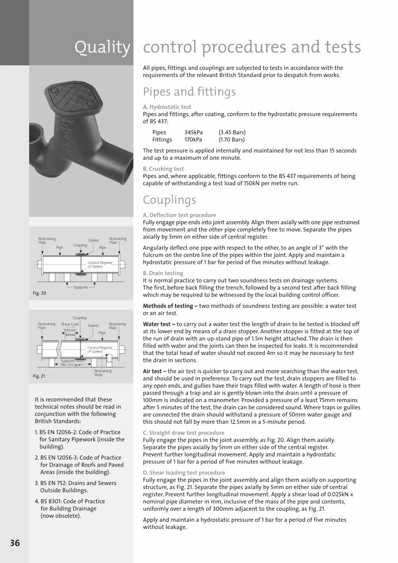
CouplingsA. Deflection test procedureFully engage pipe ends into joint assembly. Align them axially with one pipe restrainedfrom movement and the other pipe completely free to move. Separate the pipesaxially by 5mm on either side of central register.
Angularly deflect one pipe with respect to the other, to an angle of 3° with thefulcrum on the centre line of the pipes within the joint. Apply and maintain ahydrostatic pressure of 1 bar for period of five minutes without leakage.
B. Drain testingIt is normal practice to carry out two soundness tests on drainage systems. The first, before back filling the trench, followed by a second test after back fillingwhich may be required to be witnessed by the local building control officer.
Methods of testing – two methods of soundness testing are possible: a water testor an air test.
Water test – to carry out a water test the length of drain to be tested is blocked offat its lower end by means of a drain stopper. Another stopper is fitted at the top ofthe run of drain with an up-stand pipe of 1.5m height attached. The drain is thenfilled with water and the joints can then be inspected for leaks. It is recommendedthat the total head of water should not exceed 4m so it may be necessary to testthe drain in sections.
Air test – the air test is quicker to carry out and more searching than the water test,and should be used in preference. To carry out the test, drain stoppers are filled toany open ends, and gullies have their traps filled with water. A length of hose is thenpassed through a trap and air is gently blown into the drain until a pressure of100mm is indicated on a manometer. Provided a pressure of a least 75mm remainsafter 5minutes of the test, the drain can be considered sound. Where traps or gulliesare connected the drain should withstand a pressure of 50mm water gauge andthis should not fall by more than 12.5mm in a 5-minute period.
C. Straight draw test procedureFully engage the pipes in the joint assembly, as Fig. 20. Align them axially. Separate the pipes axially by 5mm on either side of the central register. Prevent further longitudinal movement. Apply and maintain a hydrostatic pressure of 1 bar for a period of five minutes without leakage.
D. Shear loading test procedureFully engage the pipes in the joint assembly and align them axially on supportingstructure, as Fig. 21. Separate the pipes axially by 5mm on either side of centralregister. Prevent further longitudinal movement. Apply a shear load of 0.025kN xnominal pipe diameter in mm, inclusive of the mass of the pipe and contents,uniformly over a length of 300mm adjacent to the coupling, as Fig. 21.
Apply and maintain a hydrostatic pressure of 1 bar for a period of five minuteswithout leakage.
Fig. 20
Fig. 21
36
It is recommended that thesetechnical notes should be read inconjunction with the followingBritish Standards:
1. BS EN 12056-2: Code of Practicefor Sanitary Pipework (inside thebuilding).
2. BS EN 12056-3: Code of Practicefor Drainage of Roofs and PavedAreas (inside the building).
3. BS EN 752: Drains and SewersOutside Buildings.
4. BS 8301: Code of Practice for Building Drainage (now obsolete).
SGPL_119744_Timesaver Update 2012 Pages 1 to 40_REPRO_SF:Layout 1 30/04/2012 16:34 Page 36
Floor drains adjustable
37
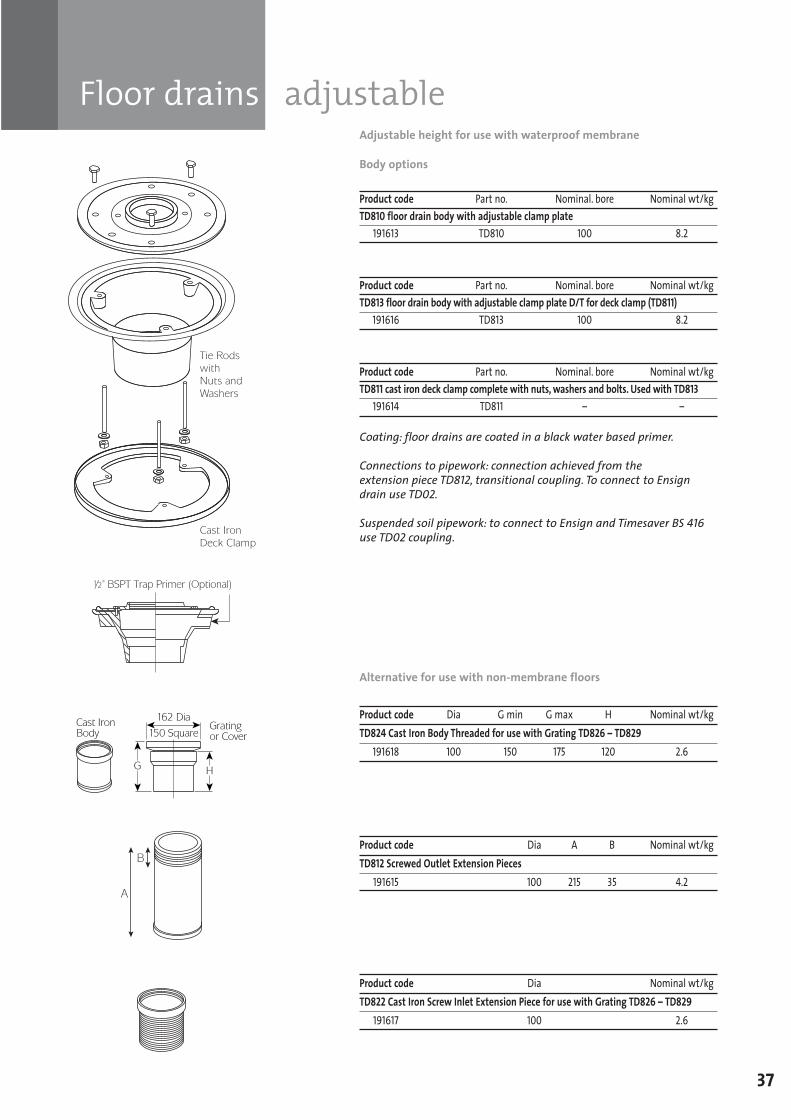
Adjustable height for use with waterproof membrane
Body options
Product code Part no. Nominal. bore Nominal wt/kgTD810 floor drain body with adjustable clamp plate
191613 TD810 100 8.2
Product code Part no. Nominal. bore Nominal wt/kgTD813 floor drain body with adjustable clamp plate D/T for deck clamp (TD811)
191616 TD813 100 8.2
Product code Part no. Nominal. bore Nominal wt/kgTD811 cast iron deck clamp complete with nuts, washers and bolts. Used with TD813
191614 TD811 – –
Coating: floor drains are coated in a black water based primer.
Connections to pipework: connection achieved from the extension piece TD812, transitional coupling. To connect to Ensigndrain use TD02.
Suspended soil pipework: to connect to Ensign and Timesaver BS 416use TD02 coupling.
Alternative for use with non-membrane floors
Product code Dia G min G max H Nominal wt/kgTD824 Cast Iron Body Threaded for use with Grating TD826 – TD829
191618 100 150 175 120 2.6
Product code Dia A B Nominal wt/kgTD812 Screwed Outlet Extension Pieces
191615 100 215 35 4.2
Product code Dia Nominal wt/kgTD822 Cast Iron Screw Inlet Extension Piece for use with Grating TD826 – TD829
191617 100 2.6
SGPL_119744_Timesaver Update 2012 Pages 1 to 40_REPRO_SF:Layout 1 30/04/2012 16:34 Page 37
Floor drains adjustable
38
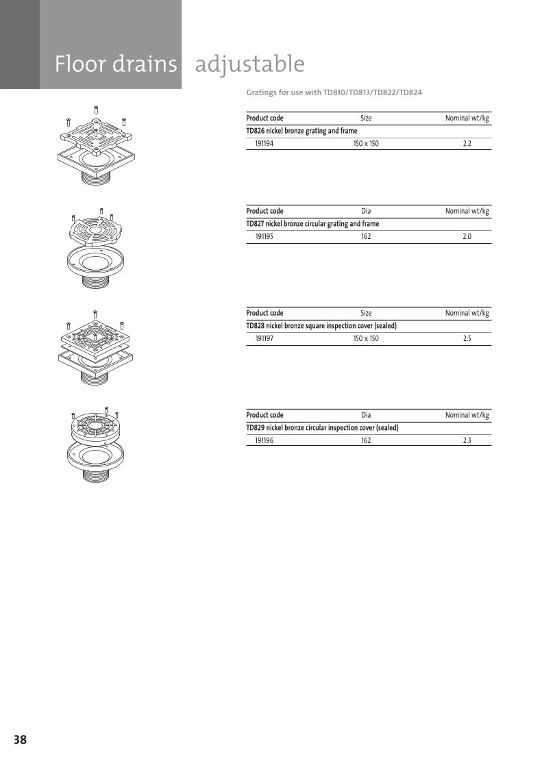
Gratings for use with TD810/TD813/TD822/TD824
Product code Size Nominal wt/kgTD826 nickel bronze grating and frame
191194 150 x 150 2.2
Product code Dia Nominal wt/kgTD827 nickel bronze circular grating and frame
191195 162 2.0
Product code Size Nominal wt/kgTD828 nickel bronze square inspection cover (sealed)
191197 150 x 150 2.5
Product code Dia Nominal wt/kgTD829 nickel bronze circular inspection cover (sealed)
191196 162 2.3
SGPL_119744_Timesaver Update 2012 Pages 1 to 40_REPRO_SF:Layout 1 30/04/2012 16:34 Page 38
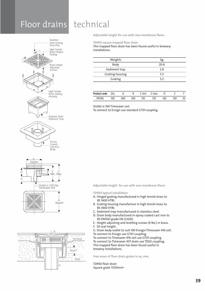
Floor drains technical
39
Adjustable height for use with non-membrane floors
TD950 square trapped floor drainThis trapped floor drain has been found useful in breweryinstallations.
Weights kgBody 20.6
Sediment trap 2.8Grating housing 5.3
Grating 5.2
Product code Dia A B C min C max D E F191396 100 400 300 310 335 160 100 50
Outlet is 100 Timesaver soil.To connect to Ensign use standard GT01 coupling.
Adjustable height for use with non-membrane floors
TD950 typical installationA. Hinged grating manufactured in high tensile brass to
BS 1400 HTBI.B. Grating housing manufacture in high tensile brass to
BS 1400 HTBI.C. Sediment trap manufactured in stainless steel.D. Drain body manufactured in epoxy coated cast iron to
BS EN1561 grade EN-JL1020.E. Height adjusting and levelling screws (4 No.) in brass.F. 50 seal height.G. Drain body outlet to suit 100 Ensign/Timesaver 416 soil.To connect to Ensign use GT01 coupling.To connect to Timesaver 416 soil use GT01 coupling.To connect to Timesaver 437 drain use TD02 coupling.This trapped floor drain has been found useful in brewery installations.
Free areas of floor drain grates in sq. mm.
TD950 floor drain Square grate 11250mm2
SGPL_119744_Timesaver Update 2012 Pages 1 to 40_REPRO_SF:Layout 1 30/04/2012 16:34 Page 39
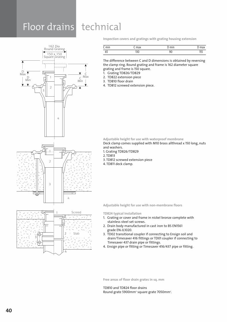
Floor drains technical
40
Inspection covers and gratings with grating housing extension
C min C max D min D max65 130 90 155
The difference between C and D dimensions is obtained by reversingthe clamp ring. Round grating and frame is 162 diameter squaregrating and frame is 150 square.1. Grating TD826/TD8292. TD822 extension piece3. TD810 floor drain4. TD812 screwed extension piece.
Adjustable height for use with waterproof membrane Deck clamp comes supplied with M10 brass allthread x 150 long, nutsand washers.1. Grating TD826/TD8292. TD8133. TD812 screwed extension piece4. TD811 deck clamp.
Adjustable height for use with non-membrane floors
TD824 typical Installation1. Grating or cover and frame in nickel bronze complete with
stainless steel set screws.2. Drain body manufactured in cast iron to BS EN1561
grade EN-JL1020.3. TD02 transitional coupler if connecting to Ensign soil and
drain/Timesaver 416 fittings or TD01 coupler if connecting toTimesaver 437 drain pipe or fittings.
4. Ensign pipe or fitting or Timesaver 416/437 pipe or fitting.
Free areas of floor drain grates in sq. mm
TD810 and TD824 floor drainsRound grate 5900mm2 square grate 7050mm2.
SGPL_119744_Timesaver Update 2012 Pages 1 to 40_REPRO_SF:Layout 1 30/04/2012 16:34 Page 40
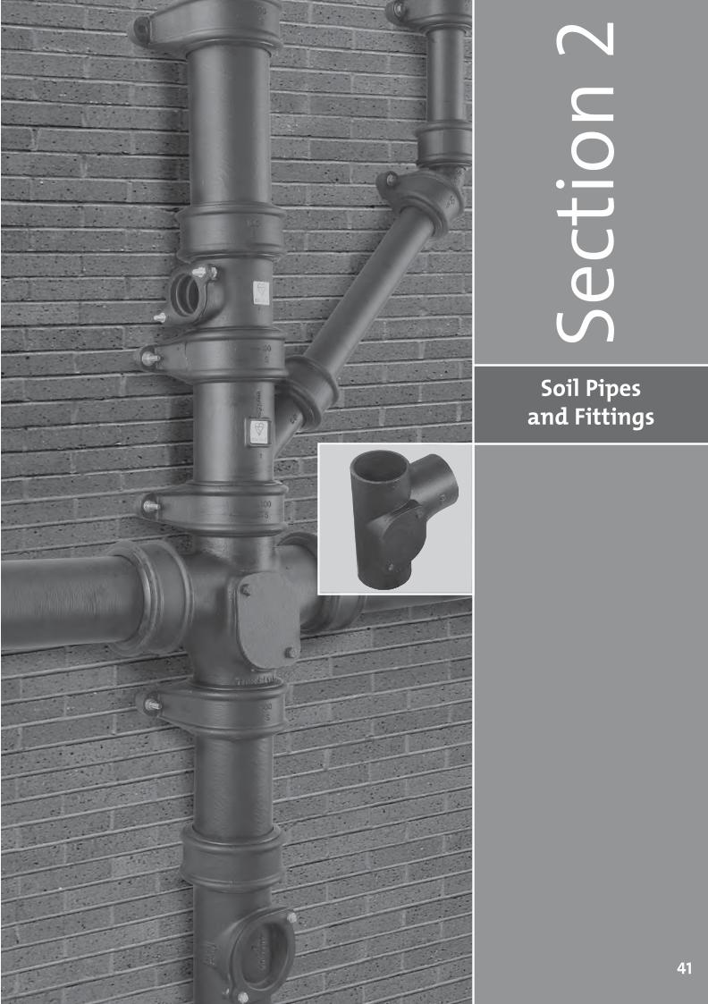
Soil Pipes and Fittings
Sect
ion 2
41
SGPL_119744_Timesaver Update 2012 Pages 41 to 68_REPRO_SF:Layout 1 30/04/2012 16:36 Page 41
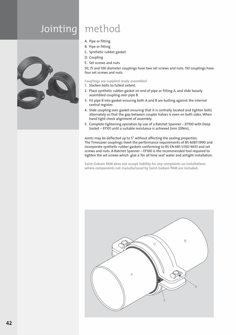
Jointing methodA. Pipe or fittingB. Pipe or fittingC. Synthetic rubber gasketD. CouplingE. Set screws and nuts50, 75 and 100 diameter couplings have two set screws and nuts. 150 couplings havefour set screws and nuts.
Couplings are supplied ready assembled1. Slacken bolts to fullest extent.2. Place synthetic rubber gasket on end of pipe or fitting A, and slide looselyassembled coupling over pipe B.
3. Fit pipe B into gasket ensuring both A and B are butting against the internalcentral register.
4. Slide coupling over gasket ensuring that it is centrally located and tighten boltsalternately so that the gap between coupler halves is even on both sides. Whenhand tight check alignment of assembly.
5. Complete tightening operation by use of a Ratchet Spanner – EF100 with DeepSocket – EF101 until a suitable resistance is achieved (min 20Nm).
Joints may be deflected up to 5° without affecting the sealing properties. The Timesaver couplings meet the performance requirements of BS 6087:1990 andincorporate synthetic rubber gaskets conforming to BS EN 681-1/ISO 4633 and setscrews and nuts. A Ratchet Spanner – EF100 is the recommended tool required totighten the set screws which give a ‘for all time seal’ water and airtight installation.
Saint-Gobain PAM does not accept liability for any complaints on installationswhere components not manufactured by Saint-Gobain PAM are included.
42
SGPL_119744_Timesaver Update 2012 Pages 41 to 68_REPRO_SF:Layout 1 30/04/2012 16:36 Page 42
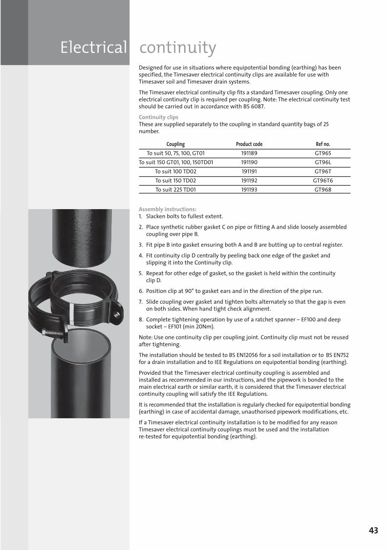
Electrical continuityDesigned for use in situations where equipotential bonding (earthing) has beenspecified, the Timesaver electrical continuity clips are available for use withTimesaver soil and Timesaver drain systems.
The Timesaver electrical continuity clip fits a standard Timesaver coupling. Only oneelectrical continuity clip is required per coupling. Note: The electrical continuity testshould be carried out in accordance with BS 6087.
Continuity clipsThese are supplied separately to the coupling in standard quantity bags of 25number.
Coupling Product code Ref no.To suit 50, 75, 100, GT01 191189 GT965
To suit 150 GT01, 100, 150TD01 191190 GT96LTo suit 100 TD02 191191 GT96TTo suit 150 TD02 191192 GT96T6To suit 225 TD01 191193 GT968
Assembly instructions:1. Slacken bolts to fullest extent.
2. Place synthetic rubber gasket C on pipe or fitting A and slide loosely assembledcoupling over pipe B.
3. Fit pipe B into gasket ensuring both A and B are butting up to central register.
4. Fit continuity clip D centrally by peeling back one edge of the gasket andslipping it into the Continuity clip.
5. Repeat for other edge of gasket, so the gasket is held within the continuity clip D.
6. Position clip at 90° to gasket ears and in the direction of the pipe run.
7. Slide coupling over gasket and tighten bolts alternately so that the gap is evenon both sides. When hand tight check alignment.
8. Complete tightening operation by use of a ratchet spanner – EF100 and deepsocket – EF101 (min 20Nm).
Note: Use one continuity clip per coupling joint. Continuity clip must not be reusedafter tightening.
The installation should be tested to BS EN12056 for a soil installation or to BS EN752for a drain installation and to IEE Regulations on equipotential bonding (earthing).
Provided that the Timesaver electrical continuity coupling is assembled andinstalled as recommended in our instructions, and the pipework is bonded to themain electrical earth or similar earth, it is considered that the Timesaver electricalcontinuity coupling will satisfy the IEE Regulations.
It is recommended that the installation is regularly checked for equipotential bonding(earthing) in case of accidental damage, unauthorised pipework modifications, etc.
If a Timesaver electrical continuity installation is to be modified for any reasonTimesaver electrical continuity couplings must be used and the installation re-tested for equipotential bonding (earthing).
43
SGPL_119744_Timesaver Update 2012 Pages 41 to 68_REPRO_SF:Layout 1 30/04/2012 16:36 Page 43
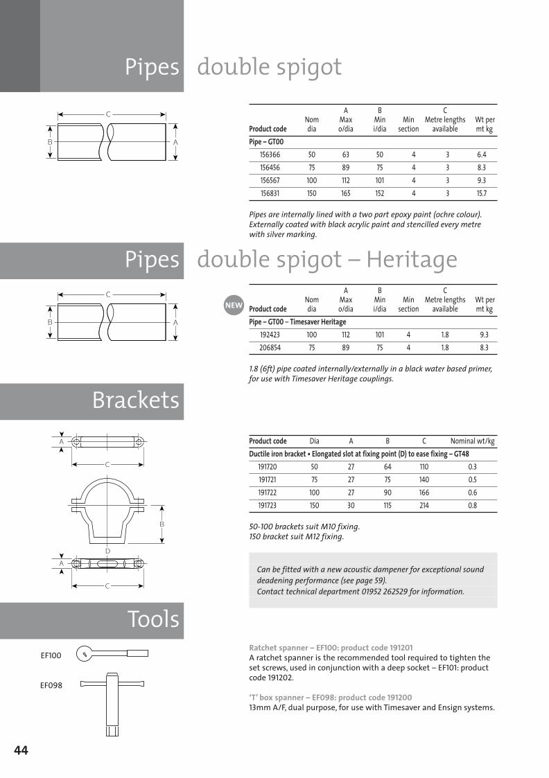
Pipes double spigot
Brackets
Pipes double spigot – Heritage
Tools
44
A B C Nom Max Min Min Metre lengths Wt per
Product code dia o/dia i/dia section available mt kgPipe – GT00
156366 50 63 50 4 3 6.4156456 75 89 75 4 3 8.3156567 100 112 101 4 3 9.3156831 150 165 152 4 3 15.7
Pipes are internally lined with a two part epoxy paint (ochre colour).Externally coated with black acrylic paint and stencilled every metrewith silver marking.
A B C Nom Max Min Min Metre lengths Wt per
Product code dia o/dia i/dia section available mt kgPipe – GT00 – Timesaver Heritage
192423 100 112 101 4 1.8 9.3206854 75 89 75 4 1.8 8.3
1.8 (6ft) pipe coated internally/externally in a black water based primer,for use with Timesaver Heritage couplings.
Product code Dia A B C Nominal wt/kgDuctile iron bracket • Elongated slot at fixing point (D) to ease fixing – GT48
191720 50 27 64 110 0.3191721 75 27 75 140 0.5191722 100 27 90 166 0.6191723 150 30 115 214 0.8
50-100 brackets suit M10 fixing.150 bracket suit M12 fixing.
Can be fitted with a new acoustic dampener for exceptional sounddeadening performance (see page 59). Contact technical department 01952 262529 for information.
Ratchet spanner – EF100: product code 191201A ratchet spanner is the recommended tool required to tighten theset screws, used in conjunction with a deep socket – EF101: productcode 191202.
‘T’ box spanner – EF098: product code 19120013mm A/F, dual purpose, for use with Timesaver and Ensign systems.
EF100
EF098
NEW
SGPL_119744_Timesaver Update 2012 Pages 41 to 68_REPRO_SF:Layout 1 30/04/2012 16:36 Page 44
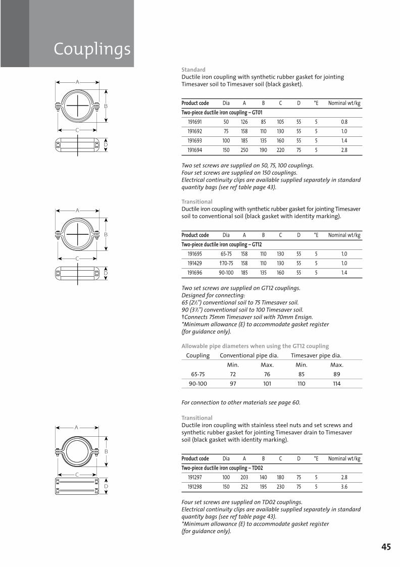
Couplings
45
StandardDuctile iron coupling with synthetic rubber gasket for jointingTimesaver soil to Timesaver soil (black gasket).
Product code Dia A B C D *E Nominal wt/kgTwo-piece ductile iron coupling – GT01
191691 50 126 85 105 55 5 0.8191692 75 158 110 130 55 5 1.0191693 100 185 135 160 55 5 1.4191694 150 250 190 220 75 5 2.8
Two set screws are supplied on 50, 75, 100 couplings.Four set screws are supplied on 150 couplings.Electrical continuity clips are available supplied separately in standardquantity bags (see ref table page 43).
TransitionalDuctile iron coupling with synthetic rubber gasket for jointing Timesaversoil to conventional soil (black gasket with identity marking).
Product code Dia A B C D *E Nominal wt/kgTwo-piece ductile iron coupling – GT12
191695 65-75 158 110 130 55 5 1.0191429 †70-75 158 110 130 55 5 1.0191696 90-100 185 135 160 55 5 1.4
Two set screws are supplied on GT12 couplings.Designed for connecting: 65 (21/2") conventional soil to 75 Timesaver soil.90 (3 1/2") conventional soil to 100 Timesaver soil.†Connects 75mm Timesaver soil with 70mm Ensign.*Minimum allowance (E) to accommodate gasket register (for guidance only).
Allowable pipe diameters when using the GT12 coupling Coupling Conventional pipe dia. Timesaver pipe dia.
Min. Max. Min. Max.65-75 72 76 85 89
90-100 97 101 110 114
For connection to other materials see page 60.
TransitionalDuctile iron coupling with stainless steel nuts and set screws andsynthetic rubber gasket for jointing Timesaver drain to Timesaversoil (black gasket with identity marking).
Product code Dia A B C D *E Nominal wt/kgTwo-piece ductile iron coupling – TD02
191297 100 203 140 180 75 5 2.8191298 150 252 195 230 75 5 3.6
Four set screws are supplied on TD02 couplings.Electrical continuity clips are available supplied separately in standardquantity bags (see ref table page 43).*Minimum allowance (E) to accommodate gasket register (for guidance only).
SGPL_119744_Timesaver Update 2012 Pages 41 to 68_REPRO_SF:Layout 1 30/04/2012 16:36 Page 45
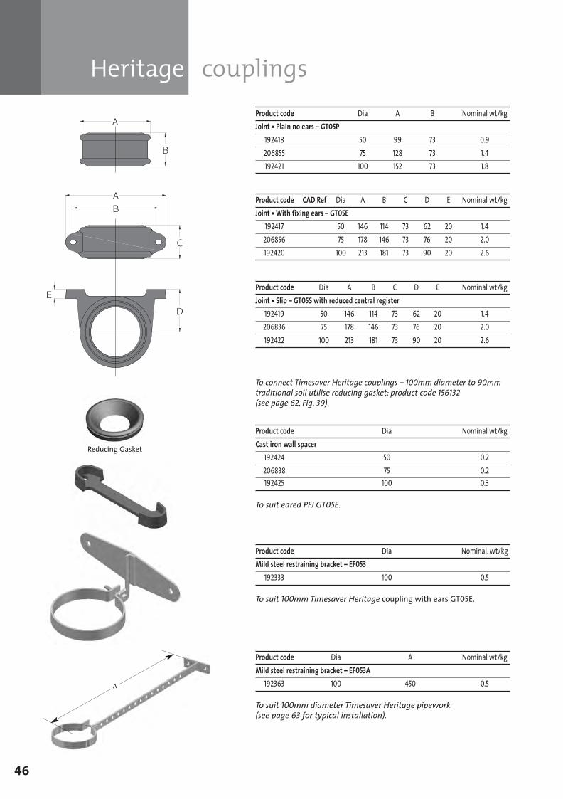
Heritage couplings
46
Product code Dia A B Nominal wt/kgJoint • Plain no ears – GT05P
192418 50 99 73 0.9206855 75 128 73 1.4192421 100 152 73 1.8
Product code Dia A B C D E Nominal wt/kgJoint • Slip – GT05S with reduced central register
192419 50 146 114 73 62 20 1.4206836 75 178 146 73 76 20 2.0192422 100 213 181 73 90 20 2.6
To connect Timesaver Heritage couplings – 100mm diameter to 90mmtraditional soil utilise reducing gasket: product code 156132(see page 62, F ig. 39).
Product code Dia Nominal wt/kgCast iron wall spacer
192424 50 0.2206838 75 0.2192425 100 0.3
To suit eared PFJ GT05E.
Product code Dia Nominal. wt/kgMild steel restraining bracket – EF053
192333 100 0.5
To suit 100mm Timesaver Heritage coupling with ears GT05E.
Product code Dia A Nominal wt/kgMild steel restraining bracket – EF053A
192363 100 450 0.5
To suit 100mm diameter Timesaver Heritage pipework(see page 63 for typical installation).
Product code CAD Ref Dia A B C D E Nominal wt/kgJoint • With fixing ears – GT05E
192417 50 146 114 73 62 20 1.4206856 75 178 146 73 76 20 2.0192420 100 213 181 73 90 20 2.6
Reducing Gasket
A
SGPL_119744_Timesaver Update 2012 Pages 41 to 68_REPRO_SF:Layout 1 30/04/2012 16:36 Page 46
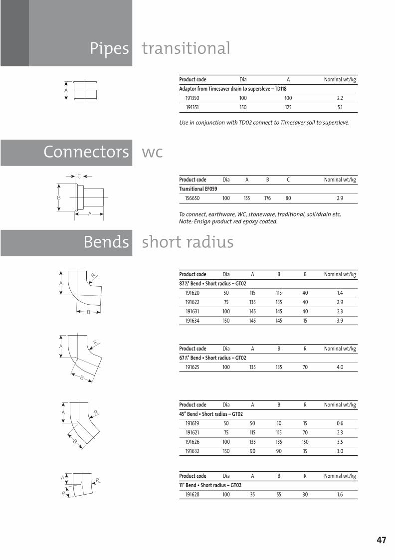
Connectors wc
Pipes transitional
47
Product code Dia A Nominal wt/kgAdaptor from Timesaver drain to supersleve – TD118
191350 100 100 2.2191351 150 125 5.1
Use in conjunction with TD02 connect to Timesaver soil to supersleve.
Product code Dia A B C Nominal wt/kgTransitional EF059
156650 100 155 176 80 2.9
Bends short radius
Product code Dia A B R Nominal wt/kg45° Bend • Short radius – GT02
191619 50 50 50 15 0.6191621 75 115 115 70 2.3191626 100 135 135 150 3.5191632 150 90 90 15 3.0
Product code Dia A B R Nominal wt/kg87 1/2° Bend • Short radius – GT02
191620 50 115 115 40 1.4191622 75 135 135 40 2.9191631 100 145 145 40 2.3191634 150 145 145 15 3.9
Product code Dia A B R Nominal wt/kg67 1/2° Bend • Short radius – GT02
191625 100 135 135 70 4.0
Product code Dia A B R Nominal wt/kg11° Bend • Short radius – GT02
191628 100 35 55 30 1.6
To connect, earthware, WC, stoneware, traditional, soil/drain etc.Note: Ensign product red epoxy coated.
SGPL_119744_Timesaver Update 2012 Pages 41 to 68_REPRO_SF:Layout 1 30/04/2012 16:36 Page 47
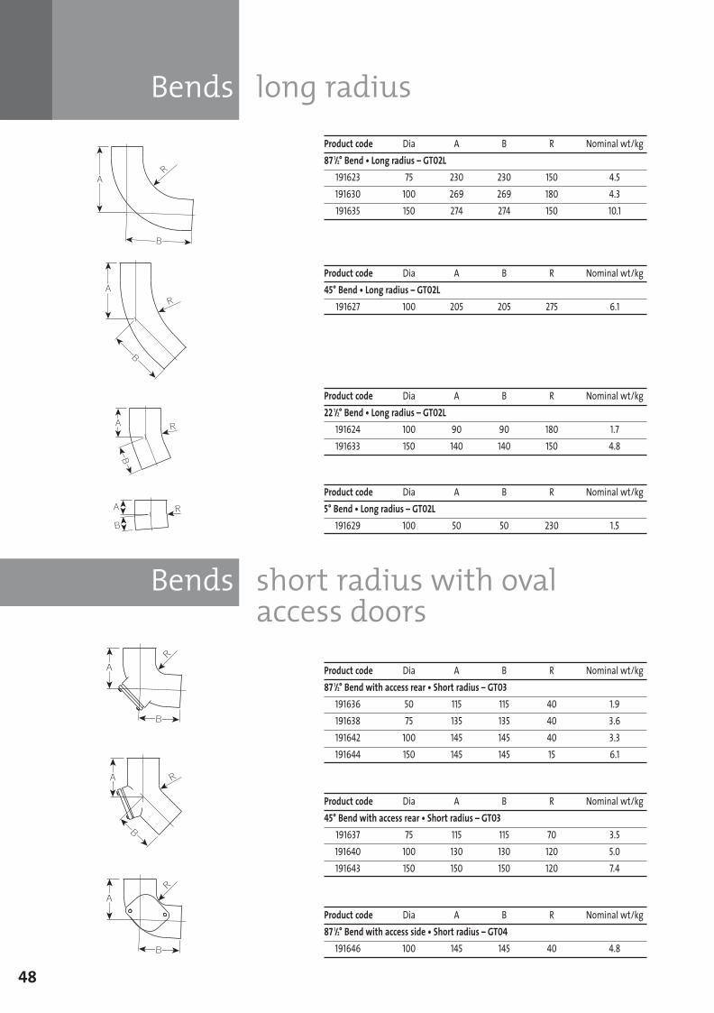
Bends long radius
Bends short radius with ovalaccess doors
48
Product code Dia A B R Nominal wt/kg22 1/2° Bend • Long radius – GT02L
191624 100 90 90 180 1.7191633 150 140 140 150 4.8
Product code Dia A B R Nominal wt/kg87 1/2° Bend • Long radius – GT02L
191623 75 230 230 150 4.5191630 100 269 269 180 4.3191635 150 274 274 150 10.1
Product code Dia A B R Nominal wt/kg45° Bend • Long radius – GT02L
191627 100 205 205 275 6.1
Product code Dia A B R Nominal wt/kg5° Bend • Long radius – GT02L
191629 100 50 50 230 1.5
Product code Dia A B R Nominal wt/kg45° Bend with access rear • Short radius – GT03
191637 75 115 115 70 3.5191640 100 130 130 120 5.0191643 150 150 150 120 7.4
Product code Dia A B R Nominal wt/kg87 1/2° Bend with access rear • Short radius – GT03
191636 50 115 115 40 1.9191638 75 135 135 40 3.6191642 100 145 145 40 3.3191644 150 145 145 15 6.1
Product code Dia A B R Nominal wt/kg87 1/2° Bend with access side • Short radius – GT04
191646 100 145 145 40 4.8
SGPL_119744_Timesaver Update 2012 Pages 41 to 68_REPRO_SF:Layout 1 30/04/2012 16:36 Page 48
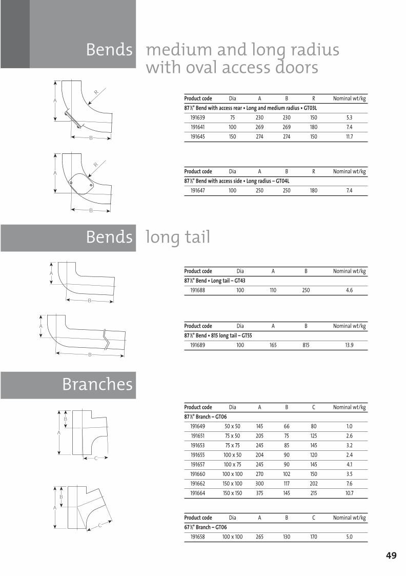
Bends long tail
Branches
Bends medium and long radiuswith oval access doors
49
Product code Dia A B R Nominal wt/kg87 1/2° Bend with access rear • Long and medium radius • GT03L
191639 75 230 230 150 5.3191641 100 269 269 180 7.4191645 150 274 274 150 11.7
Product code Dia A B R Nominal wt/kg87 1/2° Bend with access side • Long radius – GT04L
191647 100 250 250 180 7.4
Product code Dia A B Nominal wt/kg87 1/2° Bend • Long tail – GT43
191688 100 110 250 4.6
Product code Dia A B Nominal wt/kg87 1/2° Bend • 815 long tail – GT55
191689 100 165 815 13.9
Product code Dia A B C Nominal wt/kg67 1/2° Branch – GT06
191658 100 x 100 265 130 170 5.0
Product code Dia A B C Nominal wt/kg87 1/2° Branch – GT06
191649 50 x 50 145 66 80 1.0191651 75 x 50 205 75 125 2.6191653 75 x 75 245 85 145 3.2191655 100 x 50 204 90 120 2.4191657 100 x 75 245 90 145 4.1191660 100 x 100 270 102 150 3.5191662 150 x 100 300 117 202 7.6191664 150 x 150 375 145 215 10.7
SGPL_119744_Timesaver Update 2012 Pages 41 to 68_REPRO_SF:Layout 1 30/04/2012 16:36 Page 49
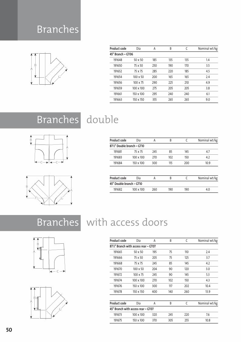
Branches
Branches double
Branches with access doors
50
Product code Dia A B C Nominal wt/kg45° Branch – GT06
191648 50 x 50 185 135 135 1.4191650 75 x 50 250 190 170 3.5191652 75 x 75 285 220 185 4.5191654 100 x 50 200 165 165 2.4191656 100 x 75 290 225 210 4.9191659 100 x 100 275 205 205 3.8191661 150 x 100 295 240 240 6.1191663 150 x 150 355 265 265 9.0
Product code Dia A B C Nominal wt/kg87 1/2° Double branch – GT10
191681 75 x 75 245 85 145 4.7191683 100 x 100 270 102 150 4.2191684 150 x 100 300 115 200 10.9
Product code Dia A B C Nominal wt/kg45° Double branch – GT10
191682 100 x 100 260 190 190 4.0
Product code Dia A B C Nominal wt/kg45° Branch with access rear – GT07
191673 100 x 100 320 245 220 7.6191675 150 x 100 370 305 255 10.8
Product code Dia A B C Nominal wt/kg87 1/2° Branch with access rear – GT07
191665 50 x 50 195 75 110 2.4191666 75 x 50 205 75 125 3.7191668 75 x 75 245 85 145 4.2191670 100 x 50 204 90 120 3.0191672 100 x 75 245 90 145 5.3191674 100 x 100 270 102 150 4.3191676 150 x 100 300 117 202 10.4191678 150 x 150 400 140 260 13.9
SGPL_119744_Timesaver Update 2012 Pages 41 to 68_REPRO_SF:Layout 1 30/04/2012 16:36 Page 50
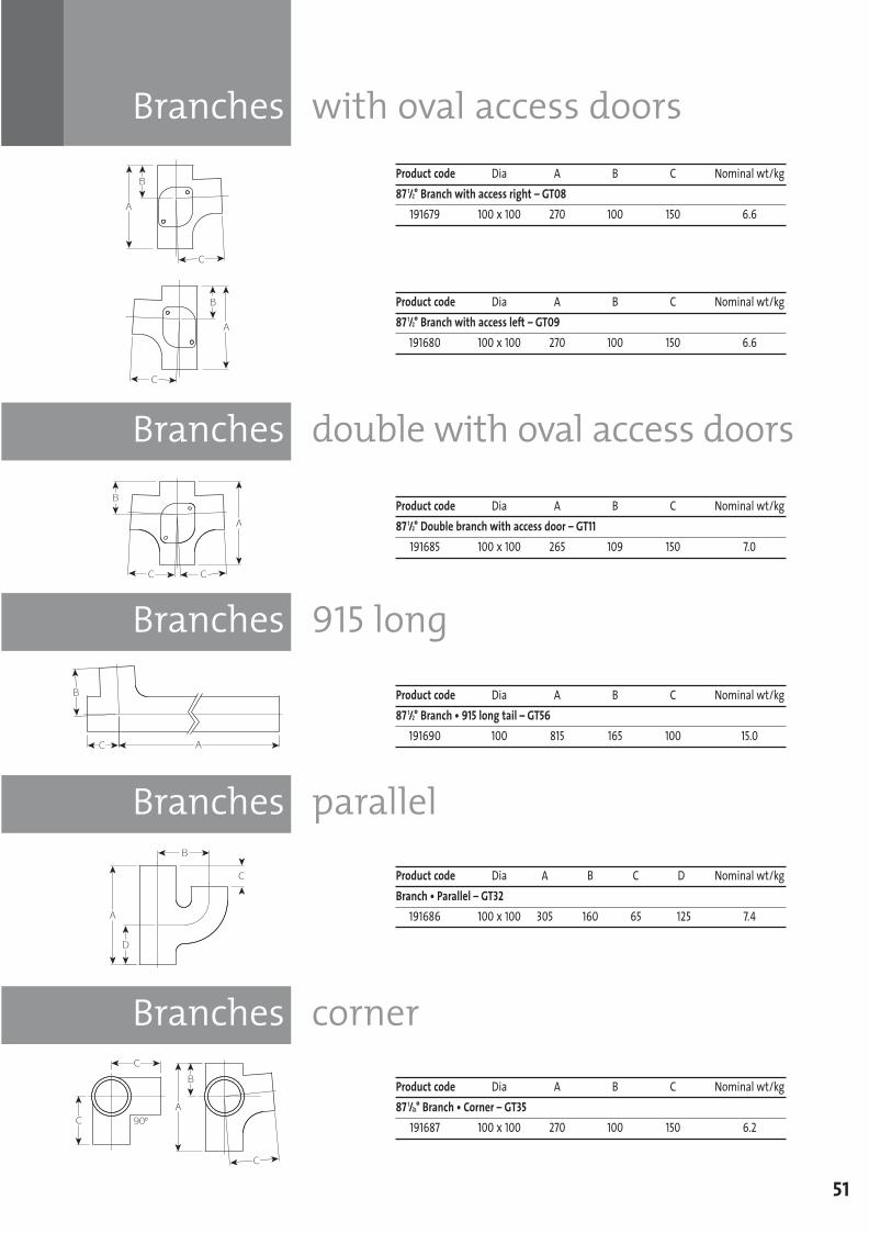
Branches double with oval access doors
Branches 915 long
Branches with oval access doors
51
Product code Dia A B C Nominal wt/kg87 1/2° Branch with access right – GT08
191679 100 x 100 270 100 150 6.6
Product code Dia A B C Nominal wt/kg87 1/2° Branch with access left – GT09
191680 100 x 100 270 100 150 6.6
Product code Dia A B C Nominal wt/kg87 1/2° Double branch with access door – GT11
191685 100 x 100 265 109 150 7.0
Product code Dia A B C Nominal wt/kg87 1/2° Branch • 915 long tail – GT56
191690 100 815 165 100 15.0
Branches parallel
Branches corner
Product code Dia A B C D Nominal wt/kgBranch • Parallel – GT32
191686 100 x 100 305 160 65 125 7.4
Product code Dia A B C Nominal wt/kg87 1/22° Branch • Corner – GT35
191687 100 x 100 270 100 150 6.2
SGPL_119744_Timesaver Update 2012 Pages 41 to 68_REPRO_SF:Layout 1 30/04/2012 16:36 Page 51
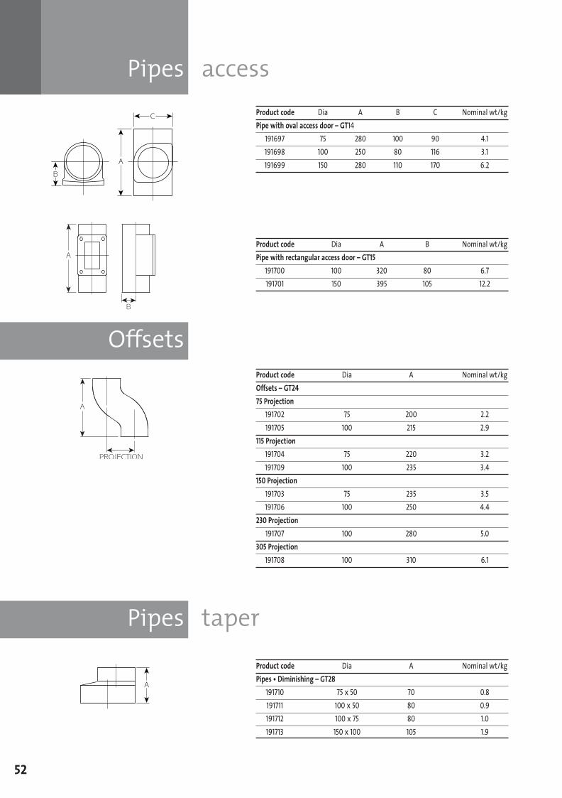
Pipes access
Offsets
Pipes taper
52
Product code Dia A B Nominal wt/kgPipe with rectangular access door – GT15
191700 100 320 80 6.7191701 150 395 105 12.2
Product code Dia A B C Nominal wt/kgPipe with oval access door – GT14
191697 75 280 100 90 4.1191698 100 250 80 116 3.1191699 150 280 110 170 6.2
Product code Dia A Nominal wt/kgOffsets – GT2475 Projection
191702 75 200 2.2191705 100 215 2.9
115 Projection191704 75 220 3.2191709 100 235 3.4
150 Projection191703 75 235 3.5191706 100 250 4.4
230 Projection191707 100 280 5.0
305 Projection191708 100 310 6.1
Product code Dia A Nominal wt/kgPipes • Diminishing – GT28
191710 75 x 50 70 0.8191711 100 x 50 80 0.9191712 100 x 75 80 1.0191713 150 x 100 105 1.9
SGPL_119744_Timesaver Update 2012 Pages 41 to 68_REPRO_SF:Layout 1 30/04/2012 16:36 Page 52
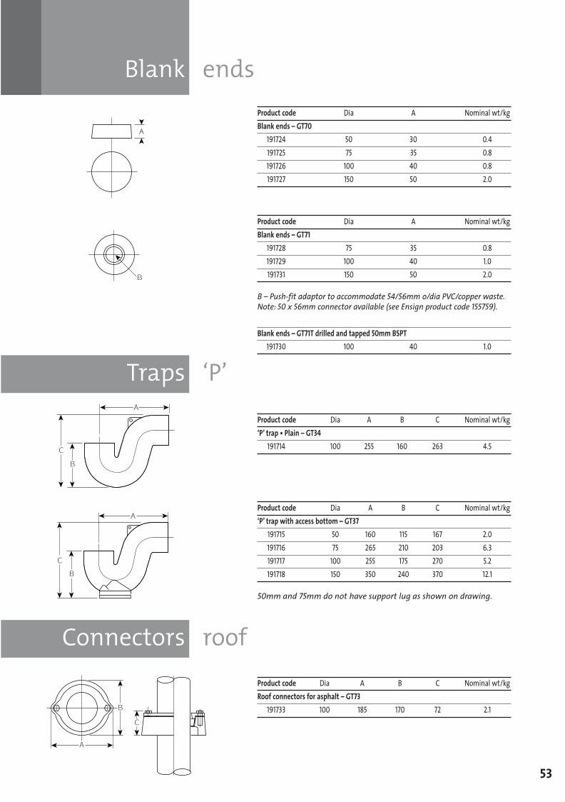
Traps ‘P’
Connectors roof
Blank ends
53
Product code Dia A Nominal wt/kgBlank ends – GT71
191728 75 35 0.8191729 100 40 1.0191731 150 50 2.0
B – Push-fit adaptor to accommodate 54/56mm o/dia PVC/copper waste.Note: 50 x 56mm connector available (see Ensign product code 155759).
Blank ends – GT71T drilled and tapped 50mm BSPT191730 100 40 1.0
Product code Dia A Nominal wt/kgBlank ends – GT70
191724 50 30 0.4191725 75 35 0.8191726 100 40 0.8191727 150 50 2.0
Product code Dia A B C Nominal wt/kg‘P’ trap • Plain – GT34
191714 100 255 160 263 4.5
Product code Dia A B C Nominal wt/kg‘P’ trap with access bottom – GT37
191715 50 160 115 167 2.0191716 75 265 210 203 6.3191717 100 255 175 270 5.2191718 150 350 240 370 12.1
50mm and 75mm do not have support lug as shown on drawing.
Product code Dia A B C Nominal wt/kgRoof connectors for asphalt – GT73
191733 100 185 170 72 2.1
SGPL_119744_Timesaver Update 2012 Pages 41 to 68_REPRO_SF:Layout 1 30/04/2012 16:36 Page 53
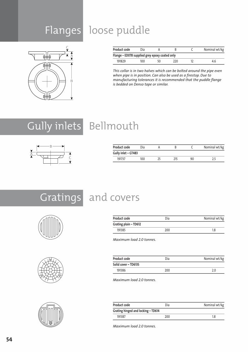
Flanges loose puddle
Gully inlets Bellmouth
Gratings and covers
54
Product code Dia A B C Nominal wt/kgFlange – ED078 supplied grey epoxy coated only
191829 100 50 220 12 4.6
This collar is in two halves which can be bolted around the pipe evenwhen pipe is in position. Can also be used as a firestop. Due tomanufacturing tolerances it is recommended that the puddle flangeis bedded on Denso tape or similar.
Product code Dia A B C Nominal wt/kgGully inlet – GT483
191737 100 25 215 90 2.5
Product code Dia Nominal wt/kgGrating plain – TD612
191385 200 1.8
Maximum load 2.0 tonnes.
Product code Dia Nominal wt/kgSolid cover – TD613S
191386 200 2.0
Maximum load 2.0 tonnes.
Product code Dia Nominal wt/kgGrating hinged and locking – TD614
191387 200 1.8
Maximum load 2.0 tonnes.
SGPL_119744_Timesaver Update 2012 Pages 41 to 68_REPRO_SF:Layout 1 30/04/2012 16:36 Page 54
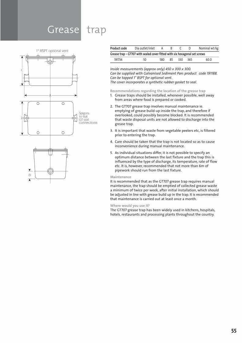
Grease trap
55
Product code Dia outlet/inlet A B C D Nominal wt/kgGrease trap – GT707 with sealed cover fitted with six hexagonal set screws
191734 50 580 85 330 365 60.0
Inside measurements (approx only) 450 x 300 x 300. Can be supplied with Galvanised Sediment Pan: product code 191188. Can be tapped 1" BSPT for optional vent.The cover incorporates a synthetic rubber gasket to seal.
Recommendations regarding the location of the grease trap1. Grease traps should be installed, whenever possible, well away from areas where food is prepared or cooked.
2. The GT707 grease trap involves manual maintenance ie. emptying of grease build-up inside the trap, and therefore if overlooked, could possibly become blocked. It is recommended that waste disposal units are not allowed to discharge into the grease trap.
3. It is important that waste from vegetable peelers etc, is filtered prior to entering the trap.
4. Care should be taken that the trap is not located so as to cause inconvenience during manual maintenance.
5. As individual situations differ, it is not possible to specify an optimum distance between the last fixture and the trap this is influenced by the type of discharge, its temperature, rate of flow etc. It is, however, recommended that not more than 6m of pipework should run from the last fixture.
MaintenanceIt is recommended that as the GT707 grease trap requires manualmaintenance, the trap should be emptied of collected grease wastea minimum of twice per week, after initial installation, which shouldbe adjusted in line with grease build up in the trap. It is recommendedthat maintenance is carried out at least once a month.
Where would you use it?The GT707 grease trap has been widely used in kitchens, hospitals,hotels, restaurants and processing plants throughout the country.
SGPL_119744_Timesaver Update 2012 Pages 41 to 68_REPRO_SF:Layout 1 30/04/2012 16:36 Page 55
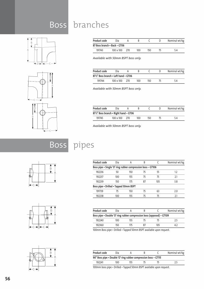
Boss branches
Boss pipes
56
Product code Dia A B C D Nominal wt/kg87 Boss branch • Back – GT06
191743 100 x 100 270 100 150 75 5.4
Available with 50mm BSPT boss only.
Product code Dia A B C D Nominal wt/kg87 1/2° Boss branch • Left hand – GT06
191744 100 x 100 270 100 150 75 5.4
Available with 50mm BSPT boss only.
Product code Dia A B C D Nominal wt/kg87 1/2° Boss branch • Right hand – GT06
191745 100 x 100 270 100 150 75 5.4
Available with 50mm BSPT boss only.
Product code Dia A B C Nominal wt/kgBoss pipe • Double ‘O’ ring rubber compression boss (opposed) – GT109
192240 100 155 75 75 2.5192360 150 175 87 105 4.2
100mm Boss pipe • Drilled • Tapped 50mm BSPT available upon request.
Product code Dia A B C Nominal wt/kgBoss pipe • Single ‘O’ ring rubber compression boss – GT106
192236 50 150 75 55 1.2192237 100 155 75 75 2.1192239 150 175 87 105 3.8
Boss pipe • Drilled • Tapped 50mm BSPT191739 75 150 75 63 2.0192238 100 155 75 75 2.1
Product code Dia A B C Nominal wt/kg90° Boss pipe • Double ‘O’ ring rubber compression boss – GT115
192241 100 155 75 75 2.5100mm boss pipe • Drilled • Tapped 50mm BSPT available upon request.
SGPL_119744_Timesaver Update 2012 Pages 41 to 68_REPRO_SF:Layout 1 30/04/2012 16:36 Page 56
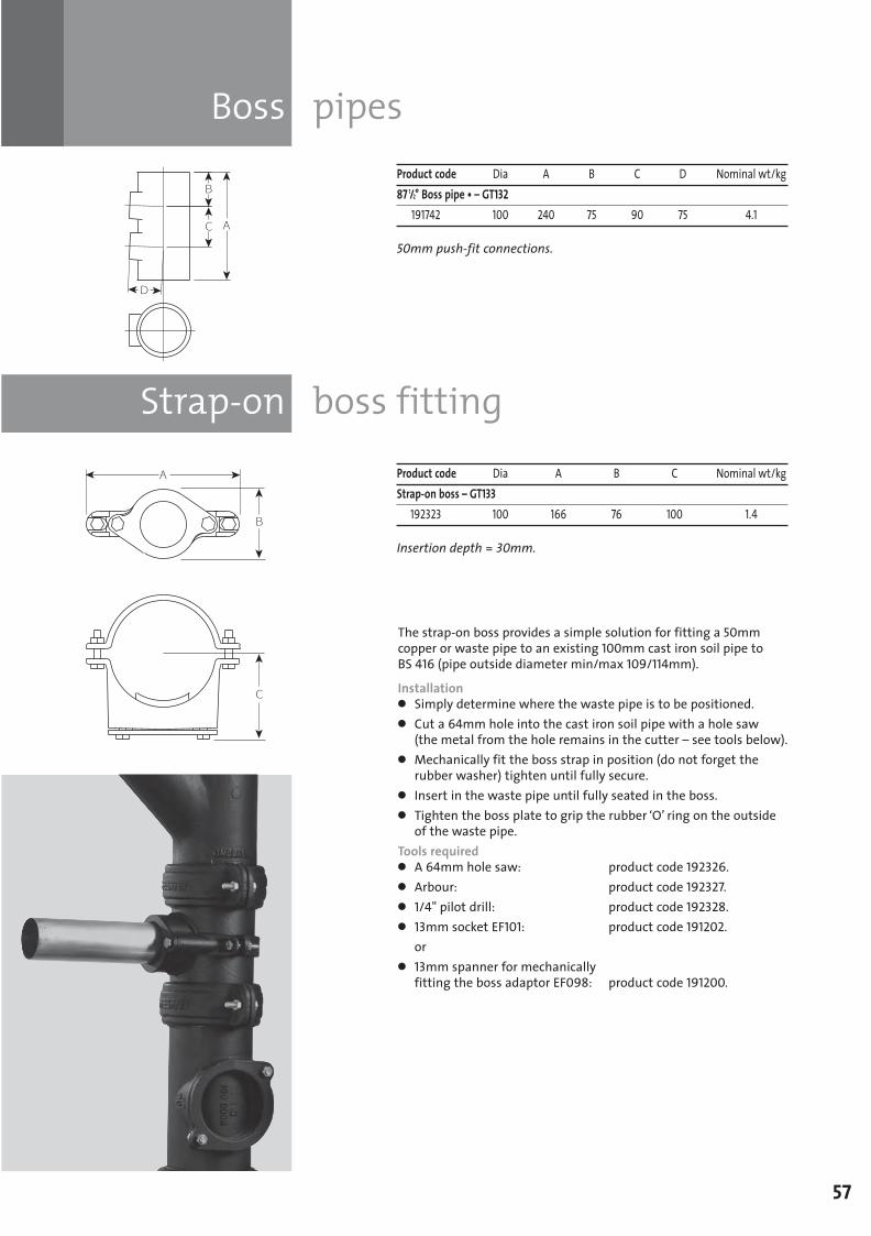
Strap-on boss fitting
Boss pipes
57
Product code Dia A B C D Nominal wt/kg87 1/2° Boss pipe • – GT132
191742 100 240 75 90 75 4.1
50mm push-fit connections.
Product code Dia A B C Nominal wt/kgStrap-on boss – GT133
192323 100 166 76 100 1.4
Insertion depth = 30mm.
The strap-on boss provides a simple solution for fitting a 50mmcopper or waste pipe to an existing 100mm cast iron soil pipe to BS 416 (pipe outside diameter min/max 109/114mm).
Installationl Simply determine where the waste pipe is to be positioned.l Cut a 64mm hole into the cast iron soil pipe with a hole saw(the metal from the hole remains in the cutter – see tools below).
l Mechanically fit the boss strap in position (do not forget therubber washer) tighten until fully secure.
l Insert in the waste pipe until fully seated in the boss.l Tighten the boss plate to grip the rubber ‘O’ ring on the outsideof the waste pipe.
Tools requiredl A 64mm hole saw: product code 192326.l Arbour: product code 192327.l 1/4" pilot drill: product code 192328.l 13mm socket EF101: product code 191202.or
l 13mm spanner for mechanically fitting the boss adaptor EF098: product code 191200.
SGPL_119744_Timesaver Update 2012 Pages 41 to 68_REPRO_SF:Layout 1 30/04/2012 16:36 Page 57
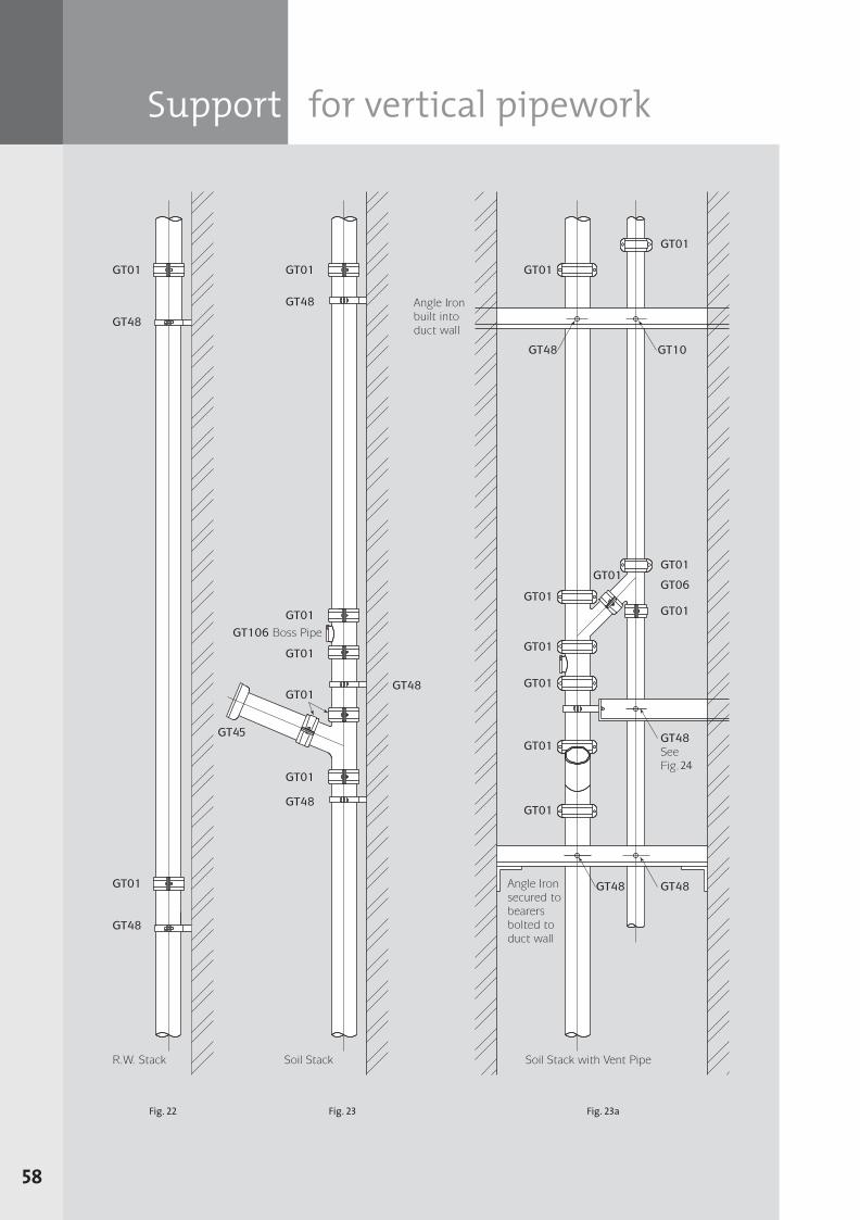
Support for vertical pipework
58
Fig. 22 Fig. 23 Fig. 23a
SGPL_119744_Timesaver Update 2012 Pages 41 to 68_REPRO_SF:Layout 1 30/04/2012 16:36 Page 58
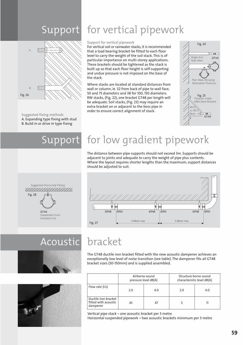
Fig. 26
Acoustic bracket
Support for low gradient pipework
Support for vertical pipeworkSupport for vertical pipeworkFor vertical soil or rainwater stacks, it is recommendedthat a load bearing bracket be fitted to each floorlevel to carry the weight of the soil stack. This is ofparticular importance on multi-storey applications.These brackets should be tightened as the stack isbuilt up so that each floor height is self-supportingand undue pressure is not imposed on the base ofthe stack.
Where stacks are located at standard distances fromwall or column, ie. 32 from back of pipe to wall face,50 and 75 diameters and 38 for 100, 150 diameters.RW stacks, (Fig. 22), one bracket GT48 per length willbe adequate. Soil stacks, (Fig. 23) may require anextra bracket on or adjacent to the boss pipe inorder to ensure correct alignment of stack.
The distance between pipe supports should not exceed 3m. Supports should beadjacent to joints and adequate to carry the weight of pipe plus contents. Where the layout requires shorter lengths than the maximum, support distancesshould be adjusted to suit.
The GT48 ductile iron bracket fitted with the new acoustic dampener achieves anexceptionally low level of noise transition (see table). The dampener fits all GT48bracket sizes (50-150mm) and is supplied assembled.
59
Suggested fixing methodsA. Expanding type fixing with studB. Build in or drive in type fixing
Vertical pipe stack – one acoustic bracket per 3 metre Horizontal suspended pipework – two acoustic brackets minimum per 3 metre
Fig. 24
Fig. 25
Fig. 27
Fig. 28
Airborne soundpressure level dB(A)
Structure borne soundcharacteristic level dB(A)
Flow rate (l/s)
Ductile iron bracketfitted with acousticdampener
2.0 4.0 2.0 4.0
45 47 5 11
SGPL_119744_Timesaver Update 2012 Pages 41 to 68_REPRO_SF:Layout 1 30/04/2012 16:37 Page 59
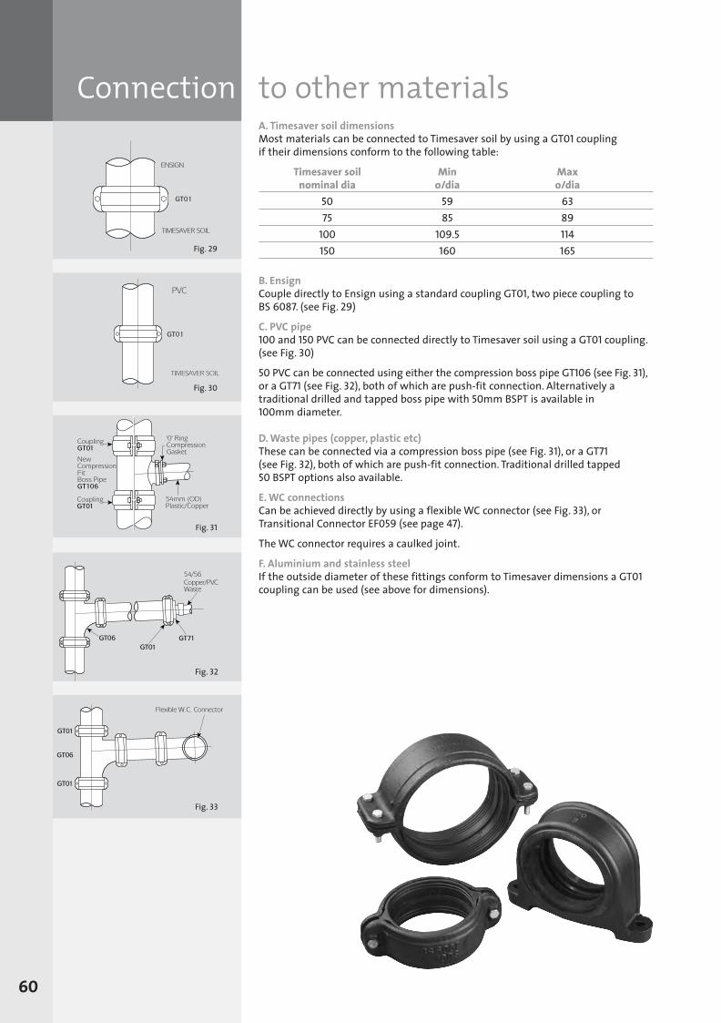
Fig. 29
Connection to other materialsA. Timesaver soil dimensionsMost materials can be connected to Timesaver soil by using a GT01 coupling if their dimensions conform to the following table:
Timesaver soil Min Maxnominal dia o/dia o/dia
50 59 6375 85 89
100 109.5 114150 160 165
B. EnsignCouple directly to Ensign using a standard coupling GT01, two piece coupling to BS 6087. (see Fig. 29)
C. PVC pipe100 and 150 PVC can be connected directly to Timesaver soil using a GT01 coupling.(see Fig. 30)
50 PVC can be connected using either the compression boss pipe GT106 (see Fig. 31),or a GT71 (see Fig. 32), both of which are push-fit connection. Alternatively atraditional drilled and tapped boss pipe with 50mm BSPT is available in 100mm diameter.
D. Waste pipes (copper, plastic etc)These can be connected via a compression boss pipe (see Fig. 31), or a GT71(see Fig. 32), both of which are push-fit connection. Traditional drilled tapped 50 BSPT options also available.
E. WC connectionsCan be achieved directly by using a flexible WC connector (see Fig. 33), orTransitional Connector EF059 (see page 47).
The WC connector requires a caulked joint.
F. Aluminium and stainless steelIf the outside diameter of these fittings conform to Timesaver dimensions a GT01coupling can be used (see above for dimensions).
60
Fig. 31
Fig. 32
Fig. 33
Fig. 30
SGPL_119744_Timesaver Update 2012 Pages 41 to 68_REPRO_SF:Layout 1 30/04/2012 16:37 Page 60
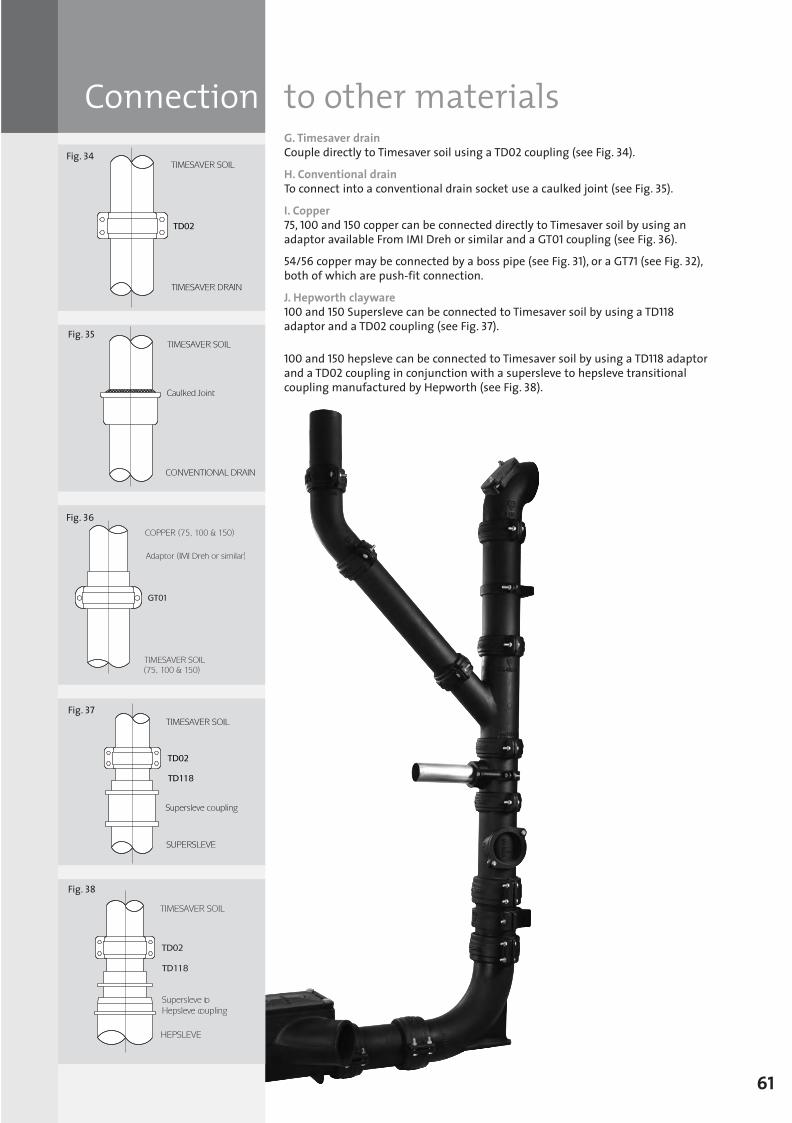
Connection to other materialsG. Timesaver drainCouple directly to Timesaver soil using a TD02 coupling (see Fig. 34).
H. Conventional drainTo connect into a conventional drain socket use a caulked joint (see Fig. 35).
I. Copper75, 100 and 150 copper can be connected directly to Timesaver soil by using anadaptor available From IMI Dreh or similar and a GT01 coupling (see Fig. 36).
54/56 copper may be connected by a boss pipe (see Fig. 31), or a GT71 (see Fig. 32),both of which are push-fit connection.
J. Hepworth clayware100 and 150 Supersleve can be connected to Timesaver soil by using a TD118adaptor and a TD02 coupling (see Fig. 37).
100 and 150 hepsleve can be connected to Timesaver soil by using a TD118 adaptorand a TD02 coupling in conjunction with a supersleve to hepsleve transitionalcoupling manufactured by Hepworth (see Fig. 38).
61
Fig. 34
Fig. 35
Fig. 36
Fig. 37
Supersleve to Hepsleve coupling
Fig. 38
SGPL_119744_Timesaver Update 2012 Pages 41 to 68_REPRO_SF:Layout 1 30/04/2012 16:37 Page 61
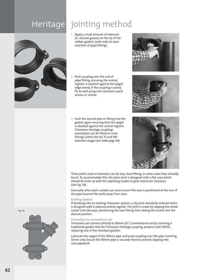
Heritage jointing method1. Apply a small amount of lubricant (ie. silicone grease) on the lip of therubber gaskets, both ends, to easeinsertion of pipe/fittings.
2. Push coupling over the end ofpipe/fitting, ensuring the centralregister is abutted against the spigotedge evenly. If the coupling is eared, fix to wall using anti-corrosion coachscrews or similar.
3. Push the second pipe or fitting into thegasket again ensuring that the spigotis abutted against the central register.Timesaver Heritage couplingseared/plain can be fitted to mostfittings within the 50, 75 and 100diameter ranges (see table page 64).
Three joints used on branches can be very close fitting, in some cases they virtuallytouch. To accommodate this, the plain joint is designed with a flat area whichshould be lined up with the adjoining socket, to give maximum clearance (see Fig. 39).
Generally when plain sockets are used, ensure flat area is positioned at the rear ofthe pipe (nearest the wall) away from view.
Existing systemsIf breaking into an existing Timesaver system, a slip joint should be ordered whichis designed with a reduced central register. The joint is made by slipping the wholesocket onto the pipe, positioning the new fitting then sliding the socket into thedesired position.
Connection to conventional soilTimesaver can connect directly to 90mm (31/2") conventional soil by inserting atraditional gasket into the Timesaver Heritage coupling, product code 156132,replacing one of the standard gaskets.
Lubricate the spigot of the 90mm pipe, and push coupling over the pipe inserting35mm only. Ensure the 90mm pipe is securely fixed to prevent slipping into new pipework.
Fig. 39
62
SGPL_119744_Timesaver Update 2012 Pages 41 to 68_REPRO_SF:Layout 1 30/04/2012 16:37 Page 62
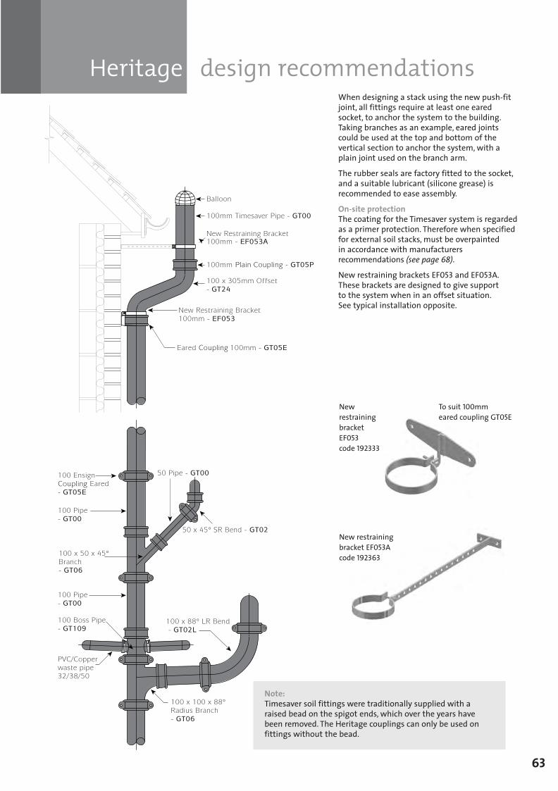
Heritage design recommendations
63
When designing a stack using the new push-fitjoint, all fittings require at least one earedsocket, to anchor the system to the building.Taking branches as an example, eared jointscould be used at the top and bottom of thevertical section to anchor the system, with aplain joint used on the branch arm.
The rubber seals are factory fitted to the socket,and a suitable lubricant (silicone grease) isrecommended to ease assembly.
On-site protectionThe coating for the Timesaver system is regardedas a primer protection. Therefore when specifiedfor external soil stacks, must be overpaintedin accordance with manufacturersrecommendations (see page 68).
New restraining brackets EF053 and EF053A.These brackets are designed to give support to the system when in an offset situation. See typical installation opposite.
New restraining bracket EF053code 192333
To suit 100mmeared coupling GT05E
New restraining bracket EF053Acode 192363
ä
ä
ä
ä
ä
ä
ä
Note:Timesaver soil fittings were traditionally supplied with araised bead on the spigot ends, which over the years havebeen removed. The Heritage couplings can only be used onfittings without the bead.
SGPL_119744_Timesaver Update 2012 Pages 41 to 68_REPRO_SF:Layout 1 30/04/2012 16:37 Page 63
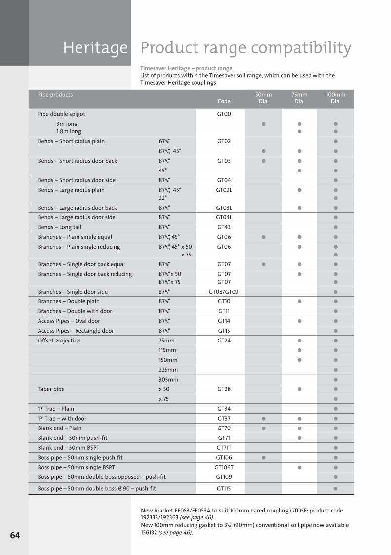
Heritage Product range compatibilityTimesaver Heritage – product rangeList of products within the Timesaver soil range, which can be used with theTimesaver Heritage couplings
64
New bracket EF053/EF053A to suit 100mm eared coupling GTO5E: product code192333/192363 (see page 46).New 100mm reducing gasket to 311/2" (90mm) conventional soil pipe now available156132 (see page 46).
Pipe products 50mm 75mm 100mmCode Dia. Dia. Dia.
Pipe double spigot GT003m long l l l
1.8m long l l
Bends – Short radius plain 67 1/2° GT02 l
87 1/2°, 45° l l l
Bends – Short radius door back 87 1/2° GT03 l l l
45° l l
Bends – Short radius door side 87 1/2° GT04 l
Bends – Large radius plain 87 1/2°, 45° GT02L l l
22° l
Bends – Large radius door back 87 1/2° GT03L l l
Bends – Large radius door side 87 1/2° GT04L l
Bends – Long tail 87 1/2° GT43 l
Branches – Plain single equal 87 1/2°, 45° GT06 l l l
Branches – Plain single reducing 87 1/2°, 45° x 50 GT06 l l
x 75 l
Branches – Single door back equal 87 1/2° GT07 l l l
Branches – Single door back reducing 87 1/2°x 50 GT07 l l
87 1/2°x 75 GT07 l
Branches – Single door side 87 1/2° GT08/GT09 l
Branches – Double plain 87 1/2° GT10 l l
Branches – Double with door 87 1/2° GT11 l
Access Pipes – Oval door 87 1/2° GT14 l l
Access Pipes – Rectangle door 87 1/2° GT15 l
Offset projection 75mm GT24 l l
115mm l l
150mm l l
225mm l
305mm l
Taper pipe x 50 GT28 l l
x 75 l
‘P’ Trap – Plain GT34 l
‘P’ Trap – with door GT37 l l l
Blank end – Plain GT70 l l l
Blank end – 50mm push-fit GT71 l l
Blank end – 50mm BSPT GT71T l
Boss pipe – 50mm single push-fit GT106 l l
Boss pipe – 50mm single BSPT GT106T l l
Boss pipe – 50mm double boss opposed – push-fit GT109 l
Boss pipe – 50mm double boss @90 – push-fit GT115 l
SGPL_119744_Timesaver Update 2012 Pages 41 to 68_REPRO_SF:Layout 1 30/04/2012 16:37 Page 64
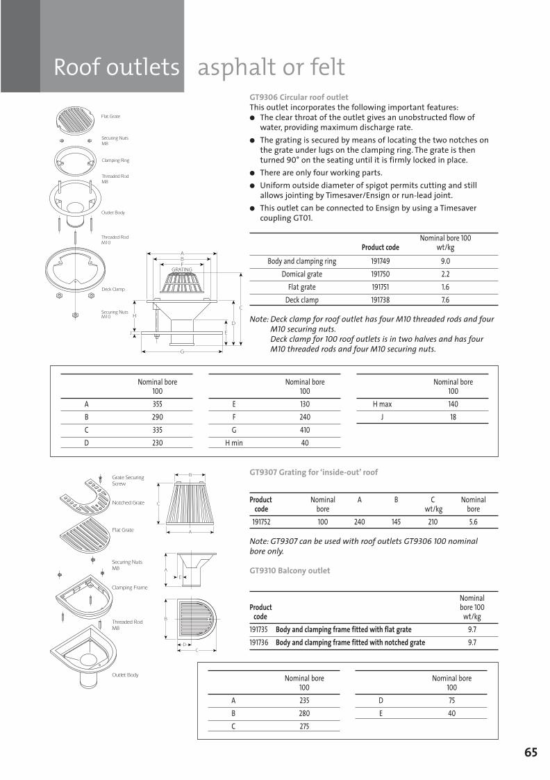
Roof outlets asphalt or felt
65
GT9306 Circular roof outletThis outlet incorporates the following important features:l The clear throat of the outlet gives an unobstructed flow ofwater, providing maximum discharge rate.
l The grating is secured by means of locating the two notches onthe grate under lugs on the clamping ring. The grate is thenturned 90° on the seating until it is firmly locked in place.
l There are only four working parts.l Uniform outside diameter of spigot permits cutting and stillallows jointing by Timesaver/Ensign or run-lead joint.
l This outlet can be connected to Ensign by using a Timesavercoupling GT01.
Nominal bore 100 Product code wt/kg
Body and clamping ring 191749 9.0Domical grate 191750 2.2Flat grate 191751 1.6Deck clamp 191738 7.6
Note: Deck clamp for roof outlet has four M10 threaded rods and fourM10 securing nuts.Deck clamp for 100 roof outlets is in two halves and has fourM10 threaded rods and four M10 securing nuts.
GT9307 Grating for ‘inside-out’ roof
Product Nominal A B C Nominalcode bore wt/kg bore
191752 100 240 145 210 5.6
Note: GT9307 can be used with roof outlets GT9306 100 nominal bore only.
GT9310 Balcony outlet
Nominal Product bore 100code wt/kg
191735 Body and clamping frame fitted with flat grate 9.7191736 Body and clamping frame fitted with notched grate 9.7
Nominal bore100
A 355B 290C 335D 230
Nominal bore100
E 130F 240G 410
H min 40
Nominal bore100
H max 140J 18
Nominal bore100
A 235B 280C 275
Nominal bore100
D 75E 40
SGPL_119744_Timesaver Update 2012 Pages 41 to 68_REPRO_SF:Layout 1 30/04/2012 16:37 Page 65
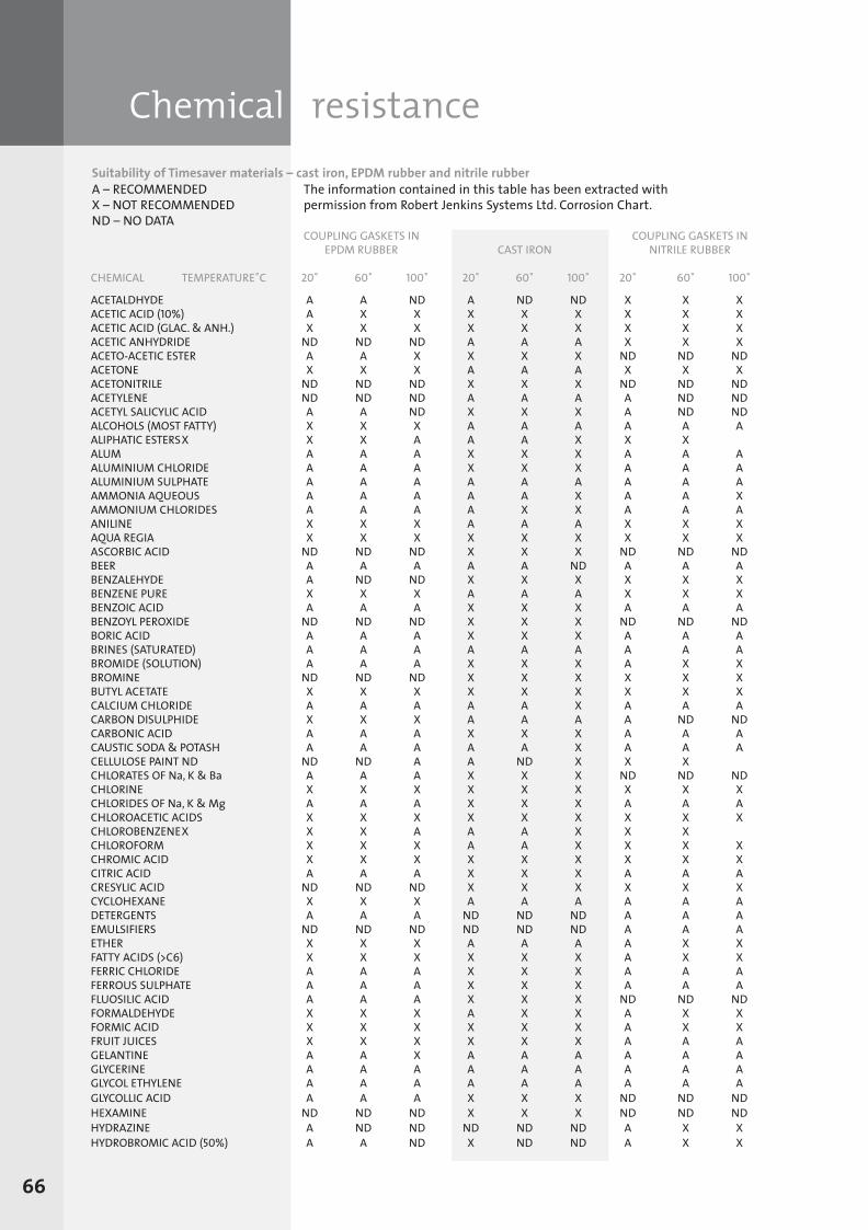
Chemical resistance
66
Suitability of Timesaver materials – cast iron, EPDM rubber and nitrile rubberA – RECOMMENDED The information contained in this table has been extracted withX – NOT RECOMMENDED permission from Robert Jenkins Systems Ltd. Corrosion Chart.ND – NO DATA
COUPLING GASKETS IN COUPLING GASKETS INEPDM RUBBER CAST IRON NITRILE RUBBER
CHEMICAL TEMPERATURE˚C 20˚ 60˚ 100˚ 20˚ 60˚ 100˚ 20˚ 60˚ 100˚
ACETALDHYDE A A ND A ND ND X X XACETIC ACID (10%) A X X X X X X X XACETIC ACID (GLAC. & ANH.) X X X X X X X X XACETIC ANHYDRIDE ND ND ND A A A X X XACETO-ACETIC ESTER A A X X X X ND ND NDACETONE X X X A A A X X XACETONITRILE ND ND ND X X X ND ND NDACETYLENE ND ND ND A A A A ND NDACETYL SALICYLIC ACID A A ND X X X A ND NDALCOHOLS (MOST FATTY) X X X A A A A A AALIPHATIC ESTERSX X X A A A X X XALUM A A A X X X A A AALUMINIUM CHLORIDE A A A X X X A A AALUMINIUM SULPHATE A A A A A A A A AAMMONIA AQUEOUS A A A A A X A A XAMMONIUM CHLORIDES A A A A X X A A AANILINE X X X A A A X X XAQUA REGIA X X X X X X X X XASCORBIC ACID ND ND ND X X X ND ND NDBEER A A A A A ND A A ABENZALEHYDE A ND ND X X X X X XBENZENE PURE X X X A A A X X XBENZOIC ACID A A A X X X A A ABENZOYL PEROXIDE ND ND ND X X X ND ND NDBORIC ACID A A A X X X A A ABRINES (SATURATED) A A A A A A A A ABROMIDE (SOLUTION) A A A X X X A X XBROMINE ND ND ND X X X X X XBUTYL ACETATE X X X X X X X X XCALCIUM CHLORIDE A A A A A X A A ACARBON DISULPHIDE X X X A A A A ND NDCARBONIC ACID A A A X X X A A ACAUSTIC SODA & POTASH A A A A A X A A ACELLULOSE PAINT ND ND ND A A ND X X XCHLORATES OF Na, K & Ba A A A X X X ND ND NDCHLORINE X X X X X X X X XCHLORIDES OF Na, K & Mg A A A X X X A A ACHLOROACETIC ACIDS X X X X X X X X XCHLOROBENZENEX X X A A A X X XCHLOROFORM X X X A A X X X XCHROMIC ACID X X X X X X X X XCITRIC ACID A A A X X X A A ACRESYLIC ACID ND ND ND X X X X X XCYCLOHEXANE X X X A A A A A ADETERGENTS A A A ND ND ND A A AEMULSIFIERS ND ND ND ND ND ND A A AETHER X X X A A A A X XFATTY ACIDS (>C6) X X X X X X A X XFERRIC CHLORIDE A A A X X X A A AFERROUS SULPHATE A A A X X X A A AFLUOSILIC ACID A A A X X X ND ND NDFORMALDEHYDE X X X A X X A X XFORMIC ACID X X X X X X A X XFRUIT JUICES X X X X X X A A AGELANTINE A A X A A A A A AGLYCERINE A A A A A A A A AGLYCOL ETHYLENE A A A A A A A A AGLYCOLLIC ACID A A A X X X ND ND NDHEXAMINE ND ND ND X X X ND ND NDHYDRAZINE A ND ND ND ND ND A X XHYDROBROMIC ACID (50%) A A ND X ND ND A X X
SGPL_119744_Timesaver Update 2012 Pages 41 to 68_REPRO_SF:Layout 1 30/04/2012 16:37 Page 66
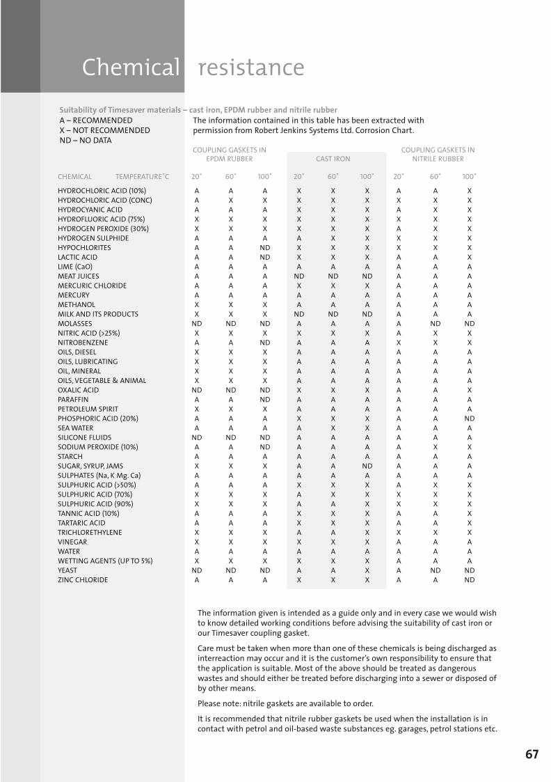
Chemical resistance
67
The information given is intended as a guide only and in every case we would wishto know detailed working conditions before advising the suitability of cast iron orour Timesaver coupling gasket.
Care must be taken when more than one of these chemicals is being discharged asinterreaction may occur and it is the customer’s own responsibility to ensure thatthe application is suitable. Most of the above should be treated as dangerouswastes and should either be treated before discharging into a sewer or disposed ofby other means.
Please note: nitrile gaskets are available to order.
It is recommended that nitrile rubber gaskets be used when the installation is incontact with petrol and oil-based waste substances eg. garages, petrol stations etc.
Suitability of Timesaver materials – cast iron, EPDM rubber and nitrile rubberA – RECOMMENDED The information contained in this table has been extracted withX – NOT RECOMMENDED permission from Robert Jenkins Systems Ltd. Corrosion Chart.ND – NO DATA
COUPLING GASKETS IN COUPLING GASKETS INEPDM RUBBER CAST IRON NITRILE RUBBER
CHEMICAL TEMPERATURE˚C 20˚ 60˚ 100˚ 20˚ 60˚ 100˚ 20˚ 60˚ 100˚
HYDROCHLORIC ACID (10%) A A A X X X A A XHYDROCHLORIC ACID (CONC) A X X X X X X X XHYDROCYANIC ACID A A A X X X A X XHYDROFLUORIC ACID (75%) X X X X X X X X XHYDROGEN PEROXIDE (30%) X X X X X X A X XHYDROGEN SULPHIDE A A A A X X X X XHYPOCHLORITES A A ND X X X X X XLACTIC ACID A A ND X X X A A XLIME (CaO) A A A A A A A A AMEAT JUICES A A A ND ND ND A A AMERCURIC CHLORIDE A A A X X X A A AMERCURY A A A A A A A A AMETHANOL X X X A A A A A AMILK AND ITS PRODUCTS X X X ND ND ND A A AMOLASSES ND ND ND A A A A ND NDNITRIC ACID (>25%) X X X X X X A X XNITROBENZENE A A ND A A A X X XOILS, DIESEL X X X A A A A A AOILS, LUBRICATING X X X A A A A A AOIL, MINERAL X X X A A A A A AOILS, VEGETABLE & ANIMAL X X X A A A A A AOXALIC ACID ND ND ND X X X A A XPARAFFIN A A ND A A A A A APETROLEUM SPIRIT X X X A A A A A APHOSPHORIC ACID (20%) A A A X X X A A NDSEA WATER A A A A X X A A ASILICONE FLUIDS ND ND ND A A A A A ASODIUM PEROXIDE (10%) A A ND A A A A X XSTARCH A A A A A A A A ASUGAR, SYRUP, JAMS X X X A A ND A A ASULPHATES (Na, K Mg. Ca) A A A A A A A A ASULPHURIC ACID (>50%) A A A X X X A X XSULPHURIC ACID (70%) X X X A X X X X XSULPHURIC ACID (90%) X X X A A X X X XTANNIC ACID (10%) A A A X X X A A XTARTARIC ACID A A A X X X A A XTRICHLORETHYLENE X X X A A X X X XVINEGAR X X X X X X A A AWATER A A A A A A A A AWETTING AGENTS (UP TO 5%) X X X X X X A A AYEAST ND ND ND A A X A ND NDZINC CHLORIDE A A A X X X A A ND
SGPL_119744_Timesaver Update 2012 Pages 41 to 68_REPRO_SF:Layout 1 30/04/2012 16:37 Page 67
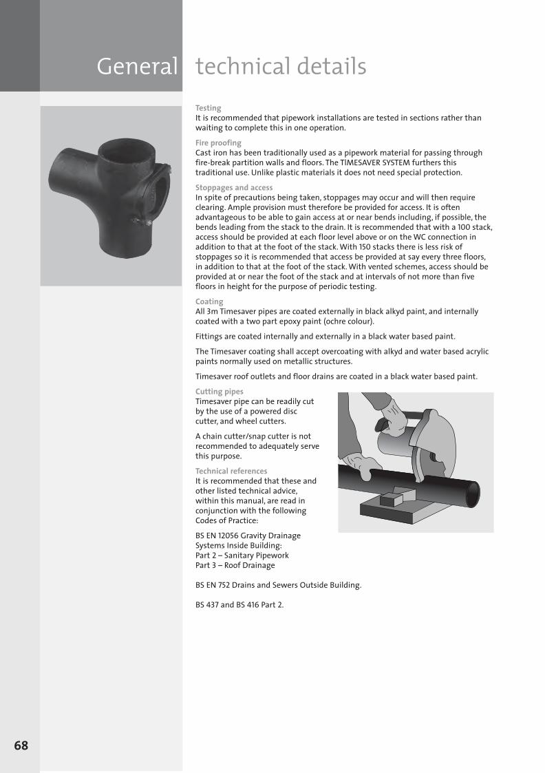
TestingIt is recommended that pipework installations are tested in sections rather thanwaiting to complete this in one operation.
Fire proofingCast iron has been traditionally used as a pipework material for passing throughfire-break partition walls and floors. The TlMESAVER SYSTEM furthers thistraditional use. Unlike plastic materials it does not need special protection.
Stoppages and accessIn spite of precautions being taken, stoppages may occur and will then requireclearing. Ample provision must therefore be provided for access. It is oftenadvantageous to be able to gain access at or near bends including, if possible, thebends leading from the stack to the drain. It is recommended that with a 100 stack,access should be provided at each floor level above or on the WC connection inaddition to that at the foot of the stack. With 150 stacks there is less risk ofstoppages so it is recommended that access be provided at say every three floors,in addition to that at the foot of the stack. With vented schemes, access should beprovided at or near the foot of the stack and at intervals of not more than fivefloors in height for the purpose of periodic testing.
CoatingAll 3m Timesaver pipes are coated externally in black alkyd paint, and internallycoated with a two part epoxy paint (ochre colour).
Fittings are coated internally and externally in a black water based paint.
The Timesaver coating shall accept overcoating with alkyd and water based acrylicpaints normally used on metallic structures.
Timesaver roof outlets and floor drains are coated in a black water based paint.
Cutting pipesTimesaver pipe can be readily cutby the use of a powered disccutter, and wheel cutters.
A chain cutter/snap cutter is notrecommended to adequately servethis purpose.
Technical referencesIt is recommended that these andother listed technical advice,within this manual, are read inconjunction with the followingCodes of Practice:
BS EN 12056 Gravity DrainageSystems Inside Building:Part 2 – Sanitary PipeworkPart 3 – Roof Drainage
BS EN 752 Drains and Sewers Outside Building.
BS 437 and BS 416 Part 2.
General technical details
68
SGPL_119744_Timesaver Update 2012 Pages 41 to 68_REPRO_SF:Layout 1 30/04/2012 16:37 Page 68
Note: Our policy of continuing product development and improvement necessitates that we reserve
the right to modify designs shown in this brochure without prior notice.
Head OfficeLows Lane, Stanton-by-Dale, Ilkeston,Derbyshire DE7 4QUTel: 0115 930 5000 Fax: 0115 932 9513
Email: [email protected]
www.saint-gobain-pam.co.uk (Click on Soil and Drain)
69
Standard specificationTimesaver standard specification and clauses1.1 Above ground soil, waste, vent and rainwater pipework.1.2 Cast iron pipes and fittings
a) The systems shall be designed and installed in accordance with BS EN 12056 code of practice forgravity drainage systems inside buildings and therelevant sections of the Building Regulations.
b) Soil, waste, vent and rainwater pipework of nominaldiameters, 50mm to 150mm shall be installed usingcast iron socketless pipe and fittings which fullycomply with requirements of product standard BS 416 part 2 with Kitemark third party approval.
Bracketsc) Pipework shall be supported true to line by methods
strictly in accordance with the manufacturer’srecommendations. Proprietary adjustable ductileiron hanging brackets such as GT48 shall be used orbrackets as recommended by the manufacturer’sstandard guidelines.
d) If required, soil, waste, vent and rainwater pipeworkshall be supported by acoustic brackets that ensurethe pipework will not exceed 47dB (A) airbornenoise and 11dB (A) structure-borne noise at 4 L/s(litres per second), without insulation as recommendedby the manufacturer’s standard guidelines.
Jointing Standard couplingse) Pipes and fittings shall be jointed by two part ductile
iron couplings capable of withstanding up to 5bar(accidental static water pressure) when suitablyrestrained with support brackets. Couplings to befitted with EPDM rubber gasket as supplied.
f) Couplings shall be fitted with steel continuity clips(supplied separately) if equipotential bonding(earthing) has been specified. Coupling colour shallmatch the pipes and fittings.
Push-fit Heritage couplings g) Pipes and fittings shall be jointed by Timesaver
Heritage push-fit couplings incorporating 2 EPDMgaskets that give the appearance of a traditionalsocket as depicted in BS 416 part 1.
Fittingsh) Where possible all 88 degree branches shall be radius
curve entry (conforming to BS EN 12056-2:2000).i) Small diameter waste pipes in plastic or copper to
be connected to the main soil pipework using eithermechanical compression-fit or BSP threaded bosspipes or blank ends.
Cutting pipesj) Where pipes are cut on site, ends shall be cut clean
and square with all burrs removed. In most cases itis not necessary to re-coat the pipe ends with ‘touchup paint’. However, where there may be aggressivematerials passing through the drainage system (i.e.Coca-Cola; acid rain; acids or strong alkaline orsimilar substances), it is necessary to protect the cutends of the pipework to the same standard as theinternal coating of the pipe. (as recommended bythe manufacturer.
Coatingk) 3 metre pipes shall be externally coated with a black
alkyd primer paint. Internally coated with a two-partepoxy coating, ochre in colour, with an averagethickness of 130 microns.
l) 1.8 metre (6ft) Heritage pipes shall be coated internallyand externally with a black water based paint.
m) Fittings/couplings/brackets shall be protectedinternally and externally with a black water based paint.
Timesaver standard specification1.1 Below ground buried foul and stormwater pipework.1.2 Cast iron pipes and fittings
a) The systems shall be designed and installed inaccordance with BS EN 12056 code of practice forgravity drainage systems inside buildings, BS EN 752-1for drain and sewer systems outside buildings andthe relevant sections of the Building Regulations.
b) Foul and stormwater pipework of nominal diameters,100, 150 and 225mm shall be installed using cast ironsocketless pipe and fittings which fully comply withall requirements of product standard BS 437 withkitemark third party approval.
Bracketsc) Pipework shall be supported true to line by methods
strictly in accordance with the manufacturer’srecommendations. Proprietary adjustable ductileiron hanging brackets as TD 640 shall be used orbrackets as recommended by the manufacturer’sstandard guidelines.
Jointing Standard couplingsd) Pipes and fittings shall be jointed by ductile iron
couplings capable of withstanding up to 5bar(accidental static water pressure) when suitablyrestrained with support brackets. Coupling colourshall match the pipes and fittings, and incorporatestainless steel socket cap screws and nuts wax coated.
Fittingse) Junctions between pipes should use the proprietary
cast iron chamber, or standard branch type fittingsas recommended by the manufacturer.
Cutting pipesf) Where pipes are cut on site, ends shall be cut clean
and square with all burrs removed. In most cases itis not necessary to re-coat the pipe ends with ‘touch-up paint’. However, where there may be aggressivematerials passing through the drainage system (i.e.Coca-Cola; acid rain; acids or strong alkaline orsimilar substances), it is necessary to protect the cutends of the pipework to the same standard as theinternal coating of the pipe (as recommended by the manufacturer).
Coatingg) Pipes shall be externally coated with a black alkyd
primer paint. Internally coated with a two-partepoxy coating, ochre in colour, with an averagethickness of 250 microns.
h) Fittings/couplings/brackets shall be protectedinternally and externally with a black water based paint.
SGPL_119744_Timesaver Update 2012 COVER_REPRO_SF:Layout 1 30/04/2012 16:42 Page 3
Timesaver
Specifier’s ManualCOMPLETE CAST IRON
DRAINAGE SYSTEMS FOR
ABOVE AND BELOW GROUND
INCLUDING ROOF OUTLETS
AND FLOOR DRAINS
BS 437BS 416
April 2012
Uniclass G5811 : L7312
CI/SfB
(52)
visit: www.saint-gobain-pam.co.ukThe information given in this literature is, to the best of our knowledge, correct at the time of going to print. However, Saint-Gobain PAM isconstantly looking at ways of improving their products and services and therefore reserve the right to change, without prior notice, any of thedata contained in this publication. Any orders placed will be subject to our Standard Conditions of Sale, available on request.
© 2012 Saint-Gobain PAM
Please visit our website:www.saint-gobain-pam.co.ukto download electronic version or to request hard copies of any of our brochures
Technical EnquiriesTel: +44 (0)1952 262529Fax: +44 (0)1952 262592Email: [email protected]
Sales EnquiriesTel: +44 (0)115 930 0681Fax: +44 (0)115 930 0648Email: [email protected]
Head OfficeLows LaneStanton-by-DaleIlkestonDerbyshireDE7 4QUTel: +44 (0)115 930 5000Fax: +44 (0)115 932 9513
Prin
ted
on ch
lorin
e-fr
ee, e
nviro
nmen
tally
frie
ndly
pap
er fr
om su
stai
nabl
e fo
rest
stoc
k.
Quality Assurance Quality Management Systems BS EN ISO 9001:2008(Registered firm: 12908)
Environmental StandardEnvironmental Management Systems BS EN ISO 14001:2004
Your local stockist is:
Natural™A range of potable water pipeline products available DN80 toDN800 with a new revolutionary system of external protection,fully compliant with the requirements of BS EN 545.
Large diameter water pipesLarge diameter water pipeline products available DN900 toDN2000, fully compliant with the requirements of BS EN 545.
Integral and Integral Plus™A complete range of sewerage pipeline products available from DN80 to DN2000, fully compliant with the requirements of BS EN 598.
DirectionalA ductile iron pipe solution for horizontal directional drillingapplications. Available from DN100 to DN700 and fullycompliant with BS 545 and BS 598.
Couplings and flange adaptorsAccommodating a wide range of external diameters and pipematerials in accordance with British, European Standards andISO 9001 requirements. A diversified range from wide tolerancefittings to dedicated products.
ValvesA comprehensive range of valves and accessories suitable forwater and sewerage applications. All valves are supplied incompliance with WRAS requirements where applicable, andmanufactured in accordance with ISO 9001.
• Gate valves, resilient and metal faced DN50 to DN300• Non return valves DN80 to DN300• Tidal flap valves DN80 to DN600• Air valves• Fire hydrants• Butterfly valves DN50 to DN2000• Control valves
RapidFlange™A business unit dedicated to offering fast and flexible service toM&E and pump market sectors – specialising in providing highquality flanged products and offering technical support andrapid response.
Induct Plus™An installation accreditation scheme, designed to give peace ofmind and confidence to water utilities and contractors in theknowledge that the ductile iron pipeline that they have purchasedwill be installed effectively and in its optimum condition.
Ensign™Cast iron above and below ground drainage system BSI Kitemarkapproved to BS EN 877. Used for soil and waste, rainwater,suspended, buried and bridge drainage applications, providinglifetime service for commercial and public buildings.
Ensign EEZI-FIT™A new range of cast iron push-fit fittings and couplings in 100, and 150mm diameter, Kitemarked to BS EN 877 for gravity sanitary installations.
Timesaver™Cast iron above ground system BSI Kitemark approved to BS 416part 2, used for soil and waste refurbishment, and external soilstacks for traditional appearance. Cast iron below ground systemBSI Kitemark approved to BS 437, favoured for under buildingdrainage, and unstable ground conditions due to its superiorstrength performance.
Classical – Classical Plus™Cast iron rainwater and gutter systems to BS 460 BBA certified.Eight gutter profiles and circular, square and rectangulardownpipes systems supplied in a black primer coat. Classical Plus isa standard range of gutters and downpipes available in a factoryapplied semi-gloss black finished coat for immediateinstallation.
EPAMS™A complete syphonic rainwater system, consisting of steelsyphonic roof outlets and cast iron pipework to BS EN 877 BBA certified.
Access covers and gratingsA comprehensive range of ductile iron access covers andgratings. For high performance products which meet theincreasing demands from traffic to a purpose designed range forlow density applications, Saint-Gobain PAM access coverproducts provide targeted solutions for the key civil engineering,utility and infrastructure sectors.
Other products and services available from Saint-Gobain PAM UK:
SGPL_119744_Timesaver Update 2012 COVER_REPRO_SF:Layout 1 30/04/2012 16:42 Page 1