Embed Size (px)
Citation preview
THE JOURNAL OF VISUALIZATION AND COMPUTER ANIMATIONJ. Visual. Comput. Animat. 9, 53–63 (1998)
Tighter Error Bounds and Weighted ErrorMetrics for Hierarchical Radiosity
chin-chen chang and zen-chung shih*Department of Computer and Information Science, National Chiao Tung University,
Hsinchu, Taiwan 30010, Republic of China
SUMMARY
In this paper we first derive a tighter error bound on form factors as a subdivision criterion forthe hierarchical radiosity algorithm. Such an error bound can reduce more unnecessary links andimprove the performance of the hierarchical radiosity algorithm to meet a user-specified errortolerance. We then propose a weighted error metric in form factor computation such that moreeffort is automatically applied to shadow boundaries. Evaluating form factors along shadowboundaries with a higher degree of precision should enhance the quality of human perception.Using the proposed tighter error bound on the weighted error metric, we not only improve theperformance but also increase the accuracy of the hierarchical radiosity algorithm. 1998 JohnWiley & Sons, Ltd.
key words: global illumination; error analysis; radiosity; visibility; shadow
1. INTRODUCTION
Radiosity provides a solution for the global illumination problem within a closedenvironment consisting of ideal diffuse reflectors and emitters. Radiosity approachescan only produce approximate results, thereby accounting for the existence of errorsin the radiosity solution. If the error bound is too conservative, it will cause moreunnecessary subdivisions in the radiosity algorithm to meet a user-specified errortolerance. Thus the computational cost becomes very expensive. Moreover, if theerror is large, it will cause unacceptable radiosity soolutions. Therefore reliable errorbounds and accurate error estimations are important for radiosity.
Up to now there have been several works devoted to the bound and error estimatefor radiosity. Cohenet al.1 proposed a two-level hierarchy known as thesubstructur-ing techniquefor radiosity. The patches, e.g. those along shadow boundaries, thatexhibit a high radiosity gradient are subdivided further to yield accurate solutions.Hanrahanet al.2 generalized the two-level hierarchy to amultilevel hierarchyfromAppel’s algorithm for resolving theN-body problem.3 They computed an approximate
* Correspondence to: Zen-Chung Shih, Department of Computer and Information Science, National Chiao TungUniversity, Hsinchu, Taiwan 30010, Republic of China.E-mail: zcshihKcc.nctu.edu.tw
CCC 1049–8907/98/020053–11$17.50 Received 31 May 1996 1998 John Wiley & Sons, Ltd. Revised 17 July 1997 and 23 Sept 1997
54 c.-c. chang and z.-c. shih
upper bound on the form factor and used a brightness-weighted refinement strategyas a criterion for determining the level in the hierarchy at which two patches caninteract. Smitset al.4 proposed animportance-drivenradiosity approach that efficientlycomputes the view-dependent global solutions. Their algorithm refines any interactionif its estimated error exceeds the given error tolerance. Smitset al.5 presented analgorithm for accelerating the hierarchical radiosity in complex environments byclustering objects. They used bounds on the potential error to transfer energy betweenobjects. Arvo et al.6 characterized possible sources of error in global illuminationand derived bounds for each distinct category. To obtain better solutions, each sourceof an error should be considered. Lischinskiet al.7 proposed an approach to determinea posteriori bounds and estimates for local and total error of radiosity. Theiralgorithm considered the propagation of errors due to interreflections and providedconservative error bounds. Pellegrini8 introduced a new characterization of formfactors based on concepts from integral geometry. He proposed a new Monte Carloalgorithm to compute approximations of form factors with an error boundeda prioriin an occluded polyhedral environment. Sillion and Drettakis9 proposed afeature-based error metricfor radiosity. They introduced an approach to controlling errorin hierarchical clustering algorithms.
The shadow provides an important cue for human perception of image quality.An inaccurate evaluation of the visibility leads to errors in the shadow and sub-sequently affects the image quality. Owing to these reasons, the shadow should beaccurately dealt with. To compute shadows efficiently and accurately, severalapproaches have been proposed.10–15 However, most available methods are empiricaland do not consider the reflection model. In fact, a Watt and Watt16 indicate, theshadow is a local decrement in diffuse light because of the blocking of directillumination. Shadows can be incorporated into the radiosity method because theyare part of the diffuse interaction problem.
In this paper we first derive a better error bound for the hierarchical radiosityalgorithm, that differs from the usual bound by a factor of.. Such an error boundcan reduce more unnecessary links and improve the performance of the hierarchicalradiosity algorithm to meet a user-specified error tolerance. However, this approachwill decrease the accuracy of the shadow and thus affect the user’s perception ofimage quality. Therefore we propose a weighted error metric in form factor compu-tation to increase the accuracy of radiosity along shadow boundaries and penumbras.We define a weighting function in this metric, in which different areas may havedifferent weights. Shadow boundaries may obtain more weights than others. Radiosi-ties along shadow boundaries are computed with a higher degree of precision, whilethose of others are computed normally. Using our proposed tighter error bound onthe weighted error metric, we improve the performance and enhance the accuracyof the hierarchical radiosity algorithm.
The rest of this paper is organized as follows. In Section 2 we derive a tightererror bound on form factors. In Section 3 we discuss the weighted error metric inform factor computation. Analysis and comparison are displayed in Section 4. Finally,conclusions and future work are given in Section 5.
2. TIGHTER ERROR BOUNDS ON FORM FACTORSThe form factor from a pointx on patchPi to patchPj is given by the area integralwith the kernel functionk(x,y),
1998 John Wiley & Sons, Ltd. J. Visual. Comput. Animat.9, 53–63 (1998)
55error bounds for hierarchical radiosity
Fij 5 EyPPj
k(x,y)dy
where y is a point onPj, and
k(x,y) 5cosuicosuj
pr2 v(x,y)
where r is the distance betweenx and y; ui is the angle formed by the normal ofthe differential area atx and the line connectingx and y; uj is the angle formed bythe normal of the differential area aty and the line connectingx and y; and v(x,y)is the visibility function, which is one ifx and y are mutually visible, andzero otherwise.
We follow the notation of Smitset al.5 in computing the form factor bounds. Letthe maximum, minimum and average values of a functionf over the domainA 3 Bbe defined by
fA,B ; maxxPA,yPB
f(x,y)
fA,B ; minxPA,yPB
f(x,y)
and
k f lA.B ; avgxPA,yPB
f(x,y)
respectively. The approximate form factorFˆ
ij is given by
Fˆ
ij 5 k k lA,B · Aj
where Aj is the area ofPj. A conservative error bound (C E B) on the form factorin L` norm can be obtained by bounding the difference between the maximum andminimum values of the form factor.5 That is, we have that
iFij 2 Fˆ
iji` # (kPi,Pj· Aj 2 kPi,Pj
· Aj)
holds.However, such an error bound will produce many unnecessary links and cause
too much computational cost for the hierarchical radiosity algorithm to meet theuser-specified error tolerance. Therefore the development of a tighter error boundis needed.7,17
We define themiddle valueof a function f over the domainA 3 B as
[f]A,B ;12 S max
xPA,yPBf(x,y) 1 min
xPA,yPBf(x,y)D
The approximate form factorF˜
ij is given by
1998 John Wiley & Sons, Ltd. J. Visual. Comput. Animat.9, 53–63 (1998)
56 c.-c. chang and z.-c. shih
F˜
ij 5 EyPPj
[k]Pi,Pjdy
5 EyPPj
12 SkPi,Pj
1 kPi,PjDdy
512 SkPi,Pj
· Aj 1 kPi,Pj· AjD
We can derive a tighter error bound (T E B) on the form factor inL` norm as
iFij 2 F˜
iji` 5 ISEyPPj
k(x,y)dy 2 EyPPj
[k]Pi,PjdyDI
`
5 IEyPPj
Sk(x,y) 2kPi,Pj
1 kPi,Pj
2 D dyI`
5 maxxPPi |EyPPj
Sk(x,y) 2kPi,Pj
1 kPi,Pj
2 D dy|# E
yPPj
kPi,Pj2 kPi,Pj
2dy
512
(kPi,Pj· Aj 2 kPi,Pj
· Aj)
This error bound depends strongly on the value ofF˜
ij and is tighter than theC E B.
3. A WEIGHTED ERROR METRIC
The shadow plays an important role in determining the human perception of imagequality. In this section we propose a weighted error metric in form factor computationsuch that more effort is automatically applied to shadow boundaries.
3.1. Shadows
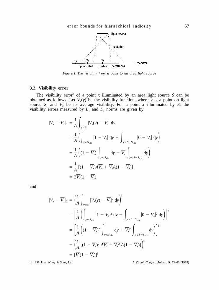
An area light source casting light onto an object will result in a shadow consistingof the penumbra and the umbra. The penumbra is the area receiving part of thelight from the area light source, while the umbra is the region receiving no lightfrom the area light source directly. Consider Figure 1. Pointx1, unable to perceivethe area light source, is in the umbra. Pointx2, perceiving part of the area lightsource, is in the penumbra. Pointx3, perceiving the entire area light source, is notin the shadow. Therefore whether a point is in the region of shadow or not dependson its visibility from the area light source. An inaccurate calculation of the visibilitywill cause errors in the shadow.
1998 John Wiley & Sons, Ltd. J. Visual. Comput. Animat.9, 53–63 (1998)
57error bounds for hierarchical radiosity
Figure 1. The visibility from a point to an area light source
3.2. Visibility error
The visibility error9 of a point x illuminated by an area light sourceS can beobtained as follows. LetVx(y) be the visibility function, wherey is a point on lightsource S, and Vx be its average visibility. For a pointx illuminated by S, thevisibility errors measured byL1 and L2 norms are given by
iVx 2 Vxi1 51A E
yPS
uVx(y) 2 Vxu dy
51A SE
yPSvis
u1 2 Vxu dy 1 EyPS2Svis
u0 2 Vxu dyD5
1A S(1 2 Vx) E
yPSvis
dy 1 Vx EyPS2Svis
dyD5
1A
[(1 2 Vx)AVx 1 VxA(1 2 Vx)]
5 2Vx(1 2 Vx)
and
iVx 2 Vxi2 5 S1A E
yPS
uVx(y) 2 Vxu2 dyD.
5 F1A SE
yPSvis
u1 2 Vxu2 dy 1 EyPS2Svis
u0 2 Vxu2 dyDG.
5 F1A S(1 2 Vx)2 E
yPSvis
dy 1 Vx2 E
yPS2Svis
dyDG.
5 S1A
[(1 2 Vx)2 AVx 1 Vx2 A(1 2 Vx)]D.
5 [Vx(1 2 Vx)].
1998 John Wiley & Sons, Ltd. J. Visual. Comput. Animat.9, 53–63 (1998)
58 c.-c. chang and z.-c. shih
respectively, whereA is the area ofS, Svis is the region ofS that is visible fromx,and S2 Svis depicts the region ofS that is invisible fromx. Hence both estimatesreveal that the error on visibility for a point illuminated by an area light source isdependent on the termVx(1 2 Vx). Consequently, a partially visible case leads to anerror. Radiosity of the penumbra region needs more accurate computation to achieverealistic images.
3.3. A weighted error metric based on visibility
We define a weight for each point in three-dimensional space. When radiositiesare evaluated, much emphasis is put on regions with higher weights to achieve moreaccurate solutions.
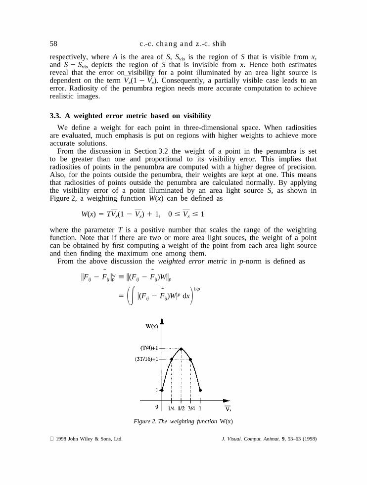
From the discussion in Section 3.2 the weight of a point in the penumbra is setto be greater than one and proportional to its visibility error. This implies thatradiosities of points in the penumbra are computed with a higher degree of precision.Also, for the points outside the penumbra, their weights are kept at one. This meansthat radiosities of points outside the penumbra are calculated normally. By applyingthe visibility error of a point illuminated by an area light sourceS, as shown inFigure 2, a weighting functionW(x) can be defined as
W(x) 5 TVx(1 2 Vx) 1 1, 0 # Vx # 1
where the parameterT is a positive number that scales the range of the weightingfunction. Note that if there are two or more area light souces, the weight of a pointcan be obtained by first computing a weight of the point from each area light sourceand then finding the maximum one among them.
From the above discussion theweighted error metricin p-norm is defined as
iFij 2 F˜
ijiwp ; i(Fij 2 F
˜ij)Wip
5 SE u(Fij 2 F˜
ij)Wup dxD1/p
Figure 2. The weighting functionW(x)
1998 John Wiley & Sons, Ltd. J. Visual. Comput. Animat.9, 53–63 (1998)
59error bounds for hierarchical radiosity
We can use the concept discussed in Section 2 to derive an error bound on theweighted error metric as a subdivision criterion for the hierarchical radiosity algor-ithm. To compare theC E B, we will use the`-norm in the rest of this paper. Aconservative error bound (C E B W) on the weighted error metric in -norm can beobtained as
iFij 2 F˜
ijiw` ; i(Fij 2 F
˜ij)Wi`
5 maxxPPi
u(Fij 2 F˜
ij)Wu
# maxxPPi
u(Fij 2 F˜
ij)u · maxxPPi
uWu
# (kPi,Pj· Aj 2 kPi,Pj
· Aj) · WPi,S
Besides, a tighter error bound (T E B W) on the weighted error metric in -normcan be obtained as
iFij 2 F˜
ijiw` #
12( kPi,Pj
· Aj 2 kPi,Pj· Aj) · WPi,S
4. ANALYSIS AND COMPARISON
We compare the hierarchical radiosity algorithm2 using the T E B, C E B W andT E B W with that using theC E B. All experiments are implemented on an SGIworkstation with 200 MHz R4400 CPU. We use the point-sampling-based technique5
to calculate form factor bounds and the upper bound of the weighting function. Inour implementation we use 16 samples for each pair of patches. The assignment ofthe parameterT in the weighting function depends on the desired accuracy of thepenumbra and the given environment. In our implementation we select 25, 35 and45 for T. We use the RMS error to measure the quality of the radiosity solutionsof penumbra regions by using a 643 64 mesh on the receiver (floor). The referencesolution is obtained by the hierarchical radiosity algorithm using theC E B with avery high precision (the user-specified error toleranceFeps5 1025).
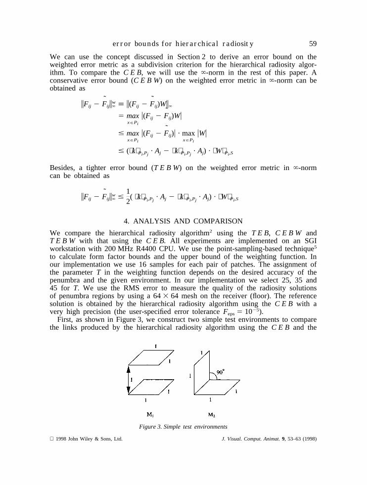
First, as shown in Figure 3, we construct two simple test environments to comparethe links produced by the hierarchical radiosity algorithm using theC E B and the
Figure 3. Simple test environments
1998 John Wiley & Sons, Ltd. J. Visual. Comput. Animat.9, 53–63 (1998)
60 c.-c. chang and z.-c. shih
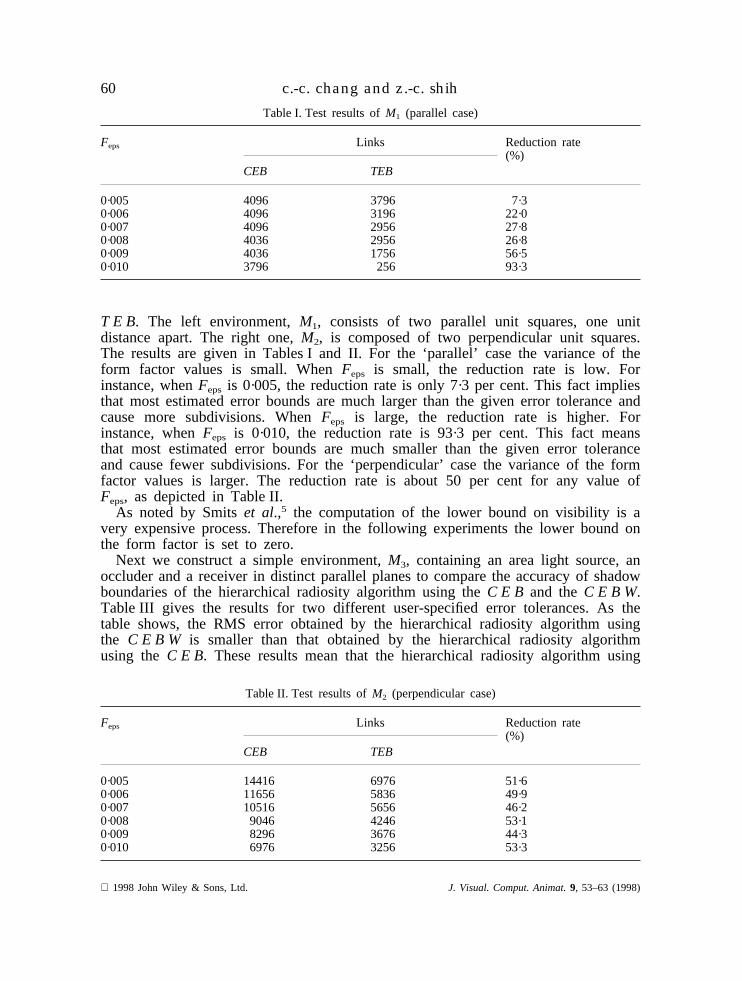
Table I. Test results ofM1 (parallel case)
Feps Links Reduction rate(%)
CEB TEB
0·005 4096 3796 7·30·006 4096 3196 22·00·007 4096 2956 27·80·008 4036 2956 26·80·009 4036 1756 56·50·010 3796 256 93·3
T E B. The left environment,M1, consists of two parallel unit squares, one unitdistance apart. The right one,M2, is composed of two perpendicular unit squares.The results are given in Tables I and II. For the ‘parallel’ case the variance of theform factor values is small. WhenFeps is small, the reduction rate is low. Forinstance, whenFeps is 0·005, the reduction rate is only 7·3 per cent. This fact impliesthat most estimated error bounds are much larger than the given error tolerance andcause more subdivisions. WhenFeps is large, the reduction rate is higher. Forinstance, whenFeps is 0·010, the reduction rate is 93·3 per cent. This fact meansthat most estimated error bounds are much smaller than the given error toleranceand cause fewer subdivisions. For the ‘perpendicular’ case the variance of the formfactor values is larger. The reduction rate is about 50 per cent for any value ofFeps, as depicted in Table II.
As noted by Smitset al.,5 the computation of the lower bound on visibility is avery expensive process. Therefore in the following experiments the lower bound onthe form factor is set to zero.
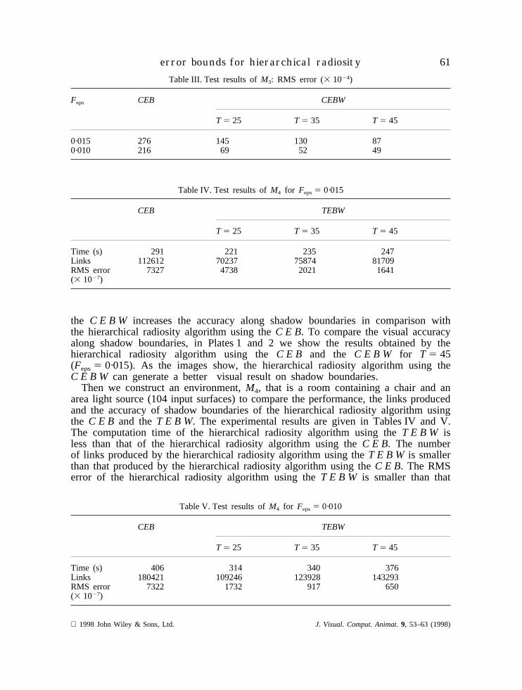
Next we construct a simple environment,M3, containing an area light source, anoccluder and a receiver in distinct parallel planes to compare the accuracy of shadowboundaries of the hierarchical radiosity algorithm using theC E B and theC E B W.Table III gives the results for two different user-specified error tolerances. As thetable shows, the RMS error obtained by the hierarchical radiosity algorithm usingthe C E B W is smaller than that obtained by the hierarchical radiosity algorithmusing theC E B. These results mean that the hierarchical radiosity algorithm using
Table II. Test results ofM2 (perpendicular case)
Feps Links Reduction rate(%)
CEB TEB
0·005 14416 6976 51·60·006 11656 5836 49·90·007 10516 5656 46·20·008 9046 4246 53·10·009 8296 3676 44·30·010 6976 3256 53·3
1998 John Wiley & Sons, Ltd. J. Visual. Comput. Animat.9, 53–63 (1998)
61error bounds for hierarchical radiosity
Table III. Test results ofM3: RMS error (3 1024)
Feps CEB CEBW
T 5 25 T 5 35 T 5 45
0·015 276 145 130 870·010 216 69 52 49
Table IV. Test results ofM4 for Feps5 0·015
CEB TEBW
T 5 25 T 5 35 T 5 45
Time (s) 291 221 235 247Links 112612 70237 75874 81709RMS error 7327 4738 2021 1641(3 1027)
the C E B W increases the accuracy along shadow boundaries in comparison withthe hierarchical radiosity algorithm using theC E B. To compare the visual accuracyalong shadow boundaries, in Plates 1 and 2 we show the results obtained by thehierarchical radiosity algorithm using theC E B and the C E B W for T 5 45(Feps5 0·015). As the images show, the hierarchical radiosity algorithm using theC E B W can generate a better visual result on shadow boundaries.
Then we construct an environment,M4, that is a room containing a chair and anarea light source (104 input surfaces) to compare the performance, the links producedand the accuracy of shadow boundaries of the hierarchical radiosity algorithm usingthe C E B and theT E B W. The experimental results are given in Tables IV and V.The computation time of the hierarchical radiosity algorithm using theT E B W isless than that of the hierarchical radiosity algorithm using theC E B. The numberof links produced by the hierarchical radiosity algorithm using theT E B W is smallerthan that produced by the hierarchical radiosity algorithm using theC E B. The RMSerror of the hierarchical radiosity algorithm using theT E B W is smaller than that
Table V. Test results ofM4 for Feps5 0·010
CEB TEBW
T 5 25 T 5 35 T 5 45
Time (s) 406 314 340 376Links 180421 109246 123928 143293RMS error 7322 1732 917 650(3 1027)
1998 John Wiley & Sons, Ltd. J. Visual. Comput. Animat.9, 53–63 (1998)
62 c.-c. chang and z.-c. shih
of the hierarchical radiosity algorithm using theC E B. These results mean that thehierarchical radiosity algorithm using theT E B Wnot only improves the performancebut also increases the accuracy of shadow boundaries in comparison with thehierarchical radiosity algorithm using theC E B. Hence we can get an efficienthierarchical radiosity algorithm capable of enhancing the accuracy along shadowboundaries. To compare the visual accuracy along shadow boundaries, in Plates 3and 4 we show the radiosity solutions obtained by the hierarchical radiosity algorithmusing theC E B and theT E B W for T 5 45 (Feps5 0·010). As the images show,the hierarchical radiosity algorithm using theT E B Wcan generate a better represen-tation along shadow boundaries.
Finally we apply the hierarchical radiosity algorithm using theT E B W to anenvironment containing 938 input surfaces. The user-specified error tolerance is setto 0·01 and the parameterT is set to 45. It takes about 162 min and creates 640,709links on the hierarchy for the radiosity solution. Plate 5 depicts the resulting image.
5. CONCLUSIONS AND FUTURE WORK
We derive a tighter error bound on form factors as a subdivision criterion for thehierarchical radiosity algorithm. Such an error bound can reduce many unnecessarylinks and improve the performance of the hierarchical radiosity algorithm to meet auser-specified error tolerance. Moreover, we propose a weighted error metric basedon the visibility for radiosity. Our method properly puts stress on aspects of shadowboundaries. Using the tighter error bound on the weighted error metric, we not onlyimprove the performance but also enhance the accuracy along shadow boundaries ofthe hierarchical radiosity algorithm.
Several problems need further research. First, we will make an in-depth study onderiving tighter error bounds on form factors. Next, the weighting function is basedon the visibility error for a point illuminated by an area light source. A more in-depth study should be made of the weighting function to construct better weightederror metrics for radiosity. Finally, the development of perceptually based errormetrics for image synthesis is necessary, since the complete simulation of a globalillumination model should consider the perception of observers.18 We will alsoconsider an image’s perception to derive more accurate error metrics for image syn-thesis.
Acknowledgements
This work was supported partially by the National Science Council, Republic ofChina, under grant NSC86–2745–E009–002. We would like to thank reviewers fortheir helpful suggestions.
REFERENCES
1. M. F. Cohen, D. P. Greenberg, D. S. Immel and P. J. Brock, ‘An efficient radiosity approach forrealistic image synthesis’,IEEE Computer Graphics and Applications, 6(3), 26–35 (1986).
2. P. Hanrahan, D. Salzman and L. Aupperle, ‘A rapid hierarchical radiosity algorithm’,ComputerGraphics, 25(4), 197–206 (1991).
3. A. A. Appel, ‘An efficient program for many-body simulation’,SIAM Journal on Scientific &Statistical Computing, 6(1), 85–103 (1985).
4. B. E. Smits, J. R. Arvo and D. H. Salesin, ‘An importance-driven radiosity algorithm’,ComputerGraphics, 26(2), 273–282 (1992).
1998 John Wiley & Sons, Ltd. J. Visual. Comput. Animat.9, 53–63 (1998)
63error bounds for hierarchical radiosity
5. B. Smits, J. Arvo and D. Greenberg, ‘A clustering algorithm for radiosity in complexity environ-ments’, Proceedings of ACM SIGGRAPH ’94, 1994, pp. 435–442.
6. J. Arvo, K. Torrance and B. Smits, ‘A framework for the analysis of error in global illuminationalgorithms’, Proceedings of ACM SIGGRAPH ’94, 1994, pp. 75–84.
7. D. Lischinski, B. Smits and D. P. Greenberg, ‘Bounds and error estimates for radiosity’,Proceedingsof ACM SIGGRAPH ’94, 1994, pp. 67–74.
8. M. Pellegrini, ‘Monte Carlo approximation of form factors with error bounded a priori’,Proceedingsof the Eleventh Annual ACM Symposium on Computational Geometry, 1995, pp. 287–296.
9. F. Sillion and G. Drettakis, ‘Feature-based control of visibility error: a multi-resolution clusteringalgorithm for global illumination’,Proceedings of ACM SIGGRAPH ’95, 1995, pp. 145–152.
10. P. R. Atherton, K. Weiler and D. P. Greenberg, ‘Polygon shadow generation’,Computer Graphics,12 (3), 275–281 (1978).
11. N. Chin and S. Feiner, ‘Near real-time shadow generation using BSP trees’,Computer Graphics,23(3), 99–106 (1989).
12. N. Chin and S. Feiner, ‘Fast object-precision shadow generation for area light sources using BSPtrees’, Proceedings of the 1992 Symposium on Interactive 3D Graphics, 1992, pp. 21–30.
13. F. C. Crow, ‘Shadow algorithms for computer graphics’,Computer Graphics, 11(2), 242–248 (1977).14. T. Nishita and E. Nakamae, ‘Continuous tone representation of three-dimensional objects taking
account of shadows and interreflection’,Computer Graphics, 19(3), 23–30 (1985).15. J. Stewart and S. Ghali, ‘Fast computation of shadow boundaries using spatial coherence and
backprojections’,Proceedings of ACM SIGGRAPH ’94, 1994, pp. 231–238.16. A. Watt and M. Watt,Advanced Animation and Rendering Techniques Theory and Practice,
Addison-Wesley, Reading, MA, 1992.17. C. C. Chang and Z. C. Shih, ‘Tighter error bounds on form factors for hierarchical radiosity’,
Proceedings of the Fourth Pacific Conference on Computer Graphics and Applications, PacificGraphics ’96, 1996, pp. 147–158.
18. M. F. Cohen and J. R. Wallace,Radiosity and Realistic Image Synthesis, Academic, New York, 1993.
1998 John Wiley & Sons, Ltd. J. Visual. Comput. Animat.9, 53–63 (1998)
![Introduction to Radiosity · EECS 487: Interactive Computer Graphics An[other] Intro to Radiosity(1/3) • The radiometric term radiosity means the rate at which energy leaves a surface,](https://img.pdfslide.us/doc/110x75/5fc3a89f74fa74617b240ea3/introduction-to-eecs-487-interactive-computer-graphics-another-intro-to-radiosity13.jpg)