Embed Size (px)
Citation preview
1
Measures of IlluminationThe Radiosity EquationForm FactorsRadiosity Algorithms
[Angel, Ch 13.4-13.5]
Measures of IlluminationThe Radiosity EquationForm FactorsRadiosity Algorithms
[Angel, Ch 13.4-13.5]
RadiosityRadiosity
Alternative NotesAlternative Notes
• SIGGRAPH 1993 Education Slide Set –Radiosity Overview, by Stephen Spencer
www.siggraph.org/education/materials/HyperGraph/radiosity/overview_1.htm
2
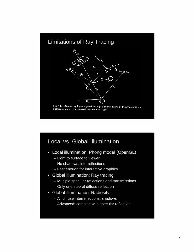
Limitations of Ray TracingLimitations of Ray Tracing
Local vs. Global IlluminationLocal vs. Global Illumination
• Local illumination: Phong model (OpenGL)– Light to surface to viewer– No shadows, interreflections– Fast enough for interactive graphics
• Global illumination: Ray tracing– Multiple specular reflections and transmissions– Only one step of diffuse reflection
• Global illumination: Radiosity– All diffuse interreflections; shadows– Advanced: combine with specular reflection
3
Image vs. Object SpaceImage vs. Object Space
• Image space: Ray tracing– Trace backwards from viewer– View-dependent calculation– Result: rasterized image (pixel by pixel)
• Object space: Radiosity– Assume only diffuse-diffuse interactions– View-independent calculation– Result: 3D model, color for each surface patch– Can render with OpenGL
Classical Radiosity MethodClassical Radiosity Method
• Divide surfaces into patches (elements)• Model light transfer between patches as system
of linear equations• Important assumptions:
– Reflection and emission are diffuse• Recall: diffuse reflection is equal in all directions
• So radiance is independent of direction
– No participating media (no fog)– No transmission (only opaque surfaces)– Radiosity is constant across each element– Solve for R, G, B separately
4
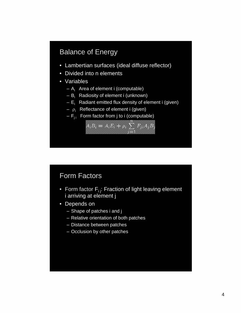
Balance of EnergyBalance of Energy
• Lambertian surfaces (ideal diffuse reflector)• Divided into n elements• Variables
– Ai Area of element i (computable)– Bi Radiosity of element i (unknown)– Ei Radiant emitted flux density of element i (given)
– Ui Reflectance of element i (given)– Fj i Form factor from j to i (computable)
Form FactorsForm Factors
• Form factor Fi j: Fraction of light leaving element i arriving at element j
• Depends on– Shape of patches i and j– Relative orientation of both patches– Distance between patches– Occlusion by other patches
5
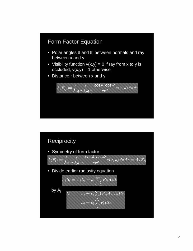
Form Factor EquationForm Factor Equation
• Polar angles T and T’ between normals and ray between x and y
• Visibility function v(x,y) = 0 if ray from x to y is occluded, v(x,y) = 1 otherwise
• Distance r between x and y
ReciprocityReciprocity
• Symmetry of form factor
• Divide earlier radiosity equation
by Ai
6
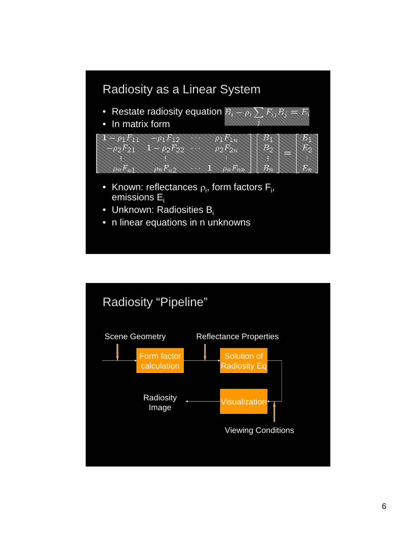
Radiosity as a Linear SystemRadiosity as a Linear System
• Restate radiosity equation• In matrix form
• Known: reflectances Ui, form factors Fi, emissions Ei
• Unknown: Radiosities Bi
• n linear equations in n unknowns
Radiosity “Pipeline”Radiosity “Pipeline”
Form factorcalculation
Solution ofRadiosity Eq
Visualization
Scene Geometry Reflectance Properties
Viewing Conditions
RadiosityImage
7
VisualizationVisualization
• Radiosity solution is viewer independent• Can exploit graphics hardware to obtain image• Convert color on patch to vertex color• Easy part of radiosity method
Computing Form FactorsComputing Form Factors
• Visibility critical• Two principal methods
– Hemicube: exploit z-buffer hardware– Ray casting (can be slow)– Both exhibit aliasing effects
• For inter-visible elements– Many special cases can be solved analytically– Avoid full numeric approximation of double integral
8
Hemicube AlgorithmHemicube Algorithm
• Render model onto a hemicube as seen from the center of a patch
• Store patch identifiers j instead of color• Use z-buffer to resolve visibility• Efficiently implementable in hardware• Examples of antialiasing [Chandran et al.]
[Chandran et al]
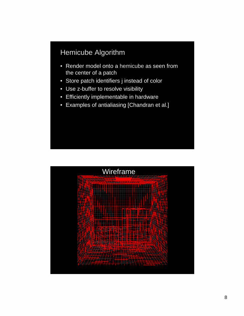
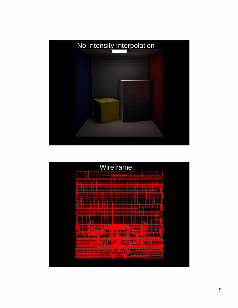
Wireframe
9
No Intensity Interpolation
Wireframe
10
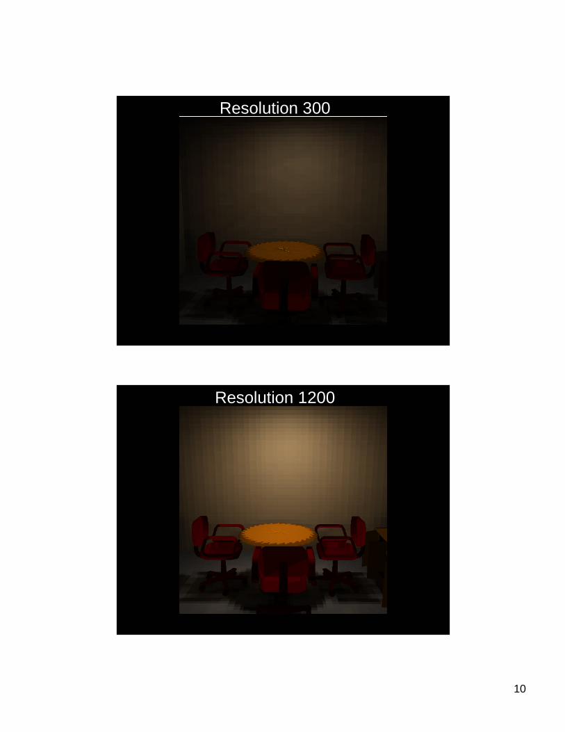
Resolution 300
Resolution 1200
11
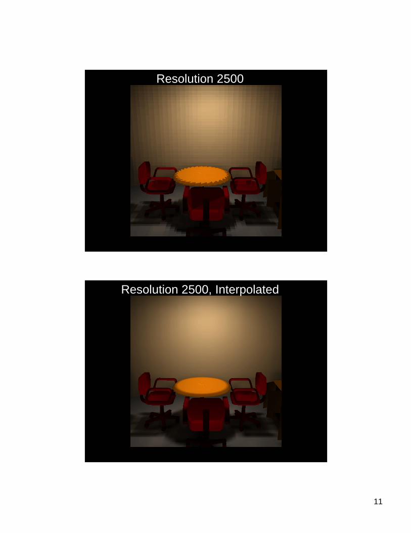
Resolution 2500
Resolution 2500, Interpolated
12
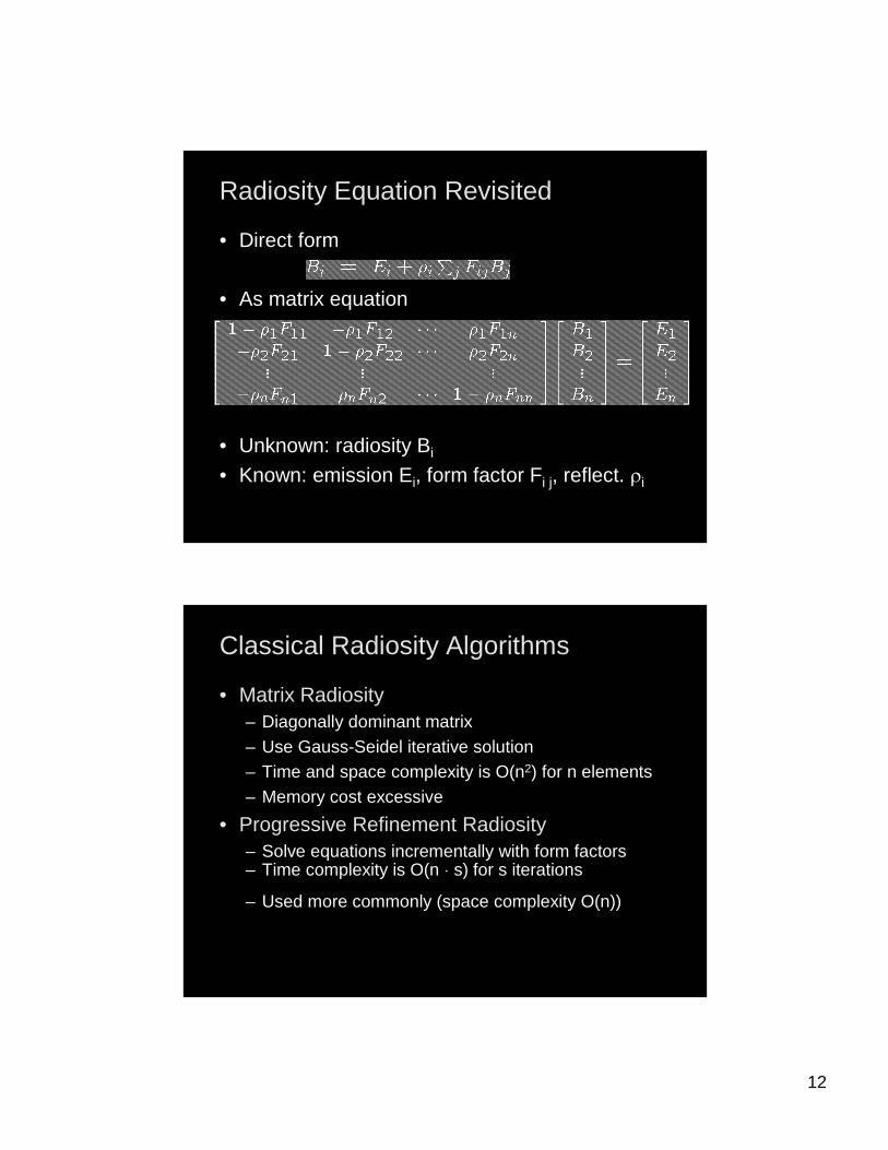
Radiosity Equation RevisitedRadiosity Equation Revisited
• Direct form
• As matrix equation
• Unknown: radiosity Bi
• Known: emission Ei, form factor Fi j, reflect. Ui
Classical Radiosity AlgorithmsClassical Radiosity Algorithms
• Matrix Radiosity– Diagonally dominant matrix– Use Gauss-Seidel iterative solution– Time and space complexity is O(n2) for n elements– Memory cost excessive
• Progressive Refinement Radiosity– Solve equations incrementally with form factors– Time complexity is O(n d s) for s iterations
– Used more commonly (space complexity O(n))
13
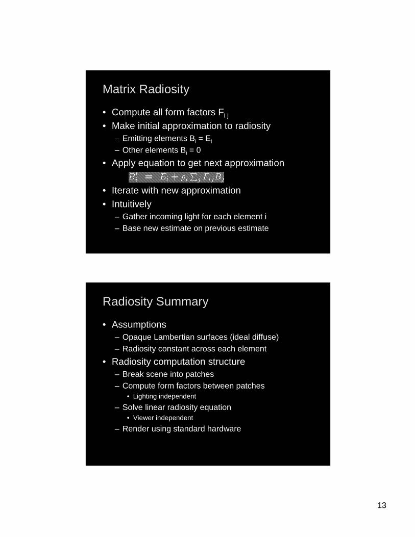
Matrix RadiosityMatrix Radiosity
• Compute all form factors Fi j
• Make initial approximation to radiosity– Emitting elements Bi = Ei
– Other elements Bi = 0
• Apply equation to get next approximation
• Iterate with new approximation• Intuitively
– Gather incoming light for each element i– Base new estimate on previous estimate
Radiosity SummaryRadiosity Summary
• Assumptions– Opaque Lambertian surfaces (ideal diffuse)– Radiosity constant across each element
• Radiosity computation structure– Break scene into patches– Compute form factors between patches
• Lighting independent
– Solve linear radiosity equation• Viewer independent
– Render using standard hardware
14
Lecture SummaryLecture Summary
• The Radiosity Equation• Form Factors• Radiosity Algorithms
15
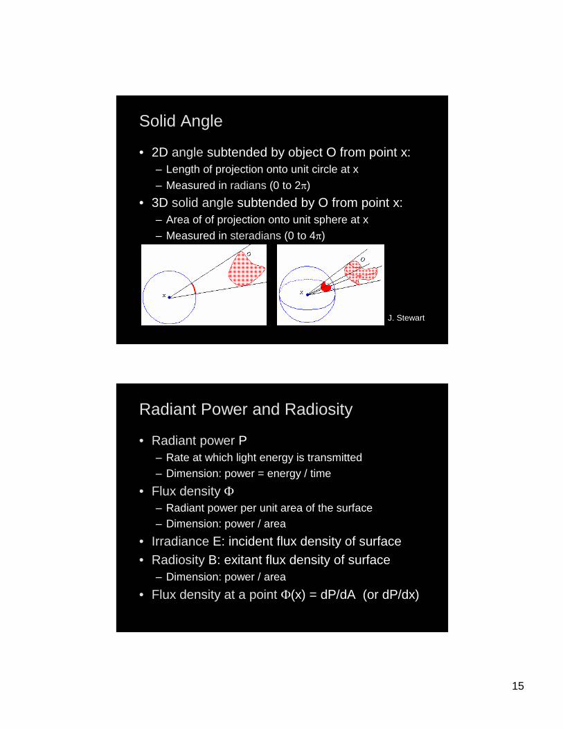
Solid AngleSolid Angle
• 2D angle subtended by object O from point x:– Length of projection onto unit circle at x
– Measured in radians (0 to 2S)
• 3D solid angle subtended by O from point x:– Area of of projection onto unit sphere at x
– Measured in steradians (0 to 4S)
J. Stewart
Radiant Power and RadiosityRadiant Power and Radiosity
• Radiant power P– Rate at which light energy is transmitted– Dimension: power = energy / time
• Flux density )– Radiant power per unit area of the surface– Dimension: power / area
• Irradiance E: incident flux density of surface• Radiosity B: exitant flux density of surface
– Dimension: power / area
• Flux density at a point )(x) = dP/dA (or dP/dx)

16
Power at Point in a DirectionPower at Point in a Direction
• Radiant intensity I– Power radiated per unit solid angle by point source– Dimension: power / solid angle
• Radiant intensity in direction Z– I(Z) = dP/dZ
• Radiance L(x, Z)– Flux density at point x in direction Z– Dimension: power / (area e solid angle)
RadianceRadiance
• Measured across surface in direction Z
• For angle T between Z and normal n
J. Stewart ‘98
17
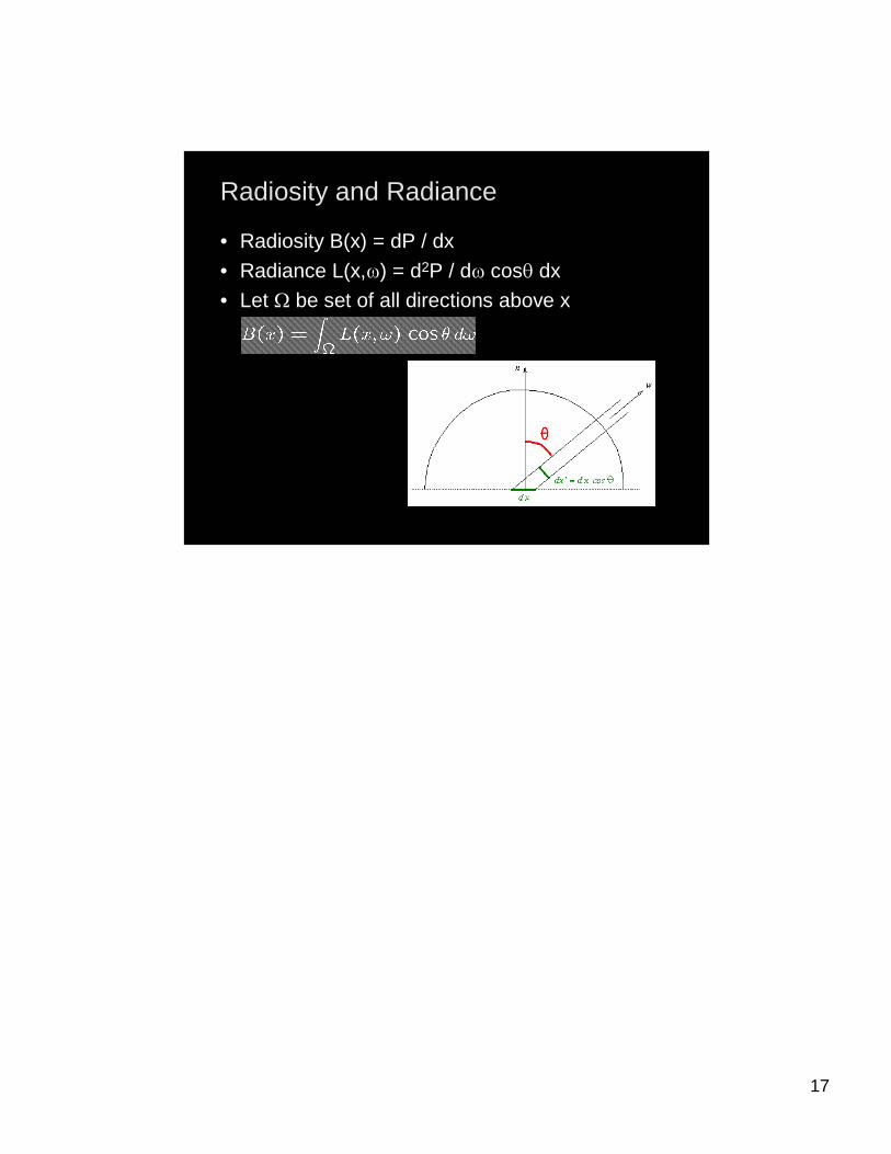
Radiosity and RadianceRadiosity and Radiance
• Radiosity B(x) = dP / dx
• Radiance L(x,Z) = d2P / dZ cosT dx• Let : be set of all directions above x