Embed Size (px)
Citation preview
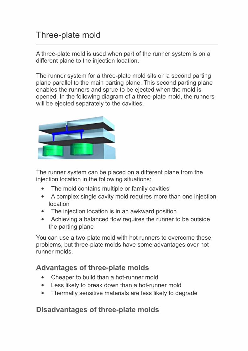
Three-plate mold
A three-plate mold is used when part of the runner system is on a different plane to the injection location.
The runner system for a three-plate mold sits on a second parting plane parallel to the main parting plane. This second parting plane enables the runners and sprue to be ejected when the mold is opened. In the following diagram of a three-plate mold, the runners will be ejected separately to the cavities.
The runner system can be placed on a different plane from the injection location in the following situations:
The mold contains multiple or family cavities A complex single cavity mold requires more than one injection
location The injection location is in an awkward position Achieving a balanced flow requires the runner to be outside
the parting plane
You can use a two-plate mold with hot runners to overcome these problems, but three-plate molds have some advantages over hot runner molds.
Advantages of three-plate molds Cheaper to build than a hot-runner mold Less likely to break down than a hot-runner mold Thermally sensitive materials are less likely to degrade
Disadvantages of three-plate molds

Higher cycle time due to ejection of the runner system More material is wasted Greater injection pressure is required to fill the mold
Parent topic: Mold types

Tool Design Mould Cooling System and Design Consideration...
Mold cooling system overview
Importance of cooling system design:-Mold cooling accounts for more than two-thirds of the total cycle time in the production of injection molded thermoplastic parts. Figure 1 illustrates this point. An efficient cooling circuit design reduces the cooling time, which, in turn, increases overall productivity. Moreover, uniform cooling improves part quality by reducing residual stresses and maintaining dimensional accuracy and stability (see Figure 2).

FIGURE 1. Mold cooling accounts for more than two-thirds of the total cycle time.
FIGURE 2. Proper and efficient cooling improves part quality and productivity
Mold cooling system components
A mold cooling system typically consists of the following items:- Temperature controlling unit- Pump- Supply manifold- Hoses- Cooling channels in the mold- Collection manifold
The mold itself can be considered as a heat exchanger, with heat from the hot polymer melt taken away by the circulating coolant.
Figures 3 and 4 illustrate the components of a typical cooling system.

FIGURE 3. A typical cooling system for an injection molding machine.
FIGURE 4. A cooling channel assembly attached to the mold plates.
Cooling-channel configuration
Types of cooling channels

Cooling-channel configurations can be serial or parallel. Both configurations are illustrated in Figure 1 below.
FIGURE 1. Cooling-channel configurations
Parallel cooling channels:-
Parallel cooling channels are drilled straight through from a supply manifold to a collection manifold. Due to the flow characteristics of the parallel design, the flow rate along various cooling channelsmay be different, depending on the flow resistance of each individual cooling channel. These varying flow rates in turn cause the heat transfer efficiency of the cooling channels to vary from one to another. As a result, cooling of the mold may not be uniform with a parallel cooling-channel configuration.
Typically, the cavity and core sides of the mold each have their own system of parallel cooling channels. The number of cooling channels per system varies with the size and complexity of the mold.
Serial cooling channels
Cooling channels connected in a single loop from the coolant inlet to its outlet are called serial cooling channels. This type of cooling-channel configuration is the most commonly recommended and used. By design, if the cooling channels are uniform in size, the coolant can maintain its (preferably) turbulent flow rate through its entire length. Turbulent flow enables heat to be transferred more effectively. Heat transfer of coolant flow discusses this more thoroughly. However, you should take care to minimize the temperature rise of the coolant, since the coolant will collect all the heat along the entire cooling-channel path. In general, the temperature difference of the coolant at the inlet and the exit should be within 5ºC for general-purpose molds and 3ºC for precision molds. For

large molds, more than one serial cooling channel may be required to assure Cooling-channel Configuration uniform coolant temperature and thus uniform mold cooling.
What do they do?Baffles and bubblers are sections of cooling lines that divert the coolant flow into areas that would normally lack cooling. Cooling channels are typically drilled through the mold cavity and core. The mold, however, may consist of areas too far away to accommodate regular cooling channels. Alternate methods for cooling these areas uniformly with the rest of the part involve the use of Baffles, Bubblers, or Thermal pins, as shown below.
FIGURE 1. Baffle, bubbler, and thermal pin
Baffles
A baffle is actually a cooling channel drilled perpendicular to a main cooling line, with a blade that separates one cooling passage into two semi-circular channels. The coolant flows in one side of the blade from the main cooling line, turns around the tip to the other side of the baffle, then flows back to the main cooling line.
This method provides maximum cross sections for the coolant, but it is difficult to mount the divider exactly in the center. The cooling effect and with it the temperature distribution on one side of the core may differ from that on the other side. This disadvantage of an otherwise economical solution, as far as manufacturing is concerned, can be eliminated if the metal sheet forming the baffleis twisted. For example, the helix baffle, as shown in Figure 2 below, conveys the coolant to the tip and back in the form of a helix. It is useful for diameters of 12 to 50 mm, and makes for a very homogeneous temperature distribution. Another logical development of baffles are single- or double-flight spiral cores, as shown inFigure 2 below.

FIGURE 2. (Left) Helix baffle. (Right) Spiral baffle.
Bubblers
A bubbler is similar to a baffle except that the blade is replaced with a small tube. The coolant flows into the bottom of the tube and “bubbles” out of the top, as doesa fountain. The coolant then flows down around the outside of the tube to continueits flow through the cooling channels.
The most effective cooling of slender cores is achieved with bubblers. The diameter of both must be adjusted in such a way that the flow resistance in both cross sections is equal. The condition for this is:-
Inner Diameter / Outer Diameter = 0.707
Bubblers are commercially available and are usually screwed into the core, as shown in Figure 3 below. Up to a diameter of 4 mm, the tubing should be beveled at the end to enlarge the cross section of the outlet; this technique is illustrated in Figure 3. Bubblers can be used not only for core cooling, but are also for cooling flat mold sections, which can’t be equipped with drilled or milled channels.

FIGURE 3. (Left) Bubblers screwed into core. (Right) Bubbler beveled to enlarge outlet
NOTE: Because both baffles and bubblers have narrowed flow areas, the flow resistance increases. Therefore, care should be taken in designing the size of these devices. The flow and heat transfer behavior for both baffles and bubblers can be readily modeled and analyzed by C-MOLD Cooling analysis.
Thermal pins
A thermal pin is an alternative to baffles and bubblers. It is a sealed cylinder filled with a fluid. The fluid vaporizes as it draws heat from the tool steel and condenses as it releases the heat to the coolant, as shown in Figure 4. The heat transfer efficiency of a thermal pin is almost ten times as great as a copper tube. For good heat conduction, avoid an air gap between the thermal pin and the mold, or fill it with a highly conductive sealant.

FIGURE 4. Thermal pin heat transfer efficiency
Cooling slender coresIf the diameter or width is very small (less than 3 mm), only air cooling is feasible. Air is blown at the cores from the outside during mold opening or flows through a central hole from inside, as shown in Figure 5. This procedure, of course, does not permit maintaining an exact mold temperature.
FIGURE 5. Air cooling of a slender coreBetter cooling of slender cores (those measuring less than 5 mm) is accomplished by using inserts made of materials with high thermal conductivity, such as copper or beryllium-copper materials. This technique is illustrated in Figure 6 below. Such inserts are press-fitted into the core and extend with their base, which has a cross section as large as is feasible, into a cooling channel.
FIGURE 6. Using high thermal conductivity material to cool a slender core
Cooling large cores
For large core diameters (40 mm and larger), a positive transport of coolant must be ensured. This can be done with inserts in which the coolant reaches the tip of the core through a central bore and is led through a spiral to its circumference, andbetween core and insert helically to the outlet, as shown in Figure 7. This design weakens the core significantly.

FIGURE 7. Use of helical baffle to cool large core
Cooling cylinder cores
Cooling of cylinder cores and other round parts should be done with a double helix, as shown below. The coolant flows to the core tip in one helix and returns in another helix. For design reasons, the wall thickness of the core should be at least 3 mm in this case.
FIGURE 8. Double helix with center bubbler
Cooling time
Theoretically, cooling time is proportional to the square of the heaviest part wall thickness or the power of 1.6 for the largest runner diameter. That is:

where the thermal diffusivity of polymer melt is defined as
In other words, doubling the wall thickness quadruples the cooling time.
Reynolds number and coolant flow
Whether or not the coolant flow is turbulent can be determined by the Reynolds number (Re), as listed in Table 1. The Reynolds number is defined as:
where ρ is the density of the coolant, U is the averaged velocity of the coolant, d is the diameter of the cooling channel, and η is the dynamic viscosity of the coolant.
TABLE 1. Coolant flow types and correspondingReynolds number ranges

Mold
Mold or die are the common terms used to describe the tooling used to produce plastic parts in molding.
Traditionally, molds have been expensive to manufacture. They were usually only used in mass production where thousands of parts were being produced. Molds are typically constructed from hardened steel, pre-hardened steel, aluminium, and/or beryllium-copper alloy. The choice of material to build a mold from is primarily one of economics, steel molds generally cost more to construct, but their longer lifespan will offset the higher initial cost over a higher number of parts made before wearing out. Pre-hardened steel molds areless wear resistant and are used for lower volume requirements or larger components. The steel hardness is typically 38-45 on the Rockwell-C scale. Hardened steel molds are heat treated after machining. These are by far the superior in terms of wear resistance and lifespan. Typical hardness ranges between 50 and 60 Rockwell-C (HRC). Aluminium molds can cost substantially less, and when designed and machined with modern computerized equipment, can be economical for molding tens or even hundreds of thousands of parts. Beryllium copper is used in areas of the mold which require fast heat removal or areas that see the most shear heat generated. The molds can be manufactured by either CNC machining or by using Electrical Discharge Machining processes
Injection molding die with side pulls
"A" side of die for 25%glass-filled acetal with
2 side pulls.
Close up ofremovable insert in
"A" side.
"B" side of die withside pull actuators.
Insert removedfrom die.

Mold Design
Molds separate into two sides at a parting line, the A side, and the B side, to permit the part to be extracted. Plastic resin enters the mold through asprue in the A plate, branches out between the two sides through channels called runners, and enters each part cavity through one or more specializedgates. Inside each cavity, the resin flows around protrusions (called cores) and conforms to the cavity geometry to form the desired part. This is similar to someone squeezing clay between their hands so that when it is removed, it matches the shape of the hollow of their cupped hands.
The amount of resin required to fill the sprue, runner and cavities of a mold is a shot. When a core shuts off against an opposing mold cavity or core, a hole results in the part. Air in the cavities when the mold closes escapes through very slight gaps between the plates and pins, into shallow plenums called vents.To permit removal of the part, its features must not overhang one another in the direction that the mold opens, unless parts of the mold are designed to move from between such overhangs when the mold opens (utilizing components called Lifters).
Sides of the part that appear parallel with the direction of draw (the direction in which the core and cavity separate from each other) are typically angled slightly with (draft) to ease release of the part from the mold, and examination of most plastic household objects will reveal this. Parts with bucket-like features tend to shrink onto the cores that form them while cooling,and cling to those cores when the cavity is pulled away. The mold is usually designed so that the molded part reliably remains on the ejector (B) side of the mold when it opens, and draws the runner and the sprue out of the (A) side along with the parts. The part then falls freely when ejected from the (B) side. Tunnel gates tunnel sharply below the parting surface of the B side at the tip of each runner so that the gate is sheared off of the part when both are ejected.
Ejector pins are the most popular method for removing the part from the B side core(s), but air ejection, and stripper plates can also be used depending onthe application. Most ejection plates are found on the moving half of the tool, but they can be placed on the fixed half if spring loaded. For thermoplastics, coolant, usually water with corrosion inhibitors, circulates through passageways bored through the main plates on both sides of the mold to enabletemperature control and rapid part solidification.
To ease maintenance and venting, cavities and cores are divided into pieces, called inserts, and sub-assemblies, also called inserts, blocks, or chase blocks.

By substituting interchangeable inserts, one mold may make several variations of the same part.
More complex parts are formed using more complex molds. These may have sections called slides, that move into a cavity perpendicular to the draw direction, to form overhanging part features. Slides are then withdrawn to allow the part to be released when the mold opens. Slides are typically guided and retained between rails called gibs, and are moved when the mold opens and closes by angled rods called horn pins and locked in place by locking blocks, both of which move cross the mold from the opposite side.
Some molds allow previously molded parts to be reinserted to allow a new plastic layer to form around the first part. This is often referred to asovermolding. This system can allow for production of one-piece tires and wheels.
2-shot or multi-shot molds are designed to "overmold" within a single molding cycle and must be processed on specialized injection molding machines with two or more injection units. This can be achieved by having pairs of identical cores and pairs of different cavities within the mold. After injection of the first material, the component is rotated on the core from the one cavity to another. The second cavity differs from the first in that the detail for the second material is included. The second material is then injected into the additional cavity detail before the completed part is ejected from the mold. Common applications include "soft-grip" toothbrushes and freelander grab handles.
The core and cavity, along with injection and cooling hoses form the mold tool. While large tools are very heavy weighing hundreds and sometimes thousands of pounds, with the aid of a forklift or overhead crane, they can be hoisted into molding machines for production and removed when molding is complete or the tool needs repairing.
A mold can produce several copies of the same parts in a single "shot". The number of "impressions" in the mold of that part is often incorrectly referred to as cavitation. A tool with one impression will often be called a single cavity (impression) tool. A mold with 2 or more cavities of the same parts will likely be referred to as multiple cavity tooling. Some extremely high production volume molds (like those for bottle caps) can have over 128 cavities.
In some cases multiple cavity tooling will mold a series of different parts in the same tool. Some toolmakers call these molds family molds as all the parts.

Effects on the material properties
The mechanical properties of a part are usually little effected. Some parts can have internal stresses in them. This is one of the reasons why it's good to have uniform wall thickness when molding. One of the physical property changes is shrinkage. A permanent chemical property change is the material thermoset, which can't be remelted to be injected again.
The effects on work material properties is best illustrated by the table below from Manufacturing Processes Reference Guide:
Work Material Properties Effects of Injection Molding
Mechanical Plastic components may develop internal stress
Physical Permanent shrinkage at elevated temperatures
Chemical Thermoset materials cannot be remelted
Tool Materials
Tool steel or beryllium-copper are often used. Mild steel, aluminum, nickel or epoxy are only suitable for prototype or very short production runs.
Geometrical Possibilities
The most commonly used plastic molding process, injection molding, is used tocreate a large variety of products with different shapes and sizes. Most importantly, they can create products with complex geometry that many other processes cannot. There are a few precautions when designing something that will be made using this process to reduce the risk of weak spots. First, streamline your product or keep the thickness relatively uniform. Second, try and keep your product between 2 to 20 inches.
The size of a part will depend on a number of factors (material, wall thickness, shape,process ect). The initial raw material required may be measured in the form of granules, pellets or powders. Here are some ranges of the sizes.
Method Raw MaterialsMaximum
SizeMinimum
Size
Injection Molding(thermo-plastic)
Granules, Pellets,Powders
700 oz. Less than 1 oz.
Injection Molding(thermo-setting)
Granules, Pellets,Powders
200 oz. Less Than 1 oz.
Machining
Molds are built through two main methods: standard machining and EDM. Standard Machining, in its conventional form, has historically been the methodof building injection molds. With technological development, CNC machining became the predominant means of making more complex molds with more accurate mold details in less time than traditional methods.
The electrical discharge machining (EDM) or spark erosion process has become widely used in mold making. As well as allowing the formation of shapes which are difficult to machine, the process allows pre-hardened molds to be shaped so that no heat treatment is required. Changes to a hardened mold by conventional drilling and milling normally require annealing to soften the steel, followed by heat treatment to harden it again. EDM is a simple process in which a shaped electrode, usually made of copper or graphite, is very slowly lowered onto the mold surface (over a period of many hours), which is immersed in paraffin oil. A voltage applied between tool and mold causes spark erosion of the mold surface in the inverse shape of the electrode.
Cost
The cost of manufacturing molds depends on a very large set of factors ranging from number of cavities, size of the parts (and therefore the mold), complexity of the pieces, expected tool longevity, surface finishes and many others. The initial cost is great, however the piece part cost is low, so with greater quantities the overall price decreases.
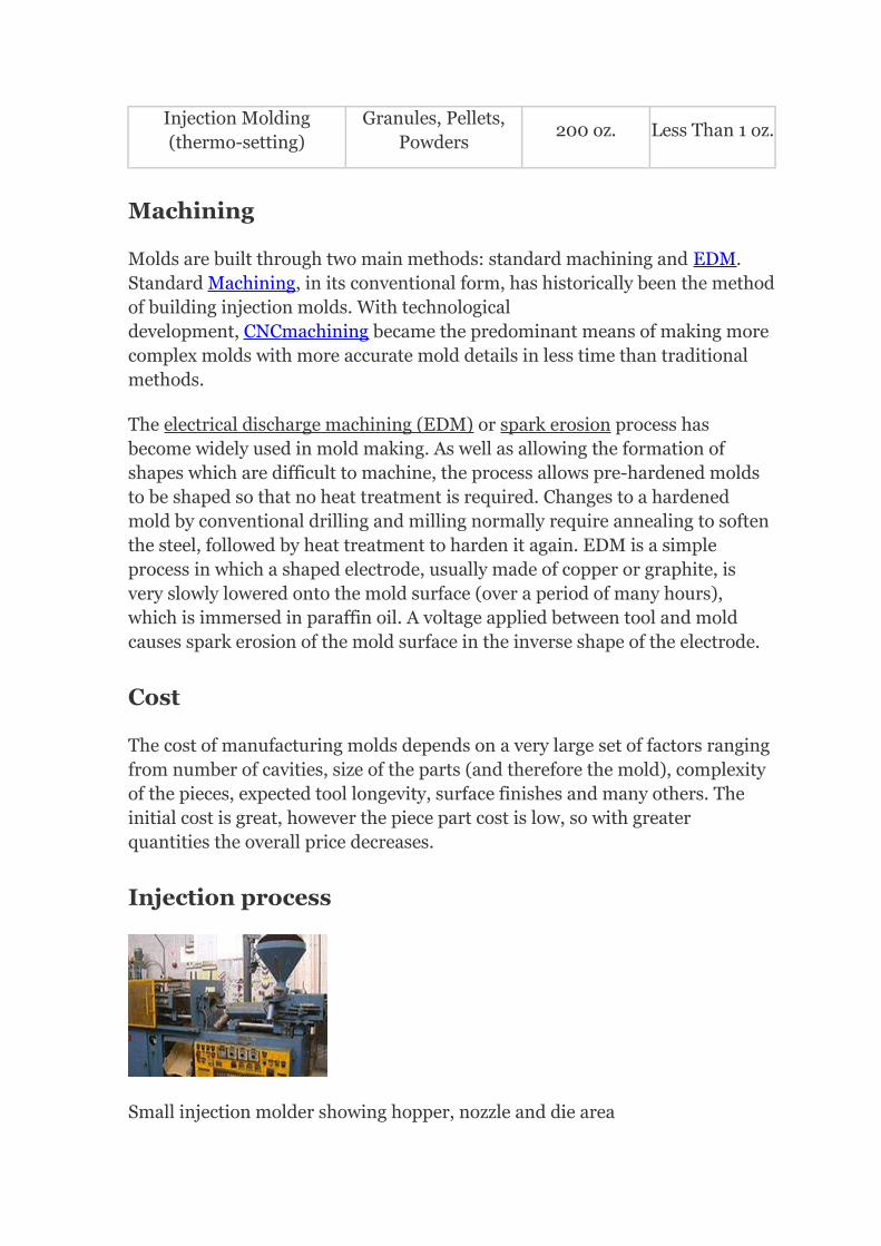
Injection process
Small injection molder showing hopper, nozzle and die area

For detailed explanation refer below to "Injection Molding Cycle".
With Injection Molding, granular plastic is fed by gravity from a hopper into a heated barrel. As the granules are slowly moved forward by a screw-type plunger, the plastic is forced into a heated chamber, where it is melted. As the plunger advances, the melted plastic is forced through a nozzle that rests against the mold, allowing it to enter the mold cavity through a gate and runner system. The mold remains cold so the plastic solidifies almost as soon as the mold is filled.
Injection molding cycle
For the injection molding cycle to begin, four criteria must be met: mold open, ejector pins retracted, shot built, and carriage forward. When these criteria are met, the cycle begins with the mold closing. This is typically done as fast as possible with a slow down near the end of travel. Mold safety is low speed and low pressure mold closing. It usually begins just before the leader pins of the mold and must be set properly to prevent accidental mold damage. When the mold halves touch clamp tonnage is built. Next, molten plastic material is injected into the mold. The material travels into the mold via the sprue bushing, then the runner system delivers the material to the gate. The gate directs the material into the mold cavity to form the desired part. This injectionusually occurs under velocity control.
When the part is nearly full, injection control is switched from velocity control to pressure control. This is referred to as the pack/hold phase of the cycle. Pressure must be maintained on the material until the gate solidifies to preventmaterial from flowing back out of the cavity. Cooling time is dependent primarily on the wall thickness of the part but also depends on the material being molded. Production molding usually requires faster cooling. Water is often channeled throughout the dies to produce faster cooling times. During the cooling portion of the cycle after the gate has solidified, plastication takes place.
Plastication is the process of melting material and preparing the next shot. The material begins in the hopper and enters the barrel through the feed throat. The feed throat must be cooled to prevent plastic pellets from fusing together from the barrel heat. The barrel contains a screw that primarily uses shear to melt the pellets and consists of three sections. The first section is the feed section which conveys the pellets forward and allows barrel heat to soften the pellets. The flight depth is uniform and deepest in this section. The next sectionis the transition section and is responsible for melting the material through shear. The flight depth continuously decreases in this section, compressing the

material. The final section is the metering section which features a shallow flight depth, improves the melt quality and color dispersion. At the front of the screw is the non-return valve which allows the screw to act as both an extruder and a plunger. When the screw is moving backwards to build a shot, the non-return assembly allows material to flow in front of the screw creating a melt pool or shot. During injection, the non-return assembly prevents the shot from flowing back into the screw sections.
Once the shot has been built and the cooling time has timed out, the mold opens. Mold opening must occur slow-fast-slow. The mold must be opened slowly to release the vacuum that is caused by the injection molding process and prevent the part from staying on the stationary mold half. This is undesirable because the ejection system is on the moving mold half. Then the mold is opened as far as needed, if robots are not being used, the mold only hasto open far enough for the part to be removed. A slowdown near the end of travel must be utilized to compensate for the momentum of the mold. Without slowing down the machine cannot maintain accurate positions and may slam to a stop damaging the machine. Once the mold is open, the ejector pins are moved forward, ejecting the part. When the ejector pins retract, all criteria for a molding cycle have been met and the next cycle can begin.
The basic injection cycle is as follows: Mold close – injection carriage forward – inject plastic – metering – carriage retract – mold open – eject part(s) Some machines are run by electric motors instead of hydraulics or a combination of both. The water-cooling channels that assist in cooling the mold and the heated plastic solidifies into the part. Improper cooling can resultin distorted molding. The cycle is completed when the mold opens and the partis ejected with the assistance of ejector pins within the mold.
The resin, or raw material for injection molding, is most commonly supplied in pellet or granule form. Resin pellets are poured into the feed hopper, a large open bottomed container, which is attached to the back end of a cylindrical, horizontal barrel. A screw within this barrel is rotated by a motor, feeding pellets up the screw's grooves. The depth of the screw flights decreases toward the end of the screw nearest the mold, compressing the heated plastic. As the screw rotates, the pellets are moved forward in the screw and they undergo extreme pressure and friction which generates most of the heat needed to melt the pellets. Electric heater bands attached to the outside of the barrel assist in the heating and temperature control during the melting process.
The channels through which the plastic flows toward the chamber will alsosolidify, forming an attached frame. This frame is composed of the sprue, which is the main channel from the reservoir of molten resin, parallel with the

direction of draw, and runners, which are perpendicular to the direction of draw, and are used to convey molten resin to the gate(s), or point(s) of injection. The sprue and runner system can be cut or twisted off and recycled, sometimes being granulated next to the mold machine. Some molds are designed so that the part is automatically stripped through action of the mold.
Time Function
The time it takes to make a product using injection molding can be calculatedby adding:
Twice the Mold Open/Close Time (2M)+
Injection Time (T)+
Cooling Time (C)+
Ejection Time (E)
Where T is found by dividing:Mold Size (S) / Flow Rate (F)
Total time = 2M + T + C + ET = V/R
V = Mold cavity size (in3)R = Material flow rate (in3/min)
http://upload.wikimedia.org/wikipedia/commons/9/9e/Time_Calculation.jpg
Molding trial
When filling a new or unfamiliar mold for the first time, where shot size for that mold is unknown, a technician/tool setter usually starts with a small shot weight and fills gradually until the mold is 95 to 99% full. Once this is achieved a small amount of holding pressure will be applied and holding time increased until gate freeze off has occurred, then holding pressure is increased until the parts are free of sinks and part weight has been achieved. Once the parts are good enough and have passed any specific criteria, a setting sheet is produced for people to follow in the future.

Process optimization is done using the following methods. Injection speeds are usually determined by performing viscosity curves. Process windows are performed varying the melt temperatures and holding pressures. Pressure dropstudies are done to check if the machine has enough pressure to move the screw at the set rate. Gate seal or gate freeze studies are done to optimize the holding time. A cooling time study is done to optimize the cooling time.
Molding defects
Injection molding is a complex technology with possible production problems. They can either be caused by defects in the molds or more often by part processing (molding)
MoldingDefects
Alternative name
Descriptions Causes
Blister BlisteringRaised or layered zone on
surface of the part
Tool or material is toohot, often caused by alack of cooling around
the tool or a faultyheater
Burn marksAir Burn/Gas Burn
Black or brown burnt areason the part located at
furthest points from gate
Tool lacks venting,injection speed is too
high
Colorstreaks(US)
Colourstreaks (UK)
Localized change ofcolor/colour
Masterbatch isn'tmixing properly, or the
material has run outand it's starting to comethrough as natural only
Delamination
Thin mica like layersformed in part wall
Contamination of thematerial e.g.PP mixed
with ABS, verydangerous if the part isbeing used for a safetycritical application asthe material has verylittle strength whendelaminated as the
materials cannot bond
Flash Burrs Excess material in thin layer Tool damage, too much

exceeding normal partgeometry
injectionspeed/material
injected, clamping forcetoo low. Can also becaused by dirt and
contaminants aroundtooling surfaces.
Embeddedcontaminates
Embeddedparticulates
Foreign particle (burntmaterial or other)
embedded in the part
Particles on the toolsurface, contaminated
material or foreigndebris in the barrel, ortoo much shear heatburning the material
prior to injection
Flow marks Flow linesDirectionally "off tone"wavy lines or patterns
Injection speeds tooslow (the plastic has
cooled down too muchduring injection,
injection speeds mustbe set as fast as you can
get away with at alltimes)
Jetting Deformed part by turbulent
flow of material
Poor tool design, gateposition or runner.
Injection speed set toohigh.
Polymerdegradation
polymer breakdown
fromhydrolysis,oxidation etc
Excess water in thegranules, excessive
temperatures in barrel
Sink marks Localized depression (In
thicker zones)
Holding time/pressuretoo low, cooling time
too short, withsprueless hot runnersthis can also be caused
by the gate temperaturebeing set too high
Short shot Non-fill /Short mold
Partial part Lack of material,injection speed or

pressure too low
Splay marksSplash mark
/ Silverstreaks
Circular pattern aroundgate caused by hot gas
Moisture in thematerial, usually
when hygroscopic resins are dried improperly
Stringiness StringingString like remain fromprevious shot transfer in
new shot
Nozzle temperature toohigh. Gate hasn't frozen
off
Voids Empty space within part
(Air pocket)
Lack of holdingpressure (holding
pressure is used to packout the part during the
holding time). Alsomold may be out of
registration (when thetwo halves don't centerproperly and part walls
are not the samethickness)
Weld lineKnit line /Meld line
Discolored line where twoflow fronts meet
Mold/materialtemperatures set too
low (the material is coldwhen they meet, so they
don't bond)
Warping Twisting Distorted part
Cooling is too short,material is too hot, lackof cooling around thetool, incorrect water
temperatures (the partsbow inwards towards
the hot side of the tool)
Tolerances and Surfaces
Injection molding typically is capable of tolerances equivalent to an IT Grade ofabout 9–14. The possible tolerance of a thermoplastic or a thermoset is +/-0.008 to +/-0.002 inches. Surface finishes of two to four microinches or better are can be obtained. Rough or pebbled surfaces are also possible


![Θεωρία De Broglie [1923] · Η εξίσωση δεν είναι Σχετικιστική [Dirac] και το Η/Μ πεδίο είναι συνεχές (V) ενώ το Η/Μ](https://img.pdfslide.us/doc/110x75/5f4a959a9a0d826cee40bda5/-de-broglie-1923-ff-f.jpg)