Embed Size (px)
Citation preview
911390
Three-Dimensional Tracking with Misalignment Between Display and Control Axes
Stephen R. Ellis NASA Ames Research Ctr.
Moffett Field, CA School of Optometry and School of Engrg.
Abstract
University of California, Berkeley Berkeley, CA
Two experiments were conducted examining . three-dimensional pursuit tracking when operators of
teleoperation simulations are faced with misalignment between the display and control frames of reference.
Targets on the experimental displays moved irregularly in three dimensions and were tracked by subjects using either two 2-axis joysticks and a panelmounted perspective display or, in a separate experiment, a hand-mounted, 6 degree-of-freedom electromagnetic sensor and a head-mounted, virtual image, stereoscopic display.
. Analysis of the components of the tracking er-I ror::; in the perspective display experiment showed that I components of the error due to misalignment of the
I, perspective projection may be linearly separated from
those associated with the mismatch between display , and control coordinate systems.
We observed evidence from both experimental I conditions that the tracking improved with several
hours practice. Differences between our results and previous results may be due to dynamical differences in the characteristics of the target and cursor and differences in tracking paradigm. The cause of the increased tracking error may be the users' processing time lags introduced by attempts to correct for the display-control misalignments.
Introduction
The design task for telemanipulation displays is complicated by the fact that the three-dimensional data they depict may entail viewing from nonoptimal directions. The viewing projection is described by a number of parameters each of which can substantially
Mitchell Tyler, Won S. Kim, and Lawrence Stark School of Optometry and School of Engrg.
985
University of California, Berkeley Berkeley, CA
alter the appearance of the resulting image. Since the purpose of the display is the accurate depiction of spatial information and successful manipulation of objects, designers must first understand the effects of these display parameters on operator perception and control in the work space. Studies of the effects of some of the major prOjection parameters, i.e. viewing direction and field of view angle (FOV), on the perception of eXQcentric direction have been reported recently (1) (2) (3) (4). Other studies of manipulation and control of telemanipulated objects also have been reported over the past 20 years (5) (6) (7) (8)(9) (1Q) (11).
The present experiments and analYSis extend these investigations with studies of pursuit tracking of virtual objects moving irregularly in three dimensions and focus on the spatial components of the tracking error.
In these experiments the FOV angle is defined as the visual angle subtended by the viewport as seen from the geometric center of the projection. The azimuth and elevation of the viewing vector are defined by angles between the world coordinate system and an extension of the viewing vector to a reference point. In general, the FOV was correctly matched by placing the subject's eye at the correct station point while misalignments between display and control axes were introduced by rotating the azimuth of the viewing direction. These misalignments were used to produce a decrement in human tracking performance in a manner similar to that of studies by Bernotat (8). The , resulting pattern of degraded performance, which has been found to be a function of the amount of misalignment, provides a basis for examining Bernotat's claim that subjects cannot adapt to the misalignment. In addition, errors in tracking will provide data to assess the suitability of integrated measurement of tracking error versus analysis of the components of the error.
~1345A
Colli9l'ophic , I)~play
4K x16 bit Memory
Joysticks
LSI-I1/23 Computer
If<--~ ~ro"el I/O
Serial 110
1:==:1 12 - bit AID CorNerter
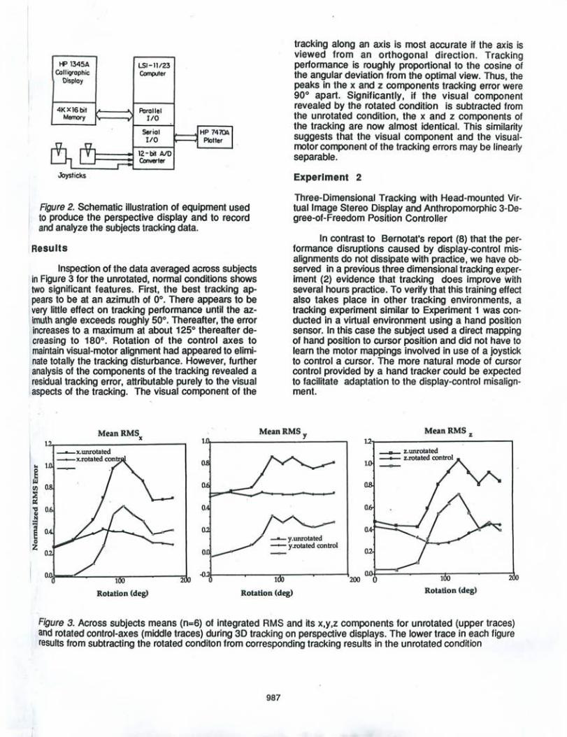
Figure 2. Schematic illustration of equipment used to produce the perspective display a,nd to record and analyze the subjects tracking data.
Results
Inspection of the data averaged across subjects in Figure 3 for the unrotated, normal conditions shows two significant features. First, the best tracking ap-
l pears to be at an azimuth of 0°. There appears to be very little effect on tracking performance until the azimuth angle exceeds roughly 50°. Thereafter, the error
I increases to a maximum at about 125° thereafter de[creasing to 180°. Rotation of the control axes to maintain visual-motor alignment had appeared to eliminate totally the tracking disturbance. However, further analysis of the components of the tracking revealed a residual tracking error, attributable purely to the visual aspects of the tracking. The visual component of the
MeanRMSx 1.
.. 1. 0
@ IOl 0 fIJ 0,
~ "a 0, O. III
.!:!
\1 0, 0
0 0
o. ~ .{). 1 2
tracking along an axis is most accurate if the axis is viewed from an orthogonal direction . Tracking performance is roughly proportional to the cosine of the angular deviation from the optimal view. Thus, the peaks in the x and z components tracking error were 90° apart. Significantly, if the visual component revealed by the rotated condition is subtracted from the unrotated condition, the x and z components of the tracking are now almost identical. This similarity suggests that the visual component and the visualmotor component of the tracking errors may be linearly separable.
Experiment 2
Three-Dimensional Tracking with Head-mounted Virtual Image Stereo Display and Anthropomorphic 3-Degree-of-Freedom Position Controller
In contrast to Bernotat's report (8) that the performance disruptions caused by display-control misalignments do not dissipate with practice, we have observed in a previous three dimensional tracking experiment (2) evidence that tracking does improve With several hours practice. To verify that this training effect also takes place in other tracking environments, a tracking experiment similar to Experiment 1 was conducted in a virtual environment using a hand position sensor. In this case the subject used a direct mapping of hand position to cursor position and did not have to learn the motor mappings involved in use of a joystick to control a cursor. The more natural mode of cursor control provided by a hand tracker could be expected to facilitate adaptation to the display-control misalignment.
MeanRMS y MeanRMS z l.2!"t"""------~-----,
2
Rotation (deg) Rotation (deg) Rotation (deg)
Figure 3. Across subjects means (n=6) of integrated RMS and its x,y,z components for unrotated (upper traces) and rotated control-axes (middle traces) during 3D tracking on perspective displays. The lower trace in each figure results from subtracting the rotated conditon from corresponding tracking results in the unrotated condition
987
Experiment 1
Three-dimensional Tracking with Perspective Display and Joystick Controllers
Methods
ThiS experimental setup was identical to that described in an earlier paper (9). The basic task was to control two, 2-axis joysticks to track the projection of a small diamond-shaped target that moved irregularly by sums of sines in three dimensions. The forcing functions in all three dimensions were determined so their spectrum resembled that of a first order, low pass filter with a cut-off at 0.1 Hz. Five different forcing functions were precomputed and randomly selected for a particular two minute tracking run. Subject's were given a ten second warm-up at the outset of each two-minute tracking run. The sampling frequency was 40.96 Hz.
The perspective projection on the screen was computed by an 11/23 computer at 20 Hz and displayed on a HP1345A stroke monitor. The cursor was a small cross displayed at half brightness. It was controlled in horizontal position by two axes of one joystick and in vertical position by the fore-aft axis of the other joystick. T.he tracking environment, a 5x5 line grid, was oriented to appear parallel to the floor and proVide a spatial reference for pursuit tracking. Four tracking errors were computed: Integrated normalized RMS between the target and cursor, and the separate x, y, and z components of this error. In normalized rootmean-square (RMS) tracking error a value of 1.0 corresponds to the error expected if no tracking is attempted while the cursor remains centered. If t is the target position and c is the cursor position and x = (x,y,z), the computed errors were:
,J ~IXc - Xe 2
RMS =-~--N~--
Similar1y for RMSy an:f RMSz
The view vector was pitched down 45° and the azimuth was rotated through 9 positions either cw or ccw to provide a variable amount of display and control misalignment. The central axis of the grid represented the X and Z coordinates of a Cartesian coordinate system. The experiment was conducted in a darkened room but the contours of the display case and other laboratory equipment were still easily visible and well into photopic vision. Subject's were seated 40 cm in
986
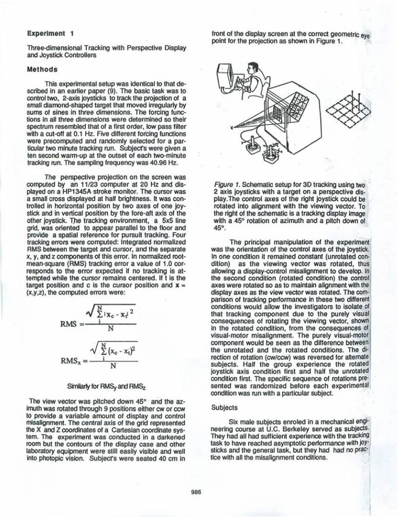
front of the display screen at the correct geometric eye point for the projection as shown in Figure 1.
Figure 1. Schematic setup for 3D tracking using two ' 2 axis joysticks with a target on a perspective display.The control axes of the right joystick could be rotated into alignment with the viewing vector. To . the right of the schematic is a tracking display image with a 45° rotation of azimuth and a pitch down of 45°.
The principal manipulation of the experiment was the orientation of the control axes of the joystick. In one condition it remained constant (unrotated condition) as the viewing vector was rotated, thus allowing a display-control misalignment to develop. In the second condition (rotated condition) the control axes were rotated so as to maintain alignment with the display axes as the view vector was rotated. The comparison of tracking performance in these two different conditions would allow the investigators to isolate of that tracking component due to the purely visual consequences of rotating the viewing vector, shown in the rotated condition, from the consequences of visual-motor misalignment. The purely visual-motor component would be seen as the difference between the unrotated and the rotated conditions. The direction of rotation (cw/ccw) was reversed for alternate subjects. Half the group experience the rotated joystick axis condition first and half the unrotated condition first. The specific sequence of rotations pre· sented was randomized before each experimental condition was run with a particular subject.
Subjects
Six male subjects enroled in a mechanical engineering course at U.C. Berkeley served as subjects. They had all had sufficient experience with the tracking task to have reached asymptotic performance with joysticks and the general task, but they had had no practice with all the misalignment conditions. _;
Methods
The earlier tracking studies (2) as well as Experiment 1 used 5 distinct target disturbance functions with the identical frequency content. The target functions were randomly selected for each run without the subject's knowledge. This second experiment which copied the dynamic and visual characteristics of the previous experiments, used unique forcing functions for each run. Use of unique functions for each run can rule out the remote possibility that subjects can learn the specific paths in the fixed target function.
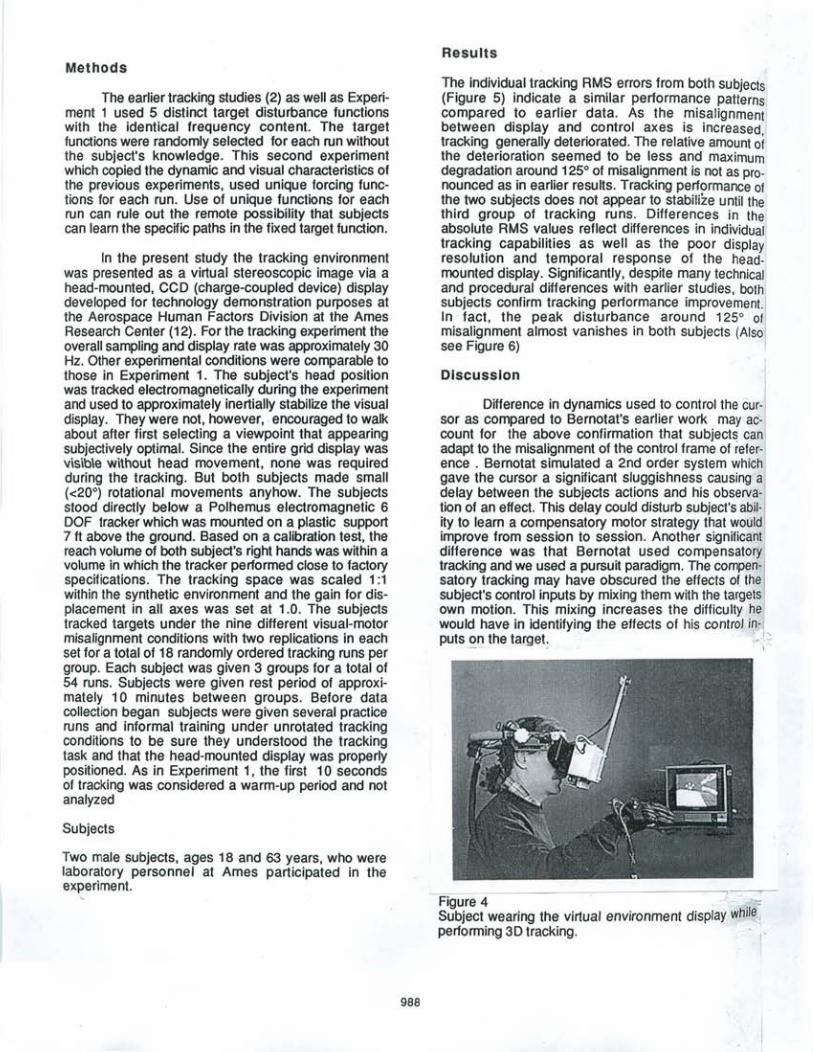
In the present study the tracking environment was presented as a virtual stereoscopic image via a head-mounted, CCD (charge-coupled device) display developed for technology demonstration purposes at the Aerospace Human Factors Division at the Ames Research Center (12). For the tracking experiment the overall sampling and display rate was approximately 30 Hz. Other experimental conditions were comparable to those in Experiment 1. The subject's head pOSition was tracked electromagnetically during the experiment and used to approximately inertially stabilize the visual display. They were not, however, encouraged to walk about after first selecting a viewpoint that appearing subjectively optimal. Since the entire grid display was visib\e without head movement, none was required during the tracking. But both subjects made small «20°) rotational movements anyhow. The subjects stood directly below a Polhemus electromagnetic 6 OaF tracker which was mounted on a plastic support 7 ft above the ground. Based on a calibration test, the reach volume of both subject's right hands was within a vQlume in which the tracker performed close to factory specifications. The tracking space was scaled 1:1 within the synthetic environment and the gain for displacement in all axes was set at 1.0. The subjects tracked targets under the nine different visual-motor misalignment conditions with two replications in each set for a total of 18 randomly ordered tracking runs per group. Each subject was given 3 groups for a total of 54 runs. Sl:Ibjects were given rest period of approximately 10 minutes between groups. Before data collection began subjects were given several practice runs and informal training under unrotated tracking conditions to be sure they understood the tracking task and that the head-mounted display was properly positioned. As in Experiment 1, the first 10 seconds of tracking was .considered a warm-up period and not analyzed
Subjects
Two male subjects, ages 18 and 63 years, who were laboratory personnel at Ames partiCipated in the experiment.
988
Results
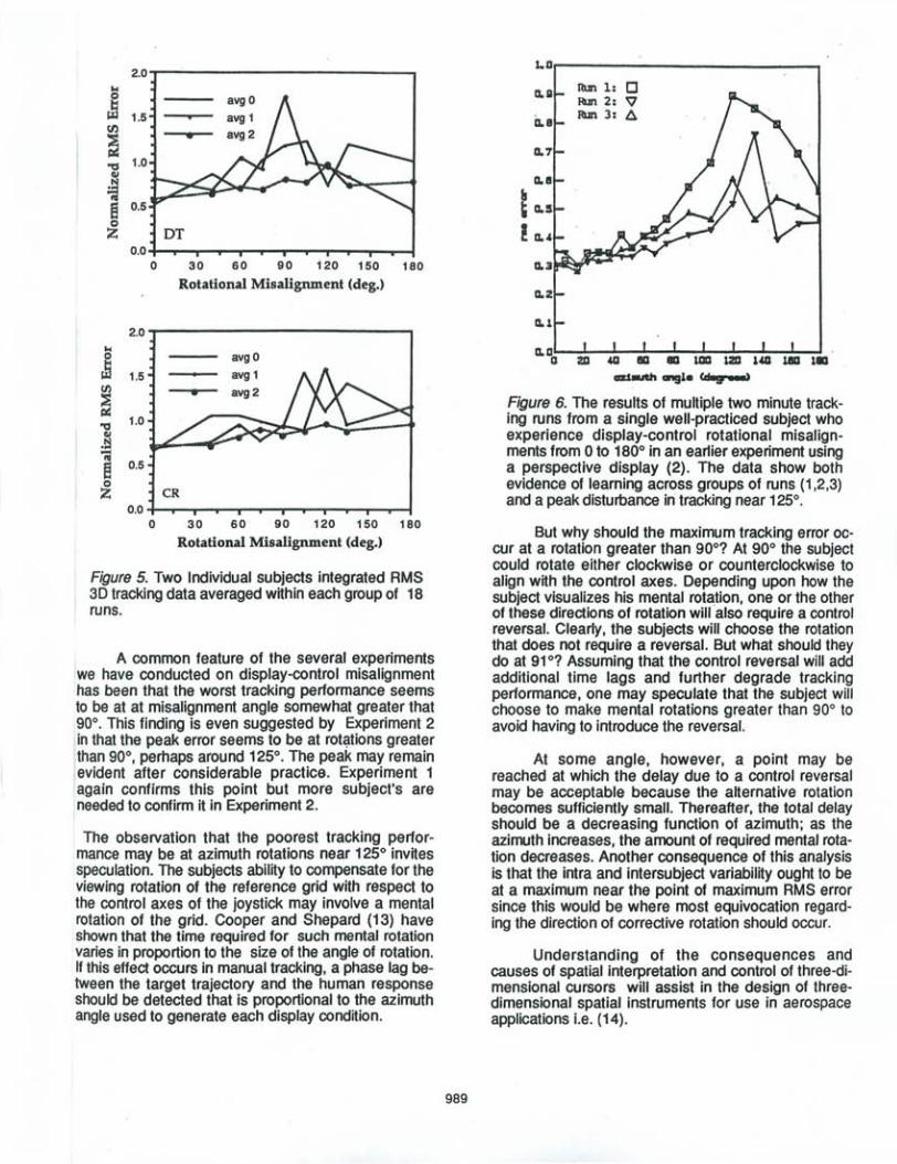
The individual tracking RMS errors from both subjects (Figure 5) indicate a similar performance patterns compared to earlier data. As the misalignment between display and control axes is increased tracking generally deteriorated. The relative amount 01 the deterioration seemed to be less and maximum degradation around 125° of misalignment is not as pronounced as in earlier results. Tracking performance of the two subjects does not appear to stabilize until the third group of tracking runs. Differences in the absolute RMS values reflect differences in individual tracking capabilities as well as the poor displaYJ resolution and temporal response of the headmounted display. Significantly, despite many technical and procedural differences with earlier studies, both subjects confirm tracking performance improvement. In . fact, the peak disturbance around 125° of misalignment almost vanishes in both subjects (Also see Figure 6)
Discussion
Difference in dynamiCS used to control the cursor as compared to Bernotat's earlier work may account for the above confirmation that subjects can adapt to the misalignment of the control frame of reference . Bemotat simulated a 2nd order system which gave the cursor a significant sluggishness causing a delay between the subjects actions and his observation of an effect. This delay could disturb subject's ability to learn a compensatory motor strategy that would improve from session to session. Another significant difference was that Bernotat used compensatory tracking and we used a pursuit paradigm. The compensatory tracking may have obscured the effects of the subject's control inputs by mixing them with the targets own motion. This mixing increases the difficulty he would have in identifying the effects of his control in-puts~11 the target ' I:::
Figure 4 . . I • --= Subject wearing the virtual environment display while performing 3D tracking.
2.0 ... Q avg 0 t: ~ 1.5 avg 1 fI) • avg 2
~ ~ 1.0 ell
~ e 0.5 Q
Z Dr 0.0
0 30 60 90 120 150 180
Rotational Misalignment (deg.)
2.0 ----------------,
'"' § ~ 1.5
~ '0 ell .!:j -;
1.0
8 0.5 Q
Z
avgO
CR 0.0 -I-................. --.---r--...--r-..,....-r-........ -r--...-!
o 30 60 90 120 150 180
Rotational Misalignment (deg.)
Figure 5. Two Individual subjects integrated RMS 3D tracking data averaged within each group of 18 runs.
A common feature of the several experiments we have conducted on display-control misalignment has been that the worst tracking performance seems to be at at misalignment angle somewhat greater that 90°. This finding is even suggested by Experiment 2 in that the peak error seems to be at rot~tions greater than 90°, perhaps around 125°. The peak may remain ,evident after considerable practice. Experiment 1 again confirms this point but more subject's are needed to confirm it in Experiment 2.
The observation that the poorest tracking performance may be at azimuth rotations near 125° invites speculation. The subjects ability to compensate for the viewing rotation of the reference grid with respect to the control axes of the joystick may involve a mental rotation of the grid. Cooper and Shepard (13) have shown that the time required for such mental rotation varies in proportion to the size of the angle of rotation. If this effect occurs in manual tracking, a phase lag between the target trajectory and the human response should be detected that is proportional to the azimuth angle used to generate each display condition.
989
La~---------___ ~ RIm 1: 0 IUl 2: "V ~ 3: A
a. 00 ZD .&G
ai..v. angl. 'd 9 aa:a)
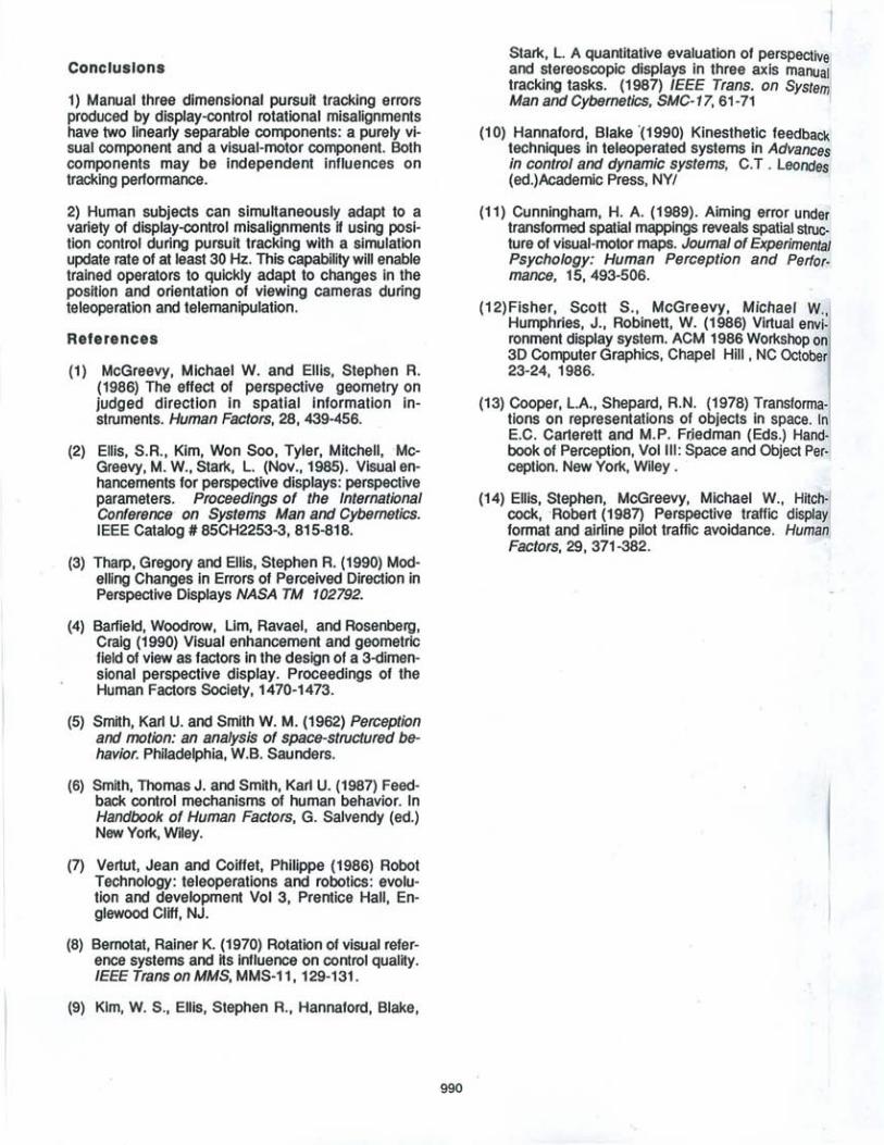
Figure 6. The results of multiple two minute tracking runs from a single well-practiced subject who experience display-control rotational misalignments from 0 to 180° in an earlier experiment using a perspective display (2). The data show both evidence of learning across groups of runs (1,2 ,3) and a peak disturbance in tracking near 125°.
But why should the maximum tracking error occur at a rotation greater than 90°? At 90° the subject could rotate either clockwise or counterclockwise to align with the control axes. Depending upon how the subject visualizes his mental rot~tion, one or the other of these directions of rotation will also require a control reversal. Clearly, the subjects will choose the rotation that does not require a reversal. But what should they do at 91°? Assuming that the control reversal will add additional time lags and further degrade tracking performance, one may speculate that the subject will choose to make mental rotations greater than 90° to avoid having to introduce the reversal.
At some angle, however, a point may be reached at which the delay due to a control reversal may be acceptable because the alternative rotation becomes sufficiently small. Thereafter, the total delay should be a decreasing function of azimuth; as the azimuth increases, the amount of required mental rotation decreases. Another consequence of this analysis is that the intra and intersubject variability ought to be at a maximum near the point of maximum RMS error since this would be where most equivocation regarding the direction of corrective rotation should occur.
Understanding of the consequences and causes of spatial interpretation and control of three-dimensional cursors will assist in the design of threedimensional spatial instruments for use in aerospace applications i.e. (14).
Conclusions
1) Manual three dimensional pursuit tracking errors produced by display-control rotational misalignments have two linearly separable components: a purely visual component and a visual-motor component. Both components may be independent influences on tracking performance.
2) Human subjects can simultaneously adapt to a variety of display-control misalignments if using position control during pursuit tracking with a simulation update rate of at least 30 Hz. This capability will enable trained operators to quickly adapt to changes in the position and orientation of viewing cameras during teleoperation and telemanipulation.
References
(1) McGreevy, Michael W. and Ellis, Stephen R. (1986) The effect of perspective geometry on judged direction in spatial information instruments. Human Factors, 28, 439-456.
(2) Ellis, S.R., Kim, Won Soo, Tyler, Mitchell, 'McGreevy, M. W., Stark, L. (Nov.,1985). Visual enhancements for perspective displays: perspective parameters. Proceedings of the International Conference' on Systems Man and Cybernetics. IEEE Catalog # 85CH2253-3, 815-818.
(3) Tharp, Gregory and Ellis, Stephen R. (1990) Modelling Changes in Errors of Perceived Direction in Perspective Displays NASA TM 102792.
(4) Barfield, Woodrow, Lim, Ravael, and Rosenberg, Craig (1990) Visual enhancement and geometric field of view as factors in the design of a 3-dimensional perspective display. Proceedings of the Human Factors Society, 1470-1473.
(5) Smith, Karl U. and Smith W. M. (1962) Perception and motion: an analysis of space-structured behavior. Philadelphia, W.B. Saunders.
(6) Smith, Thomas J. and Smith, Karl U. (1987) Feedback control mechanisms of human behavior. In Handbook of Human Factors, G . . Salvendy (ed.) New York, Wiley.
(7) Vertut, Jean and COiffet, Philippe (1986) Robot Technology: teleoperations and robotics: evolution and development Vol 3, Prentice Hall, Englewood Cliff, NJ.
(8) Bernotat, Rainer K. (1970) Rotation of visual reference systems and its influence on control quality. IEEE Trans on MMS, MMS-11, 129-131.
(9) Kim, W. S., Ellis, Stephen R., Hannaford, Blake,
990
Stark, L. A quantitative evaluation of perspective and stereoscopic displays in three axis manual tracking tasks. (1987) IEEE Trans. on System Man and Cybernetics, SMC-17, 61-71
(10) Hannaford, Blake '(1990) Kinesthetic feedback' techniques in teleoperated systems in Advances in control and dynamic systems, C. T . Leondes (ed.)Academic Press, NY/
(11) Cunningham, H. A. (1989). Aiming error under transformed spatial mappings reveals spatial structure of visual-motor maps. Journal of Experimental Psychology: Human Perception and Performance, 15, 493-506.
(12)Fisher, Scott S., McGreevy, Michael W., Humphries, J., Robinett, W. (1986) Virtual environment display system. ACM 1986 Workshop on 3D Computer Graphics, Chapel Hill, NC October 23-24, 1986.
(13) Cooper, L.A., Shepard, R.N. (1978) Transformations on representations of objects in space. In E.C. Carterett and M.P. Fr.iedman (Eds.) Handbook of Perception, Vol III: Space and Object Perception. New York, Wiley.
(14) Ellis, Stephen, McGreevy, Michael W., Hitchcock, -Robert (1987) Perspective traffic display format and airline pilot traffic avoidance. Human Factors, 29, 371-382.