Embed Size (px)
Citation preview

AAS 09-203
GYRO MISALIGNMENT DECOMPOSITIONAPPLIED TO MESSENGER CALIBRATION∗
Mark E. Pittelkau†
Daniel J. O’Shaughnessy‡
In attitude sensor misalignment estimation, a rotational misalignment vector, or alinear combination of rotational misalignments, must be constrained to zero for fullobservability. For this reason, one attitude sensor is generally designated the bodyreference sensor. Alternatively, the Inertial Measurement Unit (IMU) can be thebody reference sensor. A method for removal of a rotational misalignment from aRedundant IMU (RIMU), which has more than three sense axes, was developed re-cently. We demonstrate the method using telemetry from the MESSENGER space-craft. Results are compared with earlier results where one star tracker is the bodyreference sensor.
INTRODUCTION
The MErcury Surface, Space ENvironment, GEochemistry, and Ranging(MESSENGER) space-craft was launched on 3 August 2004 to enter an orbit around Mercury in March 2011. The MES-SENGER spacecraft carries two Galileo Avionica Autonomous Star Trackers, designated STA andSTB, and a Northrop Grumman Space Inertial Reference Unit (SIRU) for attitude determination.Each star tracker provides attitude measurements at a sample rate of 10 Hz, a16.4◦ circular field ofview, and has a specified end-of-life accuracy at 0.5 deg/sec of 4.5 arcsec1σ cross-boresight and41 arcsec1σ around its boresight. The present cross-boresight accuracy of thestar trackers appearsto be about 3.2 arcsec (cross-boresight) and 29 arcsec (boresight)for 9 tracked stars. The SIRU com-prises four hemispherical resonator gyroscopes (HRGs) and provides integrated rate measurementsfrom the four sense axes at a sample rate of 100 Hz.
In attitude sensor misalignment estimation, one rotational (absolute) misalignment vector, or alinear combination of rotational misalignments of the attitude sensors, has to be constrained to zeroso that the rotational misalignment vectors are fully observable. For this reason, one attitude sensoris generally designated the body reference sensor, or “master” or “fiducial” sensor, which is notparameterized with a rotational misalignment [1]. This method was used to produce calibrationresults using telemetry from MESSENGER [2], where one of the star trackers was selected to bethe body reference sensor.
Alternatively, the Inertial Measurement Unit (IMU) can be made the body reference sensor byremoving the rotational misalignment from the gyro axis misalignments. Eliminating the rotational
∗Copyright c© 2008 by the author. Permission to publish granted to The American Astronautical Society.†Consultant, Aerospace Control Systems LLC, 35215 Greyfriar Drive, Round Hill, Virginia 20141-2395.Tel: 540-751-1110 E-mail:[email protected], URL: http://www.acsinnovations.com/.Associate Fellow AIAA, Senior Member IEEE.
‡Senior Staff, The Johns Hopkins University Applied Physics Laboratory, Laurel, MD. Tel: 240-228-3807,E-mail: [email protected]
1

misalignment from a nominally orthogonal three-axis IMU is easy to do [3]. For a Redundant IMU(RIMU), which has more than three sense axes, elimination of the rotational misalignment is nottrivial. An algorithm to separate rotational and non-orthogonal misalignmentswas developed [4]for a RIMU and for an IMU with three non-orthogonal sense axes. Theadvantages of makingthe IMU the body reference sensor are that it does not become occultedas can happen with startrackers, and the alignment between the IMU and payload may be more stable than between thestar trackers and payload. (The star trackers on MESSENGER should never be occulted due tooperational constraints, but the point stands.)
A general definition of relative misalignment was recently introduced, and ageneral formulafor eliminating the unobservable absolute misalignment was developed [5]. This general formulaimposes a constraint on the misalignments of the attitude sensors and the IMU. The weighting co-efficients in the constraint matrix can be chosen such that the relative misalignments are “centered”about the average misalignment, or the coefficients can be chosen so that one of the attitude sensorsor the IMU is the body reference sensor. This approach will be investigated in a sequel paper.
In this paper, we present star tracker alignment and IMU calibration estimates from the RedundantIMU Attitude Determination/Calibration (RADICALTM) filter and telemetry from MESSENGER,and we compare the results with those reported in [2]. In these results, the IMU (the SIRU) isthe body reference sensor and the star tracker misalignments are relativeto the IMU. The relativemisalignment between the two star trackers is computed from the misalignment relative to the IMUand compared to previous results [2].
The results in this paper are intended to illustrate the efficacy of the RADICALcalibration filterand recent advances in calibration, and to provide apro bono independent analysis of the attitudesensor and gyro calibration on MESSENGER.
RADICAL ATTITUDE DETERMINATION/CALIBRATION FILTER
The RADICAL filter [6] estimates a full set of calibration parameters forn ≥ 3 gyro axes andm attitude sensors. The filter state vector includes 3 attitude perturbation states,n gyro biases,nsymmetric scale factor errors,n asymmetric scale factor errors,2n gyro axis misalignments,3m at-titude sensor misalignments, and optionallyn quantization states. The RADICAL software, whichis written in C, comprises core filter functions; a command interpreter; pre-processing; data ingest,synchronization, and buffering functions; and Matlab support software for sensor simulation and forplotting and tabulating results. The core filter functions include Extended Kalman Filter functions, acommand interface, telemetry interface, initialization for cold and warm start, processing of disjointtelemetry streams, default and active parameter tables, advanced measurement error models, parityresidual (null space measurement) update for full observability of the gyro calibration parameters,fault detection and performance monitoring functions, diagnostic output data, telemetry output in achoice of three different size but customizable packets, and several other features. The covariancematrix in a calibration filter can become ill conditioned during its initial convergence and in othersituations. Therefore UD-factorized covariance algorithms are used in RADICAL to ensure numer-ical stability and accuracy. The covariance matrix is never computed, except that certain elements ofthe covariance matrix are computed only for output and for convergencethreshold tests. RADICALis suitable for real-time on-board calibration, automated ground-based processing of telemetry, anddesktop analysis and design. The RADICAL filter has been used to support NASA, military, andcommercial spacecraft. The RADICAL filter was instrumental in anomaly resolution, performanceverification, and provisional ground-based processing of attitude telemetry for GeoEye-1.
2

For ground-based processing and desktop analysis, the Command Interpreter provides a powerfuland flexible command-line user interface. The Command Interpreter reads one or more script filesthat tell the interpreter how to execute the RADICAL filter. Commands may also beinput manuallyor from another program, which can include commands to read script files.The script files can benested. The Command Interpreter gives the user considerable flexibility to perform various opera-tions during processing of telemetry data without having to modify code. The scripting commandsare fairly simple in function and format. The commands define telemetry, parameter, and output filenames and locations, control execution of the filter, and interaction with the filter at specified timesduring processing. Wildcards are defined to simplify the specification of filenames.
One feature of the RADICAL calibration filter is that it can process disjoint or interrupted teleme-try streams and telemetry in multiple files. This capability was demonstrated in a previous paper[2]. The attitude estimate, attitude covariance, and attitude cross-covariance are reset when there isa break in the gyro data. The parameter covariance remains intact (in UD factorized form). Thisis called a “warm-start” of the calibration filter. In addition, a covariance “bump” can be appliedto model uncertainty due to a change in parameters since the epoch of the previously processedtelemetry stream. (A covariance bump can be applied at any time during processing in RADICAL.)A bump can also be applied to the attitude covariance. The covariance bump is simply a specifiedincrease in the covariance of any estimated parameter or attitude, and is applied upon a warm-startor at any time upon command. The bump is applied directly to the UD factors of the covariancematrix to ensure numerical accuracy and stability and for computational efficiency. The importanceof being able to process disjoint telemetry streams and applying the covariance bump is that thefilter does not have to be reinitialized, and the filter is nearly converged when the prior convergedestimates and their covariance are used to warm-start the filter. This can be of benefit in autonomouson-board calibration. Convergence problems are avoided when a priorestimate and a small prior co-variance are used to warm-start the filter, and a shorter calibration maneuver may then be sufficientto maintain convergence of the calibration parameters and their covariance.This can be of benefitduring mission operations to reduce risk (for example, in the hot solar environment at Mercury),to reduce interruption of science operations, and to reduce the volume of telemetry dedicated tocalibration. The warm-start feature permits a calibration maneuver to be segmented under certainoperational constraints.
RIMU MISALIGNMENT VECTOR DECOMPOSITION
Let wi be the nominal sense axis direction vectors for the gyros in a RIMU, and letthe vectorsui
andvi form an orthogonal triad withwi as shown in Figure1. To measure three-axis angular rate,we have to assume that thewi do not lie in a plane. The nonunique orthonormal vectorsui andvi
can be computed easily in a number of ways [1, 7]. The gyro axis misalignments are small-anglerotationsδui
aboutvi andδviaboutui, and the true sense axis direction vectorswi are modeled by
small-angle rotations of the nominalwi about the vectorsui andvi so thatwi = wi−δuivi−δviui.Define the2n × 1 vector of misalignments
δg =
[
δu
δv
]
(1)
whereδu = [δu1, δu2, . . . , δun]T andδv = [δv1, δv2, . . . , δvn]
T . The general misalignmentvector δg can be decomposed into a rotational misalignment common to all the gyro axes andnonorthogonal misalignments of the gyro axes. The rotational misalignment comprises 3 parame-ters, and the non-orthogonal misalignments comprise2n − 3 parameters. Although the conceptual
3

v
w
u
δuδv
w_
δ
δu u − δvv
Figure 1 Gyro Axis Misalignment
meaning of the term “non-orthogonal” is a bit blurry with regard ton ≥ 3 non-orthogonal senseaxes, the term is retained due to analogy with a decomposition for 3 orthogonal sense axes [3].
The algorithm to separate rotational and non-orthogonal misalignments is summarized here. Thegeometry of a RIMU can be defined by the3 × n matricesU , V , andW , where
U = [u1 u2 · · · un] V = [v1 v2 · · · vn] W = [w1 w2 · · · wn] (2)
Define the2n× 3 matrixY = [U −V ]T . An orthogonal basisQ1 for Y can be obtained from theQR factorization ofY such that
Y = QR = [Q1 Q2]
[
R1
0
]
= Q1R1 (3)
whereQ is a2n × 2n orthogonal matrix partitioned into a2n × 3 matrixQ1 and a2n × (2n − 3)matrixQ2. The3×3 upper triangular matrixR1 is nonsingular because thewi do not lie in a plane.
The2n×1 vector of misalignmentsδg can be expressed as a linear combination of a3×1 vectorof rotational misalignmentsδr and a(2n − 3) × 1 vector of non-orthogonal misalignmentsδn,
δg = [Y Q2]
[
δr
δn
]
(4)
The rotational and nonorthogonal misalignments can be computed from the general misalignmentvector by
[
δr
δn
]
= [Y Q2]−1δg =
[
Y †
QT2
]
δg (5)
whereY † = R−1
1QT
1is the pseudoinverse ofY .
The RADICAL calibration filter estimates the full misalignment vectorδg. If we want to makethe RIMU the body-reference sensor, we have to eliminate the rotational misalignment fromδg. Therotational misalignmentδr of the RIMU can be explicitly eliminated from the calibration model byusing Eq. (4). However, this leads to a computationally less efficient filter. We can implicitly elim-inateδr from the model by setting the initial covariance ofδr to a small value such as 0.001 arcsec(ideally zero but for numerical problems that would occur in the covariance update in a Kalmanfilter) and by setting the initial estimate ofδr to zero. (Estimates of a quantity are denoted by a
4

caret.) Then a linear combination ofδg, namelyδr = Y †δg, will remain close to zero during theestimation process. The covariance of the initial estimate of the general misalignment parametervector, in terms of the covariance of the rotational and nonorthogonal misalignments, is
cov(δg) = Pg = [Y Q2]
[
Pr 00 Pn
]
[Y Q2]T
= Y PrYT + Q2PnQ
T2 (6)
wherePr andPn are the covariance of error in the initial estimate of the rotational and nonorthog-onal misalignment parameter vectorsδr andδn. For lack of better information, we have assumedthat errors in the initial estimate of these vectors are uncorrelated, and soPr andPn are generallydiagonal matrices.
Given a covariance matrixPg of δg, we can compute the covariance and cross covariance ofPr
andPn by
cov
(
[
δr
δn
]
)
=
[
Pr Prn
Pnr Pn
]
=
[
Y †
QT2
]
Pg
[
Y †
QT2
]T
(7)
RELATIVE MISALIGNMENTS
The misalignment of STB relative to STA was estimated in a previous analysis of MESSENGERtelemetry [2], where STA was the body reference sensor. Here, we make the IMU the body referencesensor and we estimate the misalignment of STA and STB relative to the IMU. Themisalignmentof STB relative to STA, in the STB frame, is given by
δB/A = δB − TSTBSTAδA +
1
2δB × TSTB
STAδA (8)
whereδA andδB are the misalignments of STA and STB relative to the IMU and are expressed inthe frames of STA and STB, respectively; frame notation is only partially shown in Eq. (8). Define
δ =
[
δAδB
]
and Pδ = cov(δ) (9)
The covariance of the relative misalignment is given by
cov(δB/A) = [−TSTBSTA I] Pδ [−TSTB
STA I]T (10)
whereTSTBSTA is the transformation from the STA frame to the STB frame. Equation (8) is only a
second-order approximation, which is sufficient for computing the covariance, but is not sufficientlyaccurate for computing the relative misalignment vector when the misalignments are large.
It should be noted that the nominal IMU geometry matrix, which is from the IMU vendor’s cali-bration, contains a small rotational misalignment. Ths misalignment is not included inthe estimatedδA andδB, although variations in the rotational misalignment of the IMU will appear inδA andδB.The rotational misalignment in the nominal IMU geometry matrix is inconsequential incomputingthe relative misalignment of the star trackers.
5

CALIBRATION MANEUVER
The calibration maneuver is designed so that the calibration parameters are distinguishable inthe measurements. The maneuvers are quite restricted because of thermal requirements. Inside of0.85 AU they-axis of the spacecraft must be within 12 degrees of the direction to the Sun. Theactual calibration maneuver from 2006216 (year 2006 and day-of-year 216), where the spacecraftis within 0.85 AU, is shown in Figure2a. Calibration maneuvers on 2005300 and 2005301 arenearly the same and so are not shown. These maneuver sequences are±10 deg about thex-axis,±10 deg about thez-axis, and±360 deg about they-axis. The±360 deg rotation about thez-axismakes the calibration maneuver excessively long. It will be seen in the results that the calibrationparameters have mostly converged in 60 min, just after they-axis angular rate changes sign. Ashorter calibration maneuver, shown in Figure2b, was performed on 2007262. As will be seen, thismaneuver is almost as effective as the longer maneuver in terms of parameterestimation accuracy.Both of these maneuvers step and settle to±0.3 deg/sec. For sinusoidal maneuvers, it can beshown that doubling the angle of rotation decreases the parameter estimation error by1/
√2 whereas
doubling the angular rate decreases the parameter estimation error by 1/2. However, the period ofthe maneuver is important also. A similar result should hold for piecewise-constant maneuvers.
−0.5
0
0.5
x
−0.5
0
0.5
An
gu
lar
Ra
te (
de
g/s
ec)
y
0 50 100 150 200 250−0.5
0
0.5
z
Time (minutes)
−0.5
0
0.5
x
−0.5
0
0.5
An
gu
lar
Ra
te (
de
g/s
ec)
y
0 1000 2000 3000 4000−0.5
0
0.5
z
Time (seconds)
(a) (b)
Figure 2 (a) Calibration maneuvers on 2005300, 2005301, 2006216, and (b) 2007262.
CALIBRATION RESULTS
The initial misalignment estimates are zero and are assumed to be uncorrelated.The standarddeviation of error in the initial estimate of the star tracker misalignment is 1800 arcsec per axis foreach star tracker. The standard deviation of error in the initial estimateδn of the nonorthogonalitymisalignment is 360 arcsec for each of its components. The standard deviation of error in the initialestimateδr of the rotational misalignment is 0.001 arcsec per axis. The covariance of the gyro axismisalignment vector is initialized according to (7), wherePr = cov(δr) andPn = cov(δn). Thus,no rotational misalignment is estimated at the IMU so that the rotational misalignments estimated atthe two star trackers are distinguishable in the measurements. The standard deviation of the process
6
noise for the IMU misalignments was set to 0.0001 arcsec/hr1/2 per axis. The standard deviation ofthe process noise for the star tracker misalignments was set to 0.12 arcsec/hr1/2 per axis to permittracking of the thermally-varying misalignments. Other filter parameters are described in a previouspaper [2].
Star tracker and IMU telemetry from four calibration events (calibration maneuvers) were pro-cessed by the RADICAL attitude determination/calibration filter. These events occured on 2005300,2005301, 2006216, and 2007262. The IMU contains two power supplies, PPSMA and PPSMB. TheIMU was switched to PPSMB during the calibration event on 2005300, and then back to PPSMAprior to the next calibration event on 2005301. The IMU has remained on PPSMA since that time.Changing power supplies can significantly change the actual calibration parameters.
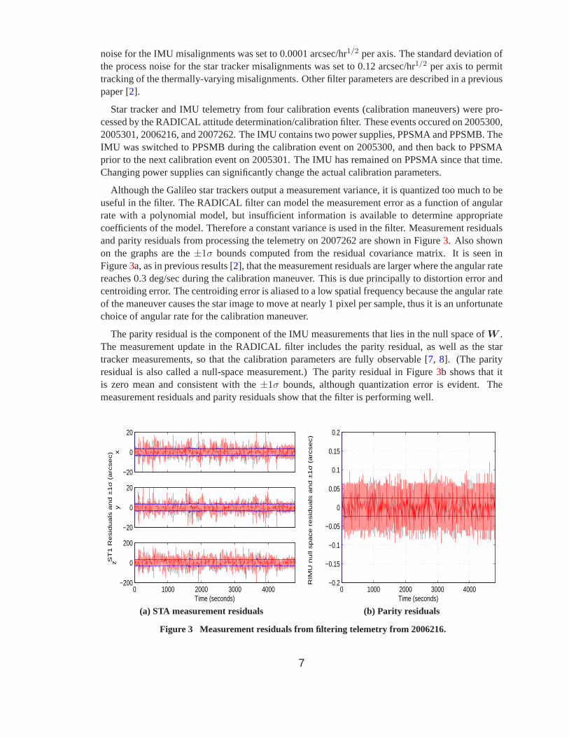
Although the Galileo star trackers output a measurement variance, it is quantized too much to beuseful in the filter. The RADICAL filter can model the measurement error asa function of angularrate with a polynomial model, but insufficient information is available to determine appropriatecoefficients of the model. Therefore a constant variance is used in the filter. Measurement residualsand parity residuals from processing the telemetry on 2007262 are shownin Figure3. Also shownon the graphs are the±1σ bounds computed from the residual covariance matrix. It is seen inFigure3a, as in previous results [2], that the measurement residuals are larger where the angular ratereaches 0.3 deg/sec during the calibration maneuver. This is due principallyto distortion error andcentroiding error. The centroiding error is aliased to a low spatial frequency because the angular rateof the maneuver causes the star image to move at nearly 1 pixel per sample, thus it is an unfortunatechoice of angular rate for the calibration maneuver.
The parity residual is the component of the IMU measurements that lies in the null space ofW .The measurement update in the RADICAL filter includes the parity residual, aswell as the startracker measurements, so that the calibration parameters are fully observable [7, 8]. (The parityresidual is also called a null-space measurement.) The parity residual in Figure 3b shows that itis zero mean and consistent with the±1σ bounds, although quantization error is evident. Themeasurement residuals and parity residuals show that the filter is performingwell.
−20
0
20
x
−20
0
20
ST
1 R
esid
ua
ls a
nd
±1σ
(a
rcse
c)
y
0 1000 2000 3000 4000−200
0
200
z
Time (seconds)0 1000 2000 3000 4000
−0.2
−0.15
−0.1
−0.05
0
0.05
0.1
0.15
0.2
Time (seconds)
RIM
U n
ull s
pa
ce
re
sid
ua
ls a
nd
±1σ
(a
rcse
c)
(a) STA measurement residuals (b) Parity residuals
Figure 3 Measurement residuals from filtering telemetry from2006216.
7

Star Tracker Misalignment Estimation
The final estimates of the star tracker misalignments from each calibration event are shown inTable1. Since the IMU is the body reference sensor, the misalignment estimates of thestar trackersproduced by the filter are relative to the IMU. Plots of the misalignments relativeto the IMU from2006216 are shown in Figure4. The variation in the misalignment is due to increasing baseplatetemperatures of STA and STB, since the thermal control system is designedfor single-tracker opera-tion. The baseplate temperatures were shown previously [2]. It is seen in Figure4c that the variationof the relative misalignment is due to changes in the alignment of STB relative to the IMU, whereasSTA appears to be stable in Figure4a. We can assume that the alignment of the IMU is stable sinceits baseplate temperature is constant.
The misalignment of STB relative to STA is computed by Eq. (8), and its covariance is computedby Eq. (10). These are shown in Figure5, and are very close to previous results where STA was thebody reference sensor [2].
STB was not turned on during the calibration maneuver that occured on 2007262. Therefore therelative misalignment between the star trackers cannot be estimated from the telemetry collectedon 2007262. Plots of the misalignment of STA relative to the IMU from 2007262 are shown inFigure6. This misalignment converges to a nearly constant value in each axis. A longer calibrationmaneuver, or one with larger angular rates or rotation angles, is needed for tighter convergence.
Table 1 Estimated star tracker misalignments and standard deviation, arcsec
Telemetryx-axis y-axis z-axis
δ1
σδ1δ2
σδ2δ3
σδ3
STA alignment relative to IMU2005300 812.85 0.31 357.70 0.72 −12.22 0.322005301 808.86 0.31 431.84 0.70 −18.11 0.312006216 814.40 0.31 436.80 0.69 −15.59 0.312007262 797.07 0.55 395.89 1.20 −11.33 0.49
STB alignment relative to IMU2005300 966.02 0.72 176.15 0.32 −440.40 0.342005301 893.53 0.70 173.09 0.32 −444.43 0.332006216 894.72 0.69 179.32 0.32 −444.86 0.332007262 0.00 0.00 0.00
STB alignment relative to STA2005300 1323.07 0.06 −637.00 0.06 −428.96 0.182005301 1324.72 0.06 −636.13 0.06 −426.96 0.182006216 1330.87 0.06 −635.43 0.06 −429.90 0.18
8

800
810
820
x
430
440
450
ST
1 M
isa
lig
nm
en
t (δ
a1)
estim
ate
s (
arc
se
c)
y
0 50 100 150 200 250−20
−10
0
z
Time (minutes)
0
1
2
x
0
1
2
ST
1 M
isa
lig
nm
en
t (δ
a1)
σ (
arc
se
c)
y
0 50 100 150 200 2500
1
2
z
Time (minutes)
(a) STA-IMU relative misalignment (b) STA-IMU standard deviation of estimation error
890
900
910
920
x
160
170
180
ST
2 M
isa
lig
nm
en
t (δ
a2)
estim
ate
s (
arc
se
c)
y
0 50 100 150 200 250−450
−440
−430
z
Time (minutes)
0
1
2
x
0
1
2
ST
2 M
isa
lig
nm
en
t (δ
a2)
σ (
arc
se
c)
y
0 50 100 150 200 2500
1
2
z
Time (minutes)
(c) STB-IMU relative misalignment (d) STB-IMU standard deviation of estimation error
Figure 4 Star tracker misalignments and standard deviationfrom 2006216.
9

1330
1340
1350
1360
x
−650
−640
−630
Re
lative
ST
Mis
alig
nm
en
t (δ
2/1
) e
stim
ate
s (
arc
se
c)
y
0 50 100 150 200 250−440
−430
−420
z
Time (minutes)
0
1
2
x
0
1
2
Re
lative
ST
Mis
alig
nm
en
t (δ
2/1
) σ
(a
rcse
c)
y
0 50 100 150 200 2500
1
2
z
Time (minutes)
(a) STB-STA relative misalignment (b) STB-STA standard deviation of estimation error
Figure 5 Misalignment of STB relative to STA from 2006216.
780
790
800
810
x
380
390
400
410
ST
1 M
isa
lig
nm
en
t (δ
a1)
estim
ate
s (
arc
se
c)
y
0 1000 2000 3000 4000−20
−10
0
10
z
Time (seconds)
0
1
2
x
0
1
2
ST
1 M
isa
lig
nm
en
t (δ
a1)
σ (
arc
se
c)
y
0 1000 2000 3000 40000
1
2
z
Time (seconds)
(a) STA-IMU relative misalignment (b) STA-IMU standard deviation of estimation error
Figure 6 Misalignment of STA relative to IMU from 2007262.
10
Gyro Axis Misalignment Estimation
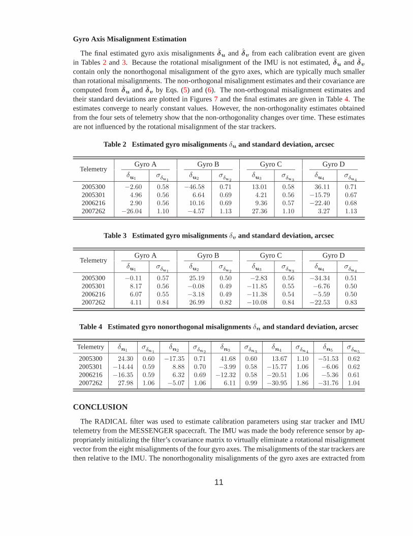
The final estimated gyro axis misalignmentsδu and δv from each calibration event are givenin Tables2 and3. Because the rotational misalignment of the IMU is not estimated,δu and δv
contain only the nonorthogonal misalignment of the gyro axes, which are typically much smallerthan rotational misalignments. The non-orthogonal misalignment estimates and their covariance arecomputed fromδu and δv by Eqs. (5) and (6). The non-orthogonal misalignment estimates andtheir standard deviations are plotted in Figures7 and the final estimates are given in Table4. Theestimates converge to nearly constant values. However, the non-orthogonality estimates obtainedfrom the four sets of telemetry show that the non-orthogonality changes over time. These estimatesare not influenced by the rotational misalignment of the star trackers.
Table 2 Estimated gyro misalignmentsδu and standard deviation, arcsec
TelemetryGyro A Gyro B Gyro C Gyro D
δu1σδu1
δu2σδu2
δu3σδu3
δu4σδu4
2005300 −2.60 0.58 −46.58 0.71 13.01 0.58 36.11 0.712005301 4.96 0.56 6.64 0.69 4.21 0.56 −15.79 0.672006216 2.90 0.56 10.16 0.69 9.36 0.57 −22.40 0.682007262 −26.04 1.10 −4.57 1.13 27.36 1.10 3.27 1.13
Table 3 Estimated gyro misalignmentsδv and standard deviation, arcsec
TelemetryGyro A Gyro B Gyro C Gyro D
δu1σδu1
δu2σδu2
δu3σδu3
δu4σδu4
2005300 −0.11 0.57 25.19 0.50 −2.83 0.56 −34.34 0.512005301 8.17 0.56 −0.08 0.49 −11.85 0.55 −6.76 0.502006216 6.07 0.55 −3.18 0.49 −11.38 0.54 −5.59 0.502007262 4.11 0.84 26.99 0.82 −10.08 0.84 −22.53 0.83
Table 4 Estimated gyro nonorthogonal misalignmentsδn and standard deviation, arcsec
Telemetry δn1σδn1
δn2σδn2
δn3σδn3
δn4σδn4
δn5σδn5
2005300 24.30 0.60 −17.35 0.71 41.68 0.60 13.67 1.10 −51.53 0.622005301 −14.44 0.59 8.88 0.70 −3.99 0.58 −15.77 1.06 −6.06 0.622006216 −16.35 0.59 6.32 0.69 −12.32 0.58 −20.51 1.06 −5.36 0.612007262 27.98 1.06 −5.07 1.06 6.11 0.99 −30.95 1.86 −31.76 1.04
CONCLUSION
The RADICAL filter was used to estimate calibration parameters using star tracker and IMUtelemetry from the MESSENGER spacecraft. The IMU was made the body reference sensor by ap-propriately initializing the filter’s covariance matrix to virtually eliminate a rotational misalignmentvector from the eight misalignments of the four gyro axes. The misalignments ofthe star trackers arethen relative to the IMU. The nonorthogonality misalignments of the gyro axes are extracted from
11

−500
50
axis
1−50
050
axis
2
−500
50
axis
3
−500
50
axis
4
0 1000 2000 3000 4000−50
050
axis
5
Time (seconds)
Gyro
no
no
rth
og
on
ality
(g
n)
estim
ate
s (
arc
se
c)
0
5
axis
1
0
5
axis
2
0
5
axis
3
0
5
axis
4
0 1000 2000 3000 40000
5
axis
5
Time (seconds)
Gyro
no
no
rth
og
on
ality
(g
n)
σ (
arc
se
c)
(a) Nonorthogonality misalignment estimate (b) Standard deviation of estimation error
Figure 7 Gyro axis nonorthogonality misalignment estimateand standard deviation from 2007262.
the gyro axis misalignments by a linear mapping. Results show that the estimated misalignmentsof the star trackers relative to the IMU are accurate to about 0.2 to 0.7 arcsec1σ. Furthermore theestimated relative misalignment between the star trackers, computed from tracker misalignmentsrelative to the IMU, is the same as the relative misalignment estimated when a star tracker is thebody reference sensor and are accurate to about 0.1 arcsec1σ.
Although the rotational misalignment could be explicitly eliminated from the filter, thusparam-eterizing the gyro axis misalignments with nonorthogonal misalignments and making the IMU thebody reference sensor, this approach seems to complicate the calibration algorithm. An alternativeapproach [5] involving a constraint on the absolute misalignments may offer greater utility withoutgreatly increasing the complexity of the calibration filter.
The results in this paper show that star tracker B on MESSENGER is subjectto thermal deflection,and that star tracker A is stable with respect to the IMU. The thermo-mechanical design of thestar tracker mountings should be reviewed to explain this finding. The radiator is designed foroperation with only one star tracker on, so the baseplate temperatures of both star trackers risewhen both star trackers are on. It should be emphasized that the attitude estimation performanceon MESSENGER is adequate. This work serves to gain a greater understanding of the designand potential performance of the system and at the same time to demonstrate the capabilities andperformance of the RADICAL attitude determination/calibration filter.
ACKNOWLEDGEMENT
The authors thank Dr. Sean Solomon of the Carnegie Institution of Washington, and Dr. TomStrikwerda and Dr. Wayne Dellinger of the Applied Physics Laboratory, for providing telemetrydata and support to conduct the analysis reported in this paper. This probono work was undertakenfor the mutual benefit of Aerospace Control Systems Engineering and Research, the Applied PhysicsLaboratory, and the MESSENGER mission.
12

REFERENCES
[1] Pittelkau, M. E., “Survey of Calibration Algorithms forSpacecraft Attitude Sensors and Gyros”, Astro-dynamics Specialist Conference, Mackinac Island, MI, Aug 2007. 1, 3
[2] O’Shaughnessy, D; Pittelkau, M. E., “Attitude Sensor and Gyro Calibration for MESSENGER”, 20thInternational Symposium on Space Flight Dynamics, 24–28 Sept 2007, Annapolis, MD.1, 2, 3, 5, 7, 8
[3] Pittelkau, M. E., “Everything Is Relative in System Alignment Calibration”,AIAA Journal of Spacecraftand Rockets, Vol. 39, No. 3, 2002, pp. 460–466.2, 4
[4] Pittelkau, M. E., “RIMU Misalignment Vector Decomposition”, AIAA-2004-4856, AAS/AIAA Astro-dynamics Specialist Conference, Providence, RI, 16–19 Aug2004. 2
[5] Pittelkau, M. E., “General Definition of Relative Misalignment”, Paper No. AAS 08-289, F. LandisMarkley Astronautical Symposium, Cambridge, MD, 29 June – 2July 2008, inAdvances in the Astro-nautical Sciences, Vol. 132, pp. 507–520.2, 12
[6] URL: http://www.acsinnovations.com/index_files/products.htm 2[7] Pittelkau, M. E., “Calibration and Attitude Determination with Redundant Inertial Measurement Units”,
AIAA Journal of Guidance, Control, and Dynamics, Vol. 28, No. 4, 2005, pp. 743–752.3, 7[8] Pittelkau, M. E., “Advances in Attitude Determination with Redundant Inertial Measurement Units”,
AAS Journal of the Astronautical Sciences, Vol. 54, Nos. 3 & 4, 2006 (Special Edition for the MalcolmD. Shuster Symposium).7
13