Embed Size (px)
Citation preview

Thomas Jefferson National Accelerator Facility
Page 1
CAM WBS STATUS
WBS 1.4.2 – Hall B
STATUS
September, 2012
L. Elouadrhiri

Thomas Jefferson National Accelerator Facility
Page 2
SVT Sensors and Pitch AdaptersSensors• Received from Hamamatsu all production batches. • Final production batch delivered Sep 26th.
• Sensors tests underway, will be completed by October 19th.• Meets or exceeds all specifications.• Excellent quality – 98.5% of sensors have no defective stripsPitch Adapters• Delivery of production batch is due by the end of October 2012.
Specification limit: 10 nA/cm2

Thomas Jefferson National Accelerator Facility
Page 3
SVT Slow Controls and Power SuppliesWiener MPOD High and Low Voltage Supplies• The first shipment of (2) crates, (2) LV cards, & (2) HV cards is due November 23rd. The
remaining (2) crates and modules is due ~ 2/15/2013.• Labview based remote control / monitoring code developed for two SVT modules.
Successfully tested remote control / monitoring code in lab and during beam test. • Monitoring system being developed for module production testing using tested code above as
a base.
Environmental Hardware / Monitors• Successfully tested National Instruments (NI) Field Point ADC’s with the Environmental
Labview monitoring code (module temp., ambient temperature and humidity) in the lab and during beam test.
• Testing NI CompactRIO ADC’s to replace Field Point ADC’s. Allows for stand alone monitoring. Capable of EPICS integration.
• VME based ADC’s on order for comparison to NI CompactRIO ADC’s

Thomas Jefferson National Accelerator Facility
Page 4
SVT Hybrid Flex Circuit Board (HFCB)
HFCB V1 HFCB V2
• HFCB V2 has been designed with removable alignment tabs.• Ground and Bias connections to the module will be soldered
with redundant tabs instead of wire bonds.Ground and Bias tab connections
Removable alignment tabs
• External Review Complete Jun 2012• Internal Review Completed Aug 2012• Submission to Manufacturer Sep 2012• Estimated Delivery Nov 2012

Thomas Jefferson National Accelerator Facility
Page 5
SVT DAQ SystemSVT DAQ is essentially the same as used in CLAS12 and GlueX, consisting of:
• Intel based VME Controller (4) Fully Received• Signal Distribution (4) Fully Received• Trigger Interface (4) Delivery by Feb. 2013• VSCM (40) Delivery by Oct. 6th 2013 (first articles)
Delivery by December 2012 (full production)• VXS Crates (4) Delivery as part of the Hall B order
(small quantities already received)VXS-Silicon-Readout-Module (VSCM) is the only “new” component in SVT DAQ compared to standard 12GeV design.
• Prototypes delivered in Spring of 2011 and used for SVT test run and test stands.• Prototypes needed additional features and improvements which were made in production design• Production design is complete• Production first articles expected 1st week of October 2012• Full production order received by end of 2012• Minor firmware changes needed for production version
to HFCB
VME readout

Thomas Jefferson National Accelerator Facility
Page 6
SVT Module performance testing• Electrical testing of the SVT modules is ongoing (procedures and
results are described in the SVT Commissioning document)• Calibration software for module production testing is being
developed• Ready to test the production versions of the HFCB and VSCM

Thomas Jefferson National Accelerator Facility
Page 7
SVT Commissioning• SVT Calibration and Commissioning document prepared• Commissioning plan will be presented at the CLAS12
collaboration meeting, Oct 10th
• Current commissioning activities include analysis of the beam test data, calibration with laser, cosmic rays, and gamma source
• Beam test with production grade modules is scheduled for 2013
Thomas Jefferson National Accelerator Facility
Page 8
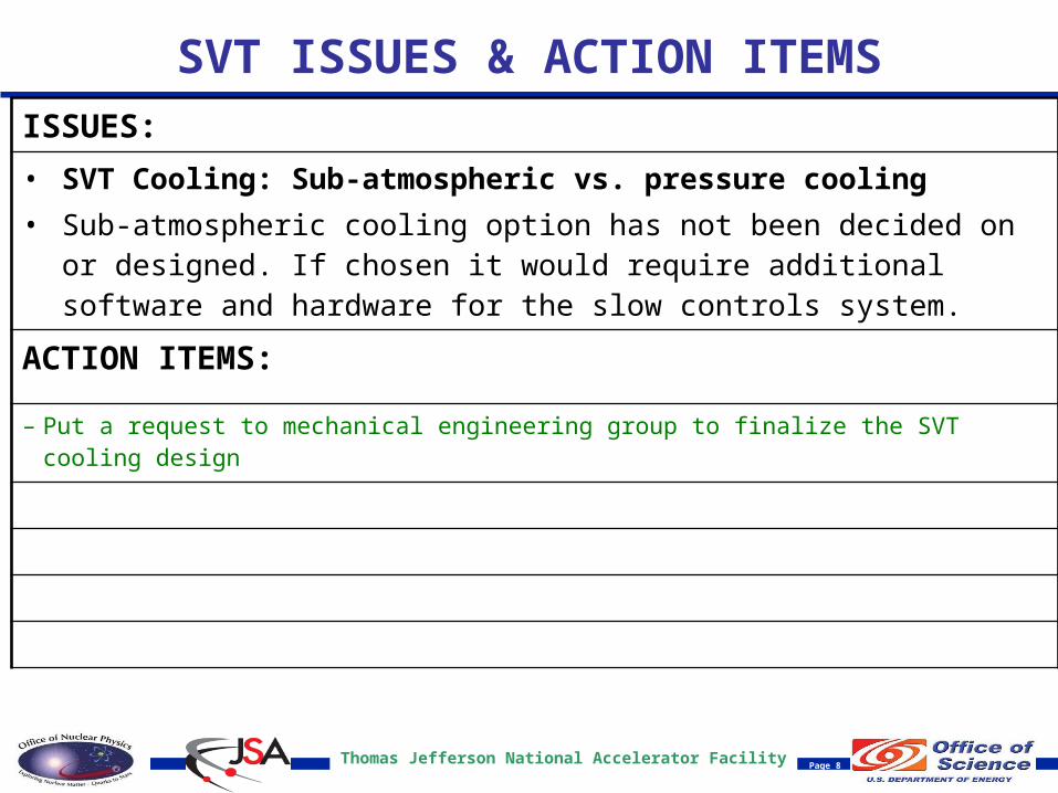
SVT ISSUES & ACTION ITEMSISSUES:
• SVT Cooling: Sub-atmospheric vs. pressure cooling• Sub-atmospheric cooling option has not been decided on or designed. If
chosen it would require additional software and hardware for the slow controls system.
ACTION ITEMS:
– Put a request to mechanical engineering group to finalize the SVT cooling design

Thomas Jefferson National Accelerator Facility
Page 9
SVT ISSUES & ACTION ITEMSISSUES: HFCB, Selection of Assembly Vendor
• 3 Vendors have been used for assembly of first article circuits or test boards.• Multiple vendors have had issues with solder migration and faulty solder
joints in the high density areas.• Over heating in flex areas.
ACTION ITEMS: Pre-qualification of Assembly Vendor
– Work with procurement to develop a process to pre-qualify assembly vendors.– Engineer protection which will eliminate the possibility of overheating flex areas and solder
migration during paste application and reflow.
Thomas Jefferson National Accelerator Facility
Page 10
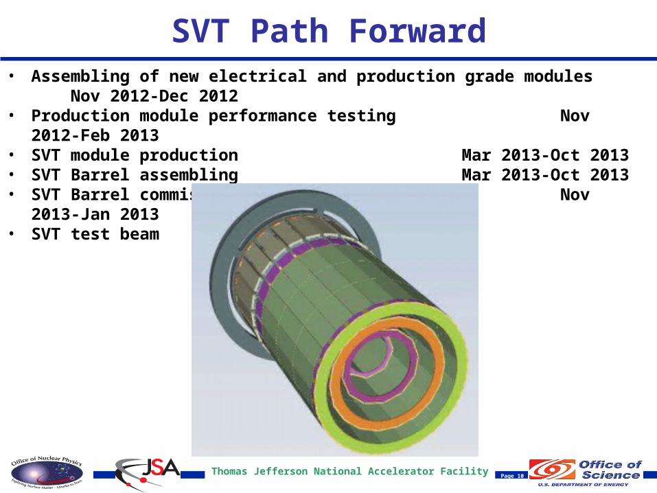
SVT Path Forward• Assembling of new electrical and production grade modules Nov 2012-Dec
2012• Production module performance testing Nov 2012-Feb
2013• SVT module production Mar 2013-Oct
2013• SVT Barrel assembling Mar 2013-Oct
2013• SVT Barrel commissioning with cosmic rays Nov 2013-Jan 2013• SVT test beam TBD 2013

Thomas Jefferson National Accelerator Facility
Page 11
Backup

Thomas Jefferson National Accelerator Facility
Page 12
Documentation• SVT testing Elog has over 400 entries• SVT TDR has been updated• SVT Calibration and Commissioning document prepared• SVT web page design is being reviewed

Thomas Jefferson National Accelerator Facility
Page 13
SVT Sensor Status

Thomas Jefferson National Accelerator Facility
Page 14
SVT Sensor Status

Thomas Jefferson National Accelerator Facility
Page 15
SVT Sensor Status

Thomas Jefferson National Accelerator Facility
Page 16
SVT Technical Review Recommendations
• I.4 - The team needs to revisit the grounding fundamentals of the input to the preamplifier.
• Experts in the fields of the FSSR2 chip design as well as silicon readout electronics were identified. A design strategy was developed, implemented and reviewed externally and internally.
• As per expert recommendation single ground net was used for the HFCB V2 design. However, the FSSR2 analog ground pads return directly to the substrate ground as close as possible to the chip.
• I.5 - The capacitor directly across the detector to ground needs to come back to the FSSR2 chip VERY close to pins 84 and 215 (GNDA). This is where we assume the sources of the input NFETs are connected. This directly affects the noise gain of the detector/preamplifier combination. The bias resistor, although not as critical, also needs to be very close to the aforementioned pins.
• As per expert recommendation this capacitor has been relocated to a position as close as possible to the chip input section. Additionally, the connection between the detector bias return and the FSSR2 substrate has also been similarly relocated.
• I.6 - The capacitors of the high voltage that are isolated from the actual detector by series resistors need to be close to the front end but are not as critical as the capacitor directly connected to the detector.
• As per expert recommendation this capacitor has been relocated to a position as close as possible to the chip input section.

Thomas Jefferson National Accelerator Facility
Page 17
SVT Technical Review Recommendations
• I.7 - The flex circuit vulnerabilities should be discussed with the vendor to evaluate the risks and mitigation procedures. The vendor should provide information regarding the quality assurance of plated-through holes. (The vendor should also be consulted about minimum bend radius guidelines.)
• Hall B Instrumentation made a visit to the chosen manufacturer (Compunetics) and this recommendation was discussed in detail as well as the proposed improvements to the design. They have provided documentation from the manufacture of the flexible cores and coverlays (DuPont) with information on out-gassing as it pertains to flex circuit material.
• Compunetics has provided input to design for consideration with regards to the manufacturability and long term stability of the circuit. Recommendations for layer core material thicknesses, coverlays, and through hole size and position were evaluated during layout were solicited by the Jlab designer from the engineering staff at Compunetics, FSSR2 chip designers, silicon detector electronics and micro-bonding experts.
• Compunetics recommended the build of a variety of mechanical mock ups using different 12 layer stack-ups to be used to evaluate the bend radius. These mechanical were built and fit tested by FNAL. A reference document on maintaining a feasible bend radius has been developed. The industry standard for minimum radius for dynamic bends in flex is 10 times the thickness, which can be reduced to as small as 4 times the thickness for a static one time bend.

Thomas Jefferson National Accelerator Facility
Page 18
SVT Technical Review Recommendations
• II.1 - A cohesive system test plan that addresses system issues should be developed, vetted, documented and carried out by the collaboration based on parts that are currently available and the delivery of multiple staves. Contact other groups (Valerio Re) who have had experience testing the FSSR2. We would recommend that the team supply the cable information and front-end layout to Re for his review and request from him his front-end board layout for the team’s review. Coherent noise and threshold dispersion should be measured under a variety of operating conditions with multiple modules. Understand the total noise in the prototype module. Determine the random and coherent component. Modify the design if necessary to eliminate coherent noise.
• In an effort to eliminate coherent noise the designers of FSSR2 as well as other experts in the field of silicon detector electronics have been consulted during the design process of the HFCB V2. In all there were more than 20 recommendations, all were followed. The design was externally and internally review prior to submission to the manufacturer. Some of the improvements suggested are as follows:
– Relocation of the detector bias capacitors to be closer to the analog input of the chip.– The separation of analog and digital supply to the FSSR2.– Direct connection of the FSSR2 analog return to the chip substrate prior to the substrate to ground plane connection.– The use of uninterrupted ground references.– Stitch guard traces for clock signals.– Split termination of clock signals and the reset signal.– Individual decoupling capacitor for each chip connection to the power plane and bulk capacitors for the hybrid low voltage planes.

Thomas Jefferson National Accelerator Facility
Page 19
HFCB Recommendations
Rec. I.4: Grounding Fundamentals of the Preamp: Circuit has single ground net. Chip analog ground returns to directly to substrate.
Rec. I.5 and I.6,: Relocation of bias caps and bias return to chip return resistor: All recommended passives relocated. Connections between bias return and chip return are done prior to plane connection.
Rec. II.2: Decoupling capacitors for all inputs: Each chip has 19 caps.

Thomas Jefferson National Accelerator Facility
Page 20
HFCB Recommendations
Guard Traces for clock signals: Each clock signal is isolated from other signals with stitched guards.

Thomas Jefferson National Accelerator Facility
Page 21
Pyralux Outgassing Summary (Rec. I.7)