Embed Size (px)
Citation preview
AMSC 18-001, PRELIMINARY FINAL DRAFT AMSC ROADMAP VERSION 2.0 4/6/18
America Makes & ANSI AMSC Standardization Roadmap for Additive Manufacturing Page 1 of 260
This page does not get printed – replace it with the Front Cover 1
2
Navigating through this document: 3
- Clicking in the table of contents takes you to the relevant page / section 4
- Opening the navigational pane will make it easier to navigate to individual 5
sections. 6
7
Printing the document: Note: This is a 260 page document. 8
9
Submitting Comments on the Roadmap: Comments on this draft should be sent 10
to [email protected] by May 3, 2018. Comments must be submitted using the 11
AMSC Comment Form (instructions provided separately). 12
13
14
Standardization Roadmap for Additive Manufacturing, Version 2.0 15
16
Preliminary Final Draft for Comment, dated 4/6/18 17
18
By the 19
20
America Makes & ANSI Additive Manufacturing Standardization 21
Collaborative (AMSC) 22
23
24
AMSC 18-001, PRELIMINARY FINAL DRAFT AMSC ROADMAP VERSION 2.0 4/6/18
America Makes & ANSI AMSC Standardization Roadmap for Additive Manufacturing Page 2 of 260
1
2
3
4
5
6
7
8
9
10
11
12
13
14
15
16
17
18
19
20
21
22
23
24
25
26
27
28
29
30
31
32
33
34
©2018 American National Standards Institute (ANSI)/National Center for Defense Manufacturing and 35
Machining, operating America Makes. All rights reserved. Published by ANSI and NCDMM /America 36
Makes. Printed in the United States of America. 37
38
This material may be copied without permission from ANSI or NCDMM/America Makes only if and to the 39
extent that the text is not altered in any fashion and the ANSI and NCDMM/America Makes copyright is 40
clearly noted. 41
42
Material in this publication is for educational purposes. Neither the publisher nor the authors assume 43
any liability for any errors or omissions or for how this publication or its contents are used or interpreted 44
or for any consequences resulting directly or indirectly from the use of this publication. For legal or 45
other advice, please consult your personal lawyer or the appropriate professional. 46
47
The views expressed by the individuals in this publication do not necessarily reflect the views shared by 48
the companies they are employed by (or the companies mentioned in this publication). The employment 49
status and affiliations of authors with the companies referenced are subject to change. 50
51
AMSC 18-001, PRELIMINARY FINAL DRAFT AMSC ROADMAP VERSION 2.0 4/6/18
America Makes & ANSI AMSC Standardization Roadmap for Additive Manufacturing Page 3 of 260
Table of Contents (Note: Page numbers and page breaks will be corrected in the final version.) 1
Acknowledgments ......................................................................................................................................... 7 2
Executive Summary ....................................................................................................................................... 9 3
Summary of Major Changes from Version 1.0 ............................................................................................ 11 4
Summary Table of Gaps and Recommendations ........................................................................................ 15 5
1. Introduction .............................................................................................................................. 45 6
1.1 Situational Assessment for AM ................................................................................................. 45 7
1.2 Roadmap Background and Objectives ...................................................................................... 46 8
1.3 How the Roadmap Was Developed .......................................................................................... 47 9
1.4 Roadmap Structure ................................................................................................................... 48 10
1.5 Overview of SDOs in the AM Space .......................................................................................... 49 11
1.5.1 Association for the Advancement of Medical Instrumentation (AAMI) ................................... 50 12
1.5.2 American Society of Mechanical Engineers (ASME) ................................................................. 50 13
1.5.3 ASTM International (ASTM) ...................................................................................................... 53 14
1.5.4 American Welding Society (AWS) ............................................................................................. 58 15
1.5.5 Institute for Electrical and Electronics Engineers (IEEE) ........................................................... 60 16
1.5.6 IPC – the Association Connecting Electronics Industries (IPC) ................................................. 66 17
1.5.7 International Organization for Standardization (ISO) ............................................................... 70 18
1.5.8 Medical Imaging & Technology Alliance (MITA) and Digital Imaging and Communications in 19
Medicine (DICOM) of the National Electrical Manufacturers Association (NEMA) ................. 74 20
1.5.9 Metal Powder Industries Federation (MPIF) ............................................................................ 75 21
1.5.10 MTConnect Institute (MTConnect) ........................................................................................... 78 22
1.5.11 SAE International (SAE) ............................................................................................................. 79 23
2. Gap Analysis of Standards and Specifications .......................................................................... 87 24
2.1 Design ....................................................................................................................................... 87 25
2.1.1 Introduction .............................................................................................................................. 87 26
2.1.2 Design Guides ........................................................................................................................... 87 27
2.1.3 Design Tools .............................................................................................................................. 94 28
2.1.4 Design for Specific Applications ................................................................................................ 97 29
2.1.4.1 Design for Assembly ............................................................................................................... 97 30
2.1.4.2 Design for Printed Electronics ................................................................................................ 98 31
2.1.4.3 Design for Medical ................................................................................................................. 99 32
2.1.5 Design Documentation ........................................................................................................... 105 33
2.1.6 Design Verification and Validation ......................................................................................... 115 34
2.1.7 Design for Anti-counterfeiting .................................................................................................... 119 35
AMSC 18-001, PRELIMINARY FINAL DRAFT AMSC ROADMAP VERSION 2.0 4/6/18
America Makes & ANSI AMSC Standardization Roadmap for Additive Manufacturing Page 4 of 260
2.2 Process and Materials ............................................................................................................. 120 1
2.2.1 Precursor Materials ................................................................................................................ 120 2
2.2.1.1 Introduction ......................................................................................................................... 120 3
2.2.1.2 Storage, Handling, and Transportation ................................................................................ 124 4
2.2.1.3 Characterization of Powders ................................................................................................ 125 5
2.2.1.3.1 Chemical Composition .............................................................................................. 126 6
2.2.1.3.2 Flowability ................................................................................................................. 128 7
2.2.1.3.3 Spreadability ............................................................................................................. 129 8
2.2.1.3.4 Density (Apparent vs. Tapped) .................................................................................. 130 9
2.2.1.3.5 Particle Size and Particle Size Distribution ................................................................ 130 10
2.2.1.3.6 Particle Morphology .................................................................................................. 131 11
2.2.1.3.7 Feedstock Sampling .................................................................................................. 132 12
2.2.1.3.8 Hollow Particles and Hollow Particles with Entrapped Gas ...................................... 134 13
2.2.1.3.9 AM Process-Specific Metal Powder Specifications ................................................... 135 14
2.2.1.4 Characterization of Material Extrusion Feedstock (Filaments & Pellets) ............................ 136 15
2.2.1.4.1 Chemical Composition .............................................................................................. 136 16
2.2.1.4.2 Geometry .................................................................................................................. 137 17
2.2.1.4.3 Melt Flow .................................................................................................................. 137 18
2.2.1.4.4 Moisture Content ...................................................................................................... 138 19
2.2.1.4.5 Thermal Stability ....................................................................................................... 138 20
2.2.1.5 Characterization of Liquid Feedstock ................................................................................... 139 21
2.2.1.5.1 Chemical Composition .............................................................................................. 139 22
2.2.1.5.2 Viscosity .................................................................................................................... 139 23
2.2.1.5.3 Feedstock Sampling .................................................................................................. 139 24
2.2.2 Process Control ....................................................................................................................... 140 25
2.2.2.1 Introduction ......................................................................................................................... 140 26
2.2.2.2 Digital Format and Digital System Control ........................................................................... 141 27
2.2.2.3 Machine Calibration and Preventative Maintenance .......................................................... 141 28
2.2.2.4 Machine Qualification .......................................................................................................... 144 29
2.2.2.5 Parameter Control ............................................................................................................... 145 30
2.2.2.6 Adverse Machine Environmental Conditions: Effect on Component Quality ...................... 146 31
2.2.2.7 Precursor Material Handling: Use, Re-use, Mixing, and Recycling Feedstock ..................... 147 32
2.2.2.8 Precursor Material Flow Monitoring.................................................................................... 150 33
2.2.2.9 Environmental Health and Safety: Protection of Machine Operators ................................. 151 34
2.2.2.10 Configuration Management: Cybersecurity...................................................................... 153 35
AMSC 18-001, PRELIMINARY FINAL DRAFT AMSC ROADMAP VERSION 2.0 4/6/18
America Makes & ANSI AMSC Standardization Roadmap for Additive Manufacturing Page 5 of 260
2.2.2.11 In-Process Monitoring ....................................................................................................... 154 1
2.2.2.12 Anti-Counterfeiting ........................................................................................................... 155 2
2.2.3 Post-processing ....................................................................................................................... 156 3
2.2.3.1 Introduction ......................................................................................................................... 156 4
2.2.3.2 Heat Treatment (metals, polymers) ..................................................................................... 157 5
2.2.3.3 Hot Isostatic Pressing (HIP) (metals) .................................................................................... 161 6
2.2.3.4 Surface Finish (Surface Texture) (metals, polymers) ........................................................... 164 7
2.2.3.5 Machining (metals, polymers) ............................................................................................. 169 8
2.2.3.6 Post-curing Methods (polymers) ......................................................................................... 169 9
2.2.4 Finished Material Properties .................................................................................................. 173 10
2.2.4.1 Introduction ......................................................................................................................... 173 11
2.2.4.2 Material Properties .............................................................................................................. 173 12
2.2.4.3 Component Testing .............................................................................................................. 178 13
2.2.4.4 Biocompatibility & Cleanliness of Medical Devices ............................................................. 179 14
2.2.4.5 Chemistry ............................................................................................................................. 180 15
2.2.4.6 Design Allowables ................................................................................................................ 182 16
2.2.4.7 Microstructure ..................................................................................................................... 186 17
2.3 Qualification & Certification ................................................................................................... 191 18
2.3.1 Introduction ............................................................................................................................ 191 19
2.3.2 Identified Guidance Documents ............................................................................................. 194 20
2.3.2.1 U.S. Food and Drug Administration (FDA) Guidance on Technical Considerations for AM 21
Devices ................................................................................................................................. 194 22
2.3.2.2 Lockheed Martin AM Supplier Quality Checklist Overview ................................................. 196 23
2.3.2.3 Nadcap Program .................................................................................................................. 198 24
2.3.2.4 Aerospace Mission Assurance Information Workshop (MAIW) .......................................... 199 25
2.3.2.5 Composite Materials Handbook-17 (CMH-17) and Metallic Materials Properties 26
Development and Standardization (MMPDS) Handbook .................................................... 200 27
2.3.2.6 AWS D20 .............................................................................................................................. 202 28
2.3.2.7 NASA Marshall Space Flight Center (MSFC) Standard for Additively Manufactured 29
Spaceflight Hardware by Laser Powder Bed Fusion in Metals ............................................. 203 30
2.3.2.8 ASME Y14.46 ........................................................................................................................ 205 31
2.3.2.9 Underwriters Laboratories (UL) ............................................................................................ 205 32
2.3.3 User Group/Industry Perspectives on Q&C ............................................................................ 207 33
2.3.3.1 Aerospace Industry .............................................................................................................. 207 34
2.3.3.2 Defense Industry .................................................................................................................. 210 35
2.3.3.3 Medical Industry .................................................................................................................. 216 36
AMSC 18-001, PRELIMINARY FINAL DRAFT AMSC ROADMAP VERSION 2.0 4/6/18
America Makes & ANSI AMSC Standardization Roadmap for Additive Manufacturing Page 6 of 260
2.3.3.4 Electronic and Electrical Products Industry ......................................................................... 229 1
2.4 Nondestructive Evaluation (NDE) ........................................................................................... 231 2
2.4.1 Introduction (metals) .............................................................................................................. 231 3
2.4.2 Common Defects Catalog Using a Common Language for AM Fabricated Parts ................... 233 4
2.4.3 Test Methods or Best Practice Guides for NDE of AM Parts .................................................. 235 5
2.4.4 Dimensional Metrology of Internal Features ......................................................................... 237 6
2.4.5 Data Fusion ............................................................................................................................. 239 7
2.4.6 NDE of Polymers and Other Non-Metallic Materials .............................................................. 240 8
2.4.7 NDE of Counterfeit AM Parts .................................................................................................. 240 9
2.4.8 NDE Acceptance Criteria for Fracture Critical AM Parts ......................................................... 242 10
2.5 Maintenance and Repair ........................................................................................................ 243 11
2.5.1 Introduction ............................................................................................................................ 243 12
2.5.2 Maintenance and Sustainment of Machines .......................................................................... 244 13
2.5.3 Standard Repair Procedures ................................................................................................... 245 14
2.5.4 Standard Technical Inspection Processes ............................................................................... 247 15
2.5.5 Model-Based Inspection ......................................................................................................... 248 16
2.5.6 Standards for Tracking Maintenance Operations ................................................................... 249 17
2.5.7 Cybersecurity for Maintenance .............................................................................................. 250 18
2.5.8 Surface Preparation for Additive Repair ................................................................................. 253 19
3. Next Steps ............................................................................................................................... 255 20
Appendix A. Glossary of Acronyms and Abbreviations ............................................................................. 257 21
22
23
24
25
26
27
28
29
30
31
AMSC 18-001, PRELIMINARY FINAL DRAFT AMSC ROADMAP VERSION 2.0 4/6/18
America Makes & ANSI AMSC Standardization Roadmap for Additive Manufacturing Page 7 of 260
Acknowledgments 1
2
NOTE: This section will be filled in during the month of April. 3
In addition to the individuals acknowledged in the roadmap version 1.0, sincere thanks are extended to 4
all of the individuals and organizations listed below for providing technical input and/or other support 5
toward the development of this roadmap version 2.0 update. Without their contributions and 6
participation over the last year, this document would not have been possible. 7
The roadmap update is based on a consensus of those who actively contributed to its development and 8
does not necessarily reflect the views of the individuals or organizations listed. The employment status 9
and organizational affiliation of participants may have changed during the course of this project. 10
11
Major funding for the initiative was provided by the U.S. Department of Defense (DoD). 12
13
1 AMSC Chair 14
2 AMSC Vice Chair 15
3 Advisory Group Chair 16
4 Advisory Group Member 17
5 Working Group Co-Chair 18
6 Contributing Author / Editor - Special Recognition 19
Parentheses following a name signify participation also on behalf of another organization. 20
21

AMSC 18-001, PRELIMINARY FINAL DRAFT AMSC ROADMAP VERSION 2.0 4/6/18
America Makes & ANSI AMSC Standardization Roadmap for Additive Manufacturing Page 8 of 260
1
2
3
4
5
6
7
8
9
10
[this page intentionally left blank] 11
12
AMSC 18-001, PRELIMINARY FINAL DRAFT AMSC ROADMAP VERSION 2.0 4/6/18
America Makes & ANSI AMSC Standardization Roadmap for Additive Manufacturing Page 9 of 260
Executive Summary 1
2
In March, 2016, America Makes and the American National Standards Institute (ANSI) launched the 3
America Makes & ANSI Additive Manufacturing Standardization Collaborative (AMSC). The AMSC was 4
established to coordinate and accelerate the development of industry-wide additive manufacturing 5
(AM) standards and specifications consistent with stakeholder needs and thereby facilitate the growth 6
of the AM industry. The AMSC was not chartered to write standards. 7
America Makes was established in 2012 and is the flagship Institute for Manufacturing USA, the National 8
Network for Manufacturing Innovation. America Makes is the nation’s leading and collaborative partner 9
in AM and three-dimensional (3D) printing technology research, discovery, creation, and innovation. It is 10
managed and operated by the National Center for Defense Manufacturing and Machining (NCDMM). 11
Founded in 1918, ANSI serves as the administrator and coordinator of the United States private-sector 12
voluntary standardization system. The Institute has a track record of convening stakeholders to define 13
standardization needs that address national and global priorities in a variety of areas. 14
The catalyst for the AMSC was the recognition that a number of standards developing organizations are 15
engaged in standards-setting for various aspects of additive manufacturing, prompting the need for 16
coordination to maintain a consistent, harmonized, and non-contradictory set of additive manufacturing 17
standards. 18
This Standardization Roadmap for Additive Manufacturing, Version 2.0 is an update to version 1.0 of this 19
document published in February 2017. It identifies existing standards and standards in development, 20
assesses gaps, and makes recommendations for priority areas where there is a perceived need for 21
additional standardization and/or pre-standardization research and development. The focus is the 22
industrial additive manufacturing market, especially for aerospace, defense, and medical applications. 23
The roadmap has identified a total of 94 gaps and corresponding recommendations across five topical 24
areas: 1) design; 2) process and materials (precursor materials, process control, post-processing, and 25
finished material properties); 3) qualification and certification; 4) nondestructive evaluation; and 5) 26
maintenance. Of that total, 20 gaps/recommendations have been identified as high priority, 50 as 27
medium priority, and 24 as low priority. A “gap” means no published standard or specification exists that 28
covers the particular issue in question. In 65 cases, additional research and development (R&D) is 29
needed. 30
As with the earlier version of this document, the hope is that the roadmap will be broadly adopted by 31
the standards community and that it will facilitate a more coherent and coordinated approach to the 32
future development of standards and specifications for additive manufacturing. 33
To that end, it is envisioned that the roadmap will continue to be promoted in the coming year. The 34
roadmap may be updated in the future to assess progress on its implementation and to identify 35
emerging issues that require further discussion. 36
37

AMSC 18-001, PRELIMINARY FINAL DRAFT AMSC ROADMAP VERSION 2.0 4/6/18
America Makes & ANSI AMSC Standardization Roadmap for Additive Manufacturing Page 10 of 260
1
2
3
4
5
6
7
8
9
[this page intentionally left blank] 10
11
AMSC 18-001, PRELIMINARY FINAL DRAFT AMSC ROADMAP VERSION 2.0 4/6/18
America Makes & ANSI AMSC Standardization Roadmap for Additive Manufacturing Page 11 of 260
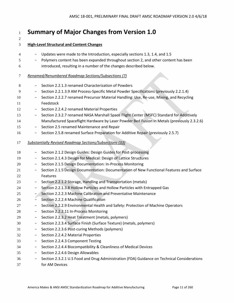
Summary of Major Changes from Version 1.0 1
2
High-Level Structural and Content Changes 3
Updates were made to the Introduction, especially sections 1.3, 1.4, and 1.5 4
Polymers content has been expanded throughout section 2, and other content has been 5
introduced, resulting in a number of the changes described below. 6
Renamed/Renumbered Roadmap Sections/Subsections (7) 7
Section 2.2.1.3 renamed Characterization of Powders 8
Section 2.2.1.3.9 AM Process-Specific Metal Powder Specifications (previously 2.2.1.4) 9
Section 2.2.2.7 renamed Precursor Material Handling: Use, Re-use, Mixing, and Recycling 10
Feedstock 11
Section 2.2.4.2 renamed Material Properties 12
Section 2.3.2.7 renamed NASA Marshall Space Flight Center (MSFC) Standard for Additively 13
Manufactured Spaceflight Hardware by Laser Powder Bed Fusion in Metals (previously 2.3.2.6) 14
Section 2.5 renamed Maintenance and Repair 15
Section 2.5.8 renamed Surface Preparation for Additive Repair (previously 2.5.7) 16
Substantially Revised Roadmap Sections/Subsections (33) 17
Section 2.1.2 Design Guides: Design Guides for Post-processing 18
Section 2.1.4.3 Design for Medical: Design of Lattice Structures 19
Section 2.1.5 Design Documentation: In-Process Monitoring 20
Section 2.1.5 Design Documentation: Documentation of New Functional Features and Surface 21
Features 22
Section 2.2.1.2 Storage, Handling and Transportation (metals) 23
Section 2.2.1.3.8 Hollow Particles and Hollow Particles with Entrapped Gas 24
Section 2.2.2.3 Machine Calibration and Preventative Maintenance 25
Section 2.2.2.4 Machine Qualification 26
Section 2.2.2.9 Environmental Health and Safety: Protection of Machine Operators 27
Section 2.2.2.11 In-Process Monitoring 28
Section 2.2.3.2 Heat Treatment (metals, polymers) 29
Section 2.2.3.4 Surface Finish (Surface Texture) (metals, polymers) 30
Section 2.2.3.6 Post-curing Methods (polymers) 31
Section 2.2.4.2 Material Properties 32
Section 2.2.4.3 Component Testing 33
Section 2.2.4.4 Biocompatibility & Cleanliness of Medical Devices 34
Section 2.2.4.6 Design Allowables 35
Section 2.3.2.1 U.S Food and Drug Administration (FDA) Guidance on Technical Considerations 36
for AM Devices 37
AMSC 18-001, PRELIMINARY FINAL DRAFT AMSC ROADMAP VERSION 2.0 4/6/18
America Makes & ANSI AMSC Standardization Roadmap for Additive Manufacturing Page 12 of 260
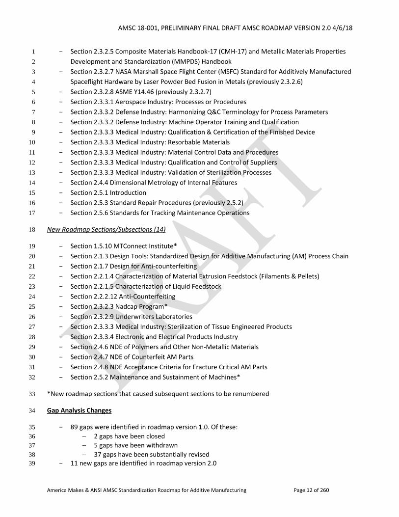
Section 2.3.2.5 Composite Materials Handbook-17 (CMH-17) and Metallic Materials Properties 1
Development and Standardization (MMPDS) Handbook 2
Section 2.3.2.7 NASA Marshall Space Flight Center (MSFC) Standard for Additively Manufactured 3
Spaceflight Hardware by Laser Powder Bed Fusion in Metals (previously 2.3.2.6) 4
Section 2.3.2.8 ASME Y14.46 (previously 2.3.2.7) 5
Section 2.3.3.1 Aerospace Industry: Processes or Procedures 6
Section 2.3.3.2 Defense Industry: Harmonizing Q&C Terminology for Process Parameters 7
Section 2.3.3.2 Defense Industry: Machine Operator Training and Qualification 8
Section 2.3.3.3 Medical Industry: Qualification & Certification of the Finished Device 9
Section 2.3.3.3 Medical Industry: Resorbable Materials 10
Section 2.3.3.3 Medical Industry: Material Control Data and Procedures 11
Section 2.3.3.3 Medical Industry: Qualification and Control of Suppliers 12
Section 2.3.3.3 Medical Industry: Validation of Sterilization Processes 13
Section 2.4.4 Dimensional Metrology of Internal Features 14
Section 2.5.1 Introduction 15
Section 2.5.3 Standard Repair Procedures (previously 2.5.2) 16
Section 2.5.6 Standards for Tracking Maintenance Operations 17
New Roadmap Sections/Subsections (14) 18
Section 1.5.10 MTConnect Institute* 19
Section 2.1.3 Design Tools: Standardized Design for Additive Manufacturing (AM) Process Chain 20
Section 2.1.7 Design for Anti-counterfeiting 21
Section 2.2.1.4 Characterization of Material Extrusion Feedstock (Filaments & Pellets) 22
Section 2.2.1.5 Characterization of Liquid Feedstock 23
Section 2.2.2.12 Anti-Counterfeiting 24
Section 2.3.2.3 Nadcap Program* 25
Section 2.3.2.9 Underwriters Laboratories 26
Section 2.3.3.3 Medical Industry: Sterilization of Tissue Engineered Products 27
Section 2.3.3.4 Electronic and Electrical Products Industry 28
Section 2.4.6 NDE of Polymers and Other Non-Metallic Materials 29
Section 2.4.7 NDE of Counterfeit AM Parts 30
Section 2.4.8 NDE Acceptance Criteria for Fracture Critical AM Parts 31
Section 2.5.2 Maintenance and Sustainment of Machines* 32
*New roadmap sections that caused subsequent sections to be renumbered 33
Gap Analysis Changes 34
89 gaps were identified in roadmap version 1.0. Of these: 35
2 gaps have been closed 36
5 gaps have been withdrawn 37
37 gaps have been substantially revised 38
11 new gaps are identified in roadmap version 2.0 39
AMSC 18-001, PRELIMINARY FINAL DRAFT AMSC ROADMAP VERSION 2.0 4/6/18
America Makes & ANSI AMSC Standardization Roadmap for Additive Manufacturing Page 13 of 260
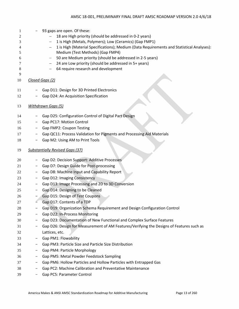
93 gaps are open. Of these: 1
18 are High priority (should be addressed in 0-2 years) 2
1 is High (Metals, Polymers); Low (Ceramics) (Gap FMP1) 3
1 is High (Material Specifications); Medium (Data Requirements and Statistical Analyses): 4
Medium (Test Methods) (Gap FMP4) 5
50 are Medium priority (should be addressed in 2-5 years) 6
24 are Low priority (should be addressed in 5+ years) 7
64 require research and development 8
9
Closed Gaps (2) 10
Gap D11: Design for 3D Printed Electronics 11
Gap D24: An Acquisition Specification 12
Withdrawn Gaps (5) 13
Gap D25: Configuration Control of Digital Part Design 14
Gap PC17: Motion Control 15
Gap FMP2: Coupon Testing 16
Gap QC11: Process Validation for Pigments and Processing Aid Materials 17
Gap M2: Using AM to Print Tools 18
Substantially Revised Gaps (37) 19
Gap D2: Decision Support: Additive Processes 20
Gap D7: Design Guide for Post-processing 21
Gap D8: Machine Input and Capability Report 22
Gap D12: Imaging Consistency 23
Gap D13: Image Processing and 2D to 3D Conversion 24
Gap D14: Designing to be Cleaned 25
Gap D15: Design of Test Coupons 26
Gap D17: Contents of a TDP 27
Gap D19: Organization Schema Requirement and Design Configuration Control 28
Gap D22: In-Process Monitoring 29
Gap D23: Documentation of New Functional and Complex Surface Features 30
Gap D26: Design for Measurement of AM Features/Verifying the Designs of Features such as 31
Lattices, etc. 32
Gap PM1: Flowability 33
Gap PM3: Particle Size and Particle Size Distribution 34
Gap PM4: Particle Morphology 35
Gap PM5: Metal Powder Feedstock Sampling 36
Gap PM6: Hollow Particles and Hollow Particles with Entrapped Gas 37
Gap PC2: Machine Calibration and Preventative Maintenance 38
Gap PC5: Parameter Control 39
AMSC 18-001, PRELIMINARY FINAL DRAFT AMSC ROADMAP VERSION 2.0 4/6/18
America Makes & ANSI AMSC Standardization Roadmap for Additive Manufacturing Page 14 of 260
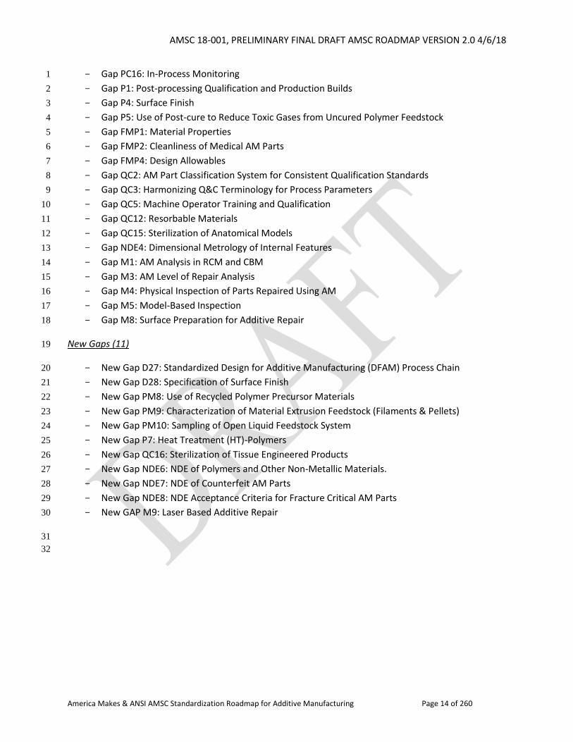
Gap PC16: In-Process Monitoring 1
Gap P1: Post-processing Qualification and Production Builds 2
Gap P4: Surface Finish 3
Gap P5: Use of Post-cure to Reduce Toxic Gases from Uncured Polymer Feedstock 4
Gap FMP1: Material Properties 5
Gap FMP2: Cleanliness of Medical AM Parts 6
Gap FMP4: Design Allowables 7
Gap QC2: AM Part Classification System for Consistent Qualification Standards 8
Gap QC3: Harmonizing Q&C Terminology for Process Parameters 9
Gap QC5: Machine Operator Training and Qualification 10
Gap QC12: Resorbable Materials 11
Gap QC15: Sterilization of Anatomical Models 12
Gap NDE4: Dimensional Metrology of Internal Features 13
Gap M1: AM Analysis in RCM and CBM 14
Gap M3: AM Level of Repair Analysis 15
Gap M4: Physical Inspection of Parts Repaired Using AM 16
Gap M5: Model-Based Inspection 17
Gap M8: Surface Preparation for Additive Repair 18
New Gaps (11) 19
New Gap D27: Standardized Design for Additive Manufacturing (DFAM) Process Chain 20
New Gap D28: Specification of Surface Finish 21
New Gap PM8: Use of Recycled Polymer Precursor Materials 22
New Gap PM9: Characterization of Material Extrusion Feedstock (Filaments & Pellets) 23
New Gap PM10: Sampling of Open Liquid Feedstock System 24
New Gap P7: Heat Treatment (HT)-Polymers 25
New Gap QC16: Sterilization of Tissue Engineered Products 26
New Gap NDE6: NDE of Polymers and Other Non-Metallic Materials. 27
New Gap NDE7: NDE of Counterfeit AM Parts 28
New Gap NDE8: NDE Acceptance Criteria for Fracture Critical AM Parts 29
New GAP M9: Laser Based Additive Repair 30
31
32
AMSC 18-001, PRELIMINARY FINAL DRAFT AMSC ROADMAP VERSION 2.0 4/6/18
America Makes & ANSI AMSC Standardization Roadmap for Additive Manufacturing Page 15 of 260
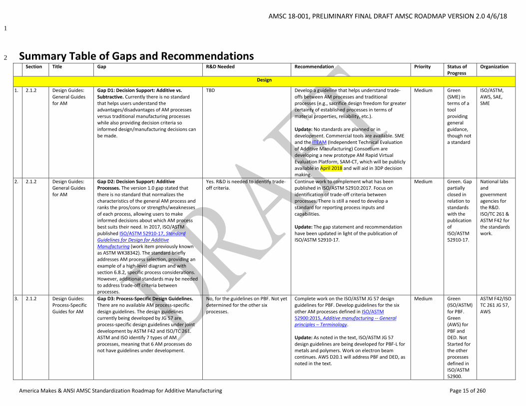
1
Summary Table of Gaps and Recommendations 2
Section Title Gap R&D Needed Recommendation Priority Status of Progress
Organization
Design
1. 2.1.2 Design Guides:
General Guides for AM
Gap D1: Decision Support: Additive vs. Subtractive. Currently there is no standard that helps users understand the advantages/disadvantages of AM processes versus traditional manufacturing processes while also providing decision criteria so informed design/manufacturing decisions can be made.
TBD Develop a guideline that helps understand trade-offs between AM processes and traditional processes (e.g., sacrifice design freedom for greater certainty of established processes in terms of material properties, reliability, etc.). Update: No standards are planned or in development. Commercial tools are available. SME and the ITEAM (Independent Technical Evaluation of Additive Manufacturing) Consortium are developing a new prototype AM Rapid Virtual Evaluation Platform, SAM-CT, which will be publicly available in April 2018 and will aid in 3DP decision making.
Medium Green (SME) in terms of a tool providing general guidance, though not a standard
ISO/ASTM, AWS, SAE, SME
2. 2.1.2 Design Guides: General Guides for AM
Gap D2: Decision Support: Additive Processes. The version 1.0 gap stated that there is no standard that normalizes the characteristics of the general AM process and ranks the pros/cons or strengths/weaknesses of each process, allowing users to make informed decisions about which AM process best suits their need. In 2017, ISO/ASTM published ISO/ASTM 52910-17, Standard Guidelines for Design for Additive Manufacturing (work item previously known as ASTM WK38342). The standard briefly addresses AM process selection, providing an example of a high-level diagram and with section 6.8.2, specific process considerations. However, additional standards may be needed to address trade-off criteria between processes.
Yes. R&D is needed to identify trade-off criteria.
Continue work to complement what has been published in ISO/ASTM 52910:2017. Focus on identification of trade-off criteria between processes. There is still a need to develop a standard for reporting process inputs and capabilities. Update: The gap statement and recommendation have been updated in light of the publication of ISO/ASTM 52910-17.
Medium Green. Gap partially closed in relation to standards with the publication of ISO/ASTM 52910-17.
National labs and government agencies for the R&D. ISO/TC 261 & ASTM F42 for the standards work.
3. 2.1.2 Design Guides: Process-Specific Guides for AM
Gap D3: Process-Specific Design Guidelines. There are no available AM process-specific design guidelines. The design guidelines currently being developed by JG 57 are process-specific design guidelines under joint development by ASTM F42 and ISO/TC 261. ASTM and ISO identify 7 types of AM processes, meaning that 6 AM processes do not have guidelines under development.
No, for the guidelines on PBF. Not yet determined for the other six processes.
Complete work on the ISO/ASTM JG 57 design guidelines for PBF. Develop guidelines for the six other AM processes defined in ISO/ASTM 52900:2015, Additive manufacturing -- General principles – Terminology. Update: As noted in the text, ISO/ASTM JG 57 design guidelines are being developed for PBF-L for metals and polymers. Work on electron beam continues. AWS D20.1 will address PBF and DED, as noted in the text.
Medium Green (ISO/ASTM) for PBF. Green (AWS) for PBF and DED. Not Started for the other processes defined in ISO/ASTM 52900.
ASTM F42/ISO TC 261 JG 57, AWS
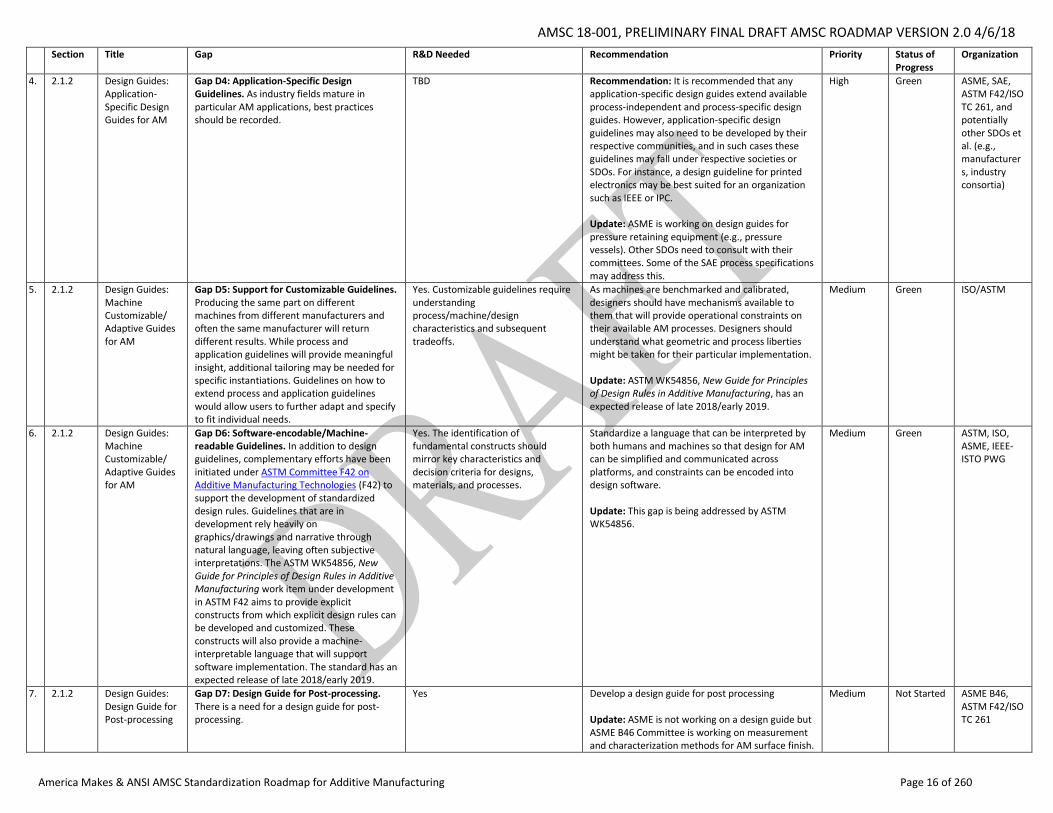
AMSC 18-001, PRELIMINARY FINAL DRAFT AMSC ROADMAP VERSION 2.0 4/6/18
America Makes & ANSI AMSC Standardization Roadmap for Additive Manufacturing Page 16 of 260
Section Title Gap R&D Needed Recommendation Priority Status of Progress
Organization
4. 2.1.2 Design Guides: Application-Specific Design Guides for AM
Gap D4: Application-Specific Design Guidelines. As industry fields mature in particular AM applications, best practices should be recorded.
TBD Recommendation: It is recommended that any application-specific design guides extend available process-independent and process-specific design guides. However, application-specific design guidelines may also need to be developed by their respective communities, and in such cases these guidelines may fall under respective societies or SDOs. For instance, a design guideline for printed electronics may be best suited for an organization such as IEEE or IPC. Update: ASME is working on design guides for pressure retaining equipment (e.g., pressure vessels). Other SDOs need to consult with their committees. Some of the SAE process specifications may address this.
High Green ASME, SAE, ASTM F42/ISO TC 261, and potentially other SDOs et al. (e.g., manufacturers, industry consortia)
5. 2.1.2 Design Guides: Machine Customizable/ Adaptive Guides for AM
Gap D5: Support for Customizable Guidelines. Producing the same part on different machines from different manufacturers and often the same manufacturer will return different results. While process and application guidelines will provide meaningful insight, additional tailoring may be needed for specific instantiations. Guidelines on how to extend process and application guidelines would allow users to further adapt and specify to fit individual needs.
Yes. Customizable guidelines require understanding process/machine/design characteristics and subsequent tradeoffs.
As machines are benchmarked and calibrated, designers should have mechanisms available to them that will provide operational constraints on their available AM processes. Designers should understand what geometric and process liberties might be taken for their particular implementation. Update: ASTM WK54856, New Guide for Principles of Design Rules in Additive Manufacturing, has an expected release of late 2018/early 2019.
Medium Green ISO/ASTM
6. 2.1.2 Design Guides: Machine Customizable/ Adaptive Guides for AM
Gap D6: Software-encodable/Machine-readable Guidelines. In addition to design guidelines, complementary efforts have been initiated under ASTM Committee F42 on Additive Manufacturing Technologies (F42) to support the development of standardized design rules. Guidelines that are in development rely heavily on graphics/drawings and narrative through natural language, leaving often subjective interpretations. The ASTM WK54856, New Guide for Principles of Design Rules in Additive Manufacturing work item under development in ASTM F42 aims to provide explicit constructs from which explicit design rules can be developed and customized. These constructs will also provide a machine-interpretable language that will support software implementation. The standard has an expected release of late 2018/early 2019.
Yes. The identification of fundamental constructs should mirror key characteristics and decision criteria for designs, materials, and processes.
Standardize a language that can be interpreted by both humans and machines so that design for AM can be simplified and communicated across platforms, and constraints can be encoded into design software. Update: This gap is being addressed by ASTM WK54856.
Medium Green ASTM, ISO, ASME, IEEE-ISTO PWG
7. 2.1.2 Design Guides: Design Guide for Post-processing
Gap D7: Design Guide for Post-processing. There is a need for a design guide for post-processing.
Yes Develop a design guide for post processing Update: ASME is not working on a design guide but ASME B46 Committee is working on measurement and characterization methods for AM surface finish.
Medium Not Started ASME B46, ASTM F42/ISO TC 261
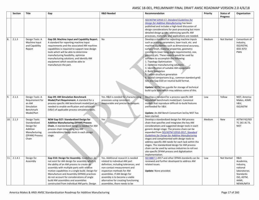
AMSC 18-001, PRELIMINARY FINAL DRAFT AMSC ROADMAP VERSION 2.0 4/6/18
America Makes & ANSI AMSC Standardization Roadmap for Additive Manufacturing Page 17 of 260
Section Title Gap R&D Needed Recommendation Priority Status of Progress
Organization
ISO/ASTM 52910-17, Standard Guidelines for Design for Additive Manufacturing has been published and includes a high-level discussion of design considerations for post-processing but more detailed design guides addressing specific AM processes, materials, and applications are needed.
8. 2.1.3 Design Tools: A Machine Input and Capability Report
Gap D8: Machine Input and Capability Report. A standard for reporting machine input requirements and the associated AM machine capabilities is required to support new design tools which will be able to determine manufacturing feasibility, optimize manufacturing solutions, and identify AM equipment which would be able to manufacture the part.
No Develop a standard for reporting machine inputs such as printing parameters, laser track, etc. and machine capabilities such as dimensional accuracy, surface finish, material properties, geometry constraints (over hang angle requirements), size, porosity, etc. These reports would be used by software to accomplish the following: 1. Topology Optimization 2. Optimize manufacturing solutions 3. Identification of suitable AM equipment 4. Build Simulation 5. Lattice structure generation 6. Spatial comparisons (e.g., common standard grid) See also Gap D20 on neutral build format. Update: ASTM has a guide for storage of technical build cycle data which may address some of this.
Medium Not Started Consortium of industry, ISO/ASTM, IEEE-ISTO PWG
9. 2.1.3 Design Tools: A Requirement for an AM Simulation Benchmark Model/Part
Gap D9: AM Simulation Benchmark Model/Part Requirement. A standard for a process-specific AM benchmark model/part is needed to enable verification and validation (V&V) of applicable process simulation tools.
Yes. R&D is needed for characterizing processes using consistent, measurable and precise techniques.
Develop a standard for a process-specific AM simulation benchmark model/part. Canonical models that reproduce difficult-to-build features are needed for V&V. Update: An AM Bench Consortium led by NIST has been started.
Low Yellow NIST, America Makes, ASME V&V, ISO/ASTM
10. 2.1.3 Design Tools: Standardized Design for Additive Manufacturing (DFAM) Process Chain
NEW Gap D27: Standardized Design for Additive Manufacturing (DFAM) Process Chain. A standardized design is needed for AM process chain integrating key AM considerations/design tools in each design stage.
Yes Develop a standardized design for AM process chain that specifies and integrates the key AM considerations and suggested design tools in each generic design stage. The process chain can be expanded from ISO/ASTM 52910-2017, Standard Guidelines for Design for Additive Manufacturing stages and complimented with design tools to address specific AM needs for each task within the stages. The standardized design for AM process chain can be used by various industries to roll out site-specific DFAM process and digitalization implementation.
Medium New ASTM F42/ISO TC 261 JG 73, NIST
11. 2.1.4.1 Design for Assembly
Gap D10: Design for Assembly. Guidelines do not exist for AM design for assembly which is the ability of an AM process to create an assembly with multiple parts with relative motion capabilities in a single build. Design for Manufacture and Assembly (DFMA) practices do not account for considerations of single build AM assemblies and assemblies constructed from individual AM parts. Design
Yes. Additional research is needed related to individual AM part definition, including tolerances, and non-contact measurement and inspection methods for AM assemblies. If AM design for assembly is to become a viable alternative for creating functioning assemblies, there needs to be
ISO 8887-1:2017 and other DFMA standards can be reviewed and further developed to address AM related issues. Update: None provided.
Low Not Started R&D: Academia, industry, national laboratories. Standards: ISO, ASTM, AAMI, NEMA/MITA
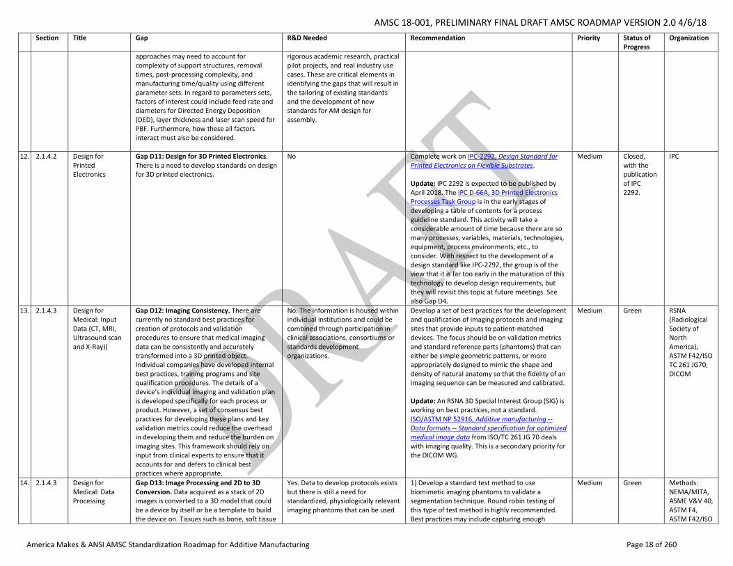
AMSC 18-001, PRELIMINARY FINAL DRAFT AMSC ROADMAP VERSION 2.0 4/6/18
America Makes & ANSI AMSC Standardization Roadmap for Additive Manufacturing Page 18 of 260
Section Title Gap R&D Needed Recommendation Priority Status of Progress
Organization
approaches may need to account for complexity of support structures, removal times, post-processing complexity, and manufacturing time/quality using different parameter sets. In regard to parameters sets, factors of interest could include feed rate and diameters for Directed Energy Deposition (DED), layer thickness and laser scan speed for PBF. Furthermore, how these all factors interact must also be considered.
rigorous academic research, practical pilot projects, and real industry use cases. These are critical elements in identifying the gaps that will result in the tailoring of existing standards and the development of new standards for AM design for assembly.
12. 2.1.4.2 Design for Printed Electronics
Gap D11: Design for 3D Printed Electronics. There is a need to develop standards on design for 3D printed electronics.
No Complete work on IPC-2292, Design Standard for Printed Electronics on Flexible Substrates. Update: IPC 2292 is expected to be published by April 2018. The IPC D-66A, 3D Printed Electronics Processes Task Group is in the early stages of developing a table of contents for a process guideline standard. This activity will take a considerable amount of time because there are so many processes, variables, materials, technologies, equipment, process environments, etc., to consider. With respect to the development of a design standard like IPC-2292, the group is of the view that it is far too early in the maturation of this technology to develop design requirements, but they will revisit this topic at future meetings. See also Gap D4.
Medium Closed, with the publication of IPC 2292.
IPC
13. 2.1.4.3 Design for Medical: Input Data (CT, MRI, Ultrasound scan and X-Ray))
Gap D12: Imaging Consistency. There are currently no standard best practices for creation of protocols and validation procedures to ensure that medical imaging data can be consistently and accurately transformed into a 3D printed object. Individual companies have developed internal best practices, training programs and site qualification procedures. The details of a device’s individual imaging and validation plan is developed specifically for each process or product. However, a set of consensus best practices for developing these plans and key validation metrics could reduce the overhead in developing them and reduce the burden on imaging sites. This framework should rely on input from clinical experts to ensure that it accounts for and defers to clinical best practices where appropriate.
No. The information is housed within individual institutions and could be combined through participation in clinical associations, consortiums or standards development organizations.
Develop a set of best practices for the development and qualification of imaging protocols and imaging sites that provide inputs to patient-matched devices. The focus should be on validation metrics and standard reference parts (phantoms) that can either be simple geometric patterns, or more appropriately designed to mimic the shape and density of natural anatomy so that the fidelity of an imaging sequence can be measured and calibrated. Update: An RSNA 3D Special Interest Group (SIG) is working on best practices, not a standard. ISO/ASTM NP 52916, Additive manufacturing -- Data formats -- Standard specification for optimized medical image data from ISO/TC 261 JG 70 deals with imaging quality. This is a secondary priority for the DICOM WG.
Medium Green RSNA (Radiological Society of North America), ASTM F42/ISO TC 261 JG70, DICOM
14. 2.1.4.3 Design for Medical: Data Processing
Gap D13: Image Processing and 2D to 3D Conversion. Data acquired as a stack of 2D images is converted to a 3D model that could be a device by itself or be a template to build the device on. Tissues such as bone, soft tissue
Yes. Data to develop protocols exists but there is still a need for standardized, physiologically relevant imaging phantoms that can be used
1) Develop a standard test method to use biomimetic imaging phantoms to validate a segmentation technique. Round robin testing of this type of test method is highly recommended. Best practices may include capturing enough
Medium Green Methods: NEMA/MITA, ASME V&V 40, ASTM F4, ASTM F42/ISO
AMSC 18-001, PRELIMINARY FINAL DRAFT AMSC ROADMAP VERSION 2.0 4/6/18
America Makes & ANSI AMSC Standardization Roadmap for Additive Manufacturing Page 19 of 260
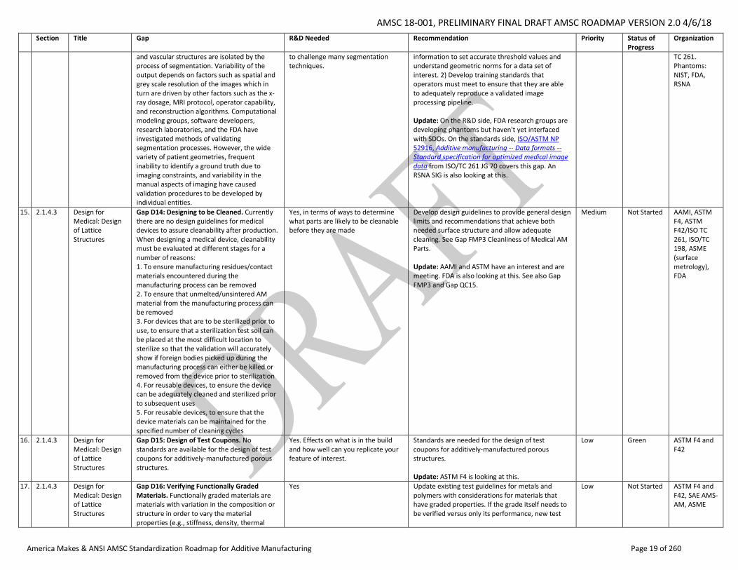
Section Title Gap R&D Needed Recommendation Priority Status of Progress
Organization
and vascular structures are isolated by the process of segmentation. Variability of the output depends on factors such as spatial and grey scale resolution of the images which in turn are driven by other factors such as the x-ray dosage, MRI protocol, operator capability, and reconstruction algorithms. Computational modeling groups, software developers, research laboratories, and the FDA have investigated methods of validating segmentation processes. However, the wide variety of patient geometries, frequent inability to identify a ground truth due to imaging constraints, and variability in the manual aspects of imaging have caused validation procedures to be developed by individual entities.
to challenge many segmentation techniques.
information to set accurate threshold values and understand geometric norms for a data set of interest. 2) Develop training standards that operators must meet to ensure that they are able to adequately reproduce a validated image processing pipeline. Update: On the R&D side, FDA research groups are developing phantoms but haven't yet interfaced with SDOs. On the standards side, ISO/ASTM NP 52916, Additive manufacturing -- Data formats -- Standard specification for optimized medical image data from ISO/TC 261 JG 70 covers this gap. An RSNA SIG is also looking at this.
TC 261. Phantoms: NIST, FDA, RSNA
15. 2.1.4.3 Design for Medical: Design of Lattice Structures
Gap D14: Designing to be Cleaned. Currently there are no design guidelines for medical devices to assure cleanability after production. When designing a medical device, cleanability must be evaluated at different stages for a number of reasons: 1. To ensure manufacturing residues/contact materials encountered during the manufacturing process can be removed 2. To ensure that unmelted/unsintered AM material from the manufacturing process can be removed 3. For devices that are to be sterilized prior to use, to ensure that a sterilization test soil can be placed at the most difficult location to sterilize so that the validation will accurately show if foreign bodies picked up during the manufacturing process can either be killed or removed from the device prior to sterilization 4. For reusable devices, to ensure the device can be adequately cleaned and sterilized prior to subsequent uses 5. For reusable devices, to ensure that the device materials can be maintained for the specified number of cleaning cycles
Yes, in terms of ways to determine what parts are likely to be cleanable before they are made
Develop design guidelines to provide general design limits and recommendations that achieve both needed surface structure and allow adequate cleaning. See Gap FMP3 Cleanliness of Medical AM Parts. Update: AAMI and ASTM have an interest and are meeting. FDA is also looking at this. See also Gap FMP3 and Gap QC15.
Medium Not Started AAMI, ASTM F4, ASTM F42/ISO TC 261, ISO/TC 198, ASME (surface metrology), FDA
16. 2.1.4.3 Design for Medical: Design of Lattice Structures
Gap D15: Design of Test Coupons. No standards are available for the design of test coupons for additively-manufactured porous structures.
Yes. Effects on what is in the build and how well can you replicate your feature of interest.
Standards are needed for the design of test coupons for additively-manufactured porous structures. Update: ASTM F4 is looking at this.
Low Green ASTM F4 and F42
17. 2.1.4.3 Design for Medical: Design of Lattice Structures
Gap D16: Verifying Functionally Graded Materials. Functionally graded materials are materials with variation in the composition or structure in order to vary the material properties (e.g., stiffness, density, thermal
Yes Update existing test guidelines for metals and polymers with considerations for materials that have graded properties. If the grade itself needs to be verified versus only its performance, new test
Low Not Started ASTM F4 and F42, SAE AMS-AM, ASME
AMSC 18-001, PRELIMINARY FINAL DRAFT AMSC ROADMAP VERSION 2.0 4/6/18
America Makes & ANSI AMSC Standardization Roadmap for Additive Manufacturing Page 20 of 260
Section Title Gap R&D Needed Recommendation Priority Status of Progress
Organization
conductivity, etc.). Standard methods of specifying and verifying functionally graded materials currently do not exist. Furthermore, there are no guidelines on considerations when validating their performance.
methods may be needed. This is a broad topic however and depends on what is being evaluated. Update: No information is available regarding work underway to action this from the R&D or standardization perspective.
18. 2.1.5 Design Documentation: Technical Data Package (TDP) Content
Gap D17: Contents of a TDP. The contents of a TDP that is sufficiently complete such that it could be provided to a vendor and result in components that are identical in physical and performance characteristics has not been defined.
Yes Develop a standard (or revise MIL-STD-31000A, Technical Data Packages) to describe all required portions of a TDP and adopt them into a formal standard. The standard should address at a minimum: • Performance/functional requirements (form, fit assembly) • Qualification requirements • Definition of “as-designed” part, versus “as-printed” part, versus “finished” part • Post-processing requirements (including finishing, removal of parts from AM machine such as separation from build plate) • Applicable AM process • Tailorable and non-tailorable build parameters • Cybersecurity requirements (if necessary) • Long term archival and retrieval process (including acquisition) Update: NIST has been involved in developing a number of component standards with various SDOs. DoD is pushing for a standard that defines the contents of a TDP to cover DoD products. DoD is in the process of updating 31000A2 revision B. ASME Y14.47, Model Organization Schema Practices, is based on Appendix B of MIL-STD-31000A. It should be available by the second quarter of 2018. DoD representatives are involved in the development of Y14.47. SAE G-33 on configuration management is not working on this gap at this time. There is a joint WG for digital product definition and data management under ASTM/ISO (JG 73).
High Green ASME Y14.47, ASTM F2/ISO TC 261, DoD AFRL, NIST, SAE G-33
19. 2.1.5 Design Documentation: New Dimensioning and Tolerancing Requirements
Gap D18: New Dimensioning and Tolerancing Requirements. Although ASME Y14.41, Digital Product Definition Data Practices does provide some capability in addressing some of the challenges in documenting AM designs, significant gaps still remain. ASME Y14.46 will address these gaps.
No Complete work on ASME Y14.46. See also Gap D26 on measurement of AM features/verifying the designs of features such as lattices, etc. Update: ASME Y14.46-2017, Product Definition for Additive Manufacturing [Draft Standard for Trial Use] has been published and items within the standard related to this gap are still under development pending final approval. ASME Y14.48 on Universal Direction may also be relevant but that will not be available for another year or two. NIST provides a vice chair of the Y14 subcommittee 46.
High Green ASME Y14.46, ASME Y14.48, NIST
AMSC 18-001, PRELIMINARY FINAL DRAFT AMSC ROADMAP VERSION 2.0 4/6/18
America Makes & ANSI AMSC Standardization Roadmap for Additive Manufacturing Page 21 of 260
Section Title Gap R&D Needed Recommendation Priority Status of Progress
Organization
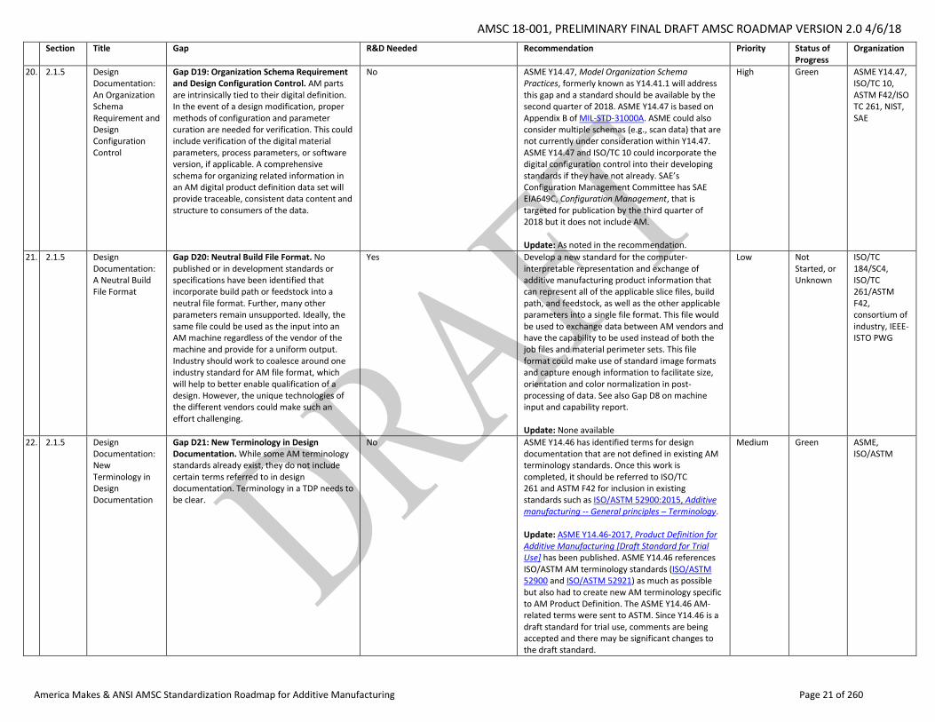
20. 2.1.5 Design Documentation: An Organization Schema Requirement and Design Configuration Control
Gap D19: Organization Schema Requirement and Design Configuration Control. AM parts are intrinsically tied to their digital definition. In the event of a design modification, proper methods of configuration and parameter curation are needed for verification. This could include verification of the digital material parameters, process parameters, or software version, if applicable. A comprehensive schema for organizing related information in an AM digital product definition data set will provide traceable, consistent data content and structure to consumers of the data.
No ASME Y14.47, Model Organization Schema Practices, formerly known as Y14.41.1 will address this gap and a standard should be available by the second quarter of 2018. ASME Y14.47 is based on Appendix B of MIL-STD-31000A. ASME could also consider multiple schemas (e.g., scan data) that are not currently under consideration within Y14.47. ASME Y14.47 and ISO/TC 10 could incorporate the digital configuration control into their developing standards if they have not already. SAE’s Configuration Management Committee has SAE EIA649C, Configuration Management, that is targeted for publication by the third quarter of 2018 but it does not include AM. Update: As noted in the recommendation.
High Green ASME Y14.47, ISO/TC 10, ASTM F42/ISO TC 261, NIST, SAE
21. 2.1.5 Design Documentation: A Neutral Build File Format
Gap D20: Neutral Build File Format. No published or in development standards or specifications have been identified that incorporate build path or feedstock into a neutral file format. Further, many other parameters remain unsupported. Ideally, the same file could be used as the input into an AM machine regardless of the vendor of the machine and provide for a uniform output. Industry should work to coalesce around one industry standard for AM file format, which will help to better enable qualification of a design. However, the unique technologies of the different vendors could make such an effort challenging.
Yes Develop a new standard for the computer-interpretable representation and exchange of additive manufacturing product information that can represent all of the applicable slice files, build path, and feedstock, as well as the other applicable parameters into a single file format. This file would be used to exchange data between AM vendors and have the capability to be used instead of both the job files and material perimeter sets. This file format could make use of standard image formats and capture enough information to facilitate size, orientation and color normalization in post-processing of data. See also Gap D8 on machine input and capability report. Update: None available
Low Not Started, or Unknown
ISO/TC 184/SC4, ISO/TC 261/ASTM F42, consortium of industry, IEEE-ISTO PWG
22. 2.1.5 Design Documentation: New Terminology in Design Documentation
Gap D21: New Terminology in Design Documentation. While some AM terminology standards already exist, they do not include certain terms referred to in design documentation. Terminology in a TDP needs to be clear.
No ASME Y14.46 has identified terms for design documentation that are not defined in existing AM terminology standards. Once this work is completed, it should be referred to ISO/TC 261 and ASTM F42 for inclusion in existing standards such as ISO/ASTM 52900:2015, Additive manufacturing -- General principles – Terminology. Update: ASME Y14.46-2017, Product Definition for Additive Manufacturing [Draft Standard for Trial Use] has been published. ASME Y14.46 references ISO/ASTM AM terminology standards (ISO/ASTM 52900 and ISO/ASTM 52921) as much as possible but also had to create new AM terminology specific to AM Product Definition. The ASME Y14.46 AM-related terms were sent to ASTM. Since Y14.46 is a draft standard for trial use, comments are being accepted and there may be significant changes to the draft standard.
Medium Green ASME, ISO/ASTM
AMSC 18-001, PRELIMINARY FINAL DRAFT AMSC ROADMAP VERSION 2.0 4/6/18
America Makes & ANSI AMSC Standardization Roadmap for Additive Manufacturing Page 22 of 260
Section Title Gap R&D Needed Recommendation Priority Status of Progress
Organization
23. 2.1.5 Design Documentation: In-Process Monitoring
Gap D22: In-Process Monitoring. There is a lack of standards for validated physics- and properties-based predictive models for AM that incorporate geometric accuracy, material properties, defects, surface characteristics, residual stress, microstructure properties, and other characteristics (NIST, 2013). No standardized data models or documentation have been identified for in-process monitoring and analytics. Given the current state of the technology, this is not surprising.
Yes. R&D is needed to understand what in-process monitoring data is needed for verification and validation of the part. Research efforts have been undertaken that are devoted to the development of predictive computational models and simulations to understand the dynamics and complexity of heat and phase transformations. Although computational models and simulations are promising tools to understand the physics of the process, lack of quantitative representation of their prediction accuracy hinders further application in process control and optimization. Due to this reason, it is very challenging to select suitable models for the intended purpose. Therefore, it is important to study and investigate the degree of accuracy and uncertainty associated with AM models.
Develop standards for predictive computational modeling and simulation tools that link measured in-process monitoring data with product properties, quality, and consistency, as an important aspect of innovative structural design (NIST, 2013). See also Gap PC16 on in-process monitoring to obtain a layer-by-layer (3D) file or quality record showing the as-built part is defect-free or contains no critical flaws, or exhibits an in-family (nominal) response when interrogated during the build. Update: Office of Naval Research (ONR) is also researching this through their Quality Made program. NIST is developing a publically available schema for metals that may apply.
Medium Green ASTM F42, ASME, IEEE-ISTO PWG
24. 2.1.5 Design Documentation: Documentation of New Functional Features and Surface Features
Gap D23: Documentation of New Functional and Complex Surface Features. There is a need for a specification on design documentation for intentionally introducing new bulk or surface geometries which can be created through AM.
No ASME Y14.46 should consider an annex describing a method to document functional and complex geometric features. Update: As noted in the recommendation. ASME Y14.46-2017, Product Definition for Additive Manufacturing [Draft Standard for Trial Use] has been published.
Low Green ASME
25. 2.1.5 Design Documentation: Documentation of New Functional Features and Surface Features
NEW Gap D28: Specification of Surface Finish. There is a need for a specification on desired surface finishes of AM parts that can later be measured and validated against. Current surface finish metrics, such as Ra, do not adequately specify surface finish requirements.
Yes ASME should continue its work to develop ASME B46.1-2009, Surface Texture (Surface Roughness, Waviness, and Lay), to address specification requirements of AM surface finishes.
Medium New ASME
26. 2.1.5 Design Documentation: An Acquisition Specification
Gap D24: An Acquisition Specification. A specification is needed to procure AM parts from third parties.
No ASTM should complete work on WK51282, New Guide for Additive Manufacturing, General Principles, Requirements for Purchased AM Parts. Update: ISO/ASTM 52901, Additive manufacturing General Principles - Requirements for Purchased AM Parts was published in 2017. WK51282 was the earlier ASTM work item.
Medium Closed ISO/ASTM
27. 2.1.6 Design Verification and Validation
Gap D26: Design for Measurement of AM Features/Verifying the Designs of Features such as Lattices, etc. As noted in Gap D18, working groups are currently developing methods to standardize the geometric
Yes, investigation of high resolution radiographic and ultrasonic methods and the maximum achievable resolution and accuracy for GD&T of complex AM designs.
As GD&T standards continue to develop, perform parallel investigations of validation methods to ensure V&V is possible. See also Gap NDE4, Dimensional Metrology of Internal Features.
Medium Not Started ISO/TC 261/ASTM F42, ASTM E07.01, ASTM E07.02, ASME
AMSC 18-001, PRELIMINARY FINAL DRAFT AMSC ROADMAP VERSION 2.0 4/6/18
America Makes & ANSI AMSC Standardization Roadmap for Additive Manufacturing Page 23 of 260
Section Title Gap R&D Needed Recommendation Priority Status of Progress
Organization
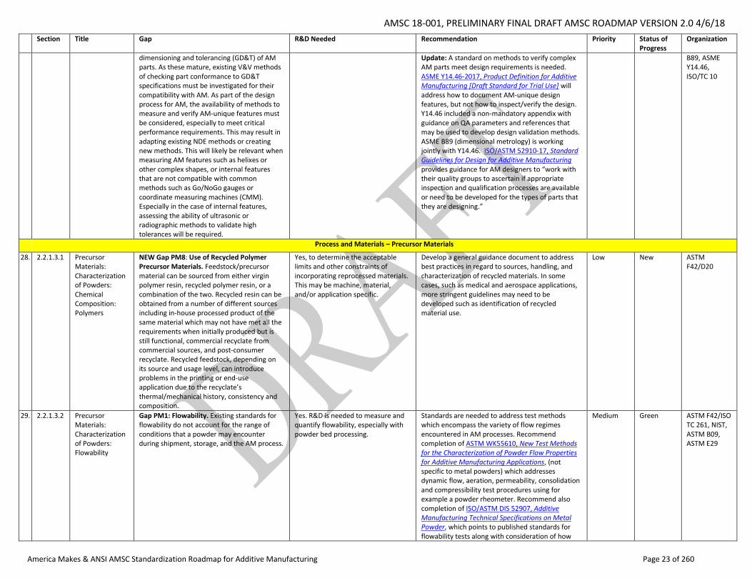
dimensioning and tolerancing (GD&T) of AM parts. As these mature, existing V&V methods of checking part conformance to GD&T specifications must be investigated for their compatibility with AM. As part of the design process for AM, the availability of methods to measure and verify AM-unique features must be considered, especially to meet critical performance requirements. This may result in adapting existing NDE methods or creating new methods. This will likely be relevant when measuring AM features such as helixes or other complex shapes, or internal features that are not compatible with common methods such as Go/NoGo gauges or coordinate measuring machines (CMM). Especially in the case of internal features, assessing the ability of ultrasonic or radiographic methods to validate high tolerances will be required.
Update: A standard on methods to verify complex AM parts meet design requirements is needed. ASME Y14.46-2017, Product Definition for Additive Manufacturing [Draft Standard for Trial Use] will address how to document AM-unique design features, but not how to inspect/verify the design. Y14.46 included a non-mandatory appendix with guidance on QA parameters and references that may be used to develop design validation methods. ASME B89 (dimensional metrology) is working jointly with Y14.46. ISO/ASTM 52910-17, Standard Guidelines for Design for Additive Manufacturing provides guidance for AM designers to “work with their quality groups to ascertain if appropriate inspection and qualification processes are available or need to be developed for the types of parts that they are designing.”
B89, ASME Y14.46, ISO/TC 10
Process and Materials – Precursor Materials
28. 2.2.1.3.1 Precursor Materials: Characterization of Powders: Chemical Composition: Polymers
NEW Gap PM8: Use of Recycled Polymer Precursor Materials. Feedstock/precursor material can be sourced from either virgin polymer resin, recycled polymer resin, or a combination of the two. Recycled resin can be obtained from a number of different sources including in-house processed product of the same material which may not have met all the requirements when initially produced but is still functional, commercial recyclate from commercial sources, and post-consumer recyclate. Recycled feedstock, depending on its source and usage level, can introduce problems in the printing or end-use application due to the recyclate’s thermal/mechanical history, consistency and composition.
Yes, to determine the acceptable limits and other constraints of incorporating reprocessed materials. This may be machine, material, and/or application specific.
Develop a general guidance document to address best practices in regard to sources, handling, and characterization of recycled materials. In some cases, such as medical and aerospace applications, more stringent guidelines may need to be developed such as identification of recycled material use.
Low New ASTM F42/D20
29. 2.2.1.3.2 Precursor Materials: Characterization of Powders: Flowability
Gap PM1: Flowability. Existing standards for flowability do not account for the range of conditions that a powder may encounter during shipment, storage, and the AM process.
Yes. R&D is needed to measure and quantify flowability, especially with powder bed processing.
Standards are needed to address test methods which encompass the variety of flow regimes encountered in AM processes. Recommend completion of ASTM WK55610, New Test Methods for the Characterization of Powder Flow Properties for Additive Manufacturing Applications, (not specific to metal powders) which addresses dynamic flow, aeration, permeability, consolidation and compressibility test procedures using for example a powder rheometer. Recommend also completion of ISO/ASTM DIS 52907, Additive Manufacturing Technical Specifications on Metal Powder, which points to published standards for flowability tests along with consideration of how
Medium Green ASTM F42/ISO TC 261, NIST, ASTM B09, ASTM E29
AMSC 18-001, PRELIMINARY FINAL DRAFT AMSC ROADMAP VERSION 2.0 4/6/18
America Makes & ANSI AMSC Standardization Roadmap for Additive Manufacturing Page 24 of 260
Section Title Gap R&D Needed Recommendation Priority Status of Progress
Organization
the state of the powder would affect the flowability measurement. See also Gap PC12 on precursor material flow monitoring. Update: As noted in the text, ASTM WK55610 and ISO/ASTM DIS 52907 are in development. Completion of those work items may partially but not fully address the gap.
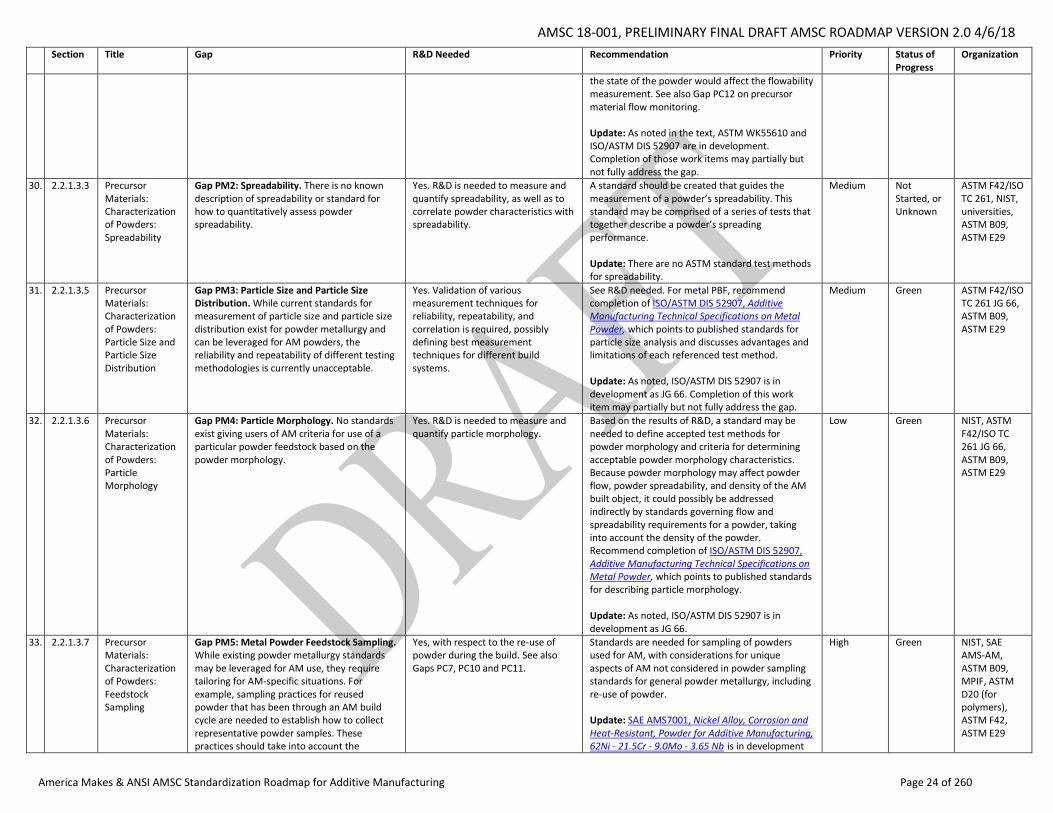
30. 2.2.1.3.3 Precursor Materials: Characterization of Powders: Spreadability
Gap PM2: Spreadability. There is no known description of spreadability or standard for how to quantitatively assess powder spreadability.
Yes. R&D is needed to measure and quantify spreadability, as well as to correlate powder characteristics with spreadability.
A standard should be created that guides the measurement of a powder’s spreadability. This standard may be comprised of a series of tests that together describe a powder’s spreading performance. Update: There are no ASTM standard test methods for spreadability.
Medium Not Started, or Unknown
ASTM F42/ISO TC 261, NIST, universities, ASTM B09, ASTM E29
31. 2.2.1.3.5 Precursor Materials: Characterization of Powders: Particle Size and Particle Size Distribution
Gap PM3: Particle Size and Particle Size Distribution. While current standards for measurement of particle size and particle size distribution exist for powder metallurgy and can be leveraged for AM powders, the reliability and repeatability of different testing methodologies is currently unacceptable.
Yes. Validation of various measurement techniques for reliability, repeatability, and correlation is required, possibly defining best measurement techniques for different build systems.
See R&D needed. For metal PBF, recommend completion of ISO/ASTM DIS 52907, Additive Manufacturing Technical Specifications on Metal Powder, which points to published standards for particle size analysis and discusses advantages and limitations of each referenced test method. Update: As noted, ISO/ASTM DIS 52907 is in development as JG 66. Completion of this work item may partially but not fully address the gap.
Medium Green ASTM F42/ISO TC 261 JG 66, ASTM B09, ASTM E29
32. 2.2.1.3.6 Precursor Materials: Characterization of Powders: Particle Morphology
Gap PM4: Particle Morphology. No standards exist giving users of AM criteria for use of a particular powder feedstock based on the powder morphology.
Yes. R&D is needed to measure and quantify particle morphology.
Based on the results of R&D, a standard may be needed to define accepted test methods for powder morphology and criteria for determining acceptable powder morphology characteristics. Because powder morphology may affect powder flow, powder spreadability, and density of the AM built object, it could possibly be addressed indirectly by standards governing flow and spreadability requirements for a powder, taking into account the density of the powder. Recommend completion of ISO/ASTM DIS 52907, Additive Manufacturing Technical Specifications on Metal Powder, which points to published standards for describing particle morphology. Update: As noted, ISO/ASTM DIS 52907 is in development as JG 66.
Low Green NIST, ASTM F42/ISO TC 261 JG 66, ASTM B09, ASTM E29
33. 2.2.1.3.7 Precursor Materials: Characterization of Powders: Feedstock Sampling
Gap PM5: Metal Powder Feedstock Sampling. While existing powder metallurgy standards may be leveraged for AM use, they require tailoring for AM-specific situations. For example, sampling practices for reused powder that has been through an AM build cycle are needed to establish how to collect representative powder samples. These practices should take into account the
Yes, with respect to the re-use of powder during the build. See also Gaps PC7, PC10 and PC11.
Standards are needed for sampling of powders used for AM, with considerations for unique aspects of AM not considered in powder sampling standards for general powder metallurgy, including re-use of powder. Update: SAE AMS7001, Nickel Alloy, Corrosion and Heat-Resistant, Powder for Additive Manufacturing, 62Ni - 21.5Cr - 9.0Mo - 3.65 Nb is in development
High Green NIST, SAE AMS-AM, ASTM B09, MPIF, ASTM D20 (for polymers), ASTM F42, ASTM E29
AMSC 18-001, PRELIMINARY FINAL DRAFT AMSC ROADMAP VERSION 2.0 4/6/18
America Makes & ANSI AMSC Standardization Roadmap for Additive Manufacturing Page 25 of 260
Section Title Gap R&D Needed Recommendation Priority Status of Progress
Organization
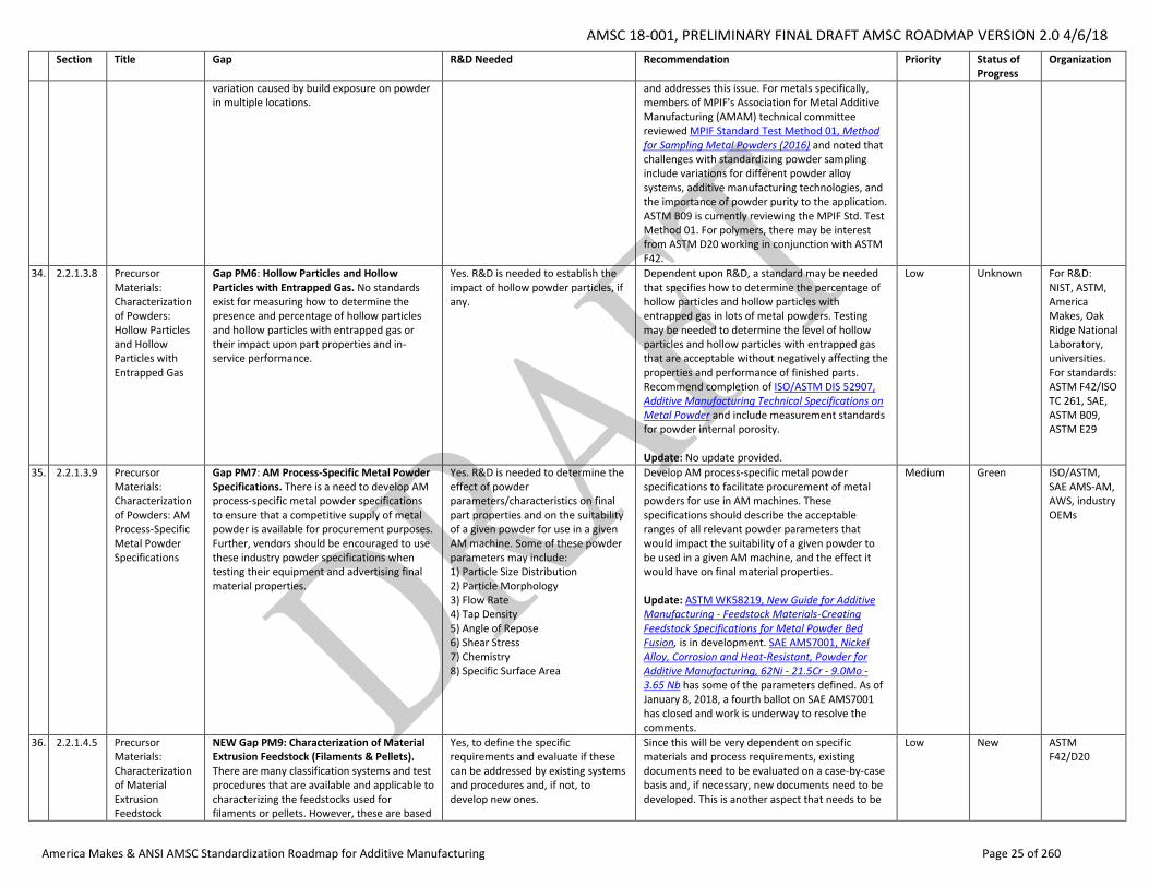
variation caused by build exposure on powder in multiple locations.
and addresses this issue. For metals specifically, members of MPIF's Association for Metal Additive Manufacturing (AMAM) technical committee reviewed MPIF Standard Test Method 01, Method for Sampling Metal Powders (2016) and noted that challenges with standardizing powder sampling include variations for different powder alloy systems, additive manufacturing technologies, and the importance of powder purity to the application. ASTM B09 is currently reviewing the MPIF Std. Test Method 01. For polymers, there may be interest from ASTM D20 working in conjunction with ASTM F42.
34. 2.2.1.3.8 Precursor Materials: Characterization of Powders: Hollow Particles and Hollow Particles with Entrapped Gas
Gap PM6: Hollow Particles and Hollow Particles with Entrapped Gas. No standards exist for measuring how to determine the presence and percentage of hollow particles and hollow particles with entrapped gas or their impact upon part properties and in-service performance.
Yes. R&D is needed to establish the impact of hollow powder particles, if any.
Dependent upon R&D, a standard may be needed that specifies how to determine the percentage of hollow particles and hollow particles with entrapped gas in lots of metal powders. Testing may be needed to determine the level of hollow particles and hollow particles with entrapped gas that are acceptable without negatively affecting the properties and performance of finished parts. Recommend completion of ISO/ASTM DIS 52907, Additive Manufacturing Technical Specifications on Metal Powder and include measurement standards for powder internal porosity. Update: No update provided.
Low Unknown For R&D: NIST, ASTM, America Makes, Oak Ridge National Laboratory, universities. For standards: ASTM F42/ISO TC 261, SAE, ASTM B09, ASTM E29
35. 2.2.1.3.9 Precursor Materials: Characterization of Powders: AM Process-Specific Metal Powder Specifications
Gap PM7: AM Process-Specific Metal Powder Specifications. There is a need to develop AM process-specific metal powder specifications to ensure that a competitive supply of metal powder is available for procurement purposes. Further, vendors should be encouraged to use these industry powder specifications when testing their equipment and advertising final material properties.
Yes. R&D is needed to determine the effect of powder parameters/characteristics on final part properties and on the suitability of a given powder for use in a given AM machine. Some of these powder parameters may include: 1) Particle Size Distribution 2) Particle Morphology 3) Flow Rate 4) Tap Density 5) Angle of Repose 6) Shear Stress 7) Chemistry 8) Specific Surface Area
Develop AM process-specific metal powder specifications to facilitate procurement of metal powders for use in AM machines. These specifications should describe the acceptable ranges of all relevant powder parameters that would impact the suitability of a given powder to be used in a given AM machine, and the effect it would have on final material properties. Update: ASTM WK58219, New Guide for Additive Manufacturing - Feedstock Materials-Creating Feedstock Specifications for Metal Powder Bed Fusion, is in development. SAE AMS7001, Nickel Alloy, Corrosion and Heat-Resistant, Powder for Additive Manufacturing, 62Ni - 21.5Cr - 9.0Mo - 3.65 Nb has some of the parameters defined. As of January 8, 2018, a fourth ballot on SAE AMS7001 has closed and work is underway to resolve the comments.
Medium Green ISO/ASTM, SAE AMS-AM, AWS, industry OEMs
36. 2.2.1.4.5 Precursor Materials: Characterization of Material Extrusion Feedstock
NEW Gap PM9: Characterization of Material Extrusion Feedstock (Filaments & Pellets). There are many classification systems and test procedures that are available and applicable to characterizing the feedstocks used for filaments or pellets. However, these are based
Yes, to define the specific requirements and evaluate if these can be addressed by existing systems and procedures and, if not, to develop new ones.
Since this will be very dependent on specific materials and process requirements, existing documents need to be evaluated on a case-by-case basis and, if necessary, new documents need to be developed. This is another aspect that needs to be
Low New ASTM F42/D20
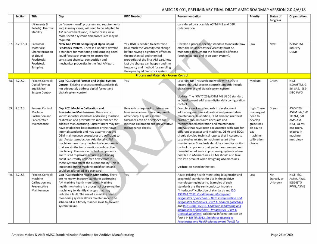
AMSC 18-001, PRELIMINARY FINAL DRAFT AMSC ROADMAP VERSION 2.0 4/6/18
America Makes & ANSI AMSC Standardization Roadmap for Additive Manufacturing Page 26 of 260
Section Title Gap R&D Needed Recommendation Priority Status of Progress
Organization
(Filaments & Pellets): Thermal Stability
on “conventional” processes and requirements and, in many cases, will need to be adapted to AM requirements and, in some cases, new, more specific systems and procedures may be required.
considered by a possible ASTM F42 and D20 collaboration.
37. 2.2.1.5.3 Precursor Materials: Characterization of Liquid Feedstock: Feedstock Sampling
NEW Gap PM10: Sampling of Open Liquid Feedstock System. There is a need to develop a standard for monitoring and sampling open liquid feedstock systems to ensure the consistent chemical composition and mechanical properties in the final AM part.
Yes. R&D is needed to determine how much the viscosity can change before having a significant effect on the mechanical and chemical properties of the final AM part, how fast the change can happen and the frequency and method for sampling the open liquid feedstock system.
Develop a process-specific standard to indicate how often the liquid feedstock viscosity must be monitored throughout the feedstock’s lifetime (both in storage and in an open system).
Low New ISO/ASTM, Industry OEMs
Process and Materials - Process Control
38. 2.2.2.2 Process Control: Digital Format and Digital System Control
Gap PC1: Digital Format and Digital System Control. Existing process control standards do not adequately address digital format and digital system control.
Yes Leverage NIST research and work with SDOs to ensure that AM process control standards include digital format and digital system control. Update: The ISO/TC 261/ASTM F42 JG 56 standard in development addresses digital data configuration control.
Medium Green NIST, ISO/ASTM JG 56, SAE, IEEE-ISTO PWG
39. 2.2.2.3 Process Control: Machine Calibration and Preventative Maintenance
Gap PC2: Machine Calibration and Preventative Maintenance. There are no known industry standards addressing machine calibration and preventative maintenance for additive manufacturing. Current users may not have established best practices or their own internal standards and may assume that the OEM maintenance procedures are sufficient to start/restart production. Additionally, AM machines have many mechanical components that are similar to conventional subtractive machinery. The motion control components are trusted to provide accurate positioning and it is currently unknown how errors in these systems affect the output quality. This is important during machine qualification and could be addressed in a standard.
Research is required to determine how errors in machine components affect output quality so that tolerances can be developed for machine calibration and preventative maintenance checks
Complete work on standards in development addressing machine calibration and preventative maintenance. In addition, OEM and end user best practices should ensure adequate and recommended calibration and maintenance intervals that have been documented with data for different processes and machines. OEMs and SDOs should develop technical reports that incorporate case studies related to machine restart after maintenance. Standards should account for motion control components that guide measurement and remediation of error in positioning systems where possible in AM machines. OEMs should also take this into account when designing AM machines. Update: As noted in the text.
High. There is an urgent need to develop guidelines on day-to-day machine calibration checks.
Green AWS D20, ASTM F42/ISO TC 261, SAE AMS-AM, NIST, OEMs, end users, experts in machine metrology
40. 2.2.2.3 Process Control: Machine Calibration and Preventative Maintenance
Gap PC3: Machine Health Monitoring. There are no known industry standards addressing AM machine health monitoring. Machine health monitoring is a process of observing the machinery to identify changes that may indicate a fault. The use of a machine health monitoring system allows maintenance to be scheduled in a timely manner so as to prevent system failure.
Yes Adapt existing health monitoring (diagnostics and prognosis) standards for use in the additive manufacturing industry. Examples of such standards are the semiconductor industry “Interface A” collection of standards and ISO 13379-1:2012, Condition monitoring and diagnostics of machines - Data interpretation and diagnostics techniques - Part 1: General guidelines and ISO 13381-1:2015, Condition monitoring and diagnostics of machines - Prognostics - Part 1: General guidelines. Additional information can be found in NISTIR 8012, Standards Related to Prognostics and Health Management (PHM) for
Low Not Started, or Unknown
NIST, ISO, ASTM, AWS, IEEE-ISTO PWG, ASME
AMSC 18-001, PRELIMINARY FINAL DRAFT AMSC ROADMAP VERSION 2.0 4/6/18
America Makes & ANSI AMSC Standardization Roadmap for Additive Manufacturing Page 27 of 260
Section Title Gap R&D Needed Recommendation Priority Status of Progress
Organization
Manufacturing.1 Further research/guidelines/specifications may be needed. For example, NIST may be able to identify critical indicators that need to be documented or controlled to assist end users with quality assurance. See also Gap M6, Tracking Maintenance. Update: ASME has a non AM specific project concerning Advanced Monitoring, Diagnostics, and Prognostics for Manufacturing Operations.
41. 2.2.2.4 Process Control: Machine Qualification
Gap PC4: Machine Qualification. Current users may not have considered the influence of machine control on resulting product quality and material properties beyond form and fit, including machine-to-machine variation (even between machines of the same make and model). While guidelines for machine qualification can be developed, a broader view of part-specific, process-specific, material-specific, and application-specific recommended practices is needed.
Yes SDOs should develop qualification standards for AM machines to pass in order to provide a level of confidence that these machines can produce parts with the required material properties. In addition, SDOs should develop guidelines or technical reports that incorporate case studies of various part types and applications across materials. Additional research may be needed in relation to machine-to-machine variation and on key parameters. Update: As noted in the text.
Medium Green NIST, AWS, SAE AMS-AM, ASTM F42, NAVSEA, NASA MFSC
42. 2.2.2.5 Process Control: Parameter Control
Gap PC5: Parameter Control. As a result of the many sources of variability within and among AM parts, and because a complete understanding of the specific effects of so many build process parameters on AM part performance is not currently available in the AM industry, standards are needed to identify requirements for demonstrating that a set of build process parameters produces an acceptable part, and for ensuring that those build process parameters remain consistent from build to build.
Yes. Develop and establish one verifiable key process parameter that combines both material and process parameters (such as power absorption coefficient or power ratio parameter, verifiable by melt pool geometry, shown in the research) that is independent of material and machine brand. R&D is needed to verify the concept of power ratio as the single controlling parameter and its applicability to all materials and machine brands.
Develop a standard that identifies key build process parameters for AM machines, taking into account the different processes, materials, industry-specific applications, and machines involved. Complete work on AWS D20.1. See also Gap QC3 on harmonizing Q&C terminology for process parameters. Update: As noted in the text, AWS D20.1 is being developed. ASTM F42 process and materials standards cover the parameters for PBF and Inconel 625 but not the values. SAE AMS7100 is trying to address FDM process control including setting parameters for the aerospace industry. SAE AMS7003 includes an appendix on PBF-L process characteristics but contains no values.
Medium Green AWS D20, ASTM F42, SAE AMS-AM, OEMs, IEEE-ISTO PWG
43. 2.2.2.6 Process Control: Adverse Machine Environmental Conditions: Effect on Component Quality
Gap PC6: Adverse Machine Environmental Conditions: Effect on Component Quality. There is a need for more research as well as standards or specifications that address AM machines being able to work in adverse environmental conditions.
Yes Develop standards and specifications to address external environmental factors that could negatively impact component quality. Update: None provided.
Low Unknown OEMs, DoD for military-specific operational environments, ASTM
44. 2.2.2.7 Process Control: Precursor Material Handling: Use, Re-use, Mixing,
Gap PC7: Recycle & Re-use of Materials. There are many practices in the materials industry of how to recycle, re-use, and revert materials in production. They are also highly material dependent. End users need to
Yes. Research should be conducted to understand the effects of mixing ratios of reused to virgin material.
Develop guidance as to how reused materials may be quantified and how their history should be tracked (e.g., number of re-uses, number of exposure hours [for a laser system], or some other
High Green ASTM F42/ISO TC 261, ASTM D20, MPIF, NIST, SAE,
1 http://dx.doi.org/10.6028/NIST.IR.8012
AMSC 18-001, PRELIMINARY FINAL DRAFT AMSC ROADMAP VERSION 2.0 4/6/18
America Makes & ANSI AMSC Standardization Roadmap for Additive Manufacturing Page 28 of 260
Section Title Gap R&D Needed Recommendation Priority Status of Progress
Organization
and Recycling Feedstock
understand best practices for how to qualify their various precursor material streams.
metric). Guidelines for sieving reused powder prior to mixing must be created. Update: ASTM F42.05 is looking at this issue via work items WK58223 and WK58221; that may flow up to F42.01 for test methods. SAE is looking at it on the aerospace side. NIST has published one study on the subject on metals but more R&D is needed before you can build parts to be qualified.
trusted end user-group
45. 2.2.2.7 Process Control: Precursor Material Handling: Use, Re-use, Mixing, and Recycling Feedstock
Gap PC8: Stratification. Powders used in additive manufacturing are composed of a distribution of particle sizes. Stratification may take place during container filling, transportation, or handling before and after being received by a user of powder. Users must know what conditioning is appropriate to ensure that the powder’s particle size distribution is consistent and acceptable for the specific process. There is currently a lack of guidance in this area.
Yes. Research should be conducted to understand the effect of stratification on particle size distribution of as-received powder and mixed powder prior to being put into service. The results from this work can be used to guide the re-blending of powder before being put into service.
Develop guidelines on how to maintain OEM characteristics in new use and re-use powder scenarios. There is documented variability in the final part properties in various AM processes; the AM community must either rule out stratification of powder precursor material or provide guidelines for mixing of lots to achieve acceptable particle size distribution. Update: None given.
Medium Unknown NIST, trusted end user-group, ASTM
46. 2.2.2.7 Process Control: Precursor Material Handling: Use, Re-use, Mixing, and Recycling Feedstock
Gap PC9: Environmental Conditions: Effects on Materials. AM materials can be sensitive to changes in environmental conditions including temperature, humidity, and ultraviolet radiation. Therefore, guidance must be provided to ensure the environmental conditions in which the material is used and stored remain within acceptable ranges. No standards or specifications have been identified regarding this topic.
Yes Develop guidance on the storage of AM materials so that AM materials are stored and used in environments with acceptable conditions. Research should be conducted to identify these ranges. Update: UL 3400, Outline of Investigation for Additive Manufacturing Facility Safety Management, is a document for the evaluation and certification of any additive manufacturing facility that uses powder as the initial form of feedstock material to print parts. It identifies the potential hazards within an AM facility, which includes environmental conditions. It does not provide specific reference to acceptable ranges for material storage within a facility. The effect of environmental conditions on AM materials can be dependent on a number of factors, which can vary by facility. UL 3400 provides guidance based on the requirements and conditions of the facility being evaluated. ASTM F42.06 is looking at environmental conditions for storage via work item ASTM WK59813, New Guide for Hazard Risk Ranking and Safety Defense.
High Green ASTM F42/ISO TC 261, NIST, SAE, UL, Powder Manufacturers/Suppliers
47. 2.2.2.7 Process Control: Precursor Material Handling: Use, Re-use, Mixing, and Recycling Feedstock
Gap PC10. Re-use of Material that Has Not Been Processed. There is a lack of industry guidance on the re-use of material that has not been processed.
Yes Develop a standard for the re-use of material that was not processed but is already within the system (e.g., for inkjet it can be in the plumbing, the reservoirs, the printing heads, etc.). Update: No update provided.
Medium Unknown ISO/ASTM
AMSC 18-001, PRELIMINARY FINAL DRAFT AMSC ROADMAP VERSION 2.0 4/6/18
America Makes & ANSI AMSC Standardization Roadmap for Additive Manufacturing Page 29 of 260
Section Title Gap R&D Needed Recommendation Priority Status of Progress
Organization
48. 2.2.2.7 Process Control: Precursor Material Handling: Use, Re-use, Mixing, and Recycling Feedstock
Gap PC11: Re-use of Material that Has Been Processed. There is a lack of industry guidance on the re-use of material that was already processed.
Yes Develop a standard for re-use of material that was already processed and cannot be reused as precursor material. For inkjet, there are two concerns: Material that was jetted but not polymerized and material that was polymerized to some extent (waste from each processed layer or the actual support material). Example: non-polymerized material that was jetted can be reused as material to fill bulky areas of the model (by filtering, re-jetting, and polymerizing). Update: None provided.
Low Unknown ASTM
49. 2.2.2.8 Process Control: Precursor Material Flow Monitoring: Directed Energy Deposition (powder)
Gap PC12: Precursor Material Flow Monitoring. There is no known standard for defining: • Method of DED process powder flow monitoring • Location of monitoring • Accuracy of flow monitoring • Standardized calibration process of flow
Yes Develop a standard for DED process powder flow monitoring so that operators/users will have a way to ensure the powder flow is coming out consistently and with minimal fluctuations so as to not alter the desired build and its properties. See also Gap PM1 on flowability. Update: None provided.
Medium Unknown NIST, ISO/ASTM
50. 2.2.2.8 Process Control: Precursor Material Flow Monitoring: Inkjet (Material Jetting)
PC13: Flow Parameters for Material Jetting. No published standards or standards in development have been identified for monitoring and control of all flow related parameters for material jetting.
Yes Develop a standard for monitoring and controlling all flow parameters for material jetting such as flow rate, temperature, viscosity, pressure level, wetting of the orifice plate, etc. This standard should include: • Monitoring and controlling similar flow in different material feeding channels. This is needed to allow multi-material printing while minimizing cross talk or non-uniformity between channels keeping quality of all printed materials. • Controlling the thickness of the printed layer. In material jetting, the material flows to the surface and controlling the thickness of each layer is clearly critical to maintain quality. The layer thickness can be controlled by controlling the material flow within the system and within the printing heads as well as by direct measurement after deposition. • Expanding the performance envelope to enable more degrees of freedom for the flow of material. For example, to enable a wider range of temperatures, humidity control, oxygen level control, ink recirculation in the print heads, etc. All this can allow using more viscous materials, with larger filler particles and exotic materials that might not be compatible with the print head materials in a standard environment. Update: None provided.
Low Unknown NIST, OEMs, ASTM, IEEE-ISTO PWG
51. 2.2.2.9 Process Control: Environmental Health and Safety:
Gap PC14: Environmental Health and Safety: Protection of Machine Operators. There is a need for standards to address environmental health and safety (EHS) in the AM process.
Yes Recommend creating a standard addressing EHS issues relative to additive machines (power, laser, handling, air quality, etc.). Physical measurement of operator exposure to AM materials is one of the
High Green ASTM F42/ISO TC 261, UL, ASSE, B11, LIA
AMSC 18-001, PRELIMINARY FINAL DRAFT AMSC ROADMAP VERSION 2.0 4/6/18
America Makes & ANSI AMSC Standardization Roadmap for Additive Manufacturing Page 30 of 260
Section Title Gap R&D Needed Recommendation Priority Status of Progress
Organization
Protection of Machine Operators
Typical hazards to be addressed include: guarding from moving parts that are not protected from contact; chemical handling (liquids, powders, wires); air emissions (dusts, vapors, fumes); noise (cleaning apparatus); electrical (water wash systems, electro-static systems); flammable/combustible cleaning materials; solid waste; laser use (sintering processes); and UV light (may require eye and skin protection based on design).
most critical needs and can be leveraged from existing industry standards. As noted in the text, research is underway. Update: UL has published UL 3400, Outline of Investigation for Additive Manufacturing Facility Safety Management, for the evaluation and certification of any additive manufacturing facility that uses powder feedstock to print parts. ASTM WK59813, New Guide for Hazard Risk Ranking and Safety Defense, is being developed to cover risks associated with different types of AM technologies and the recommended PPE and safety measures.
(Z136), ISO/TC 262
52. 2.2.2.10 Process Control: Configuration Management: Cybersecurity
Gap PC15. Configuration Management: Cybersecurity. Best practices for maintaining and controlling the programming environment for additive processes are needed to ensure repeatable product quality.
Yes Develop best practices to protect digital files used in the AM process. See also Gap M7 on cybersecurity for maintenance. Update: None provided.
Medium Unknown America Makes, NIST, UL, IEEE-ISTO PWG
53. 2.2.2.11 Process Control: In-Process Monitoring
Gap PC16: In-Process Monitoring. No published standards have been identified that address 1) the conversion of in-process monitoring data into an accurate 3D file representing the part manufactured, or 2) the use of in-process monitoring data to self-monitor and self-calibrate processing equipment. More than likely, there will be no “one size fits all” standard for any given additive process, piece of equipment, or material. It would be highly dependent on end user analytics of OEM or internally developed sensing systems. A standard guide is being developed in ASTM E07 (WK62181) that covers conversion of in-process monitoring data into an accurate 3D file representing the part manufactured, based on real-time measurement of part dimensions, surface finish, density, hot spots, or defect state during the build. Ideally, the information gathered during in-process monitoring is used to evaluate part acceptance, as a go/no-go before expensive post-processing operations are performed, and/or to guide NDE performed on the part after build.
Yes. Seamless incorporation of sensor-based monitoring techniques into the build without interfering with the build is nontrivial. While commercial based systems have been developed (for example, visible-spectrum layer-wise imaging; co-axial melt pool monitoring (visible or near-infrared); infrared, off-axis thermography; single-point, and off-axis pyrometry and/or photodetectors), other techniques (for example, spectroscopic measurements of plume; high speed visible-spectrum imaging (stationary view); single-point surface profilometry; and in-situ laser ultrasonic or AE monitoring) are lower TRL and warrant additional R&D.
Issue standards on in-process monitoring of the feedstock (supply ratios and other metrics), process conditions (atmosphere, humidity), process parameters (beam diagnostics such as location, laser power, scan width, scan rate), and the part during build (dimensions, surface finish, density, hot spots, defect state). See also Gap D22 on the use of physics-based models and simulation tools (analytics). Update: ASTM E7.10 is developing a draft guide WK62181 on in-process monitoring covering commercial based systems (visible-spectrum layer-wise imaging; co-axial melt pool monitoring (visible or near-infrared); infrared, off-axis thermography; single-point, off-axis pyrometry and/or photodetectors).Potentially, other techniques that show promise will be included (spectroscopic measurements of plume; high speed visible-spectrum imaging (stationary view); single-point surface profilometry; and in-situ laser ultrasonic or AE monitoring). The goal of WK62181 is to obtain a layer-by-layer (3D) file or quality record showing the as-built part is defect-free or contains no critical flaws, or exhibits an in-family (nominal) response when interrogated during the build. WK62181 does not address control of equipment functions such as feedstock supply, process conditions, or process parameters (no known gap), or physics-based models or simulation tools used in prognostics or diagnostics (see Gap D22).
Medium, given the relatively low technology readiness level (TRL) state of the art
Yellow ASTM E07.10
Process and Materials – Post-processing
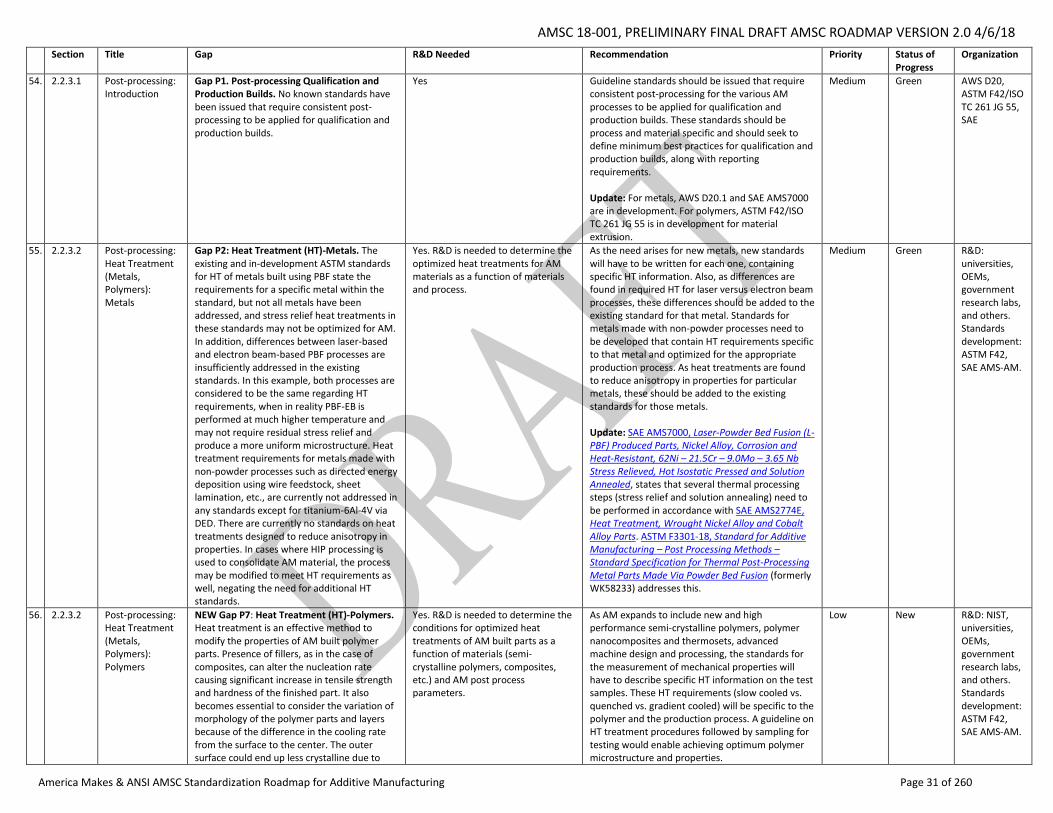
AMSC 18-001, PRELIMINARY FINAL DRAFT AMSC ROADMAP VERSION 2.0 4/6/18
America Makes & ANSI AMSC Standardization Roadmap for Additive Manufacturing Page 31 of 260
Section Title Gap R&D Needed Recommendation Priority Status of Progress
Organization
54. 2.2.3.1 Post-processing: Introduction
Gap P1. Post-processing Qualification and Production Builds. No known standards have been issued that require consistent post-processing to be applied for qualification and production builds.
Yes Guideline standards should be issued that require consistent post-processing for the various AM processes to be applied for qualification and production builds. These standards should be process and material specific and should seek to define minimum best practices for qualification and production builds, along with reporting requirements. Update: For metals, AWS D20.1 and SAE AMS7000 are in development. For polymers, ASTM F42/ISO TC 261 JG 55 is in development for material extrusion.
Medium Green AWS D20, ASTM F42/ISO TC 261 JG 55, SAE
55. 2.2.3.2 Post-processing: Heat Treatment (Metals, Polymers): Metals
Gap P2: Heat Treatment (HT)-Metals. The existing and in-development ASTM standards for HT of metals built using PBF state the requirements for a specific metal within the standard, but not all metals have been addressed, and stress relief heat treatments in these standards may not be optimized for AM. In addition, differences between laser-based and electron beam-based PBF processes are insufficiently addressed in the existing standards. In this example, both processes are considered to be the same regarding HT requirements, when in reality PBF-EB is performed at much higher temperature and may not require residual stress relief and produce a more uniform microstructure. Heat treatment requirements for metals made with non-powder processes such as directed energy deposition using wire feedstock, sheet lamination, etc., are currently not addressed in any standards except for titanium-6Al-4V via DED. There are currently no standards on heat treatments designed to reduce anisotropy in properties. In cases where HIP processing is used to consolidate AM material, the process may be modified to meet HT requirements as well, negating the need for additional HT standards.
Yes. R&D is needed to determine the optimized heat treatments for AM materials as a function of materials and process.
As the need arises for new metals, new standards will have to be written for each one, containing specific HT information. Also, as differences are found in required HT for laser versus electron beam processes, these differences should be added to the existing standard for that metal. Standards for metals made with non-powder processes need to be developed that contain HT requirements specific to that metal and optimized for the appropriate production process. As heat treatments are found to reduce anisotropy in properties for particular metals, these should be added to the existing standards for those metals. Update: SAE AMS7000, Laser-Powder Bed Fusion (L-PBF) Produced Parts, Nickel Alloy, Corrosion and Heat-Resistant, 62Ni – 21.5Cr – 9.0Mo – 3.65 Nb Stress Relieved, Hot Isostatic Pressed and Solution Annealed, states that several thermal processing steps (stress relief and solution annealing) need to be performed in accordance with SAE AMS2774E, Heat Treatment, Wrought Nickel Alloy and Cobalt Alloy Parts. ASTM F3301-18, Standard for Additive Manufacturing – Post Processing Methods – Standard Specification for Thermal Post-Processing Metal Parts Made Via Powder Bed Fusion (formerly WK58233) addresses this.
Medium Green R&D: universities, OEMs, government research labs, and others. Standards development: ASTM F42, SAE AMS-AM.
56. 2.2.3.2 Post-processing: Heat Treatment (Metals, Polymers): Polymers
NEW Gap P7: Heat Treatment (HT)-Polymers. Heat treatment is an effective method to modify the properties of AM built polymer parts. Presence of fillers, as in the case of composites, can alter the nucleation rate causing significant increase in tensile strength and hardness of the finished part. It also becomes essential to consider the variation of morphology of the polymer parts and layers because of the difference in the cooling rate from the surface to the center. The outer surface could end up less crystalline due to
Yes. R&D is needed to determine the conditions for optimized heat treatments of AM built parts as a function of materials (semi-crystalline polymers, composites, etc.) and AM post process parameters.
As AM expands to include new and high performance semi-crystalline polymers, polymer nanocomposites and thermosets, advanced machine design and processing, the standards for the measurement of mechanical properties will have to describe specific HT information on the test samples. These HT requirements (slow cooled vs. quenched vs. gradient cooled) will be specific to the polymer and the production process. A guideline on HT treatment procedures followed by sampling for testing would enable achieving optimum polymer microstructure and properties.
Low New R&D: NIST, universities, OEMs, government research labs, and others. Standards development: ASTM F42, SAE AMS-AM.
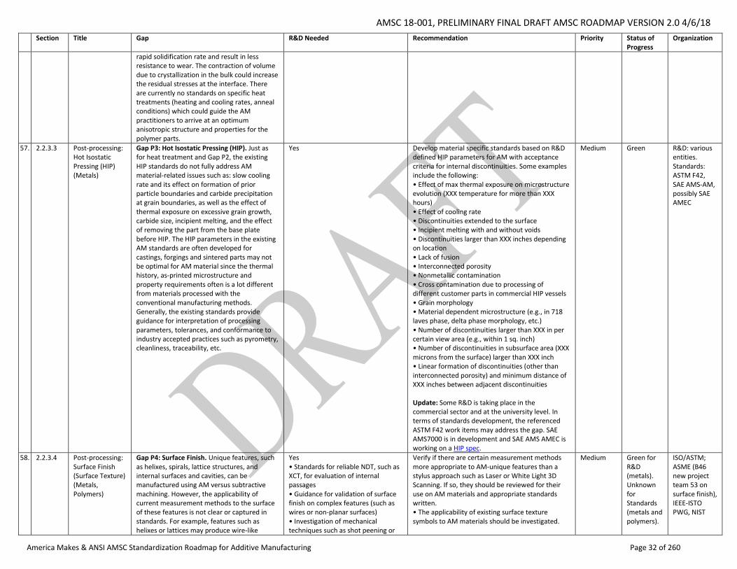
AMSC 18-001, PRELIMINARY FINAL DRAFT AMSC ROADMAP VERSION 2.0 4/6/18
America Makes & ANSI AMSC Standardization Roadmap for Additive Manufacturing Page 32 of 260
Section Title Gap R&D Needed Recommendation Priority Status of Progress
Organization
rapid solidification rate and result in less resistance to wear. The contraction of volume due to crystallization in the bulk could increase the residual stresses at the interface. There are currently no standards on specific heat treatments (heating and cooling rates, anneal conditions) which could guide the AM practitioners to arrive at an optimum anisotropic structure and properties for the polymer parts.
57. 2.2.3.3 Post-processing: Hot Isostatic Pressing (HIP) (Metals)
Gap P3: Hot Isostatic Pressing (HIP). Just as for heat treatment and Gap P2, the existing HIP standards do not fully address AM material-related issues such as: slow cooling rate and its effect on formation of prior particle boundaries and carbide precipitation at grain boundaries, as well as the effect of thermal exposure on excessive grain growth, carbide size, incipient melting, and the effect of removing the part from the base plate before HIP. The HIP parameters in the existing AM standards are often developed for castings, forgings and sintered parts may not be optimal for AM material since the thermal history, as-printed microstructure and property requirements often is a lot different from materials processed with the conventional manufacturing methods. Generally, the existing standards provide guidance for interpretation of processing parameters, tolerances, and conformance to industry accepted practices such as pyrometry, cleanliness, traceability, etc.
Yes Develop material specific standards based on R&D defined HIP parameters for AM with acceptance criteria for internal discontinuities. Some examples include the following: • Effect of max thermal exposure on microstructure evolution (XXX temperature for more than XXX hours) • Effect of cooling rate • Discontinuities extended to the surface • Incipient melting with and without voids • Discontinuities larger than XXX inches depending on location • Lack of fusion • Interconnected porosity • Nonmetallic contamination • Cross contamination due to processing of different customer parts in commercial HIP vessels • Grain morphology • Material dependent microstructure (e.g., in 718 laves phase, delta phase morphology, etc.) • Number of discontinuities larger than XXX in per certain view area (e.g., within 1 sq. inch) • Number of discontinuities in subsurface area (XXX microns from the surface) larger than XXX inch • Linear formation of discontinuities (other than interconnected porosity) and minimum distance of XXX inches between adjacent discontinuities Update: Some R&D is taking place in the commercial sector and at the university level. In terms of standards development, the referenced ASTM F42 work items may address the gap. SAE AMS7000 is in development and SAE AMS AMEC is working on a HIP spec.
Medium Green R&D: various entities. Standards: ASTM F42, SAE AMS-AM, possibly SAE AMEC
58. 2.2.3.4 Post-processing: Surface Finish (Surface Texture) (Metals, Polymers)
Gap P4: Surface Finish. Unique features, such as helixes, spirals, lattice structures, and internal surfaces and cavities, can be manufactured using AM versus subtractive machining. However, the applicability of current measurement methods to the surface of these features is not clear or captured in standards. For example, features such as helixes or lattices may produce wire-like
Yes • Standards for reliable NDT, such as XCT, for evaluation of internal passages • Guidance for validation of surface finish on complex features (such as wires or non-planar surfaces) • Investigation of mechanical techniques such as shot peening or
Verify if there are certain measurement methods more appropriate to AM-unique features than a stylus approach such as Laser or White Light 3D Scanning. If so, they should be reviewed for their use on AM materials and appropriate standards written. • The applicability of existing surface texture symbols to AM materials should be investigated.
Medium Green for R&D (metals). Unknown for Standards (metals and polymers).
ISO/ASTM; ASME (B46 new project team 53 on surface finish), IEEE-ISTO PWG, NIST
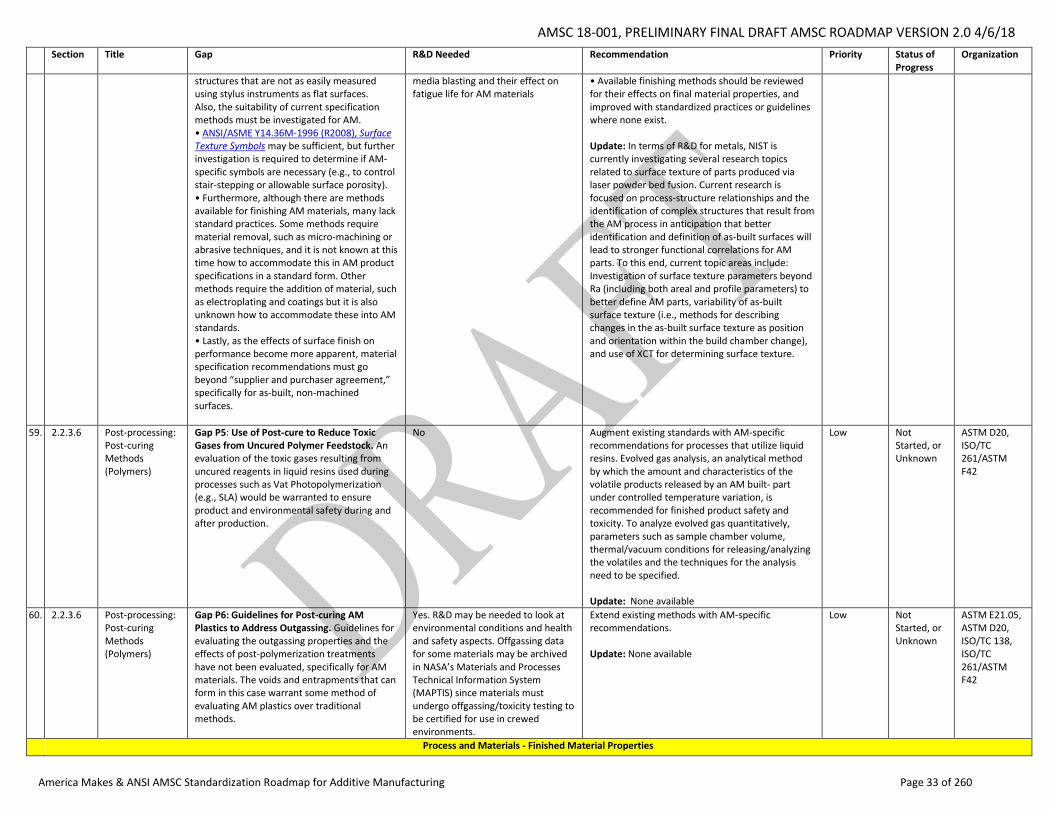
AMSC 18-001, PRELIMINARY FINAL DRAFT AMSC ROADMAP VERSION 2.0 4/6/18
America Makes & ANSI AMSC Standardization Roadmap for Additive Manufacturing Page 33 of 260
Section Title Gap R&D Needed Recommendation Priority Status of Progress
Organization
structures that are not as easily measured using stylus instruments as flat surfaces. Also, the suitability of current specification methods must be investigated for AM. • ANSI/ASME Y14.36M-1996 (R2008), Surface Texture Symbols may be sufficient, but further investigation is required to determine if AM-specific symbols are necessary (e.g., to control stair-stepping or allowable surface porosity). • Furthermore, although there are methods available for finishing AM materials, many lack standard practices. Some methods require material removal, such as micro-machining or abrasive techniques, and it is not known at this time how to accommodate this in AM product specifications in a standard form. Other methods require the addition of material, such as electroplating and coatings but it is also unknown how to accommodate these into AM standards. • Lastly, as the effects of surface finish on performance become more apparent, material specification recommendations must go beyond “supplier and purchaser agreement,” specifically for as-built, non-machined surfaces.
media blasting and their effect on fatigue life for AM materials
• Available finishing methods should be reviewed for their effects on final material properties, and improved with standardized practices or guidelines where none exist. Update: In terms of R&D for metals, NIST is currently investigating several research topics related to surface texture of parts produced via laser powder bed fusion. Current research is focused on process-structure relationships and the identification of complex structures that result from the AM process in anticipation that better identification and definition of as-built surfaces will lead to stronger functional correlations for AM parts. To this end, current topic areas include: Investigation of surface texture parameters beyond Ra (including both areal and profile parameters) to better define AM parts, variability of as-built surface texture (i.e., methods for describing changes in the as-built surface texture as position and orientation within the build chamber change), and use of XCT for determining surface texture.
59. 2.2.3.6 Post-processing: Post-curing Methods (Polymers)
Gap P5: Use of Post-cure to Reduce Toxic Gases from Uncured Polymer Feedstock. An evaluation of the toxic gases resulting from uncured reagents in liquid resins used during processes such as Vat Photopolymerization (e.g., SLA) would be warranted to ensure product and environmental safety during and after production.
No Augment existing standards with AM-specific recommendations for processes that utilize liquid resins. Evolved gas analysis, an analytical method by which the amount and characteristics of the volatile products released by an AM built- part under controlled temperature variation, is recommended for finished product safety and toxicity. To analyze evolved gas quantitatively, parameters such as sample chamber volume, thermal/vacuum conditions for releasing/analyzing the volatiles and the techniques for the analysis need to be specified. Update: None available
Low Not Started, or Unknown
ASTM D20, ISO/TC 261/ASTM F42
60. 2.2.3.6 Post-processing: Post-curing Methods (Polymers)
Gap P6: Guidelines for Post-curing AM Plastics to Address Outgassing. Guidelines for evaluating the outgassing properties and the effects of post-polymerization treatments have not been evaluated, specifically for AM materials. The voids and entrapments that can form in this case warrant some method of evaluating AM plastics over traditional methods.
Yes. R&D may be needed to look at environmental conditions and health and safety aspects. Offgassing data for some materials may be archived in NASA’s Materials and Processes Technical Information System (MAPTIS) since materials must undergo offgassing/toxicity testing to be certified for use in crewed environments.
Extend existing methods with AM-specific recommendations. Update: None available
Low Not Started, or Unknown
ASTM E21.05, ASTM D20, ISO/TC 138, ISO/TC 261/ASTM F42
Process and Materials - Finished Material Properties
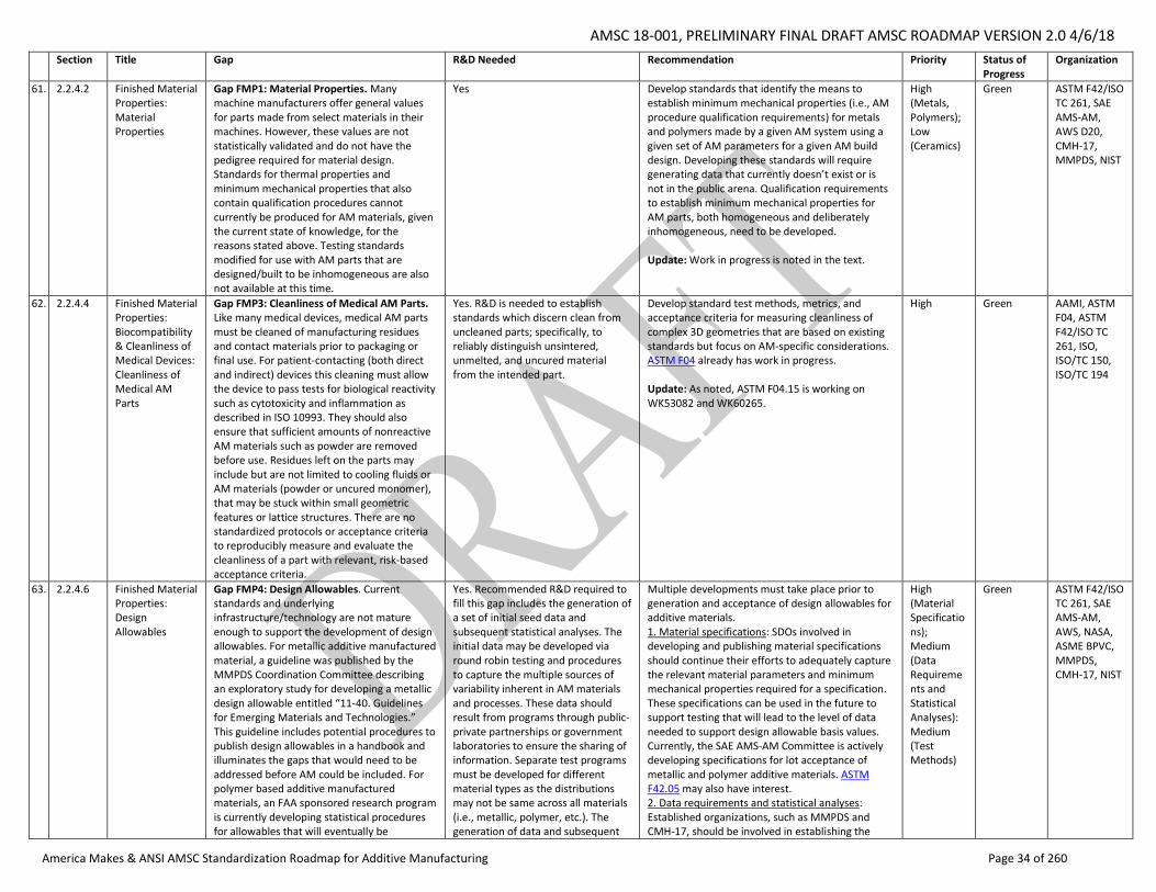
AMSC 18-001, PRELIMINARY FINAL DRAFT AMSC ROADMAP VERSION 2.0 4/6/18
America Makes & ANSI AMSC Standardization Roadmap for Additive Manufacturing Page 34 of 260
Section Title Gap R&D Needed Recommendation Priority Status of Progress
Organization
61. 2.2.4.2 Finished Material Properties: Material Properties
Gap FMP1: Material Properties. Many machine manufacturers offer general values for parts made from select materials in their machines. However, these values are not statistically validated and do not have the pedigree required for material design. Standards for thermal properties and minimum mechanical properties that also contain qualification procedures cannot currently be produced for AM materials, given the current state of knowledge, for the reasons stated above. Testing standards modified for use with AM parts that are designed/built to be inhomogeneous are also not available at this time.
Yes Develop standards that identify the means to establish minimum mechanical properties (i.e., AM procedure qualification requirements) for metals and polymers made by a given AM system using a given set of AM parameters for a given AM build design. Developing these standards will require generating data that currently doesn’t exist or is not in the public arena. Qualification requirements to establish minimum mechanical properties for AM parts, both homogeneous and deliberately inhomogeneous, need to be developed. Update: Work in progress is noted in the text.
High (Metals, Polymers); Low (Ceramics)
Green ASTM F42/ISO TC 261, SAE AMS-AM, AWS D20, CMH-17, MMPDS, NIST
62. 2.2.4.4 Finished Material Properties: Biocompatibility & Cleanliness of Medical Devices: Cleanliness of Medical AM Parts
Gap FMP3: Cleanliness of Medical AM Parts. Like many medical devices, medical AM parts must be cleaned of manufacturing residues and contact materials prior to packaging or final use. For patient-contacting (both direct and indirect) devices this cleaning must allow the device to pass tests for biological reactivity such as cytotoxicity and inflammation as described in ISO 10993. They should also ensure that sufficient amounts of nonreactive AM materials such as powder are removed before use. Residues left on the parts may include but are not limited to cooling fluids or AM materials (powder or uncured monomer), that may be stuck within small geometric features or lattice structures. There are no standardized protocols or acceptance criteria to reproducibly measure and evaluate the cleanliness of a part with relevant, risk-based acceptance criteria.
Yes. R&D is needed to establish standards which discern clean from uncleaned parts; specifically, to reliably distinguish unsintered, unmelted, and uncured material from the intended part.
Develop standard test methods, metrics, and acceptance criteria for measuring cleanliness of complex 3D geometries that are based on existing standards but focus on AM-specific considerations. ASTM F04 already has work in progress. Update: As noted, ASTM F04.15 is working on WK53082 and WK60265.
High Green AAMI, ASTM F04, ASTM F42/ISO TC 261, ISO, ISO/TC 150, ISO/TC 194
63. 2.2.4.6 Finished Material Properties: Design Allowables
Gap FMP4: Design Allowables. Current standards and underlying infrastructure/technology are not mature enough to support the development of design allowables. For metallic additive manufactured material, a guideline was published by the MMPDS Coordination Committee describing an exploratory study for developing a metallic design allowable entitled “11-40. Guidelines for Emerging Materials and Technologies.” This guideline includes potential procedures to publish design allowables in a handbook and illuminates the gaps that would need to be addressed before AM could be included. For polymer based additive manufactured materials, an FAA sponsored research program is currently developing statistical procedures for allowables that will eventually be
Yes. Recommended R&D required to fill this gap includes the generation of a set of initial seed data and subsequent statistical analyses. The initial data may be developed via round robin testing and procedures to capture the multiple sources of variability inherent in AM materials and processes. These data should result from programs through public-private partnerships or government laboratories to ensure the sharing of information. Separate test programs must be developed for different material types as the distributions may not be same across all materials (i.e., metallic, polymer, etc.). The generation of data and subsequent
Multiple developments must take place prior to generation and acceptance of design allowables for additive materials. 1. Material specifications: SDOs involved in developing and publishing material specifications should continue their efforts to adequately capture the relevant material parameters and minimum mechanical properties required for a specification. These specifications can be used in the future to support testing that will lead to the level of data needed to support design allowable basis values. Currently, the SAE AMS-AM Committee is actively developing specifications for lot acceptance of metallic and polymer additive materials. ASTM F42.05 may also have interest. 2. Data requirements and statistical analyses: Established organizations, such as MMPDS and CMH-17, should be involved in establishing the
High (Material Specifications); Medium (Data Requirements and Statistical Analyses): Medium (Test Methods)
Green ASTM F42/ISO TC 261, SAE AMS-AM, AWS, NASA, ASME BPVC, MMPDS, CMH-17, NIST
AMSC 18-001, PRELIMINARY FINAL DRAFT AMSC ROADMAP VERSION 2.0 4/6/18
America Makes & ANSI AMSC Standardization Roadmap for Additive Manufacturing Page 35 of 260
Section Title Gap R&D Needed Recommendation Priority Status of Progress
Organization
submitted to CMH-17 for consideration to be published in a new volume.
analyses will help define the minimum requirements and statistical methods necessary for additive materials.
methodology required for deriving the allowables through a statistical process that takes into account the variability and parameters associated with additively manufactured materials. The MMPDS General Coordinating Committee, CMH-17 Executive Group, and/or other steering groups of organizations familiar with curating design allowable databases should develop guidelines on minimum data requirements and statistical processes. Although the key material/process parameters affecting allowables and in some cases the required test methods will differ, it is recommended to start with the currently available statistical analysis methods for metals and polymer composites as a baseline. 3. Test methods: Test standards organizations, such as ASTM/ISO, should provide recommendations on established test methods with special considerations for AM materials. If necessary, new coupon or component test methods should be developed. Update: At this time, no publicly available methodology for design allowables of additively manufactured materials exist. However, the three sections listed above (Material Specifications, Data Requirements and Statistical Analyses, and Test Methods) are all being addressed throughout multiple SDOs and other programs. Material specifications are being generated by multiple SDOs at this time. SAE has a Data Management Sub-Committee currently defining guidelines to generate specifications minimum values for both metals and polymers. In addition to the work in progress noted in the text and gap statement, ASME's BPVC committee is looking at this. Regarding characterization methods for metals, the MMPDS coordinating committee has concerns that existing data requirements and statistical analysis methods are not sufficient. Their primary concern is the level of maturity of standards and specifications needed to ensure consistent properties. Polymer AM material test methods have similar issues; methods can either be adopted from plastic or polymer matrix composites methods, both of which may need modification.
64. 2.2.4.7 Finished Material Properties: Microstructure
Gap FMP5: Microstructure. There is an inherent heterogeneity in the microstructure of metallic alloys made by AM that requires a standard for identification and quantification of the spatial variability of various microstructure features.
Yes. NIST should help develop Calphad databases suitable for non-equilibrium solidification.
ASTM should develop a standard for characterization and acceptance criteria of AM microstructures (both identification and quantification). Update: Nothing started in terms of ASTM work.
Medium Not Started, or Unknown
NIST, ASTM
AMSC 18-001, PRELIMINARY FINAL DRAFT AMSC ROADMAP VERSION 2.0 4/6/18
America Makes & ANSI AMSC Standardization Roadmap for Additive Manufacturing Page 36 of 260
Section Title Gap R&D Needed Recommendation Priority Status of Progress
Organization
Qualification & Certification (not covered elsewhere)
65. 2.3.1 Qualification & Certification: Introduction: Q&C Terminology
Gap QC1: Harmonization of AM Q&C Terminology. One of the challenges in discussing qualification and certification in AM is the ambiguity of the terms qualification, certification, verification, and validation, and how these terms are used by different industrial sectors when describing Q&C of materials, parts, processes, personnel, and equipment.
No Compare how the terms qualification, certification, verification and validation are used by industry sector. Update as needed existing quality management system standards and other terminology standards to harmonize definitions and encourage consistent use of terms across industry sectors with respect to AM. Update: In discussions between the AMSC advisory group and the SDOs, there was a general sense that relevant AM terminology could be captured in the ISO/ASTM 52900 document to the extent possible. However, that document does not currently address the disparities on Q&C terminology discussed here. As a general matter, ASME has been coordinating AM terminology activity with ASTM. SAE has noted the challenges of coming to consensus on terminology and has been using the ASTM definitions when they exist but coming up with new terms when a term is not defined. ASTM has offered to convene a virtual meeting with the SDOs and technical experts to discuss terminology. America Makes could help to promote such collaboration. This would be a step forward though it may not solve the issue of getting different sectors to adopt the same terminology.
High Green ASTM F42/ISO TC 261, AAMI, ASME, SAE
66. 2.3.3.1 Qualification & Certification: Aerospace Industry: Parts/Products
Gap QC2: AM Part Classification System for Consistent Qualification Standards. A part classification system is used to describe the level of risk associated with a part and may therefore be used as a metric to gauge appropriate qualification requirements. A common classification system for AM parts by industry sector is needed to provide consistent evaluation criteria for AM part risk. This should include a definition of criticality levels. Consistent risk criteria provide the basis for consistent expectations and levels of qualification rigor. Examples of classification systems can be found in the Lockheed Martin AM supplier quality checklist and NASA’s MSFC-STD-3716, Standard for Additively Manufactured Spaceflight Hardware by Laser Powder Bed Fusion in Metals, and the draft AWS D20.1 standard, which utilizes the part classification system identified in AWS D17.1/D17.1M:2017-AMD1, Specification for Fusion Welding of Aerospace Applications. Any industry requiring rigorous AM part qualification and system certification would
No A common classification system for AM parts should be defined along with the recommended minimum process and part qualification requirements commensurate with part risk for each classification level. Update: Writing a standard will be a challenge and will require coordination between the SDOs and relevant federal agencies. It may also be application-specific (e.g., spaceflight, military, etc.) It could be a series of documents from the agencies. This is more a harmonization issue. Procurement and level of testing required need to be addressed. The primary beneficiaries will be industry.
High Not Started ASTM F42/ISO TC 261, AWS, DoD, FAA, NASA, SAE
AMSC 18-001, PRELIMINARY FINAL DRAFT AMSC ROADMAP VERSION 2.0 4/6/18
America Makes & ANSI AMSC Standardization Roadmap for Additive Manufacturing Page 37 of 260
Section Title Gap R&D Needed Recommendation Priority Status of Progress
Organization
benefit from a common part classification system.
67. 2.3.3.2 Qualification & Certification: Defense Industry: Harmonizing Q&C Terminology for Process Parameters
Gap QC3: Harmonizing Q&C Terminology for Process Parameters. In order to enable full understanding of the given processes and to include this type of information in a process-agnostic TDP, and for purposes of qualification and/or certification, there must be standardization of process parameter terminology across machine manufacturers.
No Develop standardized terminology for process parameters for use across all AM equipment. Potentially, incorporate these into ISO/ASTM 52900:2015, Additive manufacturing - General principles - Terminology. See also Gap PC5 on parameter control. Update: As noted in the text.
Medium Green ASTM F42/ISO TC 261 JG 51, AWS D20, SAE AMS-AM, IEEE-ISTO PWG
68. 2.3.3.2 Qualification & Certification: Defense Industry: Source (i.e., Vendor) Approval
Gap QC4: DoD Source (i.e., Vendor) Approval Process for AM Produced Parts. As multiple methods of AM continue to mature, and new AM techniques are introduced, the government will need to fully understand the ramifications of each of these techniques, of what they are capable, and how certain AM procedures might lend themselves to some classes of parts and not others. Thus, not only must the government understand the differences, but how they should be assessed and tested, and what additional checks must be made on the end product before it can be qualified for use in a military platform. High pressures, temperatures, and other contained environments could impact the performance or life of safety-critical parts in ways that are not understood. Today, more research is required to determine the delta between traditional and AM methods.
Yes Starting with the most mature technologies, such as laser powder bed, develop standards to assess required checks for levels of criticality and safety as part of the source approval process. Update: It will be a challenge to develop one generic standard. DoD will need to specify the certification requirements that need to be put into such a standard and OEMs will need to share relevant information.
High Not Started ASME, ASTM F42/ISO TC 261, DoD, Industry, SAE, Service SYSCOMS
69. 2.3.3.2 Qualification & Certification: Defense Industry: Machine Operator Training and Qualification
Gap QC5: Machine Operator Training and Qualification. There is a need for standards or guidelines outlining AM training requirements.
No Recommendation: Develop AM operator training and qualification standards or guidelines. Training should cover the various AM materials and processes available in the market and be performance based to ensure consistent AM part quality. Develop additional standards for artisanal levels of competency and experience, delineating an individual’s expertise in the field or subsets of the AM field. Update: As noted in the text.
Low Green NASA, SAE, AWS, OEMs, UL, ASTM F42/ISO TC 261, AAMI
70. 2.3.3.3 Qualification & Certification: Medical Industry: Data Output from Imaging Sources
Gap QC6: Importing Ultrasound Data. The DICOM standard needs to be more widely promoted and may need to be revised to enable data to be imported from any ultrasound equipment similar to the CT scan or MRI data. There is a concern that the data coming from the ultrasound may not be providing adequately detailed images but this
Yes Promote and potentially revise the DICOM standard for importing data from ultrasound equipment. Use cases are obstetrics and pre-natal diagnosis. CP 1071 correction proposals should be approved. This relates to codes for cardiac ultrasound data target sites. Update: ISO/ASTM NP 52916, Additive manufacturing -- Data formats -- Standard
Medium Green DICOM, IEEE, ASTM F42/ISO TC 261 JG70
AMSC 18-001, PRELIMINARY FINAL DRAFT AMSC ROADMAP VERSION 2.0 4/6/18
America Makes & ANSI AMSC Standardization Roadmap for Additive Manufacturing Page 38 of 260
Section Title Gap R&D Needed Recommendation Priority Status of Progress
Organization
cannot be assessed until the interoperability concerns are eliminated.
specification for optimized medical image data, is being developed by ASTM F42 and ISO/TC 261 as JG 70.
71. 2.3.3.3 Qualification & Certification: Medical Industry: Data Acquisition for 3D Modeling: Protocols for Image Accuracy
Gap QC7: Protocols for Image Accuracy. Problems associated with data acquisition for 3D modeling either individually or in combination contribute to image inaccuracies that will result in inaccuracies of the 3D model and eventually the final device produced.
Yes. More R&D is needed on data for image accuracy before a standard can be developed.
Develop standard protocols for acquiring data for 3D modeling to ensure image accuracy. They may make use of standard image formats that capture enough information to facilitate size, orientation and color normalization and/or validation in post-processing of data. Update: ISO/ASTM NP 52916, Additive manufacturing -- Data formats -- Standard specification for optimized medical image data, is being developed by ASTM F42 and ISO/TC 261 as JG 70.
Medium Green DICOM, IEEE, ASME, ASTM F42/ISO TC 261, RSNA (Radiological Society of North America)
72. 2.3.3.3 Qualification & Certification: Medical Industry: Phantoms
Gap QC8: Phantoms. Material and process guidelines are needed for phantoms to provide reliable models for imaging experiments and to check the accuracy of the process. These would include which materials and AM process to use, based on what is being imaged and the modality in use (e.g., X-ray vs. ultrasound).
Yes Develop guidelines for creating and using phantoms to include material and process used, based on use. Similar to Gap QC7, they may make use of standard image formats that capture enough information to facilitate size, orientation and color normalization and/or validation in post-processing of data. Update: The RSNA 3DP Special Interest Group (SIG) is developing best practices for phantoms.
Medium Green Biomedical Engineering Society, NEMA/MITA, ISO, ASTM, RSNA
73. 2.3.3.3 Qualification & Certification: Medical Industry: Personnel Training for Image Data Set Processing
Gap QC9: Personnel Training for Image Data Set Processing. Currently, there are only limited qualification or certification programs (some are in process of formation) available for training personnel who are handling imaging data and preparing for AM printing.
No Develop certification programs for describing the requisite skills, qualification, and certification of personnel responsible for handling imaging data and preparing for printing. The SME organization currently has a program in development. Update: The SME AM3DP medical WG has developed competency models and is working on a detailed body of knowledge (BOK) to help recruit skilled workers to the profession, along with training, curriculum development, and a certification program.2 The FDA is involved with SME and RSNA. There is no separate interest at the federal level; certifications happen at the state level.
High Green SME, RSNA, ASTM F42/ISO TC 261
74. 2.3.3.3 Qualification & Certification: Medical Industry: Quality, Verification, and Validation of Medical Product 3D Models
Gap QC10: Verification of 3D Model. There are currently no standards for the final verification of a 3D model before it is approved for AM for the intended purpose (e.g., surgical planning vs. implantation; cranial replacement piece; cutting guides which have a low tolerance for anatomical discrepancy).
Yes, in terms of tolerances Develop standards for verification of the 3D model against the initial data. Ideally, they should identify efficient, automatable methods for identifying discrepancies. Update: ASTM F42/ISO 261 are looking at image quality as part of the model verification. ASME V&V 40 addresses verification and validation in computational modeling of medical devices. This
High Green ASTM F42/ISO TC 261, NEMA/MITA, AAMI, ASME, NIST, ACR
2 http://sme.org/am3dpjobmodel/
AMSC 18-001, PRELIMINARY FINAL DRAFT AMSC ROADMAP VERSION 2.0 4/6/18
America Makes & ANSI AMSC Standardization Roadmap for Additive Manufacturing Page 39 of 260
Section Title Gap R&D Needed Recommendation Priority Status of Progress
Organization
issue requires cooperation between clinical societies, the FDA and industry. It may also be a general, not only medical, concern.
75. 2.3.3.3 Qualification & Certification: Medical Industry: Resorbable Materials
Gap QC12: Resorbable Materials. There are few available standards for testing of degradation of the new resorbable metals/polymers in living tissues that cannot be achieved using existing standards and therefore a standard needs to be developed.
Yes, in terms of rate and amount of degradation for new polymers and resorbable metals.
Develop guidance on how to test the degradation of new resorbable metals/polymers to support material selection for AM. Update: None provided.
Medium Green ASTM F4, ISO, ISO/TC 150, ISO/TC 194
76. 2.3.3.3 Qualification & Certification: Medical Industry: Material Control Data and Procedures
Gap QC13: Material Control Data and Procedures. There is a need for well-established material control data and procedures. Materials are primarily manufactured through proprietary methods and, while recommended handling practices exist for each company and each product, standard procedures or standardized considerations are not available.
Yes A standard or specification describing a data set for material pedigree, recommended testing, and handling procedures would simplify evaluation of material suitability. Update: No update provided.
Low Unknown Material providers, ASTM
77. 2.3.3.3 Qualification & Certification: Medical Industry: Patient Imaging Files and Segmentation
Gap QC14: Segmentation. There are currently no standards for patient imaging files including the methods from standard-of-care medical images to print ready files. There is no group or entity that oversees segmentation within a clinical setting. RSNA has a special interest group that may set standards for segmentation and/or 3D printing. DICOM WG 17 also is looking at this.
No There is a need to create an augmented file specification for the DICOM file format. Incorporation of 3D files into the DICOM format will facilitate integration of 3D models into standard-of-care medical image databases present at all institutions. 3D models should include enough information to facilitate standardized methods for validation. Update: DICOM is addressing most of this. They will have public comment by the end of 2018, with a target for the first update being made by the second quarter of 2019.
Medium Green RSNA, DICOM, ASTM
78. 2.3.3.3 Qualification & Certification: Medical Industry: Validation of Sterilization Processes
Gap QC15: Sterilization of Anatomical Models. Anatomical models are frequently made in a healthcare setting and their final use may differ from the initial intended use. For instance, a surgeon may determine that a model patient education may be useful for reference in the operating room during the surgical procedure. If the models enter the sterile field they would require sterilization and the effects of sterilization on the geometric fidelity of the model should be assessed. If they are to come into contact with the patient the effects of sterilization on the materials are especially important. While many standards and industry best practices exist, the healthcare facilities may not have relevant experience.
No. Procedures and protocols for determining appropriate materials, sterilization cycles, and validation tests are already available but may not be implemented in healthcare settings.
Develop guides and best practices to help identify critical parameters and apply existing standards in a clinical setting. Update: The SME medical group is working on a biocompatibility worksheet for use with both models and surgical guides. This will not be a standard, but a guide of considerations.
Low Unknown R&D: OEMs. Guidance: AAMI, AOAC International, ASTM, ISO, PDA, USP, RSNA 3DP SIG.
79. 2.3.3.3 Qualification & Certification: Medical Industry: Sterilization of
NEW Gap QC16: Sterilization of Tissue Engineered Products. Tissue engineered products present a particularly challenging circumstance for sterility assurance. While
Maybe. A wide variety of aseptic processing and sterilization protocols exist for tissue engineered products, however no standards have been
Develop and validate standard methods of sterilizing and verifying the sterility of tissue engineered products, especially those that can be applied in healthcare settings.
Medium R&D: OEMs, FDA, BioFabUSA. Standards:
AMSC 18-001, PRELIMINARY FINAL DRAFT AMSC ROADMAP VERSION 2.0 4/6/18
America Makes & ANSI AMSC Standardization Roadmap for Additive Manufacturing Page 40 of 260
Section Title Gap R&D Needed Recommendation Priority Status of Progress
Organization
Tissue Engineered Products
using a validated aseptic processing protocol for tissue engineered products can maintain sterility, it is not always sufficient or practical. Risk management standards can help decrease the risks of contamination with best practices but not provide defined measures to ensure the sterility or assess contamination in a tissue engineered product.
published to address validation and testing of these protocols in tissue engineered products.
AAMI, ISO, ASTM F04, ASTM F42, AATB.
Nondestructive Evaluation (NDE)
80. 2.4.2 Nondestructive Evaluation: Common Defects Catalog Using a Common Language for AM Fabricated Parts: Terminology
Gap NDE1: Terminology for the Identification of AM Flaws Detectable by NDE Methods. An industry driven standard needs to be developed, with input from experts in metallurgy, NDE, and additive manufacturing fabrication, to identify flaws or flaw concentrations with the potential to jeopardize an AM object’s intended use. Many flaws have been identified but more effort is needed to agree on flaws terminology, providing appropriate names and descriptions.
No Develop standardized terminology to identify and describe flaws, and typical locations in a build. Update: As noted in the text.
High Green ASTM E07, ASTM F42/ISO TC 261, SAE AMS K, ASME BPVC, AWS D20, NIST
81. 2.4.2 Nondestructive Evaluation: Common Defects Catalog Using a Common Language for AM Fabricated Parts: Defect Catalog and Equipment Standardization
Gap NDE2: Standard for the Design and Manufacture of Artifacts or Phantoms Appropriate for Demonstrating NDE Capability. No published standards exist for the design or manufacture of artifacts or phantoms applicable to calibrating NDE equipment or demonstrating detection of naturally occurring flaws (lack of fusion, porosity, etc.), or intentionally added features (watermarks, embedded geometrical features, etc.). This standard should identify the naturally occurring flaws and intentional features. This standard should also include recommendations regarding the use of existing subtractive machined calibration standards or AM representative artifacts or phantoms.
No. This may not need R&D but it will require obtaining the knowledge necessary to state requirements and present supporting evidence, much like a round robin activity.
Complete work on WK56649, New Guide for Standard Practice/Guide for Intentionally Seeding Flaws in Additively Manufactured (AM) Parts, now proceeding as ISO/TC 261/ASTM F42 JG 60, to establish flaw types and conditions/parameters to recreate flaws using AM processes. Update: As noted, ASTM WK56649 is in development.
Medium Green ASTM F42/ISO TC 261
82. 2.4.3 Nondestructive Evaluation: Test Methods or Best Practice Guides for NDE of AM Parts
Gap NDE3: Standard Guide for the Application of NDE to Objects Produced by AM Processes. There is a need for an industry-driven standard led by nondestructive testing experts and supported by the additive manufacturing community to assess current inspection practices and provide an introduction to nondestructive testing and inspection requirements.
Yes. Round robin testing is underway in ASTM E07. A future need will be a precision and bias statement to generate standard test methods to accept/reject AM parts and in procurement of AM parts.
Complete work on ASTM WK47031, New Guide for Nondestructive Testing of Additive Manufactured Metal Parts Used in Aerospace Applications and ISO/ASTM NP 52905, Additive manufacturing – General Principles – Non-destructive testing of additive manufactured products, proceeding as ISO/TC 261/JG 59. Update: ASTM WK47031 and ISO/TC 261/JG 59 are in development. ASME is also looking at NDE vis a vis its boiler and pressure vessel code.
High Green ASTM E07, ASTM F42/ISO TC 261, ASME, NIST
83. 2.4.4 Nondestructive Evaluation: Dimensional
Gap NDE4: Dimensional Metrology of Internal Features. The utility of existing and draft CT standards are needed for the dimensional measurement of AM internal features.
Yes ASTM E07 should address the applicability of current and draft CT standards (E1570, E1695, WK61161, and WK61974) for measurement of internal features in additive manufactured parts,
Medium Green ASTM
AMSC 18-001, PRELIMINARY FINAL DRAFT AMSC ROADMAP VERSION 2.0 4/6/18
America Makes & ANSI AMSC Standardization Roadmap for Additive Manufacturing Page 41 of 260
Section Title Gap R&D Needed Recommendation Priority Status of Progress
Organization
Metrology of Internal Features
especially parts with complex geometry, internal features, and/or embedded features. Current CT metrology state-of-the-art needs to be tailored to evolving AM part inspection requirements. See also Gap D26, Measurement of AM Features/Verifying the designs of features such as lattices, etc. Update: As noted in the text.
84. 2.4.5 Nondestructive Evaluation: Data Fusion
Gap NDE5: Data Fusion. Since multiple sources and results are combined in data fusion, there is a possible issue of a non-linear data combination that can produce results that can be influenced by the user. Additionally, data fusion may employ statistical techniques that can also introduce some ambiguity in the results. While likely more accurate than non-data fusion techniques, introduction of multiple variables can be problematic. Data fusion techniques also require a certain level of expertise by the user and therefore there might be a need for user certification.
No The following are needed to address the gap: • Specific industry standards are needed for data fusion in AM NDT techniques • Expert education, training, and certification for AM data fusion in NDT Update: None available
Medium Unknown ASTM
85. 2.4.6 Nondestructive Evaluation: NDE of Polymers and Other Non-Metallic Materials
NEW Gap NDE6: NDE of Polymers and Other Non-Metallic Materials. No published or in development standards or specifications have been identified for NDE of polymers and other non-metallic materials.
Yes. Research who uses AM Fused Filaments or pellets with PAI/Torlon and/or carbon fiber reinforced filaments with a high degree of fiber loading to see what they are anticipating for testing requirements for NDE for strength or structural qualities.
There is a need for an industry-driven standard led by nondestructive testing experts and supported by the additive manufacturing community to assess current inspection practices and provide an introduction to nondestructive testing and inspection requirements for structural or load bearing polymers and other non-metallic materials. Use ASTM E2533-17e1 as a guideline when applicable.
Low New ASTM F42/ISO TC 261, ASTM E07, ASTM D20
86. 2.4.7 Nondestructive Evaluation: NDE of Counterfeit AM Parts
NEW Gap NDE7: NDE of Counterfeit AM Parts. No published or in development NDE standards for methods used to verify anti-counterfeiting methods.
Not at this time. Future R&D may be needed if an anti-counterfeiting method is developed which cannot be verified by existing NDE methods or standards.
Develop NDE methods and standards for anti-counterfeiting that are not addressed by existing methods or standards.
Low New ASTM F42/ISO TC 261, ASTM E07, SAE AMS-AM
87. 2.4.8 Nondestructive Evaluation: NDE Acceptance Criteria for Fracture Critical AM Parts
NEW Gap NDE8: NDE Acceptance Criteria for Fracture Critical AM Parts. There is a need for an industry standard that establishes NDE acceptance classes for fracture critical AM parts.
Yes. Well-characterized samples should be fabricated with controlled loadings of technologically important AM defects in order to conduct effect-of-defect studies.
Develop an industry standard that establishes different degrees of flaw concentrations for quality acceptance. Fabricate effect-of-defect samples with the appropriate level of fidelity, i.e., sufficient similarity between the defect state in sacrificial samples (for example, ASTM E8 compliant dogbones) with natural flaws in actual production parts.
Medium New ASTM F42 / ISO TC 261 JG 59, ASTM E07, ASTM E08 on Fracture and Fatigue
Maintenance and Repair
88. 2.5.2 Maintenance and Repair: Maintenance and Sustainment of Machines
Gap M1: AM Analyses in RCM and CBM. With respect to maintenance and sustainment of AM machines, standards for AM analyses in Reliability Centered Maintenance (RCM) and Conditioned Based Maintenance (CBM+) are needed.
No Update SAE JA 1012-2011, a guide to provide analytics for AM trade-offs in RCM and CBM+. Update: SAE G-11M, Maintainability, Supportability and Logistics Committee, will consider inclusion of analytics for AM trade-offs in the next update of JA1012_201108.
Medium Not Started SAE, ISO, ASTM
AMSC 18-001, PRELIMINARY FINAL DRAFT AMSC ROADMAP VERSION 2.0 4/6/18
America Makes & ANSI AMSC Standardization Roadmap for Additive Manufacturing Page 42 of 260
Section Title Gap R&D Needed Recommendation Priority Status of Progress
Organization
89. 2.5.3 Maintenance and Repair: Standard Repair Procedures
NEW GAP M9: Laser Based Additive Repair. Current standards do not specifically address the use of laser based systems (metal powder or wire feedstock) to additively repair parts or tools.
No Ensure that laser based additive repair processes are included in AWS D20.1
High New AWS
90. 2.5.3 Maintenance and Repair: Standard Repair Procedures
Gap M3: AM Level of Repair Analysis. Standards for AM LORA are needed. In performing a repair versus discard analysis, the use of AM can change the LORA decision due to shifts in factors relating to logistics delay time, spares availability, cost of spares, etc. Trade space would address reduction of time and increase in skill set (e.g., for qualified printer operators).
No Update SAE AS 1390-2014, Level of Repair Analysis (LORA), to include impact of AM on trade space of repairs. Update: SAE’s LCLS (Life Cycle Logistics Supportability) Committee plans to include AM in the upcoming revision of AS1390. Although the LCLS Committee has not opened a Work in Progress for AS1390, a team is working on revisions and has agreed to include AM. The G-11M is in the process of reorganizing but the chair has the AMSC requests on his radar. In addition, AMS2680C is currently under revision.
Medium Green SAE LCLS, SAE AMS-B, ISO, ASTM
91. 2.5.4 Maintenance and Repair: Standard Technical Inspection Processes
Gap M4: Physical Inspection of Parts Repaired Using AM. A standard Inspection process for component or tooling defects is needed to consider additive manufacturing technologies as potential solutions for preventative and corrective maintenance actions.
No Update SAE JA1011/1012 to include an inspection process for additive manufacturing repairs. Update: SAE G-11M, Maintainability, Supportability and Logistics Committee, will consider inclusion of an inspection process for AM repairs in the next update of JA1011_200908 and JA1012_201108.
Medium Not Started SAE, ISO/ASTM
92. 2.5.5 Maintenance and Repair: Model-Based Inspection
Gap M5: Model-Based Inspection. Standard practices for model-based inspection methods using AM are needed for repair assessments and scheduling.
No Develop standard practices for assessing level of damage for end-use parts. Update: No updated provided.
Medium Not Started, or Unknown
ASME, ISO/ASTM, Dimensional Metrology Standards Consortium
93. 2.5.6 Maintenance and Repair: Standards for Tracking Maintenance Operations
Gap M6: Tracking Maintenance. A standard is needed for how preventative maintenance operations of AM machines are tracked (e.g., monitoring printer health, need for servicing, etc.).
No • Develop a standard for tracking maintenance operations to ensure a printer is ready when needed. See also Gap PC3 on machine health monitoring. • Develop a standard to address emergency repair/limited life parts for urgent cases in the field. Update: ASTM WK58231, Additive Manufacturing - Creating Maintenance Schedules and Maintaining Metal Powder Bed Fusion Machines is in development.
Medium Green AWS, ASTM
94. 2.5.7 Maintenance and Repair: Cybersecurity for Maintenance
Gap M7: Cybersecurity for Maintenance. In support of on-site repairs, guidance is needed that addresses cybersecurity considerations for maintenance and repair of parts that have 3D models ready to print. Secure storage in a database should ensure that only authorized personnel can download files and print parts.
Yes Guidance is needed to ensure the integrity and safe storage of AM files as maintenance and repair operations may take place in an uncontrolled environment. See also gap PC15 on configuration management: cybersecurity. Update: No update provided.
Medium Not Started, or Unknown
NIST, NEMA/MITA, NDIA JWG, ASTM, IEEE-ISTO PWG
95. 2.5.8 Maintenance and Repair: Surface
Gap M8. Surface Preparation for Additive Repair. Standards are needed for chemical compatibility with additively manufactured
Yes Develop standards for approved chemical substances and mechanical processes used for the removal of coatings and plating on additively
Medium Not Started, or Unknown
ASTM, SAE, ISO
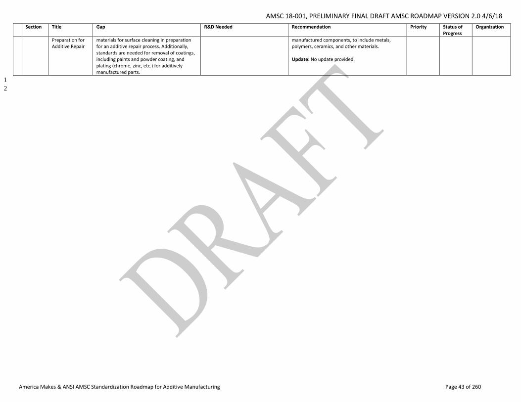
AMSC 18-001, PRELIMINARY FINAL DRAFT AMSC ROADMAP VERSION 2.0 4/6/18
America Makes & ANSI AMSC Standardization Roadmap for Additive Manufacturing Page 43 of 260
Section Title Gap R&D Needed Recommendation Priority Status of Progress
Organization
Preparation for Additive Repair
materials for surface cleaning in preparation for an additive repair process. Additionally, standards are needed for removal of coatings, including paints and powder coating, and plating (chrome, zinc, etc.) for additively manufactured parts.
manufactured components, to include metals, polymers, ceramics, and other materials. Update: No update provided.
1
2

AMSC 18-001, PRELIMINARY FINAL DRAFT AMSC ROADMAP VERSION 2.0 4/6/18
America Makes & ANSI AMSC Standardization Roadmap for Additive Manufacturing Page 44 of 260
1
2
3
4
5
6
7
8
9
[this page intentionally left blank] 10
11
12
13
AMSC 18-001, PRELIMINARY FINAL DRAFT AMSC ROADMAP VERSION 2.0 4/6/18
America Makes & ANSI AMSC Standardization Roadmap for Additive Manufacturing Page 45 of 260
1. Introduction 1
Additive Manufacturing (AM), sometimes referred to as three-dimensional (3D) printing (3DP), 2
encompasses a variety of processes wherein a 3D object is produced from a digital model by adding 3
successive layers of material to create the object. In name, it stands in contrast to traditional or 4
subtractive manufacturing where material is removed through machining or other means to create an 5
object. 6
AM as a field has grown significantly over the past several years, particularly in the aerospace, defense, 7
and medical sectors where it offers significant potential cost savings and shortening of the supply chain 8
by allowing parts to be manufactured on-site rather than at a distant supplier. In the medical field, AM 9
technologies are being used to create new, patient-specific, life-saving, medical devices. The industrial 10
sector, like medical, is also driven by AM-enabled designs for unique performance and efficiencies that 11
cannot be achieved through subtractive machining. 12
The process for making production AM parts may be summarized as follows: 13
Design the part for AM 14
Specify the materials from which the part will be built 15
Establish build parameters 16
Control the AM build process to achieve the desired part’s dimensions, structure, and 17
performance properties 18
Perform post-processing steps 19
Final testing 20
Certify the part’s fitness-for-use 21
Maintain/repair machines, parts, and systems 22
Standards, specifications, and related conformance and training programs, are integral to this process 23
and are a key enabler for the large-scale introduction and growth of AM. 24
1.1 Situational Assessment for AM 25
26
The AM industry began with the patenting and commercialization of Stereolithography (SLA) by 3D 27
Systems in 1986. In the early 1990s, Selective Laser Sintering (SLS) and Fused Deposition Modeling 28
(FDM) were patented and commercialized by DTM Corporation and Stratasys, Inc., respectively. 29
Applications for polymer AM materials and processes began with rapid prototyping and gradually 30
transitioned to include end use parts as improvements to materials, processes, and machines occurred. 31
Over time, 3DP technologies began transitioning from polymers to metals. In 2009, the ASTM committee 32
F42 was formed. In 2012, a public-private partnership came into existence as America Makes. With these 33
developments, 3DP has been branded “additive manufacturing” and become known by all. Call it an 34
overnight success, thirty years in the making. 35
AMSC 18-001, PRELIMINARY FINAL DRAFT AMSC ROADMAP VERSION 2.0 4/6/18
America Makes & ANSI AMSC Standardization Roadmap for Additive Manufacturing Page 46 of 260
Established as part of an Obama Administration initiative to promote advanced manufacturing and bring 1
high tech jobs to the “rust belt,” America Makes is the first pilot institute of Manufacturing USA, 2
previously known as the National Network for Manufacturing Innovation. Headquartered in 3
Youngstown, Ohio, America Makes is today the nation’s leading and collaborative partner in AM and 4
3DP technology research, discovery, creation, and innovation. It is managed and operated by the 5
National Center for Defense Manufacturing and Machining (NCDMM), which delivers optimized 6
manufacturing solutions that enhance the quality, affordability, maintainability, and rapid deployment 7
of existing and yet-to-be developed defense systems. 8
According to the Wohlers Report 2018, the AM market continues to grow rapidly, with an 80% increase 9
from 2016-17 in the number of metal AM systems sold. The number of companies that produced and 10
sold AM systems (machines that sell for more than $5,000) also increased from 97 in 2016 to 135 in 11
2017.3 Companies investing in AM technologies cut across sectors from aerospace to medical, athletic 12
footwear to automotive.4 13
1.2 Roadmap Background and Objectives 14
15
In the 1st quarter of 2016, America Makes commissioned the American National Standards Institute 16
(ANSI) to lead a program to identify which AM standards and specifications have been published, or are 17
being drafted, and where standards and specifications are needed. Thus, the America Makes & ANSI 18
Additive Manufacturing Standardization Collaborative (AMSC) was born. Federal agencies, including the 19
National Institute of Standards and Technology (NIST), Department of Defense (DoD), Federal Aviation 20
Administration (FAA), and others, as well as several standards development organizations (SDOs), were 21
instrumental in the formation of this collaborative. 22
23
America Makes engaged ANSI because of the Institute’s role as neutral coordinator and administrator of 24
the U.S. private sector system of voluntary standardization, and its past success in producing consensus-25
based standardization roadmaps when there was a perceived need for such coordination. The AMSC has 26
not undertaken to develop standards, something that ANSI’s charter expressly prohibits it from doing. 27
28
The establishment of the AMSC complemented America Makes’ formulation of a standards strategy for 29
AM. America Makes recognized the need and importance of AM standards and conformance procedures 30
to advance the adoption of AM technologies in the U.S., for example, for use by industry during 31
qualification of AM materials, processes, and systems, and by regulatory bodies during certification of 32
AM parts. 33
34
3 Scott, Clare, “Wohlers Report 2018 Details Overall 3D Printing Industry Growth, Major Gains in Metals,” 3DPrint.com, dated March 27, 2018, https://3dprint.com/208122/wohlers-report-2018/ 4 Huff, Ray and Wohlers, Terry, “AM Continues Rapid Ascent, Targets New Markets,” Advanced Manufacturing Now, dated March 30, 2018, http://advancedmanufacturing.org/am-continues-rapid-ascent-targets-new-markets/
AMSC 18-001, PRELIMINARY FINAL DRAFT AMSC ROADMAP VERSION 2.0 4/6/18
America Makes & ANSI AMSC Standardization Roadmap for Additive Manufacturing Page 47 of 260
America Makes also recognized that a number of SDOs, both U.S. based and elsewhere, are engaged in 1
producing voluntary consensus standards for AM to meet the needs of different industries. The 2
existence of these parallel standards-setting activities increased the need for U.S. leadership and 3
coordination to maintain a consistent, harmonized, and non-contradictory set of AM standards for use 4
by the AM community. 5
6
Thus, the AMSC project endeavored to bring together the community of stakeholders, including original 7
equipment manufacturers (OEMs), industry, government, academia, and SDOs, to develop a coherent 8
“roadmap” of existing and needed standards for additive manufacturing. Participation in the effort was 9
open to any AM stakeholder having operations in the United States, regardless of America Makes 10
and/or ANSI membership status. 11
12
Ultimately, the goal of this roadmap is to coordinate and accelerate the development of industry-wide 13
AM standards and specifications, consistent with stakeholder needs. The intent is to facilitate the 14
growth of the AM industry which to date has been largely dependent on OEM proprietary specifications. 15
16
The roadmap can thus be viewed as a tool designed to help focus resources in terms of participation by 17
stakeholders in the planning and development of industry-wide standards and related research and 18
development (R&D) activities to the extent R&D needs are identified. It is assumed that those reading 19
the document are directly affected stakeholders who have an understanding of AM technologies. 20
21
The roadmap’s focus is the industrial AM market, especially for the aerospace, defense, and medical 22
sectors. This is largely a reflection of the subject matter expertise of those who participated in its 23
development. That said, this document may have application to other industry sectors such as energy 24
and industrial gas turbines, automotive, etc. For example, following the release of the initial draft 25
roadmap for public comment, ANSI was contacted by the American Petroleum Institute (API), an ANSI 26
accredited SDO, who expressed interest in the topic and agreed to canvass its membership and gauge 27
their interest. Readers are encouraged to take note of gaps and recommendations that may not be 28
specific to their industry sector. 29
30
In terms of what can be deemed out of scope, the consumer desktop 3D printing market is generally not 31
addressed in this report. 32
33
1.3 How the Roadmap Was Developed 34
To develop the roadmap, the AMSC took the approach of doing a life-cycle assessment of an AM part, 35
from initial design, through production, and ending with post-production testing, qualification, and 36
maintenance. Thus, it organized itself around five primary working groups covering Design, Process and 37
Materials, Qualification and Certification (Q&C), Nondestructive Evaluation, and Maintenance. The 38
Process and Materials group was further divided into four subgroups covering Precursor Materials, 39
Process Control, Post-processing, and Finished Materials Properties. 40
AMSC 18-001, PRELIMINARY FINAL DRAFT AMSC ROADMAP VERSION 2.0 4/6/18
America Makes & ANSI AMSC Standardization Roadmap for Additive Manufacturing Page 48 of 260
Following a phase 1 kickoff meeting on March 31, 2016, the working groups held online meetings every 1
two weeks to make an inventory of existing standards, conduct the gap analysis, and draft the roadmap. 2
On September 26, 2016, a second face-to-face meeting was held to review the first draft of the 3
roadmap. In conjunction with the issuance of subsequent drafts, and review and comment periods, the 4
working groups further refined the document and finalized it for publication. Throughout the process, 5
the America Makes Additive Manufacturing Standards, Specs, and Schemas Advisory Group ("Advisory 6
Group") served as a steering committee for the project. 7
The Standardization Roadmap for Additive Manufacturing, Version 1.0, was published in February 2017, 8
representing the culmination of the AMSC’s work in its first year. The roadmap was promoted at 9
industry events and the Advisory Group also met with the principal SDOs involved in the project to track 10
their progress to implement the recommendations contained in the roadmap. 11
12
A kickoff meeting to launch phase 2 of the AMSC’s work was held on September 7, 2017. As a major goal 13
for phase 2 was to expand the discussion of standards needs for polymers and other materials besides 14
metals, a special working group on polymers was established and did a wholesale review of the 15
document’s content. A medical working group begun in phase 1 was also formalized and continued to 16
evaluate the document’s content from the perspective of the medical community. Outreach efforts 17
were also undertaken to engage other industry sectors such as ground vehicle/heavy equipment, 18
energy, and industrial and commercial machinery, and electronics. All of the working groups undertook 19
to provide updates on gaps identified in phase 1 and to identify potentially overlooked gaps. 20
21
1.4 Roadmap Structure 22
Chapter 2 of the roadmap provides the context and explanation for why specific issues were considered 23
important and subsequently assessed as part of this roadmap. This is the gap analysis evaluation of 24
existing and needed standards, specifications, and conformance programs. A “gap” is defined as 25
meaning that no published standard, specification, etc. exists that covers the particular issue in question. 26
Where gaps are identified and described, they include an indication whether additional pre-27
standardization research and development (R&D) is needed, a recommendation for what should be 28
done to fill the gap, the priority for addressing the gap, and an organization(s) – for example, an SDO or 29
research organization – that potentially could carry out the R&D and/or standards development based 30
on its current scope of activity. Where more than one organization is listed, there is no significance to 31
the order in which the organizations are listed. 32
Carryover gaps from phase 1 retain their original numbering and now include a descriptor of the status 33
of progress since the release of version 1.0 of the roadmap. The status of progress is described as: 34
Closed (completed) or, using a traffic light analogy, as Green (moving forward), Yellow (delayed), Red (at 35
a standstill), Not Started, Withdrawn, or Unknown. Any significant changes from version 1.0 are also 36
summarized in a narrative update statement. New gaps for version 2.0 are identified as such, starting 37
with the next number in sequence from phase 1 for a particular section. 38
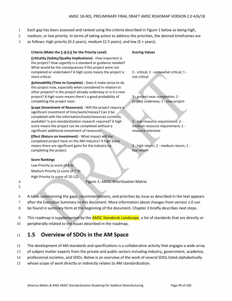
AMSC 18-001, PRELIMINARY FINAL DRAFT AMSC ROADMAP VERSION 2.0 4/6/18
America Makes & ANSI AMSC Standardization Roadmap for Additive Manufacturing Page 49 of 260
Each gap has been assessed and ranked using the criteria described in Figure 1 below as being high, 1
medium, or low priority. In terms of taking action to address the priorities, the desired timeframes are 2
as follows: high priority (0-2 years), medium (2-5 years), and low (5 + years). 3
Criteria (Make the C-A-S-E for the Priority Level) Scoring Values
Criticality (Safety/Quality Implications) - How important is the project? How urgently is a standard or guidance needed? What would be the consequences if the project were not completed or undertaken? A high score means the project is more critical.
3 - critical; 2 - somewhat critical; 1 - not critical
Achievability (Time to Complete) - Does it make sense to do this project now, especially when considered in relation to other projects? Is the project already underway or is it a new project? A high score means there's a good probability of completing the project soon.
3 - project near completion; 2 - project underway; 1 - new project
Scope (Investment of Resources) - Will the project require a significant investment of time/work/money? Can it be completed with the information/tools/resources currently available? Is pre-standardization research required? A high score means the project can be completed without a significant additional investment of resources.
3 - low resource requirement; 2 - medium resource requirement; 1 - resource intensive
Effect (Return on Investment) - What impact will the completed project have on the AM industry? A high score means there are significant gains for the industry by completing the project.
3 - high return; 2 - medium return; 1 - low return
Score Rankings Low Priority (a score of 4-6) Medium Priority (a score of 7-9) High Priority (a score of 10-12)
Figure 1: AMSC Prioritization Matrix 4
5
A table summarizing the gaps, recommendations, and priorities by issue as described in the text appears 6
after the Executive Summary to this document. More information about changes from version 1.0 can 7
be found in summary form at the beginning of the document. Chapter 3 briefly describes next steps. 8
This roadmap is supplemented by the AMSC Standards Landscape, a list of standards that are directly or 9
peripherally related to the issues described in the roadmap. 10
1.5 Overview of SDOs in the AM Space 11
The development of AM standards and specifications is a collaborative activity that engages a wide array 12
of subject matter experts from the private and public sectors including industry, government, academia, 13
professional societies, and SDOs. Below is an overview of the work of several SDOs listed alphabetically 14
whose scope of work directly or indirectly relates to AM standardization. 15
AMSC 18-001, PRELIMINARY FINAL DRAFT AMSC ROADMAP VERSION 2.0 4/6/18
America Makes & ANSI AMSC Standardization Roadmap for Additive Manufacturing Page 50 of 260
1.5.1 Association for the Advancement of Medical Instrumentation (AAMI) 1
The Association for the Advancement of Medical Instrumentation (AAMI) is the leading developer of 2
standards for medical devices globally. In addition to American National Standards, AAMI publishes 3
guidance documents (Technical Information Reports) that address medical device production and use. 4
AAMI also administers 17 U.S. Technical Advisory Groups (TAGs) and 10 international secretariats for 5
International Organization for Standardization (ISO) or International Electrotechnical Commission (IEC) 6
committees or subcommittees addressing medical technology. 7
Over the decades AAMI has produced a large body of standards that govern aspects of the design and 8
manufacture of medical devices (quality systems, risk management, materials testing, process control, 9
sterilization, residual management, etc.). AAMI standards focus on enhancing the safety and efficacy of 10
medical devices and are widely referenced or recognized by regulatory frameworks around the world. 11
The distinct nature of additive manufacturing and the ability to create unique or customized devices add 12
challenges to ensuring the safety and efficacy of products. AAMI is very interested in determining what 13
guidance might be developed for applying existing standards to additive manufacturing, as well as what 14
new standards or controls may be necessary. 15
1.5.2 American Society of Mechanical Engineers (ASME) 16
ASME Committee Efforts to Address Additive Manufacturing 17
18
ASME Y14 Subcommittee 46 Product Definition for Additive Manufacturing 19
Committee Webpage: 20
https://cstools.asme.org/csconnect/CommitteePages.cfm?Committee=100749850 21
Charter: To develop and standardize systems and indications to promote uniform practices for product 22
definition for Additive Manufacturing (AM); to create a broadly accepted standard that incorporates, 23
expands, or refines international practices and symbology to enable AM product definition data sets to 24
be created, interpreted, and consumed on a global basis. 25
Document: ASME Y14.46-2017, Product Definition for Additive Manufacturing [Draft Standard for Trial 26
Use] 27
This document addresses Product Definition Requirements that are specific to Additive Manufacturing. 28
This standard covers definitions of terms and features unique to additive manufacturing technologies 29
with recommendations for their uniform specification in product definition data sets and in related 30
documents. 31
ASME Y14 Subcommittee 41.1 on 3D Model Data Organization Schema 32
Committee Webpage: 33
https://cstools.asme.org/csconnect/CommitteePages.cfm?Committee=100688394 34
AMSC 18-001, PRELIMINARY FINAL DRAFT AMSC ROADMAP VERSION 2.0 4/6/18
America Makes & ANSI AMSC Standardization Roadmap for Additive Manufacturing Page 51 of 260
Document: ASME Y14.47-201x, Model Organization Schema Practices 1
This standard establishes a schema for organizing 3D model and other associated information within the 2
context of a digital product definition data set for the purpose of conveying a product definition that 3
enables a Model-Based Enterprise (MBE). This standard contains no requirements pertaining to drawing 4
graphic sheets. The schema defines a common practice to improve design productivity and to deliver 5
consistent data content and structure to consumers of the data. This particular schema need not be 6
followed verbatim as long as the producer of the digital product definition data provides a map of the 7
content of the 3D model into the schema. 8
ASME Y14 Subcommittee 48 on Universal Direction and Load Indicators 9
Committee Webpage: 10
https://cstools.asme.org/csconnect/CommitteePages.cfm?Committee=102068063 11
Charter: Standardization of methods to unambiguously define and specify directions, directional 12
requirements, loads, and loading requirements in product definition data sets. 13
This standard provides symbolic methods to unambiguously delineate directions, directional 14
requirements, loads, and loading requirements in product definition data. It will define standard 15
methods of specifying linear and non-linear directions, the direction of gravity, point loads, pressure 16
differentials, and other types of directional and loading requirements, and the relationships of directions 17
and loads to datum reference frames associated to products. 18
ASME B46 Project Team on Additive Manufacturing 19
Committee Webpage: 20
https://cstools.asme.org/csconnect/CommitteePages.cfm?Committee=102019836 21
This document explains how to find parameters that can describe the topography of AM parts so that 22
they can correlate with and discriminate between processing and performance parameters. 23
Specification of surface topographies should reflect their influence on performance and be capable of 24
correlating with process parameters. The surfaces created by additive manufacturing are distinctly 25
different from those created by traditional methods. What has been learned about specifying 26
topographies for processing and performance with traditional manufacturing is of little help for 27
recommending surface texture characterization parameters for additive manufacturing that can be 28
valuable for product and process design. 29
ASME V&V Subcommittee 50, Verification and Validation of Computational Modeling for Advanced 30
Manufacturing 31
Committee Webpage: 32
https://cstools.asme.org/csconnect/CommitteePages.cfm?Committee=101978604 33
AMSC 18-001, PRELIMINARY FINAL DRAFT AMSC ROADMAP VERSION 2.0 4/6/18
America Makes & ANSI AMSC Standardization Roadmap for Additive Manufacturing Page 52 of 260
Charter: To provide procedures for verification, validation, and uncertainty quantification in modeling 1
and computational simulation for advanced manufacturing. 2
V&V for Additive Manufacturing is a focused topic area to explore V&V issues in a context. It is on a scale 3
that this nascent group can engage with and make progress on. There is real opportunity to potentially 4
engage with the software industry that is creating the first AM commercial models and help define best 5
practices based on lessons learned in prior ASME V&V efforts. 6
ASME New Committee on Advanced Monitoring, Diagnostic, and Prognostic Technologies for 7
Manufacturing 8
ASME is in the process of establishing a new committee to address advanced monitoring, diagnostic, and 9
prognostic technologies for manufacturing. 10
These guidelines would allow manufacturers to determine: 1) the most appropriate data to collect from 11
a manufacturing operation; 2) an efficient strategy to collect the identified data; 3) the recommended 12
approach to organize, store, and contextualize the data; 4) the ideal analyses to apply to the data; 5) the 13
V&V of these analyses; and 6) the dissemination of these results across the manufacturing facility to 14
promote more effective decision-making with respect to updating control and maintenance strategies. 15
ASME Committee Efforts Relevant to Additive Manufacturing 16
17
ASME Y14 Subcommittee 41, Digital Product Definition Data Practices 18
Committee Webpage: 19
https://cstools.asme.org/csconnect/CommitteePages.cfm?Committee=C64045910 20
Document: ASME Y14.41-2012, Digital Product Definition Data Practices 21
This standard establishes requirements and references documents applicable to the preparation and 22
revision of digital product definition data, hereafter referred to as data sets. This standard defines 23
exceptions and additional requirements to existing ASME standards for using product definition digital 24
data sets or drawing graphic sheets in digital format, hereafter referred to as drawing graphic sheets. 25
ASME B89 Project Team 4.23, CT Measuring Machines 26
Document: ASME B89.4.23-201x, X-ray Computed Tomography (CT) Performance Evaluation Standard 27
This standard specifies the dimensional measurement accuracy of industrial X-ray computed 28
tomography (CT) systems for point-to-point length measurements of homogeneous materials. Medical 29
CT instruments are outside the scope of this standard. This standard is applicable to dimensional 30
measurements made at the surface of the workpiece, i.e., at the workpiece material – air interface, 31
including those of internal cavities. The evaluation of workpieces composed of multiple materials or of 32
“density gradient” measurements, e.g., gradual density variations within the material, is outside the 33
scope of this standard. 34
ASME Y14.5, Dimensioning and Tolerancing 35
AMSC 18-001, PRELIMINARY FINAL DRAFT AMSC ROADMAP VERSION 2.0 4/6/18
America Makes & ANSI AMSC Standardization Roadmap for Additive Manufacturing Page 53 of 260
Committee Webpage: 1
https://cstools.asme.org/csconnect/CommitteePages.cfm?Committee=C64041000 2
Document: ASME Y14.5-2009, Dimensioning and Tolerancing 3
This standard establishes rules, definition, requirements, defaults and recommended practices for 4
stating and interpreting dimensioning, tolerancing, and related requirements for use on engineering 5
drawings, models defined in digital data files and in related documents. 6
Y14.5 provides essential geometric dimensioning and tolerancing (GD&T) language for communicating 7
design intent, ensuring that parts from technical drawings have the desired form, fit, function and 8
interchangeability. 9
1.5.3 ASTM International (ASTM) 10
ASTM International is a globally recognized leader in the development and delivery of voluntary 11
consensus standards. Today, over 13,000 ASTM standards are used around the world to improve 12
product quality, enhance health and safety, strengthen market access and trade, and build consumer 13
confidence. ASTM’s leadership in international standards development is driven by the contributions of 14
its members: more than 30,000 of the world’s top technical experts and business professionals 15
representing 140 countries. Working in an open and transparent process and using ASTM’s advanced IT 16
infrastructure, ASTM members create the test methods, specifications, classifications, guides and 17
practices that support industries and governments worldwide. 18
Through more than 140 technical standards-writing committees, ASTM serves a broad range of 19
industries: metals, construction, petroleum, consumer products and many more. When new industries 20
— like nanotechnology, additive manufacturing and industrial biotechnology — look to advance the 21
growth of cutting-edge technologies through standardization, many of them come to ASTM 22
International. It is notable that ASTM test methods are required to have statements addressing 23
precision and bias, statistically determined from round robin studies. 24
ASTM International Committee F42 on Additive Manufacturing Technologies was organized by industry 25
in 2009. At present, the committee consists of 625+ individuals and organizations representing 27 26
countries. The committee is dedicated to the promotion of knowledge, stimulation of research, and 27
implementation of technology through the development of standards for additive manufacturing 28
technologies. The work of the committee is coordinated with other ASTM technical committees and 29
other national and international organizations having mutual or related interests. 30
The work program of F42 is significant, having approved 22 standards at the time of writing this 31
roadmap section, with an additional 17 work items in various stages of development - 32
https://www.astm.org/COMMIT/SUBCOMMIT/F42.htm. All standards fall under the F42 subcommittee 33
structure of: 34
AMSC 18-001, PRELIMINARY FINAL DRAFT AMSC ROADMAP VERSION 2.0 4/6/18
America Makes & ANSI AMSC Standardization Roadmap for Additive Manufacturing Page 54 of 260
F42.01 Test Methods 1
F42.04 Design 2
F42.05 Materials and Processes 3
F42.06 Environment, Health, and Safety 4
F42.91 Terminology 5
F42.95 U.S. TAG to ISO/TC 261 6
Additional information about ASTM F42’s joint work program with ISO/TC 261 can be found at the end 7
of this section and in section 1.5.7. 8
Other ASTM Technical Committees identified by the AMSC as having work relevant to AM include: 9
B09: ASTM International Committee B09 on Metal Powder & Metal Powder Products has jurisdiction 10
over standards on metal powder characterization such as flow characteristics, particle size distribution, 11
sampling and densities. Many AM parts are made using metal powders specifically manufactured for this 12
purpose. For a listing of the standards under the jurisdiction of B09 and its sub-committees, visit: 13
http://www.astm.org/COMMIT/SUBCOMMIT/B09.htm. 14
E04: ASTM International Committee E04 on Metallography has jurisdiction over the development of 15
standard methods for the preparation of specimens for, but not limited to: metallographic procedures; 16
photomicrography; microhardness testing; grain size measurements; determining inclusion content of 17
metals; quantitative metallography; X-ray metallography including diffraction analysis, texture and 18
orientation determinations, residual stress measurements, and microradiography; electron 19
metallography utilizing transmission electron microscopy, scanning electron microscopy, electron 20
diffraction, and microprobe analysis; field ion microscopy; and ion microprobe and Auger analysis. The 21
Committee also works with the International Center for Powder Diffraction Data, Joint Committee on 22
Powder Diffraction Standards (JCPDS), which Committee E04 sponsors. Additional information for 23
Committee E04, along with a list of current and proposed standards, is available at: 24
http://www.astm.org/COMMITTEE/E04.htm 25
E07: ASTM International Subcommittee E07.10 on Specialized NDT Methods, housed under Committee 26
E07 on Nondestructive Testing, is concerned with the development of nondestructive testing by 27
methods of emerging and specialized technologies, and as such, this subcommittee has taken on the 28
activities of nondestructive testing for additively manufactured parts. A list of standards and work items 29
found under Subcommittee E07.10 can be found at: 30
https://www.astm.org/COMMIT/SUBCOMMIT/E0710.htm. The current focus of the subcommittee is on 31
ASTM WK47031, New Guide for Nondestructive Testing of Additive Manufactured Metal Parts Used in 32
Aerospace Applications. Information on the scope of this work item can be found at: 33
https://www.astm.org/DATABASE.CART/WORKITEMS/WK47031.htm. The subcommittee has also 34
developed an internal roadmap in expectation of the future development of nondestructive testing 35
standards in support of additively manufactured parts. 36
E08: Fatigue and Fracture develops standards that focus on the fatigue and fracture of materials and 37
structures that are manufactured from conventional manufacturing technologies. The emergence of 38
AMSC 18-001, PRELIMINARY FINAL DRAFT AMSC ROADMAP VERSION 2.0 4/6/18
America Makes & ANSI AMSC Standardization Roadmap for Additive Manufacturing Page 55 of 260
additive manufacturing has the committee looking at its current fatigue testing standards to determine 1
if they need to be modified if test specimens are built using AM. There are many details involved in 2
making an AM build that will affect fatigue resistance, and these details need to be brought into the 3
current standards. Standardization is a key and vital element to establish trust in components fabricated 4
using AM, and many industries are rapidly moving forward with the use of AM. Subcommittees E08.05 5
on Cyclic Deformation and Fatigue Crack Formation and E08.06 on Crack Growth Behavior are leading 6
the effort in Committee E08 as they pursue standards activities in AM. More information is available at: 7
https://www.astm.org/COMMIT/SUBCOMMIT/E08.htm 8
9
E28: ASTM International Committee E28 on Mechanical Testing focuses on the development of 10
standards that involve the measurement of mechanical properties typically in metallic materials. The 11
various E28 subcommittees address ductility, flexure, uniaxial testing, indentation hardness, and impact 12
testing. E28 also addresses the calibration of mechanical testing machines and instruments used to 13
determine mechanical properties. These standards can be used to evaluate the mechanical properties of 14
additively manufactured materials, and are also used to compare a traditional material versus an 15
additively manufactured material. Information on all of the E28 subcommittees and their standards can 16
be found at: http://www.astm.org/COMMIT/SUBCOMMIT/E28.htm. 17
E29: ASTM International Committee E29 on Particle and Spray Characterization has jurisdiction over 18
standards used for characterizing solid and liquid particles and for the apparatus and techniques 19
required for such purposes. E29 relates to additive manufacturing in the sense that many AM machines 20
spray particles during the manufacturing process. For a listing of the standards under the jurisdiction of 21
E29 and its sub-committees, visit: http://www.astm.org/COMMITTEE/E29.htm. 22
F04.12: Subcommittee on Metallurgical Materials, housed under Committee F04 on Medical and 23
Surgical Materials and Devices, is concerned with defining and determining the properties and 24
characteristics of metallurgical materials in order to develop standard specifications, test methods, 25
classifications and performance requirements for medical and surgical materials and devices. A list of 26
standards and work items found under Subcommittee F04.12 can be found at: 27
https://www.astm.org/COMMIT/SUBCOMMIT/F0412.htm. F04.12 maintains liaison with Committee 28
F42. 29
Partner Standards Developing Organization (PSDO) Agreement between ASTM International and ISO 30
Signed in 2011 by the ASTM president the ISO Secretary General 31
(http://www.astmnewsroom.org/default.aspx?pageid=3108), this agreement is an enabler of jointly 32
developed standards in the AM space between ASTM F42 on Additive Manufacturing Technologies and 33
ISO TC261 on Additive Manufacturing. 34
The PSDO agreement speaks to: 35
36
fast tracking the adoption process of an ASTM International standard as an ISO final draft 37
international standard; 38
formal adoption of a published ISO standard by ASTM International; 39
AMSC 18-001, PRELIMINARY FINAL DRAFT AMSC ROADMAP VERSION 2.0 4/6/18
America Makes & ANSI AMSC Standardization Roadmap for Additive Manufacturing Page 56 of 260
maintenance of published standards; and 1
publication, copyright, and commercial arrangements. 2
At the time of writing of this roadmap section, the PSDO had produced 5 joint ISO/ASTM standards 3
(below), with additional joint standards projects under development. 4
1. ISO/ASTM52900-15, Standard Terminology for Additive Manufacturing – General Principles – 5
Terminology 6
2. ISO/ASTM52901 – 17, Standard Guide for Additive Manufacturing – General Principles – 7
Requirements for Purchased AM Parts 8
3. ISO/ASTM52915-16, Standard Specification for Additive Manufacturing File Format (AMF) 9
Version 1.2 10
4. ISO/ASTM52921-13, Standard Terminology for Additive Manufacturing-Coordinate Systems and 11
Test Methodologies 12
5. ISO/ASTM 52911-1, Additive manufacturing – Technical Design Guideline for Powder Bed Fusion 13
–Part 1: Laser-based Powder Bed Fusion of Metals 14
6. ISO/ASTM 52911-2, Additive manufacturing – Technical Design Guideline for Powder Bed Fusion 15
– Part 2: Laser-based Powder Bed Fusion of Polymers 16
The ISO TC261 work program contains the 6 joint standards (above), 3 additional standards, and 16 17
other work items in various stages of development. See: 18
http://www.iso.org/iso/home/standards_development/list_of_iso_technical_committees/iso_technical19
_committee.htm?commid=629086. 20
On October 6, 2016, ASTM F42 and ISO/TC 261 announced a new standards development framework 21
(Figure 2) that they agreed to under which standards can be developed at three levels: 22
23
general standards (e.g., concepts, common requirements, guides, safety); 24
standards for broad categories of materials (e.g., metal powders) or processes (e.g., powder bed 25
fusion); and 26
specialized standards for a specific material (e.g., aluminum alloy powders), process (e.g., 27
material extrusion with ABS), or application (e.g., aerospace, medical, automotive). 28
The announcement noted that the structure does not confine the scope of work for any standards 29
organization but provides a framework in which the majority of standards needs can be met. A 30
companion guidance document is also being developed to accompany this structure. 31
32
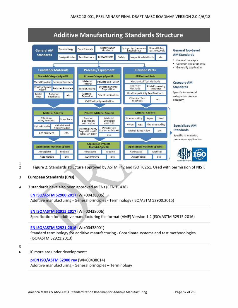
AMSC 18-001, PRELIMINARY FINAL DRAFT AMSC ROADMAP VERSION 2.0 4/6/18
America Makes & ANSI AMSC Standardization Roadmap for Additive Manufacturing Page 57 of 260
1 Figure 2: Standards structure approved by ASTM F42 and ISO TC261. Used with permission of NIST. 2
European Standards (ENs) 3
3 standards have also been approved as ENs (CEN TC438) 4
EN ISO/ASTM 52900:2017 (WI=00438005) Additive manufacturing - General principles - Terminology (ISO/ASTM 52900:2015)
EN ISO/ASTM 52915:2017 (WI=00438006) Specification for additive manufacturing file format (AMF) Version 1.2 (ISO/ASTM 52915:2016)
EN ISO/ASTM 52921:2016 (WI=00438001) Standard terminology for additive manufacturing - Coordinate systems and test methodologies (ISO/ASTM 52921:2013)
5
10 more are under development: 6
prEN ISO/ASTM 52900 rev (WI=00438014) Additive manufacturing - General principles – Terminology
AMSC 18-001, PRELIMINARY FINAL DRAFT AMSC ROADMAP VERSION 2.0 4/6/18
America Makes & ANSI AMSC Standardization Roadmap for Additive Manufacturing Page 58 of 260
prEN ISO/ASTM 52901 (WI=00438017) Additive manufacturing - General principles - Requirements for purchased AM parts (ISO/ASTM 52901:2017)
prEN ISO/ASTM 52902 (WI=00438007) Additive manufacturing -- General principles -- Standard test artifacts
prEN ISO/ASTM 52903-2 (WI=00438008) Additive Manufacturing - Standard Specification for Material Extrusion Based Additive Manufacturing of Plastic Materials - Part 2 process – equipment
prEN ISO/ASTM 52903-3 (WI=00438010) Additive Manufacturing -- Standard Specification for Material Extrusion Based Additive Manufacturing of Plastic Materials -- Part 3: Final parts
prEN ISO/ASTM 52905 (WI=00438009) Additive manufacturing -- General principles -- Nondestructive testing of additive manufactured products
prEN ISO/ASTM 52907 (WI=00438013) Additive manufacturing - Technical specifications on metal powders
prEN ISO/ASTM 52911-1 (WI=00438012) Additive manufacturing - Technical Design Guideline for Powder Bed Fusion - Part 1: Laser-based Powder Bed Fusion of metals (ISO/ASTM DIS 52911-1:2017)
prEN ISO/ASTM 52911-2 (WI=00438011) Additive manufacturing - Technical Design Guideline for Powder Bed Fusion - Part 2: Laser-based Powder Bed Fusion of Polymers (ISO/ASTM DIS 52911-2:2017)
prEN ISO/ASTM 52915 rev (WI=00438015) Specification for additive manufacturing file format (AMF) Version 1.2
1
Additive Manufacturing Center of Excellence (CoE) Partnership with EWI and Auburn University-NASA 2
ASTM International, with its partners EWI and jointly Auburn University-NASA, has established an 3
Additive Manufacturing Center of Excellence (CoE) to facilitate collaboration and coordination between 4
government, academia, and industry to advance AM standardization and expand ASTM and its partners’ 5
capabilities. The CoE’s mission is to bridge standards development with R&D to better enable efficient 6
development of standards, education and training, certification, and proficiency testing programs. 7
1.5.4 American Welding Society (AWS) 8
The American Welding Society (AWS) formed the D20 committee on additive manufacturing (AM) in 9
2013 to develop a standard that would integrate requirements for the additive manufacturing of metal 10
AMSC 18-001, PRELIMINARY FINAL DRAFT AMSC ROADMAP VERSION 2.0 4/6/18
America Makes & ANSI AMSC Standardization Roadmap for Additive Manufacturing Page 59 of 260
components. The AWS D20 committee, which consists of volunteers working in various AM-related 1
fields, is in the process of completing a draft of the AWS D20.1, Standard for Fabrication of Metal 2
Components using Additive Manufacturing. AWS D20.1 will be a comprehensive document that 3
identifies requirements related to AM component design, procedure qualification, machine operator 4
performance qualification, fabrication, and inspection. The draft AWS D20.1 standard implements a 5
graded approach to qualification and inspection, with requirements determined by the criticality of the 6
component. The scope of the draft AWS D20.1 standard includes both powder bed fusion (PBF) and 7
directed energy deposition (DED) metal AM processes. The standard is anticipated to be available in 8
2019. 9
The AWS D20 committee currently has three active task groups: Qualification, Fabrication, and 10
Inspection. The Qualification Task Group is working on finalizing the AWS D20.1 clauses on AM 11
procedure qualification and machine operator performance qualification. The AM procedure 12
qualification clause contains requirements to demonstrate the capability of an AM procedure to 13
produce a component that meets acceptance requirements, including qualification test piece design, 14
testing, and acceptance; procedure qualification variables for each AM process covered by AWS D20.1; 15
and requalification requirements based on changes to procedure qualification variables. The 16
performance qualification clause contains requirements intended to ensure that AM machine operators 17
are capable of repeatedly fabricating acceptable AM components. This clause will include requirements 18
related to topics such as AM machine operator training, written and practical examinations, and the 19
demonstration of an acceptable build. 20
The Fabrication Task Group of the AWS D20 committee is working on the clause that will contain 21
requirements designed to ensure the successful fabrication of AM components. Examples of topics 22
covered by this clause include requirements related to feedstock storage, cleanliness, equipment 23
calibration and testing, use of qualified procedures and personnel, witness specimens, interpass 24
temperature control, build interruptions, part identification, post-build processing, and repair. 25
The Inspection Task Group is working to draft inspection requirements for AM components based on 26
component classification. Due to the limitations of volumetric inspection techniques to measure 27
discontinuities for typical AM component geometries, this task group is considering multiple potential 28
options for inspection of AM components. These options may include the demonstration that 29
acceptable discontinuity size requirements are met through volumetric inspection of the component 30
(similar to the inspection requirements of AWS D17.1/D17.1M:2010-AMD1, Specification for Fusion 31
Welding for Aerospace Applications - AMD), characterization of discontinuities in AM procedure 32
qualification mechanical test specimens and verification that the discontinuities in a prototypic 33
component build are no worse, and the use of proof tests based on individual component functional 34
requirements. 35
Since metal AM essentially involves the fabrication of components from weld metal, the AWS D20 36
committee considers that many existing AWS documents and standards are relevant to the 37
development of requirements for metal AM components. These include AWS B2.1/B2.1M:2014, 38
Specification for Welding Procedure and Performance Qualification; AWS D17.1/D17.1M:2010-AMD1, 39
AMSC 18-001, PRELIMINARY FINAL DRAFT AMSC ROADMAP VERSION 2.0 4/6/18
America Makes & ANSI AMSC Standardization Roadmap for Additive Manufacturing Page 60 of 260
Specification for Fusion Welding for Aerospace Applications - AMD); and various other materials, 1
inspection, and process documents. AWS D20 also keeps up with related international work. 2
At the time of writing of this roadmap section, further related work was getting underway in ISO/TC 3
44/SC 14/WG 1, Additive Manufacturing in Aerospace, though this WG did not have any work items. 4
There have also been activities in the International Institute of Welding, but no standards projects had 5
been requested. 6
1.5.5 Institute for Electrical and Electronics Engineers (IEEE) 7
IEEE is the world’s largest technical professional organization dedicated to advancing technology for the 8
benefit of humanity. Through its highly cited publications, conferences, technology standards, and 9
professional and educational activities, IEEE is the trusted voice in a wide variety of areas ranging from 10
aerospace systems, computers, and telecommunications to biomedical engineering, electric power, and 11
consumer electronics. Learn more at http://www.ieee.org. 12
The IEEE Standards Association (IEEE-SA), a globally recognized standards-setting body within IEEE, 13
develops consensus standards through an open process that engages industry and brings together a 14
broad stakeholder community. IEEE standards set specifications and best practices based on current 15
scientific and technological knowledge. The IEEE-SA has a portfolio of over 1,200 active standards and 16
over 650 standards under development. For more information visit http://standards.ieee.org. 17
Below are IEEE projects sponsored or jointly sponsored by the IEEE Computer/Standards Activity Board, 18
the IEEE Consumer Electronics Society/Standards Board, and the IEEE Engineering, Medicine and Biology 19
Society/Standards Committee that may be relevant to additive manufacturing. 20
The IEEE 3333 series is a multi-part standard, part one of which is published and parts 2-5 are in 21
development. 22
Sponsored by: IEEE Computer Society/Standards Activity Board 23
Working Group: 3D Based Medical Application Working Group (C/SAB/3333-2_WG) 24
Chaired by: Young Lae Moon (Located in Korea) 25
Standard: IEEE 3333.2.1-2015 (Completed) 26
Title: IEEE Recommended Practice for Three-Dimensional (3D) Medical Modelling 27
Scope: This standard includes volume rendering and surface rendering techniques for three-28
dimensional (3D) reconstruction from two-dimensional medical images. Also, it contains a texturing 29
method of 3D medical data for the realistic visualization. 30
Standardization related to medical services includes medical equipment utilizing two-dimensional 31
images, three-dimensional medical data, and contents for diagnosis and treatment. Standardization 32
of medical contents, software, and hardware will enhance safety, economy, and quality of the 3D 33
medical services. 34
Purpose: Medical images from hospitals consist of a 2D data set, providing information on the 35
human body as sectioned slices. The human body has a morphological structure in 3D space. 36
Therefore, to recognize human organs, a 3D reconstruction process is necessary to be performed 37
AMSC 18-001, PRELIMINARY FINAL DRAFT AMSC ROADMAP VERSION 2.0 4/6/18
America Makes & ANSI AMSC Standardization Roadmap for Additive Manufacturing Page 61 of 260
using 2D slice. After this, its precise position and shape can be identified. 1
Medical 3D volume images are based on unprocessed 3D medical data, which contains a variety of 2
medical information. It determines guidelines, standards of medical 3D technology, and 3D volume 3
images’ safety and quality. Additionally, these standards describe generation and practical use of 4
medical 3D modeling for diagnostics and therapeutic applications. 5
6
Project: IEEE P3333.2.2 7
Title: Standard for Three-Dimensional (3D) Medical Visualization 8
Scope: This standard focuses on the demands arising when scientific results in the field of 3D 9
medical visualization are applied for the construction of a software system. It is targeted to aid the 10
clinical work of medical professionals. 11
This standard includes visualization techniques by the automated medical shape detection and 12
reconstruction of three-dimensional (3D) models from two-dimensional medical images. Also it 13
contains texturing of three-dimensional medical data for the intuitive visualization. 14
Purpose: Medical 3D data acquisition devices are increasingly available and able to provide accurate 15
spatial information for the human body. Even though nowadays hardware capabilities and rendering 16
algorithms have improved to the point that 3D visualizations can be rapidly obtained from acquired 17
data, 3D reconstructions are not routinely used in most hospitals. This is because physicians are 18
traditionally trained to gather information from 2D image slices, and because 3D volumetric images 19
displayed on traditional devices are often of questionable value because of ambiguities in their 20
interpretations. Therefore, this standard provides routine visualization techniques for three-21
dimensional medical images, so that medical images can be visualized from routine processes. 22
Project: IEEE P3333.2.3 23
Title: Standard for Three-Dimensional (3D) Medical Data Management 24
Scope: This standard includes medical 2D and 3D data management such as storage, compression 25
for transfer, regulation for wired or wireless transfer, and search engine development for data 26
retrieval. 27
Purpose: The purpose of this standard is to allow a standardized sharing method of 2D and 3D data 28
with security for human-care managers and medical service providers to support the decision-29
making process. 30
Project: IEEE P3333.2.4 31
Title: Standard for Three-Dimensional (3D) Medical Simulation 32
Scope: This standard discusses the simulation of the movement of joints and subsequent changes of 33
skin, muscle, and neighboring structures. It defines joint range of motion, movement, and structure 34
of skeleton, for rigging work. 35
Purpose: The purpose of this document is the standardization of three-dimensional medical 36
simulations, which will help device development and related research. 37
Project: IEEE P3333.2.5 38
AMSC 18-001, PRELIMINARY FINAL DRAFT AMSC ROADMAP VERSION 2.0 4/6/18
America Makes & ANSI AMSC Standardization Roadmap for Additive Manufacturing Page 62 of 260
Title: Standard for Bio-CAD File Format for Medical Three-Dimensional (3D) Printing 1
Scope: This standard defines the Bio-CAD format for three-dimensional (3D) printing based on 2
sectional scan image data containing surface and volumetric information. Standardization is related 3
to medical 3D printing services, including anatomic, pathologic models, and medical instrument 4
printing based on two-dimensional images, three-dimensional medical data, and other medical data. 5
Purpose: To establish the standardization of an accurate and optimized Bio-CAD file format system 6
for medical 3D printing. 7
Status of Project: New project and in draft development 8
Sponsored by: IEEE Consumer Electronics Society/Standards Committee 9
Working Group: Consumer 3D Printing Working Group (CES/SC/C3DP) 10
Chaired by: Yu Yuan (Located in China) 11
Project: IEEE P3030 12
Title: Standard for Consumer 3D Printing: Overview and Architecture 13
Scope: This standard defines an architectural framework for consumer 3D printing, including 14
descriptions of various domains (systems, services, devices, participants, etc.), definitions of domain 15
abstractions, and identification of commonalities between different domains. The architectural 16
framework for consumer 3D printing provides a reference model that defines relationships among 17
various domains and common architectural elements. It also provides a blueprint for data 18
abstraction, quality, protection, and safety. 19
Status of Project: New project and in draft development 20
Other Info: IEEE P3030 is focused on standards development to establish quality metrics and 21
accuracy grades so that printed materials at the consumer level can be assembled faultlessly, while 22
also addressing issues related to privacy, security, and control measures. 23
Sponsored by: IEEE Computer Society/Test Technology (C/TT) 24
Working Group: 3D-Test Working Group (C/TT/3DT-WG) 25
Chaired by: Erik Jan Marinissen (Located in Belgium) 26
Project: IEEE P1838 27
Title: Standard for Test Access Architecture for Three-Dimensional Stacked Integrated Circuits 28
Scope: The proposed standard is a 'die-centric' standard; it applies to a die that is intended to be 29
part of a multi-die stack. The proposed standard defines die-level features that, when compliant dies 30
are brought together in a stack, comprise a stack-level architecture. This enables transportation of 31
control and data signals for the test of: (1) intra-die circuitry and (2) inter-die interconnects, in both 32
(a) pre-stacking and (b) post-stacking situations, the latter for both partial and complete stacks in 33
pre-packaging, post-packaging, and board-level situations. The primary focus of inter-die 34
interconnect technology addressed by this standard is through-silicon vias (TSVs); however, this 35
does not preclude its use with other interconnect technologies such as wire-bonding. 36
The standard will consist of two related items. 37
1. 3D Test Wrapper Hardware – On-die hardware features that enable transportation of test (control 38
and data) signals in pre-stacking and post-stacking (turn mode or elevator mode) configurations. 39
AMSC 18-001, PRELIMINARY FINAL DRAFT AMSC ROADMAP VERSION 2.0 4/6/18
America Makes & ANSI AMSC Standardization Roadmap for Additive Manufacturing Page 63 of 260
2. Description + Description Language – A description of the test wrapper features in a standardized 1
human- and computer-readable language. This description should allow usage of the die within a 2
multi-die stack for test and test access purposes. 3
The proposed standard does not mandate specific defect or fault models, test generation methods, 4
or die-internal design-for-test, but instead focuses on generic test access to and between dies in a 5
multi-die stack. The proposed standard is based on and works with digital scan-based test access 6
and should leverage existing test access ports (such as based on IEEE Std 1149.x) and on-chip design-7
for-test (such as IEEE 1500-2005) and design-for-debug (IEEE P1687) infrastructure wherever 8
applicable and appropriate. 9
The proposed standard is 'die-centric' and hence does not aim at 'stack/product-centric' challenges, 10
solutions, and standards, such as the inclusion of boundary scan features for board-level 11
interconnect testing. However, the proposed standard should not prohibit the application of such 12
solutions. 13
Status of Project: New project and in draft development 14
IEEE P1838 public website: http://grouper.ieee.org/groups/3Dtest 15
Other info: There is a list of published status reports located in 16
http://grouper.ieee.org/groups/3Dtest/#StatusReports. 17
Sponsored by: IEEE Consumer Electronics Society/Standards Committee 18
Working Group: 3DBP - 3D Body Processing 19
Chaired by: Luciano Oviedo 20
Project: IEEE P3141 21
Title: Standard for 3D Body Processing 22
Scope: This standard addresses the fundamental attributes that contribute to 3D body processing 23
quality of experiences, as well as identifying and analyzing existing metrics and other useful 24
information relating to these attributes. It defines a standardized suite of objective and subjective 25
methods, tools and frameworks for assessing 3D body processing quality of experience attributes, 26
and it specifies methods, tools and frameworks to facilitate standards-based interoperability, 27
communication, security and comparison among 3D body processing technologies such as 3D/depth 28
sensors, scanners, digitization, simulation and modeling, analytics and animation/visualization for 29
solution providers as well as for consumer facing companies such as in retail, health/wellness, 30
sports/athletics, medical industries. 31
Purpose: 3D body processing technologies are emerging as the next wave for how people interact 32
and engage in a range of semi-to-fully immersive experiences to, for example, shop, play and learn. 33
However, due to market and technology fragmentation, there is a lack of agreement from across the 34
ecosystem for how to align and deliver on quality of experiences as well as how to cope with gaps in 35
interoperability, communication and security. This standard aims to establish a uniform means for 36
deliberately designing and implementing immersive experiences by delivering the ability to evaluate 37
the quality of experience for 3D body processing technologies for technology solution providers as 38
well as for industries such as retail, health/wellness, sports/athletics and medical. 39
Status: New Project 40
AMSC 18-001, PRELIMINARY FINAL DRAFT AMSC ROADMAP VERSION 2.0 4/6/18
America Makes & ANSI AMSC Standardization Roadmap for Additive Manufacturing Page 64 of 260
Sponsored by: IEEE Engineering and Biology Society/Standards Committee 1
Working Group: Medical devices with measuring functions (EMB/Stds Com/MDMF) 2
Chaired by: Almir Badnjevic 3
Project: IEEE P2727 4
Title: Standard for General Vocabulary for Conformity Assessment of Medical Devices with 5
Measuring Function 6
Scope: The standard defines commonly-used terms used in the conformity assessment of medical 7
devices with measuring function for legal metrology purposes. 8
Purpose: The purpose is to provide the framework for nomenclature in the field of medical device 9
legal metrology and establish consistency in the use of the terms. 10
Sponsored by: IEEE Engineering and Biology Society/Standards Committee 11
Working Group: Medical Robots Working Group (EMB/Stds Com/MRWG) 12
Chaired by: Jia Zheng 13
Project: IEEE P2730 14
Title: Standard for Classification, Terminologies, and Definitions of Medical Robots 15
Scope: The standard specifies the category, naming, and definition of medical robots. 16
Purpose: The purpose of this standard is to provide the industry a unified classification and 17
definitions on medical robots that industry can leverage. Harmonization of these classification and 18
definitions on medical robots promotes a common framework for the industry in the rapid 19
development and deployment of medical robots the healthcare industry. 20
Sponsored by: IEEE Engineering and Biology Society/Standards Committee 21
Working Group: Intelligence Augmentation for Medical Imaging (EMB/Stds Com/IA Medical Imaging) 22
Chaired by: Moira Schieke 23
Project: IEEE P2673 24
Title: Intelligence Augmentation for Medical Imaging (EMB/Stds Com/IA Medical Imaging) 25
Scope: This standard provides a framework for organization and use of new patient biomedical files 26
containing medical imaging and imaging biomarker information for use in big data cloud-based 27
augmented intelligence systems. In addition, this standard defines 3D digital topological mapping of 28
information and data to human macroanatomy and microanatomy. Included in this standard are 29
requirements to assure compliance with ethical design and value-based design standards to assure 30
(1) patient data security with full access, sharing, and user control of their personal data; and (2) 31
protection of the professional fiduciary relationships between physicians and patients. 32
Purpose: This standard, along with definitions, allows for precise communication among global 33
experts of different domains that includes clinical medical imaging, artificial intelligence, and ethics 34
for augmented intelligence systems that maintain a central role for the medical professional subject 35
matter experts in managing and using image-based information. 3D digital topological mapping of 36
this information and data to human macroanatomy and microanatomy including coordination with 37
existing disease coding across global big data datasets will optimize its use for maximal societal 38
AMSC 18-001, PRELIMINARY FINAL DRAFT AMSC ROADMAP VERSION 2.0 4/6/18
America Makes & ANSI AMSC Standardization Roadmap for Additive Manufacturing Page 65 of 260
benefit. This standard will assure systems integrate human-in-the-loop principles to assure accuracy, 1
reliability, and clinical utility of generated information for safe optimal use in clinical decision-2
making. 3
Printer Working Group: An IEEE-ISTO Federation Member Program 4
The IEEE Industry Standards and Technology Organization (ISTO) was established in January 1999 as a 5
federation of member alliance programs with the aim of supporting accelerated technology standards 6
development and market adoption for industry. A global, 501(c)(6) not-for-profit corporation, ISTO 7
offers a membership infrastructure and legal umbrella under which member alliances and trade groups 8
can stand themselves up as legal operating entities. 9
The Printer Working Group (PWG) is a program of the IEEE-ISTO with members including printer and 10
multi-function device manufacturers, print server developers, operating system providers, print 11
management application developers, and industry experts. Originally founded in 1991 as the Network 12
Printing Alliance, the PWG is chartered to make printers, multi-function devices, and the applications 13
and operating systems supporting them, work better together. 14
The PWG enjoys an open standards development process. Everyone is welcome to contribute to the 15
development of PWG documents and standards, serve as editors, and participate in interoperability 16
tests. Members may additionally serve as officers in the various working groups. Voting members 17
approve the documents and standards for publication and may serve as officers of the PWG. 18
The following Printer Working Group project may be directly relevant to additive manufacturing: 19
Sponsored by: IEEE-ISTO/ Printer Working Group (PWG) 20
Working Group: Internet Printing Protocol (IPP) Workgroup 21
Chaired by: Ira McDonald (High North) and Paul Tykodi (TCS) 22
Project: IPP 3D Printing Extensions 23
Title: PWG 5100.21-2017, IPP 3D Printing Extensions v1.0 (3D) 24
Scope: This specification defines an extension to the Internet Printing Protocol (PWG 5100.12-2015, IPP 25
2.0, 2.1, and 2.2) and IPP Everywhere (PWG 5100.14) that supports printing of physical objects by 26
additive manufacturing devices such as 3D printers. The Internet Printing Protocol (IPP) workgroup has 27
developed a modern, full-featured network printing protocol that is now the ubiquitous industry 28
standard for 2D printing. IPP allows a print client to query a printer for its supported capabilities, 29
features, and parameters to allow the selection of an appropriate printer for each print job. IPP also 30
provides job information prior to, during, and at the end of job processing. 31
Status of Project: Existing project, IPP 3D Printing Extensions v1.0 approved as PWG 5100.21-2017 32
IEEE-ISTO PWG public website: http://www.pwg.org/ 33
There is a list of IEEE-ISTO PWG freely available standards at: 34
http://www.pwg.org/standards.html 35
There is more information about IPP Everywhere at: 36
http://www.pwg.org/ipp/everywhere.html 37
AMSC 18-001, PRELIMINARY FINAL DRAFT AMSC ROADMAP VERSION 2.0 4/6/18
America Makes & ANSI AMSC Standardization Roadmap for Additive Manufacturing Page 66 of 260
There is more information about IPP 3D Printing at: 1
http://www.pwg.org/3d/index.html 2
1.5.6 IPC – the Association Connecting Electronics Industries (IPC) 3
IPC Mission Statement 4
IPC is a global trade association dedicated to furthering the competitive excellence and financial success 5
of its members, who are participants in the electronics industry. In pursuit of these objectives, IPC will 6
devote resources to management improvement and technology enhancement programs, the creation of 7
relevant standards, protection of the environment, and pertinent government relations. IPC encourages 8
the active participation of all its members in these activities and commits to full cooperation with all 9
related organizations. 10
IPC Printed Electronics Committee (D-60) 11
The IPC Printed Electronics Committee (D-60) plans, guides and coordinates printed electronics 12
standards development. These standards focus on electronics that use additive processes as either 13
standalone technologies or as hybrid electronics. 14
Chaired by: Neil Bolding, MacDermid Enthone Electronics Solutions, and Daniel Gamota, Jabil 15
Printed Electronics Design Subcommittee (D-61) 16
This subcommittee is responsible for generating standards related to fundamental design considerations 17
for printed electronics. Design considerations shall include information pertaining to material selection, 18
layout configuration, assembly processes, tests, and in-service use. 19
Chaired by: Alan M Burk, ALMAX, and Richard Snogren, SAIC/Bristlecone LLC 20
21
Project: IPC-2292 22
Title: Design Standard for Printed Electronics on Flexible Substrates 23
Scope: This standard establishes specific requirements for the design of printed electronic applications 24
and their forms of component mounting and interconnecting structures on flexible substrates. Flexible 25
substrates, as pertain to this standard, are materials or devices which have some amount of flexibility or 26
bendability (not rigid) but are not considered to be stretchable (e.g., fabrics, textiles, stretchable 27
polymers, etc.). 28
29
Status of Project: Published 30
Other Info: This group also published IPC-2291, Design Guideline for Printed Electronics in 2013. See 31
Other Published Standards below. 32
Printed Electronics Base Materials/Substrates Subcommittee (D-62) 33
This subcommittee is responsible for generating standards for printed electronics base materials. 34
AMSC 18-001, PRELIMINARY FINAL DRAFT AMSC ROADMAP VERSION 2.0 4/6/18
America Makes & ANSI AMSC Standardization Roadmap for Additive Manufacturing Page 67 of 260
Chaired by: Scott E Gordon, DuPont Teijin Films, and Neil Bolding, MacDermid Enthone Electronics 1
Solutions 2
3
Project: IPC-4921 4
Title: Requirements for Printed Electronics Base Materials (Substrates) 5
Scope: This standard establishes the classification system, qualification and quality conformance 6
requirements for printed electronics base materials (substrates). 7
The standard defines the base material only and should not be used for substrates that have been post-8
processed and comprise defined features or structures (e.g., conductive traces). 9
10
Status of Project: Revision A published 11
Printed Electronics Functional Materials Subcommittee (D-63) 12
This subcommittee is responsible for generating standards related to additive materials applied to the 13
surface of a substrate for printed electronics. 14
Chaired by: Josh Goldberg, Rogers Corporation 15
Project: IPC-4591 16
Title: Requirements for Printed Electronics Functional Conductive Materials 17
Scope: This standard establishes the classification system and the qualification and quality conformance 18
requirements for functional conductive materials used in printed electronics applications. 19
Status of Project: Revision A published 20
Printed Electronics Final Assembly Subcommittee (D-64) 21
This subcommittee is responsible for generating standards related to the final printed electronics 22
assembly. Final assemblies are considered to be functional electronic devices that are fabricated using 23
printed electronics materials and processes. 24
Chaired by: Jeff Shubrooks, Raytheon Company, and Michael Jawitz, Orbital ATK 25
26
Project: IPC-6902 27
Title: Qualification and Performance Specifications for Printed Electronics on Flexible Substrates 28
Scope: This standard establishes and defines the qualification and performance requirements for 29
printed electronic applications and their forms of component mounting and interconnecting structures 30
on flexible substrates. Flexible substrates, as pertain to this standard, are materials or devices which 31
have some amount of flexibility or bendability (not rigid) but are not considered to be stretchable (e.g., 32
fabrics, textiles, stretchable polymers, etc.). 33
AMSC 18-001, PRELIMINARY FINAL DRAFT AMSC ROADMAP VERSION 2.0 4/6/18
America Makes & ANSI AMSC Standardization Roadmap for Additive Manufacturing Page 68 of 260
Status of Project: Working draft 1
Other Info: This group also published IPC-6901, Application Categories for Printed Electronics in 2015. 2
See Other Published Standards below. 3
Printed Electronics Terms and Definitions Task Group (D-64a) 4
This task group defines terminologies used for the base materials, design and production of printed 5
electronics. It covers printed electronics on flexible substrates, rigid substrates, 3D substrates, and rigid 6
or flexible printed circuit boards. 7
Chaired by: Ken Gann, Lab Tech, and MaryAlice Gill, Jabil 8
9
Project: IPC-6903 10
Title: Terms and Definitions for the Design and Manufacture of Printed Electronics 11
Scope: This standard provides industry-approved terms and definitions for the design and manufacture 12
of printed electronics. 13
Status of Project: Revision A published 14
Printed Electronics Test Method Development and Validation Subcommittee (D-65) 15
This subcommittee identifies, modifies as needed, creates as needed, and validates (by round-robin 16
tests and other methods as appropriate) test and measurement methods specific to printed electronics, 17
as a shared resource for other subcommittees operating under the D-60 committee. Once validated, 18
test methods will be proposed and submitted for inclusion through the established process for IPC-TM-19
650. 20
Chaired by: Weifeng Liu, Flextronics International, and Neil Bolding, MacDermid Enthone Electronics 21
Solutions 22
23
Project: IPC-9204 24
Title: Guideline on Flexibility and Stretchability Testing for Printed Electronics 25
Scope: This guideline describes flexibility and stretchability tests that may be used to evaluate printed 26
electronics for flexible, stretchable and wearable applications. 27
Status of Project: Published 28
Printed Electronics Processes Subcommittee (D-66) 29
This subcommittee is responsible for developing standards on processes for the manufacture of printed 30
electronics. 31
AMSC 18-001, PRELIMINARY FINAL DRAFT AMSC ROADMAP VERSION 2.0 4/6/18
America Makes & ANSI AMSC Standardization Roadmap for Additive Manufacturing Page 69 of 260
Chaired by: Neil Bolding, MacDermid Enthone Electronics Solutions 1
2
Project: IPC/SGIA-5222 3
Title: Process Guideline for Screen Printing for Printed Electronics 4
Scope: This document is an industry guideline for best practices related to screen printing specifically for 5
printed electronics. This guideline covers prepress, stencil materials and processing, mesh types, printing 6
equipment, substrate considerations, stencil exposure, printing materials (inks, adhesives, etc.), printing 7
parameters, registration systems and testing for screen printing printed electronics. 8
The guideline also provides information on preparation, handling, processing, drying and curing of inks 9
specific to screen printing. 10
Status of Project: Working draft 11
Other Info: This standard is being developed jointly with the Specialty Graphic Imaging Association 12
(SGIA) 13
3D Printed Electronics Processes Task Group (D-66a) 14
This task group is developing an IPC guideline for 3D printed electronics processes. 15
Chaired by: Udi Zamwel, Nano Dimension, and Mike O'Reilly, Optomec 16
17
Project: IPC-7991 18
Title: Process Guideline for 3D Printed Electronics 19
Scope: This document is an industry guideline for best practices related to 3D printed electronics. This 20
guideline covers equipment, design, substrates, printing materials, printing parameters, testing, quality 21
and reliability for 3D printed electronics. 22
Status of Project: Working draft 23
Other Published Standards 24
IPC-2291-2013, Design Guideline for Printed Electronics 25
This guideline provides an overview of the design process flow for printed electronics based devices, 26
modules and units, and final products. The intent of IPC/JPCA-2291 is to establish a design process flow 27
that will facilitate and improve the practice of printed electronics design. 28
IPC- 6901-2015, Application Categories for Printed Electronics 29
This standard establishes a market classification system and level classification system for printed 30
electronics assemblies and provides a list of performance criteria and testing methods. It provides a 31
standardized product category structure for designing and manufacturing printed electronics and 32
AMSC 18-001, PRELIMINARY FINAL DRAFT AMSC ROADMAP VERSION 2.0 4/6/18
America Makes & ANSI AMSC Standardization Roadmap for Additive Manufacturing Page 70 of 260
assemblies which conform to industry-established performance metrics, as determined by accepted 1
testing methods. 2
1.5.7 International Organization for Standardization (ISO) 3
ISO/TC 261 is the ISO committee on Additive Manufacturing. Its scope is: 4
“Standardization in the field of Additive Manufacturing (AM) concerning their 5
processes, terms and definitions, process chains (Hard- and Software), test 6
procedures, quality parameters, supply agreements and all kind of fundamentals.” 7
Any standardization at the ISO level touching additive manufacturing is expected to be done in 8
cooperation with ISO/TC 261, and preferably by it. 9
ISO/TC 261 was created in 2011. A few months later a partnership agreement with ASTM was finalized. 10
As a result, ISO/TC 261 and ASTM F42 are collaborating closely in the development and maintenance of 11
standards on AM (which will be ISO/ASTM standards). A Joint Plan for Additive Manufacturing Standards 12
Development was developed in 2013, which included a general structure/hierarchy of AM standards in 13
order to achieve consistency of all projects started by one of the partners. This structure was revised in 14
2016 (see Figure 2 earlier in this document). 15
Initially, the agreement between ISO/TC 261 and ASTM F42 was implemented by identifying high priorities 16
and the establishment of four Joint Groups (JGs) in which ASTM and ISO would develop standards. 17
Subsequently, additional JGs were created. It was agreed by ISO/TC 261 and ASTM F42 that, if one 18
organization starts to work on a new work item, it will invite the other organization to form a JG. Only if 19
the other organization is not interested will the standard be developed “alone.” 20
The Joint Groups that have been established to date are: 21
22
ISO/TC 261/JG 51 Joint ISO/TC 261-ASTM F 42 Group: Terminology ISO/TC 261/JG 52 Joint ISO/TC 261-ASTM F 42 Group: Standard test artifacts ISO/TC 261/JG 55 Joint ISO/TC 261-ASTM F 42 Group: Standard Specification for Extrusion Based
Additive Manufacturing of Plastic Materials ISO/TC 261/JG 56 Joint ISO/TC 261-ASTM F 42 Group: Standard Practice for Metal Powder Bed Fusion
to Meet Rigid Quality Requirements ISO/TC 261/JG 57 Joint ISO/TC 261-ASTM F 42 Group: Specific design guidelines on powder bed fusion ISO/TC 261/JG 58 Joint ISO/TC 261-ASTM F 42 Group: Qualification, quality assurance and post
processing of powder bed fusion metallic parts ISO/TC 261/JG 59 Joint ISO/TC 261-ASTM F 42 Group: NDT for AM parts ISO/TC 261/JG 60 Joint ISO/TC 261-ASTM F 42 Group: Guide for intentionally seeding flaws in
additively manufactured (AM) parts ISO/TC 261/JG 61 Joint ISO/TC 261-ASTM F 42 Group: Guide for anisotropy effects in mechanical
properties of AM part ISO/TC 261/JG 62 Joint ISO/TC 261-ASTM F 42 Group: Guide for conducting round robin studies for
additive manufacturing
AMSC 18-001, PRELIMINARY FINAL DRAFT AMSC ROADMAP VERSION 2.0 4/6/18
America Makes & ANSI AMSC Standardization Roadmap for Additive Manufacturing Page 71 of 260
ISO/TC 261/JG 63 Joint ISO/TC 261-ASTM F 42 Group: Test methods for characterization of powder flow properties for AM applications
ISO/TC 261/JG 64 Joint ISO/TC 261-ASTM F 42 Group: Solid modelling support ISO/TC 261/JG 66 Joint ISO/TC 261-ASTM F 42 Group: Technical specification on metal powders ISO/TC 261/JG 67 Technical report for the design of functionally graded additive manufactured parts ISO/TC 261/JG 68 Joint ISO/TC 261-ASTM F 42 Group: EH&S for 3D printers ISO/TC 261/JG 69 Joint ISO/TC 261-ASTM F 42 Group: EH&S for use of metallic materials ISO/TC 261/JG 70 Joint ISO/TC 261-ASTM F 42 Group: Optimized medical image data ISO/TC 261/JG 71 Joint ISO/TC 261-ASTM F 42 Group: Powder ISO/TC 261/JG 72 Joint ISO/TC 261-ASTM F 42 Group: Machine ISO/TC 261/JG 73 Joint ISO/TC 261-ASTM F 42 Group: Digital product definition and data
management ISO/TC 261/JG 74 Joint ISO/TC 261-ASTM F 42 Group: Personnel training ISO/TC 261/JWG 5 Joint ISO/TC 261 - ISO/TC 44/SC 14 WG: Additive manufacturing in aerospace
applications 1
New in this concept is the Joint Working Group ISO/TC 261/JWG 5. This Joint Working Group was created 2
in September 2017 with the aim of capturing AM activities within ISO, but outside of technical committee 3
ISO/TC 261. ISO/TC 261/JWG 5 is cross-committee cooperation between the two ISO technical 4
committees 5
6
ISO/TC 44/SC 14 "Welding and brazing in aerospace" and 7
ISO/TC 261 "Additive Manufacturing" as well as 8
ASTM F 42 "Additive Manufacturing Technologies" 9
Below is a list of the current work items of ISO/TC 261 (and finished projects) as of March 2018: 10
11
Reference Document title Committee Status
ISO/ASTM 52921:2013 Standard terminology for additive manufacturing -- Coordinate systems and test methodologies
ISO/TC 261 Published
ISO 17296-3:2014 Additive manufacturing -- General principles -- Part 3: Main characteristics and corresponding test methods
ISO/TC 261/WG 3 Published
ISO 17296-4:2014 Additive manufacturing -- General principles -- Part 4: Overview of data processing
ISO/TC 261/WG 4 Published
ISO 17296-2:2015 Additive manufacturing -- General principles -- Part 2: Overview of process categories and feedstock
ISO/TC 261/WG 2 Published
ISO/ASTM 52900:2015 Additive manufacturing -- General principles -- Terminology
ISO/TC 261/JG 51 Published
ISO/ASTM 52915:2016 Specification for additive manufacturing file format (AMF) Version 1.2
ISO/TC 261 Published
ISO/ASTM 52901:2017 Additive manufacturing -- General principles -- Requirements for purchased AM parts
ISO/TC 261 Published
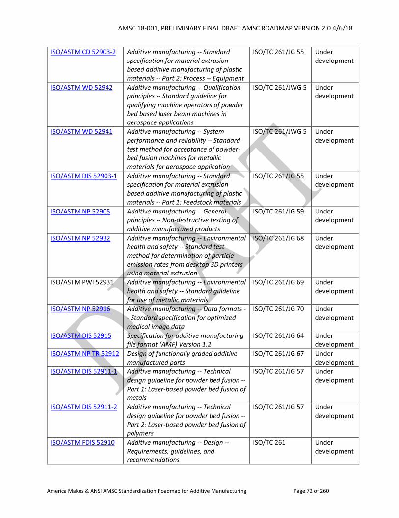
AMSC 18-001, PRELIMINARY FINAL DRAFT AMSC ROADMAP VERSION 2.0 4/6/18
America Makes & ANSI AMSC Standardization Roadmap for Additive Manufacturing Page 72 of 260
ISO/ASTM CD 52903-2 Additive manufacturing -- Standard specification for material extrusion based additive manufacturing of plastic materials -- Part 2: Process -- Equipment
ISO/TC 261/JG 55 Under development
ISO/ASTM WD 52942 Additive manufacturing -- Qualification principles -- Standard guideline for qualifying machine operators of powder bed based laser beam machines in aerospace applications
ISO/TC 261/JWG 5 Under development
ISO/ASTM WD 52941 Additive manufacturing -- System performance and reliability -- Standard test method for acceptance of powder-bed fusion machines for metallic materials for aerospace application
ISO/TC 261/JWG 5 Under development
ISO/ASTM DIS 52903-1 Additive manufacturing -- Standard specification for material extrusion based additive manufacturing of plastic materials -- Part 1: Feedstock materials
ISO/TC 261/JG 55 Under development
ISO/ASTM NP 52905 Additive manufacturing -- General principles -- Non-destructive testing of additive manufactured products
ISO/TC 261/JG 59 Under development
ISO/ASTM NP 52932 Additive manufacturing -- Environmental health and safety -- Standard test method for determination of particle emission rates from desktop 3D printers using material extrusion
ISO/TC 261/JG 68 Under development
ISO/ASTM PWI 52931 Additive manufacturing -- Environmental health and safety -- Standard guideline for use of metallic materials
ISO/TC 261/JG 69 Under development
ISO/ASTM NP 52916 Additive manufacturing -- Data formats -- Standard specification for optimized medical image data
ISO/TC 261/JG 70 Under development
ISO/ASTM DIS 52915 Specification for additive manufacturing file format (AMF) Version 1.2
ISO/TC 261/JG 64 Under development
ISO/ASTM NP TR 52912 Design of functionally graded additive manufactured parts
ISO/TC 261/JG 67 Under development
ISO/ASTM DIS 52911-1 Additive manufacturing -- Technical design guideline for powder bed fusion -- Part 1: Laser-based powder bed fusion of metals
ISO/TC 261/JG 57 Under development
ISO/ASTM DIS 52911-2 Additive manufacturing -- Technical design guideline for powder bed fusion -- Part 2: Laser-based powder bed fusion of polymers
ISO/TC 261/JG 57 Under development
ISO/ASTM FDIS 52910 Additive manufacturing -- Design -- Requirements, guidelines, and recommendations
ISO/TC 261 Under development
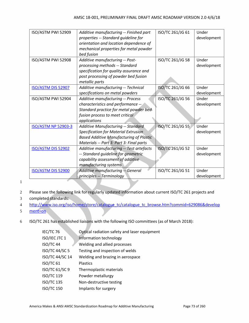
AMSC 18-001, PRELIMINARY FINAL DRAFT AMSC ROADMAP VERSION 2.0 4/6/18
America Makes & ANSI AMSC Standardization Roadmap for Additive Manufacturing Page 73 of 260
ISO/ASTM PWI 52909 Additive manufacturing -- Finished part properties -- Standard guideline for orientation and location dependence of mechanical properties for metal powder bed fusion
ISO/TC 261/JG 61 Under development
ISO/ASTM PWI 52908 Additive manufacturing -- Post-processing methods -- Standard specification for quality assurance and post processing of powder bed fusion metallic parts
ISO/TC 261/JG 58 Under development
ISO/ASTM DIS 52907 Additive manufacturing -- Technical specifications on metal powders
ISO/TC 261/JG 66 Under development
ISO/ASTM PWI 52904 Additive manufacturing -- Process characteristics and performance -- Standard practice for metal powder bed fusion process to meet critical applications
ISO/TC 261/JG 56 Under development
ISO/ASTM NP 52903-3 Additive Manufacturing -- Standard Specification for Material Extrusion Based Additive Manufacturing of Plastic Materials -- Part 3: Part 3: Final parts
ISO/TC 261/JG 55 Under development
ISO/ASTM DIS 52902 Additive manufacturing -- Test artefacts -- Standard guideline for geometric capability assessment of additive manufacturing systems
ISO/TC 261/JG 52 Under development
ISO/ASTM DIS 52900 Additive manufacturing -- General principles -- Terminology
ISO/TC 261/JG 51 Under development
1
Please see the following link for regularly updated information about current ISO/TC 261 projects and 2
completed standards: 3
http://www.iso.org/iso/home/store/catalogue_tc/catalogue_tc_browse.htm?commid=629086&develop4
ment=on 5
ISO/TC 261 has established liaisons with the following ISO committees (as of March 2018): 6
IEC/TC 76 Optical radiation safety and laser equipment
ISO/IEC JTC 1 Information technology
ISO/TC 44 Welding and allied processes
ISO/TC 44/SC 5 Testing and inspection of welds
ISO/TC 44/SC 14 Welding and brazing in aerospace
ISO/TC 61 Plastics
ISO/TC 61/SC 9 Thermoplastic materials
ISO/TC 119 Powder metallurgy
ISO/TC 135 Non-destructive testing
ISO/TC 150 Implants for surgery
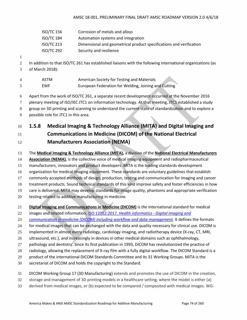
AMSC 18-001, PRELIMINARY FINAL DRAFT AMSC ROADMAP VERSION 2.0 4/6/18
America Makes & ANSI AMSC Standardization Roadmap for Additive Manufacturing Page 74 of 260
ISO/TC 156 Corrosion of metals and alloys
ISO/TC 184 Automation systems and integration
ISO/TC 213 Dimensional and geometrical product specifications and verification
ISO/TC 292 Security and resilience
1
In addition to that ISO/TC 261 has established liaisons with the following international organizations (as 2
of March 2018): 3
ASTM American Society for Testing and Materials 4
EWF European Federation for Welding, Joining and Cutting 5
Apart from the work of ISO/TC 261, a separate recent development occurred at the November 2016 6
plenary meeting of ISO/IEC JTC1 on information technology. At that meeting, JTC1 established a study 7
group on 3D printing and scanning to understand the current state of standardization and to explore a 8
possible role for JTC1 in this area. 9
1.5.8 Medical Imaging & Technology Alliance (MITA) and Digital Imaging and 10
Communications in Medicine (DICOM) of the National Electrical 11
Manufacturers Association (NEMA) 12
The Medical Imaging & Technology Alliance (MITA), a division of the National Electrical Manufacturers 13
Association (NEMA), is the collective voice of medical imaging equipment and radiopharmaceutical 14
manufacturers, innovators and product developers. MITA is the leading standards-development 15
organization for medical imaging equipment. These standards are voluntary guidelines that establish 16
commonly accepted methods of design, production, testing and communication for imaging and cancer 17
treatment products. Sound technical standards of this kind improve safety and foster efficiencies in how 18
care is delivered. MITA may develop standards for image quality, phantoms and appropriate verification 19
testing related to additive manufacturing in medicine. 20
Digital Imaging and Communications in Medicine (DICOM) is the international standard for medical 21
images and related information, ISO 12052:2017, Health informatics - Digital imaging and 22
communication in medicine (DICOM) including workflow and data management. It defines the formats 23
for medical images that can be exchanged with the data and quality necessary for clinical use. DICOM is 24
implemented in almost every radiology, cardiology imaging, and radiotherapy device (X-ray, CT, MRI, 25
ultrasound, etc.), and increasingly in devices in other medical domains such as ophthalmology, 26
pathology and dentistry. Since its first publication in 1993, DICOM has revolutionized the practice of 27
radiology, allowing the replacement of X-ray film with a fully digital workflow. The DICOM Standard is a 28
product of the international DICOM Standards Committee and its 31 Working Groups. MITA is the 29
secretariat of DICOM and holds the copyright to the Standard. 30
DICOM Working Group 17 (3D Manufacturing) extends and promotes the use of DICOM in the creation, 31
storage and management of 3D printing models in a healthcare setting, where the model is either (a) 32
derived from medical images, or (b) expected to be compared / composited with medical images. WG-33
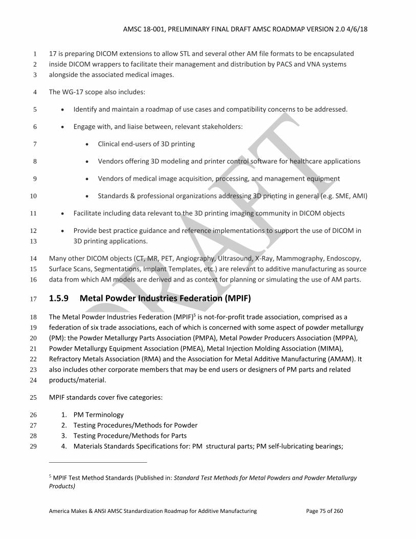
AMSC 18-001, PRELIMINARY FINAL DRAFT AMSC ROADMAP VERSION 2.0 4/6/18
America Makes & ANSI AMSC Standardization Roadmap for Additive Manufacturing Page 75 of 260
17 is preparing DICOM extensions to allow STL and several other AM file formats to be encapsulated 1
inside DICOM wrappers to facilitate their management and distribution by PACS and VNA systems 2
alongside the associated medical images. 3
The WG-17 scope also includes: 4
Identify and maintain a roadmap of use cases and compatibility concerns to be addressed. 5
Engage with, and liaise between, relevant stakeholders: 6
Clinical end-users of 3D printing 7
Vendors offering 3D modeling and printer control software for healthcare applications 8
Vendors of medical image acquisition, processing, and management equipment 9
Standards & professional organizations addressing 3D printing in general (e.g. SME, AMI) 10
Facilitate including data relevant to the 3D printing imaging community in DICOM objects 11
Provide best practice guidance and reference implementations to support the use of DICOM in 12
3D printing applications. 13
Many other DICOM objects (CT, MR, PET, Angiography, Ultrasound, X-Ray, Mammography, Endoscopy, 14
Surface Scans, Segmentations, Implant Templates, etc.) are relevant to additive manufacturing as source 15
data from which AM models are derived and as context for planning or simulating the use of AM parts. 16
1.5.9 Metal Powder Industries Federation (MPIF) 17
The Metal Powder Industries Federation (MPIF)5 is not-for-profit trade association, comprised as a 18
federation of six trade associations, each of which is concerned with some aspect of powder metallurgy 19
(PM): the Powder Metallurgy Parts Association (PMPA), Metal Powder Producers Association (MPPA), 20
Powder Metallurgy Equipment Association (PMEA), Metal Injection Molding Association (MIMA), 21
Refractory Metals Association (RMA) and the Association for Metal Additive Manufacturing (AMAM). It 22
also includes other corporate members that may be end users or designers of PM parts and related 23
products/material. 24
MPIF standards cover five categories: 25
1. PM Terminology 26
2. Testing Procedures/Methods for Powder 27
3. Testing Procedure/Methods for Parts 28
4. Materials Standards Specifications for: PM structural parts; PM self-lubricating bearings; 29
5 MPIF Test Method Standards (Published in: Standard Test Methods for Metal Powders and Powder Metallurgy Products)
AMSC 18-001, PRELIMINARY FINAL DRAFT AMSC ROADMAP VERSION 2.0 4/6/18
America Makes & ANSI AMSC Standardization Roadmap for Additive Manufacturing Page 76 of 260
powder forged (PF) steel; and metal injection molded (MIM) parts 1
5. PM Press Safety Standards (ANSI/MPIF) 2
For the purposes of this document, information is primarily limited to test method standards 3
development. 4
MPIF standards are developed to promote the advancement of the metal powder producing and 5
consuming industries and are based on the commonality of practice within the powder metallurgy and 6
particulate materials industries. MPIF Standards are intended to present and clarify PM technology so as 7
to aid in the conduct of business. 8
Responsibility, Methodology & Approval Practice 9
Certain trade associations within MPIF have established standards committee and subcommittee 10
activities composed of technical people who are responsible for developing standards within their area 11
of expertise. These groups typically meet twice per year for face-to-face meetings (one-two days). 12
MPIF Standards Development Committee activities are populated on a volunteer-basis and financially 13
supported by the various segments of the PM industry. These activities that provide standards 14
development and input (and may include material specifications development/other activity) include: 15
MPIF Standards Committee (conventional PM parts makers and powder producers) 16
PM Self-Lubricating Bearings Subcommittee (bearings parts makers and powder producers) 17
PF Subcommittee (PF parts makers and powder producers) 18
MIMA Standards Committee (MIM parts makers and powder producers) 19
MPPA Standards Committee (conventional PM powder producers) – Maintenance and issuance 20
of standardized methods of test for metal powders 21
AMAM Standards Committee (AM parts makers, powder suppliers, and equipment/service 22
providers) 23
ANSI B11.16-2014 (MPIF #47), PM Press Safety Standards Subcommittee (safety personnel from 24
PM compacting press-builders, end-user PM parts makers, and safety-related equipment 25
suppliers) 26
MPIF standards development is based on the principle that standards follow (common industry 27
practice); they do not lead. 28
MPIF test method standards comprise standard methods and practices/guides. These are developed as 29
follows: 30
A new standard is developed by the appropriate group when an existing need is identified 31
within the industry by its members. 32
Standardized practices/guides are developed to demonstrate the appropriate procedures to 33
follow for achieving a certain task. Guides may reflect various industry practice(s). They may 34
include procedures that demonstrate commonality of practice based on existing industry 35
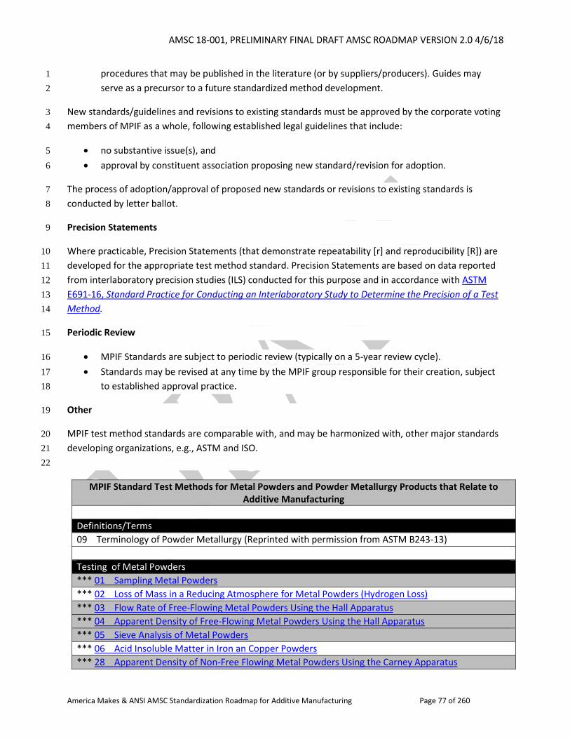
AMSC 18-001, PRELIMINARY FINAL DRAFT AMSC ROADMAP VERSION 2.0 4/6/18
America Makes & ANSI AMSC Standardization Roadmap for Additive Manufacturing Page 77 of 260
procedures that may be published in the literature (or by suppliers/producers). Guides may 1
serve as a precursor to a future standardized method development. 2
New standards/guidelines and revisions to existing standards must be approved by the corporate voting 3
members of MPIF as a whole, following established legal guidelines that include: 4
no substantive issue(s), and 5
approval by constituent association proposing new standard/revision for adoption. 6
The process of adoption/approval of proposed new standards or revisions to existing standards is 7
conducted by letter ballot. 8
Precision Statements 9
Where practicable, Precision Statements (that demonstrate repeatability [r] and reproducibility [R]) are 10
developed for the appropriate test method standard. Precision Statements are based on data reported 11
from interlaboratory precision studies (ILS) conducted for this purpose and in accordance with ASTM 12
E691-16, Standard Practice for Conducting an Interlaboratory Study to Determine the Precision of a Test 13
Method. 14
Periodic Review 15
MPIF Standards are subject to periodic review (typically on a 5-year review cycle). 16
Standards may be revised at any time by the MPIF group responsible for their creation, subject 17
to established approval practice. 18
Other 19
MPIF test method standards are comparable with, and may be harmonized with, other major standards 20
developing organizations, e.g., ASTM and ISO. 21
22
MPIF Standard Test Methods for Metal Powders and Powder Metallurgy Products that Relate to Additive Manufacturing
Definitions/Terms
09 Terminology of Powder Metallurgy (Reprinted with permission from ASTM B243-13)
Testing of Metal Powders
*** 01 Sampling Metal Powders
*** 02 Loss of Mass in a Reducing Atmosphere for Metal Powders (Hydrogen Loss)
*** 03 Flow Rate of Free-Flowing Metal Powders Using the Hall Apparatus
*** 04 Apparent Density of Free-Flowing Metal Powders Using the Hall Apparatus
*** 05 Sieve Analysis of Metal Powders
*** 06 Acid Insoluble Matter in Iron an Copper Powders
*** 28 Apparent Density of Non-Free Flowing Metal Powders Using the Carney Apparatus
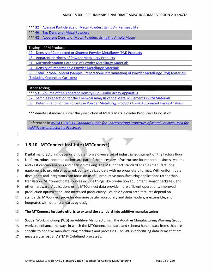
AMSC 18-001, PRELIMINARY FINAL DRAFT AMSC ROADMAP VERSION 2.0 4/6/18
America Makes & ANSI AMSC Standardization Roadmap for Additive Manufacturing Page 78 of 260
*** 32 Average Particle Size of Metal Powders Using Air Permeability
*** 46 Tap Density of Metal Powders
*** 48 Apparent Density of Metal Powders Using the Arnold Meter
Testing of PM Products
42 Density of Compacted or Sintered Powder Metallurgy (PM) Products
43 Apparent Hardness of Powder Metallurgy Products
51 Microindentation Hardness of Powder Metallurgy Materials
54 Density of Impermeable Powder Metallurgy Materials
66 Total Carbon Content (Sample Preparation/Determination) of Powder Metallurgy (PM) Materials (Excluding Cemented Carbides)
Other Testing
*** 53 Volume of the Apparent Density Cup—Hall/Carney Apparatus
67 Sample Preparation for the Chemical Analysis of the Metallic Elements in PM Materials
69 Determination of the Porosity in Powder Metallurgy Products Using Automated Image Analysis
*** denotes standards under the jurisdiction of MPIF’s Metal Powder Producers Association
Referenced in ASTM F3049-14, Standard Guide for Characterizing Properties of Metal Powders Used for Additive Manufacturing Processes
1
1.5.10 MTConnect Institute (MTConnect) 2
Digital manufacturing depends on data from a diverse set of industrial equipment on the factory floor. 3
Uniform, robust communications are part of the necessary infrastructure for modern business systems 4
and 21st century analysis and decision-making. The MTConnect standard enables manufacturing 5
equipment to provide structured, contextualized data with no proprietary format. With uniform data, 6
developers and integrators can focus on useful, productive manufacturing applications rather than 7
translation. MTConnect data sources include things like production equipment, sensor packages, and 8
other hardware. Applications using MTConnect data provide more efficient operations, improved 9
production optimization, and increased productivity. Scalable system architectures depend on 10
standards. MTConnect provides domain-specific vocabulary and data models, is extensible, and 11
integrates with other standards by design. 12
The MTConnect Institute efforts to extend the standard into additive manufacturing 13
Scope: Working Group (WG) on Additive Manufacturing: The Additive Manufacturing Working Group 14
works to enhance the ways in which the MTConnect standard and schema handle data items that are 15
specific to additive manufacturing machines and processes. The WG is prioritizing data items that are 16
necessary across all ASTM F42-defined processes. 17
AMSC 18-001, PRELIMINARY FINAL DRAFT AMSC ROADMAP VERSION 2.0 4/6/18
America Makes & ANSI AMSC Standardization Roadmap for Additive Manufacturing Page 79 of 260
Purpose: To extend the MTConnect standard’s data dictionary in order to support information transfer 1
from a data source (i.e., additive manufacturing equipment) to an MTConnect agent and subsequently 2
transfer those electronic documents from an MTConnect agent to a client software application. Given 3
the increased demand for additive manufacturing equipment definitions and semantic information 4
models, the WG was formed by industrial original equipment manufacturers (OEMs) and is being driven 5
by the industrial community with a consensus-based approach. 6
1.5.11 SAE International (SAE) 7
SAE International is a global association of over 127,000 engineers and technical experts serving as the 8
ultimate knowledge source for the mobility engineering profession. As the world’s largest aerospace 9
consensus standards developing organization, SAE maintains over 8,500 active aerospace technical 10
standards utilized by the military and civilian aviation industry, government, and research stakeholders. 11
SAE International Additive Manufacturing Aerospace Standardization Activity 12
Established in July 2015, SAE AMS-AM, Additive Manufacturing, is a technical committee in SAE 13
International’s Aerospace Materials Systems Group responsible for developing and maintaining 14
aerospace material and process specifications and other SAE technical reports for additive 15
manufacturing, including precursor materials, additive processes, system requirements and post-build 16
materials, pre-processing and post-processing, nondestructive testing, and quality assurance. 17
The objectives of the AMS-AM committee are to: 18
Develop Aerospace Material Specifications (AMS) for the procurement of additive precursor and 19
manufactured materials including metals, plastics, ceramics, composites, and hybrids made by 20
additive technologies. When applicable, the material specification is tied to the appropriate 21
shared material property database. 22
Publish recommended practices, specifications, and standards for processing and fabrication of 23
aerospace end products from AM materials. 24
Further the adoption of industry sponsored material specifications through coordination with the 25
Metallic Materials Properties Development and Standardization (MMPDS) Handbook, Composite 26
Materials Handbook (CMH-17), ASTM Committee F42 on Additive Manufacturing, AWS D20, 27
ASTM Committee E07.10 on Specialized NDT Methods, Nadcap Welding Task Group, other AMS 28
committees and associated organizations. 29
Coordinate requirements for publishing data in shared material property databases with the 30
MMPDS Emerging Technology Working Group for new metallic materials and CMH-17 for new 31
polymer and composite materials. 32
Establish a system to ensure material specifications are controlled and traceable to statistically 33
substantiated data analyzed by documented procedures. 34
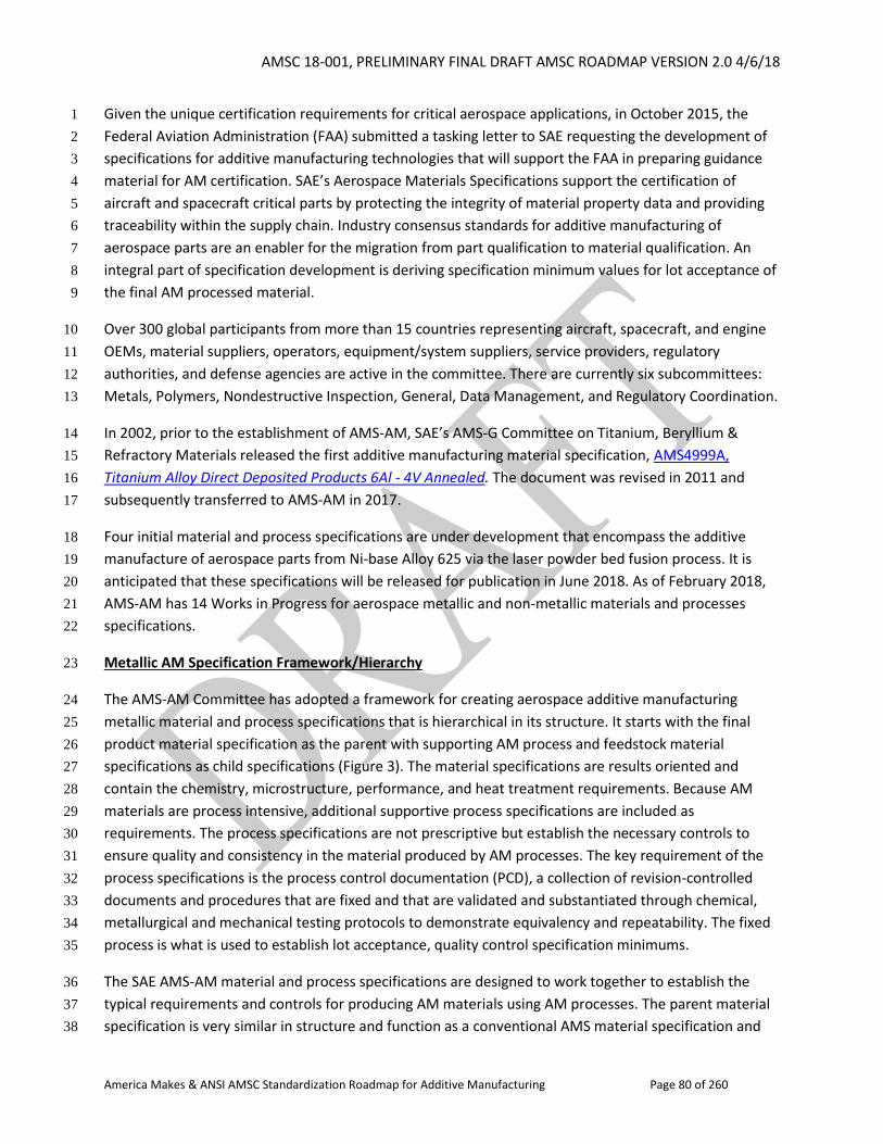
AMSC 18-001, PRELIMINARY FINAL DRAFT AMSC ROADMAP VERSION 2.0 4/6/18
America Makes & ANSI AMSC Standardization Roadmap for Additive Manufacturing Page 80 of 260
Given the unique certification requirements for critical aerospace applications, in October 2015, the 1
Federal Aviation Administration (FAA) submitted a tasking letter to SAE requesting the development of 2
specifications for additive manufacturing technologies that will support the FAA in preparing guidance 3
material for AM certification. SAE’s Aerospace Materials Specifications support the certification of 4
aircraft and spacecraft critical parts by protecting the integrity of material property data and providing 5
traceability within the supply chain. Industry consensus standards for additive manufacturing of 6
aerospace parts are an enabler for the migration from part qualification to material qualification. An 7
integral part of specification development is deriving specification minimum values for lot acceptance of 8
the final AM processed material. 9
Over 300 global participants from more than 15 countries representing aircraft, spacecraft, and engine 10
OEMs, material suppliers, operators, equipment/system suppliers, service providers, regulatory 11
authorities, and defense agencies are active in the committee. There are currently six subcommittees: 12
Metals, Polymers, Nondestructive Inspection, General, Data Management, and Regulatory Coordination. 13
In 2002, prior to the establishment of AMS-AM, SAE’s AMS-G Committee on Titanium, Beryllium & 14
Refractory Materials released the first additive manufacturing material specification, AMS4999A, 15
Titanium Alloy Direct Deposited Products 6Al - 4V Annealed. The document was revised in 2011 and 16
subsequently transferred to AMS-AM in 2017. 17
Four initial material and process specifications are under development that encompass the additive 18
manufacture of aerospace parts from Ni-base Alloy 625 via the laser powder bed fusion process. It is 19
anticipated that these specifications will be released for publication in June 2018. As of February 2018, 20
AMS-AM has 14 Works in Progress for aerospace metallic and non-metallic materials and processes 21
specifications. 22
Metallic AM Specification Framework/Hierarchy 23
The AMS-AM Committee has adopted a framework for creating aerospace additive manufacturing 24
metallic material and process specifications that is hierarchical in its structure. It starts with the final 25
product material specification as the parent with supporting AM process and feedstock material 26
specifications as child specifications (Figure 3). The material specifications are results oriented and 27
contain the chemistry, microstructure, performance, and heat treatment requirements. Because AM 28
materials are process intensive, additional supportive process specifications are included as 29
requirements. The process specifications are not prescriptive but establish the necessary controls to 30
ensure quality and consistency in the material produced by AM processes. The key requirement of the 31
process specifications is the process control documentation (PCD), a collection of revision-controlled 32
documents and procedures that are fixed and that are validated and substantiated through chemical, 33
metallurgical and mechanical testing protocols to demonstrate equivalency and repeatability. The fixed 34
process is what is used to establish lot acceptance, quality control specification minimums. 35
The SAE AMS-AM material and process specifications are designed to work together to establish the 36
typical requirements and controls for producing AM materials using AM processes. The parent material 37
specification is very similar in structure and function as a conventional AMS material specification and 38
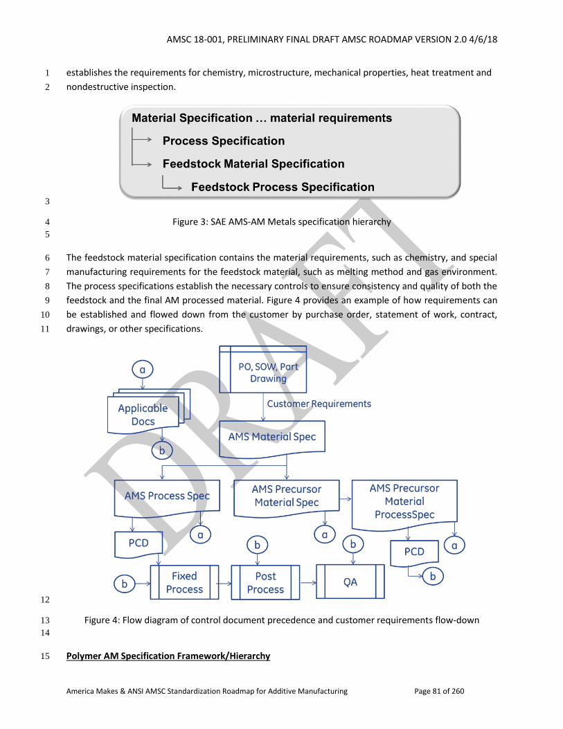
AMSC 18-001, PRELIMINARY FINAL DRAFT AMSC ROADMAP VERSION 2.0 4/6/18
America Makes & ANSI AMSC Standardization Roadmap for Additive Manufacturing Page 81 of 260
establishes the requirements for chemistry, microstructure, mechanical properties, heat treatment and 1
nondestructive inspection. 2
3
Figure 3: SAE AMS-AM Metals specification hierarchy 4
5
The feedstock material specification contains the material requirements, such as chemistry, and special 6
manufacturing requirements for the feedstock material, such as melting method and gas environment. 7
The process specifications establish the necessary controls to ensure consistency and quality of both the 8
feedstock and the final AM processed material. Figure 4 provides an example of how requirements can 9
be established and flowed down from the customer by purchase order, statement of work, contract, 10
drawings, or other specifications. 11
12
Figure 4: Flow diagram of control document precedence and customer requirements flow-down 13
14
Polymer AM Specification Framework/Hierarchy 15

AMSC 18-001, PRELIMINARY FINAL DRAFT AMSC ROADMAP VERSION 2.0 4/6/18
America Makes & ANSI AMSC Standardization Roadmap for Additive Manufacturing Page 82 of 260
SAE International’s AMS AM-P is a subcommittee of AMS-AM initiated in January 2017 at the request of 1
the International Air Transport Association (IATA) to assist airlines utilizing additive manufacturing to 2
produce cabin parts. The subcommittee’s documents will also support the broader aerospace industry’s 3
interest in qualifying polymer AM parts. The initial three specifications under development provide 4
technical requirements and quality assurance provisions for the Fused Deposition Modeling process and 5
material feedstock characterization needed to produce high quality parts for aerospace applications 6
utilizing Stratasys ULTEM™ 9085 and ULTEM™ 1010. 7
AMS AM-P is developing a unique specification framework applicable for both filled and unfilled 8
polymers. Working closely with the National Institute for Aviation Research (NIAR) FAA-funded project 9
to develop a framework for qualification of polymer-based AM materials, AMS AM-P industry specs will 10
assist with the transition of the test data into shared databases such as CMH-17. The framework under 11
development includes a base specification, which will include estimated values for selected mechanical 12
properties, and in some cases, a detailed specification (or slash sheet), which will contain the statistically 13
derived specification minimum values. 14
Aerospace Materials 15
As with any other conventional material, by establishing controls on the manufacturing process, 16
consistent and predictable results can be attained in the material chemistry and microstructure, thereby 17
resulting in consistent and predictable properties and performance. The current SAE AMS-AM additive 18
manufacturing specification strategy establishes controls on the input feedstock and AM process while 19
relying on existing standards and specifications for commodity processes such as heat treatment and 20
nondestructive inspection (NDI) as shown in Figure 5: 21
22
Figure 5 23
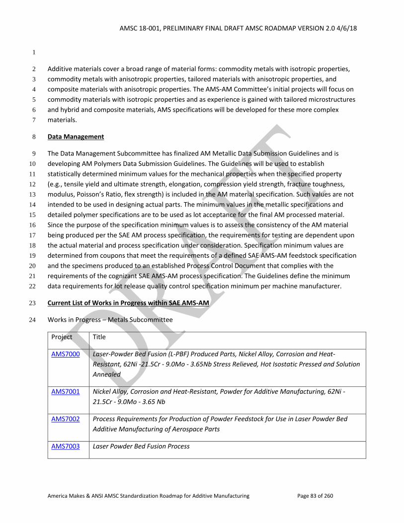
AMSC 18-001, PRELIMINARY FINAL DRAFT AMSC ROADMAP VERSION 2.0 4/6/18
America Makes & ANSI AMSC Standardization Roadmap for Additive Manufacturing Page 83 of 260
1
Additive materials cover a broad range of material forms: commodity metals with isotropic properties, 2
commodity metals with anisotropic properties, tailored materials with anisotropic properties, and 3
composite materials with anisotropic properties. The AMS-AM Committee’s initial projects will focus on 4
commodity materials with isotropic properties and as experience is gained with tailored microstructures 5
and hybrid and composite materials, AMS specifications will be developed for these more complex 6
materials. 7
Data Management 8
The Data Management Subcommittee has finalized AM Metallic Data Submission Guidelines and is 9
developing AM Polymers Data Submission Guidelines. The Guidelines will be used to establish 10
statistically determined minimum values for the mechanical properties when the specified property 11
(e.g., tensile yield and ultimate strength, elongation, compression yield strength, fracture toughness, 12
modulus, Poisson’s Ratio, flex strength) is included in the AM material specification. Such values are not 13
intended to be used in designing actual parts. The minimum values in the metallic specifications and 14
detailed polymer specifications are to be used as lot acceptance for the final AM processed material. 15
Since the purpose of the specification minimum values is to assess the consistency of the AM material 16
being produced per the SAE AM process specification, the requirements for testing are dependent upon 17
the actual material and process specification under consideration. Specification minimum values are 18
determined from coupons that meet the requirements of a defined SAE AMS-AM feedstock specification 19
and the specimens produced to an established Process Control Document that complies with the 20
requirements of the cognizant SAE AMS-AM process specification. The Guidelines define the minimum 21
data requirements for lot release quality control specification minimum per machine manufacturer. 22
Current List of Works in Progress within SAE AMS-AM 23
Works in Progress – Metals Subcommittee 24
Project Title
AMS7000 Laser-Powder Bed Fusion (L-PBF) Produced Parts, Nickel Alloy, Corrosion and Heat-
Resistant, 62Ni -21.5Cr - 9.0Mo - 3.65Nb Stress Relieved, Hot Isostatic Pressed and Solution
Annealed
AMS7001 Nickel Alloy, Corrosion and Heat-Resistant, Powder for Additive Manufacturing, 62Ni -
21.5Cr - 9.0Mo - 3.65 Nb
AMS7002 Process Requirements for Production of Powder Feedstock for Use in Laser Powder Bed
Additive Manufacturing of Aerospace Parts
AMS7003 Laser Powder Bed Fusion Process
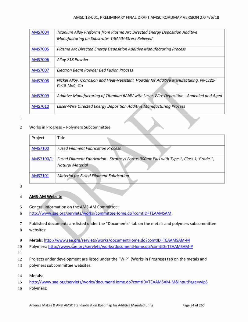
AMSC 18-001, PRELIMINARY FINAL DRAFT AMSC ROADMAP VERSION 2.0 4/6/18
America Makes & ANSI AMSC Standardization Roadmap for Additive Manufacturing Page 84 of 260
AMS7004 Titanium Alloy Preforms from Plasma Arc Directed Energy Deposition Additive
Manufacturing on Substrate- Ti6Al4V-Stress Relieved
AMS7005 Plasma Arc Directed Energy Deposition Additive Manufacturing Process
AMS7006 Alloy 718 Powder
AMS7007 Electron Beam Powder Bed Fusion Process
AMS7008 Nickel Alloy, Corrosion and Heat-Resistant, Powder for Additive Manufacturing, Ni-Cr22-
Fe18-Mo9–Co
AMS7009 Additive Manufacturing of Titanium 6Al4V with Laser-Wire Deposition - Annealed and Aged
AMS7010 Laser-Wire Directed Energy Deposition Additive Manufacturing Process
1
Works in Progress – Polymers Subcommittee 2
Project Title
AMS7100 Fused Filament Fabrication Process
AMS7100/1 Fused Filament Fabrication - Stratasys Fortus 900mc Plus with Type 1, Class 1, Grade 1,
Natural Material
AMS7101 Material for Fused Filament Fabrication
3
AMS-AM Website 4
General Information on the AMS-AM Committee: 5
http://www.sae.org/servlets/works/committeeHome.do?comtID=TEAAMSAM. 6
Published documents are listed under the “Documents” tab on the metals and polymers subcommittee 7
websites: 8
Metals: http://www.sae.org/servlets/works/documentHome.do?comtID=TEAAMSAM-M 9
Polymers: http://www.sae.org/servlets/works/documentHome.do?comtID=TEAAMSAM-P 10
11
Projects under development are listed under the “WIP” (Works in Progress) tab on the metals and 12
polymers subcommittee websites: 13
Metals: 14
http://www.sae.org/servlets/works/documentHome.do?comtID=TEAAMSAM-M&inputPage=wIpS 15
Polymers: 16
AMSC 18-001, PRELIMINARY FINAL DRAFT AMSC ROADMAP VERSION 2.0 4/6/18
America Makes & ANSI AMSC Standardization Roadmap for Additive Manufacturing Page 85 of 260
http://www.sae.org/servlets/works/documentHome.do?comtID=TEAAMSAM-P&inputPage=wIpS 1
2
Additional SAE International Technical Committees with Interests in Additive Manufacturing 3
In addition to SAE’s AMS-AM, Additive Manufacturing Committee which specifically focuses on additive 4
manufacturing, other SAE Technical Committees identified by the AMSC as having subject matter 5
expertise relevant to AM include: 6
AMS Committee B, Finishes, Processes & Fluids prepares, coordinates, and revises documents related 7
to processing technology, such as plating, brazing, coatings and compounds, through the participation of 8
process suppliers, users, and interested government agencies. Committee activities shall provide a 9
forum for the cooperative interchange of ideas and experience of the participants, resulting in the 10
publication of specifications that embody sound, established aerospace industry practices and 11
requirements to serve the suppliers and customers of aerospace processes. Areas of applicability to AM 12
include heat treatment, hot isostatic pressing, and electron beam welding. For additional information, 13
please visit: http://www.sae.org/servlets/works/committeeHome.do?comtID=TEAAMSB. 14
15
AMS Committee K, Nondestructive Methods & Processes prepares, coordinates, and revises 16
documents related to nondestructive testing technology, such as fluorescent penetrant, magnetic 17
particle, X-ray, ultrasonic, and eddy current, through the participation of manufacturer's suppliers, 18
users, airlines, and interested government agencies. For additional information, please visit: 19
http://www.sae.org/servlets/works/committeeHome.do?comtID=TEAAMSK. 20
21
SMC G-33, Configuration Management Committee prepares positions on government policies, 22
practices, specifications, and standards dealing with technical data, drawing practices, and configuration 23
management practices. It promotes understanding of configuration and data management principles 24
and develops standards. For additional information, please visit: 25
http://www.sae.org/servlets/works/committeeHome.do?comtID=SMCG33. 26
27
SMC G-41, Reliability Committee focuses on standards and handbooks that take a systems engineering 28
approach to reliability that align best practices of reliability management, design and testing with 29
reliability methods that provide the most value and the least risk in terms of achieving reliable products. 30
The demand for highly-reliable systems/products prompted the development of a ANSI/GEIA-STD-0009 31
(Reliability Program Standard for Systems Design, Development, and Manufacturing) and the 32
corresponding handbook, TA-HB-009 (Reliability Program Handbook) that specifies a scientific approach 33
to reliability design, assessment, and verification, coupled with integrated management and systems 34
engineering. For additional information, please visit: 35
http://www.sae.org/servlets/works/committeeHome.do?comtID=TEASSTCG41. 36
37
SMC LCLS, Life Cycle Logistics Supportability Committee focuses on standards and handbooks that 38
facilitate the acquisition logistics process. By developing and maintaining supportability standards and 39
handbooks, coalescing industry positions and preparing and coordinating positions on government 40

AMSC 18-001, PRELIMINARY FINAL DRAFT AMSC ROADMAP VERSION 2.0 4/6/18
America Makes & ANSI AMSC Standardization Roadmap for Additive Manufacturing Page 86 of 260
policies and practices the committee is the industry innovation point for Logistics Product Data. Areas of 1
applicability to AM include Level of Repair Analysis (LORA). For additional information, please visit: 2
http://www.sae.org/servlets/works/committeeHome.do?comtID=SMCLCLS. 3
4
G-11M, Maintainability, Supportability & Logistics Committee addresses maintainability, supportability, 5
and logistics tools, processes, procedures, and best practices. It provides an industry/government forum 6
to review technology and investigates the interfaces with engineering design and development, support 7
costs, maintainability, reliability, reparability, tooling, and diagnostics. Areas of applicability to AM 8
include Reliability-Centered Maintenance (RCM) and Condition Based Maintenance (CBM). For 9
additional information, please visit: 10
http://www.sae.org/servlets/works/committeeHome.do?comtID=TEAG11M. 11
12
13
AMSC 18-001, PRELIMINARY FINAL DRAFT AMSC ROADMAP VERSION 2.0 4/6/18
America Makes & ANSI AMSC Standardization Roadmap for Additive Manufacturing Page 87 of 260
2. Gap Analysis of Standards and Specifications 1
This roadmap chapter sets forth a description of key issues; relevant published standards and 2
specifications, as well as those in development; recommendations on the need for additional R&D 3
and/or standards and specs, as well as priorities for their development; and the organization(s) that 4
potentially could perform the work. It is divided into several sections corresponding to the AMSC 5
working groups. These are: Design, Process and Materials, Qualification and Certification, 6
Nondestructive Evaluation, and Maintenance. The Process and Materials section is further divided into 7
four sections corresponding to the AMSC subgroups on Precursor Materials, Process Control, Post-8
processing, and Finished Materials Properties. 9
2.1 Design 10
11
2.1.1 Introduction 12
13
Additive manufacturing offers unique design opportunities not afforded by traditional manufacturing 14
processes. These opportunities include unique lattice structures and material gradients as well as other 15
novel designs such as the creation of inseparable assemblies or embedded electronics. 16
17
This section will assess the currently available and developing industry standards and specifications 18
relevant to the AM design process. Specifically, design guides, design tools, design documentation, and 19
design verification and validation (V&V) will be discussed as well design standards relevant to specific 20
applications such as medical and electronics. Gaps in applying these standards and methods to AM shall 21
be identified, and recommendations will be made to address them. 22
23
AM designs must ultimately be documented in a product definition data set that includes all of the 24
information necessary to build a part. However, AM presents challenges to designers seeking to apply 25
traditional design methods for part manufacturing. To aid them, the existing design systems, processes, 26
and methodologies must be evaluated for their applicability to AM, and in special cases new ones may 27
be required. 28
29
2.1.2 Design Guides 30
31
Design guidelines for AM serve to support users in both design and manufacturing decisions. Guidelines 32
are used to highlight AM process capabilities and inform users on process limitations and requirements. 33
Different AM processes have different design requirements, manufacturing requirements, and 34
manufacturing capabilities. Design guides potentially could also be used to help designers consider other 35
factors such as reliability, cost assessment, logistics, and risk assessment. 36
As AM has matured as a technology, design guidelines have become more prevalent and more 37
advanced. Guidelines are developed as process-independent, process-specific, manufacturer-specific, 38
AMSC 18-001, PRELIMINARY FINAL DRAFT AMSC ROADMAP VERSION 2.0 4/6/18
America Makes & ANSI AMSC Standardization Roadmap for Additive Manufacturing Page 88 of 260
and application-specific. Design guides do not necessarily need to be developed by SDOs. They are also 1
available from equipment manufacturers and service providers, though these are not generally 2
identified in this document. 3
General Guides for AM 4
From the standards perspective, ASTM F42 and ISO TC261 have taken the lead in the development of 5
design guidelines, though none currently exist as released standards. 6
Gap D1: Decision Support: Additive vs. Subtractive. Currently there is no standard that helps users 7
understand the advantages/disadvantages of AM processes versus traditional manufacturing processes 8
while also providing decision criteria so informed design/manufacturing decisions can be made. 9
R&D Needed: TBD 10
Recommendation: Develop a guideline that helps understand trade-offs between AM processes and 11
traditional processes (e.g., sacrifice design freedom for greater certainty of established processes in 12
terms of material properties, reliability, etc.). 13
Priority: Medium 14
Status of Progress: Green (SME) in terms of a tool providing general guidance, though not a standard 15
Update: No standards are planned or in development. Commercial tools are available. SME and the 16
ITEAM (Independent Technical Evaluation of Additive Manufacturing) Consortium are developing a new 17
prototype AM Rapid Virtual Evaluation Platform, SAM-CT, which will be publicly available in April 2018 18
and will aid in 3DP decision making. 19
Organization: ISO/ASTM, AWS, SAE, SME 20
21
Gap D2: Decision Support: Additive Processes. The version 1.0 gap stated that there is no standard that 22
normalizes the characteristics of the general AM process and ranks the pros/cons or 23
strengths/weaknesses of each process, allowing users to make informed decisions about which AM 24
process best suits their need. In 2017, ISO/ASTM published ISO/ASTM 52910-17, Standard Guidelines for 25
Design for Additive Manufacturing (work item previously known as ASTM WK38342). The standard 26
briefly addresses AM process selection, providing an example of a high-level diagram and with section 27
6.8.2, specific process considerations. However, additional standards may be needed to address trade-28
off criteria between processes. 29
R&D Needed: Yes. R&D is needed to identify trade-off criteria. 30
Recommendation: Continue work to complement what has been published in ISO/ASTM 52910-2017. 31
Focus on identification of trade-off criteria between processes. There is still a need to develop a 32
standard for reporting process inputs and capabilities. 33
AMSC 18-001, PRELIMINARY FINAL DRAFT AMSC ROADMAP VERSION 2.0 4/6/18
America Makes & ANSI AMSC Standardization Roadmap for Additive Manufacturing Page 89 of 260
Priority: Medium 1
Status of Progress: Green. Gap partially closed in relation to standards with the publication of ISO/ASTM 2
52910-17. 3
Update: The gap statement and recommendation have been updated in light of the publication of 4
ISO/ASTM 52910-17. 5
Organization: National labs and government agencies for the R&D. ISO/TC 261 & ASTM F42 for the 6
standards work. 7
Process-Specific Guides for AM 8
ASTM and ISO plan to continue to jointly develop guidelines following the standards development 9
framework they have agreed to (Figure 2). Accordingly, process-specific design guidelines are beginning 10
to be developed. ISO/TC 261 and ASTM F42, via JG 57, are jointly developing technical design guidelines 11
for laser-based powder bed fusion (PBF-L) for both metals (ISO/ASTM DIS 52911-1, previously ASTM 12
WK59131) and polymers (ISO/ASTM DIS 52911-2, previously ASTM WK59167). These are similar in 13
concept to an existing German standard VDI 3405. Work is ongoing for electron beam. There is another 14
standard being contemplated on material extrusion. In addition, AWS is developing D20.1 which will 15
address directed energy deposition (DED) and PBF processes. 16
Gap D3: Process-Specific Design Guidelines. There are no available AM process-specific design 17
guidelines. The design guidelines currently being developed by JG 57 are process-specific design 18
guidelines under joint development by ASTM F42 and ISO/TC 261. ASTM and ISO identify 7 types of AM 19
processes, meaning that 6 AM processes do not have guidelines under development. 20
R&D Needed: No, for the guidelines on PBF. Not yet determined for the other six processes. 21
Recommendation: Complete work on the ISO/ASTM JG 57 design guidelines for PBF. Develop guidelines 22
for the six other AM processes defined in ISO/ASTM 52900:2015, Additive manufacturing -- General 23
principles – Terminology. 24
Priority: Medium 25
Status of Progress: Green (ISO/ASTM) for PBF. Green (AWS) for PBF and DED. Not Started for the other 26
processes defined in ISO/ASTM 52900. 27
Update: As noted in the text, ISO/ASTM JG 57 design guidelines are being developed for PBF-L for 28
metals and polymers. Work on electron beam continues. AWS D20.1 will address PBF and DED, as noted 29
in the text. 30
Organization: ASTM F42/ISO TC 261 JG 57, AWS 31
Application-Specific Design Guides for AM 32
AMSC 18-001, PRELIMINARY FINAL DRAFT AMSC ROADMAP VERSION 2.0 4/6/18
America Makes & ANSI AMSC Standardization Roadmap for Additive Manufacturing Page 90 of 260
Following the ASTM/ISO framework (Figure 2), the next generation of design guidelines are expected to 1
be application specific. Candidates for early application-specific guidelines include Design for Aerospace, 2
Design for Medical, Design for Automotive, etc. The current landscape suggests that such standards may 3
be developed by ASTM F42 and ISO/TC 261. ISO/TC 44/SC 14, Welding and brazing in aerospace, also 4
has formed a WG 1, Additive manufacturing in Aerospace. While this group is application-specific, the 5
design implications are unclear. Design guidelines are often manufacturer-specific. 6
Gap D4: Application-Specific Design Guidelines. As industry fields mature in particular AM applications, 7
best practices should be recorded. 8
R&D Needed: TBD 9
Recommendation: It is recommended that any application-specific design guides extend available 10
process-independent and process-specific design guides. However, application-specific design guidelines 11
may also need to be developed by their respective communities, and in such cases these guidelines may 12
fall under respective societies or SDOs. For instance, a design guideline for printed electronics may be 13
best suited for an organization such as IEEE or IPC. 14
Priority: High 15
Status of Progress: Green 16
Update: ASME is working on design guides for pressure retaining equipment (e.g., pressure vessels). 17
Other SDOs need to consult with their committees. Some of the SAE process specifications may address 18
this. 19
Organization: ASME, SAE, ASTM F42/ISO TC 261, and potentially other SDOs et al. (e.g., manufacturers, 20
industry consortia) 21
Machine Customizable/Adaptive Guides for AM 22
Many manufacturers, including those of hobbyist machines as well as production machines, have begun 23
to provide guidelines to help in decision-making and process-planning for their specific machines (e.g., 24
EOS, Makerbot documentation). Service providers have begun to provide design guidelines to help 25
customers better understand manufacturing constraints and better prepare designs before sending 26
them to a service provider to be manufactured (e.g., Xometry and documentation). The implications are 27
that guidelines and rules may become machine and implementation specific. 28
Gap D5: Support for Customizable Guidelines. Producing the same part on different machines from 29
different manufacturers and often the same manufacturer will return different results. While process 30
and application guidelines will provide meaningful insight, additional tailoring may be needed for 31
specific instantiations. Guidelines on how to extend process and application guidelines would allow 32
users to further adapt and specify to fit individual needs. 33
AMSC 18-001, PRELIMINARY FINAL DRAFT AMSC ROADMAP VERSION 2.0 4/6/18
America Makes & ANSI AMSC Standardization Roadmap for Additive Manufacturing Page 91 of 260
R&D Needed: Yes. Customizable guidelines require understanding process/machine/design 1
characteristics and subsequent tradeoffs. 2
Recommendation: As machines are benchmarked and calibrated, designers should have mechanisms 3
available to them that will provide operational constraints on their available AM processes. Designers 4
should understand what geometric and process liberties might be taken for their particular 5
implementation. 6
Priority: Medium 7
Status of Progress: Green 8
Update: ASTM WK54856, New Guide for Principles of Design Rules in Additive Manufacturing, has an 9
expected release of late 2018/early 2019. 10
Organization: ISO/ASTM 11
12
Gap D6: Software-encodable/Machine-readable Guidelines. In addition to design guidelines, 13
complementary efforts have been initiated under ASTM Committee F42 on Additive Manufacturing 14
Technologies (F42) to support the development of standardized design rules. Guidelines that are in 15
development rely heavily on graphics/drawings and narrative through natural language, leaving often 16
subjective interpretations. The ASTM WK54856, New Guide for Principles of Design Rules in Additive 17
Manufacturing work item under development in ASTM F42 aims to provide explicit constructs from 18
which explicit design rules can be developed and customized. These constructs will also provide a 19
machine-interpretable language that will support software implementation. The standard has an 20
expected release of late 2018/early 2019. 21
R&D Needed: Yes. The identification of fundamental constructs should mirror key characteristics and 22
decision criteria for designs, materials, and processes. 23
Recommendation: Standardize a language that can be interpreted by both humans and machines so 24
that design for AM can be simplified and communicated across platforms, and constraints can be 25
encoded into design software. 26
Priority: Medium 27
Status of Progress: Green 28
Update: This gap is being addressed by ASTM WK54856. 29
Organization: ASTM, ISO, ASME, IEEE-ISTO PWG 30
Design Guide for Post-processing 31
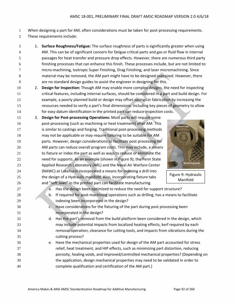
AMSC 18-001, PRELIMINARY FINAL DRAFT AMSC ROADMAP VERSION 2.0 4/6/18
America Makes & ANSI AMSC Standardization Roadmap for Additive Manufacturing Page 92 of 260
When designing a part for AM, often considerations must be taken for post-processing requirements. 1
These requirements include: 2
1. Surface Roughness/Fatigue: The surface roughness of parts is significantly greater when using 3
AM. This can be of significant concern for fatigue critical parts and gas or fluid flow in internal 4
passages for heat transfer and pressure drop effects. However, there are numerous third party 5
finishing processes that can enhance this finish. These processes include, but are not limited to: 6
micro-machining, Isotropic Super Finishing, Drag Finishing, and laser micromachining. Since 7
material may be removed, the AM part might have to be designed oversized. However, there 8
are no standard design guides to assist the engineer in designing for this. 9
2. Design for Inspection: Though AM may enable more complex designs, the need for inspecting 10
critical features, including internal surfaces, should be considered in a part and build design. For 11
example, a poorly planned build or design may offset savings in fabrication by increasing the 12
resources needed to verify a part’s final dimensions. Including key pieces of geometry to allow 13
for easy datum identification in the printed part can reduce inspection costs. 14
3. Design for Post-processing Operations: Most parts will require some 15
post-processing (such as machining or heat treatment) after AM. This 16
is similar to castings and forging. Traditional post-processing methods 17
may not be applicable or may require tailoring to be suitable for AM 18
parts. However, design considerations to facilitate post processing for 19
AM parts can reduce overall program costs. This may include, a means 20
to fixture or index the part as well as ways to reduce or eliminate the 21
need for supports. As an example (shown in Figure 9), the Penn State 22
Applied Research Laboratory (ARL) and the Naval Air Warfare Center 23
(NAWC) at Lakehurst incorporated a means for indexing a drill into 24
the design of a Hydraulic manifold. Also, incorporating fixture tabs 25
and "soft Jaws" in the printed part can facilitate manufacturing. 26
a. Has the design been optimized to reduce the need for support structure? 27
b. If required for post-machining operations such as drilling, has a means to facilitate 28
indexing been incorporated in the design? 29
c. Have considerations for the fixturing of the part during post processing been 30
incorporated in the design? 31
d. Has the part’s removal from the build platform been considered in the design, which 32
may include potential impacts from localized heating effects, kerf required by each 33
removal operation, clearance for cutting tools, and impacts from vibrations during the 34
cutting process? 35
e. Have the mechanical properties used for design of the AM part accounted for stress 36
relief, heat treatment, and HIP effects, such as minimizing part distortion, reducing 37
porosity, healing voids, and improved/controlled mechanical properties? (Depending on 38
the application, design mechanical properties may need to be validated in order to 39
complete qualification and certification of the AM part.) 40
Figure 9: Hydraulic Manifold
AMSC 18-001, PRELIMINARY FINAL DRAFT AMSC ROADMAP VERSION 2.0 4/6/18
America Makes & ANSI AMSC Standardization Roadmap for Additive Manufacturing Page 93 of 260
4. Design for Heat Treatment: Designers need to understand how post-processing heat treatments 1
and stress relief can impact the material properties and the intent of the design. For example, 2
thermal post-processing may be used to remove residual stresses that could have resulted in 3
part distortion; heat treatments can be used to tailor and improve mechanical properties; and 4
HIP may reduce defects and porosity. Heat treatment methods that are standardized and 5
validated (through experimentation) need to be developed for AM and may be adapted from 6
“traditional” methods. 7
5. Design Parts for Safe AM Processing and Post-Processing: When designing parts and build plans 8
for fabrication by AM methods, safety must be considered for personnel operating the machines 9
and conducting post-processing tasks. 10
a. Parts should avoid trapped volumes which could trap unused liquid or powder build 11
materials (for some AM processes) creating potential safety hazards. Access features, 12
such as holes and slots, may be included to remove excess materials. 13
b. Solid supports are encouraged because they are stronger and safer. 14
c. If parts need to be cut from a build platform, the layout should be planned to reduce the 15
risk of breaking tools during the removal process. 16
d. Prior to printing, the build file and parameter sets should be reviewed to determine the 17
likelihood of a successful build and to assess the risk to the equipment from the build 18
file and parameters. 19
Published standards include: 20
ISO/ASTM 52910-17, Standard Guidelines for Design for Additive Manufacturing 21
Standards in development include: 22
ASME B46 Project Team 52: This is a relatively new effort started on 14 December 2015. It 23
addresses Surface Finish In Additive Manufacturing. 24
Gap D7: Design Guide for Post-processing. There is a need for a design guide for post-processing. 25
R&D Needed: Yes 26
Recommendation: Develop a design guide for post processing 27
Priority: Medium 28
Status of Progress: Not Started 29
Update: ASME is not working on a design guide but ASME B46 Committee is working on measurement 30
and characterization methods for AM surface finish. ISO/ASTM 52910-17, Standard Guidelines for Design 31
for Additive Manufacturing has been published and includes a high-level discussion of design 32
considerations for post-processing but more detailed design guides addressing specific AM processes, 33
materials, and applications are needed. 34
AMSC 18-001, PRELIMINARY FINAL DRAFT AMSC ROADMAP VERSION 2.0 4/6/18
America Makes & ANSI AMSC Standardization Roadmap for Additive Manufacturing Page 94 of 260
Organization: ASME B46, ASTM F42/ISO TC 261 1
2.1.3 Design Tools 2
3
A wide range of tools are commonly used in the design process to exploit AM design opportunities not 4
afforded by traditional manufacturing processes. Some of the new challenges and requirements 5
imposed by AM on design tools that did not exist in traditional manufacturing are described below. 6
A Machine Input and Capability Report 7
Since different AM processes have different design requirements, manufacturing requirements, and 8
manufacturing capabilities (e.g., overhang angles, minimum member thickness, minimum hole diameter, 9
etc.), it is often challenging to determine if a design is feasible for a given AM process. Ideally, machine 10
inputs (e.g., tool paths, processing parameters, rate, etc.) and capabilities necessary for design tools to 11
assess feasibility would be standardized. 12
No published standards or standards in development have been identified. 13
Gap D8: Machine Input and Capability Report. A standard for reporting machine input requirements 14
and the associated AM machine capabilities is required to support new design tools which will be able to 15
determine manufacturing feasibility, optimize manufacturing solutions, and identify AM equipment 16
which would be able to manufacture the part. 17
R&D Needed: No 18
Recommendation: Develop a standard for reporting machine inputs such as printing parameters, laser 19
track, etc. and machine capabilities such as dimensional accuracy, surface finish, material properties, 20
geometry constraints (over hang angle requirements), size, porosity, etc. These reports would be used 21
by software to accomplish the following: 22
1. Topology Optimization 23
2. Optimize manufacturing solutions 24
3. Identification of suitable AM equipment 25
4. Build Simulation 26
5. Lattice structure generation 27
6. Spatial comparisons (e.g., common standard grid) 28
See also Gap D20 on neutral build format. 29
Priority: Medium 30
Status of Progress: Not Started 31
AMSC 18-001, PRELIMINARY FINAL DRAFT AMSC ROADMAP VERSION 2.0 4/6/18
America Makes & ANSI AMSC Standardization Roadmap for Additive Manufacturing Page 95 of 260
Update: ASTM has a guide for storage of technical build cycle data which may address some of this. 1
Organization: Consortium of industry, ISO/ASTM, IEEE-ISTO PWG 2
A Requirement for an AM Simulation Benchmark Model/Part 3
AM process simulation tools are becoming an important aspect of the AM design process by enabling 4
the designer to understand and mitigate residual stress and process dependent deformation. There are 5
a few simulation tools on the market in beta form but offered for sales and feedback. A standard for an 6
AM benchmark model/part(s) to validate these simulation tools would benefit end users. 7
No published standards have been identified. ASTM is running an experimental protocol using a 8
characterization tool (geometry and method) for AM. The tool is being developed as WK55297 by ASTM 9
F42. 10
Gap D9: AM Simulation Benchmark Model/Part Requirement. A standard for a process-specific AM 11
benchmark model/part is needed to enable verification and validation (V&V) of applicable process 12
simulation tools. 13
R&D Needed: Yes. R&D is needed for characterizing processes using consistent, measurable and precise 14
techniques. 15
Recommendation: Develop a standard for a process-specific AM simulation benchmark model/part. 16
Canonical models that reproduce difficult-to-build features are needed for V&V. 17
Priority: Low 18
Status of Progress: Yellow 19
Update: An AM Bench Consortium led by NIST has been started. 20
Organization: NIST, America Makes, ASME V&V, ISO/ASTM 21
Standardized Design for Additive Manufacturing (DFAM) Process Chain 22
Additive manufacturing seamlessly connects product design in a virtual environment with rapid 23
manufacturing in physical domain. It is a unique advantage and natural extension of design for additive 24
manufacturing to fully leverage the power of digitalization to automatically and systematically enable 25
AM potential in product development. To do so, a standardized DFAM process chain needs to be 26
established that delineates and integrates key AM considerations and design tools in the complete 27
product design process. 28
The industrial product development process can be segmented into the following generic stages: 29
Requirements Study/Specifications, Conceptual Design, Preliminary Design, Detail Design. Each stage 30
has unique requirements and needs for AM, and therefore demands for particular AM considerations 31
and dedicated design tools. Examples include topology optimization in Preliminary Design exploration, 32
AMSC 18-001, PRELIMINARY FINAL DRAFT AMSC ROADMAP VERSION 2.0 4/6/18
America Makes & ANSI AMSC Standardization Roadmap for Additive Manufacturing Page 96 of 260
AM checkers/cost estimation in Preliminary and Detail Design, etc. A standardized design for AM 1
process chain would need to define entry points at each design stage to insert the corresponding AM 2
considerations/design tools. It would need to provide a logical, intuitive, and systematic framework for 3
maximizing the use of AM in product development. Such a process chain may be represented as activity 4
diagrams (IDEF0) at a high level. With the additional handling of data/tool interfacing, the process chain 5
can be fully digitalized. 6
The gap that follows identifies a need to expand standardization of the complete DFAM process chain. 7
DFAM would need to fit in with higher level topics (beyond the scope of this document) such as 8
Advanced Manufacturing, Digital Twin, and Digital Thread. 9
Work is being done across many aspects of the DFAM process chain across industry, academia, the 10
Government, and professional organizations. There are leaders (automotive, aerospace, medical) and 11
CAE/CAD/CAM software that should be involved with developing DFAM process chain standards. 12
Published Standards 13
ISO/ASTM 52910-2017, Standard Guidelines for Design for Additive Manufacturing provides guidance on 14
areas for a designer to consider when designing a part for AM. Paragraph 6.2.6 states that a suitable 15
process chain may be needed and focuses on finish and accuracy of the AM part. 16
The NIST AM materials database, though not dealing with process chain per se, will aid in developing AM 17
process chain. 18
19
Standards in Development 20
ISO/TC 261 and ASTM F42 JG 73 is a Joint Group developing guidelines related to digital data 21
configuration control, data integrity checks, and enterprise work flow for files used in the metal PBF 22
process. The guideline covers digital product data workflows, file formats used for printing, automated 23
and manual methods for receiving digital data and build cycle information in the PBF process that can be 24
used for product quality assurance.6 The guidelines cover saving and storing the build cycle data in order 25
to meet quality system requirements. 26
NEW Gap D27: Standardized Design for Additive Manufacturing (DFAM) Process Chain. A
standardized design is needed for AM process chain integrating key AM considerations/design tools in
each design stage.
R&D Needed: Yes
Recommendation: Develop a standardized design for AM process chain that specifies and integrates
the key AM considerations and suggested design tools in each generic design stage. The process chain
6 See Shaw C. Feng, Paul Witherell, Gaurav Ameta, Duck Bong Kim, (2017) "Activity model for homogenization of data sets in laser-based powder bed fusion", Rapid Prototyping Journal, Vol. 23 Issue: 1, pp.137-148, https://doi.org/10.1108/RPJ-11-2015-0160
AMSC 18-001, PRELIMINARY FINAL DRAFT AMSC ROADMAP VERSION 2.0 4/6/18
America Makes & ANSI AMSC Standardization Roadmap for Additive Manufacturing Page 97 of 260
can be expanded from ISO/ASTM 52910-2017, Standard Guidelines for Design for Additive
Manufacturing stages and complimented with design tools to address specific AM needs for each task
within the stages. The standardized design for AM process chain can be used by various industries to
roll out site-specific DFAM process and digitalization implementation.
Priority: Medium
Organization: ASTM F42/ISO TC 261 JG 73, NIST
1
2.1.4 Design for Specific Applications 2
3
AM has continued to expand throughout industry creating new opportunities in many sectors such as 4
medical and electronics. Consequently, in addition to general standards assisting with design for AM, 5
specific AM applications will also require standards. 6
2.1.4.1 Design for Assembly 7
8
For purposes of this roadmap, “AM design for assembly” is the ability to create, in a single build, a 9
functioning assembly composed of multiple parts that have relative linear or rotational motion between 10
the parts. This eliminates the process of having to assemble multiple parts into one functioning 11
assembly. No assembly is required. AM assemblies built in this fashion range from simple tools such as 12
the National Aeronautics and Space Administration (NASA) wrench7 to complex assemblies with gears 13
and other moving parts. The ability to create a functioning assembly in one build can lead to new and 14
innovative assemblies not possible with traditional manufacturing methods. 15
AM design for assembly shares all of the requirements that traditionally built assemblies have for 16
individual part tolerances, assembly tolerance stack-up analysis, and surface finish to ensure the 17
operational objectives and design intent of the assembled parts is obtained. In addition, AM design for 18
assembly needs to consider the removal of excess build material between parts in the assembly and 19
non-contact measurement and inspection methods to verify tolerances and surface finish to ensure 20
proper operation of an assembly. These issues are also common to individual AM parts. For example, 21
the excess build material for an AM part with internal cooling channels needs to be removed from the 22
channels, and non-contact inspection is necessary to verify inaccessible features. 23
Similar to conventional manufacturing, functional requirements for AM design for assembly also depend 24
on how the assembly is used. The NASA wrench, built with material extrusion, might not require tight 25
tolerances to function properly. It may only be used a few times. Conversely, an AM assembly of gears 26
built with metal PBF might have to carry high loads and endure many usage cycles. 27
Published standards related to this topic include: 28
7 http://nasa3d.arc.nasa.gov/detail/wrench-mis
AMSC 18-001, PRELIMINARY FINAL DRAFT AMSC ROADMAP VERSION 2.0 4/6/18
America Makes & ANSI AMSC Standardization Roadmap for Additive Manufacturing Page 98 of 260
ISO 8887-1:2017, Technical product documentation - Design for manufacturing, disassembling 1
and end-of-life processing - Part 1: General concepts and requirements 2
ASME Y14.46-2017, Product Definition for Additive Manufacturing [Draft Standard for Trial Use] 3
4
AM standards related to individual AM parts will also apply to parts in an assembly. 5
Gap D10: Design for Assembly. Guidelines do not exist for AM design for assembly which is the ability of 6
an AM process to create an assembly with multiple parts with relative motion capabilities in a single 7
build. Design for Manufacture and Assembly (DFMA) practices do not account for considerations of 8
single build AM assemblies and assemblies constructed from individual AM parts. Design approaches 9
may need to account for complexity of support structures, removal times, post-processing complexity, 10
and manufacturing time/quality using different parameter sets. In regard to parameters sets, factors of 11
interest could include feed rate and diameters for Directed Energy Deposition (DED), layer thickness and 12
laser scan speed for PBF. Furthermore, how these all factors interact must also be considered. 13
R&D Needed: Yes. Additional research is needed related to individual AM part definition, including 14
tolerances, and non-contact measurement and inspection methods for AM assemblies. If AM design for 15
assembly is to become a viable alternative for creating functioning assemblies, there needs to be 16
rigorous academic research, practical pilot projects, and real industry use cases. These are critical 17
elements in identifying the gaps that will result in the tailoring of existing standards and the 18
development of new standards for AM design for assembly. 19
Recommendation: ISO 8887-1:2017 and other DFMA standards can be reviewed and further developed 20
to address AM related issues. 21
Priority: Low 22
Status of Progress: Not Started 23
Update: None provided. 24
Organization: R&D: Academia, industry, national laboratories. Standards: ISO, ASTM, AAMI, 25
NEMA/MITA 26
2.1.4.2 Design for Printed Electronics 27
28
The main effort in developing design standards for printed electronics is being led by Subcommittee D-29
61 out of IPC, which is the industry leading standards organization in printed circuit boards. The main 30
document is IPC-2292, Design Standard for Printed Electronics on Flexible Substrates, which establishes 31
the specific requirements for the design of flexible printed electronic circuit applications and its forms of 32
component mounting and interconnecting structures. The flexible materials used in the structures are 33
comprised of insulating films, reinforced and/or non-reinforced, dielectric in combination with metallic 34
materials, conductive and non-conductive inks. These interconnecting structures may be single, double, 35
or multilayer and can be comprised wholly of flexible substrates. This standard may also be used in 36
AMSC 18-001, PRELIMINARY FINAL DRAFT AMSC ROADMAP VERSION 2.0 4/6/18
America Makes & ANSI AMSC Standardization Roadmap for Additive Manufacturing Page 99 of 260
conjunction with IPC 2221B-2012, Generic Standard on Printed Board Design and IPC 2222A-2010, 1
Sectional Design Standard for Rigid Organic Printed Boards for the rigid sections of rigid-flex circuits as 2
per IPC 2223D-2016, Sectional Design Standard for Flexible Printed Boards. The D-61 Design 3
Subcommittee is working in tandem with D-62, Base Material/Substrates; D-63, Functional Materials; D-4
64, Final Assembly; and D-65, Test Method Development and Validation Subcommittees for Printed 5
Electronics. See also roadmap section 1.5.6. 6
Gap D11: Design for 3D Printed Electronics. There is a need to develop standards on design for 3D 7
printed electronics. 8
R&D Needed: No 9
Recommendation: Complete work on IPC-2292, Design Standard for Printed Electronics on Flexible 10
Substrates. 11
Priority: Medium 12
Status of Progress: Closed, with the publication of IPC 2292. 13
Update: IPC 2292 is expected to be published by April 2018. The IPC D-66A, 3D Printed Electronics 14
Processes Task Group is in the early stages of developing a table of contents for a process guideline 15
standard. This activity will take a considerable amount of time because there are so many processes, 16
variables, materials, technologies, equipment, process environments, etc., to consider. With respect to 17
the development of a design standard like IPC-2292, the group is of the view that it is far too early in the 18
maturation of this technology to develop design requirements, but they will revisit this topic at future 19
meetings. See also Gap D4. 20
Organization: IPC 21
2.1.4.3 Design for Medical 22
23
AM has caused a revolution in healthcare delivery. New classes of medical devices embody the true 24
meaning of personalized medicine. Medical device designers and practitioners can practically and 25
efficiently create devices that were very difficult or impossible to create before. In addition to using AM 26
to create standard medical devices with features like intricate lattice structures, clinicians and engineers 27
work in conjunction to produce what are known as patient-specific devices or patient-matched devices. 28
These are medical devices designed to fit a specific patient’s anatomy, typically using medical imaging 29
from that patient. Anatomically matched devices have very complex geometrical contours and shapes. 30
Several challenges exist in the design process between the input data and the final device design. While 31
the gaps described below are tailored to medical specific concerns, the general community may have 32
similar concerns. 33
Many groups, including the FDA have used AM techniques to create reference parts that mimic natural 34
anatomic shape and imaging properties (e.g., radiopacity, conductivity). These biomimetic designs have 35
AMSC 18-001, PRELIMINARY FINAL DRAFT AMSC ROADMAP VERSION 2.0 4/6/18
America Makes & ANSI AMSC Standardization Roadmap for Additive Manufacturing Page 100 of 260
advantages over geometric grids and patterns because they are more representative of a patient and 1
the real-world imaging capacity rather than the idealized geometric grids. 2
Input Data (CT, MRI, Ultrasound scan and X-Ray) 3
Gap D12: Imaging Consistency. There are currently no standard best practices for creation of protocols 4
and validation procedures to ensure that medical imaging data can be consistently and accurately 5
transformed into a 3D printed object. Individual companies have developed internal best practices, 6
training programs and site qualification procedures. The details of a device’s individual imaging and 7
validation plan is developed specifically for each process or product. However, a set of consensus best 8
practices for developing these plans and key validation metrics could reduce the overhead in developing 9
them and reduce the burden on imaging sites. This framework should rely on input from clinical experts 10
to ensure that it accounts for and defers to clinical best practices where appropriate. 11
R&D Needed: No. The information is housed within individual institutions and could be combined 12
through participation in clinical associations, consortiums or standards development organizations. 13
Recommendation: Develop a set of best practices for the development and qualification of imaging 14
protocols and imaging sites that provide inputs to patient-matched devices. The focus should be on 15
validation metrics and standard reference parts (phantoms) that can either be simple geometric 16
patterns, or more appropriately designed to mimic the shape and density of natural anatomy so that the 17
fidelity of an imaging sequence can be measured and calibrated. 18
Priority: Medium 19
Status of Progress: Green 20
Update: An RSNA 3D Special Interest Group (SIG) is working on best practices, not a standard. ISO/ASTM 21
NP 52916, Additive manufacturing -- Data formats -- Standard specification for optimized medical image 22
data from ISO/TC 261 JG 70 deals with imaging quality. This is a secondary priority for the DICOM WG. 23
Organization: RSNA (Radiological Society of North America), ASTM F42/ISO TC 261 JG70, DICOM 24
Data Processing 25
Gap D13: Image Processing and 2D to 3D Conversion. Data acquired as a stack of 2D images is 26
converted to a 3D model that could be a device by itself or be a template to build the device on. Tissues 27
such as bone, soft tissue and vascular structures are isolated by the process of segmentation. Variability 28
of the output depends on factors such as spatial and grey scale resolution of the images which in turn 29
are driven by other factors such as the x-ray dosage, MRI protocol, operator capability, and 30
reconstruction algorithms. Computational modeling groups, software developers, research laboratories, 31
and the FDA have investigated methods of validating segmentation processes. However, the wide 32
variety of patient geometries, frequent inability to identify a ground truth due to imaging constraints, 33
and variability in the manual aspects of imaging have caused validation procedures to be developed by 34
individual entities. 35
AMSC 18-001, PRELIMINARY FINAL DRAFT AMSC ROADMAP VERSION 2.0 4/6/18
America Makes & ANSI AMSC Standardization Roadmap for Additive Manufacturing Page 101 of 260
R&D Needed: Yes. Data to develop protocols exists but there is still a need for standardized, 1
physiologically relevant imaging phantoms that can be used to challenge many segmentation 2
techniques. 3
Recommendation: 1) Develop a standard test method to use biomimetic imaging phantoms to validate 4
a segmentation technique. Round robin testing of this type of test method is highly recommended. Best 5
practices may include capturing enough information to set accurate threshold values and understand 6
geometric norms for a data set of interest. 2) Develop training standards that operators must meet to 7
ensure that they are able to adequately reproduce a validated image processing pipeline. 8
Priority: Medium 9
Status of Progress: Green 10
Update: On the R&D side, FDA research groups are developing phantoms but haven't yet interfaced 11
with SDOs. On the standards side, ISO/ASTM NP 52916, Additive manufacturing -- Data formats -- 12
Standard specification for optimized medical image data from ISO/TC 261 JG 70 covers this gap. An 13
RSNA SIG is also looking at this. 14
Organization: Methods: NEMA/MITA, ASME V&V 40, ASTM F4, ASTM F42/ISO TC 261. Phantoms: NIST, 15
FDA, RSNA 16
3D Modeling 17
The initial 3D model that is created is post-processed to create a model that becomes the input data, a 18
template for designing the final device, or the device itself. During this process of data deletion, shape 19
detection, smoothening, and texturing functions are used to arrive at the final part to be manufactured. 20
Published standards for 3D modeling include the following: 21
• P3333.2.1-2015, IEEE Recommended Practice for Three-Dimensional (3D) Medical Modeling 22
• This document describes the generation and practical use of medical three-dimensional (3D) 23
modeling for diagnostics and therapeutic applications. 24
• Volume rendering and surface rendering techniques for 3D reconstruction from two-25
dimensional (2D) medical images and a texturing method of 3D medical data for realistic 26
visualization are included. 27
Standards in development for 3D modeling include the following: 28
• P3333.2.2, Standard for Three-Dimensional (3D) Medical Visualization. In this document, 3D 29
medical visualization is applied for the construction of a software system. It includes 30
visualization techniques by automated medical shape detection and reconstruction of three-31
dimensional (3D) models from two-dimensional medical images. It contains texturing of three-32
dimensional medical data for the intuitive visualization. 33
AMSC 18-001, PRELIMINARY FINAL DRAFT AMSC ROADMAP VERSION 2.0 4/6/18
America Makes & ANSI AMSC Standardization Roadmap for Additive Manufacturing Page 102 of 260
• P3333.2.3, Standard for Three-Dimensional (3D) Medical Data Management. This standard in 1
development deals with medical 2D and 3D data management, storage, compression for 2
transfer, regulation for wired or wireless transfer, and search engine development for data 3
retrieval. 4
• P3333.2.4, Standard for Three-Dimensional (3D) Medical Simulation. This document includes: 5
• standardization of three-dimensional medical simulations, which will help device 6
development and related research; 7
• simulation of the movement of joints and subsequent changes of skin, muscle, and 8
neighboring structures; 9
• a definition of joint range of motion, movement, and structure of skeleton for rigging work; 10
and 11
• a review of simulation devices such as haptic devices or software and hardware based on 12
reality augmented equipment. 13
Design of Lattice Structures 14
Lattice structures are designed to engineer material properties and enhance biological cellular growth 15
for better functioning of implants and to prevent stress shielding. Off-the-shelf software can allow a 16
designer to create a myriad of periodic cellular structures and stochastic structures that replicate natural 17
tissues. 18
Published Standards include: 19
ANSI/AAMI/ISO 10993-1:2009 (R2013), Biological evaluation of medical devices - Part 1: 20
Evaluation and testing within a risk management process 21
ASTM F1160-14(2017)e1, Standard Test Method for Shear and Bending Fatigue Testing of 22
Calcium Phosphate and Metallic Medical and Composite Calcium Phosphate/Metallic Coatings 23
ASTM F1854-15, Standard Test Method for Stereological Evaluation of Porous Coatings on 24
Medical Implants. Definition 4.4 discusses “tissue interface gradients” which would apply to 25
gradients for porous structure sizing. 26
ASTM F2971-13, Standard Practice for Reporting Data for Test Specimens Prepared by Additive 27
Manufacturing 28
ASTM F3122-14, Standard Guide for Evaluating Mechanical Properties of Metal Materials Made 29
via Additive Manufacturing Processes 30
ISO/ASTM 52901:2017, Standard Guide for Additive Manufacturing – General Principles – 31
Requirements for Purchased AM Parts 32
ISO 13485:2016, Medical devices – Quality management systems – Requirements for regulatory 33
purposes 34
ISO 19227:2018, Implants for surgery - Cleanliness of orthopedic implants- General requirements 35
AMSC 18-001, PRELIMINARY FINAL DRAFT AMSC ROADMAP VERSION 2.0 4/6/18
America Makes & ANSI AMSC Standardization Roadmap for Additive Manufacturing Page 103 of 260
ISO/TS 19930:2017, Guidance on aspects of a risk-based approach to assuring sterility of 1
terminally sterilized, single-use health care product that is unable to withstand processing to 2
achieve maximally a sterility assurance level of 10-6 3
FDA 21 CFR 820.70, Production and process controls 4
FDA's Design Control Guidance for Medical Device Manufacturers (relates to FDA 21 CFR 820.30 5
and Sub-clause 4.4 of ISO 9001) 6
Additionally, issues related to use of coupons for mechanical testing of AM devices are addressed in 7
ASTM F3122-14, Standard Guide for Evaluating Mechanical Properties of Metal Materials Made via 8
Additive Manufacturing Processes. 9
Standards in development include: 10
ASTM WK60265, New Guide for Assessing the Removal of Additive Manufacturing Residues in 11
Medical Devices Fabricated by Powder-bed Fusion 12
13
Gap D14: Designing to be Cleaned. Currently there are no design guidelines for medical devices to 14
assure cleanability after production. When designing a medical device, cleanability must be evaluated at 15
different stages for a number of reasons: 16
1. To ensure manufacturing residues/contact materials encountered during the manufacturing 17
process can be removed 18
2. To ensure that unmelted/unsintered AM material from the manufacturing process can be 19
removed 20
3. For devices that are to be sterilized prior to use, to ensure that a sterilization test soil can be 21
placed at the most difficult location to sterilize so that the validation will accurately show if foreign 22
bodies picked up during the manufacturing process can either be killed or removed from the device 23
prior to sterilization 24
4. For reusable devices, to ensure the device can be adequately cleaned and sterilized prior to 25
subsequent uses 26
5. For reusable devices, to ensure that the device materials can be maintained for the specified 27
number of cleaning cycles 28
R&D Needed: Yes, in terms of ways to determine what parts are likely to be cleanable before they are 29
made 30
Recommendation: Develop design guidelines to provide general design limits and recommendations 31
that achieve both needed surface structure and allow adequate cleaning. See Gap FMP3 Cleanliness of 32
Medical AM Parts. 33
Priority: Medium 34
AMSC 18-001, PRELIMINARY FINAL DRAFT AMSC ROADMAP VERSION 2.0 4/6/18
America Makes & ANSI AMSC Standardization Roadmap for Additive Manufacturing Page 104 of 260
Status of Progress: Not Started 1
Update: AAMI and ASTM have an interest and are meeting. FDA is also looking at this. See also Gap 2
FMP3 and Gap QC15. 3
Organization: AAMI, ASTM F4, ASTM F42/ISO TC 261, ISO/TC 198, ASME (surface metrology), FDA 4
Test coupons have very specific uses in manufacturing and are not always the appropriate way to 5
evaluate a part or sample and cannot replace a robust process validation. However, in specific 6
circumstances when a feature can be effectively isolated and still represent the whole part, they can be 7
useful tools as an over check for the process. Medical devices have complex geometries and contours 8
and in addition may have lattice structures. One application where test coupons are frequently used is in 9
the FDA evaluation of porous coatings for medical implants. Small sections of purpose-made porous 10
coated material are tested to ensure that the manufacturing process obtains repeatable results within a 11
specification that has been evaluated for safety. In the past, these coatings were sprayed or deposited 12
on the surface of another part, which led to specific considerations for their wear adhesion and other 13
properties. (See FDA Guidance for Industry on the Testing of Metallic Plasma Sprayed Coatings on 14
Orthopedic Implants to Support Reconsideration of Postmarket Surveillance Requirements.) Test 15
methods include abrasion testing and tensile testing of the coating/substrate interface. 16
With AM, the porosity can be designed into the part, which is then manufactured as a single piece. 17
Porous coating test methods may not be as relevant to evaluate porous AM structures. However, the 18
use of test coupons to determine the capability and repeatability of the manufacturing process to make 19
porous structures may still be useful. In addition, surface topography including at the nanoscale could 20
impact the testing procedures. Therefore, there is a major challenge in designing test coupons for each 21
production lot. 22
Gap D15: Design of Test Coupons. No standards are available for the design of test coupons for 23
additively-manufactured porous structures. 24
R&D Needed: Yes. Effects on what is in the build and how well can you replicate your feature of interest. 25
Recommendation: Standards are needed for the design of test coupons for additively-manufactured 26
porous structures. 27
Priority: Low 28
Status of Progress: Green 29
Update: ASTM F4 is looking at this. 30
Organization: ASTM F4 and F42 31
32
AMSC 18-001, PRELIMINARY FINAL DRAFT AMSC ROADMAP VERSION 2.0 4/6/18
America Makes & ANSI AMSC Standardization Roadmap for Additive Manufacturing Page 105 of 260
Gap D16: Verifying Functionally Graded Materials. Functionally graded materials are materials with 1
variation in the composition or structure in order to vary the material properties (e.g., stiffness, density, 2
thermal conductivity, etc.). Standard methods of specifying and verifying functionally graded materials 3
currently do not exist. Furthermore, there are no guidelines on considerations when validating their 4
performance. 5
R&D Needed: Yes 6
Recommendation: Update existing test guidelines for metals and polymers with considerations for 7
materials that have graded properties. If the grade itself needs to be verified versus only its 8
performance, new test methods may be needed. This is a broad topic however and depends on what is 9
being evaluated. 10
Priority: Low 11
Status of Progress: Not Started 12
Update: No information is available regarding work underway to action this from the R&D or 13
standardization perspective. 14
Organization: ASTM F4 and F42, SAE AMS-AM, ASME 15
2.1.5 Design Documentation 16
17
In most cases, upon completion of an engineering design, there will be a requirement to completely 18
document it. This requirement exists for many reasons. These include quality assurance requirements 19
following manufacture, in service engineering needs following fielding equipment, legal requirements, 20
as well as many other reasons. Traditionally, most engineering designs have been done with 2D 21
drawings constructed in accordance with ASME Y14.100-2017, Engineering Drawing Practices and 22
documented in a technical data package. However, AM offers the capability to create new designs that 23
were never conceived of before. These include new geometries such as gradient structures, intentionally 24
designed porosity, a means to modify material properties through track laser paths, as well as many 25
other new capabilities. Consequently, new standards are required to assist in the documentation of 26
these designs. 27
28
Some new challenges and requirements imposed by AM that did not exist in traditional manufacturing 29
are described below. 30
Technical Data Package (TDP) Content 31
TDPs are used to procure parts by specifying the material requirements, tolerances, geometry and 32
manufacturing processes for a part. This works well for parts made via traditional manufacturing 33
processes because these manufacturing processes have been standardized over time and are performed 34
to specifications and standards that bound their use that can be referenced as part of the TDP. Additive 35
AMSC 18-001, PRELIMINARY FINAL DRAFT AMSC ROADMAP VERSION 2.0 4/6/18
America Makes & ANSI AMSC Standardization Roadmap for Additive Manufacturing Page 106 of 260
manufacturing processes have not yet been standardized, and as a result the use of a typical TDP 1
content is not sufficient to procure parts made via AM processes. 2
In terms of published standards, there is MIL-STD-31000A, Technical Data Packages, though it is not AM-3
specific. 4
Gap D17: Contents of a TDP. The contents of a TDP that is sufficiently complete such that it could be 5
provided to a vendor and result in components that are identical in physical and performance 6
characteristics has not been defined. 7
R&D Needed: Yes 8
Recommendation: Develop a standard (or revise MIL-STD-31000A, Technical Data Packages) to describe 9
all required portions of a TDP and adopt them into a formal standard. The standard should address at a 10
minimum: 11
Performance/functional requirements (form, fit assembly) 12
Qualification requirements 13
Definition of “as-designed” part, versus “as-printed” part, versus “finished” part 14
Post-processing requirements (including finishing, removal of parts from AM machine such as 15
separation from build plate) 16
Applicable AM process 17
Tailorable and non-tailorable build parameters 18
Cybersecurity requirements (if necessary) 19
Long term archival and retrieval process (including acquisition) 20
Priority: High 21
Status of Progress: Green 22
Update: NIST has been involved in developing a number of component standards with various SDOs. 23
DoD is pushing for a standard that defines the contents of a TDP to cover DoD products. DoD is in the 24
process of updating 31000A2 revision B. ASME Y14.47, Model Organization Schema Practices, is based 25
on Appendix B of MIL-STD-31000A. It should be available by the second quarter of 2018. DoD 26
representatives are involved in the development of Y14.47. SAE G-33 on configuration management is 27
not working on this gap at this time. There is a joint WG for digital product definition and data 28
management under ASTM/ISO (JG 73). 29
Organization: ASME Y14.47, ASTM F2/ISO TC 261, DoD AFRL, NIST, SAE G-33 30
New Dimensioning and Tolerancing Requirements 31
32
AM offers the opportunity to create geometries never before envisioned. These include new complex 33
features, unit cell structures, and gradient structures. There also exist new requirements for identifying 34
datum directional properties, coordinate systems, part orientation, support material, and build location. 35
AMSC 18-001, PRELIMINARY FINAL DRAFT AMSC ROADMAP VERSION 2.0 4/6/18
America Makes & ANSI AMSC Standardization Roadmap for Additive Manufacturing Page 107 of 260
Published standards related to this topic include: 1
ASME Y14.5, Dimensioning and Tolerancing, published by the American Society of Mechanical 2
Engineers, is currently under revision to enable better application toward model-based 3
definitions. ASME Y14.5 provides essential geometric dimensioning and tolerancing (GD&T) 4
language for communicating design intent, ensuring that parts from technical drawings have the 5
desired form, fit, function and interchangeability. Its intent is to establish uniform practices for 6
stating and interpreting GD&T and related requirements for use on engineering drawings and in 7
related documents. The fundamentals of this document can be applied to AM design. 8
9
ASME Y14.41, Digital Product Definition Data Practices, is an AM related but not AM-specific 10
standard published by ASME to establish requirements for model-based definitions upon 11
Computer-Aided Design (CAD) software and those who use CAD software to create product 12
definitions within the 3D model. ASME issued the first version of this industrial standard on 13
August 15, 2003 as ASME Y14.41-2003. It was immediately adopted by several industrial 14
organizations, as well as the Department of Defense (DoD). ASME Y14.41 was revised and 15
republished in May 2012 as ASME Y14.41-2012. 16
17
ASME Y14.46-2017, Product Definition for Additive Manufacturing [Draft Standard for Trial Use] 18
which establishes uniform TDP practices for AM. It incorporates, expands, and refines current 19
practices and symbology to enable AM TDPs to be created, interpreted, and consumed. It 20
ensures that these component parts and component assemblies are subject to a single 21
interpretation of engineering specifications and requirements for the purpose of conformance 22
and verification. 23
Standards in development include: 24
25
ASME Y14 efforts are underway to specify universal direction and load indicator requirements. 26
This will provide the ability to unambiguously specify directional requirements for aspects such 27
as: geometric tolerances, elemental tolerance zones, surface texture, application of decals and 28
decorative elements on products, orientation of parts in assemblies, orientation of fibers in 29
composite materials, directions in additive manufacturing, rotational requirements of parts in 30
assemblies, and movement requirements for components in assemblies. Load indicator 31
requirements are planned to include tools for defining such things as: direction, load, fixity, the 32
shape of contact area, load sequence, and other variables needed when applying loads to non-33
rigid parts. 34
Gap D18: New Dimensioning and Tolerancing Requirements. Although ASME Y14.41, Digital Product 35
Definition Data Practices does provide some capability in addressing some of the challenges in 36
documenting AM designs, significant gaps still remain. ASME Y14.46 will address these gaps. 37
R&D Needed: No 38
AMSC 18-001, PRELIMINARY FINAL DRAFT AMSC ROADMAP VERSION 2.0 4/6/18
America Makes & ANSI AMSC Standardization Roadmap for Additive Manufacturing Page 108 of 260
Recommendation: Complete work on ASME Y14.46. See also Gap D26 on measurement of AM 1
features/verifying the designs of features such as lattices, etc. 2
Priority: High 3
Status of Progress: Green 4
Update: ASME Y14.46-2017, Product Definition for Additive Manufacturing [Draft Standard for Trial Use] 5
has been published and items within the standard related to this gap are still under development 6
pending final approval. ASME Y14.48 on Universal Direction may also be relevant but that will not be 7
available for another year or two. NIST provides a vice chair of the Y14 subcommittee 46. 8
Organization: ASME Y14.46, ASME Y14.48, NIST 9
An Organization Schema Requirement and Design Configuration Control 10
It is critical that designers be able to communicate everything that controls the AM part functionality 11
and maintain configuration management (model version control) to ensure the model definition has not 12
changed for production, quality assurance, and design verification and validation (V&V). AM parts and 13
process definitions can be completely digital and AM parts are tied to how they are made. For example, 14
changes in AM production (such as processing parameters, build orientation, location of part in the build 15
volume, using a different revision of the machine processing SW, etc.) could result in materials 16
properties that were not intended for the AM part design. 17
Standards in development include: 18
ASME Y14.47 which establishes a schema for organizing information in a 3D model within a 19
digital product definition data set when conveying the product definition in a Model-Based 20
Enterprise (MBE). The schema defines a common practice to improve design productivity and to 21
deliver consistent data content and structure to consumers of the data. 22
Gap D19: Organization Schema Requirement and Design Configuration Control. AM parts are 23
intrinsically tied to their digital definition. In the event of a design modification, proper methods of 24
configuration and parameter curation are needed for verification. This could include verification of the 25
digital material parameters, process parameters, or software version, if applicable. A comprehensive 26
schema for organizing related information in an AM digital product definition data set will provide 27
traceable, consistent data content and structure to consumers of the data. 28
R&D Needed: No 29
Recommendation: ASME Y14.47, Model Organization Schema Practices, formerly known as Y14.41.1 will 30
address this gap and a standard should be available by the second quarter of 2018. ASME Y14.47 is 31
based on Appendix B of MIL-STD-31000A. ASME could also consider multiple schemas (e.g., scan data) 32
that are not currently under consideration within Y14.47. ASME Y14.47 and ISO/TC 10 could incorporate 33
the digital configuration control into their developing standards if they have not already. SAE’s 34
AMSC 18-001, PRELIMINARY FINAL DRAFT AMSC ROADMAP VERSION 2.0 4/6/18
America Makes & ANSI AMSC Standardization Roadmap for Additive Manufacturing Page 109 of 260
Configuration Management Committee has SAE EIA649C, Configuration Management, that is targeted 1
for publication by the third quarter of 2018 but it does not include AM. 2
Priority: High 3
Status of Progress: Green 4
Update: As noted in the recommendation. 5
Organization: ASME Y14.47, ISO/TC 10, ASTM F42/ISO TC 261, NIST, SAE 6
A Neutral Build File Format 7
The current industry standard for file formats is the stereolithography (STL) file. As AM technology has 8
matured, several shortcomings with the STL format have become apparent, such as lack of color, 9
material, density, and orientation. Also it does not scale well to high resolution and lattices. The AM File 10
format (AMF) was developed with the assistance of ASTM; however, it has not been fully adopted 11
throughout the industry. It does address some of the STL shortcomings; however, it is still not a 12
complete solution. In a separate development, a consortium led by Microsoft and other partners 13
developed the 3D Manufacturing Format (3MF) standard; however, this standard also does not fully 14
address the requirement. A requirement exists to have a neutral build file as an input to AM machines 15
which would be similar to having a Standard for the Exchange of Product model data file (STEP) in 16
subtractive manufacturing; however, it would include supporting structure and laser path as well as 17
other important parameters required by a machine to manufacture a part. 18
It is extremely difficult to document many of the existing parameters and the laser track in a TDP. 19
Further, it is impossible to semantically identify this information in anything other than a vendor 20
proprietary format and impossible to associate any of this data with any human readable information. 21
Without a neutral build format, full and open competition can never be fully realized. This lack of 22
competition creates a barrier to government procurements and stifles innovation and development. 23
However, in the current landscape, it will be difficult to realize the goal of a standard since so much of 24
this information is currently in proprietary formats. 25
Published standards related to this topic include: 26
ISO/ASTM 52915:2016, Specification for Additive Manufacturing File Format (AMF) Version 1.2. 27
The 2016 version of this standard revises the 2013 version. 28
29
ISO 10303-203:2011, Industrial automation systems and integration — Product data 30
representation and exchange – Part 203: Application protocol: Configuration controlled 3D 31
design of mechanical parts and assemblies. Commonly referred to as STEP AP203 ("Standard for 32
the Exchange of Product model data"), this non-AM-specific ISO standard “specifies the 33
application protocol for configuration controlled three-dimensional design.” This standard, 34
along with ISO 10303-214, has been superseded by ISO 10303-242. 35
36
AMSC 18-001, PRELIMINARY FINAL DRAFT AMSC ROADMAP VERSION 2.0 4/6/18
America Makes & ANSI AMSC Standardization Roadmap for Additive Manufacturing Page 110 of 260
ISO 10303-242:2014, Industrial automation systems and integration -- Product data 1
representation and exchange -- Part 242: Application protocol: Managed model-based 3D 2
engineering. Commonly referred to as STEP AP242, this ISO standard “specifies the application 3
protocol for Managed model-based 3d engineering.” STEP AP242 can represent exact model 4
geometry, tessellated model geometry, and associated geometric and dimensional tolerances all 5
in one file. Some AM-specific information such as build orientation and location, build surface 6
dimensions, and support geometry are planned for the second edition of AP242. 7
3D Manufacturing Format (3MF) is a 3D printing format developed and published by the 3MF 8
Consortium. The 3MF format allows CAD applications to send 3D models to additive 9
manufacturing printers. 10
STEP AP238 or STEP-NC is a machine tool control language that extends the ISO 10303 STEP 11
standards with the machining model in ISO 14649-1:2003, adding geometric dimension and 12
tolerance data for inspection, and the STEP product data management model for integration 13
into the wider enterprise. The combined result has been standardized as ISO 10303-238:2007 14
(also known as AP238). 15
Standards in development include: 16
ASTM WK48549, New Specification for AMF Support for Solid Modeling: Voxel Information, 17
Constructive Solid Geometry Representations and Solid Texturing. ASTM F42.04 is developing 18
this document which “describes existing features for Solid Modeling support within the present 19
Standard Specification of the AMF format and formulates propositions to further AMF 20
interoperability with Voxel Information, Constructive Solid Geometry (CSG) Representation and 21
Solid Texturing.” 22
As noted above, some standardization has been done in this area through the AMF format developed by 23
ISO/TC 261 and ASTM F42 in close cooperation under their partner standards developing organization 24
(PSDO) cooperation agreement. However, significantly more needs to be done. Industry has not 25
adopted a single standard for AM file format. Having to assess, interpret, or manage differing file 26
formats makes translation of CAD files or their transportability more problematic, making qualification 27
of a design difficult between machines. ISO/TC 184/SC4 has published the ISO 10303 standards and 28
done similar work with CAD files as well as product lifecycle management schemas. 29
Gap D20: Neutral Build File Format. No published or in development standards or specifications have 30
been identified that incorporate build path or feedstock into a neutral file format. Further, many other 31
parameters remain unsupported. Ideally, the same file could be used as the input into an AM machine 32
regardless of the vendor of the machine and provide for a uniform output. Industry should work to 33
coalesce around one industry standard for AM file format, which will help to better enable qualification 34
of a design. However, the unique technologies of the different vendors could make such an effort 35
challenging. 36
R&D Needed: Yes 37
AMSC 18-001, PRELIMINARY FINAL DRAFT AMSC ROADMAP VERSION 2.0 4/6/18
America Makes & ANSI AMSC Standardization Roadmap for Additive Manufacturing Page 111 of 260
Recommendation: Develop a new standard for the computer-interpretable representation and 1
exchange of additive manufacturing product information that can represent all of the applicable slice 2
files, build path, and feedstock, as well as the other applicable parameters into a single file format. This 3
file would be used to exchange data between AM vendors and have the capability to be used instead of 4
both the job files and material perimeter sets. This file format could make use of standard image 5
formats and capture enough information to facilitate size, orientation and color normalization in post-6
processing of data. See also Gap D8 on machine input and capability report. 7
Priority: Low 8
Status of Progress: Not Started, or Unknown 9
Update: None available 10
Organization: ISO/TC 184/SC4, ISO/TC 261/ASTM F42, consortium of industry, IEEE-ISTO PWG 11
New Terminology in Design Documentation 12
In AM, numerous new terms (e.g., build volume, staircase effect) are used which are often referred to in 13
design documentation. These terms need to be clearly and legally defined if they are to be used in a 14
TDP. 15
Published standards addressing this topic include: 16
ISO/ASTM 52921:2013, Standard terminology for additive manufacturing - Coordinate systems 17
and test methodologies, developed by ASTM F42.01 and adopted via a fast-track procedure by 18
ISO/TC 261 under their PSDO cooperation agreement. 19
ISO/ASTM 52900:2015, Additive manufacturing - General principles - Terminology, developed by 20
ISO/TC 261 and ASTM F42 in close cooperation under their PSDO cooperation agreement. 21
ASME Y14.46-2017, Product Definition for Additive Manufacturing [Draft Standard for Trial Use], 22
which establishes uniform TDP practices for AM. It incorporates, expands, and refines current 23
practices and symbology to enable AM TDPs to be created, interpreted, and consumed. It 24
ensures that these component parts and component assemblies are subject to a single 25
interpretation of engineering specifications and requirements for the purpose of conformance 26
and verification. 27
Gap D21: New Terminology in Design Documentation. While some AM terminology standards already 28
exist, they do not include certain terms referred to in design documentation. Terminology in a TDP 29
needs to be clear. 30
R&D Needed: No 31
Recommendation: ASME Y14.46 has identified terms for design documentation that are not defined in 32
existing AM terminology standards. Once this work is completed, it should be referred to ISO/TC 33
AMSC 18-001, PRELIMINARY FINAL DRAFT AMSC ROADMAP VERSION 2.0 4/6/18
America Makes & ANSI AMSC Standardization Roadmap for Additive Manufacturing Page 112 of 260
261 and ASTM F42 for inclusion in existing standards such as ISO/ASTM 52900:2015, Additive 1
manufacturing -- General principles – Terminology. 2
Priority: Medium 3
Status of Progress: Green 4
Update: ASME Y14.46-2017, Product Definition for Additive Manufacturing [Draft Standard for Trial Use] 5
has been published. ASME Y14.46 references ISO/ASTM AM terminology standards (ISO/ASTM 52900 6
and ISO/ASTM 52921) as much as possible but also had to create new AM terminology specific to AM 7
Product Definition. The ASME Y14.46 AM-related terms were sent to ASTM. Since Y14.46 is a draft 8
standard for trial use, comments are being accepted and there may be significant changes to the draft 9
standard. 10
Organization: ASME, ISO/ASTM 11
In-Process Monitoring 12
Additive manufacturing offers the capability to have significant in-process monitoring. The capability of 13
in-process monitoring is expected to grow significantly in the next several years. This will dictate what 14
data should be captured and when this data can be used to give assurances that a part was made to a 15
required specification. Currently, metal additive manufacturing involves multiple physical phenomena 16
and parameters that potentially affect the quality of the final part. To capture the dynamics and 17
complexity of heat and phase transformations that exist in the AM process, computational models and 18
simulations ranging from low- to high-fidelity have been developed. Since it is difficult to monitor all 19
physical phenomena encountered in an AM process, computational models rely on assumptions that 20
may neglect or simplify some physical phenomena. Modeling uncertainty plays a significant role in the 21
predictive accuracy of such AM models. 22
ASME is in the process of establishing a new committee to address advanced monitoring, diagnostic, and 23
prognostic technologies for manufacturing. 24
A related gap (Gap PC16) is mentioned in 2.2.2 Process Control/2.2.2.11 Process Monitoring. PC16 25
involves converting in-process monitoring data into an accurate 3D file representing the manufactured 26
part. The in-process monitoring data covered by PC16 includes real-time data obtained on the feedstock 27
(supply ratios and other metrics), process conditions (atmosphere, humidity), process parameters (beam 28
diagnostics such as location, laser power, scan width, scan rate), and the part during build (dimensions, 29
surface finish, microstructure, density, hot spots, defect state). 30
Gap D22: In-Process Monitoring. There is a lack of standards for validated physics- and properties-based 31
predictive models for AM that incorporate geometric accuracy, material properties, defects, surface 32
characteristics, residual stress, microstructure properties, and other characteristics (NIST, 2013). No 33
standardized data models or documentation have been identified for in-process monitoring and 34
analytics. Given the current state of the technology, this is not surprising. 35
AMSC 18-001, PRELIMINARY FINAL DRAFT AMSC ROADMAP VERSION 2.0 4/6/18
America Makes & ANSI AMSC Standardization Roadmap for Additive Manufacturing Page 113 of 260
R&D Needed: Yes. R&D is needed to understand what in-process monitoring data is needed for 1
verification and validation of the part. Research efforts have been undertaken that are devoted to the 2
development of predictive computational models and simulations to understand the dynamics and 3
complexity of heat and phase transformations. Although computational models and simulations are 4
promising tools to understand the physics of the process, lack of quantitative representation of their 5
prediction accuracy hinders further application in process control and optimization. Due to this reason, 6
it is very challenging to select suitable models for the intended purpose. Therefore, it is important to 7
study and investigate the degree of accuracy and uncertainty associated with AM models. 8
Recommendation: Develop standards for predictive computational modeling and simulation tools that 9
link measured in-process monitoring data with product properties, quality, and consistency, as an 10
important aspect of innovative structural design (NIST, 2013). See also Gap PC16 on in-process 11
monitoring to obtain a layer-by-layer (3D) file or quality record showing the as-built part is defect-free or 12
contains no critical flaws, or exhibits an in-family (nominal) response when interrogated during the 13
build. 14
Priority: Medium 15
Status of Progress: Green 16
Update: Office of Naval Research (ONR) is also researching this through their Quality Made program. 17
NIST is developing a publically available schema for metals that may apply. 18
Organization: ASTM F42, ASME, IEEE-ISTO PWG 19
Documentation of New Functional Features and Surface Features 20
Additive manufacturing offers the opportunity to design for new functional features and surface finishes 21
as described in section 2.1.4. Design for Specific Applications. Features and surfaces are can be 22
optimized to meet different functional requirements including, increased friction, thermal cooling, 23
lightweighting, or increased biologic activity. For instance, the outer portion of a part may contain 24
regular grid lattice structures that can be used to reduce the weight of a solid part or improve bone 25
attachment in orthopedic implants. Typically, these features are described by highlighting the area and 26
identifying that they will be porous, grid, or lattice with leader lines. Basic information on the pattern is 27
then provided in a table, but it is often not sufficient to duplicate the part consistency. They can 28
sometimes be documented by specifying the central axis length of each strut and its thickness. However, 29
this quickly becomes ambiguous if the lattice is random, algorithmic, or does not cleanly match the part 30
profile. 31
Additionally, similar complex patterns could be incorporated into the part’s surface finish. Additive 32
manufacturing parts can also have unique surface finishes that are attributed to the characteristics of 33
the manufacturing processes, rather than the design. Either intended or unintended, the resulting 34
surfaces are difficult to characterize and document by currently available methods and metrics. New 35
standards are needed to characterize and specify AM surface finishes. 36
AMSC 18-001, PRELIMINARY FINAL DRAFT AMSC ROADMAP VERSION 2.0 4/6/18
America Makes & ANSI AMSC Standardization Roadmap for Additive Manufacturing Page 114 of 260
There are currently no established standardized means to document the geometric/tolerancing 1
requirements of these complex features and surface finishes. 2
Published standards include: 3
ASME Y14.46-2017, Product Definition for Additive Manufacturing [Draft Standard for Trial Use], 4
which establishes uniform TDP practices for AM. 5
Standards in development include: 6
7
ASME B46 Project Team 53. This effort was started on December 14, 2015. It addresses Surface 8
Finish in Additive Manufacturing. 9
Gap D23: Documentation of New Functional and Complex Surface Features. There is a need for a 10
specification on design documentation for intentionally introducing new bulk or surface geometries 11
which can be created through AM. 12
R&D Needed: No 13
Recommendation: ASME Y14.46 should consider an annex describing a method to document functional 14
and complex geometric features. 15
Priority: Low 16
Status of Progress: Green 17
Update: As noted in the recommendation. ASME Y14.46-2017, Product Definition for Additive 18
Manufacturing [Draft Standard for Trial Use] has been published. 19
Organization: ASME 20
21
NEW Gap D28: Specification of Surface Finish. There is a need for a specification on desired surface 22
finishes of AM parts that can later be measured and validated against. Current surface finish metrics, 23
such as Ra, do not adequately specify surface finish requirements. 24
R&D Needed: Yes 25
Recommendation: ASME should continue its work to develop ASME B46.1-2009, Surface Texture 26
(Surface Roughness, Waviness, and Lay), to address specification requirements of AM surface finishes. 27
Priority: Medium 28
Organization: ASME 29
30
An Acquisition Specification 31
32
AMSC 18-001, PRELIMINARY FINAL DRAFT AMSC ROADMAP VERSION 2.0 4/6/18
America Makes & ANSI AMSC Standardization Roadmap for Additive Manufacturing Page 115 of 260
A specification will be required to procure AM parts from third parties. 1
2
Gap D24: An Acquisition Specification. A specification is needed to procure AM parts from third parties. 3
R&D Needed: No 4
Recommendation: ASTM should complete work on WK51282, New Guide for Additive Manufacturing, 5
General Principles, Requirements for Purchased AM Parts. 6
Priority: Medium 7
Status of Progress: Closed 8
Update: ISO/ASTM 52901, Additive manufacturing General Principles - Requirements for Purchased AM 9
Parts was published in 2017. WK51282 was the earlier ASTM work item. 10
Organization: ISO/ASTM 11
2.1.6 Design Verification and Validation 12
13
The verification and subsequent validation (V&V) of a design are important steps to ensure it fulfills its 14
goals and application. V&V requirements are also common in most quality management standards. For 15
the purpose of this document, verification is defined as the confirmation, through the provision of 16
objective evidence, that specified requirements have been fulfilled. Validation is defined as 17
confirmation, through the provision of objective evidence, that the requirements for a specific intended 18
use or application have been fulfilled.8 19
Test Methods 20
Both verification and validation depend on the final application. Therefore, AM designs should be 21
verifiable using existing guidelines and methods for each application. One case, design for 22
manufacturing and assembly, may require additional guidelines for AM. Listing each approach that can 23
be used for validation of a design is a significant undertaking and outside the scope of this section, and 24
addressing individual tests used for validation is left to the remaining sections of this roadmap. 25
An approach that could form the basis of some validation approaches is Gage Repeatability and 26
Reproducibility (R&R) studies. Currently, the repeatability of AM is not well characterized, and the R&R 27
process may play a role in maturing the manufacturing technologies. Standards BS ISO 21748:2017, 28
Guidance for the use of repeatability, reproducibility and trueness estimates in measurement uncertainty 29
estimation (British Standard) and ISO 5725, Accuracy of Measurement Methods and Results Package 30
(managed by ISO/TC 69/SC 6) provide guidelines for this approach; further information can be found in 31
8 Definitions of verification and validation are taken from ISO 9000:2015.
AMSC 18-001, PRELIMINARY FINAL DRAFT AMSC ROADMAP VERSION 2.0 4/6/18
America Makes & ANSI AMSC Standardization Roadmap for Additive Manufacturing Page 116 of 260
ISO/TR 12888:2011, Selected illustrations of gauge repeatability and reproducibility studies (ISO/TC 1
69/SC 7). 2
The Issue 3
A design is the basis of verification, which can be accomplished using a variety of methods depending on 4
the application needs. To explore how AM specifically impacts V&V, it is assumed that some design 5
elements will frequently arise during verification. These elements—listed below—formed the basis of 6
the current gap analysis. Verifying an AM design likely requires specific guidelines for 7
developing of specifications or methods of comparing to specifications 8
structural, thermal, physical, and chemical performance 9
o Guidelines for assessing the variations in material properties, microstructure, etc. of 10
homogenous and functionally graded materials, such as how manufacturing parameters 11
and post-processing affect the material properties. 12
This information would be useful when verifying that manufacturing parameters 13
should result in the desired properties. 14
requirements for post-processing 15
o Standard practices and specifications for newer post-processing techniques for surface 16
finishing will be required to standardize these practices. This includes the measurement 17
of surface finishes also during validation, if surface texture is a critical feature. 18
dimensional analysis 19
o Geometric dimensioning and tolerancing specifications and practices must be fully 20
applicable to AM. Evaluating these components will likely occur in most design review 21
processes. 22
methods of model version/configuration control in the digital definition of AM designs 23
o Geometrical dimensioning and tolerancing will likely be included in these models, and 24
the feature definitions must be fully compatible with AM. 25
Published Standards 26
Standardized material properties 27
o Limited publications. ASTM F42 has published some material specifications, but their 28
scopes include use of published properties in the design process. The properties are 29
tensile only, and do not contain fatigue guidelines or thermal properties. 30
Committee Standard Title
ASTM F42 F2924-14 Standard Specification for Additive Manufacturing
Titanium-6 Aluminum-4 Vanadium with Powder Bed
Fusion
AMSC 18-001, PRELIMINARY FINAL DRAFT AMSC ROADMAP VERSION 2.0 4/6/18
America Makes & ANSI AMSC Standardization Roadmap for Additive Manufacturing Page 117 of 260
ASTM F42 F3001-14 Standard Specification for Additive Manufacturing
Titanium-6 Aluminum-4 Vanadium ELI (Extra Low
Interstitial) with Powder Bed Fusion
ASTM F42 F3055-14a Standard Specification for Additive Manufacturing Nickel
Alloy (UNS N07718) with Powder Bed Fusion
ASTM F42 F3056-14e1 Standard Specification for Additive Manufacturing Nickel
Alloy (UNS N06625) with Powder Bed Fusion
1
V&V that requires the definition and evaluation of unique features: 2
o ASME Y14.5-2009, Dimensioning and Tolerancing 3
o ISO 17450-1:2011, – Geometrical product specifications (GPS) - General concepts - Part 4
1: Model for geometrical specification and verification (ISO/TC 213) 5
o ASME B89.4.23, CT Measuring Machines (SC4/B89) 6
o ASME Y14.41-2012, Digital Product Definition Data Practices 7
Validation standards are application specific. Space, health/medical, industrial, food, petroleum, 8
construction, mechanical (welding, pressure vessels, etc.). 9
o AM validation will likely require testing for defects. These tests can leverage methods 10
available for castings, for example: 11
Committee Standard Title
ASTM E07.01 E1030/E1030M
-15
Standard Practice for Radiographic Examination of
Metallic Castings
E1570-11 Standard Practice for Computed Tomographic (CT)
Examination
E1814-14 Standard Practice for Computed Tomographic (CT)
Examination of Castings
ASTM
E07.02*
E466-15 Standard Practice for Conducting Force Controlled
Constant Amplitude Axial Fatigue Tests of Metallic
Materials
*ASTM E07.02 contains numerous references that may be useful when validating
defects in AM parts.
12
Published statistical guides for guiding sample sizes for experiments are under the jurisdiction of 13
ASTM Committee E11, though specific sampling recommendations for AM materials testing 14
likely fall under jurisdiction of ASTM F42. 15
AMSC 18-001, PRELIMINARY FINAL DRAFT AMSC ROADMAP VERSION 2.0 4/6/18
America Makes & ANSI AMSC Standardization Roadmap for Additive Manufacturing Page 118 of 260
o Currently open questions include: 1) What is the appropriate number of builds to 1
validate a design for AM with respect to costs? 2) How much of the build volume needs 2
to be captured? 3
In Development Standards 4
In development standards for the topics above are limited, especially for AM-specific applications. 5
Below are works-in-progress for material properties and design guides. 6
Additional material specifications are being developed by ASTM F42: 7
Committee Standard Title
ASTM F42 WK48732 New Specification for Additive Manufacturing
Stainless Steel Alloy (UNS S31603) with Powder Bed
Fusion
ASTM F42 WK51329 New Specification for Additive Manufacturing
Cobalt-28 Chromium-6 Molybdenum Alloy (UNS
R30075) with Powder Bed Fusion1
8
ASTM F42 and ASME are also in the process of producing AM design guides, which may provide 9
guidelines for design verification. 10
Committee Standard Title
ASTM F42 WK54856 New Guide for Principles of Design Rules in
Additive Manufacturing
ASME Y14,
Subcommittee
46
Product Definition for Additive Manufacturing
11
AMSC 18-001, PRELIMINARY FINAL DRAFT AMSC ROADMAP VERSION 2.0 4/6/18
America Makes & ANSI AMSC Standardization Roadmap for Additive Manufacturing Page 119 of 260
Gap D26: Design for Measurement of AM Features/Verifying the Designs of Features such as Lattices, 1
etc. As noted in Gap D18, working groups are currently developing methods to standardize the 2
geometric dimensioning and tolerancing (GD&T) of AM parts. As these mature, existing V&V methods of 3
checking part conformance to GD&T specifications must be investigated for their compatibility with AM. 4
As part of the design process for AM, the availability of methods to measure and verify AM-unique 5
features must be considered, especially to meet critical performance requirements. This may result in 6
adapting existing NDE methods or creating new methods. This will likely be relevant when measuring 7
AM features such as helixes or other complex shapes, or internal features that are not compatible with 8
common methods such as Go/NoGo gauges or coordinate measuring machines (CMM). Especially in the 9
case of internal features, assessing the ability of ultrasonic or radiographic methods to validate high 10
tolerances will be required. 11
R&D Needed: Yes, investigation of high resolution radiographic and ultrasonic methods and the 12
maximum achievable resolution and accuracy for GD&T of complex AM designs. 13
Recommendation: As GD&T standards continue to develop, perform parallel investigations of validation 14
methods to ensure V&V is possible. See also Gap NDE4, Dimensional Metrology of Internal Features. 15
Priority: Medium 16
Status of Progress: Not Started 17
Update: A standard on methods to verify complex AM parts meet design requirements is needed. ASME 18
Y14.46-2017, Product Definition for Additive Manufacturing [Draft Standard for Trial Use] will address 19
how to document AM-unique design features, but not how to inspect/verify the design. Y14.46 included 20
a non-mandatory appendix with guidance on QA parameters and references that may be used to 21
develop design validation methods. ASME B89 (dimensional metrology) is working jointly with Y14.46. 22
ISO/ASTM 52910-17, Standard Guidelines for Design for Additive Manufacturing provides guidance for 23
AM designers to “work with their quality groups to ascertain if appropriate inspection and qualification 24
processes are available or need to be developed for the types of parts that they are designing.” 25
Organization: ISO/TC 261/ASTM F42, ASTM E07.01, ASTM E07.02, ASME B89, ASME Y14.46, ISO/TC 10 26
2.1.7 Design for Anti-counterfeiting 27
28
Anti-counterfeiting is a concern in manufacturing and relevant in AM applications, including printed 29
electronics, medical, aviation, and automotive, along with performance athletics, toys, and other 30
branded goods. Products that appear genuine may contain flaws. Designing anti-counterfeiting 31
measures into products (vs. forensic analysis after a failure) offers better chances of preventing 32
sabotage and injury. Best practices include: 33
Design for anti-counterfeiting features. Make it possible to include an identifying feature such as a 34
chemical taggant mix including graded materials options; porosity; a void pattern; or an electronic tag. 35
AMSC 18-001, PRELIMINARY FINAL DRAFT AMSC ROADMAP VERSION 2.0 4/6/18
America Makes & ANSI AMSC Standardization Roadmap for Additive Manufacturing Page 120 of 260
Covert features are preferred. Surface features can be scanned and reproduced by a counterfeiter, and 1
may not survive post-processing. In existing markets with high levels of counterfeiting (e.g., luxury 2
goods, pharmaceuticals), overt features reassure consumers but have been quickly replicated by 3
counterfeiters. 4
Simple validation techniques protect better. When testing is simple (e.g., fast, easy, field-friendly, non-5
destructive, inexpensive, off-the-shelf, etc.), it is more widely deployed. 6
Coordinate with cybersecurity. Materials-based and pattern-based features can be part of the build, 7
e.g., as a covert sub-surface mark. Instructions for such features can be encrypted and subject to 8
appropriate security controls, including blockchain, in the build file. 9
Align with Technical Data Package. Incorporating anti-counterfeiting at the design stage enables fast 10
TDP compliance screening in the final product. Products that lack the anti-counterfeiting may warrant 11
additional scrutiny. See Process Control section 2.2.2.12 Anti-Counterfeiting and New Gap NDE7 in 12
section 2.4.7 NDE of Counterfeit AM Parts. 13
2.2 Process and Materials 14
15
It is rare that a finished product can be entirely manufactured within a single process. Normally, a series 16
of operations and sub-processes are required to achieve the intended combination of geometrical shape 17
and desired properties. However, in the context of AM there is a distinction between which operations 18
are indispensable parts of the additive process and which are more product and application dependent 19
pre-processing and post-processing operations. This section discusses AM materials and processes 20
according to the four subgroupings that the AMSC organized itself around starting with Precursor 21
Materials, moving on to Process Control, then Post-processing, and, finally, Finished Material Properties. 22
2.2.1 Precursor Materials 23
24
2.2.1.1 Introduction9 25
26
Additive manufacturing is not a singular manufacturing technique. It covers a variety of technologies to 27
build parts directly from three-dimensional design data and using different precursor materials. These 28
include metals, metal alloys, polymers, ceramics, and conductive inks which could vary greatly in their 29
type, form, properties, and characteristics. 30
The technologies used to build a part will determine the physical form of the precursor materials, 31
ranging from powder, wire, pellets, and filaments to liquids. For the industry to be able to confidently 32
select the precursor material and produce consistent parts with predictable quality for a critical 33
application, it is necessary to determine the properties of the precursor materials. The industry will 34
9 The Precursor Materials working group defined the scope of this section as encompassing everything related to
the precursor material until it leaves the facility where it was produced.
AMSC 18-001, PRELIMINARY FINAL DRAFT AMSC ROADMAP VERSION 2.0 4/6/18
America Makes & ANSI AMSC Standardization Roadmap for Additive Manufacturing Page 121 of 260
therefore benefit from a standardized measurement of the absolute properties of the precursor 1
materials and the impact of their change through the AM process. This will also open up opportunities 2
to develop new and novel materials for the AM processes and platforms that currently rely for the most 3
part on off-the shelf material systems designed for specific manufacturing techniques. 4
While a large body of work pertaining to standard test methods is being carried out globally, more work 5
is needed to address the variation in precursor materials. What is applicable for metals may have no 6
relevance to polymers and liquids. The reciprocal is also true. The impact of the basic energy or no-7
energy input to material conversion will further complicate standardization. For example, the energy 8
directed at the materials to build a part may come from a light source, laser, or electron beam gun. 9
Conversely, no energy may be required during building, such as with binder jetting. In binder jetting, 10
bonding of the precursor materials is performed as a post-processing operation. 11
Today, precursor material requirements differ, even within one materials family, from one AM 12
equipment manufacturer or application to another. For example, a metal part being built using a laser as 13
the energy source may specify differing powder particle sizes and particle size distributions. The 14
differences arise from earlier development work done by the equipment manufacturer or the business 15
building the part. An added layer of complexity comes from the desire to achieve differing levels of 16
surface resolution on the as-built part. The finer the resolution, the less surface preparation or 17
machining is needed. The list of permutations is extensive. 18
The numerous alternatives are exacerbated by the individual AM equipment manufacturers, high 19
liability versus low-liability market requirements, and the fitness-for-use of every unique part. 20
The need is clear. Industry-wide standards and specifications for precursor materials must be 21
established and published. 22
Metals 23
Metal feedstock is generally in the form of powders, wire or wire electrodes, or may be a commercial 24
metal shape such as a plate or an existing manufactured shape, as used in repair, refurbishment, and 25
returned-from-service applications. 26
Powder bed fusion (PBF) processes using laser (L) and electron beam (EB) rely on metal powder with a 27
chemistry, particle size, and morphology tailored for the specific AM metal process. Spherical powder is 28
sieved to an acceptable particle size distribution (PSD) to suit PBF-L or PBF-EB processes. The number of 29
common engineering alloy powders optimized for PBF processes and specific applications is currently 30
limited but will increase with greater adoption of the technology. Commercial metal powders used by 31
the directed energy deposition (DED) laser process offer a wider range of alloy selection. These alloys 32
include hard facing alloys and materials in wider use, such as those used for laser cladding. Issues 33
associated with AM metal powders include consistency of chemistry, PSD, shape morphology, micro-34
porosity, or contaminants picked up during powder production. 35
AMSC 18-001, PRELIMINARY FINAL DRAFT AMSC ROADMAP VERSION 2.0 4/6/18
America Makes & ANSI AMSC Standardization Roadmap for Additive Manufacturing Page 122 of 260
DED processes using electron beam and electric arcs currently rely on solid wire feedstock optimized for 1
use in conventional weld processing. Production of weld wire is covered under existing industrial 2
standards. Standards exist for commercial material shapes such as build plates that become integral to 3
the final AM. Parts returned from service for repair or refurbishment pose the additional challenges of 4
alloy identification and service history that may affect cleaning and preparation for AM refurbishment, 5
as detailed within the Maintenance section of this roadmap. 6
Polymers 7
The precursor materials for additive manufactured polymer components are based on semicrystalline 8
thermoplastics, elastomers, epoxies, photopolymers, and sometimes polymer composites and filled 9
polymers. The most frequently used AM processes are: (i) Powder Bed Fusion (PBF), sometimes referred 10
to as Laser Sintering, Selective Laser Sintering (SLS) or Melting (SLM); (ii) Material Extrusion, e.g., Fused 11
Deposition Modeling (FDM); (iii) Vat Photopolymerization, e.g., Stereolithography (SLA) or Digital Light 12
Processing (DLP); and (iv) Material Jetting, e.g., Plastics Jet Printing (PJP). The precursor material is in the 13
form of powder for process (i), monofilaments or pellets for (ii), and liquid for (iii) and (iv). 14
Hybridization of AM with other processes, such as Laser Direct Writing (LDW), is also used for structural 15
electronics where conductive and insulating materials are deposited. 16
The current repertoire of polymer materials available for PBF includes: acrylonitrile butadiene styrene 17
(ABS), polycarbonate (PC) polymer blends based on ABS and PC, polyamide (PA), polylactic acid (PLA), 18
polyvinyl alcohol (PVA), polyether ether ketone (PEEK), thermoplastic flame retardant (FR) compounds, 19
epoxies, etc. AM also allows combinations of plastics with carbon fiber and polymer matrix composites 20
(PMC). 21
The PBF process relies on the flow properties of polymeric powders for sensitive differentiation - 22
cohesion of powder affecting packing (static) and flow efficiency (dynamic), flowability of powder during 23
powder layer application, packing efficiency of powders inside the feeders and build chambers. 24
Requirements on powder qualities and interaction of process parameters with intrinsic (melting point, 25
melt flow) and non-intrinsic (shape, size, flowability) properties of powders need to be understood. 26
The FDM process is a polymer monofilament extrusion process. The strength of the fused layer formed 27
by the deposited molten polymer beads depends on many factors such as temperature gradient 28
(process parameter) and polymer structure (molecular weight, branching, heat of fusion, glass transition 29
temperature) molten bead surface roughness, and spacing. 30
In support of the development of polymer-based additive manufacturing, the National Institute of 31
Standards and Technology (NIST) released in December 2016 the Measurement Science Roadmap for 32
Polymer-Based Additive Manufacturing, a guide that identifies future desired capabilities, challenges, 33
and priority R&D topics in polymer-based AM. The report is the result of the “Roadmap Workshop on 34
Measurement Science for Polymer-Based Additive Manufacturing,” held June 9-10, 2016 at the NIST 35
campus in Gaithersburg, Maryland. The workshop brought together nearly 100 AM experts from 36
industry, government, national laboratories, and academia to identify measurement science challenges 37
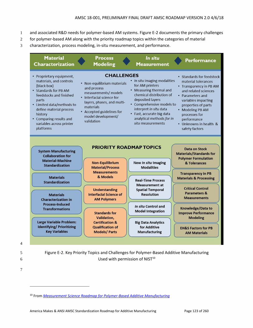
AMSC 18-001, PRELIMINARY FINAL DRAFT AMSC ROADMAP VERSION 2.0 4/6/18
America Makes & ANSI AMSC Standardization Roadmap for Additive Manufacturing Page 123 of 260
and associated R&D needs for polymer-based AM systems. Figure E-2 documents the primary challenges 1
for polymer-based AM along with the priority roadmap topics within the categories of material 2
characterization, process modeling, in-situ measurement, and performance. 3
4
Figure E-2. Key Priority Topics and Challenges for Polymer-Based Additive Manufacturing 5
Used with permission of NIST10 6
7
10 From Measurement Science Roadmap for Polymer-Based Additive Manufacturing
AMSC 18-001, PRELIMINARY FINAL DRAFT AMSC ROADMAP VERSION 2.0 4/6/18
America Makes & ANSI AMSC Standardization Roadmap for Additive Manufacturing Page 124 of 260
2.2.1.2 Storage, Handling, and Transportation 1
2
Metals11 3
In any manufacturing process, proper storage and handling of raw materials is paramount to safety and 4
the quality of the resultant product. 5
In storage, it is necessary to take steps to protect the product and limit the size of a fire or explosion. All 6
containers should be kept sealed and stored unopened in an area separate from handling areas. When a 7
container of powder is opened for loading or inspection, it should be closed and resealed as quickly as 8
possible. This not only ensures greater safety against fire from external sources, but also prevents 9
possible entrance of minor contaminants or moisture from the air. All containers in work areas should 10
be closed and sealed. Only those in actual use should be open at any time. 11
Dust generated through the handling of powders is inherently dangerous so care must be taken to store 12
and use powders in accordance with the guidelines provided by OSHA and the suppliers’ Material Safety 13
Data Sheets (MSDS or just SDS.) Applicable standards for the preparation of those MSDS may be found 14
in ANSI Z400.1/Z129.1-2010, Hazardous Workplace Chemicals - Hazard Evaluation and Safety Data Sheet 15
and Precautionary Labeling Preparation. 16
Below are some of the standardized tests that can be conducted to characterize combustibility of 17
flammable solids/powders. This is by no means a complete list. 18
ASTM E2019-03(2013), Standard Test Method for Minimum Ignition Energy of a Dust Cloud in Air 19
ASTM E1226-12a, Standard Test Method for Explosibility of Dust Clouds 20
ASTM D1929-16, Standard Test Method for Determining Ignition Temperature of Plastics 21
DOT/UN Division 4.1 - Burning Rate Test 22
DOT/UN Division 4.2 – Self-Heating Substances Test 23
The National Fire Protection Association also maintains a number of relevant standards and other 24
documents supporting the safe storage and handling of metal powders as follows: 25
NFPA 68-2018, NFPA 68 Standard on Explosion Protection by Deflagration Venting, 2018 Edition 26
NFPA 69-2014, Standard on Explosion Prevention Systems, 2014 Edition 27
NFPA 70-2017, National Electric Code (NEC) Softbound, 2017 Edition 28
NFPA 77-2014, Recommended Practice on Static Electricity, 2014 Edition 29
NFPA 91-2015, Standard for Exhaust Systems for Air Conveying of Vapors, Gases, Mists, and 30
Particulate Solids, 2015 edition 31
NFPA 499-2017, Recommended Practice for the Classification of Combustible Dusts and of 32
Hazardous (Classified) Locations for Electrical Installations in Chemical Process Areas, 2017 33
edition 34
11 This section does not discuss metal wire.
AMSC 18-001, PRELIMINARY FINAL DRAFT AMSC ROADMAP VERSION 2.0 4/6/18
America Makes & ANSI AMSC Standardization Roadmap for Additive Manufacturing Page 125 of 260
NFPA 654-2017, Standard for the Prevention of Fire and Dust Explosions from the 1
Manufacturing, Processing, and Handling of Combustible Particulate Solids, 2017 edition 2
NFPA 484-2015, Standard for Combustible Metals, 2015 Edition 3
NFPA Fire Protection Handbook, 20th Edition 4
Labeling is governed by “OSHA 29 CFR 1910.1200 for hazard communication.” Shipping is governed by 5
“CFR 49 Transportation 173.124 – Class 4, Divisions 4.1 Flammable Solid, 4.2 Spontaneously Combustible 6
Material, and 4.3 Dangerous when wet material” for combustible metal powders. Note that other 7
chemical hazardous material classifications may be present for some powders as well, such as 8
chromium. See also Code of Federal Regulations 49 Transportation in and out of the USA. 9
ISO/TC 261 and ASTM F42 are considering the need for additional standards to address safety concerns 10
specifically associated with additive manufacturing. 11
Polymers 12
Proper handling of raw material (powder, pellet, or filament) is equally important for polymers. It is 13
important to address all of the following: 14
mitigation of exposure to powder and dust; 15
emission of volatile organic chemicals (VOC) during raw material storage, delivery, pre-16
treatment, or in-process; 17
prevention of static electricity; 18
mitigation of environmental factors such as moisture and heat; 19
proper handling of powder or filament waste; and 20
exposure to nanomaterial component of specialty compound material. 21
Among the standards listed above for metals, the ones that are most relevant to polymers are ANSI 22
Z400.1/Z129.1-2010, and NFPA 654-2017. In addition, NFPA 652-2016, Standard on the Fundamentals of 23
Combustible Dust could also provide additional guidelines for proper handling of polymer dust. 24
See also Gap PC9 on environmental conditions: effects on materials. 25
2.2.1.3 Characterization of Powders 26
Ensuring that precursor materials are fit for purpose presents a need for a comprehensive 27
understanding of their chemical composition, physical morphology and structure, and mechanical, 28
thermal, and other properties relevant to the AM process and the manufactured product. 29
Characterization is often referred to as a broad and general process by which the composition, structure 30
and properties are probed and measured. This often incudes several analytical techniques 31
(spectroscopic, microscopic, macroscopic) appropriate to the type of materials and the intended 32
purpose of the study. Provided below are some of the material characteristics influencing their handling, 33
AM process steps, and the finished product quality and integrity. A list of applicable test methods to 34

AMSC 18-001, PRELIMINARY FINAL DRAFT AMSC ROADMAP VERSION 2.0 4/6/18
America Makes & ANSI AMSC Standardization Roadmap for Additive Manufacturing Page 126 of 260
obtain the material information is listed, and possible gaps in the test method development are 1
identified. 2
2.2.1.3.1 Chemical Composition 3
AM powder chemical characterization (including elemental composition, surface oxidation, chemically 4
reactive components, intermediate phases developed during the process, and trace elemental 5
impurities) is important to define the feedstock and therefore to determine the characteristics of built 6
parts. This is applicable equally for virgin and recycled feedstock for the AM process. Chemical 7
characterization may require a combination of conventional analytical methods on samples from various 8
stages in the AM process. 9
Metals 10
Equipment and standards for determining the composition of metal powders are the same as used in 11
the traditional metals industry for products such as cast/wrought mill products and powder metallurgy. 12
Nickel base and ferrous alloy powders have been produced for decades. A typical technique for 13
determining metallic element levels is X-ray spectroscopy. Residual elements often measured in part per 14
million (PPM) use mass spectrometers. Elements such as oxygen, hydrogen, and carbon use specialized 15
analyzers. All of these chemical testing processes are used worldwide. 16
Applicable standards and specifications include: 17
ASTM E322-12, Standard Test Method for Analysis of Low-Alloy Steels and Cast Irons by 18
Wavelength Dispersive X-Ray Fluorescence Spectrometry 19
ASTM E1085-16, Standard Test Method for Analysis of Low-Alloy Steels by Wavelength 20
Dispersive X-Ray Fluorescence Spectrometry 21
ASTM E572-13, Standard Test Method for Analysis of Stainless and Alloy Steels by Wavelength 22
Dispersive X-Ray Fluorescence Spectrometry 23
ASTM E353-14, Standard Test Methods for Chemical Analysis of Stainless, Heat-Resisting, 24
Maraging, and Other Similar Chromium-Nickel-Iron Alloys 25
ASTM E1019-11, Standard Test Methods for Determination of Carbon, Sulfur, Nitrogen, and 26
Oxygen in Steel, Iron, Nickel, and Cobalt Alloys by Various Combustion and Fusion Techniques 27
ASTM E2465-13, Standard Test Method for Analysis of Ni-Base Alloys by Wavelength Dispersive 28
X-Ray Fluorescence Spectrometry 29
ASTM E2594-09(2014), Standard Test Method for Analysis of Nickel Alloys by Inductively Coupled 30
Plasma Atomic Emission Spectrometry (Performance-Based Method) 31
ASTM E2823-17, Standard Test Method for Analysis of Nickel Alloys by Inductively Coupled 32
Plasma Mass Spectrometry (Performance-Based) 33
ASTM E1479-16, Standard Practice for Describing and Specifying Inductively Coupled Plasma 34
Atomic Emission Spectrometers 35
AMSC 18-001, PRELIMINARY FINAL DRAFT AMSC ROADMAP VERSION 2.0 4/6/18
America Makes & ANSI AMSC Standardization Roadmap for Additive Manufacturing Page 127 of 260
MPIF Standard Test Method 67, Guide to Sample Preparation for the Chemical Analysis of the 1
Metallic Elements in PM Materials (used for inductively coupled plasma, atomic absorption, 2
optical emission, glow discharge, and X-ray fluorescence spectrometers) 3
MPIF Standard Test Method 66, Method for Sample Preparation for the Determination of the 4
Total Carbon Content of Powder Metallurgy (PM) Materials (excluding cemented carbides) 5
MPIF Standard Test Method 06, Method for Determination of Acid Insoluble Matter in Iron and 6
Copper Powders 7
8
Applications using titanium alloy powder are emerging, and volume consumed is growing rapidly. 9
Chemical analysis techniques, like in the case of nickel base and ferrous alloys, are well established. It is 10
possible that over time revisions to procedures may be required due to the large relative surface area of 11
powder and reactivity of titanium with oxygen. However, existing specifications and standards are 12
working well. 13
Applicable standards and specifications include: 14
ASTM E539-11, Standard Test Method for Analysis of Titanium Alloys by X-Ray Fluorescnece 15
Spectrometry 16
ASTM E2371-13, Standard Test Method for Analysis of Titanium and Titanium Alloys by Direct 17
Current Plasma and Inductively Coupled Plasma Atomic Emission Spectrometry (Performance-18
Based Test Methodology) 19
ASTM E1941-10(2016), Standard Test Method for Determination of Carbon in Refractory and 20
Reactive Metals and Their Alloys by Combustion Analysis 21
ASTM E1447-09(2016), Standard Test Method for Determination of Hydrogen in Titanium and 22
Titanium Alloys by Inert Gas Fusion Thermal Conductivity/Infrared Detection Method 23
ASTM E1409-13, Standard Test Method for Determination of Oxygen and Nitrogen in Titanium 24
and Titanium Alloys by Inert Gas Fusion 25
26
Test methods used to analyse the chemical composition of aluminum include the following: 27
ASTM E34-11e1, Standard Test Methods for Chemical Analysis of Aluminum and Aluminum-Base 28
Alloys 29
ASTM E1251-17a, Standard Test Method for Analysis of Aluminum and Aluminum Alloys by Spark 30
Atomic Emission Spectrometry 31
CSN EN 14242, Aluminium and aluminium alloys - Chemical Analysis - Inductively coupled plasma 32
optical emission spectral analysis 33
Polymers 34
Specifications and standards are well established to determine molecular weight (MW) of polymers, 35
structure, chemistry of fractions, end groups, tacticity, unreacted monomer and oligomers, co-polymer 36
content and blend composition, catalyst residues, contamination analysis, chemical trace analysis and 37
polymers volatile organic compounds. It is necessary to consider the utilization of recycled materials in 38
AMSC 18-001, PRELIMINARY FINAL DRAFT AMSC ROADMAP VERSION 2.0 4/6/18
America Makes & ANSI AMSC Standardization Roadmap for Additive Manufacturing Page 128 of 260
AM applications which use thermoplastic polymer precursors to ensure their conformance to all 1
requirements. 2
NEW Gap PM8: Use of Recycled Polymer Precursor Materials. Feedstock/precursor material can be 3
sourced from either virgin polymer resin, recycled polymer resin, or a combination of the two. Recycled 4
resin can be obtained from a number of different sources including in-house processed product of the 5
same material which may not have met all the requirements when initially produced but is still 6
functional, commercial recyclate from commercial sources, and post-consumer recyclate. Recycled 7
feedstock, depending on its source and usage level, can introduce problems in the printing or end-use 8
application due to the recyclate’s thermal/mechanical history, consistency and composition. 9
R&D Needed: Yes, to determine the acceptable limits and other constraints of incorporating 10
reprocessed materials. This may be machine, material, and/or application specific. 11
Recommendation: Develop a general guidance document to address best practices in regard to sources, 12
handling, and characterization of recycled materials. In some cases, such as medical and aerospace 13
applications, more stringent guidelines may need to be developed such as identification of recycled 14
material use. 15
Priority: Low 16
Organization: ASTM F42/D20 17
2.2.1.3.2 Flowability 18
The materials used in AM are often required to flow. The performance of these materials, in regards to 19
their flowability, must be characterized. 20
Identified published standards not specific to AM include: 21
ASTM B213-17, Standard Test Methods for Flow Rate of Metal Powders Using the Hall 22
Flowmeter Funnel 23
ASTM B855-17, Standard Test Method for Volumetric Flow Rate of Metal Powders Using the 24
Arnold Meter and Hall Flowmeter Funnel 25
ASTM B964-16, Standard Test Methods for Flow Rate of Metal Powders Using the Carney Funnel 26
ISO 4490:2014, Metallic powders – Determination of flow rate by means of a calibrated funnel 27
(Hall flowmeter) 28
MPIF Standard Test Method 03, Method for Determination of Flow Rate of Free-Flowing Metal 29
Powders Using the Hall Apparatus 30
ASTM D7891-15, Standard Test Method for Shear Testing of Powders Using the Freeman 31
Technology FT4 Powder Rheometer Shear Cell 32
ASTM D1895-17, Standard Test Methods for Apparent Density, Bulk Factor, and Pourability of 33
Plastic Materials 34
Identified standards in development include: 35
AMSC 18-001, PRELIMINARY FINAL DRAFT AMSC ROADMAP VERSION 2.0 4/6/18
America Makes & ANSI AMSC Standardization Roadmap for Additive Manufacturing Page 129 of 260
Draft document ASTM WK55610, New Test Methods for the Characterization of Powder Flow 1
Properties for Additive Manufacturing Applications (formerly WK49272), being jointly developed 2
as JG 63 by ISO/TC261 and ASTM F42 3
Draft document ISO/ASTM DIS 52907, Additive Manufacturing Technical Specifications on Metal 4
Powder, being jointly developed as JG 66 by ISO/TC261 and ASTM F42 5
Gap PM1: Flowability. Existing standards for flowability do not account for the range of conditions that 6
a powder may encounter during shipment, storage, and the AM process. 7
R&D Needed: Yes. R&D is needed to measure and quantify flowability, especially with powder bed 8
processing. 9
Recommendation: Standards are needed to address test methods which encompass the variety of flow 10
regimes encountered in AM processes. Recommend completion of ASTM WK55610, New Test Methods 11
for the Characterization of Powder Flow Properties for Additive Manufacturing Applications, (not specific 12
to metal powders) which addresses dynamic flow, aeration, permeability, consolidation and 13
compressibility test procedures using for example a powder rheometer. Recommend also completion of 14
ISO/ASTM DIS 52907, Additive Manufacturing Technical Specifications on Metal Powder, which points to 15
published standards for flowability tests along with consideration of how the state of the powder would 16
affect the flowability measurement. See also Gap PC12 on precursor material flow monitoring. 17
Priority: Medium 18
Status of Progress: Green 19
Update: As noted in the text, ASTM WK55610 and ISO/ASTM DIS 52907 are in development. Completion 20
of those work items may partially but not fully address the gap. 21
Organization: ASTM F42/ISO TC 261, NIST, ASTM B09, ASTM E29 22
2.2.1.3.3 Spreadability 23
Multiple AM processes involve the spreading of powder; however, there are no AM standards specifying 24
how to quantitatively assess powder spreadability. 25
Identified standards in development include: 26
Draft document ISO/ASTM WK55610 addresses shear and dynamic flow properties but does not 27
directly address spreadability. In terms of shear properties, the draft document points to 28
existing ASTM standards for shear cell tests and wall friction tests (ASTM D6128-16, D6773-16, 29
and D7891-15). 30
Gap PM2: Spreadability. There is no known description of spreadability or standard for how to 31
quantitatively assess powder spreadability. 32
AMSC 18-001, PRELIMINARY FINAL DRAFT AMSC ROADMAP VERSION 2.0 4/6/18
America Makes & ANSI AMSC Standardization Roadmap for Additive Manufacturing Page 130 of 260
R&D Needed: Yes. R&D is needed to measure and quantify spreadability, as well as to correlate powder 1
characteristics with spreadability. 2
Recommendation: A standard should be created that guides the measurement of a powder’s 3
spreadability. This standard may be comprised of a series of tests that together describe a powder’s 4
spreading performance. 5
Priority: Medium 6
Status of Progress: Not Started, or Unknown 7
Update: There are no ASTM standard test methods for spreadability. 8
Organization: ASTM F42/ISO TC 261, NIST, universities, ASTM B09, ASTM E29 9
2.2.1.3.4 Density (Apparent vs. Tapped) 10
The powder has a large effect on the quality of a final AM part. Therefore, the loose (apparent) density 11
as well as the consolidated (tapped) density must be known. 12
Identified published standards include: 13
ISO 3923-1:2008, Metallic powders - Determination of apparent density - Part 1: Funnel method 14
ISO 3953:2011, Metallic powders - Determination of tap density 15
ASTM B527-15, Standard Test Method for Tap Density of Metal Powders and Compounds 16
ASTM B212-17, Standard Test Method for Apparent Density of Free-Flowing Metal Powders 17
Using the Hall Flowmeter Funnel 18
MPIF Standard Test Method 46, Method for Determination of Tap Density of Metal Powders 19
MPIF Standard Test Method 04, Method for Determination of Apparent Density of Free-Flowing 20
Metal Powders Using the Hall Apparatus 21
Existing standards are likely sufficient for guiding the measurement of the tapped and apparent density 22
of AM powders. No standards in development and no gaps have been identified at this time. 23
2.2.1.3.5 Particle Size and Particle Size Distribution 24
Particle size and particle size distribution are critical to the outcome of the AM build. Size of particles 25
and distribution requirements are specific to the powder deposition process and to the fusion 26
mechanism. 27
The particle size will be limited to achieve the appropriate temperature at the particle core. Particle size 28
must also be chosen appropriate to the layer thickness of the build process. While some systems allow 29
for variation in the layer thickness to accommodate various sized powders (directed energy systems 30
tend to be more flexible in terms of the layer thickness than powder bed systems), thinner layers lead to 31
better resolution. Typically, finer powders do not flow as well as those with larger particle size. 32
AMSC 18-001, PRELIMINARY FINAL DRAFT AMSC ROADMAP VERSION 2.0 4/6/18
America Makes & ANSI AMSC Standardization Roadmap for Additive Manufacturing Page 131 of 260
There are a number of measurement techniques for determining particle size, including dry sieving, laser 1
diffraction, and image analysis via optical or scanning electron microscope. 2
ASTM F3049-14, Standard Guide for Characterizing Properties of Metal Powders Used for Additive 3
Manufacturing Processes, addresses measurement techniques for particle size, making use of references 4
to existing powder size measurement methods that exist for powder metallurgy. 5
A number of applicable powder metallurgy standards exist that can be applied to AM powders. Such 6
standards include but are not limited to: 7
8
ASTM B214-16, Standard Test Method for Sieve Analysis of Metal Powders 9
ASTM B215-15, Standard Practices for Sampling Metal Powders 10
ASTM B822-17, Standard Test Method for Particle Size Distribution of Metal Powders and 11
Related Compounds by Light Scattering 12
MPIF Standard Test Method 32, Methods for Estimating Average Particle Size of Metal Powders 13
Using Air Permeability 14
ISO 9276 Parts 1-6, Representation of results of particle size analysis 15
ISO 13320:2009, Particle size analysis - Laser diffraction methods 16
Standards in development include: 17
Draft document ISO/ASTM DIS 52907, Additive Manufacturing Technical Specifications on Metal 18
Powder, being jointly developed as JG 66 by ISO/TC261 and ASTM F42 19
Gap PM3: Particle Size and Particle Size Distribution. While current standards for measurement of 20
particle size and particle size distribution exist for powder metallurgy and can be leveraged for AM 21
powders, the reliability and repeatability of different testing methodologies is currently unacceptable. 22
R&D Needed: Yes. Validation of various measurement techniques for reliability, repeatability, and 23
correlation is required, possibly defining best measurement techniques for different build systems. 24
25
Recommendation: See R&D needed. For metal PBF, recommend completion of ISO/ASTM DIS 52907, 26
Additive Manufacturing Technical Specifications on Metal Powder, which points to published standards 27
for particle size analysis and discusses advantages and limitations of each referenced test method. 28
Priority: Medium 29
Status of Progress: Green 30
Update: As noted, ISO/ASTM DIS 52907 is in development as JG 66. Completion of this work item may 31
partially but not fully address the gap. 32
Organization: ASTM F42/ISO TC 261 JG 66, ASTM B09, ASTM E29 33
2.2.1.3.6 Particle Morphology 34
AMSC 18-001, PRELIMINARY FINAL DRAFT AMSC ROADMAP VERSION 2.0 4/6/18
America Makes & ANSI AMSC Standardization Roadmap for Additive Manufacturing Page 132 of 260
Particle shape and surface quality affect flow characteristics as well as packing density. Smooth spherical 1
particles provide less resistance to flow than non-spherical particles or those with a rough surface. 2
Light scattering techniques and image analysis can be used to observe particle morphology. These 3
techniques provide a basis for qualitative comparison of powder lots. Moreover, they do not allow for 4
detection of hollow particles, which are important to detect as their presence may lead to porosity in 5
the built parts. 6
There are no AM-specific standards specifying how to quantitatively assess particle morphology. There is 7
a specification for general powder metallurgy, ASTM B243-17, Standard Terminology of Powder 8
Metallurgy, that defines typical powder shapes. ASTM B09 is planning to add AM-specific terms to B243. 9
In addition, ISO 9276 - 6:2008, Representation of results of particle size analysis – Part 6: Descriptive and 10
quantitative representation of particle shape and morphology, provides rules and nomenclature for 11
describing and quantitatively representing particle morphology. 12
Standards in development include: 13
Draft document ISO/ASTM DIS 52907, Additive Manufacturing Technical Specifications on Metal 14
Powder, being jointly developed as JG 66 by ISO/TC261 and ASTM F42 15
Gap PM4: Particle Morphology. No standards exist giving users of AM criteria for use of a particular 16
powder feedstock based on the powder morphology. 17
R&D Needed: Yes. R&D is needed to measure and quantify particle morphology. 18
Recommendation: Based on the results of R&D, a standard may be needed to define accepted test 19
methods for powder morphology and criteria for determining acceptable powder morphology 20
characteristics. Because powder morphology may affect powder flow, powder spreadability, and density 21
of the AM built object, it could possibly be addressed indirectly by standards governing flow and 22
spreadability requirements for a powder, taking into account the density of the powder. Recommend 23
completion of ISO/ASTM DIS 52907, Additive Manufacturing Technical Specifications on Metal Powder, 24
which points to published standards for describing particle morphology. 25
Priority: Low 26
Status of Progress: Green 27
Update: As noted, ISO/ASTM DIS 52907 is in development as JG 66. 28
Organization: NIST, ASTM F42/ISO TC 261 JG 66, ASTM B09, ASTM E29 29
2.2.1.3.7 Feedstock Sampling 30
Control of powder is key to obtaining consistent and predictable properties of AM objects. Metrics for 31
assessing powder characteristics depend upon testing of a representative sample. Considerations for 32
powder sampling include: 33
AMSC 18-001, PRELIMINARY FINAL DRAFT AMSC ROADMAP VERSION 2.0 4/6/18
America Makes & ANSI AMSC Standardization Roadmap for Additive Manufacturing Page 133 of 260
Methods of retrieval of a sample from a powder batch to ensure a random and representative 1
sample is taken. 2
Quantity of powder to be sampled, possibly as a function of total batch size. 3
Frequency at which to sample the powder, including how long the powder can be stored prior to 4
use before necessitating repeat sampling. 5
Requirements for sampling of reused powder and of blends/mixtures of different powder 6
batches, in the case where the original powders were sampled. See also section 2.2.2.7 on 7
precursor material handling: use, re-use, mixing, and recycling powder. 8
In terms of published standards, there are: 9
ISO 3954:2007, Powders for powder metallurgical purposes—Sampling 10
ASTM B215-15, Standard Practices for Sampling Metal Powders 11
ASTM F3049-14, Standard Guide for Characterizing Properties of Metal Powders Used for 12
Additive Manufacturing Processes, which references existing powder metallurgy sampling 13
practices covered in ASTM B215 14
MPIF Standard Test Method 01, Method for Sampling Metal Powders (2016), which has 15
similarities to ASTM B215 16
In terms of standards in development, SAE AMS7001, Nickel Alloy, Corrosion and Heat-Resistant, Powder 17
for Additive Manufacturing, 62Ni - 21.5Cr - 9.0Mo - 3.65 Nb deals with this issue. 18
Gap PM5: Metal Powder Feedstock Sampling. While existing powder metallurgy standards may be 19
leveraged for AM use, they require tailoring for AM-specific situations. For example, sampling practices 20
for reused powder that has been through an AM build cycle are needed to establish how to collect 21
representative powder samples. These practices should take into account the variation caused by build 22
exposure on powder in multiple locations. 23
R&D Needed: Yes, with respect to the re-use of powder during the build. See also Gaps PC7, PC10 and 24
PC11. 25
Recommendation: Standards are needed for sampling of powders used for AM, with considerations for 26
unique aspects of AM not considered in powder sampling standards for general powder metallurgy, 27
including re-use of powder. 28
Priority: High 29
Status of Progress: Green 30
Update: SAE AMS7001, Nickel Alloy, Corrosion and Heat-Resistant, Powder for Additive Manufacturing, 31
62Ni - 21.5Cr - 9.0Mo - 3.65 Nb is in development and addresses this issue. For metals specifically, 32
members of MPIF's Association for Metal Additive Manufacturing (AMAM) technical committee 33
AMSC 18-001, PRELIMINARY FINAL DRAFT AMSC ROADMAP VERSION 2.0 4/6/18
America Makes & ANSI AMSC Standardization Roadmap for Additive Manufacturing Page 134 of 260
reviewed MPIF Standard Test Method 01, Method for Sampling Metal Powders (2016) and noted that 1
challenges with standardizing powder sampling include variations for different powder alloy systems, 2
additive manufacturing technologies, and the importance of powder purity to the application. ASTM B09 3
is currently reviewing the MPIF Std. Test Method 01. For polymers, there may be interest from ASTM 4
D20 working in conjunction with ASTM F42. 5
Organization: NIST, SAE AMS-AM, ASTM B09, MPIF, ASTM D20 (for polymers), ASTM F42, ASTM E29 6
2.2.1.3.8 Hollow Particles and Hollow Particles with Entrapped Gas 7
The fitness-for-use requirements of metal powders for additive manufacturing differ from traditional 8
metal powder applications. One area is the potential impact of the presence of hollow particles and 9
hollow particles with entrapped gas that occurred during the atomization process. Hollow particles and 10
hollow particles with entrapped gas may exist in metal powder lots regardless of the powder making 11
and atomization processes and therefore may be an uncontrolled variable. 12
In terms of published standards, there are: 13
ASTM B922-17, Standard Test Method for Metal Powder Specific Surface Area by Physical 14
Adsorption 15
ASTM B311-17, Test Method for Density of Powder Metallurgy (PM) Materials Containing Less 16
Than Two Percent Porosity 17
ISO 13947:2011, Metallic powders - Test method for the determination of non-metallic inclusions 18
in metal powders using a powder-forged specimen 19
ASTM B796-14, Standard test method for Nonmetallic Inclusion Content of Ferrous Powders 20
Intended for Powder Forging (PF) Applications 21
ASTM B923-10, Standard Test Method for Metal Powder Skeletal Density by Helium or Nitrogen 22
Pycnometry 23
The above standards do not address the measurement of powder inclusions or closed porosity 24
measurements for AM specific applications. 25
The following methods are currently used in R&D to determine internal powder porosity: 26
Gas and liquid pycnometry – Measurement of True Density of powders. Method suitable for 27
powders where a large fraction of the population has porosity. Also, suitable for single element 28
composition exact mixtures. Variation in alloy composition decreases measurement accuracy. 29
Do not obtain pore size distribution. 30
Metallography with image analysis – Suitable for powder where a large fraction of the 31
population has porosity. Limited by large number of measurements needed for accurate 32
statistics. 33
CT with image analysis – Bulk analysis for powder porosity. 34
Ultrasonic Non-Destructive Testing (NDT) – Suitable for bulk materials. Development of 35
experimental database for powder is needed. 36
AMSC 18-001, PRELIMINARY FINAL DRAFT AMSC ROADMAP VERSION 2.0 4/6/18
America Makes & ANSI AMSC Standardization Roadmap for Additive Manufacturing Page 135 of 260
Research of powder porosity measurement techniques conducted at NIST, industrial labs, universities. 1
There are no ASTM, ISO, or MPIF standards for measuring internal powder porosity/inclusions for AM 2
specific applications. 3
Gap PM6: Hollow Particles and Hollow Particles with Entrapped Gas. No standards exist for measuring 4
how to determine the presence and percentage of hollow particles and hollow particles with entrapped 5
gas or their impact upon part properties and in-service performance. 6
R&D Needed: Yes. R&D is needed to establish the impact of hollow powder particles, if any. 7
Recommendation: Dependent upon R&D, a standard may be needed that specifies how to determine 8
the percentage of hollow particles and hollow particles with entrapped gas in lots of metal powders. 9
Testing may be needed to determine the level of hollow particles and hollow particles with entrapped 10
gas that are acceptable without negatively affecting the properties and performance of finished parts. 11
Recommend completion of ISO/ASTM DIS 52907, Additive Manufacturing Technical Specifications on 12
Metal Powder and include measurement standards for powder internal porosity. 13
Priority: Low 14
Status of Progress: Unknown 15
Update: No update provided. 16
Organization: For R&D: NIST, ASTM, America Makes, Oak Ridge National Laboratory, universities. For 17
standards: ASTM F42/ISO TC 261, SAE, ASTM B09, ASTM E29 18
2.2.1.3.9 AM Process-Specific Metal Powder Specifications 19
Currently, most manufacturers of AM equipment also offer metal powder for purchase. In fact, they 20
provide data containing representative final material properties for parts created using both their 21
equipment and powder. However, there is a need for a specification to procure and accept metal 22
powder so that compliance can be independently verified. 23
No AM metal powder standards have been identified. SAE AMS-AM is developing AM powder standards 24
for aerospace applications including SAE AMS7001, Nickel Alloy, Corrosion and Heat-Resistant, Powder 25
for Additive Manufacturing, 62Ni - 21.5Cr - 9.0Mo - 3.65 Nb. In addition, ASTM F42 subcommittees for 26
test methods (F42.01) as well as materials and processes (F42.05) are working in this area, having 27
developed a draft (standard guide for creating feedstock specifications for metal powder bed fusion) 28
that will most likely become a joint ISO/ASTM deliverable. 29
Gap PM7: AM Process-Specific Metal Powder Specifications. There is a need to develop AM process-30
specific metal powder specifications to ensure that a competitive supply of metal powder is available for 31
procurement purposes. Further, vendors should be encouraged to use these industry powder 32
specifications when testing their equipment and advertising final material properties. 33
AMSC 18-001, PRELIMINARY FINAL DRAFT AMSC ROADMAP VERSION 2.0 4/6/18
America Makes & ANSI AMSC Standardization Roadmap for Additive Manufacturing Page 136 of 260
R&D Needed: Yes. R&D is needed to determine the effect of powder parameters/characteristics on final 1
part properties and on the suitability of a given powder for use in a given AM machine. Some of these 2
powder parameters may include: 3
1) Particle Size Distribution 4
2) Particle Morphology 5
3) Flow Rate 6
4) Tap Density 7
5) Angle of Repose 8
6) Shear Stress 9
7) Chemistry 10
8) Specific Surface Area 11
12
Recommendation: Develop AM process-specific metal powder specifications to facilitate procurement 13
of metal powders for use in AM machines. These specifications should describe the acceptable ranges of 14
all relevant powder parameters that would impact the suitability of a given powder to be used in a given 15
AM machine, and the effect it would have on final material properties. 16
Priority: Medium 17
Status of Progress: Green 18
Update: ASTM WK58219, New Guide for Additive Manufacturing - Feedstock Materials-Creating 19
Feedstock Specifications for Metal Powder Bed Fusion, is in development. SAE AMS7001, Nickel Alloy, 20
Corrosion and Heat-Resistant, Powder for Additive Manufacturing, 62Ni - 21.5Cr - 9.0Mo - 3.65 Nb, has 21
some of the parameters defined. As of January 8, 2018, a fourth ballot on SAE AMS7001 has closed and 22
work is underway to resolve the comments. 23
Organization: ISO/ASTM, SAE AMS-AM, AWS, industry OEMs 24
2.2.1.4 Characterization of Material Extrusion Feedstock (Filaments & Pellets) 25
Filaments are produced by extruding plastic pellets or powders (generally derived from ground pellets) 26
into the appropriate filament geometry required for the AM process in which the filaments are 27
reheated, melted, and deposited onto the build. Pellet feedstock for AM processing is a variant which 28
eliminates the need to produce filaments and relies on the direct feeding, heating, and melting of the 29
plastic as part of the AM process. In most cases, these are fully formulated materials containing 30
appropriate stabilizers and other components as required. The chemical requirements for filament 31
feedstock and pellet feedstock could be identical but the physical requirements are different. 32
2.2.1.4.1 Chemical Composition 33
Chemical characterization (including composition, molecular weight (MW) of polymers, chemical 34
structure, co-polymer content and blend composition, impurity content, formulation, and polymers 35
volatile organic compounds) is important to define the feedstock and therefore to determine the 36
AMSC 18-001, PRELIMINARY FINAL DRAFT AMSC ROADMAP VERSION 2.0 4/6/18
America Makes & ANSI AMSC Standardization Roadmap for Additive Manufacturing Page 137 of 260
characteristics of built parts. This is applicable equally for virgin and recycled feedstock for the AM 1
process, see gap PM8. 2
Applicable standards and specifications include: 3
ASTM D4000, Standard Classification System for Specifying Plastic Materials 4
Specific ASTM Material classification documents (per D4000), for example: 5
ASTM D6779-17, Standard Classification System for and Basis of Specification for Polyamide 6
Molding and Extrusion Materials (PA) 7
ASTM D4101-17, Standard Classification System and Basis for Specification for Polypropylene 8
Injection and Extrusion Materials 9
Standards in development include: 10
SAE AMS7101, Material for Fused Filament Fabrication 11
2.2.1.4.2 Geometry 12
The geometry of the filament or pellets can affect how well the material will process and can affect the 13
final AM part density and fill, as well as potential for defects. The geometry needed is very dependent 14
and will be defined by the individual OEM machine. 15
2.2.1.4.3 Melt Flow 16
The materials used in material extrusion are required to melt and flow through a nozzle to be deposited 17
on the build. The performance of these materials, in regards to their flow, must be characterized. They 18
are typically characterized by their rheological (melt) and thermal properties. 19
Applicable standards and specifications include: 20
ASTM D1238-13, Standard Test Method for Melt Flow Rates of Thermoplastics by Extrusion 21
Plastometer 22
ASTM D3418-15, Standard Test Method for Transition Temperatures and Enthalpies of Fusion 23
and Crystallization of Polymers by Differential Scanning Calorimetry 24
ASTM D4440-15, Standard Test Method for Plastics: Dynamic Mechanical Properties Melt 25
Rheology 26
ASTM D7028-07(2015), Standard Test Method for Glass Transition Temperature (DMA Tg) of 27
Polymer Matrix Composites by Dynamic Mechanical Analysis (DMA) 28
Standards in development include: 29
SAE AMS7101, Material for Fused Filament Fabrication 30
AMSC 18-001, PRELIMINARY FINAL DRAFT AMSC ROADMAP VERSION 2.0 4/6/18
America Makes & ANSI AMSC Standardization Roadmap for Additive Manufacturing Page 138 of 260
2.2.1.4.4 Moisture Content 1
The moisture content of the material extrusion feedstock must be characterized. Moisture within the 2
feedstock has a large effect on potential defects within the AM part. 3
Applicable standards and specifications include: 4
ASTM D7191, Standard Test Method for Determination of Moisture in Plastics by Relative 5
Humidity Sensor 6
ASTM D6980, Standard Test Method for Determination of Moisture in Plastics by Loss in weight 7
Standards in development include: 8
SAE AMS7101, Material for Fused Filament Fabrication 9
2.2.1.4.5 Thermal Stability 10
Since these processes involve exposure to elevated temperatures in their production and in the melting 11
or softening of the material in the AM process, the thermal stability is critical as excessive temperatures 12
or exposure times can result in degradation and changes in the composition and material properties. 13
Applicable standards and specifications include: 14
ASTM D3895, Standard Test Method for Oxidative-Induction Time of Polyolefins by Differential 15
Scanning Calorimetry 16
ASTM D3012, Standard Test Method for Thermal-Oxidative Stability of Polypropylene Using a 17
Specimen Rotator Within an Oven 18
NEW Gap PM9: Characterization of Material Extrusion Feedstock (Filaments & Pellets). There are many 19
classification systems and test procedures that are available and applicable to characterizing the 20
feedstocks used for filaments or pellets. However, these are based on “conventional” processes and 21
requirements and, in many cases, will need to be adapted to AM requirements and, in some cases, new, 22
more specific systems and procedures may be required. 23
R&D Needed: Yes, to define the specific requirements and evaluate if these can be addressed by existing 24
systems and procedures and, if not, to develop new ones. 25
Recommendation: Since this will be very dependent on specific materials and process requirements, 26
existing documents need to be evaluated on a case-by-case basis and, if necessary, new documents 27
need to be developed. This is another aspect that needs to be considered by a possible ASTM F42 and 28
D20 collaboration. 29
Priority: Low 30
Organizations: ASTM F42/D20 31
AMSC 18-001, PRELIMINARY FINAL DRAFT AMSC ROADMAP VERSION 2.0 4/6/18
America Makes & ANSI AMSC Standardization Roadmap for Additive Manufacturing Page 139 of 260
2.2.1.5 Characterization of Liquid Feedstock 1
Liquid Feedstock is often produced by mixing a variety of monomers, oligomers, initiators, pigments, 2
stabilizers, etc. These materials are chemically reactive and need to be careful characterized to ensure 3
the liquid feedstock has not begun to react and is still viable to be use within the additive manufacturing 4
process. 5
2.2.1.5.1 Chemical Composition 6
Chemical characterization (including composition, molecular weight (MW) of oligomers, chemical 7
structure, and impurity content) is important to define the feedstock and therefore to determine the 8
characteristics of built parts. Specifications and standards are well established to determine molecular 9
weight (MW), structure, end groups, and degree of conversion. 10
2.2.1.5.2 Viscosity 11
The viscosity of the liquid feedstock is extremely important to how well the material can be processed 12
through the specific AM technique (SLA or Material Jetting). It is often monitored throughout the 13
process to indicate the liquid precursor health. Large changes in the viscosity can indicate a change in 14
chemical composition (material be slowly polymerized, filler content increasing of stratifying) and can 15
affect how well the material is processed, the final AM part density and mechanical strength. 16
Characterization may require samples from various stages in the AM process. 17
Identified published standards not specific to AM include: 18
ASTM D4212-16, Standard Test Method for Viscosity by Dip-Type Viscosity Cups 19
ASTM D1084-16, Standard Test Methods for Viscosity of Adhesives 20
2.2.1.5.3 Feedstock Sampling 21
Control of liquid feedstock is key to obtaining consistent and predictable properties of AM objects. 22
Metrics for assessing liquid material characteristics especially in an open system depend upon testing of 23
a representative sample. Considerations for liquid sampling include: 24
Methods of retrieval of a sample to ensure a random and representative sample is taken. 25
Quantity of liquid to be sampled, possibly as a function of total batch size. 26
Frequency at which to sample the liquid, including how long the liquid can be stored or in use 27
before necessitating repeat sampling. 28
NEW Gap PM10: Sampling of Open Liquid Feedstock System. There is a need to develop a standard for 29
monitoring and sampling open liquid feedstock systems to ensure the consistent chemical composition 30
and mechanical properties in the final AM part. 31
AMSC 18-001, PRELIMINARY FINAL DRAFT AMSC ROADMAP VERSION 2.0 4/6/18
America Makes & ANSI AMSC Standardization Roadmap for Additive Manufacturing Page 140 of 260
R&D Needed: Yes. R&D is needed to determine how much the viscosity can change before having a 1
significant effect on the mechanical and chemical properties of the final AM part, how fast the change 2
can happen and the frequency and method for sampling the open liquid feedstock system. 3
Recommendation: Develop a process-specific standard to indicate how often the liquid feedstock 4
viscosity must be monitored throughout the feedstock’s lifetime (both in storage and in an open 5
system). 6
Priority: Low 7
Organization: ISO/ASTM, Industry OEMs 8
2.2.2 Process Control 9
2.2.2.1 Introduction 10
11
Process control in AM is a broad and significant topic. For purposes of this document, process control 12
refers to the control of variables that affect the quality of parts fabricated via AM. These variables are 13
encountered in every step of the AM process, including creation and control of the 3D part model, 14
selection and characterization of feedstock material, operator training, selection of machine parameters 15
used for the part build, calibration and maintenance of equipment, and part post-processing. Control of 16
such a wide range of variables is particularly important in the AM industry because inspection 17
techniques that are commonly used to verify part quality can be challenging to apply to AM parts and 18
must be taken into consideration when factoring in the qualification of a given component. This section 19
discusses various aspects of AM process control and describes the standards that already exist or that 20
are needed to ensure that acceptable AM parts can be repeatedly fabricated. Operator training and 21
qualification is addressed in the Qualification and Certification section. 22
Existing process control standards include the following: 23
ASTM F3091/F3091M-14, Standard Specification for Powder Bed Fusion of Plastic Materials 24
AWS D17.1/D17.1M:2010-AMD1, Specification for Fusion Welding for Aerospace Applications - 25
AMD 26
ASTM F3187-16, Standard Guide for Directed Energy Deposition of Metals 27
Process control standards in development include: 28
ISO/ASTM PWI 52904, Additive Manufacturing – Process Characteristics and Performance: 29
Standard Practice for Metal Powder Bed Fusion Process to Meet Critical Applications, being 30
developed by ISO/TC 261 and ASTM F42 as JG 56), previously ASTM WK60906. 31
ISO/ASTM CD 52903-2, Additive manufacturing -- Standard specification for material extrusion 32
based additive manufacturing of plastic materials -- Part 2: Process -- Equipment 33
SAE AMS7003 WIP, Laser Powder Bed Fusion Process 34
AWS D20.1, Standard for Fabrication of Metal Components using Additive Manufacturing 35
AMSC 18-001, PRELIMINARY FINAL DRAFT AMSC ROADMAP VERSION 2.0 4/6/18
America Makes & ANSI AMSC Standardization Roadmap for Additive Manufacturing Page 141 of 260
ASME XXX-2019, Use of Additive Manufacturing for Pressure Retaining Equipment. Guideline 1
standard under development by ASME with publication expected in 2019 to address 2
manufacture of pressure retaining equipment using the additive manufacturing process. This 3
“guide” is intended to initially address the use of laser and electronic beam powder bed fusion 4
to fabricate parts and items with emphasis on the final product produced using these two 5
processes and the evaluation of the material properties of the finished product. 6
2.2.2.2 Digital Format and Digital System Control 7
Process control of digital format throughout CAD, CAM, and additive programming systems is critical to 8
maintain production quality. In the event of software revisions and upgrades, the complexity of the 9
systems requires the user to confirm that parts produced maintain the same level of quality: form, fit, 10
and function/material properties. Inexperienced operators may not be aware of automated or OEM 11
installed system upgrades and may assume status quo when restarting operations. 12
13
Published standards include ISO/ASTM 52915:2016, Specification for Additive Manufacturing File Format 14
(AMF) Version 1.2. 15
Gap PC1: Digital Format and Digital System Control. Existing process control standards do not 16
adequately address digital format and digital system control. 17
R&D Needed: Yes 18
Recommendation: Leverage NIST research and work with SDOs to ensure that AM process control 19
standards include digital format and digital system control. 20
Priority: Medium 21
Status of Progress: Green 22
Update: The ISO/TC 261/ASTM F42 JG 56 standard in development addresses digital data configuration 23
control. 24
Organization: NIST, ISO/ASTM JG 56, SAE, IEEE-ISTO PWG 25
2.2.2.3 Machine Calibration and Preventative Maintenance 26
Machine calibration and preventative maintenance can impact output quality and requires periodic 27
measurement in addition to any OEM maintenance that is as critical as software revision control. Users 28
must confirm that an AM machine continues to generate products meeting all quality requirements 29
after maintenance is performed. For example, the requalification process can range between a full first 30
article to a subset thereof and may include metallographic analysis. 31
Additionally, routine maintenance and performance checks of machine components vary between OEMs 32
and are often not open to the end user. Standard tests of machine components, however, can allow end 33
AMSC 18-001, PRELIMINARY FINAL DRAFT AMSC ROADMAP VERSION 2.0 4/6/18
America Makes & ANSI AMSC Standardization Roadmap for Additive Manufacturing Page 142 of 260
users to regularly assess machine performance. This will create confidence that a machine is functioning 1
as expected and allow the end user to alert the OEM of required maintenance prior to build failures. 2
Research is required to determine how, and at what magnitude, errors in machine components affect 3
output quality so that machine calibration and preventative maintenance checks with appropriate 4
tolerances can be developed. For example, the motion control components are trusted to provide 5
accurate positioning. Scanner calibration, which measures galvanometer-driven mirror performance, is 6
currently performed at installation of the machine by the OEM and not all OEMs perform this test and 7
calibration at the time of maintenance. Errors in the scanner system can lead to reductions in build 8
quality and, at a minimum scanner calibration should be performed annually. The OEMs currently will 9
not allow users to calibrate the scanner, but measuring a standardized test could quantify any changes 10
and flag when a calibration would be needed. In addition to the scanner calibration, “fine tuning” may 11
address this requirement. Fine tuning is a quick build that is run to check many different inputs from 12
process parameters. After measuring the “fine tuning” build, adjustments could be made or the OEM 13
could be alerted of required adjustments to improve the quality of the builds that follow. 14
This issue is closely linked to digital format and digital system control, and machine qualification. See 15
also section 2.5.2 on maintenance and sustainment of machines. 16
No published standards have been identified. 17
Standards in development include: 18
The draft standard AWS D20.1, Standard for Fabrication of Metal Components using Additive 19
Manufacturing, contains placeholders for machine calibration and preventative maintenance 20
requirements. 21
22
ASTM WK58231, Additive Manufacturing - Creating Maintenance Schedules and Maintaining 23
Metal Powder Bed Fusion Machines 24
The ISO/TC 261/ASTM F42/JG 56 standard in development addresses periodic preventive 25
maintenance. In addition, ASTM F42.01 and ISO jointly have about five artifacts in one standard, 26
ASTM WK55297, New Guide for Additive Manufacturing -- General Principles -- Standard Test 27
Artefacts for Additive Manufacturing, that is nearing completion and that can be used for 28
machine calibration and maintenance. ISO/ASTM 52910-17, Standard Guidelines for Design for 29
Additive Manufacturing, is also applicable. 30
SAE AMS7100, Fused Filament Fabrication Process, includes requirements for machine 31
calibration procedures and preventative maintenance plans for the Fused Deposition Modeling 32
process (polymer process). 33
SAE AMS7003, Laser Powder Bed Fusion Process, includes requirements for a machine 34
calibration and verification plan as well as an Appendix listing minimum measurement elements 35
(metallic process). 36
AMSC 18-001, PRELIMINARY FINAL DRAFT AMSC ROADMAP VERSION 2.0 4/6/18
America Makes & ANSI AMSC Standardization Roadmap for Additive Manufacturing Page 143 of 260
Gap PC2: Machine Calibration and Preventative Maintenance. There are no known industry standards 1
addressing machine calibration and preventative maintenance for additive manufacturing. Current users 2
may not have established best practices or their own internal standards and may assume that the OEM 3
maintenance procedures are sufficient to start/restart production. Additionally, AM machines have 4
many mechanical components that are similar to conventional subtractive machinery. The motion 5
control components are trusted to provide accurate positioning and it is currently unknown how errors 6
in these systems affect the output quality. This is important during machine qualification and could be 7
addressed in a standard. 8
R&D Needed: Yes. Research is required to determine how errors in machine components affect output 9
quality so that tolerances can be developed for machine calibration and preventative maintenance 10
checks 11
Recommendation: Complete work on standards in development addressing machine calibration and 12
preventative maintenance. In addition, OEM and end user best practices should ensure adequate and 13
recommended calibration and maintenance intervals that have been documented with data for 14
different processes and machines. OEMs and SDOs should develop technical reports that incorporate 15
case studies related to machine restart after maintenance. Standards should account for motion control 16
components that guide measurement and remediation of error in positioning systems where possible in 17
AM machines. OEMs should also take this into account when designing AM machines. 18
Priority: High. There is an urgent need to develop guidelines on day-to-day machine calibration checks. 19
Status of Progress: Green 20
Update: As noted in the text. 21
Organization: AWS D20, ASTM F42/ISO TC 261, SAE AMS-AM, NIST, OEMs, end users, experts in 22
machine metrology 23
24
Gap PC3: Machine Health Monitoring. There are no known industry standards addressing AM machine 25
health monitoring. Machine health monitoring is a process of observing the machinery to identify 26
changes that may indicate a fault. The use of a machine health monitoring system allows maintenance 27
to be scheduled in a timely manner so as to prevent system failure. 28
R&D Needed: Yes 29
Recommendation: Adapt existing health monitoring (diagnostics and prognosis) standards for use in the 30
additive manufacturing industry. Examples of such standards are the semiconductor industry “Interface 31
A” collection of standards and ISO 13379-1:2012, Condition monitoring and diagnostics of machines - 32
Data interpretation and diagnostics techniques - Part 1: General guidelines and ISO 13381-1:2015, 33
Condition monitoring and diagnostics of machines - Prognostics - Part 1: General guidelines. Additional 34
information can be found in NISTIR 8012, Standards Related to Prognostics and Health Management 35
AMSC 18-001, PRELIMINARY FINAL DRAFT AMSC ROADMAP VERSION 2.0 4/6/18
America Makes & ANSI AMSC Standardization Roadmap for Additive Manufacturing Page 144 of 260
(PHM) for Manufacturing.12 Further research/guidelines/specifications may be needed. For example, 1
NIST may be able to identify critical indicators that need to be documented or controlled to assist end 2
users with quality assurance. See also Gap M6, Tracking Maintenance. 3
Priority: Low 4
Status of Progress: Not Started, or Unknown 5
Update: ASME has a non AM specific project concerning Advanced Monitoring, Diagnostics, and 6
Prognostics for Manufacturing Operations. 7
Organization: NIST, ISO, ASTM, AWS, IEEE-ISTO PWG, ASME 8
9
2.2.2.4 Machine Qualification 10
To produce reproducible AM builds, it is necessary to ensure that the machine doing the build be 11
qualified. 12
Published Standards 13
MSFC-STD-3716, Standard for Additively Manufactured Spaceflight Hardware by Laser Powder 14
Bed Fusion in Metals 15
MSFC-SPEC-3717, Specification for Control and Qualification of Laser Powder Bed Fusion 16
Metallurgical Processes 17
Standards in Development 18
The draft AWS D20.1 document does not currently have specific requirements for machine 19
“qualification.” However, it does identify machine model, serial number, and software versions 20
as variables that are essential to the AM procedure qualification (i.e., if the software is 21
upgraded, the AM procedure must be re-qualified using the new software version). Additionally, 22
based on the category (i.e., criticality) of the part, the draft AWS D20.1 requires the fabrication 23
of witness specimens along with each part build cycle to be tested to ensure that the machine is 24
performing as expected. 25
For metals, SAE AMS7003, Laser Powder Bed Fusion Process, includes requirements for machine 26
calibration and machine approval. For polymers, SAE AMS7100, Fused Filament Fabrication 27
Process, includes requirements for machine calibration procedures and preventative 28
maintenance plans for the Fused Deposition Modeling process (applicable to ULTEM 9085 and 29
ULTEM 1010). 30
ASTM WK58226 IQ, OQ and PQ 31
ASTM WK58232, Calibrating Machines and Subsystems 32
12 http://dx.doi.org/10.6028/NIST.IR.8012
AMSC 18-001, PRELIMINARY FINAL DRAFT AMSC ROADMAP VERSION 2.0 4/6/18
America Makes & ANSI AMSC Standardization Roadmap for Additive Manufacturing Page 145 of 260
ASTM WK58223, Additive Manufacturing - Post Thermal Processing of Metal Powder Bed Fusion 1
Parts 2
NAVSEA is currently drafting a PBF specification that will address machine qualification as part 3
of the manufacturing process prior to first article and production of a component or part. 4
Gap PC4: Machine Qualification. Current users may not have considered the influence of machine 5
control on resulting product quality and material properties beyond form and fit, including machine-to-6
machine variation (even between machines of the same make and model). While guidelines for machine 7
qualification can be developed, a broader view of part-specific, process-specific, material-specific, and 8
application-specific recommended practices is needed. 9
R&D Needed: Yes 10
Recommendation: SDOs should develop qualification standards for AM machines to pass in order to 11
provide a level of confidence that these machines can produce parts with the required material 12
properties. In addition, SDOs should develop guidelines or technical reports that incorporate case 13
studies of various part types and applications across materials. Additional research may be needed in 14
relation to machine-to-machine variation and on key parameters. 15
Priority: Medium 16
Status of Progress: Green 17
Update: As noted in the text. 18
Organization: NIST, AWS, SAE AMS-AM, ASTM F42, NAVSEA, NASA MFSC 19
2.2.2.5 Parameter Control 20
Parameter control is integrally linked to software, maintenance, and machine qualification protocols. 21
Parameters are typically controlled through software but also require that calibrations be within 22
periodic measurement to ensure part quality. 23
Variability within and among AM parts has been widely reported in the AM industry. Variability has been 24
noted among parts with different inter-layer (i.e., interpass) times, along the z-direction within a single 25
part, within a part that contains features of varying thickness, among parts built in different locations on 26
the same build platform, among parts built with different surroundings on the build platform, between 27
as-built and machined parts, and between parts built with different AM machines of the same model. 28
Most material property variability within and among AM parts is the result of varying thermal histories 29
and their effect on local material microstructures and defect formation. 30
As has been widely noted in the AM industry, there are a vast number of process parameters that are 31
either programmed by the operator via AM machine software or are controlled by the AM machine 32
without operator input. In some instances, AM machines are manufactured such that the buyer cannot 33
know or control all of the process parameters. This is an intellectual property (IP) issue that provides a 34
AMSC 18-001, PRELIMINARY FINAL DRAFT AMSC ROADMAP VERSION 2.0 4/6/18
America Makes & ANSI AMSC Standardization Roadmap for Additive Manufacturing Page 146 of 260
barrier to the full understanding of the effects of process parameters on AM part performance. 1
Additionally, many AM part producers treat process parameters that they have developed as IP in order 2
to maintain a competitive advantage in the AM industry. 3
No published standards have been identified. 4
AWS D20.1 is drafting extensive lists of process parameters that must be controlled for a variety of 5
metal AM processes. These processes include laser and electron beam powder bed fusion, and laser, 6
electron beam, and arc directed energy deposition. The acceptability of the process parameters will be 7
required to be demonstrated through the fabrication and testing of procedure qualification test pieces. 8
Changes to the process parameters outside of a qualified range will require full or partial requalification 9
of the AM procedure. This philosophy is analogous to welding procedure qualification requirements. 10
Gap PC5: Parameter Control. As a result of the many sources of variability within and among AM parts, 11
and because a complete understanding of the specific effects of so many build process parameters on 12
AM part performance is not currently available in the AM industry, standards are needed to identify 13
requirements for demonstrating that a set of build process parameters produces an acceptable part, 14
and for ensuring that those build process parameters remain consistent from build to build. 15
R&D Needed: Yes. Develop and establish one verifiable key process parameter that combines both 16
material and process parameters (such as power absorption coefficient or power ratio parameter, 17
verifiable by melt pool geometry, shown in the research) that is independent of material and machine 18
brand. R&D is needed to verify the concept of power ratio as the single controlling parameter and its 19
applicability to all materials and machine brands. 20
Recommendation: Develop a standard that identifies key build process parameters for AM machines, 21
taking into account the different processes, materials, industry-specific applications, and machines 22
involved. Complete work on AWS D20.1. See also Gap QC3 on harmonizing Q&C terminology for process 23
parameters. 24
Priority: Medium 25
Status of Progress: Green 26
Update: As noted in the text, AWS D20.1 is being developed. ASTM F42 process and materials standards 27
cover the parameters for PBF and Inconel 625 but not the values. SAE AMS7100 is trying to address FDM 28
process control including setting parameters for the aerospace industry. SAE AMS7003 includes an 29
appendix on PBF-L process characteristics but contains no values. 30
Organization: AWS D20, ASTM F42, SAE AMS-AM, OEMs, IEEE-ISTO PWG 31
2.2.2.6 Adverse Machine Environmental Conditions: Effect on Component Quality 32
AM machines may be used in environments where they are subject to vibration, minor seismic activity, 33
roll and pitch (e.g., shipboard), or gradients in temperature and pressure. AM machines need to be 34
AMSC 18-001, PRELIMINARY FINAL DRAFT AMSC ROADMAP VERSION 2.0 4/6/18
America Makes & ANSI AMSC Standardization Roadmap for Additive Manufacturing Page 147 of 260
qualified not only for the manufacture of a set population of parts, but to operate in the requisite 1
environment. For example, a machine could be resident in a plant where other machines are constantly 2
in operation or heavy trucks drive past. The vibrations that could carry through structures and/or the 3
floor/ground need to be sufficiently mitigated during manufacturing. Otherwise, the machine should 4
only be used when those types of adverse factors are not present. The final product must not be 5
adversely impacted due to environmental conditions. 6
For the defense industry, the forwardly deployed environment (e.g., in theatre or shipboard) has unique 7
impacts on AM processes that are not fully understood at this point. Usage of AM machines for these 8
environments needs to be performed by or under the guidance of qualified AM operators and machines. 9
Gap PC6: Adverse Machine Environmental Conditions: Effect on Component Quality. There is a need 10
for more research as well as standards or specifications that address AM machines being able to work in 11
adverse environmental conditions. 12
R&D Needed: Yes 13
Recommendation: Develop standards and specifications to address external environmental factors that 14
could negatively impact component quality. 15
Priority: Low 16
Status of Progress: Unknown 17
Update: None provided. 18
Organization: OEMs, DoD for military-specific operational environments, ASTM 19
2.2.2.7 Precursor Material Handling: Use, Re-use, Mixing, and Recycling Feedstock 20
Handling of feedstock materials during the manufacturing process must be controlled to minimize, if not 21
eliminate, the risk of contamination and product defects. Storage and shipment of feedstock material 22
should also meet the precursor material requirements and keep these properties along its shelf life. 23
Mixing and re-use of materials must meet the precursor material requirements. Similarly, handling of 24
unused material is a critical enabler for product quality and re-use or recycle in subsequent additive part 25
production. One cannot assume that material at the end of an additive process meets precursor 26
material requirements or is otherwise qualified for production. See also section 2.2.1.3.7 on feedstock 27
sampling. 28
Regarding precursor material handling, specifically terminology, ISO/ASTM 52900:2015, Additive 29
manufacturing – General principles – Terminology, contains the following terms and definitions: 30
Material supplier; Feedstock; Part cake; Powder batch; Powder blend; Powder lot; Used powder; and 31
Virgin powder. No other published standards or standards in development have been identified. 32
AMSC 18-001, PRELIMINARY FINAL DRAFT AMSC ROADMAP VERSION 2.0 4/6/18
America Makes & ANSI AMSC Standardization Roadmap for Additive Manufacturing Page 148 of 260
Gap PC7: Recycle & Re-use of Materials. There are many practices in the materials industry of how to 1
recycle, re-use, and revert materials in production. They are also highly material dependent. End users 2
need to understand best practices for how to qualify their various precursor material streams. 3
R&D Needed: Yes. Research should be conducted to understand the effects of mixing ratios of reused to 4
virgin material. 5
Recommendation: Develop guidance as to how reused materials may be quantified and how their 6
history should be tracked (e.g., number of re-uses, number of exposure hours [for a laser system], or 7
some other metric). Guidelines for sieving reused powder prior to mixing must be created. 8
Priority: High 9
Status of Progress: Green 10
Update: ASTM F42.05 is looking at this issue via work items WK58223 and WK58221; that may flow up 11
to F42.01 for test methods. SAE is looking at it on the aerospace side. NIST has published one study on 12
the subject on metals but more R&D is needed before you can build parts to be qualified. 13
Organization: ASTM F42/ISO TC 261, ASTM D20, MPIF, NIST, SAE, trusted end user-group 14
15
Gap PC8: Stratification. Powders used in additive manufacturing are composed of a distribution of 16
particle sizes. Stratification may take place during container filling, transportation, or handling before 17
and after being received by a user of powder. Users must know what conditioning is appropriate to 18
ensure that the powder’s particle size distribution is consistent and acceptable for the specific process. 19
There is currently a lack of guidance in this area. 20
R&D Needed: Yes. Research should be conducted to understand the effect of stratification on particle 21
size distribution of as-received powder and mixed powder prior to being put into service. The results 22
from this work can be used to guide the re-blending of powder before being put into service. 23
Recommendation: Develop guidelines on how to maintain OEM characteristics in new use and re-use 24
powder scenarios. There is documented variability in the final part properties in various AM processes; 25
the AM community must either rule out stratification of powder precursor material or provide 26
guidelines for mixing of lots to achieve acceptable particle size distribution. 27
Priority: Medium 28
Status of Progress: Unknown 29
Update: None given. 30
Organization: NIST, trusted end user-group, ASTM 31
AMSC 18-001, PRELIMINARY FINAL DRAFT AMSC ROADMAP VERSION 2.0 4/6/18
America Makes & ANSI AMSC Standardization Roadmap for Additive Manufacturing Page 149 of 260
1
Gap PC9: Environmental Conditions: Effects on Materials. AM materials can be sensitive to changes in 2
environmental conditions including temperature, humidity, and ultraviolet radiation. Therefore, 3
guidance must be provided to ensure the environmental conditions in which the material is used and 4
stored remain within acceptable ranges. No standards or specifications have been identified regarding 5
this topic. 6
R&D Needed: Yes 7
Recommendation: Develop guidance on the storage of AM materials so that AM materials are stored 8
and used in environments with acceptable conditions. Research should be conducted to identify these 9
ranges. 10
Priority: High 11
Status of Progress: Green 12
Update: UL 3400, Outline of Investigation for Additive Manufacturing Facility Safety Management, is a 13
document for the evaluation and certification of any additive manufacturing facility that uses powder as 14
the initial form of feedstock material to print parts. It identifies the potential hazards within an AM 15
facility, which includes environmental conditions. It does not provide specific reference to acceptable 16
ranges for material storage within a facility. The effect of environmental conditions on AM materials can 17
be dependent on a number of factors, which can vary by facility. UL 3400 provides guidance based on 18
the requirements and conditions of the facility being evaluated. ASTM F42.06 is looking at 19
environmental conditions for storage via work item ASTM WK59813, New Guide for Hazard Risk Ranking 20
and Safety Defense. 21
Organization: ASTM F42/ISO TC 261, NIST, SAE, UL, Powder Manufacturers/Suppliers 22
23
Gap PC10. Re-use of Material that Has Not Been Processed. There is a lack of industry guidance on the 24
re-use of material that has not been processed. 25
R&D Needed: Yes 26
Recommendation: Develop a standard for the re-use of material that was not processed but is already 27
within the system (e.g., for inkjet it can be in the plumbing, the reservoirs, the printing heads, etc.). 28
Priority: Medium 29
Status of Progress: Unknown 30
Update: No update provided. 31
AMSC 18-001, PRELIMINARY FINAL DRAFT AMSC ROADMAP VERSION 2.0 4/6/18
America Makes & ANSI AMSC Standardization Roadmap for Additive Manufacturing Page 150 of 260
Organization: ISO/ASTM 1
2
Gap PC11: Re-use of Material that Has Been Processed. There is a lack of industry guidance on the re-3
use of material that was already processed. 4
R&D Needed: Yes 5
Recommendation: Develop a standard for re-use of material that was already processed and cannot be 6
reused as precursor material. For inkjet, there are two concerns: Material that was jetted but not 7
polymerized and material that was polymerized to some extent (waste from each processed layer or the 8
actual support material). Example: non-polymerized material that was jetted can be reused as material 9
to fill bulky areas of the model (by filtering, re-jetting, and polymerizing). 10
Priority: Low 11
Status of Progress: Unknown 12
Update: None provided. 13
Organization: ASTM 14
2.2.2.8 Precursor Material Flow Monitoring 15
16
Directed Energy Deposition (powder) 17
18
For a DED process, it is critical to have some method to monitor powder flow during the build process as 19
it will have an influence on melt pool dynamics as well as geometry of the part. 20
ASTM F3187-16, Standard Guide for Directed Energy Deposition of Metals, was published in October 21
2016 and relates to this topic. No standards in development have been identified. 22
Gap PC12: Precursor Material Flow Monitoring. There is no known standard for defining: 23
Method of DED process powder flow monitoring 24
Location of monitoring 25
Accuracy of flow monitoring 26
Standardized calibration process of flow 27
R&D Needed: Yes 28
Recommendation: Develop a standard for DED process powder flow monitoring so that operators/users 29
will have a way to ensure the powder flow is coming out consistently and with minimal fluctuations so 30
as to not alter the desired build and its properties. See also Gap PM1 on flowability. 31
Priority: Medium 32
AMSC 18-001, PRELIMINARY FINAL DRAFT AMSC ROADMAP VERSION 2.0 4/6/18
America Makes & ANSI AMSC Standardization Roadmap for Additive Manufacturing Page 151 of 260
Status of Progress: Unknown 1
Update: None provided. 2
Organization: NIST, ISO/ASTM 3
Inkjet (Material Jetting) 4
Monitoring and control of all flow-related parameters for material jetting is critical to maintain the high 5
quality of the prints as well as the reliability of the printer. 6
Gap PC13: Flow Parameters for Material Jetting. No published standards or standards in development 7
have been identified for monitoring and control of all flow related parameters for material jetting. 8
R&D Needed: Yes 9
Recommendation: Develop a standard for monitoring and controlling all flow parameters for material 10
jetting such as flow rate, temperature, viscosity, pressure level, wetting of the orifice plate, etc. This 11
standard should include: 12
Monitoring and controlling similar flow in different material feeding channels. This is needed to 13
allow multi-material printing while minimizing cross talk or non-uniformity between channels 14
keeping quality of all printed materials. 15
Controlling the thickness of the printed layer. In material jetting, the material flows to the surface 16
and controlling the thickness of each layer is clearly critical to maintain quality. The layer thickness 17
can be controlled by controlling the material flow within the system and within the printing heads as 18
well as by direct measurement after deposition. 19
Expanding the performance envelope to enable more degrees of freedom for the flow of material. 20
For example, to enable a wider range of temperatures, humidity control, oxygen level control, ink 21
recirculation in the print heads, etc. All this can allow using more viscous materials, with larger filler 22
particles and exotic materials that might not be compatible with the print head materials in a 23
standard environment. 24
Priority: Low 25
Status of Progress: Unknown 26
Update: None provided. 27
Organization: NIST, OEMs, ASTM, IEEE-ISTO PWG 28
2.2.2.9 Environmental Health and Safety: Protection of Machine Operators 29
Environmental, health and safety (EHS) is a key aspect of AM process control that includes protection of 30
the operators from materials (hazardous and non-hazardous), protection of the materials from operator 31
AMSC 18-001, PRELIMINARY FINAL DRAFT AMSC ROADMAP VERSION 2.0 4/6/18
America Makes & ANSI AMSC Standardization Roadmap for Additive Manufacturing Page 152 of 260
contamination, disposal of materials, and general operator safety in machine operation. The potentially 1
significant weight of the materials, and accessory equipment to move materials, is also a consideration. 2
Research on indoor air quality, health, and human effects is underway between Underwriters 3
Laboratories, Inc. (UL), Georgia Tech, and Emory University. Existing OSHA and EPA guidance with 4
respect to handling of powders applies, and it is necessary to have proper chemical hygiene in facilities 5
where machine operations are taking place. 6
General industry standards related to industrial hazards include: 7
ANSI/ASSE Z9 series of standards that address industrial ventilation by scope and are specifically 8
written to address dusts, vapors, and fumes 9
ANSI/ASSE Z10-2012 (R2017), Occupational Health and Safety Management Systems 10
ANSI/ASSE Z244.1-2016, The Control of Hazardous Energy Lockout, Tagout and Alternative 11
Methods, that addresses the issue of moving parts and accidental release of energy 12
ANSI/ASSE Z590.3:2011 that addresses integrity in design 13
Standards for risk management and risk assessment (see below) 14
o ANSI/ASSE/ISO Guide 73 (Z690.1-2011), Vocabulary for Risk Management 15
o ANSI/ASSE/ISO 31000 (Z690.2-2011), Risk Management – Principles and Guidelines 16
o ANSI/ASSE/ISO 31004, Implementation for ISO 31000 17
o ANSI/ASSE/IEC/ISO 31010 (Z690.3-2011), Risk Assessment Techniques 18
ANSI B11 series of standards for machinery safety 19
ANSI Z136 series of standards for laser safety 20
ISO 11553-1:2005, Safety of machinery - Laser processing machines - Part 1: General safety 21
requirements 22
ISO 45001:2018, Occupational health and safety management systems - Requirements with 23
guidance for use 24
Gap PC14: Environmental Health and Safety: Protection of Machine Operators. There is a need for 25
standards to address environmental health and safety (EHS) in the AM process. Typical hazards to be 26
addressed include: guarding from moving parts that are not protected from contact; chemical handling 27
(liquids, powders, wires); air emissions (dusts, vapors, fumes); noise (cleaning apparatus); electrical 28
(water wash systems, electro-static systems); flammable/combustible cleaning materials; solid waste; 29
laser use (sintering processes); and UV light (may require eye and skin protection based on design). 30
R&D Needed: Yes 31
Recommendation: Recommend creating a standard addressing EHS issues relative to additive machines 32
(power, laser, handling, air quality, etc.). Physical measurement of operator exposure to AM materials is 33
one of the most critical needs and can be leveraged from existing industry standards. As noted in the 34
text, research is underway. 35
Priority: High 36
AMSC 18-001, PRELIMINARY FINAL DRAFT AMSC ROADMAP VERSION 2.0 4/6/18
America Makes & ANSI AMSC Standardization Roadmap for Additive Manufacturing Page 153 of 260
Status of Progress: Green 1
Update: UL has published UL 3400, Outline of Investigation for Additive Manufacturing Facility Safety 2
Management, for the evaluation and certification of any additive manufacturing facility that uses 3
powder feedstock to print parts. ASTM WK59813, New Guide for Hazard Risk Ranking and Safety 4
Defense, is being developed to cover risks associated with different types of AM technologies and the 5
recommended PPE and safety measures. 6
Organization: ASTM F42/ISO TC 261, UL, ASSE, B11, LIA (Z136), ISO/TC 262 7
2.2.2.10 Configuration Management: Cybersecurity 8
Cybersecurity issues that arise with respect to AM process control include loss of intellectual property, 9
risk of unqualified aftermarket components, unauthorized modification of build files, and attacks on 10
machine software impacting part quality. Documented cases of malware intrusion in the software of 11
OEM machines have been shown to impact product quality and in some cases destruction of 12
manufacturing equipment. Intellectual property theft through counterfeiting is a growing international 13
concern, with the ease of copying AM process files only increasing this risk. Any modification to the 14
aftermarket components or build file can have significant impact to the part integrity and quality. 15
Existing standards and guidance include the following: 16
ABS Volume 1, Guidance Notes on the Application of Cybersecurity Principles to Marine and 17
Offshore Operations (revised and expanded) 18
ABS Volume 2, Guide for Cybersecurity Implementation for the Marine and Offshore Industries 19
ABS Volume 3, Guidance Notes on Data Integrity for Marine and Offshore Operations 20
ABS Volume 4, Guide for Software Systems Verification 21
ABS Volume 5, Guidance Notes on Software Provider Conformity Program 22
NIST Special Publication 800-82 Revision 2, Guide to Industrial Control Systems (ICS) Security, 23
May 2015 24
UL 2900-1, Outline of Investigation for Software Cybersecurity for Network-Connectable 25
Products, Part 1: General Requirements 26
UL 2900-2-1, Outline of Investigation for Software Cybersecurity for Network-Connectable 27
Products, Part 2-1: Particular Requirements for Network Connectable Components of Healthcare 28
Systems 29
UL 2900-2-2, Outline of Investigation for Software Cybersecurity for Network-Connectable 30
Products, Part 2-2: Particular Requirements for Industrial Control Systems 31
The NIST Cybersecurity for Smart Manufacturing Systems project is also a resource on this topic. 32
Gap PC15. Configuration Management: Cybersecurity. Best practices for maintaining and controlling 33
the programming environment for additive processes are needed to ensure repeatable product quality. 34
R&D Needed: Yes 35
AMSC 18-001, PRELIMINARY FINAL DRAFT AMSC ROADMAP VERSION 2.0 4/6/18
America Makes & ANSI AMSC Standardization Roadmap for Additive Manufacturing Page 154 of 260
Recommendation: Develop best practices to protect digital files used in the AM process. See also Gap 1
M7 on cybersecurity for maintenance. 2
Priority: Medium 3
Status of Progress: Unknown 4
Update: None provided. 5
Organization: America Makes, NIST, UL, IEEE-ISTO PWG 6
2.2.2.11 In-Process Monitoring 7
In-process monitoring is generally in a low technology readiness level compared to more established 8
NDE methods used to inspect parts after build (see gap NDE3). While systems are emerging and much 9
research is being conducted, an analysis of in-process monitoring data will need to take into account the 10
operator’s level of knowledge of the process, maturity of the process, the design complexity of the 11
component being manufactured, the requisite rigor needed for in-process monitoring of the component 12
being manufactured, and the ability to incorporate the necessary sensor-based technologies into a given 13
process without interfering with the build. 14
A related gap (Gap D22) is mentioned in 2.1 Design 2.1.5 Design Documentation, In-Process Monitoring 15
section involving the use of physics-based models and simulation tools (analytics) to predict or optimize 16
part properties by linking inputs (materials and processes) with final product outputs (microstructure 17
and properties). 18
By comparison, the goal of Gap PC16 is to convert in-process monitoring data into an accurate layer-by-19
layer (3D) file or quality record that shows the part is defect-free or contains no critical flaws, or exhibits 20
an in-family (nominal) response when interrogated. In this case, the data gathered is composed of real-21
time measurements of the part dimensions, surface finish, density, hot spots, or defect state. 22
Alternatively, when feedstock supply, process conditions, or process parameters are monitored during 23
build, the goal is to have machines that are self-monitoring and self-calibrating, and can self-correct and 24
control important equipment performance parameters during the build. 25
Gap PC16: In-Process Monitoring. No published standards have been identified that address 1) the 26
conversion of in-process monitoring data into an accurate 3D file representing the part manufactured, 27
or 2) the use of in-process monitoring data to self-monitor and self-calibrate processing equipment. 28
More than likely, there will be no “one size fits all” standard for any given additive process, piece of 29
equipment, or material. It would be highly dependent on end user analytics of OEM or internally 30
developed sensing systems. A standard guide is being developed in ASTM E07 (WK62181) that covers 31
conversion of in-process monitoring data into an accurate 3D file representing the part manufactured, 32
based on real-time measurement of part dimensions, surface finish, density, hot spots, or defect state 33
during the build. Ideally, the information gathered during in-process monitoring is used to evaluate part 34
AMSC 18-001, PRELIMINARY FINAL DRAFT AMSC ROADMAP VERSION 2.0 4/6/18
America Makes & ANSI AMSC Standardization Roadmap for Additive Manufacturing Page 155 of 260
acceptance, as a go/no-go before expensive post-processing operations are performed, and/or to guide 1
NDE performed on the part after build. 2
R&D Needed: Yes. Seamless incorporation of sensor-based monitoring techniques into the build without 3
interfering with the build is nontrivial. While commercial based systems have been developed (for 4
example, visible-spectrum layer-wise imaging; co-axial melt pool monitoring (visible or near-infrared); 5
infrared, off-axis thermography; single-point, and off-axis pyrometry and/or photodetectors), other 6
techniques (for example, spectroscopic measurements of plume; high speed visible-spectrum imaging 7
(stationary view); single-point surface profilometry; and in-situ laser ultrasonic or AE monitoring) are 8
lower TRL and warrant additional R&D. 9
Recommendation: Issue standards on in-process monitoring of the feedstock (supply ratios and other 10
metrics), process conditions (atmosphere, humidity), process parameters (beam diagnostics such as 11
location, laser power, scan width, scan rate), and the part during build (dimensions, surface finish, 12
density, hot spots, defect state). See also Gap D22 on the use of physics-based models and simulation 13
tools (analytics). 14
Priority: Medium, given the relatively low technology readiness level (TRL) state of the art 15
Status of Progress: Yellow 16
Update: ASTM E7.10 is developing a draft guide WK62181 on in-process monitoring covering 17
commercial based systems (visible-spectrum layer-wise imaging; co-axial melt pool monitoring (visible 18
or near-infrared); infrared, off-axis thermography; single-point, off-axis pyrometry and/or 19
photodetectors).Potentially, other techniques that show promise will be included (spectroscopic 20
measurements of plume; high speed visible-spectrum imaging (stationary view); single-point surface 21
profilometry; and in-situ laser ultrasonic or AE monitoring). The goal of WK62181 is to obtain a layer-by-22
layer (3D) file or quality record showing the as-built part is defect-free or contains no critical flaws, or 23
exhibits an in-family (nominal) response when interrogated during the build. WK62181 does not address 24
control of equipment functions such as feedstock supply, process conditions, or process parameters (no 25
known gap), or physics-based models or simulation tools used in prognostics or diagnostics (see Gap 26
D22). 27
Organization: ASTM E07.10 28
2.2.2.12 Anti-Counterfeiting 29
Quality is compromised when a counterfeit substitutes for a genuine product. Cybersecurity, addressed 30
in [Section 2.2.2.10], protects the digital file, but as AM scale-up creates a supply chain, separate 31
measures are necessary for validating physical additively manufactured objects. Industries with concerns 32
about brand protection may wish to consider incorporating identification features into components to 33
deter counterfeiting. 34
Counterfeiting, either economically motivated or for the purpose of sabotage, is facilitated through the 35
ubiquity of 3D printers and the ease of 3D scanning. Anti-counterfeiting measures that rely on surface 36
AMSC 18-001, PRELIMINARY FINAL DRAFT AMSC ROADMAP VERSION 2.0 4/6/18
America Makes & ANSI AMSC Standardization Roadmap for Additive Manufacturing Page 156 of 260
security features (color, texture, patterns, codes) are vulnerable to a counterfeiter with a 3D scanner, 1
and therefore not secure choices to protect AM. Covert features, including internal patterns, physical or 2
chemical, and electronic tags, avoid those vulnerabilities. Authentication must strike a balance: easy and 3
inexpensive enough to be viable, but not so easy as to facilitate copying. Care should be taken to align 4
quality management goals so that intentional tagging for anti-counterfeiting purposes is permitted, 5
rather than viewed as contaminated material, and so that testing goals are coordinated where possible. 6
Discontinuities and even voids may be intentionally introduced in order to address the concern of 7
counterfeiting, e.g., by inserting other materials or varying internal texture as a hidden signature. Best 8
practices include: 9
Provision of objective evidence for authentication 10
Good supply chain procedures for added material such as taggants or RFID tags (e.g., multiple 11
suppliers, multiple countries) 12
Non-destructive evaluation for authentication, preferably portable to enable authentication of 13
parts before installation into larger systems 14
The placement of an anti-counterfeiting feature so that it does not compromise structural 15
integrity, e.g., where a void or label would otherwise be acceptable. The feature also needs to 16
survive post-processing. 17
See section 2.1.7 Design for Anti-counterfeiting and New Gap NDE7 in section 2.4.7 NDE of Counterfeit 18
AM Parts. 19
2.2.3 Post-processing 20
21
2.2.3.1 Introduction 22
Additive manufacturing consists of a complex series of operations that are required to make a fit-for-use 23
production part. Among the many critical steps are operations that occur after a part is built and before 24
it is ready for inspection, testing, and certification. These operations as a group are called post-25
processing. Post-processing differs depending upon the material and part being built; however, there 26
are commonalities. These include removing excess material from the newly built part’s external and 27
internal surfaces, freeing the part from the build plate, heating operation(s) in the case of metal and 28
some polymeric parts, machining or dissolving supports, machining of the part to final dimensional 29
tolerances, and processing to attain the desired surface finish. 30
Post-processing procedures include post-build thermal heat treatments, hot isostatic pressing, sealing, 31
chemical treatments, and surface finishing. Most post-processing methods and standards likely apply to 32
AM materials, though surface finishing may contain gaps due to the thin, complex features that can be 33
fabricated using AM. 34
Post-processing of metal AM components is frequently performed to reduce residual stresses, achieve a 35
more homogenous microstructure compared to the as-built part, improve surface finish, reduce internal 36
AMSC 18-001, PRELIMINARY FINAL DRAFT AMSC ROADMAP VERSION 2.0 4/6/18
America Makes & ANSI AMSC Standardization Roadmap for Additive Manufacturing Page 157 of 260
porosity, meet geometric tolerance requirements, and/or establish desired metallurgical characteristics 1
and mechanical properties. 2
Post-processing of polymeric AM components is frequently performed to complete chemical reactions, 3
homogenize microstructure and/or residual stresses compared to the as-built part, improve surface 4
finish, reduce surface porosity, and/or meet geometric tolerance requirements. 5
Post-processing is essential to transforming an additively manufactured part into a finished part. In 6
summary, post-processing takes a configured shape, refines its features, and imparts mechanical 7
properties and structure in the case of metal parts. 8
In terms of process control, post-processing must be applied identically from build-to-build to achieve 9
consistent performance for a given AM part. Additionally, post-processing methods used during 10
development and qualification of the AM procedure parameters must be sufficiently representative of 11
the final component post-processing to ensure that the performance data generated during 12
development and qualification are consistent with the final component. 13
Given its effects on the consistency of material and part performance, post-processing should be a key 14
feature of calibration and qualification artifacts, which are currently under development. Due to the 15
various means of building AM parts and the unique effects each may have on the final materials, 16
ensuring a consistent method of post-processing calibration articles will provide a method of correlating 17
these artifacts across machines and AM methodologies. This application encompasses all the topics 18
discussed in this section, and for this reason the need for a common post-processing methodology for 19
test artifacts is considered the first gap in this section. 20
Gap P1. Post-processing Qualification and Production Builds. No known standards have been issued 21
that require consistent post-processing to be applied for qualification and production builds. 22
R&D Needed: Yes 23
Recommendation: Guideline standards should be issued that require consistent post-processing for the 24
various AM processes to be applied for qualification and production builds. These standards should be 25
process and material specific and should seek to define minimum best practices for qualification and 26
production builds, along with reporting requirements. 27
Priority: Medium 28
Status of Progress: Green 29
Update: For metals, AWS D20.1 and SAE AMS7000 are in development. For polymers, ASTM F42/ISO TC 30
261 JG 55 is in development for material extrusion. 31
Organization: AWS D20, ASTM F42/ISO TC 261 JG 55, SAE 32
2.2.3.2 Heat Treatment (metals, polymers) 33
AMSC 18-001, PRELIMINARY FINAL DRAFT AMSC ROADMAP VERSION 2.0 4/6/18
America Makes & ANSI AMSC Standardization Roadmap for Additive Manufacturing Page 158 of 260
Metals 1
Introduction 2
Post-build heat treatment (HT) subjects the part to a specific thermal cycle involving heating and cooling 3
to a specific time/temperature profile at a specified rate. Heat treatments may involve several different 4
thermal cycles. Multiple heat treatments may be sequenced with other post-processing operations such 5
as rough machining and final machining. Heat treatment may be applied for additively-manufactured 6
metal and non-metallic parts. Heat treatment may be used to reduce residual stresses induced in the 7
part by the AM building process to minimize warping and improve dimensional stability and 8
machinability. It is also used to achieve the desired properties by changing the metallurgical structure 9
(such as improving strength by precipitation hardening), and to make the properties more uniform and 10
isotropic. Heat treatment is frequently done in an inert atmosphere or vacuum, depending on the 11
material involved. 12
Standards for Heat Treatment of AM Parts 13
There are many generic HT standards for metals, many of which can be used for additively 14
manufactured parts, either as-is or with modifications. The majority of these HT standards are designed 15
for wrought, cast, or welded metals in consideration of their composition and microstructure. The 16
layered build process, fine grain, unique microstructure, and directionally-dependent characteristics 17
may require modified HT schedules to achieve the desired microstructure and properties depending on 18
the material, the AM build process, and the desired properties. 19
Published Standards 20
Standards on heat treating process equipment, procedures, and HT cycles for various metals currently 21
exist that are specific to wrought or cast metals. There are several standards that give simplified thermal 22
cycles for additively manufactured metal parts of specific materials produced by powder bed fusion 23
(PBF) (e.g., ASTM Standard Specifications F2924-14, F3001-14, F3055-14a and F3056-14e1); however, 24
more standards are needed for other materials and other processes. SAE AMS4999A, Titanium Alloy 25
Laser Deposited Products~6Al - 4V~Annealed, includes thermal processing information. Additional 26
published heat treatment standards which may be applicable for heat treating additively manufactured 27
parts include: 28
SAE AMS2750E, Pyrometry 29
SAE AMS2759E, Heat Treatment of Steel Parts General Requirements 30
SAE AMS2759/3F, Heat Treatment Precipitation-Hardening Corrosion-Resistant and Maraging 31
Steel Parts 32
SAE AMS2770N, Heat Treatment of Wrought Aluminum Alloy Parts 33
SAE AMS2771F, Heat Treatment of Aluminum Alloy Castings (applicable to AlSi10Mg, aka 359) 34
SAE AMS2774E, Heat Treatment, Wrought Nickel Alloy and Cobalt Alloy Parts 35
SAE AMS2801B, Heat Treatment of Titanium Alloy Parts 36
SAE AMS-H-6875B, Heat Treatment of Steel Raw Materials 37
AMSC 18-001, PRELIMINARY FINAL DRAFT AMSC ROADMAP VERSION 2.0 4/6/18
America Makes & ANSI AMSC Standardization Roadmap for Additive Manufacturing Page 159 of 260
ASTM A858/A858M-14, Standard Specification for Heat-Treated Carbon Steel Fittings for Low-1
Temperature and Corrosive Service 2
ASTM F3301-18, Standard for Additive Manufacturing – Post Processing Methods – Standard 3
Specification for Thermal Post-Processing Metal Parts Made Via Powder Bed Fusion 4
Another committee with relevant published standards is ISO/TC 17/SC 4, Heat treatable and alloy steels. 5
In-Development Standards 6
There are several standards under development by ASTM that contain HT information for other 7
materials produced by PBF (ASTM WK51329, ASTM WK53423). SAE’s Aerospace Metals Engineering 8
Committee (AMEC) has opened a project to support OEMs and heat treaters that find benefit from 9
creating unique heat treating specifications for items fabricated by additive manufacturing. 10
SAE AMS7000, Laser-Powder Bed Fusion (L-PBF) Produced Parts, Nickel Alloy, Corrosion and 11
Heat-Resistant, 62Ni – 21.5Cr – 9.0Mo – 3.65 Nb Stress Relieved, Hot Isostatic Pressed and 12
Solution Annealed 13
Gap P2: Heat Treatment (HT)-Metals. The existing and in-development ASTM standards for HT of 14
metals built using PBF state the requirements for a specific metal within the standard, but not all metals 15
have been addressed, and stress relief heat treatments in these standards may not be optimized for AM. 16
In addition, differences between laser-based and electron beam-based PBF processes are insufficiently 17
addressed in the existing standards. In this example, both processes are considered to be the same 18
regarding HT requirements, when in reality PBF-EB is performed at much higher temperature and may 19
not require residual stress relief and produce a more uniform microstructure. Heat treatment 20
requirements for metals made with non-powder processes such as directed energy deposition using 21
wire feedstock, sheet lamination, etc., are currently not addressed in any standards except for titanium-22
6Al-4V via DED. There are currently no standards on heat treatments designed to reduce anisotropy in 23
properties. In cases where HIP processing is used to consolidate AM material, the process may be 24
modified to meet HT requirements as well, negating the need for additional HT standards. 25
R&D Needed: Yes. R&D is needed to determine the optimized heat treatments for AM materials as a 26
function of materials and process. 27
Recommendation: As the need arises for new metals, new standards will have to be written for each 28
one, containing specific HT information. Also, as differences are found in required HT for laser versus 29
electron beam processes, these differences should be added to the existing standard for that metal. 30
Standards for metals made with non-powder processes need to be developed that contain HT 31
requirements specific to that metal and optimized for the appropriate production process. As heat 32
treatments are found to reduce anisotropy in properties for particular metals, these should be added to 33
the existing standards for those metals. 34
Priority: Medium 35
AMSC 18-001, PRELIMINARY FINAL DRAFT AMSC ROADMAP VERSION 2.0 4/6/18
America Makes & ANSI AMSC Standardization Roadmap for Additive Manufacturing Page 160 of 260
Status of Progress: Green 1
Update: SAE AMS7000, Laser-Powder Bed Fusion (L-PBF) Produced Parts, Nickel Alloy, Corrosion and 2
Heat-Resistant, 62Ni – 21.5Cr – 9.0Mo – 3.65 Nb Stress Relieved, Hot Isostatic Pressed and Solution 3
Annealed, states that several thermal processing steps (stress relief and solution annealing) need to be 4
performed in accordance with SAE AMS2774E, Heat Treatment, Wrought Nickel Alloy and Cobalt Alloy 5
Parts. ASTM F3301-18, Standard for Additive Manufacturing – Post Processing Methods – Standard 6
Specification for Thermal Post-Processing Metal Parts Made Via Powder Bed Fusion (formerly WK58233) 7
addresses this. 8
9
Organization: R&D: universities, OEMs, government research labs, and others. Standards development: 10
ASTM F42, SAE AMS-AM. 11
Polymers 12
Introduction 13
Post-build heat treatment (HT) for polymeric materials involves heating and cooling to a specific 14
time/temperature profile at a specified rate. Heat treatment of polymeric materials generally involves a 15
single thermal cycle. In the case of thermoset materials, heat treatment, also known as post-curing (see 16
section 2.2.3.6), is intended to ensure that the reactive chemical components are either consumed by 17
the polymerization reaction or driven from the completed part. In some systems, this heat treatment 18
may also be accompanied by irradiation. In the case of semi-crystalline thermoplastic polymeric 19
materials, heat treatment (annealing) is intended to reduce residual stresses induced in the part by the 20
AM building process to minimize warping and improve dimensional stability and machinability. This is 21
accomplished by allowing the time/temperature profile necessary for the maturation of the crystalline 22
domains in the printed part. 23
Standards for Heat Treatment of AM Parts 24
There are currently no standards on specific heat treatments (heating and cooling rates, anneal 25
conditions) which could guide the AM practitioners to arrive at an optimum anisotropic structure and 26
properties for the polymer parts. ASTM and ISO mechanical test standards which have been commonly-27
used by various research groups to test the properties of the AM built parts such as tensile and 28
compressive strengths, bending, mechanical fatigue, crack propagation and impact, may have to include 29
a consideration of the influence of microstructure. The physical and mechanical properties of the 30
finished part can be considerably affected by the degree of crystallization of polymers which can be 31
controlled by the change of cooling rate during and after the AM process. Better understanding of the 32
microstructure of the as-deposited polymer is necessary to arrive at mechanical properties most suited 33
for a given application. 34
NEW Gap P7: Heat Treatment (HT)-Polymers. Heat treatment is an effective method to modify the 35
properties of AM built polymer parts. Presence of fillers, as in the case of composites, can alter the 36
nucleation rate causing significant increase in tensile strength and hardness of the finished part. It also 37
AMSC 18-001, PRELIMINARY FINAL DRAFT AMSC ROADMAP VERSION 2.0 4/6/18
America Makes & ANSI AMSC Standardization Roadmap for Additive Manufacturing Page 161 of 260
becomes essential to consider the variation of morphology of the polymer parts and layers because of 1
the difference in the cooling rate from the surface to the center. The outer surface could end up less 2
crystalline due to rapid solidification rate and result in less resistance to wear. The contraction of 3
volume due to crystallization in the bulk could increase the residual stresses at the interface. There are 4
currently no standards on specific heat treatments (heating and cooling rates, anneal conditions) which 5
could guide the AM practitioners to arrive at an optimum anisotropic structure and properties for the 6
polymer parts. 7
R&D Needed: Yes. R&D is needed to determine the conditions for optimized heat treatments of AM 8
built parts as a function of materials (semi-crystalline polymers, composites, etc.) and AM post process 9
parameters. 10
Recommendation: As AM expands to include new and high performance semi-crystalline polymers, 11
polymer nanocomposites and thermosets, advanced machine design and processing, the standards for 12
the measurement of mechanical properties will have to describe specific HT information on the test 13
samples. These HT requirements (slow cooled vs. quenched vs. gradient cooled) will be specific to the 14
polymer and the production process. A guideline on HT treatment procedures followed by sampling for 15
testing would enable achieving optimum polymer microstructure and properties. 16
Priority: Low 17
Organization: R&D: NIST, universities, OEMs, government research labs, and others. Standards 18
development: ASTM F42, SAE AMS-AM. 19
2.2.3.3 Hot Isostatic Pressing (HIP) (metals) 20
Introduction 21
Post-build hot isostatic pressing (HIP) involves subjecting the part to a specific thermo-mechanical 22
treatment cycle involving heating it at a specific ramp rate to a specific temperature for a specific period 23
of time, while applying positive isostatic pressure (often in the range of 100-200 MPa) utilizing an inert 24
atmosphere and then cooling it. The HIP cycle is unique to each material and can be optimized 25
depending on the desired properties for the material. 26
HIP is important for additively manufactured parts. It significantly improves material properties, 27
especially ductility and fracture and fatigue properties, by healing internal discontinuities such as lack of 28
fusion, voids, porosity, and cracks. HIP temperature and soak time can be optimized for producing parts 29
with lower residual stress, uniform microstructure, recrystallized grain size, and morphology closer to 30
the equiaxed grain structure. 31
In modern HIP systems there is the possibility to rapidly cool or quench inside the HIP furnace making it 32
possible to combine the HIP step and the heat treatment for a material in the same cycle in the HIP. 33
With this combined process, it is not only possible to eliminate any internal defects in the AM part with 34
HIPing but also to modify the microstructure of the material as desired for optimal mechanical 35
properties just like conventional heat treatment. 36
AMSC 18-001, PRELIMINARY FINAL DRAFT AMSC ROADMAP VERSION 2.0 4/6/18
America Makes & ANSI AMSC Standardization Roadmap for Additive Manufacturing Page 162 of 260
Standards for HIP of AM Parts 1
There are a number of HIP standards for metals, some of which can be used for additively manufactured 2
parts, either as is or with modifications. These standards are designed for cast, forged metals, billets, 3
and preforms produced by powder metallurgy technology, sintered components, or metal injection 4
molded parts, and should not therefore be automatically considered for additively manufactured parts. 5
In order to maximize AM material integrity without compromising microstructure properties 6
relationships, the HIP parameters need to be optimized, especially for structural, flight safety parts and 7
other demanding applications. 8
Published Standards 9
ASTM Committee F42 standards that contain specific HIP process parameters for specific metals 10
include: 11
o ASTM B998-17, Standard Guide for Hot Isostatic Pressing (HIP) of Aluminum Alloy 12
Castings 13
o ASTM F2924-14, Standard Specification for Additive Manufacturing Titanium-6 14
Aluminum-4 Vanadium with Powder Bed Fusion 15
o ASTM F3001-14, Standard Specification for Additive Manufacturing Titanium-6 16
Aluminum-4 Vanadium ELI (Extra Low Interstitial) with Powder Bed Fusion 17
o ASTM F3049-14, Standard Guide for Characterizing Properties of Metal Powders Used 18
for Additive Manufacturing Processes 19
o ASTM F3055-14a, Standard Specification for Additive Manufacturing Nickel Alloy (UNS 20
N07718) with Powder Bed Fusion 21
o ASTM F3056-14e1, Standard Specification for Additive Manufacturing Nickel Alloy (UNS 22
N06625) with Powder Bed Fusion 23
ASTM A1080-15, Standard Practice for Hot Isostatic Pressing of Steel, Stainless Steel, and Related 24
Alloy Castings 25
ASTM A988/A988M-17, Standard Specification for Hot Isostatically-Pressed Stainless Steel 26
Flanges, Fittings, Valves, and Parts for High Temperature Service 27
ASTM F3301-18, Standard for Additive Manufacturing – Post Processing Methods – Standard 28
Specification for Thermal Post-Processing Metal Parts Made Via Powder Bed Fusion 29
SAE AMS-AM standards that contain specific HIP process parameters for specific metals include: 30
31
o SAE AMS4999A, Titanium Alloy Laser Deposited Products~6Al - 4V~Annealed 32
In Development Standards 33
AMSC 18-001, PRELIMINARY FINAL DRAFT AMSC ROADMAP VERSION 2.0 4/6/18
America Makes & ANSI AMSC Standardization Roadmap for Additive Manufacturing Page 163 of 260
ASTM work items that contain, or will contain, specific HIP process parameters for specific 1
metals: 2
o ASTM WK51329, New Specification for Additive Manufacturing Cobalt-28 Chromium-6 3
Molybdenum Alloy (UNS R30075) with Powder Bed Fusion1 4
o ASTM WK53423, New Specification for Additive Manufacturing-Finished Part Properties-5
Standard Specification for AlSi10Mg via Powder Bed Fusion 6
SAE AMS7000, Laser-Powder Bed Fusion (L-PBF) Produced Parts, Nickel Alloy, Corrosion and 7
Heat-Resistant, 62Ni – 21.5Cr – 9.0Mo – 3.65 Nb Stress Relieved, Hot Isostatic Pressed and 8
Solution Annealed (contains HIP process parameters) 9
SAE AMS AMEC, Hot Isostatic Pressing 10
Concern has been expressed that HIP parameters may be subject to export control by the USA, 11
making transfer of these parameters from companies to SDOs to include in standards a matter 12
of concern for some U.S. companies. 13
Gap P3: Hot Isostatic Pressing (HIP). Just as for heat treatment and Gap P2, the existing HIP standards 14
do not fully address AM material-related issues such as: slow cooling rate and its effect on formation of 15
prior particle boundaries and carbide precipitation at grain boundaries, as well as the effect of thermal 16
exposure on excessive grain growth, carbide size, incipient melting, and the effect of removing the part 17
from the base plate before HIP. The HIP parameters in the existing AM standards are often developed 18
for castings, forgings and sintered parts may not be optimal for AM material since the thermal history, 19
as-printed microstructure and property requirements often is a lot different from materials processed 20
with the conventional manufacturing methods. Generally, the existing standards provide guidance for 21
interpretation of processing parameters, tolerances, and conformance to industry accepted practices 22
such as pyrometry, cleanliness, traceability, etc. 23
R&D Needed: Yes 24
Recommendation: Develop material specific standards based on R&D defined HIP parameters for AM 25
with acceptance criteria for internal discontinuities. Some examples include the following: 26
Effect of max thermal exposure on microstructure evolution (XXX temperature for more than XXX 27
hours) 28
Effect of cooling rate 29
Discontinuities extended to the surface 30
Incipient melting with and without voids 31
Discontinuities larger than XXX inches depending on location 32
AMSC 18-001, PRELIMINARY FINAL DRAFT AMSC ROADMAP VERSION 2.0 4/6/18
America Makes & ANSI AMSC Standardization Roadmap for Additive Manufacturing Page 164 of 260
Lack of fusion 1
Interconnected porosity 2
Nonmetallic contamination 3
Cross contamination due to processing of different customer parts in commercial HIP vessels 4
Grain morphology 5
Material dependent microstructure (e.g., in 718 laves phase, delta phase morphology, etc.) 6
Number of discontinuities larger than XXX in per certain view area (e.g., within 1 sq. inch) 7
Number of discontinuities in subsurface area (XXX microns from the surface) larger than XXX inch 8
Linear formation of discontinuities (other than interconnected porosity) and minimum distance of 9
XXX inches between adjacent discontinuities 10
Priority: Medium 11
Status of Progress: Green 12
Update: Some R&D is taking place in the commercial sector and at the university level. In terms of 13
standards development, the referenced ASTM F42 work items may address the gap. SAE AMS7000 is in 14
development and SAE AMS AMEC is working on a HIP spec. 15
Organization: R&D: various entities. Standards: ASTM F42, SAE AMS-AM, possibly SAE AMEC 16
2.2.3.4 Surface Finish (Surface Texture) (metals, polymers) 17
Introduction 18
Many AM technologies cause the as-built part to have unique surfaces. Parts built using AM processes 19
may display as-built surface asperities such as partially fused powder, a degree of striation or stair-20
stepping typical of layered deposition on an inclined surface, and/or visible layer lines along vertical 21
surfaces. In addition, a mismatch between core and surface (e.g., contour, upskin, downskin) beam 22
scanning patterns, or non-optimized surface parameters, could potentially produce very small voids or 23
areas filled with un-melted powder or un-reacted resin, resulting in subsurface porosity and/or lack of 24
fusion. Both surface asperities and subsurface porosity significantly reduce fatigue and fracture 25
properties. Metals, such as Ti-6Al-4V, manufactured using PBF have exhibited reduced fatigue life with 26
increased surface roughness. This is a direct consequence of higher stress concentrations at surface 27
features that can act as micro-notches. 28
Surface asperities, surface breaking porosity, or poorly fused particle boundaries may entrap post-29
processing solvents and etchants and therefore complicate rinsing, and/or entrap fluid and gas during 30
service and promote corrosion. Complex internal passages may inhibit the finishing and coating of 31
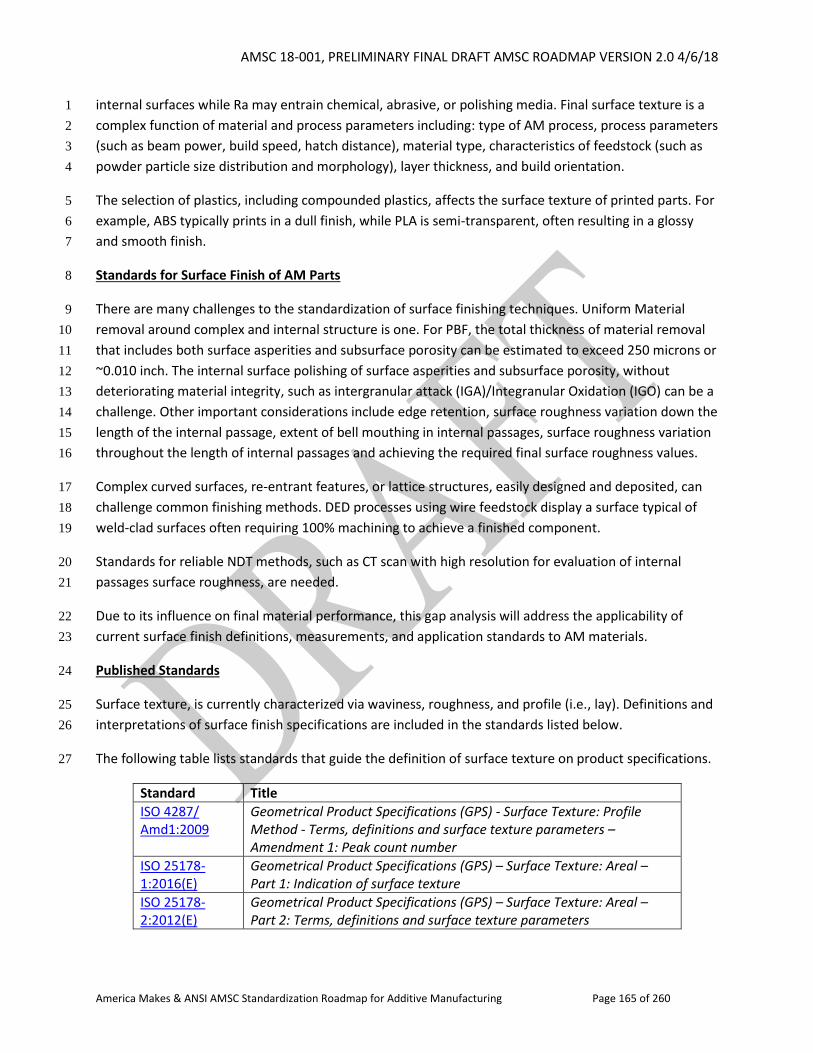
AMSC 18-001, PRELIMINARY FINAL DRAFT AMSC ROADMAP VERSION 2.0 4/6/18
America Makes & ANSI AMSC Standardization Roadmap for Additive Manufacturing Page 165 of 260
internal surfaces while Ra may entrain chemical, abrasive, or polishing media. Final surface texture is a 1
complex function of material and process parameters including: type of AM process, process parameters 2
(such as beam power, build speed, hatch distance), material type, characteristics of feedstock (such as 3
powder particle size distribution and morphology), layer thickness, and build orientation. 4
The selection of plastics, including compounded plastics, affects the surface texture of printed parts. For 5
example, ABS typically prints in a dull finish, while PLA is semi-transparent, often resulting in a glossy 6
and smooth finish. 7
Standards for Surface Finish of AM Parts 8
There are many challenges to the standardization of surface finishing techniques. Uniform Material 9
removal around complex and internal structure is one. For PBF, the total thickness of material removal 10
that includes both surface asperities and subsurface porosity can be estimated to exceed 250 microns or 11
~0.010 inch. The internal surface polishing of surface asperities and subsurface porosity, without 12
deteriorating material integrity, such as intergranular attack (IGA)/Integranular Oxidation (IGO) can be a 13
challenge. Other important considerations include edge retention, surface roughness variation down the 14
length of the internal passage, extent of bell mouthing in internal passages, surface roughness variation 15
throughout the length of internal passages and achieving the required final surface roughness values. 16
Complex curved surfaces, re-entrant features, or lattice structures, easily designed and deposited, can 17
challenge common finishing methods. DED processes using wire feedstock display a surface typical of 18
weld-clad surfaces often requiring 100% machining to achieve a finished component. 19
Standards for reliable NDT methods, such as CT scan with high resolution for evaluation of internal 20
passages surface roughness, are needed. 21
Due to its influence on final material performance, this gap analysis will address the applicability of 22
current surface finish definitions, measurements, and application standards to AM materials. 23
Published Standards 24
Surface texture, is currently characterized via waviness, roughness, and profile (i.e., lay). Definitions and 25
interpretations of surface finish specifications are included in the standards listed below. 26
The following table lists standards that guide the definition of surface texture on product specifications. 27
Standard Title
ISO 4287/ Amd1:2009
Geometrical Product Specifications (GPS) - Surface Texture: Profile Method - Terms, definitions and surface texture parameters – Amendment 1: Peak count number
ISO 25178-1:2016(E)
Geometrical Product Specifications (GPS) – Surface Texture: Areal – Part 1: Indication of surface texture
ISO 25178-2:2012(E)
Geometrical Product Specifications (GPS) – Surface Texture: Areal – Part 2: Terms, definitions and surface texture parameters
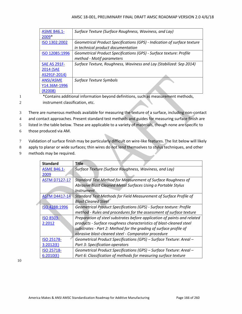
AMSC 18-001, PRELIMINARY FINAL DRAFT AMSC ROADMAP VERSION 2.0 4/6/18
America Makes & ANSI AMSC Standardization Roadmap for Additive Manufacturing Page 166 of 260
ASME B46.1-2009*
Surface Texture (Surface Roughness, Waviness, and Lay)
ISO 1302:2002 Geometrical Product Specifications (GPS) - Indication of surface texture in technical product documentation
ISO 12085:1996 Geometrical Product Specifications (GPS) - Surface texture: Profile method - Motif parameters
SAE AS 291F-2014 (SAE AS291F-2014)
Surface Texture, Roughness, Waviness and Lay (Stabilized: Sep 2014)
ANSI/ASME Y14.36M-1996 (R2008)
Surface Texture Symbols
*Contains additional information beyond definitions, such as measurement methods, 1
instrument classification, etc. 2
There are numerous methods available for measuring the texture of a surface, including non-contact 3
and contact approaches. Present standard test methods and guides for measuring surface finish are 4
listed in the table below. These are applicable to a variety of materials, though none are specific to 5
those produced via AM. 6
Validation of surface finish may be particularly difficult on wire-like features. The list below will likely 7
apply to planar or wide surfaces; thin wires do not lend themselves to stylus techniques, and other 8
methods may be required. 9
Standard Title
ASME B46.1-2009
Surface Texture (Surface Roughness, Waviness, and Lay)
ASTM D7127-17 Standard Test Method for Measurement of Surface Roughness of Abrasive Blast Cleaned Metal Surfaces Using a Portable Stylus Instrument
ASTM D4417-14 Standard Test Methods for Field Measurement of Surface Profile of Blast Cleaned Steel
ISO 4288:1996 Geometrical Product Specifications (GPS) - Surface texture: Profile method - Rules and procedures for the assessment of surface texture
ISO 8503-2:2012
Preparation of steel substrates before application of paints and related products - Surface roughness characteristics of blast-cleaned steel substrates - Part 2: Method for the grading of surface profile of abrasive blast-cleaned steel - Comparator procedure
ISO 25178-3:2012(E)
Geometrical Product Specifications (GPS) – Surface Texture: Areal – Part 3: Specification operators
ISO 25718-6:2010(E)
Geometrical Product Specifications (GPS) – Surface Texture: Areal – Part 6: Classification of methods for measuring surface texture
10
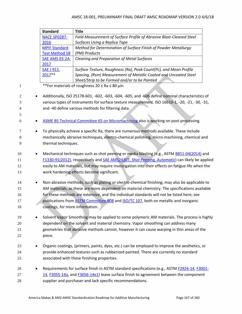
AMSC 18-001, PRELIMINARY FINAL DRAFT AMSC ROADMAP VERSION 2.0 4/6/18
America Makes & ANSI AMSC Standardization Roadmap for Additive Manufacturing Page 167 of 260
Standard Title
NACE SP0287-2016
Field Measurement of Surface Profile of Abrasive Blast-Cleaned Steel Surfaces Using a Replica Tape
MPIF Standard Test Method 58
Method for Determination of Surface Finish of Powder Metallurgy (PM) Products
SAE AMS 03-2A-2017
Cleaning and Preparation of Metal Surfaces
SAE J 911-2017**
Surface Texture, Roughness (Ra), Peak Count(Pc), and Mean Profile Spacing, (Rsm) Measurement of Metallic Coated and Uncoated Steel Sheet/Strip to be Formed and/or to be Painted
**For materials of roughness 20 ≤ Ra ≤ 80 μin 1
Additionally, ISO 25178-601, -602, -603, -604, -605, and -606 define nominal characteristics of 2
various types of instruments for surface texture measurement. ISO 16610-1, -20, -21, -30, -31, 3
and -40 define various methods for filtering data. 4
5
ASME B5 Technical Committee 65 on Micromachining also is working on post-processing. 6
To physically achieve a specific Ra, there are numerous methods available. These include 7
mechanically abrasive techniques, electro-chemical polishing, micro-machining, chemical and 8
thermal techniques. 9
Mechanical techniques such as shot peening or media blasting (e.g., ASTM B851-04(2014) and 10
F1330-91(2012), respectively and SAE AMS2430T, Shot Peening, Automatic) can likely be applied 11
easily to AM materials, but may require investigation into their effects on fatigue life when the 12
work hardening effects become significant. 13
Non-abrasive methods, such as plating or electro-chemical finishing, may also be applicable to 14
AM materials, as these are more dependent on material chemistry. The specifications available 15
for these methods are extensive, and the individual standards will not be listed here; see 16
publications from ASTM Committee B08 and ISO/TC 107, both on metallic and inorganic 17
coatings, for more information. 18
Solvent Vapor Smoothing may be applied to some polymeric AM materials. The process is highly 19
dependent on the solvent and material chemistry. Vapor smoothing can address many 20
geometries that abrasive methods cannot, however it can cause warping in thin areas of the 21
piece. 22
Organic coatings, (primers, paints, dyes, etc.) can be employed to improve the aesthetics, or 23
provide enhanced textures such as rubberized painted. There are currently no standard 24
associated with these finishing properties. 25
Requirements for surface finish in ASTM standard specifications (e.g., ASTM F2924-14, F3001-26
14, F3055-14a, and F3056-14e1) leave surface finish to agreement between the component 27
supplier and purchaser and lack specific recommendations. 28
AMSC 18-001, PRELIMINARY FINAL DRAFT AMSC ROADMAP VERSION 2.0 4/6/18
America Makes & ANSI AMSC Standardization Roadmap for Additive Manufacturing Page 168 of 260
In Development Standards: None 1
Gap P4: Surface Finish. Unique features, such as helixes, spirals, lattice structures, and internal surfaces 2
and cavities, can be manufactured using AM versus subtractive machining. However, the applicability of 3
current measurement methods to the surface of these features is not clear or captured in standards. For 4
example, features such as helixes or lattices may produce wire-like structures that are not as easily 5
measured using stylus instruments as flat surfaces. 6
Also, the suitability of current specification methods must be investigated for AM. 7
8
ANSI/ASME Y14.36M-1996 (R2008), Surface Texture Symbols may be sufficient, but further 9
investigation is required to determine if AM-specific symbols are necessary (e.g., to control stair-10
stepping or allowable surface porosity). 11
Furthermore, although there are methods available for finishing AM materials, many lack standard 12
practices. Some methods require material removal, such as micro-machining or abrasive techniques, 13
and it is not known at this time how to accommodate this in AM product specifications in a standard 14
form. Other methods require the addition of material, such as electroplating and coatings but it is 15
also unknown how to accommodate these into AM standards. 16
Lastly, as the effects of surface finish on performance become more apparent, material specification 17
recommendations must go beyond “supplier and purchaser agreement,” specifically for as-built, 18
non-machined surfaces. 19
R&D Needed: Yes 20
Standards for reliable NDT, such as XCT, for evaluation of internal passages 21
Guidance for validation of surface finish on complex features (such as wires or non-planar surfaces) 22
Investigation of mechanical techniques such as shot peening or media blasting and their effect on 23
fatigue life for AM materials 24
25
Recommendation: Verify if there are certain measurement methods more appropriate to AM-unique 26
features than a stylus approach such as Laser or White Light 3D Scanning. If so, they should be reviewed 27
for their use on AM materials and appropriate standards written. 28
The applicability of existing surface texture symbols to AM materials should be investigated. 29
Available finishing methods should be reviewed for their effects on final material properties, and 30
improved with standardized practices or guidelines where none exist. 31
Priority: Medium 32
Status of Progress: Green for R&D (metals). Unknown for Standards (metals and polymers). 33
AMSC 18-001, PRELIMINARY FINAL DRAFT AMSC ROADMAP VERSION 2.0 4/6/18
America Makes & ANSI AMSC Standardization Roadmap for Additive Manufacturing Page 169 of 260
Update: In terms of R&D for metals, NIST is currently investigating several research topics related to 1
surface texture of parts produced via laser powder bed fusion. Current research is focused on process-2
structure relationships and the identification of complex structures that result from the AM process in 3
anticipation that better identification and definition of as-built surfaces will lead to stronger functional 4
correlations for AM parts. To this end, current topic areas include: Investigation of surface texture 5
parameters beyond Ra (including both areal and profile parameters) to better define AM parts, 6
variability of as-built surface texture (i.e., methods for describing changes in the as-built surface texture 7
as position and orientation within the build chamber change), and use of XCT for determining surface 8
texture. 9
Organization: ISO/ASTM; ASME (B46 new project team 53 on surface finish), IEEE-ISTO PWG, NIST 10
2.2.3.5 Machining (metals, polymers) 11
The specifications and standards for machining of AM parts are comparable to those for machining 12
other semi-finished parts such as castings. This being the case, existing standards are adequate for 13
machining AM parts. As new “designed for AM” parts become a reality, standards may require 14
modification or new ones may have to be written. No gaps have been identified at this time. 15
2.2.3.6 Post-curing Methods (polymers) 16
Some AM processes produce cured polymers that require a secondary post-cure operation to further 17
advance crosslinking and reduce outgassing. The increased crosslinking from post-curing can result in 18
improved properties of polymer parts. These include increased stiffness, better chemical resistance, 19
higher temperature stability, reduced toxicity (due to reduction of unreacted constituents), or increased 20
strength. The reduced outgassing of the polymer parts influences their dielectric properties (e.g., 21
relative permittivity and loss factor) by directly influencing plastic density, ion viscosity, or increasing 22
dipole relaxation. 23
Unlike the many traditional polymer processing methods AM cures the deposited plastics selectively 24
layer by layer using various methods such as heated jets, binders, focused ultraviolet radiation, or laser 25
heating. In these processes the polymerization reaction can be incomplete affecting the final part 26
performance (i.e., degradation or warpage), especially if these materials are exposed to sunlight or 27
other radiation sources during use or storage. 28
In addition, an evaluation of the toxicity resulting from uncured reagents in liquid resins used during 29
processes such as Vat Photopolymerization (e.g., SLA) would also be warranted to ensure product and 30
environmental safety during and after production. 31
Ultimately, these unique risks warrant special post-cure considerations for polymers produced using 32
AM. 33
The methods 34
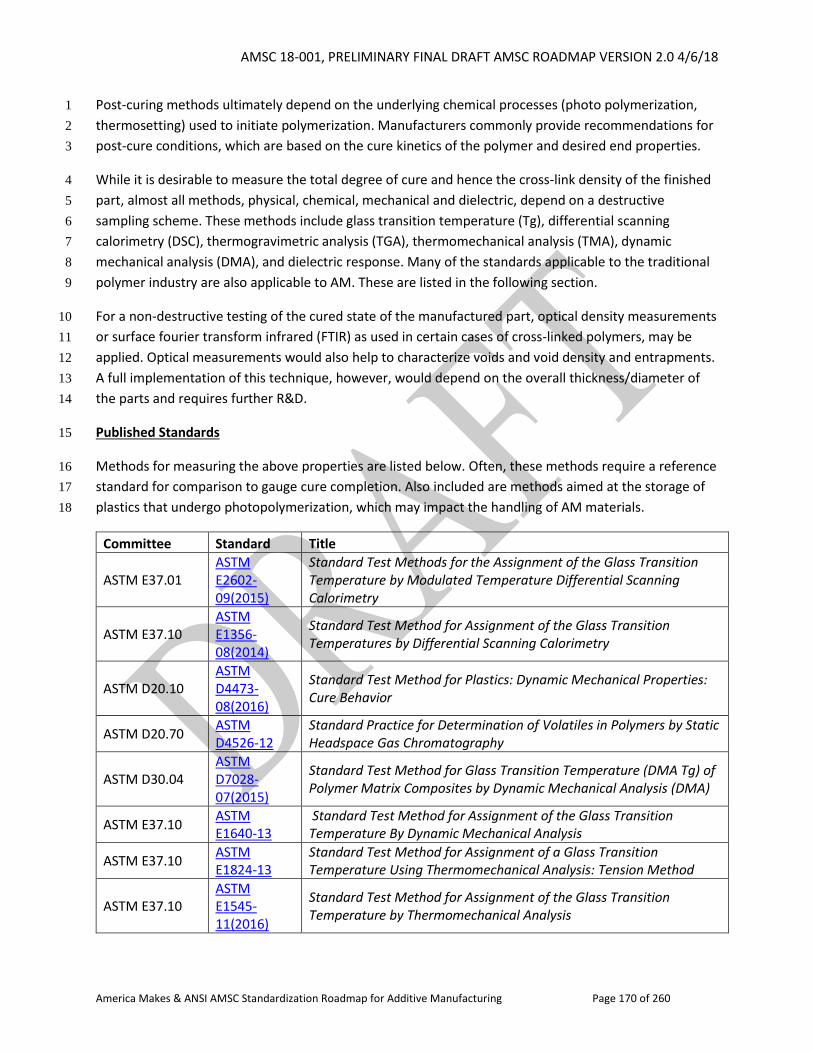
AMSC 18-001, PRELIMINARY FINAL DRAFT AMSC ROADMAP VERSION 2.0 4/6/18
America Makes & ANSI AMSC Standardization Roadmap for Additive Manufacturing Page 170 of 260
Post-curing methods ultimately depend on the underlying chemical processes (photo polymerization, 1
thermosetting) used to initiate polymerization. Manufacturers commonly provide recommendations for 2
post-cure conditions, which are based on the cure kinetics of the polymer and desired end properties. 3
While it is desirable to measure the total degree of cure and hence the cross-link density of the finished 4
part, almost all methods, physical, chemical, mechanical and dielectric, depend on a destructive 5
sampling scheme. These methods include glass transition temperature (Tg), differential scanning 6
calorimetry (DSC), thermogravimetric analysis (TGA), thermomechanical analysis (TMA), dynamic 7
mechanical analysis (DMA), and dielectric response. Many of the standards applicable to the traditional 8
polymer industry are also applicable to AM. These are listed in the following section. 9
For a non-destructive testing of the cured state of the manufactured part, optical density measurements 10
or surface fourier transform infrared (FTIR) as used in certain cases of cross-linked polymers, may be 11
applied. Optical measurements would also help to characterize voids and void density and entrapments. 12
A full implementation of this technique, however, would depend on the overall thickness/diameter of 13
the parts and requires further R&D. 14
Published Standards 15
Methods for measuring the above properties are listed below. Often, these methods require a reference 16
standard for comparison to gauge cure completion. Also included are methods aimed at the storage of 17
plastics that undergo photopolymerization, which may impact the handling of AM materials. 18
Committee Standard Title
ASTM E37.01 ASTM E2602-09(2015)
Standard Test Methods for the Assignment of the Glass Transition Temperature by Modulated Temperature Differential Scanning Calorimetry
ASTM E37.10 ASTM E1356-08(2014)
Standard Test Method for Assignment of the Glass Transition Temperatures by Differential Scanning Calorimetry
ASTM D20.10 ASTM D4473-08(2016)
Standard Test Method for Plastics: Dynamic Mechanical Properties: Cure Behavior
ASTM D20.70 ASTM D4526-12
Standard Practice for Determination of Volatiles in Polymers by Static Headspace Gas Chromatography
ASTM D30.04 ASTM D7028-07(2015)
Standard Test Method for Glass Transition Temperature (DMA Tg) of Polymer Matrix Composites by Dynamic Mechanical Analysis (DMA)
ASTM E37.10 ASTM E1640-13
Standard Test Method for Assignment of the Glass Transition Temperature By Dynamic Mechanical Analysis
ASTM E37.10 ASTM E1824-13
Standard Test Method for Assignment of a Glass Transition Temperature Using Thermomechanical Analysis: Tension Method
ASTM E37.10 ASTM E1545-11(2016)
Standard Test Method for Assignment of the Glass Transition Temperature by Thermomechanical Analysis
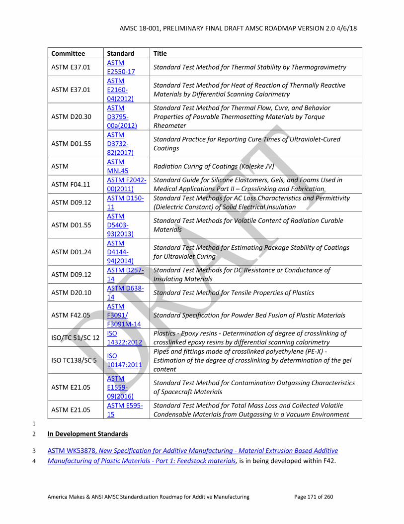
AMSC 18-001, PRELIMINARY FINAL DRAFT AMSC ROADMAP VERSION 2.0 4/6/18
America Makes & ANSI AMSC Standardization Roadmap for Additive Manufacturing Page 171 of 260
Committee Standard Title
ASTM E37.01 ASTM E2550-17
Standard Test Method for Thermal Stability by Thermogravimetry
ASTM E37.01 ASTM E2160-04(2012)
Standard Test Method for Heat of Reaction of Thermally Reactive Materials by Differential Scanning Calorimetry
ASTM D20.30 ASTM D3795-00a(2012)
Standard Test Method for Thermal Flow, Cure, and Behavior Properties of Pourable Thermosetting Materials by Torque Rheometer
ASTM D01.55 ASTM D3732-82(2017)
Standard Practice for Reporting Cure Times of Ultraviolet-Cured Coatings
ASTM ASTM MNL45
Radiation Curing of Coatings (Koleske JV)
ASTM F04.11 ASTM F2042-00(2011)
Standard Guide for Silicone Elastomers, Gels, and Foams Used in Medical Applications Part II – Crosslinking and Fabrication
ASTM D09.12 ASTM D150-11
Standard Test Methods for AC Loss Characteristics and Permittivity (Dielectric Constant) of Solid Electrical Insulation
ASTM D01.55 ASTM D5403-93(2013)
Standard Test Methods for Volatile Content of Radiation Curable Materials
ASTM D01.24 ASTM D4144-94(2014)
Standard Test Method for Estimating Package Stability of Coatings for Ultraviolet Curing
ASTM D09.12 ASTM D257-14
Standard Test Methods for DC Resistance or Conductance of Insulating Materials
ASTM D20.10 ASTM D638-14
Standard Test Method for Tensile Properties of Plastics
ASTM F42.05 ASTM F3091/ F3091M-14
Standard Specification for Powder Bed Fusion of Plastic Materials
ISO/TC 51/SC 12 ISO 14322:2012
Plastics - Epoxy resins - Determination of degree of crosslinking of crosslinked epoxy resins by differential scanning calorimetry
ISO TC138/SC 5 ISO 10147:2011
Pipes and fittings made of crosslinked polyethylene (PE-X) - Estimation of the degree of crosslinking by determination of the gel content
ASTM E21.05 ASTM E1559-09(2016)
Standard Test Method for Contamination Outgassing Characteristics of Spacecraft Materials
ASTM E21.05 ASTM E595-15
Standard Test Method for Total Mass Loss and Collected Volatile Condensable Materials from Outgassing in a Vacuum Environment
1
In Development Standards 2
ASTM WK53878, New Specification for Additive Manufacturing - Material Extrusion Based Additive 3
Manufacturing of Plastic Materials - Part 1: Feedstock materials, is in being developed within F42. 4
AMSC 18-001, PRELIMINARY FINAL DRAFT AMSC ROADMAP VERSION 2.0 4/6/18
America Makes & ANSI AMSC Standardization Roadmap for Additive Manufacturing Page 172 of 260
Gap P5: Use of Post-cure to Reduce Toxic Gases from Uncured Polymer Feedstock. An evaluation of the 1
toxic gases resulting from uncured reagents in liquid resins used during processes such as Vat 2
Photopolymerization (e.g., SLA) would be warranted to ensure product and environmental safety during 3
and after production. 4
R&D Needed: No 5
Recommendation: Augment existing standards with AM-specific recommendations for processes that 6
utilize liquid resins. Evolved gas analysis, an analytical method by which the amount and characteristics 7
of the volatile products released by an AM built- part under controlled temperature variation, is 8
recommended for finished product safety and toxicity. To analyze evolved gas quantitatively, 9
parameters such as sample chamber volume, thermal/vacuum conditions for releasing/analyzing the 10
volatiles and the techniques for the analysis need to be specified. 11
Priority: Low 12
Status of Progress: Not Started, or Unknown 13
Update: None available 14
Organization: ASTM D20, ISO/TC 261/ASTM F42 15
16
Gap P6: Guidelines for Post-curing AM Plastics to Address Outgassing. Guidelines for evaluating the 17
outgassing properties and the effects of post-polymerization treatments have not been evaluated, 18
specifically for AM materials. The voids and entrapments that can form in this case warrant some 19
method of evaluating AM plastics over traditional methods. 20
R&D Needed: Yes. R&D may be needed to look at environmental conditions and health and safety 21
aspects. Offgassing data for some materials may be archived in NASA’s Materials and Processes 22
Technical Information System (MAPTIS) since materials must undergo offgassing/toxicity testing to be 23
certified for use in crewed environments. 24
Recommendation: Extend existing methods with AM-specific recommendations. 25
Priority: Low 26
Status of Progress: Not Started, or Unknown 27
Update: None available 28
Organization: ASTM E21.05, ASTM D20, ISO/TC 138, ISO/TC 261/ASTM F42 29
AMSC 18-001, PRELIMINARY FINAL DRAFT AMSC ROADMAP VERSION 2.0 4/6/18
America Makes & ANSI AMSC Standardization Roadmap for Additive Manufacturing Page 173 of 260
2.2.4 Finished Material Properties 1
2
2.2.4.1 Introduction 3
4
Finished materials properties characterization for AM parts is necessary in order to meet the required 5
performance. This final characterization stage is focused on the result of significant due diligence 6
employed in every aspect of the AM process chain (i.e., precursor material, process control, post-7
processing). As such, establishing standards to quantify the final products’ properties/performance is 8
crucial for the wider implementation of AM technology. The expected deployment of AM to produce 9
low volumes of complex products emphasizes the need for standards that are less dependent on large-10
scale testing, the assumptions of homogenous location-specific properties, or isotropic material 11
behavior. Rather, embracing the inherent heterogeneities in AM and developing standards that can 12
quantify various properties and such heterogeneities before and after post-processing is key and 13
enables wider utilization of the unique characteristics of AM parts/components. Towards this goal, the 14
discussion in this section identifies various areas that can be used to define the characteristics of 15
finished AM parts/components and hence provide recommendations for future standards development 16
through a gap analysis. The following topics are addressed: material properties (mechanical and 17
thermal), component testing, biocompatibility and cleanliness of medical devices, chemistry, design 18
allowables, and microstructure. 19
2.2.4.2 Material Properties 20
Introduction 21
Mechanical properties include: yield strength, ultimate tensile strength, reduction in area, elongation, 22
Young’s modulus, compression strength, shear strength, bearing strength, fracture toughness, fatigue 23
strength, fatigue crack growth rate, creep strength, and many others. Depending on the application, the 24
load bearing capabilities of a part/component must meet certain mechanical properties limits. Most 25
commercial forms of wrought metal products and composites are manufactured to specifications that 26
require minimum mechanical properties, while most plastics have typical mechanical properties 27
reported by their manufacturers. Because properties of plastics are not guaranteed, typical design 28
practice uses a larger safety factor for plastic parts than for metal. Therefore, for AM parts it would be 29
ideal to have standards with guaranteed mechanical properties rather than with typical properties. 30
However, determining guaranteed properties usually requires an assumption of uniform chemistry and 31
uniformity of bulk material structure, and the variation in the structure and defects (percentage, 32
distribution, and morphology) in AM metal deposits defies the typical conceptualization of bulk material. 33
The material chemistry and AM processing conditions (including post-processing) drives the structure 34
and defect levels, and the structure and defect levels drive the properties. The processing conditions of 35
each individual build can be unique, based on variations associated with feedstock, AM system design, 36
AM system software, AM system parameter settings, and the individual parts’ build geometries. In many 37
instances, adequate access to the details of these processing conditions is not available. A thorough, 38
industry-wide understanding of the processing conditions and resulting materials is difficult to achieve 39
AMSC 18-001, PRELIMINARY FINAL DRAFT AMSC ROADMAP VERSION 2.0 4/6/18
America Makes & ANSI AMSC Standardization Roadmap for Additive Manufacturing Page 174 of 260
but is needed. Because of this, performing enough testing of the finished materials so that proper 1
statistics can be applied to the test data to ensure a low probability of the actual material properties 2
being less than those guaranteed in a specification is extremely difficult, and in some cases may be 3
unachievable. In some cases, the ability for a given AM material to achieve minimum mechanical 4
properties may need to be demonstrated for each unique AM system/AM build geometry combination. 5
More information can be obtained in the section on design allowables below. 6
Mechanical properties such as fracture toughness, fatigue strength, and fatigue crack growth are 7
typically not listed as guaranteed minimums in specifications, even those for metals. Instead, typical 8
data are determined and it is the responsibility of the design engineer to add the appropriate safety 9
factors to ensure that the part will have a low probability of failure in service. The more typical data that 10
exists, the more accurate will be the determined probability of failure of the part, so that, in general, the 11
more testing that is done, the better. 12
Thermal properties, such as thermal conductivity and specific heat capacity, of additively manufactured 13
materials are often required for thermal applications. Reliable thermal properties should be available to 14
the end user to allow for an accurate assessment of the thermal conductivity and specific heat capacity 15
of the material after manufacturing. Data are generally available on the powder thermal properties, but 16
limited data are available on the anisotropic nature of thermal properties. 17
Minimum Mechanical Properties or Test Methods for Mechanical Properties of AM Parts 18
Defining a set of minimum properties for AM products is difficult because properties are dependent on 19
the process, the process parameters, the direction of the test sample relative to the build direction, the 20
location on the build plate, the type of machine used for the build, and the geometry, among other 21
factors. Since the relationship between these variables and properties is not currently well known, and 22
since the method of qualifying minimum properties may be application dependent, developing a well-23
supported set of minimum properties is a challenge. Currently, the only standards that contain 24
minimum properties for AM parts are those from ASTM Committee F42 for specific metals produced by 25
laser powder bed fusion. These do so by leaving the method of qualification up to an agreement 26
between the purchaser and the supplier. Many other factors, not all of which are currently known or 27
understood, can interact in a way that creates highly complex processing conditions. To get test data 28
that are valid for a given process, all process parameters must be fixed under controlled conditions, 29
including post-build treatments. The resultant data are then only useful for that specific process. 30
Standardizing an optimized process therefore significantly lowers the amount of testing required to 31
determine guaranteed mechanical properties, but this standardization is likely to be machine-specific, at 32
least in the near future. See the section below on design allowables. 33
There are currently no standards on mechanical property test methods that are specific for AM parts; 34
the existing mechanical test methods for traditionally-manufactured parts are used as needed instead, 35
and are acceptable for many purposes. Unique tests that take into consideration characteristics that are 36
unique to AM parts such as property inhomogeneity and anisotropy do not currently exist. 37
Published Standards 38
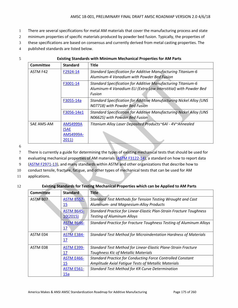
AMSC 18-001, PRELIMINARY FINAL DRAFT AMSC ROADMAP VERSION 2.0 4/6/18
America Makes & ANSI AMSC Standardization Roadmap for Additive Manufacturing Page 175 of 260
There are several specifications for metal AM materials that cover the manufacturing process and state 1
minimum properties of specific materials produced by powder bed fusion. Typically, the properties of 2
these specifications are based on consensus and currently derived from metal casting properties. The 3
published standards are listed below. 4
Existing Standards with Minimum Mechanical Properties for AM Parts 5
Committee Standard Title
ASTM F42 F2924-14 Standard Specification for Additive Manufacturing Titanium-6 Aluminum-4 Vanadium with Powder Bed Fusion
F3001-14 Standard Specification for Additive Manufacturing Titanium-6 Aluminum-4 Vanadium ELI (Extra Low Interstitial) with Powder Bed Fusion
F3055-14a Standard Specification for Additive Manufacturing Nickel Alloy (UNS N07718) with Powder Bed Fusion
F3056-14e1 Standard Specification for Additive Manufacturing Nickel Alloy (UNS N06625) with Powder Bed Fusion
SAE AMS-AM AMS4999A (SAE AMS4999A-2011)
Titanium Alloy Laser Deposited Products~6Al - 4V~Annealed
6
There is currently a guide for determining the types of existing mechanical tests that should be used for 7
evaluating mechanical properties of AM materials (ASTM F3122-14), a standard on how to report data 8
(ASTM F2971-13), and many standards within ASTM and other organizations that describe how to 9
conduct tensile, fracture, fatigue, and other types of mechanical tests that can be used for AM 10
applications. 11
Existing Standards for Testing Mechanical Properties which can be Applied to AM Parts 12
Committee Standard Title
ASTM B07 ASTM B557-15
Standard Test Methods for Tension Testing Wrought and Cast Aluminum- and Magnesium-Alloy Products
ASTM B645-10(2015)
Standard Practice for Linear-Elastic Plan-Strain Fracture Toughness Testing of Aluminum Alloys
ASTM B646-17
Standard Practice for Fracture Toughness Testing of Aluminum Alloys
ASTM E04 ASTM E384-17
Standard Test Method for Microindentation Hardness of Materials
ASTM E08
ASTM E399-17
Standard Test Method for Linear-Elastic Plane-Strain Fracture Toughness KIc of Metallic Materials
ASTM E466-15
Standard Practice for Conducting Force Controlled Constant Amplitude Axial Fatigue Tests of Metallic Materials
ASTM E561-15a
Standard Test Method for KR Curve Determination
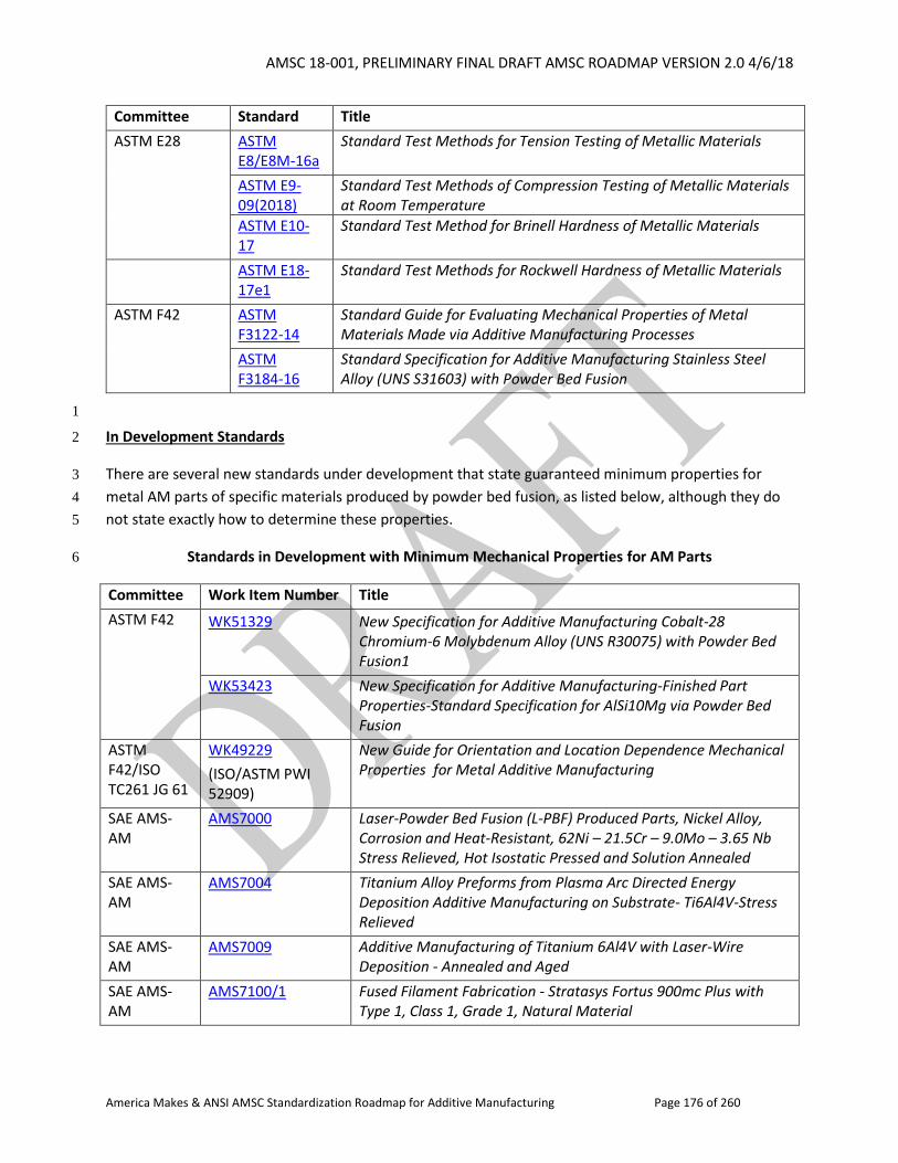
AMSC 18-001, PRELIMINARY FINAL DRAFT AMSC ROADMAP VERSION 2.0 4/6/18
America Makes & ANSI AMSC Standardization Roadmap for Additive Manufacturing Page 176 of 260
Committee Standard Title
ASTM E28 ASTM E8/E8M-16a
Standard Test Methods for Tension Testing of Metallic Materials
ASTM E9-09(2018)
Standard Test Methods of Compression Testing of Metallic Materials at Room Temperature
ASTM E10-17
Standard Test Method for Brinell Hardness of Metallic Materials
ASTM E18-17e1
Standard Test Methods for Rockwell Hardness of Metallic Materials
ASTM F42
ASTM F3122-14
Standard Guide for Evaluating Mechanical Properties of Metal Materials Made via Additive Manufacturing Processes
ASTM F3184-16
Standard Specification for Additive Manufacturing Stainless Steel Alloy (UNS S31603) with Powder Bed Fusion
1
In Development Standards 2
There are several new standards under development that state guaranteed minimum properties for 3
metal AM parts of specific materials produced by powder bed fusion, as listed below, although they do 4
not state exactly how to determine these properties. 5
Standards in Development with Minimum Mechanical Properties for AM Parts 6
Committee Work Item Number Title
ASTM F42 WK51329 New Specification for Additive Manufacturing Cobalt-28
Chromium-6 Molybdenum Alloy (UNS R30075) with Powder Bed Fusion1
WK53423 New Specification for Additive Manufacturing-Finished Part Properties-Standard Specification for AlSi10Mg via Powder Bed Fusion
ASTM F42/ISO TC261 JG 61
WK49229
(ISO/ASTM PWI 52909)
New Guide for Orientation and Location Dependence Mechanical Properties for Metal Additive Manufacturing
SAE AMS-AM
AMS7000 Laser-Powder Bed Fusion (L-PBF) Produced Parts, Nickel Alloy, Corrosion and Heat-Resistant, 62Ni – 21.5Cr – 9.0Mo – 3.65 Nb Stress Relieved, Hot Isostatic Pressed and Solution Annealed
SAE AMS-AM
AMS7004 Titanium Alloy Preforms from Plasma Arc Directed Energy Deposition Additive Manufacturing on Substrate- Ti6Al4V-Stress Relieved
SAE AMS-AM
AMS7009 Additive Manufacturing of Titanium 6Al4V with Laser-Wire Deposition - Annealed and Aged
SAE AMS-AM
AMS7100/1 Fused Filament Fabrication - Stratasys Fortus 900mc Plus with Type 1, Class 1, Grade 1, Natural Material
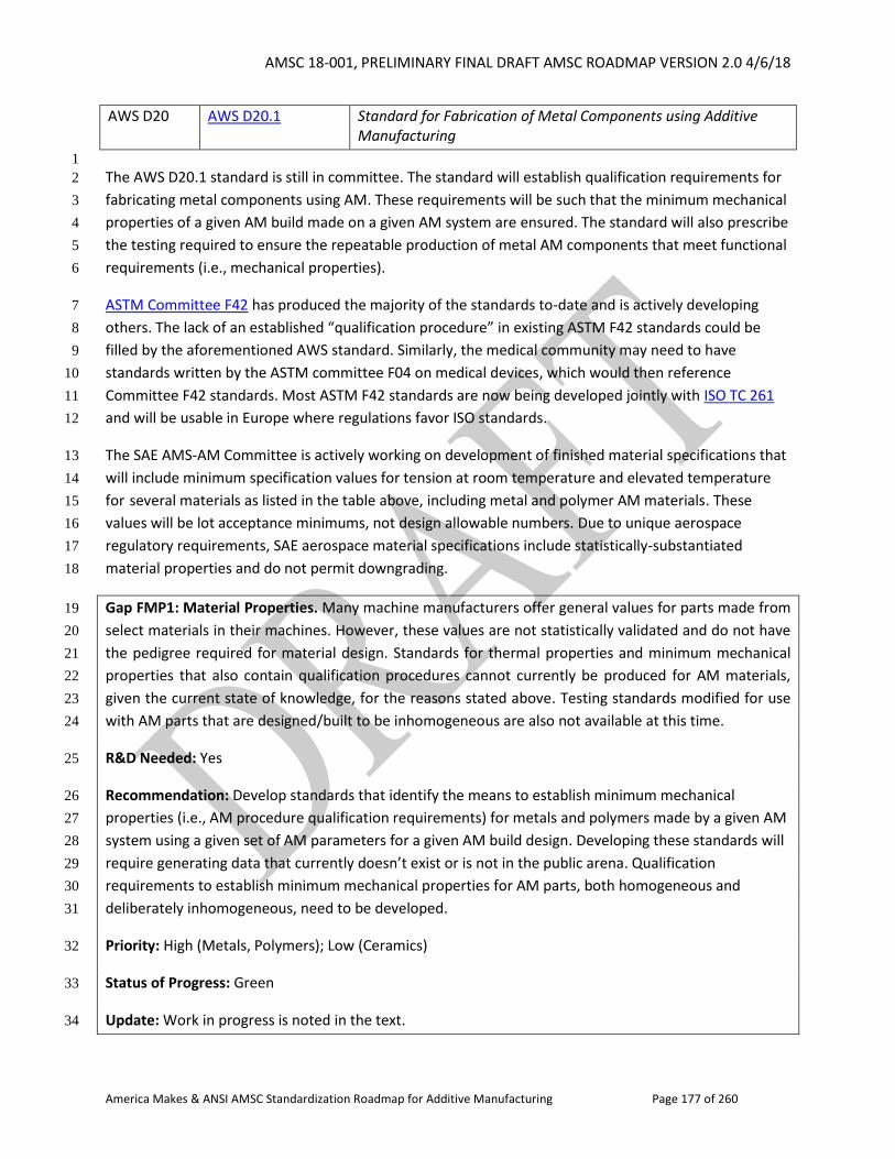
AMSC 18-001, PRELIMINARY FINAL DRAFT AMSC ROADMAP VERSION 2.0 4/6/18
America Makes & ANSI AMSC Standardization Roadmap for Additive Manufacturing Page 177 of 260
AWS D20 AWS D20.1 Standard for Fabrication of Metal Components using Additive Manufacturing
1
The AWS D20.1 standard is still in committee. The standard will establish qualification requirements for 2
fabricating metal components using AM. These requirements will be such that the minimum mechanical 3
properties of a given AM build made on a given AM system are ensured. The standard will also prescribe 4
the testing required to ensure the repeatable production of metal AM components that meet functional 5
requirements (i.e., mechanical properties). 6
ASTM Committee F42 has produced the majority of the standards to-date and is actively developing 7
others. The lack of an established “qualification procedure” in existing ASTM F42 standards could be 8
filled by the aforementioned AWS standard. Similarly, the medical community may need to have 9
standards written by the ASTM committee F04 on medical devices, which would then reference 10
Committee F42 standards. Most ASTM F42 standards are now being developed jointly with ISO TC 261 11
and will be usable in Europe where regulations favor ISO standards. 12
The SAE AMS-AM Committee is actively working on development of finished material specifications that 13
will include minimum specification values for tension at room temperature and elevated temperature 14
for several materials as listed in the table above, including metal and polymer AM materials. These 15
values will be lot acceptance minimums, not design allowable numbers. Due to unique aerospace 16
regulatory requirements, SAE aerospace material specifications include statistically-substantiated 17
material properties and do not permit downgrading. 18
Gap FMP1: Material Properties. Many machine manufacturers offer general values for parts made from 19
select materials in their machines. However, these values are not statistically validated and do not have 20
the pedigree required for material design. Standards for thermal properties and minimum mechanical 21
properties that also contain qualification procedures cannot currently be produced for AM materials, 22
given the current state of knowledge, for the reasons stated above. Testing standards modified for use 23
with AM parts that are designed/built to be inhomogeneous are also not available at this time. 24
R&D Needed: Yes 25
Recommendation: Develop standards that identify the means to establish minimum mechanical 26
properties (i.e., AM procedure qualification requirements) for metals and polymers made by a given AM 27
system using a given set of AM parameters for a given AM build design. Developing these standards will 28
require generating data that currently doesn’t exist or is not in the public arena. Qualification 29
requirements to establish minimum mechanical properties for AM parts, both homogeneous and 30
deliberately inhomogeneous, need to be developed. 31
Priority: High (Metals, Polymers); Low (Ceramics) 32
Status of Progress: Green 33
Update: Work in progress is noted in the text. 34
AMSC 18-001, PRELIMINARY FINAL DRAFT AMSC ROADMAP VERSION 2.0 4/6/18
America Makes & ANSI AMSC Standardization Roadmap for Additive Manufacturing Page 178 of 260
Organization: ASTM F42/ISO TC 261, SAE AMS-AM, AWS D20, CMH-17, MMPDS, NIST 1
2.2.4.3 Component Testing 2
Additive Part Qualification: Aerospace Perspective 3
Once form and fit have been established, the end user of an AM component must validate the 4
systematic functionality of the AM component. In addition to basic, foundational knowledge about 5
fundamental material properties and production processing effects, reasonable component level 6
destructive tests and nondestructive testing methods should be used to qualify the AM component 7
function. 8
Examples of component-level destructive tests could include: part cut-ups to validate dimensional and 9
critical material morphology, static or fatigue / damage tolerance strength evaluations from a 10
configured part, lug or crippling strength/stability evaluations, etc. Non-destructive examples could 11
include X-ray/computed tomography, pressure, eddy current, etc. 12
Note that these non-destructive functionality tests may evolve into a statistically-based plan for ongoing 13
validation of AM part quality in production. 14
Additive Part Qualification: Medical Device Perspective 15
Mechanical properties testing for components and coupons is integral to the qualification and approval 16
process. For any given part, different aspects may be critical to its function. In the medical field, AM 17
devices can be used to match a patient’s anatomy or create an implant that would otherwise be 18
impossible to manufacture. Some applications require long fatigue life and strength as the primary 19
mechanical properties (e.g., a hip implant). Others require flexibility, and the ability to degrade over 20
time in a way that maintains geometric stability (e.g., a tracheal splint). 21
In medicine, the diversity of applications and complexity of geometric shapes means there are many 22
different aspects that may be tested for any given part. It is often difficult to determine what can be 23
tested with coupons and what must be tested on the part. In addition, the quality of the part can be 24
strongly influenced by the other parts in the build volume or positioning of parts in the space, meaning 25
that careful coupon planning is imperative. Clear guidelines are not yet available for these aspects of 26
coupon use in AM for the medical field; however, some general guidelines do exist. 27
Published Standards 28
Guidelines for validation methods for manufacturing methods are available from the FDA through the 29
Quality System regulations and current Good Manufacturing Practices documentation. Other industries 30
have similar practices. These sets of documents provide a framework to help manufacturers establish 31
internal methods for verifying a production process, determining the appropriate quality controls, and 32
validating it to reduce testing burden over time. 33
AMSC 18-001, PRELIMINARY FINAL DRAFT AMSC ROADMAP VERSION 2.0 4/6/18
America Makes & ANSI AMSC Standardization Roadmap for Additive Manufacturing Page 179 of 260
In terms of published standards, the requirements for testing and validation are described in FDA's 1
Design Control Guidance for Medical Device Manufacturers (relates to FDA 21 CFR 820.30 and Sub-2
clause 4.4 of ISO 9001) and also in ISO 13485. Other published standards include ASTM F3127-16, 3
Standard Guide for Validating Cleaning Processes Used During the Manufacture of Medical Devices. 4
2.2.4.4 Biocompatibility & Cleanliness of Medical Devices 5
Biocompatibility 6
It is generally thought that biocompatibility standards such as ANSI/AAMI/ISO 10993-1:2009 have 7
already been developed to address a broad range of materials and therefore should still be sufficient to 8
assess the biocompatibility of AM materials. Biocompatibility is done on a final, finished, sterilized 9
device. 10
Published standards and guidance include: 11
ANSI/AAMI/ISO 10993-1:2009 (R2013), Biological evaluation of medical devices - Part 1: 12
Evaluation and testing within a risk management process 13
Use of International Standard ISO 10933-1, "Biological evaluation of medical devices – Part 1: 14
Evaluation and testing within a risk management process," Guidance for Industry and Food and 15
Drug Administration Staff (June 16, 2016) 16
No gaps have been identified with respect to biocompatibility. 17
18
Cleanliness of Medical AM Parts 19
It can be very difficult to clean parts of remaining raw material. Cleaning protocols can vary significantly 20
between AM technologies and between manufacturers because of the wide range of materials and 21
applications combinations that are possible. Several nondestructive measurement techniques such as 22
computed tomography (CT) or ultrasound scans are already being adopted by part producers. A 23
potentially small number of measurement and evaluation techniques could likely assess a large 24
proportion of AM parts. 25
Published standards include: 26
ASTM F3127-16, Standard Guide for Validating Cleaning Processes Used During the Manufacture 27
of Medical Devices 28
ISO 19227:2018, Implants for surgery - Cleanliness of orthopedic implants- General requirements 29
ISO/TS 19930:2017, Guidance on aspects of a risk-based approach to assuring sterility of 30
terminally sterilized, single-use health care product that is unable to withstand processing to 31
achieve maximally a sterility assurance level of 10-6 32
ASTM F3208-17, Standard Guide for Selecting Test Soils for Validation of Cleaning Methods for 33
Reusable Medical Devices 34
AMSC 18-001, PRELIMINARY FINAL DRAFT AMSC ROADMAP VERSION 2.0 4/6/18
America Makes & ANSI AMSC Standardization Roadmap for Additive Manufacturing Page 180 of 260
Standards in development include: 1
ASTM WK53082, Characterizing the Cleaning Performance of Brushes Designed to Clean the 2
Internal Channel of a Medical Device 3
ASTM WK60265, Assessing the Removal of Additive Manufacturing Residues in Medical Devices 4
Fabricated by Powder-bed Fusion 5
United States Pharmacopeia-National Formulary (USP-NF), General Chapter 788 Revision, 6
Particulate Matter Injections 7
Gap FMP3: Cleanliness of Medical AM Parts. Like many medical devices, medical AM parts must be 8
cleaned of manufacturing residues and contact materials prior to packaging or final use. For patient-9
contacting (both direct and indirect) devices this cleaning must allow the device to pass tests for 10
biological reactivity such as cytotoxicity and inflammation as described in ISO 10993. They should also 11
ensure that sufficient amounts of nonreactive AM materials such as powder are removed before use. 12
Residues left on the parts may include but are not limited to cooling fluids or AM materials (powder or 13
uncured monomer), that may be stuck within small geometric features or lattice structures. There are 14
no standardized protocols or acceptance criteria to reproducibly measure and evaluate the cleanliness 15
of a part with relevant, risk-based acceptance criteria. 16
R&D Needed: Yes. R&D is needed to establish standards which discern clean from uncleaned parts; 17
specifically, to reliably distinguish unsintered, unmelted, and uncured material from the intended part. 18
Recommendation: Develop standard test methods, metrics, and acceptance criteria for measuring 19
cleanliness of complex 3D geometries that are based on existing standards but focus on AM-specific 20
considerations. ASTM F04 already has work in progress. 21
Priority: High 22
Status of Progress: Green 23
Update: As noted, ASTM F04.15 is working on WK53082 and WK60265. 24
Organization: AAMI, ASTM F04, ASTM F42/ISO TC 261, ISO, ISO/TC 150, ISO/TC 194 25
2.2.4.5 Chemistry 26
Introduction 27
Chemistry of materials (i.e., chemical composition) is the foundation that drives material performance 28
such as mechanical properties and corrosion resistance. Ensuring the proper chemical composition of 29
materials throughout the manufacturing process is essential in the certification of products used in 30
industry. It is essential for product specifications to contain rigorous chemistry requirements as well as 31
standard chemical analysis test methods to ensure that delivered product meets the intended design 32
requirements. Most additive manufacturing processes rapidly melt and solidify materials, thus having 33
the ability to lead to unusual behavior in some material systems compared to traditional manufacturing 34
AMSC 18-001, PRELIMINARY FINAL DRAFT AMSC ROADMAP VERSION 2.0 4/6/18
America Makes & ANSI AMSC Standardization Roadmap for Additive Manufacturing Page 181 of 260
methods. Some unusual behavior has been noted in changes from pre-build chemistry to post-build 1
chemistry. Therefore, it is essential for additive manufacturing standards to contain chemistry 2
requirements and standard chemical analysis test methods for both feedstock (precursor) materials and 3
as-built parts (finished materials). 4
Published Standards 5
There are several specifications for metal AM parts fabricated using powder bed fusion that have 6
requirements for chemical composition of the as-build part. Generally, these specifications require both 7
the feedstock (precursor) material and the as-built part to meet required chemical composition 8
requirements defined in the specification. 9
There are currently well-established standards for chemical analysis test methods for metal materials 10
(examples include ASTM E34, E353, etc.). 11
Existing Specifications Including Chemical Composition Requirements for AM Parts 12
Committee Standard Title
ASTM F42 F2924-14 Standard Specification for Additive Manufacturing Titanium-6 Aluminum-4 Vanadium with Powder Bed Fusion
F3001-14 Standard Specification for Additive Manufacturing Titanium-6 Aluminum-4 Vanadium ELI (Extra Low Interstitial) with Powder Bed Fusion
F3055-14a Standard Specification for Additive Manufacturing Nickel Alloy (UNS N07718) with Powder Bed Fusion
ASTM F42 F3056-14e1 Standard Specification for Additive Manufacturing Nickel Alloy (UNS N06625) with Powder Bed Fusion
F3184-16 Standard Specification for Additive Manufacturing Stainless Steel Alloy (UNS S31603) with Powder Bed Fusion
13
In Development Standards 14
Specifications in Development Including Chemical Composition Requirements for AM Parts 15
Committee Work Item Number
Title
ASTM F42 WK51329 Standard Specification for Additive Manufacturing Cobalt-28 Chromium-6 Molybdenum Alloy (UNS R30075) with Powder Bed Fusion1
WK53423 New Specification for Additive Manufacturing-Finished Part Properties-Standard Specification for AlSi10Mg via Powder Bed Fusion
AMSC 18-001, PRELIMINARY FINAL DRAFT AMSC ROADMAP VERSION 2.0 4/6/18
America Makes & ANSI AMSC Standardization Roadmap for Additive Manufacturing Page 182 of 260
SAE AMS-AM AMS7000 Laser-Powder Bed Fusion (L-PBF) Produced Parts, Nickel Alloy, Corrosion and Heat-Resistant, 62Ni – 21.5Cr – 9.0Mo – 3.65 Nb Stress Relieved, Hot Isostatic Pressed and Solution Annealed
1
While no gaps have been identified, SDOs (e.g., ASTM, SAE, etc.) should continue to include chemical 2
composition requirements in AM part (finished materials) specifications. Standards also should continue 3
to require both the feedstock (precursor) material and as-built part (finished material) to conform to 4
their specific chemistry requirements unless otherwise determined necessary. 5
2.2.4.6 Design Allowables 6
Design allowables are statistically derived material properties based on a defined set of data and 7
analysis methods. The allowables are used as design values that are accepted by government procuring 8
and/or certification agencies for the development and manufacture of aerospace products. For the 9
widespread adoption of AM for the aerospace industry, these design allowables must be developed and 10
accepted by the various procuring and certification agencies. 11
Test Methods or Best Practice Guides for Design Allowables of AM Parts 12
The development of standard test methods, specifications, and best practice guides will allow for the 13
standardization of additively manufactured materials design data that is acceptable to government 14
procuring and certification agencies. The data obtained through these standards and specifications can 15
be used for statistical analysis of design allowables (typically A-Basis or B-Basis values). Currently, there 16
is no accepted or approved statistical analysis procedure for additively manufactured materials. Once 17
these design allowables are established, the application of AM components can be accelerated. 18
The following test standards and specifications are published for use with additively manufactured 19
materials: 20
Material Type
Committee Standard Title
Any ASTM F42 ISO/ASTM 52900:2015
Additive Manufacturing - General principles – Terminology
Metal ASTM F42 F2924-14 Standard Specification for Additive Manufacturing Titanium-6 Aluminum-4 Vanadium with Powder Bed Fusion
Metal ASTM F42 F3055-14a Standard Specification for Additive Manufacturing Nickel Alloy (UNS N07718) with Powder Bed Fusion
Metal ASTM F42 F3056-14e1 Standard Specification for Additive Manufacturing Nickel Alloy (UNS N06625) with Powder Bed Fusion
Any ASTM F42 F2971-13 Standard Practice for Reporting Data for Test Specimens Prepared by Additive Manufacturing
Metal ASTM F42 F3122-14 Standard Guide for Evaluating Mechanical Properties of Metal Materials Made via Additive Manufacturing Processes
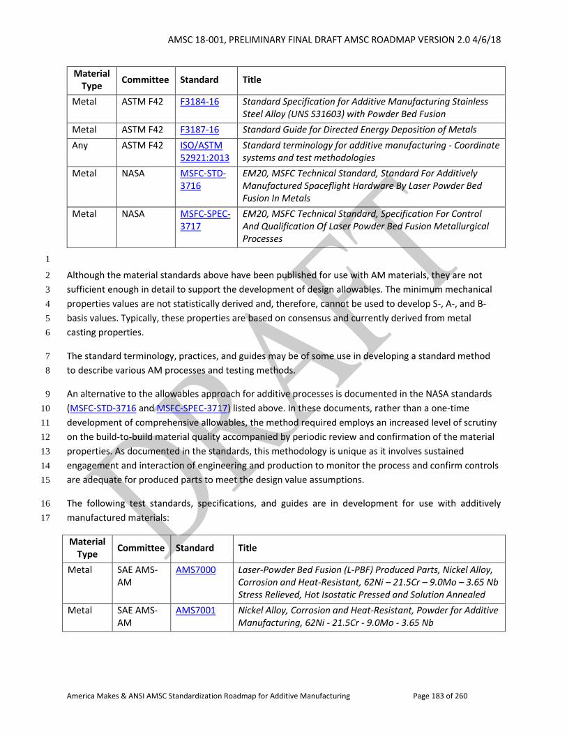
AMSC 18-001, PRELIMINARY FINAL DRAFT AMSC ROADMAP VERSION 2.0 4/6/18
America Makes & ANSI AMSC Standardization Roadmap for Additive Manufacturing Page 183 of 260
Material Type
Committee Standard Title
Metal ASTM F42 F3184-16 Standard Specification for Additive Manufacturing Stainless Steel Alloy (UNS S31603) with Powder Bed Fusion
Metal ASTM F42 F3187-16 Standard Guide for Directed Energy Deposition of Metals
Any ASTM F42 ISO/ASTM 52921:2013
Standard terminology for additive manufacturing - Coordinate systems and test methodologies
Metal NASA MSFC-STD-3716
EM20, MSFC Technical Standard, Standard For Additively Manufactured Spaceflight Hardware By Laser Powder Bed Fusion In Metals
Metal NASA MSFC-SPEC-3717
EM20, MSFC Technical Standard, Specification For Control And Qualification Of Laser Powder Bed Fusion Metallurgical Processes
1
Although the material standards above have been published for use with AM materials, they are not 2
sufficient enough in detail to support the development of design allowables. The minimum mechanical 3
properties values are not statistically derived and, therefore, cannot be used to develop S-, A-, and B-4
basis values. Typically, these properties are based on consensus and currently derived from metal 5
casting properties. 6
The standard terminology, practices, and guides may be of some use in developing a standard method 7
to describe various AM processes and testing methods. 8
An alternative to the allowables approach for additive processes is documented in the NASA standards 9
(MSFC-STD-3716 and MSFC-SPEC-3717) listed above. In these documents, rather than a one-time 10
development of comprehensive allowables, the method required employs an increased level of scrutiny 11
on the build-to-build material quality accompanied by periodic review and confirmation of the material 12
properties. As documented in the standards, this methodology is unique as it involves sustained 13
engagement and interaction of engineering and production to monitor the process and confirm controls 14
are adequate for produced parts to meet the design value assumptions. 15
The following test standards, specifications, and guides are in development for use with additively 16
manufactured materials: 17
Material Type
Committee Standard Title
Metal SAE AMS-AM
AMS7000 Laser-Powder Bed Fusion (L-PBF) Produced Parts, Nickel Alloy, Corrosion and Heat-Resistant, 62Ni – 21.5Cr – 9.0Mo – 3.65 Nb Stress Relieved, Hot Isostatic Pressed and Solution Annealed
Metal SAE AMS-AM
AMS7001 Nickel Alloy, Corrosion and Heat-Resistant, Powder for Additive Manufacturing, 62Ni - 21.5Cr - 9.0Mo - 3.65 Nb
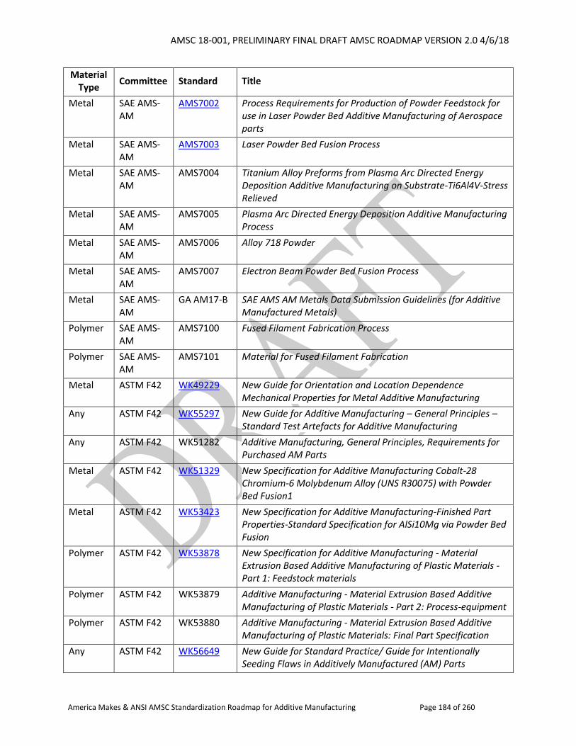
AMSC 18-001, PRELIMINARY FINAL DRAFT AMSC ROADMAP VERSION 2.0 4/6/18
America Makes & ANSI AMSC Standardization Roadmap for Additive Manufacturing Page 184 of 260
Material Type
Committee Standard Title
Metal SAE AMS-AM
AMS7002 Process Requirements for Production of Powder Feedstock for use in Laser Powder Bed Additive Manufacturing of Aerospace parts
Metal SAE AMS-AM
AMS7003 Laser Powder Bed Fusion Process
Metal SAE AMS-AM
AMS7004 Titanium Alloy Preforms from Plasma Arc Directed Energy Deposition Additive Manufacturing on Substrate-Ti6Al4V-Stress Relieved
Metal SAE AMS-AM
AMS7005 Plasma Arc Directed Energy Deposition Additive Manufacturing Process
Metal SAE AMS-AM
AMS7006 Alloy 718 Powder
Metal SAE AMS-AM
AMS7007 Electron Beam Powder Bed Fusion Process
Metal SAE AMS-AM
GA AM17-B SAE AMS AM Metals Data Submission Guidelines (for Additive Manufactured Metals)
Polymer SAE AMS-AM
AMS7100 Fused Filament Fabrication Process
Polymer SAE AMS-AM
AMS7101 Material for Fused Filament Fabrication
Metal ASTM F42 WK49229 New Guide for Orientation and Location Dependence Mechanical Properties for Metal Additive Manufacturing
Any ASTM F42 WK55297 New Guide for Additive Manufacturing – General Principles – Standard Test Artefacts for Additive Manufacturing
Any ASTM F42 WK51282 Additive Manufacturing, General Principles, Requirements for Purchased AM Parts
Metal ASTM F42 WK51329 New Specification for Additive Manufacturing Cobalt-28 Chromium-6 Molybdenum Alloy (UNS R30075) with Powder Bed Fusion1
Metal ASTM F42 WK53423 New Specification for Additive Manufacturing-Finished Part Properties-Standard Specification for AlSi10Mg via Powder Bed Fusion
Polymer ASTM F42 WK53878 New Specification for Additive Manufacturing - Material Extrusion Based Additive Manufacturing of Plastic Materials - Part 1: Feedstock materials
Polymer ASTM F42 WK53879 Additive Manufacturing - Material Extrusion Based Additive Manufacturing of Plastic Materials - Part 2: Process-equipment
Polymer ASTM F42 WK53880 Additive Manufacturing - Material Extrusion Based Additive Manufacturing of Plastic Materials: Final Part Specification
Any ASTM F42 WK56649 New Guide for Standard Practice/ Guide for Intentionally Seeding Flaws in Additively Manufactured (AM) Parts
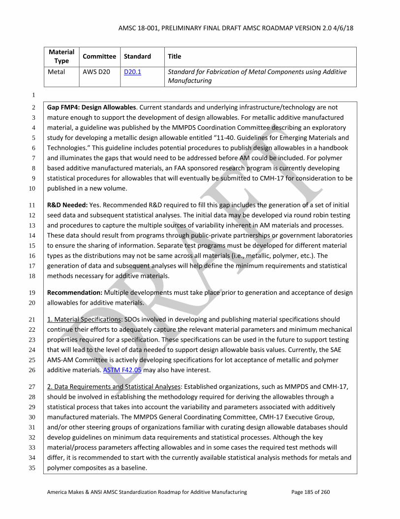
AMSC 18-001, PRELIMINARY FINAL DRAFT AMSC ROADMAP VERSION 2.0 4/6/18
America Makes & ANSI AMSC Standardization Roadmap for Additive Manufacturing Page 185 of 260
Material Type
Committee Standard Title
Metal AWS D20 D20.1 Standard for Fabrication of Metal Components using Additive Manufacturing
1
Gap FMP4: Design Allowables. Current standards and underlying infrastructure/technology are not 2
mature enough to support the development of design allowables. For metallic additive manufactured 3
material, a guideline was published by the MMPDS Coordination Committee describing an exploratory 4
study for developing a metallic design allowable entitled “11-40. Guidelines for Emerging Materials and 5
Technologies.” This guideline includes potential procedures to publish design allowables in a handbook 6
and illuminates the gaps that would need to be addressed before AM could be included. For polymer 7
based additive manufactured materials, an FAA sponsored research program is currently developing 8
statistical procedures for allowables that will eventually be submitted to CMH-17 for consideration to be 9
published in a new volume. 10
R&D Needed: Yes. Recommended R&D required to fill this gap includes the generation of a set of initial 11
seed data and subsequent statistical analyses. The initial data may be developed via round robin testing 12
and procedures to capture the multiple sources of variability inherent in AM materials and processes. 13
These data should result from programs through public-private partnerships or government laboratories 14
to ensure the sharing of information. Separate test programs must be developed for different material 15
types as the distributions may not be same across all materials (i.e., metallic, polymer, etc.). The 16
generation of data and subsequent analyses will help define the minimum requirements and statistical 17
methods necessary for additive materials. 18
Recommendation: Multiple developments must take place prior to generation and acceptance of design 19
allowables for additive materials. 20
1. Material Specifications: SDOs involved in developing and publishing material specifications should 21
continue their efforts to adequately capture the relevant material parameters and minimum mechanical 22
properties required for a specification. These specifications can be used in the future to support testing 23
that will lead to the level of data needed to support design allowable basis values. Currently, the SAE 24
AMS-AM Committee is actively developing specifications for lot acceptance of metallic and polymer 25
additive materials. ASTM F42.05 may also have interest. 26
2. Data Requirements and Statistical Analyses: Established organizations, such as MMPDS and CMH-17, 27
should be involved in establishing the methodology required for deriving the allowables through a 28
statistical process that takes into account the variability and parameters associated with additively 29
manufactured materials. The MMPDS General Coordinating Committee, CMH-17 Executive Group, 30
and/or other steering groups of organizations familiar with curating design allowable databases should 31
develop guidelines on minimum data requirements and statistical processes. Although the key 32
material/process parameters affecting allowables and in some cases the required test methods will 33
differ, it is recommended to start with the currently available statistical analysis methods for metals and 34
polymer composites as a baseline. 35
AMSC 18-001, PRELIMINARY FINAL DRAFT AMSC ROADMAP VERSION 2.0 4/6/18
America Makes & ANSI AMSC Standardization Roadmap for Additive Manufacturing Page 186 of 260
3. Test methods: Test standards organizations, such as ASTM/ISO, should provide recommendations on 1
established test methods with special considerations for AM materials. If necessary, new coupon or 2
component test methods should be developed. 3
Priority: High (Material Specifications); Medium (Data Requirements and Statistical Analyses): Medium 4
(Test Methods) 5
Status of Progress: Green 6
Update: At this time, no publicly available methodology for design allowables of additively 7
manufactured materials exist. However, the three sections listed above (Material Specifications, Data 8
Requirements and Statistical Analyses, and Test Methods) are all being addressed throughout multiple 9
SDOs and other programs. 10
Material specifications are being generated by multiple SDOs at this time. SAE has a Data Management 11
Sub-Committee currently defining guidelines to generate specifications minimum values for both metals 12
and polymers. In addition to the work in progress noted in the text and gap statement, ASME's BPVC 13
committee is looking at this. Regarding characterization methods for metals, the MMPDS coordinating 14
committee has concerns that existing data requirements and statistical analysis methods are not 15
sufficient. Their primary concern is the level of maturity of standards and specifications needed to 16
ensure consistent properties. Polymer AM material test methods have similar issues; methods can 17
either be adopted from plastic or polymer matrix composites methods, both of which may need 18
modification. 19
Organization: ASTM F42/ISO TC 261, SAE AMS-AM, AWS, NASA, ASME BPVC, MMPDS, CMH-17, NIST 20
2.2.4.7 Microstructure 21
22
Microstructure is a multiscale subsurface structure of a metallic alloy that can be viewed by either 23
surface treatments that reveal the subsurface structures (e.g., etching) or by recording the subsurface 24
response to external stimuli (e.g., electron beam, X-ray, etc.). 25
For metallic alloys, subsurface structures include phase-based features (e.g., laths, grains, etc.) and 26
defects (e.g., cracks, porosities). Both identification and quantification of various microstructure 27
features are needed to link them with the additively manufactured part’s performance. For phase-based 28
features, both morphology and crystallography of various phases need to be identified and quantified; 29
these are dependent on the alloy system and the thermomechanical pedigree. Defects morphology, 30
which is dependent on processing pedigree, also needs to be identified and quantified. Due to the 31
heterogeneous nature of the AM process, microstructure quantifications should account for the 3D 32
spatial variability of various microstructure features that often results in 3D spatial heterogeneity in 33
material properties. 34
Microstructure has a direct impact on an AM part’s performance because it affects its location specific 35
material properties under static and dynamic loading conditions. Thus, understanding the 36
AMSC 18-001, PRELIMINARY FINAL DRAFT AMSC ROADMAP VERSION 2.0 4/6/18
America Makes & ANSI AMSC Standardization Roadmap for Additive Manufacturing Page 187 of 260
microstructure characteristics (spatial variability of crystallography and morphology) leads to accurate 1
estimates of the part’s in-service performance and further optimization of post-processing heat 2
treatments to control the location of specific material properties and, hence, the part’s in-service 3
performance. 4
Test Methods or Best Practice Guides for Microstructure of AM Parts 5
The nature of vertically building parts in AM causes directionality in the thermal gradient that is 6
complicated by the variability in a part’s geometry and the resultant heterogeneous microstructure that 7
is characterized by 3D spatial variability. Thus, microstructure identification and quantification in AM 8
should consider microstructure heterogeneity as the norm and homogeneity as the special case. Fast 9
cooling rates from the melt combined with thermal gradients can result in submicron scale 10
microstructure features (e.g., martensite needles or alpha laths in alpha/beta titanium) within 11
millimeter scale features (e.g., prior beta grains in titanium alloys or large gamma grains in TiAl). Thus, 12
microstructure identification and quantification methods should account for multiscale 3D 13
microstructure spatial heterogeneities that span to tens of millimeters while having the resolution of 14
sub-micrometers. While the physics of traditional casting and welding processes are different than the 15
one associated with metallic additive manufacturing, established standards for microstructure 16
identification and quantification in both techniques can be used as a start towards standards for AM. 17
However, they often focus on the morphology of phases with limited standards for crystallography and 18
no standards for spatial distribution. 19
20
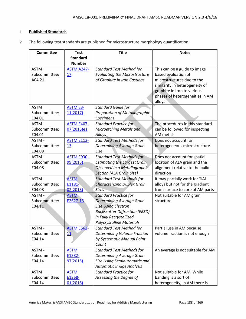
AMSC 18-001, PRELIMINARY FINAL DRAFT AMSC ROADMAP VERSION 2.0 4/6/18
America Makes & ANSI AMSC Standardization Roadmap for Additive Manufacturing Page 188 of 260
Published Standards 1
The following test standards are published for microstructure morphology quantification: 2
Committee Test Standard Number
Title Notes
ASTM Subcommittee: A04.21
ASTM A247-17
Standard Test Method for Evaluating the Microstructure of Graphite in Iron Castings
This can be a guide to image based evaluation of microstructures due to the similarity in heterogeneity of graphite in iron to various phases of heterogeneities in AM alloys
ASTM Subcommittee: E04.01
ASTM E3-11(2017)
Standard Guide for Preparation of Metallographic Specimens
ASTM Subcommittee: E04.01
ASTM E407-07(2015)e1
Standard Practice for Microetching Metals and Alloys
The procedures in this standard can be followed for inspecting AM metals
ASTM -Subcommittee: E04.08
ASTM E112-13
Standard Test Methods for Determining Average Grain Size
Does not account for heterogeneous microstructure
ASTM -Subcommittee: E04.08
ASTM E930-99(2015)
Standard Test Methods for Estimating the Largest Grain Observed in a Metallographic Section (ALA Grain Size)
Does not account for spatial location of ALA grain and the alignment relative to the build direction
ASTM -Subcommittee: E04.08
ASTM E1181-02(2015)
Standard Test Methods for Characterizing Duplex Grain Sizes
It may partially work for TiAl alloys but not for the gradient from surface to core of AM parts
ASTM -Subcommittee: E04.11
ASTM E2627-13
Standard Practice for Determining Average Grain Size Using Electron Backscatter Diffraction (EBSD) in Fully Recrystallized Polycrystalline Materials
Not suitable for AM grain structure
ASTM -Subcommittee: E04.14
ASTM E562-11
Standard Test Method for Determining Volume Fraction by Systematic Manual Point Count
Partial use in AM because volume fraction is not enough
ASTM -Subcommittee: E04.14
ASTM E1382-97(2015)
Standard Test Methods for Determining Average Grain Size Using Semiautomatic and Automatic Image Analysis
An average is not suitable for AM
ASTM Subcommittee: E04.14
ASTM E1268- 01(2016)
Standard Practice for Assessing the Degree of
Not suitable for AM. While banding is a sort of heterogeneity, in AM there is
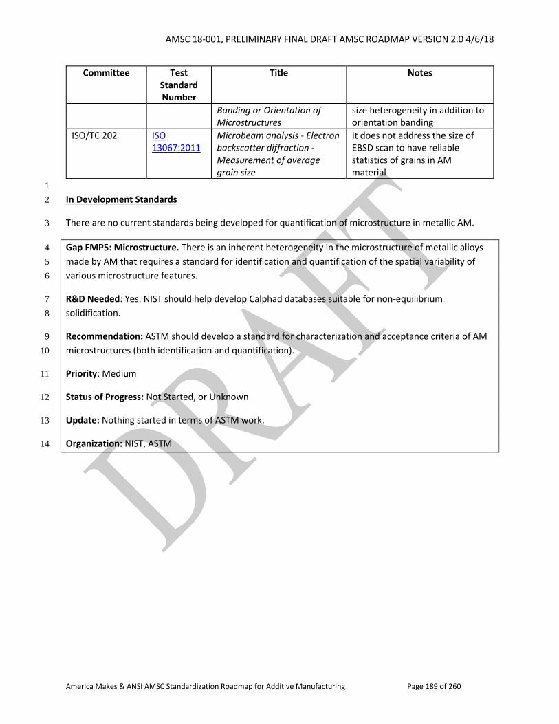
AMSC 18-001, PRELIMINARY FINAL DRAFT AMSC ROADMAP VERSION 2.0 4/6/18
America Makes & ANSI AMSC Standardization Roadmap for Additive Manufacturing Page 189 of 260
Committee Test Standard Number
Title Notes
Banding or Orientation of Microstructures
size heterogeneity in addition to orientation banding
ISO/TC 202 ISO 13067:2011
Microbeam analysis - Electron backscatter diffraction - Measurement of average grain size
It does not address the size of EBSD scan to have reliable statistics of grains in AM material
1
In Development Standards 2
There are no current standards being developed for quantification of microstructure in metallic AM. 3
Gap FMP5: Microstructure. There is an inherent heterogeneity in the microstructure of metallic alloys 4
made by AM that requires a standard for identification and quantification of the spatial variability of 5
various microstructure features. 6
R&D Needed: Yes. NIST should help develop Calphad databases suitable for non-equilibrium 7
solidification. 8
Recommendation: ASTM should develop a standard for characterization and acceptance criteria of AM 9
microstructures (both identification and quantification). 10
Priority: Medium 11
Status of Progress: Not Started, or Unknown 12
Update: Nothing started in terms of ASTM work. 13
Organization: NIST, ASTM 14

AMSC 18-001, PRELIMINARY FINAL DRAFT AMSC ROADMAP VERSION 2.0 4/6/18
America Makes & ANSI AMSC Standardization Roadmap for Additive Manufacturing Page 190 of 260
1
2
3
4
5
6
[this page intentionally left blank] 7
8
AMSC 18-001, PRELIMINARY FINAL DRAFT AMSC ROADMAP VERSION 2.0 4/6/18
America Makes & ANSI AMSC Standardization Roadmap for Additive Manufacturing Page 191 of 260
2.3 Qualification & Certification 1
2.3.1 Introduction 2
Each section in this roadmap discusses various issues and relevant standards at some point in the 3
lifecycle of an AM part. This section discusses some of these issues – and applicable qualification and 4
certification (Q&C) procedures – in more detail. Please note that some gaps related to Q&C also appear 5
elsewhere in this roadmap.13 6
Whereas AM produced components must be tested for performance much the same as traditionally 7
manufactured items, there will be aspects unique to AM that must be addressed before such 8
components are deployed. This is especially the case for mission and safety-critical components and 9
applications. A critical part may be required to be built from qualified material, using qualified 10
processes, etc. Suffice it to say that there are many types of qualifications that can be discussed within 11
the scope of AM. As such, Q&C is a major area of focus for AM.14 12
The first part of this section focuses on industry documents and related activities that provide guidance 13
on suggested or necessary components of an acceptable qualification procedure. The next part 14
discusses primary qualification issues within the aerospace, defense, and medical sectors, noting areas 15
where there is a need for further guidance on the topic of qualification. 16
Q&C Terminology 17
One of the major issues clouding the discussion of Q&C in AM is the ambiguity of terms and their usage. 18
For example, ISO 9000:2015, Quality management systems – Fundamentals and vocabulary, does not 19
define qualification or certification, but defines verification and competence and notes that qualification 20
is sometimes used as a synonym for each: 21
Verification: Confirmation, through the provision of objective evidence, that specified requirements 22
have been fulfilled 23
Note 1 to entry: The objective evidence needed for a verification can be the result of an 24
inspection or of other forms of determination such as performing alternative calculations or 25
reviewing documents. 26
Note 2 to entry: The activities carried out for verification are sometimes called a 27
qualification [emphasis added] process. 28
Note 3 to entry: The word “verified” is used to designate the corresponding status. 29
13 See Gaps D12, D20, PC4, P1, FMP1, and NDE5. 14 Prepared by Energetics Incorporated for the National Institute of Standards and Technology, Measurement Science Roadmap for Metal-Based Additive Manufacturing, May 2013, https://www.nist.gov/sites/default/files/documents/el/isd/NISTAdd_Mfg_Report_FINAL-2.pdf
AMSC 18-001, PRELIMINARY FINAL DRAFT AMSC ROADMAP VERSION 2.0 4/6/18
America Makes & ANSI AMSC Standardization Roadmap for Additive Manufacturing Page 192 of 260
1
Competence: Ability to apply knowledge and skills to achieve intended results 2
Note 1 to entry: Demonstrated competence is sometimes referred to as qualification 3
[emphasis added]. 4
Note 2 to entry: This constitutes one of the common terms and core definitions for ISO 5
management system standards given in Annex SL of the Consolidated ISO Supplement to the 6
ISO/IEC Directives, Part 1. The original definition has been modified by adding Note 1 to 7
entry. 8
9
For purposes of this roadmap, qualification is defined as ensuring suitability to meet functional 10
requirements in a repeatable manner, or assuring the desired outcome of a defined process. Such 11
validation is a shared responsibility of both the supplier and the end user. 12
Certification has a similar formal definition to verification (qualification): 13
Certification: Third-party attestation related to products, processes, or persons that conveys 14
assurance that specified requirements have been demonstrated.15 15
A formal definitional distinction therefore is that certification describes something done by an 16
authorized third party independent of the person or organization that provides the product, as well as 17
the user or customer of the product. 18
Validation is defined in ISO 9000:2015 as: confirmation, through the provision of objective evidence, 19
that the requirements for a specific intended use or application have been fulfilled. 20
Verification and validation are also defined in the International Vocabulary of Metrology – Basic and 21
General Concepts and Associated Terms (VIM), 3rd edition, 2008 version with minor corrections (JCGM 22
200:2012).16 23
Verification: provision of objective evidence that a given item fulfils specified requirements 24
25
Validation: verification, where the specified requirements are adequate for an intended use 26
Aside from ambiguities in formal definitions, there are sometimes differences in how terms are used by 27
industry sector. The aerospace industry has adopted SAE AS 9100-1999, a sector variation of ISO 9000. 28
The defense industry approach to certification of parts/criticality of parts aligns with the aerospace 29
15 The United States Conformity Assessment Principles (USCAP) www.ansi.org/uscap. Italics in the USCAP definition indicate a term has a specific meaning in the United States. The USCAP definition is based on the ISO/IEC 17000:2004 definition: Certification - Third-party attestation related to products, processes, systems or persons
NOTE 1- Certification of a management system is sometimes also called registration. NOTE 2 - Certification is applicable to all objects of conformity assessment except for conformity assessment bodies themselves, to which accreditation is applicable.
16 http://www.bipm.org/utils/common/documents/jcgm/JCGM_200_2012.pdf
AMSC 18-001, PRELIMINARY FINAL DRAFT AMSC ROADMAP VERSION 2.0 4/6/18
America Makes & ANSI AMSC Standardization Roadmap for Additive Manufacturing Page 193 of 260
industry practice except for terminology. The aerospace industry qualification procedure equates to 1
what the defense industry describes as “certification.”17 Terminology within the medical community is 2
defined in law or regulation. 3
Though not specific to Q&C aspects, AM terminology documents include: 4
ISO/ASTM 52900:2015, Additive manufacturing - General principles - Terminology 5
ISO/ASTM 52921:2013, Standard terminology for additive manufacturing - Coordinate 6
systems and test methodologies 7
ASTM E2161-15, Standard Terminology Relating to Performance Validation in Thermal Analysis and 8
Rheology, is another possible reference document. 9
In addition to the source documents already mentioned, the ISO Online Browsing Platform18 is a useful 10
resource for researching how terms are defined in various standardization contexts. 11
Gap QC1: Harmonization of AM Q&C Terminology. One of the challenges in discussing qualification and 12
certification in AM is the ambiguity of the terms qualification, certification, verification, and validation, 13
and how these terms are used by different industrial sectors when describing Q&C of materials, parts, 14
processes, personnel, and equipment. 15
R&D Needed: No 16
Recommendation: Compare how the terms qualification, certification, verification and validation are 17
used by industry sector. Update as needed existing quality management system standards and other 18
terminology standards to harmonize definitions and encourage consistent use of terms across industry 19
sectors with respect to AM. 20
Priority: High 21
Status of Progress: Green 22
Update: In discussions between the AMSC advisory group and the SDOs, there was a general sense that 23
relevant AM terminology could be captured in the ISO/ASTM 52900 document to the extent possible. 24
However, that document does not currently address the disparities on Q&C terminology discussed here. 25
As a general matter, ASME has been coordinating AM terminology activity with ASTM. SAE has noted 26
the challenges of coming to consensus on terminology and has been using the ASTM definitions when 27
they exist but coming up with new terms when a term is not defined. ASTM has offered to convene a 28
virtual meeting with the SDOs and technical experts to discuss terminology. America Makes could help 29
17 In a recent update to the Undersecretary of the Navy, Q&C are defined as follows: Qualification of a component is the verification of materials, processes, procedures, and personnel used in the production of the component that show repeatability and reliability of properties to prescribed acceptable levels. Certification of a component is the verification that qualified materials, processes, personnel and procedures will provide the intended form, fit, and function of the design and meet naval requirements. 18 https://www.iso.org/obp/ui/#home
AMSC 18-001, PRELIMINARY FINAL DRAFT AMSC ROADMAP VERSION 2.0 4/6/18
America Makes & ANSI AMSC Standardization Roadmap for Additive Manufacturing Page 194 of 260
to promote such collaboration. This would be a step forward though it may not solve the issue of getting 1
different sectors to adopt the same terminology. 2
Organization: ASTM F42/ISO TC 261, AAMI, ASME, SAE 3
2.3.2 Identified Guidance Documents 4
5
Input was invited from all AMSC participants on relevant qualification procedures. What follows below 6
reflects what was submitted for inclusion in this section in no particular order. In each case, authors 7
were invited to provide background on the impetus for the document or initiative, what the group 8
hoped to accomplish, and next steps. 9
2.3.2.1 U.S. Food and Drug Administration (FDA) Guidance on Technical Considerations for 10
AM Devices 11
12
Additive Manufacturing (AM) is a rapidly growing technology in the medical field. Since 2010, the 13
number of medical devices cleared each year by the FDA (Agency) has risen steadily. In 2012, FDA noted 14
the increase in AM devices in the fields of orthopaedics, dentistry, and oral and maxillofacial surgery, 15
and began to investigate both AM applications and technologies. By gaining experience through 16
independent research and careful evaluation of submissions, the Agency was able to clear over 80 AM-17
fabricated devices by the end of 2014. 18
In this initial period, AM was used primarily for two specific purposes that were facilitated by the AM 19
process: 1) creating porous, lattice-like structures on the surface or throughout the body of an 20
orthopaedic implant, and 2) creating medical implants and surgical instruments (e.g., cutting guides) 21
that match the anatomy of a specific patient, so-called patient-matched medical devices. 22
In late 2014, FDA held a public workshop to discuss the technical considerations for AM medical devices 23
(e.g., best practices, current challenges, opportunities for growth). Small and large medical device 24
manufacturers, patient advocacy groups, scientists, standards development organizations (SDOs), and 25
other medical industry stakeholders attended to discuss five broad themes: (1) materials; (2) design, 26
printing, and post-printing validation; (3) printing characteristics and parameters; (4) physical and 27
mechanical assessment of final devices; and (5) biological considerations of final devices, including 28
cleaning, sterility, and biocompatibility. This constructive event catalyzed increased FDA outreach and 29
stakeholder interactions, resulting in the production of a Draft Guidance (May 2016). After public 30
comment, the Final Guidance on Technical Considerations for Additive Manufactured Devices: Final 31
Guidance for Industry and Food and Drug Administration Staff (AM Technical Guidance) was published 32
in December 2017.19 33
FDA also recognizes that AM increases the role of clinicians (e.g. physicians, surgeons, therapists) in the 34
creation of medical devices either by 3D printing patient-specific anatomic models (Models) from 35
19AM Technical Guidance: https://go.usa.gov/xnFEa .
AMSC 18-001, PRELIMINARY FINAL DRAFT AMSC ROADMAP VERSION 2.0 4/6/18
America Makes & ANSI AMSC Standardization Roadmap for Additive Manufacturing Page 195 of 260
medical imaging at the point of care or directing engineers how to design a cleared patient specific 1
implant that will be manufactured and shipped to them for a specific surgical procedure. In August 2017, 2
FDA and the Radiological Society of North America (RSNA), an international clinical radiology society, 3
held a jointly sponsored meeting on the topic of 3D Printed Patient-specific Anatomic Models.20 This 4
meeting focused on clinically used Models to identify current best practices, levels of benefit vs. risk for 5
different intended uses, and gaps in clinical evidence needed to perform effective regulatory review of 6
those Models. The meeting underscored the need for continued education and development of 7
standards and best practices in both the clinical and regulatory settings. In 2018, RSNA and FDA will 8
publish a white paper summarizing the meeting and highlighting discussions on the benefits and risks of 9
anatomic models, technical considerations that inject uncertainty and variability, and best practices for 10
safe and effective production of anatomic models. 11
Interaction between FDA and clinical societies will be key to ensuring both groups are aligned and have 12
transparent practices. This will help facilitate safe and effective innovation across the industry and in 13
clinical practice. 14
Goals and Results of the FDA AM Program 15
16
The FDA has three closely related goals with its AM program, including the AM Technical Guidance, 17
informational videos, presentations and research publications, and FDA 3D Printing website. 18
Goal 1: Describe the type of technical information that may be required to meet regulatory 19
requirements for clearance or approval and to meet post-market inspection and compliance 20
requirements. 21
A Guidance document is used by FDA to provide the Agency’s current thinking when an industry or 22
technology is new to the market or to provide a groundwork for safety and effectiveness testing and 23
metrics. The AM Technical Guidance is a cross-cutting document that adds to existing guidance 24
documents that focus on a specific submission type or a single device category. The document describes 25
recommendations, best practices, and advisories for different aspects of the additive manufacturing 26
workflow, however since the scope of the document is broad, it does not list specific acceptance criteria 27
or prescriptive actions. The sponsor (company or person submitting a file to the FDA) must determine 28
which recommendations and considerations are applicable to their medical device, process, and 29
regulatory status. Resources such as CDRH Device Advice21 and the FDA 3D Printing22 websites also 30
provide information that may help sponsors to make those determinations. 31
Unlike other regulatory bodies like FAA, the U.S. FDA does not “certify” any aspect of specific medical 32
devices or their production. However, premarket clearance or approval from the FDA is necessary to 33
market many medical devices in the U.S. Devices are reviewed using general risk-based criteria set by 34
20 FDA/RSNA Meeting Info: https://www.fda.gov/MedicalDevices/NewsEvents/WorkshopsConferences/ucm569452.htm 21 CDRH Device Advice: https://www.fda.gov/MedicalDevices/DeviceRegulationandGuidance/ 22 FDA 3D Printing Website: www.fda.gov/3dprinting/
AMSC 18-001, PRELIMINARY FINAL DRAFT AMSC ROADMAP VERSION 2.0 4/6/18
America Makes & ANSI AMSC Standardization Roadmap for Additive Manufacturing Page 196 of 260
statues and regulations23 and clarified in process or device-specific guidance documents. The Agency 1
aims to provide transparency about the information required or recommended for a given device or 2
submission. This transparency is especially important with emerging technologies such as additive 3
manufacturing. 4
Goal 2: Improve the introductory regulatory and technical information for the increasing number of 5
stakeholders that are new to the medical device industry. 6
In addition to aiding traditional medical device manufacturers, the FDA anticipates that the AM program 7
will help many research labs and early stage companies to identify potential challenges and incorporate 8
established best practices, systems engineering approaches, and comprehensive quality systems into 9
their processes. This is especially important for research groups and laboratories that wish to begin 10
clinical trials with AM devices and medical products made in house, but that would have previously 11
required external manufacturing partners who would have assisted with the regulatory process. 12
Goal 3: Highlight best practices for the industry in an easy to understand manner that could be used 13
by those who are allied to the medical device area but who make products that are not typically 14
inspected or reviewed (i.e., Class I Medical Devices) and those who may not be traditional medical 15
device manufacturers (e.g., researchers, hobbyists). 16
The FDA’s AM Technical Guidance, website, and industry presentations represent the Agency’s current 17
thoughts on the best practices for AM design, manufacturing, and validation processes. Even if a 18
particular medical product does not require clearance or approval before marketing, the Agency 19
believes this information can be applicable to all types of medical product development and production 20
workflows regardless of the regulatory requirements. 21
2.3.2.2 Lockheed Martin AM Supplier Quality Checklist Overview 22
23
In 2016, design, manufacturing and quality engineers from across Lockheed Martin’s (LM) four business 24
areas (Aeronautics, Space Systems, Rotary and Mission Systems [RMS], and Missiles and Fire Control) 25
held a quality summit addressing the AM process and its impact on the company’s supply base. The 26
company took a detailed look at the CAD-to-print additive build process with particular interest on 27
inspection and end item delivery. One of the outputs from the summit was a set of detailed LM process 28
checklists for use in two key areas: 29
1. Supplier approval: Initial AM supplier approval 30
2. Supplier surveillance: Supplier manufacture execution 31
23 CFR for med devices (21 CFR 800-1099) http://www.accessdata.fda.gov/scripts/cdrh/cfdocs/cfcfr/CFRSearch.cfm?CFRPartFrom=800&CFRPartTo=1099
AMSC 18-001, PRELIMINARY FINAL DRAFT AMSC ROADMAP VERSION 2.0 4/6/18
America Makes & ANSI AMSC Standardization Roadmap for Additive Manufacturing Page 197 of 260
Lockheed Martin wanted to create a higher level of engagement between design, manufacturing, and 1
quality, while maintaining control of supply base, in order to maximize resources and enable 2
affordability of AM produced parts. Areas that were looked at included: 3
Industry shaping 4
Supplier approval and oversight 5
Metrics and data availability 6
Focus of resources 7
Administrative capacity 8
Visibility across industry 9
Normally, checklists are based on different standards to show supplier capabilities (e.g., AWS D1.1 or 10
AWS D1.2 for different types of welding process capability). Since many of the AM qualification 11
standards are under development and vary by industry, three classes of supplier AM process capabilities 12
were identified: Low, Medium, and High (or Class 1, 2 and 3). 13
Lockheed determined that the machine and materials process shall be established and repeatable by 14
means of an acceptance test procedure, and that each available additive manufacturing opportunity 15
may require a different level of part acceptance testing based on part category or class. 16
1. Class III High – Flight-critical - primary structure 17
Structural, Primary loads, Full Environmental, Safety of Flight 18
Full exposure to operational loads and environment 19
Quality of workmanship inspection Dimensional Analysis of mating and critical 20
surfaces, Form, Fit and Function compatibility 21
Parts shall require X-Ray, CT or Laser Scanning, Proof (Tensile) Loading, Micro-22
Structure, Density, Porosity, Chemistry of First Article part. 23
Thermal, Shock/Vibration, Environmental and Program Specific testing are required 24
to validated process and design. 25
2. Class III Medium – Flight - secondary structure 26
Secondary Structure, Multiple Load Paths, Partial Environment, High Margins 27
Limited exposure to operational loads and environment. Dimensional Analysis may 28
include CM, mating and critical surfaces, Quality of workmanship inspection. 29
Parts may require X-Ray, CT or Laser Scanning, Proof (Tensile) Loading, Micro-30
Structure, Density, Porosity, Chemistry of First Article part. 31
Thermal, Shock/Vibration, Environmental and Program Specific testing may be 32
required to validated process and design. 33
3. Class II Support – Non-structural 34
Limited exposure to environmental conditions 35
Ground station, Lab environment, test equipment 36
Limited Dimensional Analysis: mating and critical surfaces only – Quality of 37
workmanship inspection 38
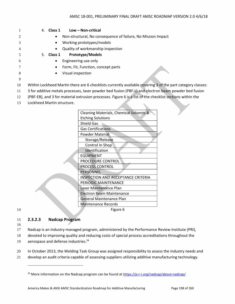
AMSC 18-001, PRELIMINARY FINAL DRAFT AMSC ROADMAP VERSION 2.0 4/6/18
America Makes & ANSI AMSC Standardization Roadmap for Additive Manufacturing Page 198 of 260
4. Class 1 Low – Non-critical 1
Non-structural, No consequence of failure, No Mission Impact 2
Working prototypes/models 3
Quality of workmanship inspection 4
5. Class 1 Prototype/Models 5
Engineering use only 6
Form, Fit, Function, concept parts 7
Visual inspection 8
9
Within Lockheed Martin there are 6 checklists currently available covering 3 of the part category classes: 10
3 for additive metals processes, laser powder bed fusion (PBF-L) and electron beam powder bed fusion 11
(PBF-EB), and 3 for material extrusion processes. Figure 6 is a list of the checklist sections within the 12
Lockheed Martin structure. 13
Cleaning Materials, Chemical Solvents & Etching Solutions
Shield Gas
Gas Certifications
Powder Material
Storage/Release
Control In Shop
Identification
EQUIPMENT
PROCEDURE CONTROL
PROCESS CONTROL
PERSONNEL
INSPECTION AND ACCEPTANCE CRITERIA
PERIODIC MAINTENANCE
Laser Maintenance Plan
Electron Beam Maintenance
General Maintenance Plan
Maintenance Records
Figure 6 14
2.3.2.3 Nadcap Program 15
16
Nadcap is an industry managed program, administered by the Performance Review Institute (PRI), 17
devoted to improving quality and reducing costs of special process accreditations throughout the 18
aerospace and defense industries.24 19
In October 2013, the Welding Task Group was assigned responsibility to assess the industry needs and 20
develop an audit criteria capable of assessing suppliers utilizing additive manufacturing technology. 21
24 More information on the Nadcap program can be found at https://p-r-i.org/nadcap/about-nadcap/
AMSC 18-001, PRELIMINARY FINAL DRAFT AMSC ROADMAP VERSION 2.0 4/6/18
America Makes & ANSI AMSC Standardization Roadmap for Additive Manufacturing Page 199 of 260
Analysis demonstrated that the Task Group would be best suited developing an audit criteria to assess 1
laser and electron-beam powder bed variants of the process. During the period 2014 to 2016, a sub-2
team of the Task Group, as well as invited industry experts, including equipment and powder 3
manufacturers, developed and verified various drafts of checklists via trial audits. This culminated in the 4
approval of the checklist AC7110/14, Nadcap Audit Criteria for Laser and Electron Beam Metallic Powder 5
Bed Additive Manufacturing, which was released for use in early 2017. 6
Concurrent with the checklist development, existing welding auditors were theoretically and practically 7
trained in the technology and then examined to qualify them to conduct audits to this new checklist. 8
Audits already have been performed and suppliers accredited to the checklist. 9
The Task Group has received several comments on the existing checklist and begun the process of 10
revising it to incorporate changes. Once industry standards become available, the Task Group will again 11
review the checklist to ensure that it adequately meets industry requirements. 12
The AC7110/14 checklist is available for downloading at no charge to any person registered in eAuditNet 13
(www.eauditnet.com). Once registered, the checklist can be found via Resources / Documents / Audit 14
Criteria / Welding. In addition to AC7110/14, AC7110, Nadcap Audit Criteria for Welding/Torch and 15
Induction Brazing and Additive Manufacturing, should also be downloaded as AC7110 is a core checklist 16
required for all of the welding checklists. 17
2.3.2.4 Aerospace Mission Assurance Information Workshop (MAIW) 18
19
The Aerospace Corporation sponsors a yearly workshop involving subject matter experts (SMEs) from 20
the U.S. space community that come together and evaluate specific mission assurance issues important 21
to the space enterprise. Examples of previous topics include counterfeit parts prevention strategies, root 22
cause investigation best practices guide, and supplier risk evaluation and control. For each topic of 23
interest, a team is created that is composed of SMEs from various industry, academic, and government 24
institutions. The team is charged with addressing the particular question of interest culminating in an 25
out brief to the community and a final report. 26
In August 2015, a team was stood up for a 3-month term to examine mission assurance considerations 27
relative to additive manufacturing. Because of the short timeframe, the team realized that this would 28
need to be an initial study that could feed into a more comprehensive evaluation during future MAIW 29
workshops. For a starting point, the members of the team polled their SMEs to come up with a group of 30
questions specific to potential risks of utilizing AM technologies. The goal was to help mission assurance 31
professionals, who are not necessarily subject matter experts, to begin to understand AM-specific issues 32
that need to be addressed when evaluating the insertion of AM parts into flight systems. To that end, 33
every question was supported with a background statement, a short discussion of the issue, and an 34
assessment of the criticality of the issue. More than 50 questions were captured in a chart deck that at 35
the time of this writing was currently in the final clearance process but will eventually be available to the 36
community. 37
AMSC 18-001, PRELIMINARY FINAL DRAFT AMSC ROADMAP VERSION 2.0 4/6/18
America Makes & ANSI AMSC Standardization Roadmap for Additive Manufacturing Page 200 of 260
2.3.2.5 Composite Materials Handbook-17 (CMH-17) and Metallic Materials Properties 1
Development and Standardization (MMPDS) Handbook 2
3
These two guidance documents are heavily used as part of the qualification process for metal and 4
composite materials. These documents both are based in volunteer organizations that have been active 5
for decades in rigorously reviewing data and statistical analyses for publication of design allowables. 6
As additively manufactured materials are expanding into regulated areas, these handbook organizations 7
are considering the inclusion of design allowables and qualification and certification guidance. AM data 8
are not currently available in either handbook; however, both organizations are considering including 9
them in future revisions. 10
Composite Materials Handbook -17 (CMH-17) 11
History: CMH-17 has a long history beginning in 1943 with the initial publication of the Army-Navy-12
Commerce (ANC) Bulletin 17 Plastics for Aircraft (Air Force, Navy, and Civil Aeronautics Document). In 13
1959, the handbook “MIL-HDBK-17 Plastics for Air Vehicles” was first released utilizing content from the 14
ANC Bulletin. In 1978, an industry and government group (Coordination Group) was formed followed by 15
the release of MIL-HDBK-17B Volume 1 in 1988. Since that time, several revisions and volumes have 16
been published included polymer matrix, metal matrix, ceramic matrix, and structural sandwich 17
composites. In 2012, the Handbook name was formally changed from MIL-HDBK-17 to CMH-17 and is 18
now published by SAE. There are currently 6 volumes in the series. 19
Since the first publication of the CMH-17, the goal has been to create, publish, and maintain proven, 20
reliable engineering information and standards subjected to a thorough technical review, and to support 21
the development and use of composite materials and structures. The Handbook has been successful in 22
maintaining a volunteer organization of experts and publishing the information to the international 23
composites community. Through training and tutorials, CMH-17 has extended its reach to suit user 24
needs. Additional information is available at www.cmh17.org. 25
Role in Certification: CMH-17 is an accepted source for composite material allowables recognized by the 26
FAA. FAA AIR100-2010-120-003 states that NCAMP design allowables are acceptable for showing 27
compliance with polymer matrix composites and they must be validated as being applicable for an 28
applicant’s application by the provisions listed in AIR100. Although CMH-17 is not specifically listed in 29
AIR100, CMH-17 has adopted NCAMP procedures. The material values published in CMH-17 are not 30
acceptable for design unless applicants follow the equivalency procedures provided in NCAMP and 31
CMH-17 to validate that the published values are applicable for that applicant’s product. 32
Content: CMH-17 is an evolving document that reflects the state of the art in composite materials. 33
Periodic updates are made to maintain updated references to proven standards and engineering 34
practices, as well as up-to-date reliable composites data. Current areas of development include adhesive 35
bonding guidance and data, and new materials data linked to publically-available material and process 36
specifications. 37
AMSC 18-001, PRELIMINARY FINAL DRAFT AMSC ROADMAP VERSION 2.0 4/6/18
America Makes & ANSI AMSC Standardization Roadmap for Additive Manufacturing Page 201 of 260
Additive Polymers: As part of a Federal Aviation Administration (FAA) led effort, qualification data of a 1
polymer AM material is being generated and will be submitted to CMH-17 for consideration. Submission 2
to the handbook will likely occur in 2018 and will require substantial review prior to publication. A 3
separate group under CMH-17 will drive the development effort of this new Volume to include 4
statistically reduced data and guidelines for both filled and unfilled polymer AM materials. Note: CMH-5
17 is mainly devoted to composite materials. Composites, as additive manufactured polymers, are 6
considered as being process dependent materials. This being the case, material values published in 7
CMH-17 are not acceptable for design unless applicants follow the equivalency procedures provided in 8
CMH-17 to validate that the published values are applicable for that applicant’s product. It is expected 9
that values published for AM polymers will be subjected to these same procedures. 10
Metallic Materials Properties Development and Standardization (MMPDS) Handbook 11
History: MMPDS also has a long history beginning with ANC-5 published in 1937. The United States Air 12
Force (USAF) assumed primary responsibility for continuing development of the Handbook in 1954, 13
recruited Battelle Memorial Institute as secretariat and changed the program name to MIL-HDBK-5 in 14
1956. Battelle has maintained and published the Handbook since 1957, serving as an impartial agent to 15
collect and analyze industry data and to publish statistically valid design allowables. In 1997 the 16
Industrial Steering Group (ISG) was formed to supplement government funding. In 2003, the Federal 17
Aviation Administration took over the government oversight role and changed the name of the 18
document to the Metallic Materials Properties Development and Standardization (MMPDS) Handbook. 19
The ISG is currently composed of 38 companies from 12 countries. The Government Steering Group 20
(GSG) includes representatives of the FAA, US Air Force, US Navy, and NASA. Additional information is 21
available at www.mmpds.org. Together, the ISG and GSG form the MMPDS Coordinating Committee. 22
Role in Certification: The MMPDS Handbook is an accepted source for metallic material and fastener 23
system allowables recognized by the FAA, all departments and agencies of the Department of Defense 24
(DoD), and the National Aeronautics and Space Administration (NASA) within the limitations of the 25
certification requirements of the specific government agency. Per FAA Memorandum PS-AIR-MMPDS: 26
(Subject: Metallic Material Properties Development and Standardization (MMPDS) Handbook) A and B-27
basis design values are acceptable for compliance for material strength properties and design values for 28
aircraft certification and continued airworthiness without further showing of compliance. 29
Content: The Handbook contains design information on the mechanical and physical properties of 30
metallic materials and joints commonly used in aircraft and aerospace vehicle components and 31
structures. Chapter 9 (Guidelines) documents the test standards, data requirements, and statistical 32
algorithms required for consideration for each type of property reported. For example, A-/B-Basis static 33
strength values require no less than 100 tests with material drawn from 10 heats/10 lots of metal 34
assuming that the data fit an approved probability distribution function. Test data generated by industry 35
suppliers and users are submitted to Battelle for analysis using guidelines documented in MMPDS 36
Chapter 9. Results are reviewed at twice yearly MMPDS coordination meetings for approval. These 37
coordination meetings are open to the public. Each year, new alloys are added, guidelines are updated, 38
and revisions are made to existing sections after ISG and GSG review and approval. 39
AMSC 18-001, PRELIMINARY FINAL DRAFT AMSC ROADMAP VERSION 2.0 4/6/18
America Makes & ANSI AMSC Standardization Roadmap for Additive Manufacturing Page 202 of 260
Additive Metals: MMPDS has had limited exposure to a couple of additive manufacturing materials, 1
analyzing data beginning with SAE AMS4999. However, at the time, the data submitted did not meet the 2
existing data requirements which would allow publication of data in the Handbook. At present, no 3
additively manufactured alloys are contained in the Handbook. The unique nature of additive 4
manufacturing materials requires a different approach for deriving supportable material allowables then 5
those applied to more traditional metal alloys. To that end, approaches more applicable for AM 6
materials are being discussed in a working group devoted to process intensive materials. The Emerging 7
Technology Working Group (ETWG), composed of interested ISG and GSG organizations, is seeking to 8
develop an approach for driving supportable material allowables for AM materials. Initial efforts have 9
been made on presentation of the data, equivalency determination methods, and other general 10
guidance. Guidelines for Emerging Materials and Technologies, which closed Agenda Item 11-40, 11
summarizes proposed data presentation, equivalency determination, and other general guidance. The 12
proposal was not adopted by MMPDS as it was determined that defining generic guidelines for additive 13
metals was premature due to significant gaps in both technology and infrastructure. For example, 14
inclusion in MMPDS is predicated upon the existence of public specifications. In the case for AM, both 15
the feedstock material and processing standards were not generally available. Few specifications exist 16
and data sets submitted to Battelle have been judged under current MMPDS procedures to be 17
inadequate for deriving publishable allowables. In general, there are no approved MMPDS guidelines 18
currently by which the MMPDS organization can generate an allowable warranting the government 19
approved “A- or B-Basis” values. Currently, the MMPDS organization is assessing if AM materials could 20
be published in a separate volume or document with special guidance more suited to AM materials then 21
those currently applied to more traditional materials. Battelle continues to solicit input from industry 22
and government entities on suitable guidelines and data to validate those guidelines in this proposed 23
new volume. 24
2.3.2.6 AWS D20 25
26
The American Welding Society (AWS) assigned a task group to study whether or not AM fell within its 27
charter and whether there was a need for standards developed by AWS. It was emphasized that there 28
should not be duplication of effort and the AWS committee would develop broader application 29
codes/standards that would integrate requirements for AM of metals, including requirements for 30
design, qualification, fabrication, and inspection. It was decided that a standalone committee was 31
needed for the creation of an AM standard and the D20 committee was formed at the end of 2013. 32
The AWS D20 committee is creating a comprehensive document that identifies requirements for AM 33
procedure qualification and AM machine operator qualification, as well as fabrication and inspection 34
requirements for AM components. The D20 committee intends for the standard to cover both powder 35
bed fusion and directed energy deposition metal AM processes. A graded approach is being taken, with 36
three different component classifications that determine the level of qualification and inspection 37
requirements. 38
At the AWS D20 committee meeting in October 2017, comments were addressed from the first ballot of 39
the draft standard. The draft standard is currently in the second round of balloting within the 40
AMSC 18-001, PRELIMINARY FINAL DRAFT AMSC ROADMAP VERSION 2.0 4/6/18
America Makes & ANSI AMSC Standardization Roadmap for Additive Manufacturing Page 203 of 260
committee. After the committee members have voted to approve the document, it will go to the AWS 1
Technical Activities Committee (TAC) for vote. 2
2.3.2.7 NASA Marshall Space Flight Center (MSFC) Standard for Additively Manufactured 3
Spaceflight Hardware by Laser Powder Bed Fusion in Metals 4
5
Motivations 6
NASA human rated spaceflight programs have quickly embraced the promise of AM to benefit design 7
flexibility, cost, and schedule challenges of system development and manufacture. Each of NASA’s 8
current human spaceflight programs, the Space Launch System, Orion Spacecraft, and the Commercial 9
Crew Program is developing AM hardware and establishing a significant future role for AM in these 10
systems. In many cases, the timeline for qualification of this early AM hardware and certification of its 11
associated systems has been condensed compared to the typical introduction of new manufacturing 12
technology. Select pieces of flight hardware have already been produced and continued production of 13
AM flight hardware is imminent. 14
As is common across industry, the objectives and schedules of programs have been leading the 15
development of AM requirements and have been embracing an AM adoption agenda that challenges 16
the pace of AM process understanding itself. This creates a significant pull on engineering organizations 17
to establish a framework for AM requirements while process understanding evolves. From the 18
perspective of a certifying agency, the absence of requirements creates significant issues including a lack 19
of adequate review products and ambiguity in the evaluation of available products, lack of consistency 20
across programs and even internal to programs, poorly integrated flight rationale for certification logic, 21
and contractual uncertainty including loss of contractual leverage. 22
NASA has endeavored to engage the efforts of industry standards development organizations (SDOs) as 23
each has become involved in AM, and NASA continues to actively support these efforts. It has been clear 24
that standards from SDOs will eventually play a key role in governing the AM process for NASA 25
spaceflight hardware, just as they do for most all other processes. However, none have yet become 26
sufficiently mature to adopt independently and there remains a significant need to frame the overall AM 27
process in the context of NASA’s overarching standards for materials, structures, and fracture control. 28
Objectives and Content 29
The primary objective of the NASA document, developed by the NASA Marshall Space Flight Center 30
(MSFC), is to provide an overarching framework of methodologies to meet the intent of existing 31
requirements in materials, structures, and fracture control for AM parts produced with the laser powder 32
bed fusion process. The document has been publicly available in draft form since mid-2015. It was 33
published in October 2017 as two documents: a standard MSFC-STD-3716, Standard for Additively 34
Manufactured Spaceflight Hardware by Laser Powder Bed Fusion in Metals, and an associated 35
specification MSFC-SPEC-3717, Specification for Control and Qualification of Laser Powder Bed Fusion 36
Metallurgical Processes. 37
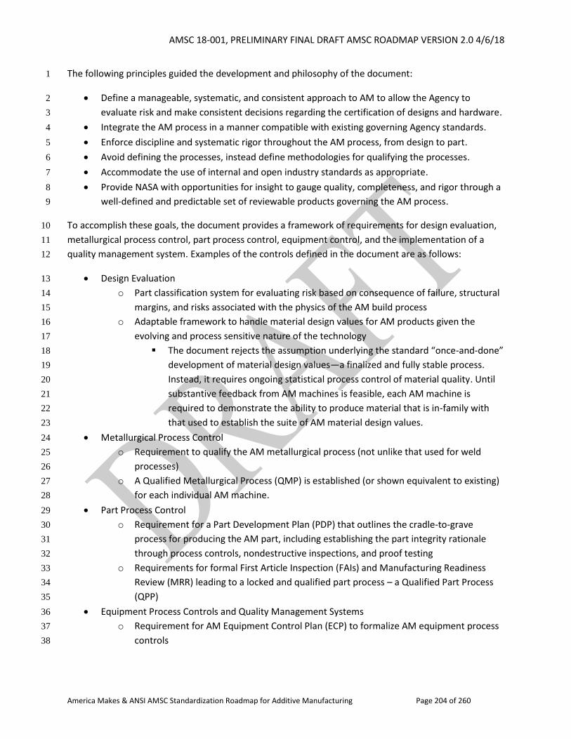
AMSC 18-001, PRELIMINARY FINAL DRAFT AMSC ROADMAP VERSION 2.0 4/6/18
America Makes & ANSI AMSC Standardization Roadmap for Additive Manufacturing Page 204 of 260
The following principles guided the development and philosophy of the document: 1
Define a manageable, systematic, and consistent approach to AM to allow the Agency to 2
evaluate risk and make consistent decisions regarding the certification of designs and hardware. 3
Integrate the AM process in a manner compatible with existing governing Agency standards. 4
Enforce discipline and systematic rigor throughout the AM process, from design to part. 5
Avoid defining the processes, instead define methodologies for qualifying the processes. 6
Accommodate the use of internal and open industry standards as appropriate. 7
Provide NASA with opportunities for insight to gauge quality, completeness, and rigor through a 8
well-defined and predictable set of reviewable products governing the AM process. 9
To accomplish these goals, the document provides a framework of requirements for design evaluation, 10
metallurgical process control, part process control, equipment control, and the implementation of a 11
quality management system. Examples of the controls defined in the document are as follows: 12
Design Evaluation 13
o Part classification system for evaluating risk based on consequence of failure, structural 14
margins, and risks associated with the physics of the AM build process 15
o Adaptable framework to handle material design values for AM products given the 16
evolving and process sensitive nature of the technology 17
The document rejects the assumption underlying the standard “once-and-done” 18
development of material design values—a finalized and fully stable process. 19
Instead, it requires ongoing statistical process control of material quality. Until 20
substantive feedback from AM machines is feasible, each AM machine is 21
required to demonstrate the ability to produce material that is in-family with 22
that used to establish the suite of AM material design values. 23
Metallurgical Process Control 24
o Requirement to qualify the AM metallurgical process (not unlike that used for weld 25
processes) 26
o A Qualified Metallurgical Process (QMP) is established (or shown equivalent to existing) 27
for each individual AM machine. 28
Part Process Control 29
o Requirement for a Part Development Plan (PDP) that outlines the cradle-to-grave 30
process for producing the AM part, including establishing the part integrity rationale 31
through process controls, nondestructive inspections, and proof testing 32
o Requirements for formal First Article Inspection (FAIs) and Manufacturing Readiness 33
Review (MRR) leading to a locked and qualified part process – a Qualified Part Process 34
(QPP) 35
Equipment Process Controls and Quality Management Systems 36
o Requirement for AM Equipment Control Plan (ECP) to formalize AM equipment process 37
controls 38
AMSC 18-001, PRELIMINARY FINAL DRAFT AMSC ROADMAP VERSION 2.0 4/6/18
America Makes & ANSI AMSC Standardization Roadmap for Additive Manufacturing Page 205 of 260
o Requirement for the integration of an AS9100 (or equivalent) Quality Management 1
System (QMS) throughout the AM process 2
The resulting products of these controls (QMP, PDP, QPP, ECP, etc.) provide a consistent and 3
quantifiable set of deliverables for the Agency to reliably evaluate the implementation of AM parts. 4
2.3.2.8 ASME Y14.46 5
6
ASME Y14.46, Product Definition for AM, is a subcommittee formed by the ASME Y14 Engineering 7
Product Definitions and Related Documentation Committee. The Y14.46 document addresses Product 8
Definition requirements that are specific to AM as well as requirements not specific to, but elevated 9
because of, AM. The sections reflect four project teams (PT): 1) Part Definition, 2) Process, 3) 10
Verification and Conformance, and 4) Data Package Requirements. 11
The Verification and Conformance Section provides guidance on conformance to specifications for AM 12
products, in particular manufacturing imperfections meeting acceptable ranges, specified key 13
characteristics, and identification of acceptance criteria specific to using AM processes and the 14
associated level of reliability. 15
Surface finish specifications and inspection methodologies (including NDE, laser, non-contact, etc.) will 16
continue to be developed by the ASME B46 Dimensional Metrology Standards Committee. 17
The Y14.46 standard was published on November 17, 2017. This draft standard for trial use will be 18
available for one year for comments.25 Following the one year period, all comments received will be 19
submitted to the Y14.46 Committee. The committee plans to revise the standard based on the 20
comments received. 21
2.3.2.9 Underwriters Laboratories (UL) 22
23
Underwriters Laboratories (UL) is accredited by the American National Standards Institute (ANSI) as an 24
audited designator. UL promulgates the standard for safety ANSI/UL746C, Standard for Polymeric Materials 25
– Use in Electrical Equipment Evaluations, Seventh Edition, dated February 5, 2018. This standard is 26
maintained by the UL746C Standards Technical Panel composed of various interests including: 27
authorities having jurisdiction, commercial/industrial users, producers, consumers, supply chain, 28
testing/standards organizations, and general interests. 29
Standard 30
ANSI/UL746C contains requirements for parts fabricated from polymeric materials used to construct 31
electrical equipment. The standard describes test procedures for fabricated polymeric parts in specific 32
25 See https://www.asme.org/career-education/media/training/y1446-recommended-use-additive-manufacturing for a recorded webinar on “Why Y14.46 is recommended for use in AM.”
AMSC 18-001, PRELIMINARY FINAL DRAFT AMSC ROADMAP VERSION 2.0 4/6/18
America Makes & ANSI AMSC Standardization Roadmap for Additive Manufacturing Page 206 of 260
applications to evaluate specific criteria. The standards’ scope includes parts made by additive 1
manufacturing technology. 2
End-Product Evaluations 3
ANSI/UL746C specifies that end-product parts, or test specimens cut from the end-product parts, be 4
subjected to various tests, or application of historical data, for qualification. The following properties 5
may be addressed at the end-product level evaluation: 6
Thermal endurance 7
Electric strength / Volume Resistivity 8
Impact resistance 9
Flammability 10
Tracking resistance 11
Resistance to electrical ignition sources 12
Permanence 13
UV & water/weathering resistance 14
Dimensional stability 15
Pre-Selection Data 16
UL also conducts material certification for preselection purposes. ANSI/Ul746C specifies test specimens 17
printed, or cut from a printed part, in the specified dimensions may represent the end-product 18
applications where identical production parameters are used. 19
UL also administers a component recognition program category for plastics used for additive 20
manufacturing entitled: “[Plastics - Component] Plastics for Additive Manufacturing – Component 21
(QMTC2).” Materials certified under this category are identified by the material manufacturer and grade 22
designation. 23
Process parameters that are also specified, dependent on process, typically include: 24
Printer make & model 25
Build plane 26
Layer thickness 27
Hatch spacing 28
Post process method(s) 29
Infill 30
Raster angle 31
Print speed 32
Laser power 33
Air gap 34
Scan strategy 35
36
AMSC 18-001, PRELIMINARY FINAL DRAFT AMSC ROADMAP VERSION 2.0 4/6/18
America Makes & ANSI AMSC Standardization Roadmap for Additive Manufacturing Page 207 of 260
2.3.3 User Group/Industry Perspectives on Q&C 1
2
Whereas the prior section addressed focused efforts underway to develop guidance documents on 3
qualification and certification, this section endeavors to tie perspectives together by industry sector. 4
Philosophies and needs of three sectors (aerospace, defense, and medical) are discussed and gaps are 5
identified. 6
2.3.3.1 Aerospace Industry 7
8
The aerospace industry is different from other industries in that space based parts typically cannot be 9
recalled and parts must withstand space environments. Human space flight poses unique safety 10
concerns and therefore requires more stringent flight qualification than other industries. The intended 11
use of the product dictates the rigor of the material and part qualification categories. 12
Most flight components will be metal structural/flight components such as titanium or aluminum, so this 13
should be a priority for standards development. ULTEMTM 9085 is also being used for non-structural 14
flight parts. Many aerospace industry components will include integration of mixed materials. 15
Materials 16
Typical industry practice is that precursor materials are “certified” (qualified) and/or verified, though 17
FAA only certifies final products. Material certification standards in existence can be used as is, with 18
modifications, or as a point of departure for new standards for AM materials. Normally, material 19
suppliers certify their materials to these standards and the buyers verify the certification. These 20
certifications are to be included in the data package required for qualification and certification of the 21
AM processed part. AM material properties are highly dependent on process/machine variables as well 22
as post-processing. 23
Parts/Products 24
Parts/products are qualified and verified. The part qualification process achieves a product certification, 25
which ensures the product meets all technical requirements. Part qualification is typically governed by 26
program/customer technical requirements and standards. 27
Product verification requirements define activities to minimize risk and certify that the delivered system 28
or product satisfies hardware, software, and system requirements, as qualified. Each product goes 29
through verification, also known as product acceptance, to ensure requirements are met during or after 30
the build process by performing an inspection, demonstration, analysis, or test. These verification 31
activities are often performed to standards (e.g., ASTM, etc.). Product verification may include 1st article 32
inspection to demonstrate the suitability of 1st time use by performing additional inspection, test, and 33
demonstration activities. 34
Gap QC2: AM Part Classification System for Consistent Qualification Standards. A part classification 35
system is used to describe the level of risk associated with a part and may therefore be used as a metric 36
AMSC 18-001, PRELIMINARY FINAL DRAFT AMSC ROADMAP VERSION 2.0 4/6/18
America Makes & ANSI AMSC Standardization Roadmap for Additive Manufacturing Page 208 of 260
to gauge appropriate qualification requirements. A common classification system for AM parts by 1
industry sector is needed to provide consistent evaluation criteria for AM part risk. This should include a 2
definition of criticality levels. Consistent risk criteria provide the basis for consistent expectations and 3
levels of qualification rigor. Examples of classification systems can be found in the Lockheed Martin AM 4
supplier quality checklist and NASA’s MSFC-STD-3716, Standard for Additively Manufactured Spaceflight 5
Hardware by Laser Powder Bed Fusion in Metals, and the draft AWS D20.1 standard, which utilizes the 6
part classification system identified in AWS D17.1/D17.1M:2017-AMD1, Specification for Fusion Welding 7
of Aerospace Applications. Any industry requiring rigorous AM part qualification and system certification 8
would benefit from a common part classification system. 9
R&D Needed: No 10
Recommendation: A common classification system for AM parts should be defined along with the 11
recommended minimum process and part qualification requirements commensurate with part risk for 12
each classification level. 13
Priority: High 14
Status of Progress: Not started 15
Update: Writing a standard will be a challenge and will require coordination between the SDOs and 16
relevant federal agencies. It may also be application-specific (e.g., spaceflight, military, etc.) It could be a 17
series of documents from the agencies. This is more a harmonization issue. Procurement and level of 18
testing required need to be addressed. The primary beneficiaries will be industry. 19
Organization: ASTM F42/ISO TC 261, AWS, DoD, FAA, NASA, SAE 20
Processes or Procedures 21
Each implementation of an AM process requires qualification prior to use in most aerospace 22
applications. An implementation of an AM process may be referred to as an AM procedure, such as the 23
case of the AWS D20 standard, which inherits its terminology from AWS D17.1 regarding welding 24
procedure qualification. Process or procedure qualification is essential to ensure the fundamental 25
integrity of material produced by any given AM machine under a fully defined and fixed process. There is 26
currently no consensus definition for the qualification of additive processes. This lack of standard 27
definition presents a risk to the additive user community in aerospace by introducing significant 28
variation in the evaluations included in the qualification methodology. This renders process qualification 29
largely vendor-specific, and requires a case-by-case evaluation of the qualification methodology for any 30
given set of requirements. A vendor’s assertion of qualified additive processes does not, in and of itself, 31
provide meaning if not presented with the specifics of the qualification methodology. A few common 32
examples of variations in the additive process/procedure qualification methodology include the degree 33
of internal material quality assessment (microstructure, porosity, lack of fusion, etc.), the degree of 34
mechanical property evaluation (tensile, fatigue, fracture toughness, etc.), degree of evaluation in the 35
AMSC 18-001, PRELIMINARY FINAL DRAFT AMSC ROADMAP VERSION 2.0 4/6/18
America Makes & ANSI AMSC Standardization Roadmap for Additive Manufacturing Page 209 of 260
quality of surfaces and rendered details, and the extent of build quality evaluation throughout the 1
available build area/volume. 2
The definition of the actual process or procedure being qualified often lacks consistency. For example, 3
feedstock controls and thermal processes may, or may not, be included in the definition. Such precursor 4
and successor steps to the base AM process are critical if the process qualification is intended to 5
guarantee fundamental material performance. 6
Different approaches also exist in the aerospace industry regarding the distinction between the 7
qualification of additive parts and the foundational processes/procedures. A few examples are listed 8
below: 9
NASA: The NASA document, MSFC-STD-3716, Standard for Additively Manufactured Spaceflight 10
Hardware by Laser Powder Bed Fusion in Metals (See section 2.3.2.7), separates the qualification of the 11
foundational PBF-L process (as described by MSFC-SPEC-3717, Specification for Control and Qualification 12
of Laser Powder Bed Fusion Metallurgical Processes) from the qualification of an additive part, which is 13
considered a geometry-specific implementation of the qualified process. The part then requires its own 14
part-specific qualifications to demonstrate successful implementation of the process. 15
AWS: By contrast, the developing AWS D20 standard requires the qualification of the AM procedure 16
used to produce a component, where the qualified procedure must contain all variables required to 17
fabricate the component, such as the build model, feedstock and build platform characteristics, AM 18
machine variables, build environment requirements, build parameters, and component post-processing. 19
In this scenario, the AM procedure is part-specific and is qualified through the fabrication and evaluation 20
of test articles. 21
SAE: The SAE AMS AM-M (metallic) specifications under development are hierarchical and define the 22
requirements and establish controls for a material process combination. They are based on a material 23
specification, including material requirements. Each material specification is linked to a separate process 24
and feedstock specifications, as well as a feedstock process specification. The SAE AMS AM-P (polymer) 25
specifications are similar with a base material specification that is linked to a process specification. In 26
addition, there are separate detailed material specifications that include the specification minimum 27
values for specific material/process combinations. For further information on the SAE specification 28
approach, see Section 1.5.11 of this Roadmap. 29
Personnel 30
Personnel are “certified.” Currently, operator certification is through on the job training coupled with 31
OEM-provided training (classroom and hands on experience) specific to particular machines/equipment. 32
Procedures may be written to document how personnel certifications are accomplished. Some 33
certifications include levels of certification that determine the specific activities/operations that an 34
operator can perform, such as product acceptance, equipment maintenance, or certification of other 35
operators. Future needs may call for formal personnel certification by process, or process and material, 36
as well as for specific machines. AWS D20 has a section on qualification of AM machine operators as well 37
AMSC 18-001, PRELIMINARY FINAL DRAFT AMSC ROADMAP VERSION 2.0 4/6/18
America Makes & ANSI AMSC Standardization Roadmap for Additive Manufacturing Page 210 of 260
as the operator certifications described in the NASA MSFC standard for laser powder bed fusion for AM. 1
ASTM offers a general AM certification and may also be looking at other certifications. The aerospace 2
and defense industries are aligned in their approach to personnel certification, so the gap identified in 3
the Defense Industry section below is applicable. 4
AM Equipment 5
AM equipment is calibrated and/or certified by the OEM or aerospace industry company that purchases 6
the equipment per certification and/or calibration procedures. Some companies refer to calibration as 7
certification. 8
Adverse machine environmental condition standards are needed so the build environment can be 9
compared to the as specified parameters for environmental control through methods such as chamber 10
gas, temperature, and pressure monitoring. Gaps for adverse machine environmental condition 11
standards are addressed in the Process Control section of this roadmap. 12
The aerospace industry needs additively manufactured physical calibration standards for NDE. Those 13
standards are covered in the NDE section of this roadmap. 14
AM Drawing and Model Standards 15
It is anticipated that the aerospace industry will adopt industry standards for drawings and for DSR4 and 16
DSR 6 (no drawing) models. It is anticipated that only models will be needed in the future and the 17
models will cover all aspects currently in the drawings and will include things like x,y,z orientation, 18
growth direction, etc. Drawing and model standards are needed so the as-built models can be compared 19
to the as-designed models for product acceptance through inspection methods such as 3D scanning and 20
CT scanning. Gaps for drawing and model standards are addressed in the Design section of this 21
roadmap. 22
2.3.3.2 Defense Industry 23
As part of Defense Acquisition, anything going onto a ship, aircraft, submarine, ground vehicle, or 24
otherwise employed by our military forces goes through varying levels of Q&C prior to deployment. 25
Even commercial or non-developmental items have to be tested to make sure they meet the technical 26
and performance requirements demanded by the platform. For example, any new aircraft undergoes 27
rigorous developmental and operational testing before fielding, no matter the origin of the item on the 28
platform. Components are tested individually, as part of a system, perhaps integrated into an avionics 29
suite or green weight airframe as appropriate, then flight tested as appropriate before a decision is 30
made for full rate production. This happens regardless of how that part is manufactured. There are 31
additional Q&C burdens for AM developed or manufactured parts arising from the lack of specifications 32
and standards for the various AM processes, the precursor materials used in AM processes, the finishing 33
and post-processing of AM parts, and nondestructive evaluation criteria. These gaps are being 34
addressed within this document. There are also no established design allowables for AM processes, 35
AMSC 18-001, PRELIMINARY FINAL DRAFT AMSC ROADMAP VERSION 2.0 4/6/18
America Makes & ANSI AMSC Standardization Roadmap for Additive Manufacturing Page 211 of 260
which results in much higher requirements for Q&C to have the baseline understanding of the material 1
properties of a given part and whether or not that part will meet the established performance criteria. 2
The Secretary of the Navy (SECNAV) has formed an AM Executive Committee (EXCOMM) comprised of 3
leadership that includes the System Commands, Fleet Units, and the R&D community with the intent of 4
ultimately integrating AM into Defense Acquisition. One of the stated goals of the EXCOMM is to 5
“Develop the ability to qualify and certify AM parts.” This encompasses several focus areas, including 6
broadening the library of materials, processing, material properties, nondestructive evaluation, 7
standards/specifications development, manufacturing process control, and expeditionary and afloat 8
environmental effects. These goals and their associated efforts are captured in the Department of the 9
Navy (DON) AM Implementation Plan. 10
In addition, the Defense Logistics Agency has expressed strong support for use of AM for acquisition, 11
particularly in manufacturing decades old legacy parts that no longer have a supporting industrial base. 12
However, the technical data associated with these parts is usually found as 2D blueprints, thus requiring 13
a conversion to 3D models. In addition to the added cost of this process, current methods of converting 14
to 3D data introduces errors that increase the complexity of the certification process. 15
Technical Data Package (TDP) 16
A TDP is defined by the Defense Acquisition University as: “A technical description of an item adequate 17
for supporting an acquisition strategy, production, engineering, and logistics support (LS). The 18
description defines the required design configuration and procedures to ensure adequacy of item 19
performance. It consists of all applicable TD such as drawings, associated lists, specifications, standards, 20
performance requirements, quality assurance (QA) provisions, and packaging details.” A TDP is used to 21
contract out for the procurement of parts and components for DoD assets. 22
There are several ongoing efforts throughout the Navy that are geared towards the development of a 23
common TDP. The goal of developing this TDP is to encompass all the necessary data to allow for 24
competitive bidding for parts to be additively manufactured, while ensuring that there is enough detail 25
and information within the TDP to produce the same exact part with the same properties that fall within 26
the specified tolerances and requirements from any vendor. The development of a common TDP will not 27
be possible without specifications and standards that can be invoked to guide the manufacturing 28
process. 29
In order to achieve the goal of producing accurate parts repeatedly, a certified TDP format must be 30
developed and proven. This certified TDP format will increase certainty of acquiring repeatedly accurate 31
components as well as providing the logistics communities the ability to successfully order additively 32
manufactured components in the future. Current Navy efforts include developing a part and process 33
agnostic TDP format that will aid in the overall process for manufacturing components via additive 34
manufacturing (regardless of criticality). It is understood that there are a number of challenges 35
associated with developing a process-agnostic TDP. See the discussion in the Design Documentation 36
section of this roadmap for Gap D17 on TDPs. 37
AMSC 18-001, PRELIMINARY FINAL DRAFT AMSC ROADMAP VERSION 2.0 4/6/18
America Makes & ANSI AMSC Standardization Roadmap for Additive Manufacturing Page 212 of 260
Neutral build files are the desired end state for build files that can be ported between different types of 1
machines/processes. See also Gap D20 on neutral build file. 2
Harmonizing Q&C Terminology for Process Parameters 3
Each machine manufacturer has their own set of terms that they use to describe the processing 4
parameters within their machine. Often, two identical process parameters will have different terms 5
associated with that parameter if you directly compare two machines made by different manufacturers. 6
In terms of standards in development, the AWS D20.1 standard is being balloted to the committee for 7
the second time. As noted earlier, it will include process parameters for PBF and DED processes. The SAE 8
AMS7000 series includes references to ISO/ASTM 52900 and ARP1917 Rev A. Specifically, in AMS 7003 9
Laser Powder Bed Fusion Process, Section 8.1 lists several additional definitions that are not included in 10
52900 or ARP1917. ASTM F42 also has a dedicated terminology subcommittee F42.91 working with 11
ISO/TC 261 on JG 51. Additional terms are being developed by SDOs to meet industry requirements. 12
Gap QC3: Harmonizing Q&C Terminology for Process Parameters. In order to enable full understanding 13
of the given processes and to include this type of information in a process-agnostic TDP, and for 14
purposes of qualification and/or certification, there must be standardization of process parameter 15
terminology across machine manufacturers. 16
R&D Needed: No 17
Recommendation: Develop standardized terminology for process parameters for use across all AM 18
equipment. Potentially, incorporate these into ISO/ASTM 52900:2015, Additive manufacturing - General 19
principles - Terminology. See also Gap PC5 on parameter control. 20
Priority: Medium 21
Status of Progress: Green 22
Update: As noted in the text. 23
Organization: ASTM F42/ISO TC 261 JG 51, AWS D20, SAE AMS-AM, IEEE-ISTO PWG 24
Source (i.e., Vendor) Approval 25
For Navy platforms, before a vendor can supply a component, that vendor must be qualified to 26
manufacture that part. Q&C necessarily is applied to the actual manufacturer, not a third party that may 27
act as a middleman or distributor. For every Source Approval Request (SAR) package, a vendor must 28
demonstrate manufacturing standards, first article test, and requisite performance testing within their 29
capacity to do so. The manufacturing methods for the part must be specified by the vendor along with 30
any other critical processes through the end of post-processing. This would include all of the parameters 31
needed to qualify or certify the final part. The government often requires additional environmental 32
testing, be it flight, seaworthiness, or electromagnetic compatibility. As AM continues to rapidly mature, 33
especially in the near term, it may be challenging for the government to keep up with the pace. 34
AMSC 18-001, PRELIMINARY FINAL DRAFT AMSC ROADMAP VERSION 2.0 4/6/18
America Makes & ANSI AMSC Standardization Roadmap for Additive Manufacturing Page 213 of 260
Therefore, industry and government will have to work together to understand the nuances of different 1
AM methods, and what needs to be qualified, tested, and demonstrated by an AM produced 2
component. ASTM has begun to populate the landscape with some standards, such as ASTM B962-17, 3
Standard Test Methods for Density of Compacted or Sintered Powder Metallurgy (PM) Products Using 4
Archimedes’ Principle, which has already undergone several revisions. 5
Certification of parts is governed by regulations for criticality and safety criteria based on the 6
application. Responsibility for certification of the components for the intended application needs to be 7
agreed to between the customer (DoD) and the supplier/manufacturer of the AM component. 8
Identified published standards include: ASTM B962-17 noted above and ASTM E384-17, Standard Test 9
Method for Microindentation Hardness of Materials. Standards in development include: ASTM 10
WK51329, New Specification for Additive Manufacturing Cobalt-28 Chromium-6 Molybdenum Alloy (UNS 11
R30075) with Powder Bed Fusion1, and other ASTM standards. 12
Gap QC4: DoD Source (i.e., Vendor) Approval Process for AM Produced Parts. As multiple methods of 13
AM continue to mature, and new AM techniques are introduced, the government will need to fully 14
understand the ramifications of each of these techniques, of what they are capable, and how certain AM 15
procedures might lend themselves to some classes of parts and not others. Thus, not only must the 16
government understand the differences, but how they should be assessed and tested, and what 17
additional checks must be made on the end product before it can be qualified for use in a military 18
platform. High pressures, temperatures, and other contained environments could impact the 19
performance or life of safety-critical parts in ways that are not understood. Today, more research is 20
required to determine the delta between traditional and AM methods. 21
R&D Needed: Yes 22
Recommendation: Starting with the most mature technologies, such as laser powder bed, develop 23
standards to assess required checks for levels of criticality and safety as part of the source approval 24
process. 25
Priority: High 26
Status of Progress: Not Started 27
Update: It will be a challenge to develop one generic standard. DoD will need to specify the certification 28
requirements that need to be put into such a standard and OEMs will need to share relevant 29
information. 30
Organization: ASME, ASTM F42/ISO TC 261, DoD, Industry, SAE, Service SYSCOMS 31
Machine Operator Training and Qualification 32
All potential users of an AM machine, auxiliary equipment, and related software need to undergo 33
appropriate training for their responsible areas. There may be different levels of operator training 34
AMSC 18-001, PRELIMINARY FINAL DRAFT AMSC ROADMAP VERSION 2.0 4/6/18
America Makes & ANSI AMSC Standardization Roadmap for Additive Manufacturing Page 214 of 260
required. AM machine operator competencies may include: feedstock material storage, safety, and 1
setup; machine calibration and maintenance; machine setup and operation; build cycle monitoring; and 2
interruption recovery. Re-training at some frequency also may be required. An internal training 3
database should be maintained and used to reflect operator competencies on each responsibility and to 4
ensure any changes in machine operation are accounted for in training updates. Periodic audits may be 5
used to validate that operation steps are being followed. Operator training has also been identified as a 6
need for the medical devices industry which may have different requirements (e.g., for point of care 7
providers). 8
In terms of existing standards and specifications, the NASA MSFC-SPEC-3717 addresses training and 9
certification of personnel for PBF-L operations. There is also SAE ARP 1962A-1995, Training and Approval 10
of Heat-Treating Personnel (reaffirmed: May 2007) though it is not AM specific. 11
The draft AWS D20.1 standard includes requirements for AM machine operator performance 12
qualification based on training, written and practical examinations, and the demonstration of successful 13
AM builds. It is being balloted to the committee for the second time. The SAE 7000 series also addresses 14
training. 15
AM training programs include but are not limited to those offered by OEMs and other third party 16
organizations. Underwriters Laboratories (UL), in cooperation with industry SMEs, for example, has 17
developed a multi-tiered program covering comprehensive introductory knowledge, technical and 18
business competencies, and hands-on application-based learning. The University of Louisville is host to 19
UL’s advanced hands-on training focused on metals. The program emphasizes the safe implementation 20
of AM and in collaboration with Tooling-U SME, includes the industry’s first Professional Certification. 21
ASME is also exploring machine operator training curriculum. 22
Gap QC5: Machine Operator Training and Qualification. There is a need for standards or guidelines 23
outlining AM training requirements. 24
R&D Needed: No 25
Recommendation: Develop AM operator training and qualification standards or guidelines. Training 26
should cover the various AM materials and processes available in the market and be performance based 27
to ensure consistent AM part quality. Develop additional standards for artisanal levels of competency 28
and experience, delineating an individual’s expertise in the field or subsets of the AM field. 29
Priority: Low 30
Status of Progress: Green 31
Update: As noted in the text. 32
Organization: NASA, SAE, AWS, OEMs, UL, ASTM F42/ISO TC 261, AAMI 33
AMSC 18-001, PRELIMINARY FINAL DRAFT AMSC ROADMAP VERSION 2.0 4/6/18
America Makes & ANSI AMSC Standardization Roadmap for Additive Manufacturing Page 215 of 260
In the specific case of DoD, consideration should be given to establishing a sub-specialty code for AM. 1
Concerns also include training for enlisted personnel, training tailored for specific AM machines (or 2
categories thereof), and materials as needed to complete mission requirements. Such a training course 3
should include: 4
Qualification 5
Software and CAD file preparation 6
Knowledge of machine and material limits 7
Machine calibration and maintenance (whether performed by the operator/vendor or the 8
machine OEM) 9
Proper material handling 10
Proper waste recycling/containment 11
Training in monitoring of the fabrication process 12
Part separation from the build plate 13
Post-processing (if performed by the operator/vendor) 14
Inspection/testing (if performed by the operator/vendor) 15
Safety precautions for AM machine and material use 16
Certification 17
Reading all applicable standards and supplements on AM certification (when developed) 18
Testing in accordance to these standards 19
Completing an AM performance qualification test at an accredited test facility 20
Submitting a completed application for certification 21
Submitting maintenance of AM certification prior to expiration, which verifies that all the AM 22
processes were used 23
Material Certification 24
Precursor materials will have to meet certain specified requirements in order to be used for AM 25
processes. The current specifications and standards along with the gaps that exist for precursor 26
materials can be found in the Precursor Materials section of this document. Due to the nature of how 27
parts are made, and how differences in orientation, build plate location, or AM processes are being 28
used, the buildup of stresses and resulting material properties may vary between machines and build 29
plates. Responsibility for verification and testing of the material properties (including test 30
coupons/artifacts) and for compliance with the performance requirements of the components needs to 31
be agreed to between the customer (DoD) and the supplier/manufacturer of the AM component. 32
Qualification and Certification Testing of Final Parts 33
As previously mentioned, the certification of final parts for use will be a significantly more difficult 34
process for AM components as a result of the lack of design allowables for AM materials and the lack of 35
consistency between AM parts made via different AM processes and even parts made via the same 36
AMSC 18-001, PRELIMINARY FINAL DRAFT AMSC ROADMAP VERSION 2.0 4/6/18
America Makes & ANSI AMSC Standardization Roadmap for Additive Manufacturing Page 216 of 260
process using different equipment. The challenges associated with the gaps in standards and 1
specifications for finished materials are addressed in the Finished Material Properties section of this 2
document. 3
2.3.3.3 Medical Industry26 4
5
The medical industry has begun to adopt AM, using the ability to make patient-specific devices that are 6
matched to a single patient’s anatomy as well as to integrate lattice structures.27 Patient-specific devices 7
are becoming more prevalent in certain areas such as surgical cutting guides and orthopaedic implants. 8
Consensus standards, used internationally and recognized by the FDA in the U.S., are important tools to 9
ensure the best information contributes to the evaluation of medical devices. Standards for traditional 10
methods of design and manufacturing may not encompass all of the capabilities, important parameters, 11
and considerations for AM. Additionally, international requirements and regulations may vary. This 12
section will describe the currently available standards, work in progress by the SDOs, and the gaps that 13
need to be addressed from a qualification and certification perspective. 14
In the U.S. market, the FDA has been proactive in terms of internal research and evaluation and 15
approval of AM devices. FDA Guidance documents provide recommendations for device production and 16
testing as well as regulatory submission requirements. Manufacturers can use recognized consensus 17
standards, established methods, or justified scientific rationale with validated test methods to show the 18
safety, effectiveness, or substantial equivalence of their medical devices. The FDA classifies medical 19
devices as Class I, II, or III depending on the risk associated with the device.28 Class I is the lowest risk 20
device; Class II is higher risk than Class I; and Class III is the highest risk device. This document does not 21
directly reference FDA classification. Rather, for purposes of this document, devices will be categorized 22
as having short term or long term contact with an internal body system, and based on whether or not 23
they are load bearing. 24
There are many reasons to use AM for medical devices. Among the most popular to date are porous 25
surfaces, lattice features, and patient-specific devices and accessories. Porous and lattice features are 26
generated through computational methods, whereas patient-specific devices often start from patient 27
imaging. The AM workflow and quality systems remain the same for patient-specific devices fit to 28
patient images with the addition of image acquisition and quality, image processing, clinical design 29
iteration, and final clinical sign-off. Especially important are aspects of version control to ensure the 30
appropriate design iteration is provided to the clinician. Some of the requirements, such as data 31
acquisition, are common to all types of devices. 32
Data Output from Imaging Sources 33
26 Readers of this section are also encouraged to review other relevant parts of this document that are general in nature but that may have application to the medical industry. These would include, for example, file format, process monitoring, and NDE, among others. 27 While the discussion herein focuses on AM of medical devices, the FDA has approved at least one AM pharmaceutical. 28 See http://www.fda.gov/MedicalDevices/DeviceRegulationandGuidance/Overview/ClassifyYourDevice/
AMSC 18-001, PRELIMINARY FINAL DRAFT AMSC ROADMAP VERSION 2.0 4/6/18
America Makes & ANSI AMSC Standardization Roadmap for Additive Manufacturing Page 217 of 260
1
Patient-specific data can be acquired by a variety of medical imaging modalities, including CT scan, MRI, 2
and ultrasound. The Digital Imaging and Communications in Medicine (DICOM) standard is overseen by 3
the Medical Imaging & Technology Alliance (MITA), a division of the National Electrical Manufacturers 4
Association (NEMA). The DICOM standard applies to communication and management of medical 5
imaging information and related data. The standard facilitates interoperability of medical imaging 6
equipment by specifying protocols for network communication, syntax and semantics of commands, 7
media storage, and file format structure. DICOM is the standard used by all manufacturers of X-ray, CT 8
scan, and MRI imaging equipment. However, the ability to capture ultrasound output data varies 9
depending on the manufacturer. DICOM WG17 on 3D manufacturing deals with this issue. 10
Gap QC6: Importing Ultrasound Data. The DICOM standard needs to be more widely promoted and 11
may need to be revised to enable data to be imported from any ultrasound equipment similar to the CT 12
scan or MRI data. There is a concern that the data coming from the ultrasound may not be providing 13
adequately detailed images but this cannot be assessed until the interoperability concerns are 14
eliminated. 15
R&D Needed: Yes 16
Recommendation: Promote and potentially revise the DICOM standard for importing data from 17
ultrasound equipment. Use cases are obstetrics and pre-natal diagnosis. CP 1071 correction proposals 18
should be approved. This relates to codes for cardiac ultrasound data target sites. 19
Priority: Medium 20
Status of Progress: Green 21
Update: ISO/ASTM NP 52916, Additive manufacturing -- Data formats -- Standard specification for 22
optimized medical image data, is being developed by ASTM F42 and ISO/TC 261 as JG 70. 23
Organization: DICOM, IEEE, ASTM F42/ISO TC 261 JG70 24
Data Acquisition for 3D Modeling: Protocols for Image Accuracy 25
The issue here is multifold: 26
Diagnostic CT and MRI image data is routinely acquired but may not meet the needs of 3D 27
printed patient-matched medical devices. 28
Different imaging equipment has different installed protocols and many patient-matched 29
medical device manufacturers require specialized protocols. 30
There is a clinical balance between image quality and patient exposure. 31
AMSC 18-001, PRELIMINARY FINAL DRAFT AMSC ROADMAP VERSION 2.0 4/6/18
America Makes & ANSI AMSC Standardization Roadmap for Additive Manufacturing Page 218 of 260
Gap QC7: Protocols for Image Accuracy. Problems associated with data acquisition for 3D modeling 1
either individually or in combination contribute to image inaccuracies that will result in inaccuracies of 2
the 3D model and eventually the final device produced. 3
R&D Needed: Yes. More R&D is needed on data for image accuracy before a standard can be developed. 4
Recommendation: Develop standard protocols for acquiring data for 3D modeling to ensure image 5
accuracy. They may make use of standard image formats that capture enough information to facilitate 6
size, orientation and color normalization and/or validation in post-processing of data. 7
Priority: Medium 8
Status of Progress: Green 9
Update: ISO/ASTM NP 52916, Additive manufacturing -- Data formats -- Standard specification for 10
optimized medical image data, is being developed by ASTM F42 and ISO/TC 261 as JG 70. 11
Organization: DICOM, IEEE, ASME, ASTM F42/ISO TC 261, RSNA (Radiological Society of North America) 12
Phantoms 13
Phantoms refers to the creation of a physical object with known density and size properties for the 14
purpose of verifying the accuracy of a medical scanning device to check the accuracy of imaging data or 15
to be used for simulated in vitro imaging experiments.29 These phantoms can be used to check accuracy 16
as well as compare materials and processes. The process for creating accurate phantoms could also 17
apply to the creation of teaching aid models for surgeons. 18
No published or in development standards or specifications have been identified. 19
Gap QC8: Phantoms. Material and process guidelines are needed for phantoms to provide reliable 20
models for imaging experiments and to check the accuracy of the process. These would include which 21
materials and AM process to use, based on what is being imaged and the modality in use (e.g., X-ray vs. 22
ultrasound). 23
R&D Needed: Yes 24
Recommendation: Develop guidelines for creating and using phantoms to include material and process 25
used, based on use. Similar to Gap QC7, they may make use of standard image formats that capture 26
enough information to facilitate size, orientation and color normalization and/or validation in post-27
processing of data. 28
Priority: Medium 29
29 The term phantom is defined in ASTM E1441-00 (Std Guide CT) as a “test object containing features of known size, spacing, and contrast, which can be scanned to determine spatial or density resolution.”
AMSC 18-001, PRELIMINARY FINAL DRAFT AMSC ROADMAP VERSION 2.0 4/6/18
America Makes & ANSI AMSC Standardization Roadmap for Additive Manufacturing Page 219 of 260
Status of Progress: Green 1
Update: The RSNA 3DP Special Interest Group (SIG) is developing best practices for phantoms. 2
Organization: Biomedical Engineering Society, NEMA/MITA, ISO, ASTM, RSNA 3
Personnel Training for Image Data Set Processing 4
Image data sets are processed to create or replicate anatomy by “skilled personnel” to realize a 3D 5
model and/or the final medical device. The process requires a good knowledge of anatomy (for 6
identification of anatomical regions of interest [ROI]), graphic 3D design skills, and a fundamental 7
understanding of AM procedures. 8
Gap QC9: Personnel Training for Image Data Set Processing. Currently, there are only limited 9
qualification or certification programs (some are in process of formation) available for training personnel 10
who are handling imaging data and preparing for AM printing. 11
R&D Needed: No 12
Recommendation: Develop certification programs for describing the requisite skills, qualification, and 13
certification of personnel responsible for handling imaging data and preparing for printing. The SME 14
organization currently has a program in development. 15
Priority: High 16
Status of Progress: Green 17
Update: The SME AM3DP medical WG has developed competency models and is working on a detailed 18
body of knowledge (BOK) to help recruit skilled workers to the profession, along with training, 19
curriculum development, and a certification program.30 The FDA is involved with SME and RSNA. There is 20
no separate interest at the federal level; certifications happen at the state level. 21
Organization: SME, RSNA, ASTM F42/ISO TC 261 22
Quality, Verification, and Validation of Medical Product 3D Models 23
3D models are typically created for an ROI. Image processing therefore entails functions such as data 24
segmentation (determining ROI), deleting (eliminating artifacts, noise, and non-ROIs), smoothening, 25
texturing (better visualization, surface finishing), and reducing post-processing time. Models are 26
transferred back and forth between image processing and graphic software to create the best model. 27
30 http://sme.org/am3dpjobmodel/
AMSC 18-001, PRELIMINARY FINAL DRAFT AMSC ROADMAP VERSION 2.0 4/6/18
America Makes & ANSI AMSC Standardization Roadmap for Additive Manufacturing Page 220 of 260
Gap QC10: Verification of 3D Model. There are currently no standards for the final verification of a 3D 1
model before it is approved for AM for the intended purpose (e.g., surgical planning vs. implantation; 2
cranial replacement piece; cutting guides which have a low tolerance for anatomical discrepancy). 3
R&D Needed: Yes, in terms of tolerances 4
Recommendation: Develop standards for verification of the 3D model against the initial data. Ideally, 5
they should identify efficient, automatable methods for identifying discrepancies. 6
Priority: High 7
Status of Progress: Green 8
Update: ASTM F42/ISO 261 are looking at image quality as part of the model verification. ASME V&V 40 9
addresses verification and validation in computational modeling of medical devices. This issue requires 10
cooperation between clinical societies, the FDA and industry. It may also be a general, not only medical, 11
concern. 12
Organization: ASTM F42/ISO TC 261, NEMA/MITA, AAMI, ASME, NIST, ACR 13
Medical Materials and Materials Processing 14
All current AM materials for medical applications fall into the category of potentially implantable or non-15
implantable materials, with some of the current AM materials shown in Figure 7: 16
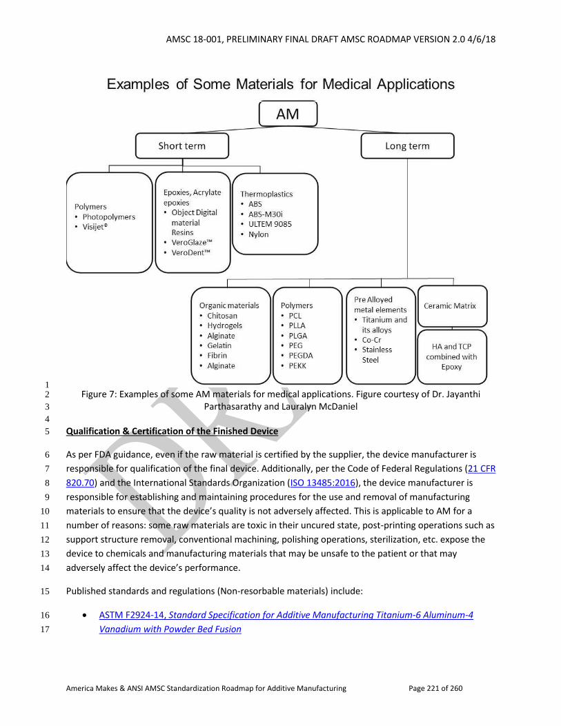
AMSC 18-001, PRELIMINARY FINAL DRAFT AMSC ROADMAP VERSION 2.0 4/6/18
America Makes & ANSI AMSC Standardization Roadmap for Additive Manufacturing Page 221 of 260
1 Figure 7: Examples of some AM materials for medical applications. Figure courtesy of Dr. Jayanthi 2
Parthasarathy and Lauralyn McDaniel 3
4
Qualification & Certification of the Finished Device 5
As per FDA guidance, even if the raw material is certified by the supplier, the device manufacturer is 6
responsible for qualification of the final device. Additionally, per the Code of Federal Regulations (21 CFR 7
820.70) and the International Standards Organization (ISO 13485:2016), the device manufacturer is 8
responsible for establishing and maintaining procedures for the use and removal of manufacturing 9
materials to ensure that the device’s quality is not adversely affected. This is applicable to AM for a 10
number of reasons: some raw materials are toxic in their uncured state, post-printing operations such as 11
support structure removal, conventional machining, polishing operations, sterilization, etc. expose the 12
device to chemicals and manufacturing materials that may be unsafe to the patient or that may 13
adversely affect the device’s performance. 14
Published standards and regulations (Non-resorbable materials) include: 15
ASTM F2924-14, Standard Specification for Additive Manufacturing Titanium-6 Aluminum-4 16
Vanadium with Powder Bed Fusion 17
AMSC 18-001, PRELIMINARY FINAL DRAFT AMSC ROADMAP VERSION 2.0 4/6/18
America Makes & ANSI AMSC Standardization Roadmap for Additive Manufacturing Page 222 of 260
ASTM F3001-14, Standard Specification for Additive Manufacturing Titanium-6 Aluminum-4 1
Vanadium ELI (Extra Low Interstitial) with Powder Bed Fusion 2
FDA 21 CFR 820.70, Production and process controls 3
ISO 13485:2016, Medical devices - Quality management systems - Requirements for regulatory 4
purposes 5
Standards in development include: 6
ASTM WK51329, New Specification for Additive Manufacturing Cobalt-28 Chromium-6 7
Molybdenum Alloy (UNS R30075) with Powder Bed Fusion1 8
ASTM WK53878, New Specification for Additive Manufacturing - Material Extrusion Based 9
Additive Manufacturing of Plastic Materials - Part 1: Feedstock materials 10
No gap exists. ISO 13485:2016 and 21 CFR 820 adequately describe the need to ensure that the final 11
finished device – including raw materials, pigments, contact materials, etc. – meets the design 12
requirements and does not cause harm to the patient. 13
14
Resorbable Materials 15
Some polymers, such as polycaprolactone, poly glycolic acid, and polylactic acid, may resorb when 16
implanted in the body, allowing for replacement of the device by body tissues over time. Degradation 17
kinetics of the device depends on the chemistry of the material, and structure and design of the scaffold. 18
Published standards include: 19
ASTM F1635-16, Standard Test Method for in vitro Degradation Testing of Hydrolytically 20
Degradable Polymer Resins and Fabricated Forms for Surgical Implants 21
ISO 10993-13:2010, Biological evaluation of medical devices -- Part 13: Identification and 22
quantification of degradation products from polymeric medical devices 23
ANSI/AAMI/ISO 10993-15:2000 (R2011), Biological evaluation of medical devices - Part 15: 24
Identification and quantification of degradation products from metals and alloys 25
ASTM F2902-16e1, Standard Guide for Assessment of Absorbable Polymeric Implants 26
ASTM F3160-16, Standard Guide for Metallurgical Characterization of Absorbable Metallic 27
Materials for Medical Implants 28
ISO/TR 37137:2014, Cardiovascular biological evaluation of medical devices -- Guidance for 29
absorbable implants 30
Standards in development include: 31
ISO/AWI TS 20721, Implants for surgery -- Standard guide to assessment of absorbable metallic 32
implants 33
ASTM WK52640, New Guide for In-Vitro Degradation Testing of Absorbable Metals 34
ISO/DTR 37137-2, Cardiovascular biological evaluation of medical devices -- Guidance for 35
absorbable implants -- Part 2: Standard guide for absorbable metals 36
AMSC 18-001, PRELIMINARY FINAL DRAFT AMSC ROADMAP VERSION 2.0 4/6/18
America Makes & ANSI AMSC Standardization Roadmap for Additive Manufacturing Page 223 of 260
ASTM WK61103, New Guide for Corrosion Fatigue Evaluation of Absorbable Metals 1
Gap QC12: Resorbable Materials. Testing of degradation of the new resorbable metals/polymers in 2
living tissues cannot be adequately achieved using existing standards. 3
R&D Needed: Yes, in terms of rate and amount of degradation for new polymers and resorbable metals. 4
Recommendation: Develop guidance on how to test the degradation of new resorbable 5
metals/polymers to support material selection for AM. 6
Priority: Medium 7
Status of Progress: Green 8
Update: None provided. 9
Organization: ASTM F4, ISO, ISO/TC 150, ISO/TC 194 10
Biocompatibility Testing Standards Available for Resorbable and Non-resorbable Materials 11
Existing standards include ANSI/AAMI/ISO 10993-1:2009 (R2013), Biological evaluation of medical 12
devices - Part 1: Evaluation and testing within a risk management process. This document supersedes 13
Blue Book Memorandum #G95-1 “Use of International Standard ISO-10993, Biological Evaluation of 14
Medical Devices Part 1: Evaluation and Testing, dated May 1, 1995. The FDA also issued Draft Guidance 15
on Technical Considerations of AM Medical Devices for comment on May 10, 2016. This includes FDA 16
recommendations for medical device submissions. 17
Material Control Data and Procedures 18
While no published standards or standards in development specific to AM have been identified for 19
medical applications, 21 CFR 820 provides the needed processes and data requirements. Specifically, § 20
820.65 – Traceability, § 820.140 - Handling , § 820.150 – Storage, and Subpart M--Records which 21
includes § 820.181 - Device master record, and § 820.186 - Quality system record details needs for 22
materials. 23
Gap QC13: Material Control Data and Procedures. There is a need for well-established material control 24
data and procedures. Materials are primarily manufactured through proprietary methods and, while 25
recommended handling practices exist for each company and each product, standard procedures or 26
standardized considerations are not available. 27
R&D Needed: Yes 28
Recommendation: A standard or specification describing a data set for material pedigree, 29
recommended testing, and handling procedures would simplify evaluation of material suitability. 30
Priority: Low 31
AMSC 18-001, PRELIMINARY FINAL DRAFT AMSC ROADMAP VERSION 2.0 4/6/18
America Makes & ANSI AMSC Standardization Roadmap for Additive Manufacturing Page 224 of 260
Status of Progress: Unknown 1
Update: No update provided. 2
Organization: Material providers, ASTM 3
Qualification and Control of Suppliers 4
A medical device company should have procedures in place to control their suppliers. Additionally, when 5
they audit their suppliers, they should ensure that the supplier has the proper controls in place to 6
control their sub-suppliers. Qualification and control of suppliers will align with other industry guidance 7
and standards such as: 8
FDA Quality System (QS) Regulation 9
(http://www.fda.gov/medicaldevices/deviceregulationandguidance/postmarketrequirements/q10
ualitysystemsregulations/ 11
Use of International Standard ANSI/AAMI/ISO 10993-1, Biological evaluation of medical devices - 12
Part 1:Evaluation and testing within a risk management process, Guidance for Industry and Food 13
and Drug Administration Staff (June 16, 2016) 14
http://www.fda.gov/downloads/medicaldevices/deviceregulationandguidance/guidancedocum15
ents/ucm348890.pdf 16
Patient Imaging Files and Segmentation 17
There are currently no standards for patient imaging files within a clinical environment, including the 18
methods from standard-of-care medical images to print ready files. 19
Process: Anatomical reconstruction is rarely done by the physicians themselves because it is: (a) time 20
consuming; (b) requires different technical skills than segmentation for visualization/quantification 21
purposes; and (c) uses a panoply of specialized software that is evolving frequently. Instead, a request to 22
print anatomy from a particular study is sent to expert staff at a “3D Printing Lab” (often an outgrowth 23
of a “3D Visualization Lab”). The physicians then review the 3D model and accept the print-ready file or 24
suggest revisions. Currently, no professional society certifies a technologist for 3D reconstruction or 3D 25
printing. 26
Consistency of data: Currently, most centers create print-ready-files in common, and often open, file 27
formats (STL, VRML, OBJ, X3D, etc.). These file formats were created without the intended purpose of 28
medical integration. As such, these formats lack the structured schema and metadata needed for the 29
clinical environment such as patient name, medical record number, institution of origin, etc. Centers 30
currently rely on complex file naming conventions and deep folder hierarchies to tie the files to 31
particular patient studies. These conventions are not appropriate for a clinical environment where 32
information needs to be readily queried for medical needs (e.g., surgical planning). 33
Published standards include: 34
AMSC 18-001, PRELIMINARY FINAL DRAFT AMSC ROADMAP VERSION 2.0 4/6/18
America Makes & ANSI AMSC Standardization Roadmap for Additive Manufacturing Page 225 of 260
HL7 Standard for CDA Release 2: Imaging Integration. This HL7 implementation guide describes 1
how the HL7 Version 3 Clinical Document Architecture (CDA) Release 2 is used to record information 2
for a Diagnostic Imaging Report. A Diagnostic Imaging Report contains a consulting specialist’s 3
interpretation of image data. It is intended to convey the interpretation to the referring (ordering) 4
physician and become part of the patient’s medical record. Note: This standard does not directly 5
interact with 3D reconstructions currently, but will likely play a role following DICOM integration. 6
Site: http://www.hl7.org/implement/standards/product_brief.cfm?product_id=13 7
DICOM, Digital Imaging and Communications in Medicine. DICOM is the international standard for 8
medical images and related information (ISO 12052:2017). It defines the formats for medical images 9
that can be exchanged with the data and quality necessary for clinical use. DICOM is implemented in 10
almost every radiology, cardiology imaging, and radiotherapy device (X-ray, CT, MRI, ultrasound, 11
etc.), and increasingly in devices in other medical domains such as ophthalmology and dentistry. 12
With tens of thousands of imaging devices in use, DICOM is one of the most widely deployed 13
healthcare messaging standards in the world. Note: The specification is the current standard for all 14
medical images captured in an institutional setting. 15
FDA Statements include: 16
On anatomical modeling: Di Prima M., Coburn J., Hwang D., Kelly J., Khairuzzaman A., Ricles L. 17
Additively manufactured medical products – the FDA perspective. 3D Printing in Medicine [Internet]. 18
2016 Jun 18 [cited 2016 May 22]; 2(1). Paraphrased: Anatomical models may sometimes be 19
considered a hard copy of a medical image. 20
On other direct-contact 3D printing: Technical Considerations for Additive Manufactured Devices: 21
Draft Guidance for Industry and Food and Drug Administration Staff. Food and Drug Administration; 22
2016 May. Report No. UCM499809. See the discussion under Identified Guidance Documents earlier 23
in the Q&C section of this roadmap. 24
Standards in development include: 25
DICOM. DICOM has activated a WG to integrate the needs of AM/3DP into the DICOM standard. 26
Incorporation of 3D segmentations/reconstructions into the DICOM specification will address many 27
clinical concerns such as 28
patient confidential information, 29
HIPAA compliance, 30
data maintenance/preservation, and 31
semi-automatic query. 32
Gap QC14: Segmentation. There are currently no standards for patient imaging files including the 33
methods from standard-of-care medical images to print ready files. There is no group or entity that 34
oversees segmentation within a clinical setting. RSNA has a special interest group that may set standards 35
for segmentation and/or 3D printing. DICOM WG 17 also is looking at this. 36
AMSC 18-001, PRELIMINARY FINAL DRAFT AMSC ROADMAP VERSION 2.0 4/6/18
America Makes & ANSI AMSC Standardization Roadmap for Additive Manufacturing Page 226 of 260
R&D Needed: No 1
Recommendation: There is a need to create an augmented file specification for the DICOM file format. 2
Incorporation of 3D files into the DICOM format will facilitate integration of 3D models into standard-of-3
care medical image databases present at all institutions. 3D models should include enough information 4
to facilitate standardized methods for validation. 5
Priority: Medium 6
Status of Progress: Green 7
Update: DICOM is addressing most of this. They will have public comment by the end of 2018, with a 8
target for the first update being made by the second quarter of 2019. 9
Organization: RSNA, DICOM, ASTM 10
Validation of Sterilization Processes 11
The issues of concern are: sterile barrier packaging; validation of the ability to clean, disinfect, and 12
sterilize products intended for subsequent processing; impact on final mechanical properties; and final 13
geometric fidelity. 14
The U.S. FDA regulates medical products and requires data to support claims of sterility or claims that a 15
device can be sufficiently sterilized for use. A list of standards recognized by the FDA in this respect 16
(which includes standards and guidance related to equipment, facilities, and sterilization-related 17
microbiological testing) is available online.31 See also the FDA Guidance Submission and Review of 18
Sterility Information in Premarket Notification (510(k)) Submissions for Devices Labeled as Sterile (issued 19
January 21, 2016). 20
Validation of sterilization processes: A number of published standards govern the validation of 21
sterilization processes used for medical devices, including ANSI/AAMI/ISO 11135:2014 (ethylene oxide 22
sterilization), the ANSI/AAMI/ISO 11137 series (radiation sterilization), the ANSI/AAMI/ISO 17665-23
1:2006 (R2013) series (moist heat sterilization), and ANSI/AAMI/ISO 20857:2010 (R2015) (dry heat 24
sterilization). For animal tissue-based products sterilized via glutaraldehyde, ANSI/AAMI/ISO 14160:2011 25
(R2016) applies and AAMI TIR37:2013 provides guidance for the sterilization of human tissue-based 26
products using radiation. See also the FDA’s Guidance for Industry: Current Good Tissue Practice (CGTP) 27
and Additional Requirements for Manufacturers of Human Cells, Tissues, and Cellular and Tissue-Based 28
Products (HCT/Ps). 29
For products requiring unique sterilization processes, ANSI/AAMI/ISO 14937:2009 (R2013) governs. For 30
medical devices that cannot be sterilized to a Sterility Assurance Level (SAL) of 10-6, ANSI/AAMI 31
31 Go to https://www.accessdata.fda.gov/scripts/cdrh/cfdocs/cfstandards/search.cfm and select “Sterility” in the Specialty Task Group Area. The search results identify some 141 standards with further information available by clicking on the title.
AMSC 18-001, PRELIMINARY FINAL DRAFT AMSC ROADMAP VERSION 2.0 4/6/18
America Makes & ANSI AMSC Standardization Roadmap for Additive Manufacturing Page 227 of 260
ST67:2011 (R2017) provides a risk management framework for justifying alternative SALs. For medical 1
devices produced via aseptic processing, the ANSI/AAMI/ISO 13408 series provides guidance. 2
Sterile barrier packaging: ANSI/AAMI/ISO 11607-1:2006 (R2010) and 11607-2:2006 (R2010) provide 3
requirements for packaging intended to maintain sterility, and ASTM standards provide packaging test 4
methods (D3078-02(2013), D4169-16, F1140/F1140M-13, F1608-16, F17-17, F1886/F1886M-16, F1929-5
15, F1980-16, F2054/F2054M-13, F2095-07(2013), F2096-11, F2097-16, F2203-13, F2217/F2217M-13, 6
F2228-13, F2250-13, F2251-13, F2252/F2252M-13e1, F2338-09(2013), F2391-05(2016), F2475-11, 7
F2638-12e1, F2825-10(2015), F88/F88M-15). 8
Validation of the ability to clean, disinfect, and sterilize products intended for subsequent processing: 9
ANSI/AAMI/ISO 17664:2017, Processing of health care products – Information to be provided by the medical 10
device manufacturer for the processing of medical devices (supersedes ST81) specifies what information a 11
medical device manufacturer must verify or validate for the cleaning, disinfection, and sterilization of 12
products intended to be sterilized by the product users (e.g., patients of healthcare providers). AAMI 13
TIR12:2010, Designing, testing and labeling reusable medical devices for reprocessing in health care 14
facilities: A guide for medical device manufacturers provides guidance on designing, testing and labeling 15
devices intended to be sterilized by healthcare facilities or other device users. 16
Impact of sterilization on mechanical properties of devices and geometric fidelity of devices: The 17
standards for validation listed above require evaluation of the effect of the sterilization process on the 18
final product. Other testing (e.g., biocompatibility testing) is also required on medical devices in their 19
final sterilized state. AAMI TIR 17:2008 provides information on materials compatibility with sterilization 20
processes. 21
Gap QC15: Sterilization of Anatomical Models. Anatomical models are frequently made in a healthcare 22
setting and their final use may differ from the initial intended use. For instance, a surgeon may 23
determine that a model patient education may be useful for reference in the operating room during the 24
surgical procedure. If the models enter the sterile field they would require sterilization and the effects of 25
sterilization on the geometric fidelity of the model should be assessed. If they are to come into contact 26
with the patient the effects of sterilization on the materials are especially important. While many 27
standards and industry best practices exist, the healthcare facilities may not have relevant experience. 28
R&D Needed: No. Procedures and protocols for determining appropriate materials, sterilization cycles, 29
and validation tests are already available but may not be implemented in healthcare settings. 30
Recommendation: Develop guides and best practices to help identify critical parameters and apply 31
existing standards in a clinical setting. 32
Priority: Low 33
Status of Progress: Unknown 34
Update: The SME medical group is working on a biocompatibility worksheet for use with both models 35
and surgical guides. This will not be a standard, but a guide of considerations. 36
AMSC 18-001, PRELIMINARY FINAL DRAFT AMSC ROADMAP VERSION 2.0 4/6/18
America Makes & ANSI AMSC Standardization Roadmap for Additive Manufacturing Page 228 of 260
Organization: R&D: OEMs. Guidance: AAMI, AOAC International, ASTM, ISO, PDA, USP, RSNA 3DP SIG. 1
Sterilization of Tissue Engineered Products 2
Reprocessing of reusable Additively Manufactured devices: Any device that is intended to be reused 3
should be reprocessed with a validated cycle per appropriate labelling as described in FDA Guidance on 4
“Reprocessing Medical Devices in Health Care Settings: Validation Methods and Labeling” (issued March 5
17, 2015). The considerations for additively manufactured devices are not expected to be different than 6
devices made in other ways. Rather, it is of paramount importance to assess the material stability and 7
limitations of the chosen AM production process. AAMI TIR12, AAMI TIR30:2011 (R2016), A compendium 8
of processes, materials, test methods, and acceptance criteria for cleaning reusable medical devices, and 9
ANSI/AAMI/ISO 17664:2017 (supersedes ST81) are also applicable. 10
Sterilization of tissue engineered products: There are some recognized standards and guidance in this 11
area (see above and see the work of ISO/TC 194/SC 1, Tissue-based products). Other standards exist 12
(e.g., ANSI/AAMI/ISO 13022:2012, Medical products containing viable human cells - Application of risk 13
management and requirements for processing practices), that have not been recognized by the FDA. 14
Another international standard which was not recognized by the FDA or adopted by the U.S. is ISO 15
18362:2016, Manufacture of cell-based health care products - Control of microbial risks during 16
processing. The development of additional standards in this area may require more research and testing 17
and greater clarity and guidance from regulators. 18
The FDA list of recognized standards provides known information about revisions of some of these 19
standards. An international technical specification, ISO/PRF TS 19330, Guidance on aspects of a risk-20
based approach to assuring sterility of terminally-sterilized, single-use health care products, is being 21
developed to provide a framework for evaluating alternatives for medical devices that cannot be 22
adequately sterilized via standard protocols. 23
Aseptic processing, or production under sterile conditions, of AM tissue-based products is another 24
method to ensure sterility of the final product. It is especially important when a construct contains cells 25
embedded in a printable, biocompatible substrate intended for implantation. FDA Guidance on Sterile 26
Drug Products Produced by Aseptic Processing – Current Good Manufacturing Practice provides an 27
overview of best practices. See also Gap D14. 28
NEW Gap QC16: Sterilization of Tissue Engineered Products. Tissue engineered products present a 29
particularly challenging circumstance for sterility assurance. While using a validated aseptic processing 30
protocol for tissue engineered products can maintain sterility, it is not always sufficient or practical. Risk 31
management standards can help decrease the risks of contamination with best practices but not provide 32
defined measures to ensure the sterility or assess contamination in a tissue engineered product. 33
R&D Needed: Maybe. A wide variety of aseptic processing and sterilization protocols exist for tissue 34
engineered products, however no standards have been published to address validation and testing of 35
these protocols in tissue engineered products. 36
AMSC 18-001, PRELIMINARY FINAL DRAFT AMSC ROADMAP VERSION 2.0 4/6/18
America Makes & ANSI AMSC Standardization Roadmap for Additive Manufacturing Page 229 of 260
Recommendation: Develop and validate standard methods of sterilizing and verifying the sterility of 1
tissue engineered products, especially those that can be applied in healthcare settings. 2
Priority: Medium 3
Organization: R&D: OEMs, FDA, BioFabUSA. Standards: AAMI, ISO, ASTM F04, ASTM F42, AATB. 4
2.3.3.4 Electronic and Electrical Products Industry 5
6
This industry focuses on producing electrified products for use in residential, commercial & industrial 7
applications including homes, retail/hospitality establishments, public spaces, offices and 8
factories/warehouses. The category can be subdivided into indoor and/or outdoor applications. 9
Furthermore, the category is sometimes further divided into home and/or professional applications. 10
Typically, such products are qualified and verified as part of a product certification to demonstrate 11
compliance with recognized product safety and performance standards. Also, since these products may 12
become permanent or semi-permanent elements of built structures, or structures themselves, they are 13
required to comply with installation and use requirements of relevant electrical or building codes and 14
regulations. 15
Use of Additive Manufacturing 16
AM has been in regular use to produce prototypes for physical examination, fit/function analysis and 17
test sample purposes. AM has also been used to produce tooling or jigs for product manufacturing 18
purposes. 19
More recently, there has been an industry shift toward an interest in using AM to produce parts of end-20
products. The Department of Energy has realized the advantages of AM for production of electronic and 21
electrical products. Multiple trade organizations and academic research institutions have begun to 22
examine the advantages of AM and are promoting its adoption for these applications. 23
Qualification and Certifications 24
Since electrical and electronics products are typically required to be qualified and certified to existing 25
product safety and performance standards, the use of an equivalent AM built component or full product 26
should also confirm to the practice of standards. Many of the applicable standards contain type-test 27
based evaluation criteria which allows parts to be qualified based on their physical & electrical 28
properties. Accordingly, type-testing of AM parts is an option. These standards also contain prescriptive 29
requirements based on historical data. The application of these prescriptive requirements could require 30
reconsideration of applicability to parts fabricated by AM. Certifications generally require ongoing 31
verification in production to ensure consistency between production parts and parts subject to 32
prescriptive and/or type-test qualification. Variations in parts due to different AM processes or parts 33
made using different equipment must be addressed. To address some of these variables, standards have 34
been developed for polymeric materials as described in the Identified Guidance Documents section of 35
this document. 36

AMSC 18-001, PRELIMINARY FINAL DRAFT AMSC ROADMAP VERSION 2.0 4/6/18
America Makes & ANSI AMSC Standardization Roadmap for Additive Manufacturing Page 230 of 260
Since products in this category many times also need to conform to installation requirements contained 1
in codes and regulations, consideration must be given to the application of AM parts in this context. 2
Such codes and regulations can focus on criteria such as fire resistance, smoke generation, structural 3
integrity and toxicity. As AM matures as a method of manufacturing general purpose electronic & 4
electrical products, there is a need to understand the possible ramifications on compliance with product 5
safety/performance standards and regulations. An understanding of differences between traditional 6
manufacturing techniques and AM regarding end-product performance is needed. 7
8
AMSC 18-001, PRELIMINARY FINAL DRAFT AMSC ROADMAP VERSION 2.0 4/6/18
America Makes & ANSI AMSC Standardization Roadmap for Additive Manufacturing Page 231 of 260
2.4 Nondestructive Evaluation (NDE) 1
2
2.4.1 Introduction (metals)32 3
4
Nondestructive Evaluation (NDE), also known as nondestructive testing (NDT) or nondestructive 5
inspection (NDI), is one of the engineering disciplines used to verify the integrity of high value 6
components.33 Task-specific NDE methods have been developed over many years. The most common 7
methods recognized and controlled by industrial standards are: X-ray, digital radiography, dye 8
penetrant, eddy current, magnetic particle, and ultrasonic testing. Adaptations of these methods are 9
also used in the medical industry for patient diagnoses. While both the industrial and medical industries 10
use these methods, the application of each is specifically designed for an intended purpose, material, 11
and characterization goal. 12
The U.S. military first controlled many of these standards used for the inspection of products provided 13
by the aerospace industry. During the military acquisition reform of the 1990s, changes shifted from the 14
military as owners to industry as owners. Two primary receiving organizations were ASTM International 15
and SAE International. These organizations continue to create, revise, and release NDE standards used 16
by U.S. industry to this day. 17
NDE methods to detect discontinuities and flaws are often cataloged by the character of the flaw and 18
the location within the part for which the inspection method is best suited. These flaw locations are 19
often referred to as: embedded, subsurface, surface, or surface breaking. Embedded flaw methods 20
include: X-ray, ultrasonic, eddy current, thermal imaging, and acoustic emission. Surface flaw detecting 21
methods include: penetrant, eddy current, acoustic emission, and ultrasonic. 22
NDE methods have differing outputs to display or record the testing results. For example, an X-ray is 23
viewed by an inspector who interprets what is recorded by the film or digital image. Ultrasonic pulse 24
echo results are viewed in real time using an A-scan presentation for real time inspection or an 25
amplitude response C-scan map created during the scanning of the part and subsequently interpreted 26
by the inspector. To the X-ray inspector, a pore or void indication may appear the same in a number of 27
manufacturing processes with a lower density than the surrounding material. In ultrasonic inspection 28
using the ultrasonic pulse echo, the inspector sees a reflection as a measurement of a returned signal 29
(echo) “amplitude” either on the A-scan or C-scan map (normally color coded amplitude bar). 30
32 The scope of this NDE section is generally focused on additive manufacturing of metal components. Other materials are discussed in section 2.4.6. 33 In this section, the term “component” is used to refer to the finished AM part or component being inspected. The term “phantom” refers to a calibration standard or other test specimen specifically designed and manufactured to demonstrate the capability of an inspection process (i.e., physical reference standard). When referring to both a component and a phantom, the term “object” is used.
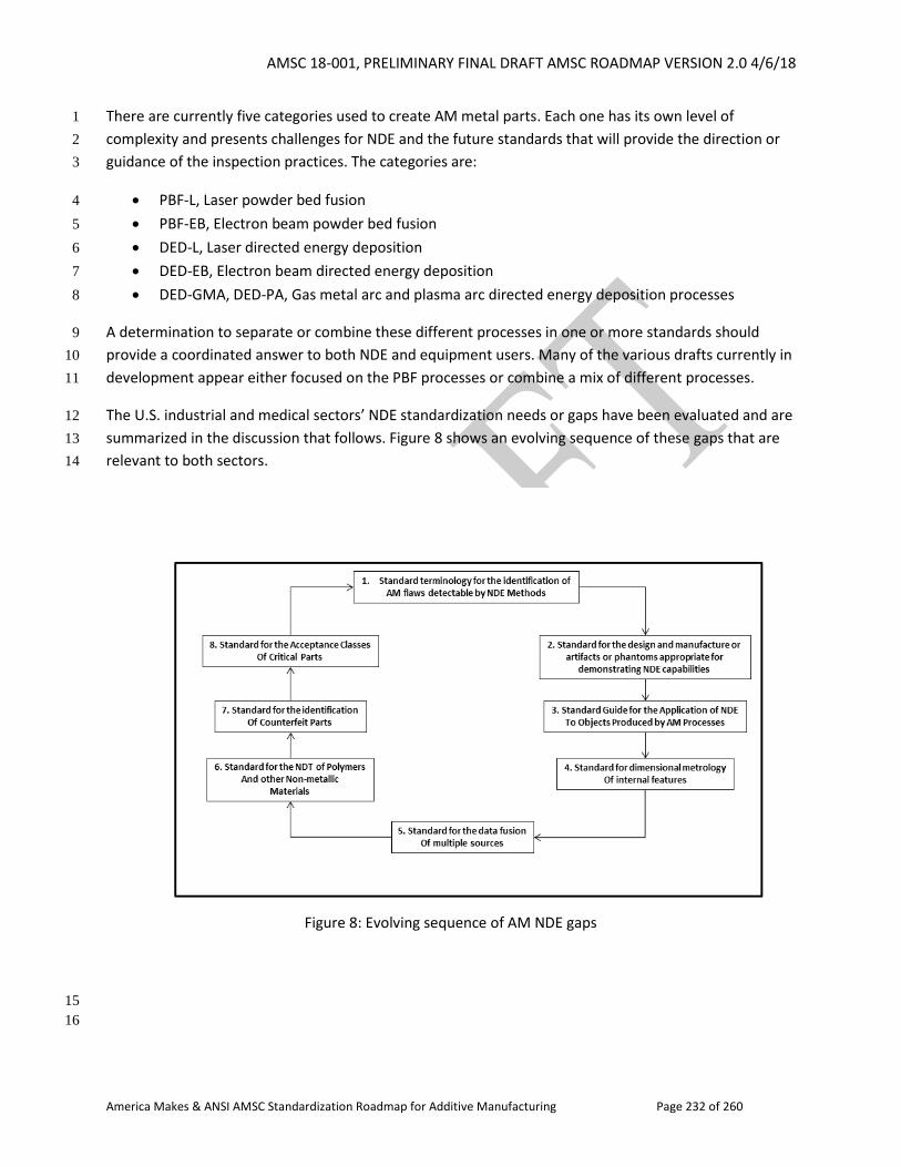
AMSC 18-001, PRELIMINARY FINAL DRAFT AMSC ROADMAP VERSION 2.0 4/6/18
America Makes & ANSI AMSC Standardization Roadmap for Additive Manufacturing Page 232 of 260
There are currently five categories used to create AM metal parts. Each one has its own level of 1
complexity and presents challenges for NDE and the future standards that will provide the direction or 2
guidance of the inspection practices. The categories are: 3
PBF-L, Laser powder bed fusion 4
PBF-EB, Electron beam powder bed fusion 5
DED-L, Laser directed energy deposition 6
DED-EB, Electron beam directed energy deposition 7
DED-GMA, DED-PA, Gas metal arc and plasma arc directed energy deposition processes 8
A determination to separate or combine these different processes in one or more standards should 9
provide a coordinated answer to both NDE and equipment users. Many of the various drafts currently in 10
development appear either focused on the PBF processes or combine a mix of different processes. 11
The U.S. industrial and medical sectors’ NDE standardization needs or gaps have been evaluated and are 12
summarized in the discussion that follows. Figure 8 shows an evolving sequence of these gaps that are 13
relevant to both sectors. 14
15
16
Figure 8: Evolving sequence of AM NDE gaps
AMSC 18-001, PRELIMINARY FINAL DRAFT AMSC ROADMAP VERSION 2.0 4/6/18
America Makes & ANSI AMSC Standardization Roadmap for Additive Manufacturing Page 233 of 260
2.4.2 Common Defects Catalog Using a Common Language for AM Fabricated 1
Parts 2
3
Terminology 4
Historically, flaw types, names, or classifications are associated with the generating process, e.g., 5
castings may contain “shrinkage” and welds may contain “incomplete penetration.” There are also 6
overlapping flaw types, for example, porosity. Additive manufacturing is another form of part 7
manufacturing with unique flaw types and classifications associated with the process. The need to 8
establish consensus flaw descriptions based on consensus terminology to accurately identify flaw types 9
and classifications is a gap that needs to be addressed. 10
Individual engineers and companies have discovered and termed additively manufactured flaws 11
stemming from their work in the AM process; however, there has been no industry-based standard with 12
the specific intent to address flaw types and names. Currently, flaw types, while described in literature 13
reports, have been restricted in definition to the content of the report. 14
As a new technology operating on principles many of which are foreign to conventional machining, 15
additive manufacturing is in need of industry agreement on definitions of specific terms to communicate 16
flaws and flaw types, ideas, and concepts, and to spur further innovation. In the absence of this common 17
agreement as to the precise meaning of words in their relative context, individuals and organizations 18
risk inevitable delays, misaligned objectives, and confusing outcomes. As an example, the words 19
“accuracy” and “precision” in common parlance are synonymous but, in metrology, the science of 20
measurement, they are not. Each describes a specific, unrelated attribute. 21
Published standards addressing terminology but not the individual flaw types or classifications needed 22
to accept or reject AM parts by nondestructive testing include: 23
ISO/ASTM 52900:2015, Additive Manufacturing - General Principles Terminology, developed by 24
ISO/TC 261 and ASTM F42 under their PSDO cooperation agreement 25
ISO/ASTM 52921:2013, Standard terminology for additive manufacturing - Coordinate systems 26
and test methodologies, developed by ASTM F42.01 and adopted via a fast-track procedure by 27
ISO/TC 261 under the PSDO cooperation agreement with ASTM F42 28
ASTM E1316-18a, Standard Terminology for Nondestructive Examinations, developed by ASTM 29
E07.92 30
Standards in development include: 31
ISO/ASTM DIS 52902, Additive manufacturing -- Test artefacts -- Standard guideline for 32
geometric capability assessment of additive manufacturing systems, addressing flaw types, 33
being developed jointly by ASTM F42 and ISO/TC 261 as JG 52 34
WK56649, New Guide for Standard Practice/Guide for Intentionally Seeding Flaws in Additively 35
Manufactured (AM) Parts being developed as JG 60 by ASTM F42 and ISO/TC 261 36
AMSC 18-001, PRELIMINARY FINAL DRAFT AMSC ROADMAP VERSION 2.0 4/6/18
America Makes & ANSI AMSC Standardization Roadmap for Additive Manufacturing Page 234 of 260
ASTM WK47031, New Guide for Nondestructive Testing of Additive Manufactured Metal Parts 1
Used in Aerospace Applications, which includes terminology, being developed in ASTM E07.10. 2
SAE AMS K, Non Destructive Methods and Processes Committee, coordinates with ASTM E07. 3
ASME's Boiler & Pressure Vessel Code group will be looking at NDE of a pressure vessel. They are 4
also looking at working with ASTM. 5
AWS D20.1 also includes a task group on inspection. 6
Gap NDE1: Terminology for the Identification of AM Flaws Detectable by NDE Methods. An industry 7
driven standard needs to be developed, with input from experts in metallurgy, NDE, and additive 8
manufacturing fabrication, to identify flaws or flaw concentrations with the potential to jeopardize an 9
AM object’s intended use. Many flaws have been identified but more effort is needed to agree on flaws 10
terminology, providing appropriate names and descriptions. 11
R&D Needed: No 12
Recommendation: Develop standardized terminology to identify and describe flaws, and typical 13
locations in a build. 14
Priority: High 15
Status of Progress: Green 16
Update: As noted in the text. 17
Organization: ASTM E07, ASTM F42/ISO TC 261, SAE AMS K, ASME BPVC, AWS D20, NIST 18
Defect Catalog and Equipment Standardization 19
Additively manufactured metal parts are made by sintering or melting powder, wire, or other feedstock 20
using two basic techniques referred to as powder bed fusion and directed energy deposition. These two 21
techniques employ different processing approaches but there are enough similarities to create a list of 22
flaws and defects, detectable by NDE examination methods, as tailored to the various equipment 23
approaches. 24
Currently, flaw types have been recognized by individual activities but lack formal review and 25
acceptance by the industry. Various U.S.-based committees have folded this subject into their purview 26
with little alignment. Calibration and phantoms are needed to standardize both industrial and medical 27
nondestructive equipment. 28
The ASTM work item WK47031 (under the ASTM E07 committee on NDT) will house, at a minimum, a 29
table with defects. Another work item (proceeding jointly as JG 60 under the ISO/TC 261 and ASTM F42 30
committees on Additive Manufacturing) is WK56649, New Guide for Standard Practice/Guide for 31
Intentionally Seeding Flaws in Additively Manufactured (AM) Parts, previously known as ASTM 32
WK49798. This work item is addressing “how to create defects” in AM processes for use in 33
nondestructive testing. 34
AMSC 18-001, PRELIMINARY FINAL DRAFT AMSC ROADMAP VERSION 2.0 4/6/18
America Makes & ANSI AMSC Standardization Roadmap for Additive Manufacturing Page 235 of 260
Nondestructive testing uses physical standards – specimens or phantoms – to ensure the equipment is 1
functioning at a specified level. These are in place for the inspection of well-established product forms. 2
The complexities of emerging 3D printed parts require new approaches and standards to set and 3
demonstrate equipment functionality. These new approaches and standards must have industry 4
acceptance as the basis for inspection techniques. 5
Gap NDE2: Standard for the Design and Manufacture of Artifacts or Phantoms Appropriate for 6
Demonstrating NDE Capability. No published standards exist for the design or manufacture of artifacts 7
or phantoms applicable to calibrating NDE equipment or demonstrating detection of naturally occurring 8
flaws (lack of fusion, porosity, etc.), or intentionally added features (watermarks, embedded geometrical 9
features, etc.). This standard should identify the naturally occurring flaws and intentional features. This 10
standard should also include recommendations regarding the use of existing subtractive machined 11
calibration standards or AM representative artifacts or phantoms. 12
R&D Needed: No. This may not need R&D but it will require obtaining the knowledge necessary to state 13
requirements and present supporting evidence, much like a round robin activity. 14
Recommendation: Complete work on WK56649, New Guide for Standard Practice/Guide for 15
Intentionally Seeding Flaws in Additively Manufactured (AM) Parts, now proceeding as ISO/TC 261/ASTM 16
F42 JG 60, to establish flaw types and conditions/parameters to recreate flaws using AM processes. 17
Priority: Medium 18
Status of Progress: Green 19
Update: As noted, ASTM WK56649 is in development. 20
Organization: ASTM F42/ISO TC 261 21
2.4.3 Test Methods or Best Practice Guides for NDE of AM Parts 22
23
Additive manufacturing technologies for the development, prototyping, and production of three- 24
dimensional objects are maturing rapidly. There are several different process categories of AM 25
technology being developed. Each category produces a unique set of material flaws that are different 26
from those produced by traditional manufacturing processes such as forging or casting. Due to the rapid 27
advancement of additive manufacturing, NDE practitioners new to the inspection of additively 28
manufactured objects are not aware of the differences in the process categories and the flaws they can 29
produce. NDE practitioners need to be made aware of the types of flaws each category can produce and 30
the appropriate NDE processes for discovering those flaws. 31
Published NDE standards include those under the jurisdiction of ASTM committee E07 and SAE AMS 32
committee K. These NDE process standards contain the details necessary to control the application of 33
each NDE method in general or to a specific application (e.g., castings, forgings, billet). Each NDE 34
method must have acceptance levels for accurate and repeatable results, which are typically referred to 35
as classes. The standard classes can be used in engineering analysis and provide quality criteria for 36
AMSC 18-001, PRELIMINARY FINAL DRAFT AMSC ROADMAP VERSION 2.0 4/6/18
America Makes & ANSI AMSC Standardization Roadmap for Additive Manufacturing Page 236 of 260
acceptability. By way of example, ultrasonic inspections for wrought products use flat bottom holes 1
defined by ASTM E127-15 and ASTM E428-08(2013) and implemented as acceptance classes in SAE 2
AMSSTD2154C and ASTM E2375-16. Similarly, X-ray inspection of titanium castings uses reference 3
radiographs to measure severity as defined in ASTM E1320-15. Acceptance standards may be imbedded 4
in the process standard or in a stand-alone standard such as MIL-STD-1907(4) NOT 3 for the penetrant 5
inspection of castings. Many of these existing standards will be directly applicable to objects produced 6
by AM without modification. Some modification or new standards may be needed for the complex 7
objects produced by AM that were not possible using conventional manufacturing techniques. 8
In terms of standards in development, ASTM E07.10 is working on ASTM WK47031, New Guide for 9
Nondestructive Testing of Additive Manufactured Metal Parts Used in Aerospace Applications. ISO/TC 10
261/JG 59 is creating a similar standard, ISO/ASTM NP 52905, Additive manufacturing – General 11
Principles – Non-destructive testing of additive manufactured products. This is a joint project between 12
ISO/TC 261 and ASTM Committee F42. Guidance documents such as these will provide the NDE industry 13
a starting point for designing inspection processes for additively manufactured objects. The knowledge 14
generated with the creation of these documents will establish a baseline for determining when existing 15
NDE standards can be used and where new ones specific to additive manufacturing must be developed. 16
Current inspection results indicate that non-complex objects can be inspected using existing standards. 17
Post-processing of the objects is generally required and can be performed to currently released 18
standards. 19
Gap NDE3: Standard Guide for the Application of NDE to Objects Produced by AM Processes. There is a 20
need for an industry-driven standard led by nondestructive testing experts and supported by the 21
additive manufacturing community to assess current inspection practices and provide an introduction to 22
nondestructive testing and inspection requirements. 23
R&D Needed: Yes. Round robin testing is underway in ASTM E07. A future need will be a precision and 24
bias statement to generate standard test methods to accept/reject AM parts and in procurement of AM 25
parts. 26
Recommendation: Complete work on ASTM WK47031, New Guide for Nondestructive Testing of 27
Additive Manufactured Metal Parts Used in Aerospace Applications and ISO/ASTM NP 52905, Additive 28
manufacturing – General Principles – Non-destructive testing of additive manufactured products, proceeding as 29
ISO/TC 261/JG 59. 30
Priority: High 31
Status of Progress: Green 32
Update: ASTM WK47031 and ISO/TC 261/JG 59 are in development. ASME is also looking at NDE vis a vis 33
its boiler and pressure vessel code. 34
Organization: ASTM E07, ASTM F42/ISO TC 261, ASME, NIST 35
AMSC 18-001, PRELIMINARY FINAL DRAFT AMSC ROADMAP VERSION 2.0 4/6/18
America Makes & ANSI AMSC Standardization Roadmap for Additive Manufacturing Page 237 of 260
2.4.4 Dimensional Metrology of Internal Features 1
2
The additive manufacturing process presents unique challenges in dimensional metrology. There are 3
many aspects when determining the quality and form, especially internal features, of the parts produced 4
via the AM process. Destructive measurement methods produce results that differ from those 5
generated by nondestructive methods. Therefore, dimensional control is a challenge when measuring 6
internal features of certain parts created in the AM process. Internal structures, tolerances and their 7
limits, and material characterization of complex 3D structures cannot be measured with the standard 8
metrological methods available today. 9
Among the leading NDT technologies in the AM world are X-ray computed tomography (CT), which can 10
measure internal features of a part after fabrication, and structured light, which can measure external 11
features either during or after fabrication. CT technology provides important measurements such as wall 12
thickness, porosity analysis, material structural analysis, and, most importantly, complex internal hollow 13
structures that are otherwise impossible to measure. 14
Another important aspect is determination of the type of NDT process to be applied, knowing the 15
surface roughness measurement. Surface roughness may meet the print specifications but there can be 16
abnormalities (uneven surface, etc.) from the build. Further, the type of AM process to be used, and 17
what parts need to be manufactured, are key design aspects. All these factors must be kept in mind 18
when applying measurement techniques to AM parts. 19
Published CT or related standards include: 20
ASTM E1570-11, Standard Practice for Computed Tomographic (CT) Examination 21
ISO 15530-3:2011, Geometrical product specifications (GPS) - Coordinate measuring machines 22
(CMM): Technique for determining the uncertainty of measurement - Part 3: Use of calibrated 23
workpieces or measurement standards 24
A German standard VDI/VDE 2630 Blatt 1.4, Computed tomography in dimensional metrology: 25
measurement procedure and comparability 26
AM-related standards in development outside of ASTM Subcommittee E07.01 on Radiology (X and 27
Gamma) Method include: 28
ASTM WK47031, New Guide for Nondestructive Testing of Metal Aerospace Additive 29
Manufactured Parts After Build, by ASTM E07.10 on Specialized NDT Methods 30
ASTM E07.01 has started work on two draft practices on: 31
CT metrology based on German VDI standards (WK61974, New Practice for Standard Practice for 32
characterization of computed tomography systems for dimensional measurement), and 33
Qualification of CT for inspection for volumetric flaws, cracks and defects using cone beam CT 34
(WK61161, New Practice for Volumetric Computed Tomographic (CT) Examination Using Digital 35
Detector Arrays). 36
AMSC 18-001, PRELIMINARY FINAL DRAFT AMSC ROADMAP VERSION 2.0 4/6/18
America Makes & ANSI AMSC Standardization Roadmap for Additive Manufacturing Page 238 of 260
In addition, a current E07.01 standard for evaluating CT system performance is undergoing revision 1
(WK61162, Revision of E1695 - 95(2013) Standard Test Method for Measurement of Computed 2
Tomography (CT) System Performance). 3
It should be noted that, while the above CT standards address internal metrology directly (WK61161 and 4
WK61974) or indirectly (E1570 and E1695), providing a basis for dimensional metrology of internal 5
features in AM parts, none are written specifically for AM parts. 6
Research on the topic of dimensional metrology of internal features of AM parts has been undertaken 7
by, among others, NASA, the Army, Air Force, and Navy. A significant study is “Nondestructive 8
Evaluation of Additive Manufacturing” by NASA. Other texts include: 9
Higginbotham, K. Additive Manufacturing & NDE Tasks Applicable to SLS. MSFC/Advanced 10
Development Office, April 3, 2014. 11
Kjelgaard, C. The new meaning of additive value. Aerospace America, 20-22, November 2013. 12
Ghidini, T. European Space Agency Perspective on Additive Manufacturing (AM). 3D Printing & 13
Additive Manufacturing – Industrial Applications, Global Summit, London, UK, November 2011. 14
Research has also been undertaken on the topic of CT measurement of porosity distribution in AM 15
fatigue samples: 16
17
Brandão, Gumpingera, Gschweitlb, Seyfertc, Hofbauer, Ghidini, Fatigue Properties of Additively 18
Manufactured AlSi10Mg – Surface Treatment Effect, Procedia Structural Integrity, 7, 58-66 19
(2017). 20
Gap NDE4: Dimensional Metrology of Internal Features. The utility of existing and draft CT standards 21
are needed for the dimensional measurement of AM internal features. 22
R&D Needed: Yes 23
Recommendation: ASTM E07 should address the applicability of current and draft CT standards (E1570, 24
E1695, WK61161, and WK61974) for measurement of internal features in additive manufactured parts, 25
especially parts with complex geometry, internal features, and/or embedded features. Current CT 26
metrology state-of-the-art needs to be tailored to evolving AM part inspection requirements. See also 27
Gap D26, Measurement of AM Features/Verifying the designs of features such as lattices, etc. 28
Priority: Medium 29
Status of Progress: Green 30
Update: As noted in the text. 31
Organization: ASTM 32
AMSC 18-001, PRELIMINARY FINAL DRAFT AMSC ROADMAP VERSION 2.0 4/6/18
America Makes & ANSI AMSC Standardization Roadmap for Additive Manufacturing Page 239 of 260
2.4.5 Data Fusion 1
2
Data fusion in the NDT metrology world is defined as applying more than one NDT technique to provide 3
additional, complementary, or redundant information that can conform with the result. Data fusion 4
provides the ability to measure the same location from different viewpoints. This is needed because of 5
the complex geometry that might exist in AM parts. Setting this process up is not easy as it might require 6
a robotic-based or automated positioning system. One example of this methodology can be applying the 7
eddy current method to check surface detection, but then using ultrasonic methods to get volumetric 8
information. Combining the data sets from both will provide a simple, unified interpretation of results. 9
Data fusion also is used in a scenario where model-based inspection techniques for AM rely on the 10
combination of a number of different models and data sets to derive meaningful interpretation and 11
utility of the inspection results. NDE data plays an important role in product acceptance/rejection, 12
validation of simulation/predictive models, process improvement, and potentially process control. 13
Models include: the original part or feature model (either a surface or solid model); the build model to 14
include support structure, fixture, or base features (hybrid parts); and models or data sets associated 15
with NDE or metrology scans such as CT reconstructions and 3D and 2D feature maps. The orientation of 16
these data sets in a common frame of reference is critical to interpreting the differences and 17
relationship of the features. In one example, an as-built model calculated from a CT reconstruction may 18
be compared to an original part model to determine geometric fidelity, or how to orient the as-built part 19
to find the finished product within the near net shaped deposit. In another example, the comparison of 20
the finished part model may be compared with the as-deposited model and the location of near surface 21
defects, to ensure adequate machining allowance is provided to remove the defects identified within an 22
NDE-generated data set. Thermomechanical simulation may be compared with as-built data sets, to 23
derive the character or location of distortion or feature resolution from form metrology methods. 24
No published standards or standards in development have been identified. 25
Gap NDE5: Data Fusion. Since multiple sources and results are combined in data fusion, there is a 26
possible issue of a non-linear data combination that can produce results that can be influenced by the 27
user. Additionally, data fusion may employ statistical techniques that can also introduce some ambiguity 28
in the results. While likely more accurate than non-data fusion techniques, introduction of multiple 29
variables can be problematic. Data fusion techniques also require a certain level of expertise by the user 30
and therefore there might be a need for user certification. 31
R&D Needed: No 32
Recommendation: The following are needed to address the gap: 33
Specific industry standards are needed for data fusion in AM NDT techniques 34
Expert education, training, and certification for AM data fusion in NDT 35
Priority: Medium 36
AMSC 18-001, PRELIMINARY FINAL DRAFT AMSC ROADMAP VERSION 2.0 4/6/18
America Makes & ANSI AMSC Standardization Roadmap for Additive Manufacturing Page 240 of 260
Status of Progress: Unknown 1
Update: None available 2
Organization: ASTM 3
2.4.6 NDE of Polymers and Other Non-Metallic Materials 4
5
For polymers, the most common NDE methods recognized and controlled by industrial standards are 6
surface and embedded: acoustic emission, computed tomography, leak testing, radiography, 7
shearography, spectroscopy, strain measurement, thermography, ultrasonic testing, and visual testing. 8
ASTM E2533-17e1, Standard Guide for Nondestructive Testing of Polymer Matrix Composites Used in 9
Aerospace Applications, is valid for NDE of polymer matrix composites (PMCs), and therefore has 10
peripheral relevance to NDE of plastics used in AM (ABS, PLA, nylon, PEKK, Ultem). That said, AM plastic 11
parts are expected to have similar characteristics to PMCs, therefore, the same or similar NDE 12
techniques might be applicable. 13
There are currently five categories used to create AM polymer parts. The categories are: 14
Powder bed fusion 15
Material extrusion 16
Vat polymerization 17
Material jetting 18
Sheet lamination 19
20
NEW Gap NDE6: NDE of Polymers and Other Non-Metallic Materials. No published or in development 21
standards or specifications have been identified for NDE of polymers and other non-metallic materials. 22
R&D Needed: Yes. Research who uses AM Fused Filaments or pellets with PAI/Torlon and/or carbon 23
fiber reinforced filaments with a high degree of fiber loading to see what they are anticipating for 24
testing requirements for NDE for strength or structural qualities. 25
Recommendation: There is a need for an industry-driven standard led by nondestructive testing experts 26
and supported by the additive manufacturing community to assess current inspection practices and 27
provide an introduction to nondestructive testing and inspection requirements for structural or load 28
bearing polymers and other non-metallic materials. Use ASTM E2533-17e1 as a guideline when 29
applicable. 30
Priority: Low 31
Organization: ASTM F42/ISO TC 261, ASTM E07, ASTM D20 32
2.4.7 NDE of Counterfeit AM Parts 33
34
AMSC 18-001, PRELIMINARY FINAL DRAFT AMSC ROADMAP VERSION 2.0 4/6/18
America Makes & ANSI AMSC Standardization Roadmap for Additive Manufacturing Page 241 of 260
To protect against counterfeit 3D parts, anti-counterfeiting methods are being developed for 1
components produced via AM. Nondestructive evaluation methods may be used in conjunction with 2
some anti-counterfeiting methods to verify product authenticity. AM-specific considerations for aligning 3
NDE with anti-counterfeiting include: 4
Using as-manufactured NDE data, especially for polymers, to establish a standard for later field 5
validation 6
Incorporate and keep current cybersecurity practices to manage the creation and storage of 7
NDE data used for anti-counterfeiting verification 8
Simple NDE methods that are compatible with decentralized inventory management enabled by 9
the AM manufacturing model. 10
Methods to detect covert markings 11
Best practices in other industries recognize the interplay between security and quality, address the 12
advantages of providing authentication options at multiple points in the supply chain and encourage 13
scalable approaches that make it difficult to counterfeit the anti-counterfeiting measures.34 An 14
Aerospace Industries Association (AIA) report covering counterfeiting recommended that standards in 15
the area of mechanical parts and materials be established.35 16
Potentially relevant published standards for general industry include: 17
SAE AS 5553B-2016, Counterfeit Electrical, Electronic, and Electromechanical (EEE) Parts; 18
Avoidance, Detection, Mitigation, and Disposition 19
SAE AS 6174A-2014 (SAE AS6174A-2014), Counterfeit Materiel; Assuring Acquisition of Authentic 20
and Conforming Materiel 21
Potentially relevant standards in development for general industry include: 22
ISO/DIS 22380, Security and resilience -- Authenticity, integrity and trust for products and 23
documents -- General principles for product fraud risk and countermeasures 24
NEW Gap NDE7: NDE of Counterfeit AM Parts. No published or in development NDE standards for 25
methods used to verify anti-counterfeiting methods. 26
R&D Needed: Not at this time. Future R&D may be needed if an anti-counterfeiting method is 27
developed which cannot be verified by existing NDE methods or standards. 28
Recommendation: Develop NDE methods and standards for anti-counterfeiting that are not addressed 29
by existing methods or standards. 30
34 See for example Best Practices in the Fight Against Global Counterfeiting, published by ANSI in 2011. 35 See A Special Report Counterfeit Parts; Increasing Awareness and Developing Countermeasures, published by AIA in March 2011.
AMSC 18-001, PRELIMINARY FINAL DRAFT AMSC ROADMAP VERSION 2.0 4/6/18
America Makes & ANSI AMSC Standardization Roadmap for Additive Manufacturing Page 242 of 260
Priority: Low 1
Organization: ASTM F42/ISO TC 261, ASTM E07, SAE AMS-AM 2
3
2.4.8 NDE Acceptance Criteria for Fracture Critical AM Parts 4
5
In general, fracture critical AM hardware requires comprehensive volumetric and surface NDE to ensure 6
the hardware is acceptable for use. To quantify the risks associated with parts that must demonstrate 7
damage tolerance, it is incumbent upon the structural assessment community to define critical initial 8
flaw sizes (CIFS) for the part to define the objectives of the NDE. Knowledge of the CIFS will allow the 9
NDE and fracture control community to evaluate risks and communicate meaningful recommendations 10
regarding the acceptability of the risk. 11
In the application of NDE, the types of defects that are relevant to the AM process must be considered. 12
There are longstanding NDE standard defect classes for welds and castings. The defects characteristic to 13
these processes may not be applicable to the AM process. This implies that until an accepted PBF-L 14
defect catalog and associated NDE detection limits for PBF-L defects are established, the NDE techniques 15
and acceptance criteria may remain part-specific point designs. 16
NEW Gap NDE8: NDE Acceptance Criteria for Fracture Critical AM Parts. There is a need for an industry 17
standard that establishes NDE acceptance classes for fracture critical AM parts. 18
R&D Needed: Yes. Well-characterized samples should be fabricated with controlled loadings of 19
technologically important AM defects in order to conduct effect-of-defect studies. 20
Recommendation: Develop an industry standard that establishes different degrees of flaw 21
concentrations for quality acceptance. Fabricate effect-of-defect samples with the appropriate level of 22
fidelity, i.e., sufficient similarity between the defect state in sacrificial samples (for example, ASTM E8 23
compliant dogbones) with natural flaws in actual production parts. 24
Priority: Medium 25
Organization: ASTM F42 / ISO TC 261 JG 59, ASTM E07, ASTM E08 on Fracture and Fatigue 26
27
AMSC 18-001, PRELIMINARY FINAL DRAFT AMSC ROADMAP VERSION 2.0 4/6/18
America Makes & ANSI AMSC Standardization Roadmap for Additive Manufacturing Page 243 of 260
1
2.5 Maintenance and Repair 2
2.5.1 Introduction 3
Maintenance 4
For purposes of this discussion, “maintenance” is defined as encompassing maintenance of AM 5
machines; condition based maintenance (CBM)36 as it relates to the use of metal and polymer AM 6
processes and equipment; level of repair analysis (LORA)37 and reliability centered maintenance (RCM)38 7
analysis of AM parts, tools, and equipment; training of maintenance personnel; and maintenance 8
inspection of AM machines. 9
Additive Repair 10
Additive repair processes apply exclusively to metal components and refer to processes used to add or 11
build up material onto a substrate. The repaired surface(s) and component are then returned to the as-12
designed condition by subtractive manufacturing methods. Additive repair processes in current use 13
include blown metal powder systems and hybrid (additive + subtractive) systems. For some applications, 14
metal cold spray processes (high pressure cold spray systems) can be used to add metal to an existing 15
surface for structural purposes. Other aspect of additive repair include, requirements for metal powder 16
used for additive repair, surface preparation requirements, qualification and certification of the repair 17
process, and inspection of repairs performed with AM technology. There are currently no materials, 18
processes or equipment that are used to additively repair polymer AM parts. 19
Tools and Tooling 20
36 Conditioned Based Maintenance: Performing Maintenance based on Need (i.e., based on the Condition or Health of a component or system rather than on a periodic or scheduled basis). Source: ARP6461, Guidelines for Implementation of Structural Health Monitoring on Fixed Wing Aircraft. The purpose of Condition Based Maintenance (CBM) is to reduce the maintenance and life-cycle costs by using a proactive strategy of performing maintenance based on evidence of need. That is contrasted with Interval Based Maintenance, where the action is performed at a set interval (measured by time, mileage or some other metric). Source: SAE TAHB0009, Reliability Program Handbook 37 Level of Repair Analysis (LORA): An analytical methodology used to assist in developing maintenance concepts, influencing design, and establishing the maintenance level at which components will be replaced, repaired, or discarded based on economic/noneconomic constraints and operational readiness requirements. Source: AS1390, Level of Repair Analysis (LORA) 38 Reliability Centered Maintenance (RCM) is a logical, structured framework that leverages reliability assessment activities to determine the optimum mix of applicable and effective maintenance activities needed to sustain the desired level of operational reliability of products/systems while ensuring their safe and economical operation and support. Source: SAE TAHB0009, Reliability Program Handbook
AMSC 18-001, PRELIMINARY FINAL DRAFT AMSC ROADMAP VERSION 2.0 4/6/18
America Makes & ANSI AMSC Standardization Roadmap for Additive Manufacturing Page 244 of 260
As more fully described below, tools and tooling refer to creation or repair of those artifacts needed to 1
execute a parts repair and/or remanufacture for the purposes of scheduled maintenance or general 2
upgrade/overhaul. Tools and tooling as applied here may also include molds and dies that are 3
manufactured using AM processes. Tools refer to those parts and assemblies designed and 4
manufactured by AM processes and used to support the manufacture and/or repair of industrial or 5
aerospace equipment and systems. Tooling refers to those parts that are designed and manufactured by 6
AM processes and used to make the end use parts that become part of the aircraft itself (or the 7
industrial or aerospace equipment and systems). 8
2.5.2 Maintenance and Sustainment of Machines 9
10
Manufacturers have prescribed methods for maintenance of their particular additive machines. The 11
intent of focusing on this area is not to circumvent manufacturer-recommended machine maintenance 12
practices, but to establish boundaries for standardization of the various maintenance activities that may 13
be unique to AM machines whether the machines are used to produce metal AM or polymer AM parts. 14
These may include for example: 15
Facility requirements that will provide for future maintenance of the AM machines including but 16
not limited to: electrical power supply requirements; power conditioning requirements; standby 17
power requirements or recommendations; water availability and quality or filtration 18
requirements; structural requirements for supporting the AM machine; lighting; limits on 19
temperature and humidity where the AM machine is installed; and distance from machine to 20
wall of room (required to support maintenance, air flow, people, etc.) 21
Safety overviews 22
Skill set required to perform maintenance on AM machines 23
Training of maintenance personnel 24
Documentation of AM maintenance programs 25
Hazardous materials related to AM machines 26
Software maintenance and cybersecurity related to AM machines 27
Gap M1: AM Analyses in RCM and CBM. With respect to maintenance and sustainment of AM 28
machines, standards for AM analyses in Reliability Centered Maintenance (RCM) and Conditioned Based 29
Maintenance (CBM+) are needed. 30
R&D Needed: No 31
Recommendation: Update SAE JA 1012-2011, a guide to provide analytics for AM trade-offs in RCM and 32
CBM+. 33
AMSC 18-001, PRELIMINARY FINAL DRAFT AMSC ROADMAP VERSION 2.0 4/6/18
America Makes & ANSI AMSC Standardization Roadmap for Additive Manufacturing Page 245 of 260
Priority: Medium 1
Status of Progress: Not Started 2
Update: SAE G-11M, Maintainability, Supportability and Logistics Committee, will consider inclusion of 3
analytics for AM trade-offs in the next update of JA1012_201108. 4
Organization: SAE, ISO, ASTM 5
See also Gap PC2 on machine calibration and preventative maintenance, and Gap PC14 on 6
environmental health and safety issues and protection of AM machine operators. 7
2.5.3 Standard Repair Procedures 8
9
AM technology for sustainment-related repairs can provide faster solutions to obsolescence and 10
diminishing sources of supply due to the large quantity of systems, subsystems, parts and tooling that 11
are no longer available or manufactured, or where no data exists. It has the potential to provide relief to 12
weapon systems support required in the field by providing on-site repair capability. Materials are a 13
factor since there are several types of powder metal materials that can be used. Different powders can 14
be engineered for each application, operational load spectrum, and standards should be established for 15
the AM repair industry. (See Gap PM7.) Other factors to be addressed in the use of AM processes to 16
repair end use parts or tooling include: 17
Qualification and certification of the repair, including inspection of repairs (See also Q&C section 18
of this roadmap.) 19
Standard cleaning, and handling to prepare surfaces for adding material 20
The urgency of the maintenance required, e.g., requiring creation of a missing tool using 21
additive technology 22
Trade space related to different levels of repair and methods for accomplishing similar repairs 23
using traditional technologies and AM, e.g., relating to Life Cycle Cost (LCC)39 Analysis, LORA, and 24
RCM40 25
39 Life Cycle Cost (LCC): Life Cycle Cost consists of research and development (R&D) costs, investment costs, operating and support (O&S) costs, and disposal costs over the entire life cycle of a product. Source: AS1390, Level of Repair Analysis (LORA) 40 “Trade space” refers to an aspect of analysis where variables are introduced to allow for alternate solutions to be developed and compared. Amending doctrine on LCC Analysis, LORA, and RCM will allow for new variables to be analyzed.
AMSC 18-001, PRELIMINARY FINAL DRAFT AMSC ROADMAP VERSION 2.0 4/6/18
America Makes & ANSI AMSC Standardization Roadmap for Additive Manufacturing Page 246 of 260
Reverse engineering of legacy parts (2D drawing conversion to 3D model) for AM tool path 1
generation; dimensional measurement during AM repair development and post inspection; and 2
load/stress analysis substantiation. 3
Development of test plans and specifications to qualify an organization’s use of an additive 4
repair process, including acceptance criteria. 5
Adaptation of existing standards requirements into the development of qualification test plans 6
and specifications. 7
Existing standards that relate to this topic include: 8
DoD: MIL-STD-3049(1) on DED metal remanufacture/restoration 9
ISO/TC 44 (welding): ISO 15609-1:2004, Specification and qualification of welding procedures for 10
metallic materials - Welding procedure specification - Part 1: Arc welding 11
American Welding Society (AWS) D17.1/D17.1M:2010-AMD1, Specification for Fusion Welding 12
for Aerospace Applications - AMD 13
AWS B2.1/B2.1M:2014, Specification for Welding Procedure and Performance Qualification 14
SAE AMS-B, Finishes, Processes and Fluids: SAE AMS2680C-2001, Electron-Beam Welding for 15
Fatigue Critical Applications (Reaffirmed: March 2010) which is currently under revision 16
ASME B107 series of standards 17
Metallic Materials Properties Development and Standardization (MMPDS), April 2011 18
Standards in development include: AWS D20.1, Specification for Fabrication of Metal Components using 19
Additive Manufacturing. 20
NEW GAP M9: Laser Based Additive Repair. Current standards do not specifically address the use of 21
laser based systems (metal powder or wire feedstock) to additively repair parts or tools. 22
R&D Needed: No 23
Recommendation: Ensure that laser based additive repair processes are included in AWS D20.1 24
Priority: Low 25
Organization: AWS 26
27
Gap M3: AM Level of Repair Analysis. Standards for AM LORA are needed. In performing a repair versus 28
discard analysis, the use of AM can change the LORA decision due to shifts in factors relating to logistics 29
AMSC 18-001, PRELIMINARY FINAL DRAFT AMSC ROADMAP VERSION 2.0 4/6/18
America Makes & ANSI AMSC Standardization Roadmap for Additive Manufacturing Page 247 of 260
delay time, spares availability, cost of spares, etc. Trade space would address reduction of time and 1
increase in skill set (e.g., for qualified printer operators). 2
R&D Needed: No 3
Recommendation: Update SAE AS 1390-2014, Level of Repair Analysis (LORA), to include impact of AM 4
on trade space of repairs. 5
Priority: Medium 6
Status of Progress: Green 7
Update: SAE’s LCLS (Life Cycle Logistics Supportability) Committee plans to include AM in the upcoming 8
revision of AS1390. Although the LCLS Committee has not opened a Work in Progress for AS1390, a 9
team is working on revisions and has agreed to include AM. The G-11M is in the process of reorganizing 10
but the chair has the AMSC requests on his radar. In addition, AMS2680C is currently under revision. 11
Organization: SAE LCLS, SAE AMS-B, ISO, ASTM 12
2.5.4 Standard Technical Inspection Processes 13
Physical inspection of parts and tools/tooling requires a standardized assessment of defects, including 14
corrosion, abrasion/wear, cracks/fractures, and the suitability of additive manufacturing technologies as 15
a corrective repair action for such defects. Standard inspection procedures provide guidance to 16
maintainers to schedule preventative maintenance tasks, prioritize part or tooling defect cases, assess 17
risks, determine corrective action measures, and determine repair vs. remanufacture from a technical 18
feasibility and cost standpoint. Standard inspection procedures do not adequately consider the viability 19
of additive manufacturing technologies for preventative and corrective maintenance actions. Inspection 20
tools and procedures include: 21
Visual inspection 22
Magnetic particle inspection 23
Fluorescent and liquid penetrant inspection 24
Computed tomography (CT) scan 25
Radiography/X-ray inspection 26
Acoustic emission 27
Model-based inspection (e.g., 3D scanning) covered more in the next section 28
Ultrasonic inspection 29
Preventative maintenance scheduling 30
AMSC 18-001, PRELIMINARY FINAL DRAFT AMSC ROADMAP VERSION 2.0 4/6/18
America Makes & ANSI AMSC Standardization Roadmap for Additive Manufacturing Page 248 of 260
Risk assessment 1
Part condition categorization 2
Existing standards that relate to this topic include: 3
4
SAE JA 1011-2009, Evaluation Criteria for Reliability-Centered Maintenance (RCM) Processes 5
SAE JA 1012-2011, A Guide to the Reliability-Centered Maintenance (RCM) Standard 6
ASTM E1742/E1742M-12, Standard Practice for Radiographic Examination 7
ASTM E1444/E1444M-16e1, Standard Practice for Magnetic Particle Testing 8
SAE AS 1390-2014, Level of Repair Analysis (LORA) 9
No standards in development have been identified. 10
Gap M4: Physical Inspection of Parts Repaired Using AM. A standard Inspection process for component 11
or tooling defects is needed to consider additive manufacturing technologies as potential solutions for 12
preventative and corrective maintenance actions. 13
R&D Needed: No 14
Recommendation: Update SAE JA1011/1012 to include an inspection process for additive 15
manufacturing repairs. 16
Priority: Medium 17
Status of Progress: Not Started 18
Update: SAE G-11M, Maintainability, Supportability and Logistics Committee, will consider inclusion of 19
an inspection process for AM repairs in the next update of JA1011_200908 and JA1012_201108. 20
Organization: SAE, ISO/ASTM 21
2.5.5 Model-Based Inspection 22
Model-based inspection methods and tools, including 3D scanning, can be used to assess the level of 23
damage or nonconformance of material and provide insight into repairs necessary to restore parts to 24
ready-for-issue condition. The model used to assess the level of repair could be used to support the 25
business case for repair via AM, remanufacture via AM, or scrapping the part. Currently, model-based 26
inspection tools including 3D scanners and coordinate measuring machines (CMM) are used by 27
maintainers to measure tolerances of parts and level of damage for used components. Model-based 28
software tools can enable automated inspection routines for repeatability. 29
AMSC 18-001, PRELIMINARY FINAL DRAFT AMSC ROADMAP VERSION 2.0 4/6/18
America Makes & ANSI AMSC Standardization Roadmap for Additive Manufacturing Page 249 of 260
Model-based inspection, including 3D scanning, offers NDI for both end-use parts and AM machines. 1
Models can be utilized to assess level of damage for used components and assess the “health” of the 2
AM machine itself. Digital models can provide a cost-effective approach to assess level of damage and 3
provide predictive analytical models to monitor AM machine performance for maintenance scheduling. 4
Identified published standards related to this topic include: ASME Y14.41-2012, ISO 16792:2015, and 5
ANSI QIF 2.1:2016. No standards in development have been identified. 6
Gap M5: Model-Based Inspection. Standard practices for model-based inspection methods using AM 7
are needed for repair assessments and scheduling. 8
R&D Needed: No 9
Recommendation: Develop standard practices for assessing level of damage for end-use parts. 10
Priority: Medium 11
Status of Progress: Not Started, or Unknown 12
Update: No updated provided. 13
Organization: ASME, ISO/ASTM, Dimensional Metrology Standards Consortium 14
2.5.6 Standards for Tracking Maintenance Operations 15
Maintenance tracking for AM machines is used to facilitate the management and organization of a 16
maintenance operation. Maintenance actions that are tracked include: routine maintenance, 17
preventative maintenance, work order maintenance, and breakdown maintenance. Maintenance 18
tracking can require a computerized maintenance management software (CMMS) tool. The importance 19
of tracking maintenance operations is to: 20
Ensure readiness of the system by tracking part maintenance 21
Evaluate and implement new technologies 22
Collect data for metrics 23
Develop information from collected data for prognostics and spares estimations 24
Verify spare parts inventories control and management 25
Verify skills requirements 26
Track time to repair 27
Ensure optimized use of budget for parts and manpower 28
Maintenance operations for AM include: 29
AMSC 18-001, PRELIMINARY FINAL DRAFT AMSC ROADMAP VERSION 2.0 4/6/18
America Makes & ANSI AMSC Standardization Roadmap for Additive Manufacturing Page 250 of 260
Monitoring machine usage to ensure capacity and identify demand for specific machines 1
Scheduling of machine maintenance (including cleaning, preventative parts replacements, etc.) 2
Maintenance on parts that have been made using AM to ensure durability and reliability 3
Documenting maintenance trends 4
Verifying skills levels for machine maintenance 5
Verifying environmental requirements and safety for AM machines 6
Published standards 7
DoD Directive 8320.03, Unique Identification (UID) Standards for Supporting the DoD 8
Information Enterprise, Incorporating Change 1, November 15, 2017, is a policy for 9
development, management, and use of unique identifiers and their associated data sources to 10
preclude redundancy. A “unique identifier” is a character string assigned to a discrete entity or 11
its associated attribute that serves to uniquely distinguish it from other entities. 12
Standards in development 13
ASTM WK58231, Additive Manufacturing - Creating Maintenance Schedules and Maintaining 14
Metal Powder Bed Fusion Machines 15
Gap M6: Tracking Maintenance. A standard is needed for how preventative maintenance operations of 16
AM machines are tracked (e.g., monitoring printer health, need for servicing, etc.). 17
R&D Needed: No 18
Recommendation: 19
Develop a standard for tracking maintenance operations to ensure a printer is ready when needed. 20
See also Gap PC3 on machine health monitoring. 21
Develop a standard to address emergency repair/limited life parts for urgent cases in the field. 22
Priority: Medium 23
Status of Progress: Green 24
Update: ASTM WK58231, Additive Manufacturing - Creating Maintenance Schedules and Maintaining 25
Metal Powder Bed Fusion Machines is in development. 26
Organization: AWS, ASTM 27
2.5.7 Cybersecurity for Maintenance 28
AMSC 18-001, PRELIMINARY FINAL DRAFT AMSC ROADMAP VERSION 2.0 4/6/18
America Makes & ANSI AMSC Standardization Roadmap for Additive Manufacturing Page 251 of 260
Issues related to cybersecurity/the digital thread for AM technology and maintenance relate to both AM 1
parts and AM machines. Examples of maintenance related concerns include: intentional corruption of 2
drawing files, intentional corruption of tool files, hacking and theft of designs, industrial espionage, 3
counterfeiting and anti-counterfeiting, theft of intellectual property rights including patents, trade, 4
service, and certification marks, copyright, and risk to unqualified (low quality) parts being fielded on 5
viable systems risking degradation of performance, reliability, and potential safety issues. 6
Cybersecurity for AM maintenance relates to the users themselves, networks, devices, all software, 7
processes, information in storage or transit, applications, services, and systems that can be connected 8
directly or indirectly to networks. 9
Published guidance documents include: 10
NIST Special Publication 800-53, Revision 4, Security and Privacy Controls for Federal Information 11
Systems and Organizations. This NIST special publication is relevant to on-site printing of repair 12
parts in the field and security and privacy controls for federal information systems and 13
organizations. This includes a process for selecting controls to protect organizational operations 14
(including mission, functions, image, and reputation); organizational assets; individuals; other 15
organizations; and the nation from a diverse set of threats including hostile cyber-attacks, 16
natural disasters, structural failures, and human errors. 17
NIST Special Publication 800-82 Revision 2, Guide to Industrial Control Systems (ICS) Security, 18
May 2015 19
NISTIR 8183, Cybersecurity Framework Manufacturing Profile41 20
National Defense Industrial Association (NDIA) Cybersecurity for Advanced Manufacturing White 21
Paper (May 2014), which includes a short note that “While additive manufacturing is inherently 22
no more vulnerable than other manufacturing methods, the opportunity exists to build more 23
security into these emerging systems now” 24
NEMA White Paper, Supply Chain Best Practices 25
NEMA/MITA White Paper, Cybersecurity for Medical Imaging 26
Published rules for DoD contractors and subcontractors include: 27
Defense Federal Acquisition Regulation Supplement (DFARS) Publication Notice 20160802, 28
Detection and Avoidance of Counterfeit Electronic Parts – Further Implementation (DFARS Case 29
2014-D005). Amends the DFARS to implement a requirement of the National Defense 30
Authorization Act (NDAA) for Fiscal Year (FY) 2012, as modified by a section of the National 31
Defense Authorization Act for Fiscal Year 2015, which addresses required sources of electronic 32
41 The landing page for NIST’s research and standards activity for cybersecurity for general IT can be found at: https://www.nist.gov/topics/cybersecurity.
AMSC 18-001, PRELIMINARY FINAL DRAFT AMSC ROADMAP VERSION 2.0 4/6/18
America Makes & ANSI AMSC Standardization Roadmap for Additive Manufacturing Page 252 of 260
parts for defense contractors and subcontractors. This final rule, effective August 2, 2016, 1
requires DoD contractors and subcontractors, except in limited circumstances, to acquire 2
electronic parts from trusted suppliers in order to further address the avoidance of counterfeit 3
electronic parts. Affected parts/subparts/sections include: 202.101; 212.301; 242.302; 246.870, 4
246.870-0, 246.870-1, 246.870-2, 246.870-3; 252.246-7007, and 252.246-7008. 5
Other notable activities include: 6
The Cybersecurity for Smart Manufacturing Systems project within the NIST Smart 7
Manufacturing Operations Planning and Control Program 8
NISTIR 8041, Proceedings of the Cybersecurity for Direct Digital Manufacturing (DDM) 9
Symposium (April 2015) 10
The National Defense Industrial Association (NDIA) Cybersecurity for Advanced Manufacturing 11
(CFAM) Joint Working Group (JWG). CFAM was launched in November 2015 as a government 12
and industry collaboration to identify cybersecurity threats, vulnerabilities, and consequences in 13
defense contractors' manufacturing networks and to define actions to mitigate those risks. The 14
group held its first public forum on August 18, 2016, to raise awareness to the manufacturing 15
networks' cyber threats facing the defense industrial base and to introduce the CFAM JWG to a 16
broader community. A second public forum was held November 15, 2016 where JWG team 17
leaders presented their findings and recommendations to improve cybersecurity in the defense 18
industrial base's manufacturing networks. 19
National Electrical Manufacturers Association (NEMA) anti-counterfeiting initiative 20
International AntiCounterfeiting Coalition (IACC), which encompasses 250+ member companies 21
in 40+ countries from various industries 22
Gap M7: Cybersecurity for Maintenance. In support of on-site repairs, guidance is needed that 23
addresses cybersecurity considerations for maintenance and repair of parts that have 3D models ready 24
to print. Secure storage in a database should ensure that only authorized personnel can download files 25
and print parts. 26
R&D Needed: Yes 27
Recommendation: Guidance is needed to ensure the integrity and safe storage of AM files as 28
maintenance and repair operations may take place in an uncontrolled environment. See also gap PC15 29
on configuration management: cybersecurity. 30
Priority: Medium 31
Status of Progress: Not Started, or Unknown 32
Update: No update provided. 33
AMSC 18-001, PRELIMINARY FINAL DRAFT AMSC ROADMAP VERSION 2.0 4/6/18
America Makes & ANSI AMSC Standardization Roadmap for Additive Manufacturing Page 253 of 260
Organization: NIST, NEMA/MITA, NDIA JWG, ASTM, IEEE-ISTO PWG 1
2
2.5.8 Surface Preparation for Additive Repair 3
Additive manufacturing can be used to rapidly repair end-use components to a ready-for-issue (RFI) 4
condition. However, many end-use structural components contain some protective coating or plating to 5
protect the component in its operational environment and extend its usable life. Component defects are 6
influenced by a multitude of conditions, including corrosion, abrasive wear, thermal stress, and cracking. 7
In order to sufficiently repair the component, coatings, and electro-plating finishes may need to be 8
stripped from the component surface and properly treated for additive manufacturing repair. The 9
preparation for an additive repair process can include removal of protective coatings and treatment of 10
the material surface. Surface preparation can include abrasive removal of coatings, such as sand 11
blasting, chemical removal, or reverse electro-plating. Additionally, the surface to be repaired via an 12
additive process needs to address surface preparation, including removal of dust, grease, oil, and 13
particulate matter. Standard processes and materials need to be identified that are compatible for use 14
with additively manufactured components, without compromising the functionality and performance 15
characteristics of the part. 16
Standards development committees active in this space include ASTM Committee B08 and ISO/TC 107. 17
However, no specific standards have been identified at this time. 18
Gap M8: Surface Preparation for Additive Repair. Standards are needed for chemical compatibility with 19
additively manufactured materials for surface cleaning in preparation for an additive repair process. 20
Additionally, standards are needed for removal of coatings, including paints and powder coating, and 21
plating (chrome, zinc, etc.) for additively manufactured parts. 22
R&D Needed: Yes 23
Recommendation: Develop standards for approved chemical substances and mechanical processes used 24
for the removal of coatings and plating on additively manufactured components, to include metals, 25
polymers, ceramics, and other materials. 26
Priority: Medium 27
Status of Progress: Not Started, or Unknown 28
Update: No update provided. 29
Organization: ASTM, SAE, ISO 30
31

AMSC 18-001, PRELIMINARY FINAL DRAFT AMSC ROADMAP VERSION 2.0 4/6/18
America Makes & ANSI AMSC Standardization Roadmap for Additive Manufacturing Page 254 of 260
1
2
3
4
5
6
7
8
9
[this page intentionally left blank] 10
11
AMSC 18-001, PRELIMINARY FINAL DRAFT AMSC ROADMAP VERSION 2.0 4/6/18
America Makes & ANSI AMSC Standardization Roadmap for Additive Manufacturing Page 255 of 260
3. Next Steps 1
2
It is essential that this roadmap continue to be widely promoted at industry events so that its 3
recommendations see broad adoption. 4
To the extent R&D needs have been identified, the roadmap can be used as a tool to direct funding to 5
areas of research needed in additive manufacturing. 6
In terms of standards activities, additional meetings with the SDO community may be useful to continue 7
to discuss coordination, forward planning, and implementation of the roadmap’s recommendations. 8
It is recognized that standardization activity will need to adapt as the ecosystem for additive 9
manufacturing evolves due to technological innovations and as additional industry sectors enter the 10
additive manufacturing market. 11
Depending upon the realities of the standards environment, the needs of stakeholders and available 12
resources, the roadmap may be updated in the future to report on the progress of its implementation 13
and to identify emerging issues that require further discussion. 14
Ultimately, the aim of such efforts would be to continue to guide, coordinate, and enhance 15
standardization activity and enable the market for additive manufacturing to thrive. 16
17

AMSC 18-001, PRELIMINARY FINAL DRAFT AMSC ROADMAP VERSION 2.0 4/6/18
America Makes & ANSI AMSC Standardization Roadmap for Additive Manufacturing Page 256 of 260
1
2
3
4
5
6
[this page intentionally left blank] 7
8
9
AMSC 18-001, PRELIMINARY FINAL DRAFT AMSC ROADMAP VERSION 2.0 4/6/18
America Makes & ANSI AMSC Standardization Roadmap for Additive Manufacturing Page 257 of 260
Appendix A. Glossary of Acronyms and Abbreviations 1
2
3D – three-dimensional 3
3DP – three-dimensional printing 4
3MF – 3D Manufacturing Format 5
AAMI – Association for the Advancement of 6
Medical Instrumentation 7
AATB – American Association of Tissue Banks 8
ABS – acrylonitrile butadiene styrene 9
ACR – American College of Radiology 10
AM – additive manufacturing 11
AMAM – Association for Metal Additive 12
Manufacturing 13
AMF – additive manufacturing file format 14
AMS – Aerospace Material Specification 15
AMSC – America Makes & ANSI Additive 16
Manufacturing Standardization Collaborative 17
ANSI – American National Standards Institute 18
API – American Petroleum Institute 19
ASME – American Society of Mechanical 20
Engineers 21
ASTM – ASTM International 22
AWS – American Welding Society 23
BPVC – Boiler and Pressure Vessel Code 24
CAD – computer-aided design 25
CAGR – compound annual growth rate 26
CAM – computer-aided manufacturing 27
CBM – condition based maintenance 28
CDRH – Center for Devices and Radiological 29
Health 30
CFAM – Cybersecurity for Advanced 31
Manufacturing 32
CMH-17 – Composite Materials Handbook 33
CMM – coordinate measuring machine 34
CMMS – computerized maintenance 35
management software 36
CSG – Constructive Solid Geometry 37
CT – computed tomography 38
DED – directed energy deposition 39
DFAM – Design for Additive Manufacturing 40
DFMA – Design for Manufacture and Assembly 41
DICOM – Digital Imaging and Communications 42
in Medicine 43
DLP – Digital Light Processing 44
DMA – dynamic mechanical analysis 45
DoD – U.S. Department of Defense 46
DSC – differential scanning calorimetry 47
EB – electron beam 48
EBSD – electron backscatter diffraction 49
EHS – environmental health and safety 50
ELI – extra low interstitial 51
FAA – Federal Aviation Administration 52
FDA – U.S. Food and Drug Administration 53
FDM – Fused Deposition Modeling 54
FR – flame retardant 55
FTIR – fourier transform infrared 56
AMSC 18-001, PRELIMINARY FINAL DRAFT AMSC ROADMAP VERSION 2.0 4/6/18
America Makes & ANSI AMSC Standardization Roadmap for Additive Manufacturing Page 258 of 260
GD&T – Geometric Dimensioning and 1
Tolerancing 2
HIP – hot isostatic pressing 3
HT – heat treatment 4
IACC – International AntiCounterfeiting 5
Coalition 6
IEC – International Electrotechnical Commission 7
IEEE – Institute for Electrical and Electronics 8
Engineers 9
IEEE-ISTO PWG - IEEE Industry Standards and 10
Technology Organization (ISTO) Printer Working 11
Group (PWG) 12
IGA – intergranular attack 13
IGO – intergranular oxidation 14
IPC – IPC – the Association Connecting 15
Electronics Industries 16
IPP – Internet Printing Protocol 17
ISO – International Organization for 18
Standardization 19
ISTO – IEEE Industry Standards and Technology 20
Organization 21
JG – Joint Group 22
LCCA – life cycle cost analysis 23
LDW – Laser Direct Writing 24
LORA – Level of Repair Analysis 25
MBE – Model-Based Enterprise 26
MIMA – Metal Injection Molding Association 27
MITA – Medical Imaging & Technology Alliance 28
MMPDS – Metallic Materials Properties 29
Development and Standardization Handbook 30
MPIF – Metal Powder Industries Federation 31
MRI – magnetic resonance imaging 32
MW – molecular weight 33
NACE – NACE International 34
NASA – National Aeronautics and Space 35
Administration 36
NCDMM – National Center for Defense 37
Manufacturing and Machining 38
NDE – nondestructive evaluation 39
NDI – nondestructive inspection 40
NDIA – National Defense Industrial Association 41
NDT – nondestructive testing 42
NEMA – National Electrical Manufacturers 43
Association 44
NFPA – National Fire Protection Association 45
NIST – National Institute of Standards and 46
Technology 47
OEMs – original equipment manufacturer 48
PA – polyamide 49
PBF – powder bed fusion 50
PBF-EB – powder bed fusion – electron beam 51
PBF-L – powder bed fusion – laser 52
PC – polycarbonate 53
PDA – Parenteral Drug Association 54
PEEK – polyether ether ketone 55
PJP – Plastics Jet Printing 56
PLA – polylactic acid 57
PM – powder metallurgy 58
PMC – polymer matrix composites 59
PMPA – Powder Metallurgy Equipment 60
Association 61
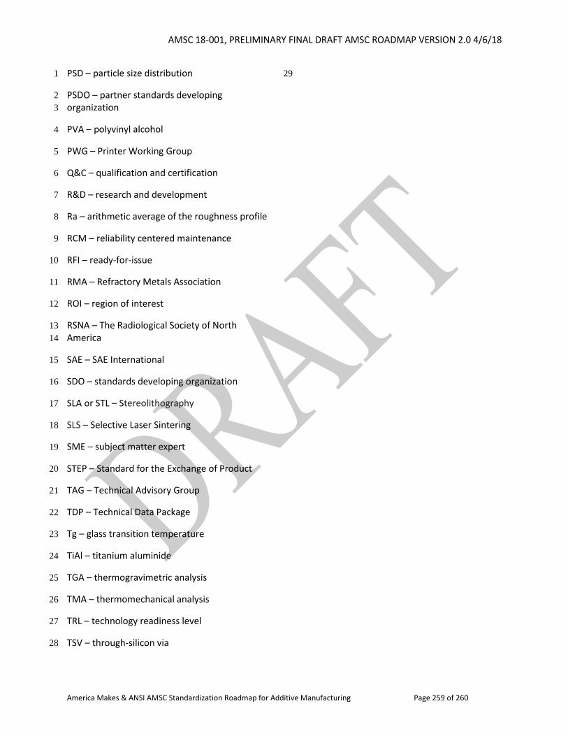
AMSC 18-001, PRELIMINARY FINAL DRAFT AMSC ROADMAP VERSION 2.0 4/6/18
America Makes & ANSI AMSC Standardization Roadmap for Additive Manufacturing Page 259 of 260
PSD – particle size distribution 1
PSDO – partner standards developing 2
organization 3
PVA – polyvinyl alcohol 4
PWG – Printer Working Group 5
Q&C – qualification and certification 6
R&D – research and development 7
Ra – arithmetic average of the roughness profile 8
RCM – reliability centered maintenance 9
RFI – ready-for-issue 10
RMA – Refractory Metals Association 11
ROI – region of interest 12
RSNA – The Radiological Society of North 13
America 14
SAE – SAE International 15
SDO – standards developing organization 16
SLA or STL – Stereolithography 17
SLS – Selective Laser Sintering 18
SME – subject matter expert 19
STEP – Standard for the Exchange of Product 20
TAG – Technical Advisory Group 21
TDP – Technical Data Package 22
Tg – glass transition temperature 23
TiAl – titanium aluminide 24
TGA – thermogravimetric analysis 25
TMA – thermomechanical analysis 26
TRL – technology readiness level 27
TSV – through-silicon via 28
29

AMSC 18-001, PRELIMINARY FINAL DRAFT AMSC ROADMAP VERSION 2.0 4/6/18
America Makes & ANSI AMSC Standardization Roadmap for Additive Manufacturing Page 260 of 260
UL – Underwriters Laboratories, Inc. 1
USAF – United States Air Force 2
UV – ultraviolet 3
V&V – verification and validation 4
VOC – volatile organic chemical 5


![byapply.combyapply.com/.../160-125-1428836998MMPDS_F240.pdf · Islami Bank Bangladesh Limited a (MMPDS) ž80 SBS-2 CIB (MMPDS) I I g 8. (fro Cl DC] ñ) C] (TIN) (21)](https://img.pdfslide.us/doc/110x75/5afe04047f8b9a994d8e608d/bank-bangladesh-limited-a-mmpds-z80-sbs-2-cib-mmpds-i-i-g-8-fro-cl-dc-.jpg)