Embed Size (px)
Citation preview

This is a new stand-alone unit. Not expansion.

KEM ONE CHEMPLAST PRIVATE LIMITED FORM-1 FOR CPVC AND ITS COMPOUNDS MANUFACTURING PLANT
AT KARAIKAL, PUDUCHERRY UT FORM I
KADAM ENVIRONMENTAL CONSULTANTS | MAY 2016 24
3 ANNEXURES
Annexure 1: Site Location Map showing Distance from Interstate Boundary

KEM ONE CHEMPLAST PRIVATE
LIMITED
FORM-1 FOR CPVC AND ITS
COMPOUNDS MANUFACTURING PLANT
AT KARAIKAL, PUDUCHERRY UT FORM I
KADAM ENVIRONMENTAL CONSULTANTS | MAY 2016 25
Annexure 2: Copy of Notification

KEM ONE CHEMPLAST PRIVATE
LIMITED
FORM-1 FOR CPVC AND ITS
COMPOUNDS MANUFACTURING PLANT
AT KARAIKAL, PUDUCHERRY UT FORM I
KADAM ENVIRONMENTAL CONSULTANTS | MAY 2016 26

KEM ONE CHEMPLAST PRIVATE
LIMITED
FORM-1 FOR CPVC AND ITS
COMPOUNDS MANUFACTURING PLANT
AT KARAIKAL, PUDUCHERRY UT FORM I
KADAM ENVIRONMENTAL CONSULTANTS | MAY 2016 27

KEM ONE CHEMPLAST PRIVATE LIMITED FORM-1 FOR CPVC AND ITS COMPOUNDS MANUFACTURING PLANT
AT KARAIKAL, PUDUCHERRY UT FORM I
KADAM ENVIRONMENTAL CONSULTANTS | MAY 2016 28
Annexure 3 : Site Location Map on Google Image

KEM ONE CHEMPLAST PRIVATE LIMITED FORM-1 FOR CPVC AND ITS COMPOUNDS MANUFACTURING PLANT
AT KARAIKAL, PUDUCHERRY UT FORM I
KADAM ENVIRONMENTAL CONSULTANTS | MAY 2016 29
Annexure 4: Site Layout Map

KEM ONE CHEMPLAST PRIVATE
LIMITED
FORM-1 FOR CPVC AND ITS
COMPOUNDS MANUFACTURING PLANT
AT KARAIKAL, PUDUCHERRY UT FORM I
KADAM ENVIRONMENTAL CONSULTANTS | MAY 2016 30
Table 1: Area Break up at Site
S. No. Item Area in m2 %
1 Processing Area 900 3.7
2 Storage Area 520 2.2
3 Effluent Treatment Plant 420 1.7
4 Cooling tower 400 1.7
5 DG Sets 510 2.1
6 Vacant Area and Roads 10037 41.5
7 Administrative Building 172 0.7
8 Greenbelt Area 7900 32.7
9 Compounding Plant 900 3.7
10 Warehouse 1500 6.2
11 Utility and Maintenance Section 600 2.5
12 11 KV Yard and Switchgear 300 1.2
Total 24159 100
KEM ONE CHEMPLAST PRIVATE
LIMITED
FORM-1 FOR CPVC AND ITS
COMPOUNDS MANUFACTURING PLANT
AT KARAIKAL, PUDUCHERRY UT FORM I
KADAM ENVIRONMENTAL CONSULTANTS | MAY 2016 31
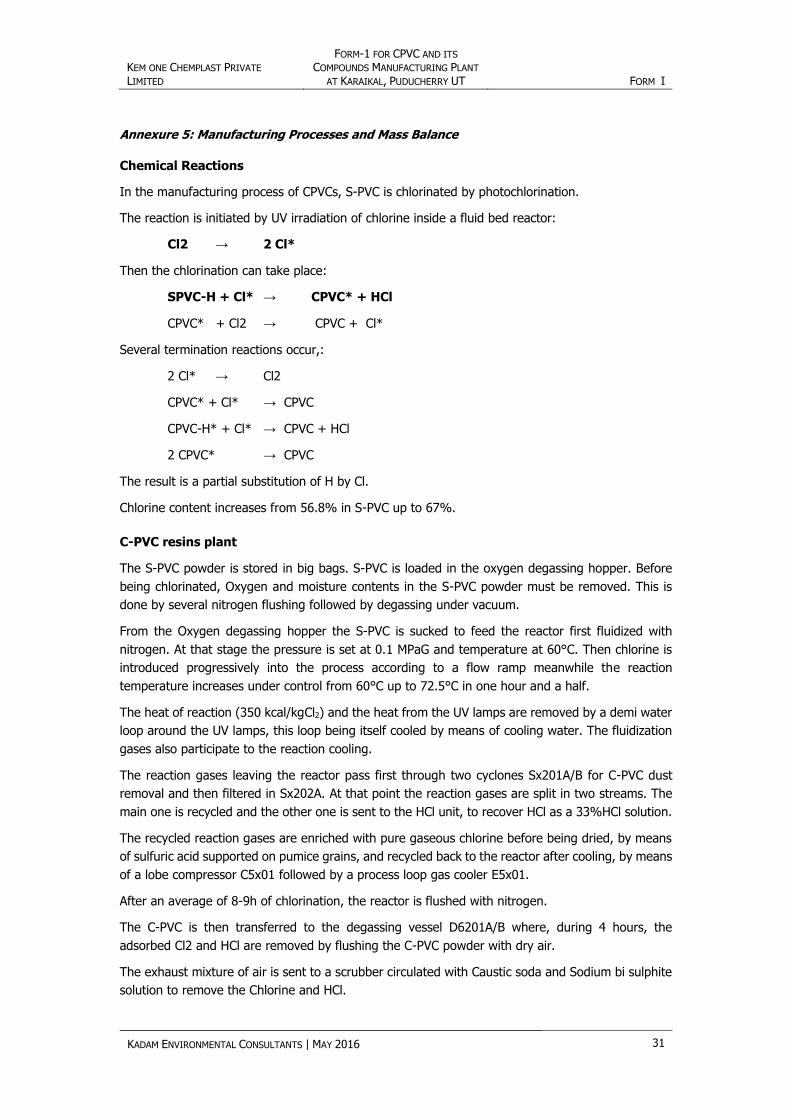
Annexure 5: Manufacturing Processes and Mass Balance
Chemical Reactions
In the manufacturing process of CPVCs, S-PVC is chlorinated by photochlorination.
The reaction is initiated by UV irradiation of chlorine inside a fluid bed reactor:
Cl2 → 2 Cl*
Then the chlorination can take place:
SPVC-H + Cl* → CPVC* + HCl
CPVC* + Cl2 → CPVC + Cl*
Several termination reactions occur,:
2 Cl* → Cl2
CPVC* + Cl* → CPVC
CPVC-H* + Cl* → CPVC + HCl
2 CPVC* → CPVC
The result is a partial substitution of H by Cl.
Chlorine content increases from 56.8% in S-PVC up to 67%.
C-PVC resins plant
The S-PVC powder is stored in big bags. S-PVC is loaded in the oxygen degassing hopper. Before
being chlorinated, Oxygen and moisture contents in the S-PVC powder must be removed. This is
done by several nitrogen flushing followed by degassing under vacuum.
From the Oxygen degassing hopper the S-PVC is sucked to feed the reactor first fluidized with
nitrogen. At that stage the pressure is set at 0.1 MPaG and temperature at 60°C. Then chlorine is
introduced progressively into the process according to a flow ramp meanwhile the reaction
temperature increases under control from 60°C up to 72.5°C in one hour and a half.
The heat of reaction (350 kcal/kgCl2) and the heat from the UV lamps are removed by a demi water
loop around the UV lamps, this loop being itself cooled by means of cooling water. The fluidization
gases also participate to the reaction cooling.
The reaction gases leaving the reactor pass first through two cyclones Sx201A/B for C-PVC dust
removal and then filtered in Sx202A. At that point the reaction gases are split in two streams. The
main one is recycled and the other one is sent to the HCl unit, to recover HCl as a 33%HCl solution.
The recycled reaction gases are enriched with pure gaseous chlorine before being dried, by means
of sulfuric acid supported on pumice grains, and recycled back to the reactor after cooling, by means
of a lobe compressor C5x01 followed by a process loop gas cooler E5x01.
After an average of 8-9h of chlorination, the reactor is flushed with nitrogen.
The C-PVC is then transferred to the degassing vessel D6201A/B where, during 4 hours, the
adsorbed Cl2 and HCl are removed by flushing the C-PVC powder with dry air.
The exhaust mixture of air is sent to a scrubber circulated with Caustic soda and Sodium bi sulphite
solution to remove the Chlorine and HCl.

KEM ONE CHEMPLAST PRIVATE
LIMITED
FORM-1 FOR CPVC AND ITS
COMPOUNDS MANUFACTURING PLANT
AT KARAIKAL, PUDUCHERRY UT FORM I
KADAM ENVIRONMENTAL CONSULTANTS | MAY 2016 32
Then the C-PVC passes through the screen S6243 and is sent to the C-PVC daily storages
R7403A/B/C.
The C-PVC resins plant has 2 reactors:
Volume 37 m3
Height 14m
12 UV stages for a total of UV Lamps-100Watts: 1532
S-PVC approximate load of 10t
C-PVC approximately produced : 12.84t
The reactor is used continuously during approximately 10 weeks before being cleaned. At that time
some UV lamps are changed if required.
Process Flow Diagram
Figure 1: Process Flow diagram of CPVC Production

KEM ONE CHEMPLAST PRIVATE
LIMITED
FORM-1 FOR CPVC AND ITS
COMPOUNDS MANUFACTURING PLANT
AT KARAIKAL, PUDUCHERRY UT FORM I
KADAM ENVIRONMENTAL CONSULTANTS | MAY 2016 33
Annexure 6: Storage Details
Table 2: Storage Details of Raw Material
S.
No. Chemical State
Consumption
(MT/Month)
Means of
Storage
Mean
Storage
Capacity, MT
No. of
Storage
Total
Storage,
MT
1 PVC Solid 1800 Bags 1 500 500
2 Sulphuric
Acid Liquid 15
Rubber Lined MS
Tanks 15 1 15
3 Additives Solid
/ Liquid
510 Bags /
Drums
Assorted bagging available
One Month Stock
500
Table 3: Storage Details of Products
S.
No. Chemical State
Production,
MTPA
Means of
Storage
Mean
Storage
Capacity, Kg
No. of
Storage
Total
Storage, MT
1 CPVC Solid 22000 Bags
25 / 500 / 675 /1000 or any
other as required by customer
15 Days 1000
2 HCl (30%) Liquid 42000 PP/FRP/ MS RL tanks
--- 15 Days 1600

KEM ONE CHEMPLAST PRIVATE
LIMITED
FORM-1 FOR CPVC AND ITS
COMPOUNDS MANUFACTURING PLANT
AT KARAIKAL, PUDUCHERRY UT FORM I
KADAM ENVIRONMENTAL CONSULTANTS | MAY 2016 34
Annexure 7: Water Consumption and Waste Water Generation Details
Table 4: Water Consumption Details
S. No. Area Water
Consumption in KLD
Effluent Generation
in KLD
Treated Effluent Disposal mode
A RO Plant 670 167 To desalination plant of
Existing Chemplast Sanmar Plant
1 Domestic 20.5 15 To be treated in STP and then treated water will be
used for Gardening
2 Cooling Tower 250 70 To desalination plant of
Existing Chemplast Sanmar Plant
3 Reactor Washing 90 90
To desalination plant of Existing Chemplast Sanmar Plant after filtration and pH
neutralization
4 Scrubber 17.5 17.5 To desalination plant of
Existing Chemplast Sanmar Plant after pH neutralization
5 HCL Synthesis 95 0 To be sold as Byproduct
6 Steam Condensate from Process 0 24 To desalination plant of
Existing Chemplast Sanmar Plant
7 Gardening 30 0
Total 503 383.5

KEM ONE CHEMPLAST PRIVATE LIMITED FORM-1 FOR CPVC AND ITS COMPOUNDS MANUFACTURING PLANT
AT KARAIKAL, PUDUCHERRY UT FORM I
KADAM ENVIRONMENTAL CONSULTANTS | MAY 2016 35
Figure 2: Water Balance
KEM ONE CHEMPLAST PRIVATE
LIMITED
FORM-1 FOR CPVC AND ITS
COMPOUNDS MANUFACTURING PLANT
AT KARAIKAL, PUDUCHERRY UT FORM I
KADAM ENVIRONMENTAL CONSULTANTS | MAY 2016 36
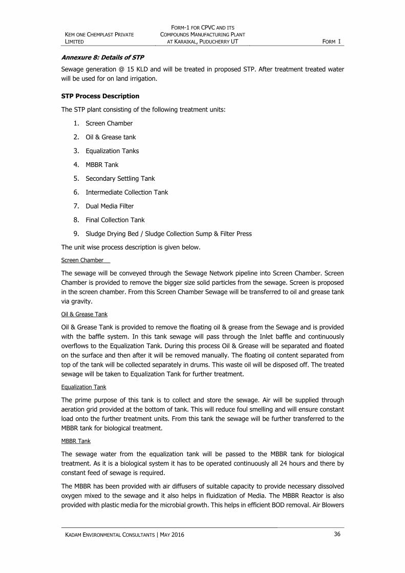
Annexure 8: Details of STP
Sewage generation @ 15 KLD and will be treated in proposed STP. After treatment treated water
will be used for on land irrigation.
STP Process Description
The STP plant consisting of the following treatment units:
1. Screen Chamber
2. Oil & Grease tank
3. Equalization Tanks
4. MBBR Tank
5. Secondary Settling Tank
6. Intermediate Collection Tank
7. Dual Media Filter
8. Final Collection Tank
9. Sludge Drying Bed / Sludge Collection Sump & Filter Press
The unit wise process description is given below.
Screen Chamber
The sewage will be conveyed through the Sewage Network pipeline into Screen Chamber. Screen
Chamber is provided to remove the bigger size solid particles from the sewage. Screen is proposed
in the screen chamber. From this Screen Chamber Sewage will be transferred to oil and grease tank
via gravity.
Oil & Grease Tank
Oil & Grease Tank is provided to remove the floating oil & grease from the Sewage and is provided
with the baffle system. In this tank sewage will pass through the Inlet baffle and continuously
overflows to the Equalization Tank. During this process Oil & Grease will be separated and floated
on the surface and then after it will be removed manually. The floating oil content separated from
top of the tank will be collected separately in drums. This waste oil will be disposed off. The treated
sewage will be taken to Equalization Tank for further treatment.
Equalization Tank
The prime purpose of this tank is to collect and store the sewage. Air will be supplied through
aeration grid provided at the bottom of tank. This will reduce foul smelling and will ensure constant
load onto the further treatment units. From this tank the sewage will be further transferred to the
MBBR tank for biological treatment.
MBBR Tank
The sewage water from the equalization tank will be passed to the MBBR tank for biological
treatment. As it is a biological system it has to be operated continuously all 24 hours and there by
constant feed of sewage is required.
The MBBR has been provided with air diffusers of suitable capacity to provide necessary dissolved
oxygen mixed to the sewage and it also helps in fluidization of Media. The MBBR Reactor is also
provided with plastic media for the microbial growth. This helps in efficient BOD removal. Air Blowers

KEM ONE CHEMPLAST PRIVATE
LIMITED
FORM-1 FOR CPVC AND ITS
COMPOUNDS MANUFACTURING PLANT
AT KARAIKAL, PUDUCHERRY UT FORM I
KADAM ENVIRONMENTAL CONSULTANTS | MAY 2016 37
for oxidation, provides the aeration. If required, Nutrients in the form of Nitrogen & Phosphate are
added for biological growth.
Secondary Settling Tank
The secondary settling tank is provided for settlement of secondary sludge solids. Biologically
treated sewage transferred to the settling tank via gravity. The sludge settled at the bottom shall
be collected in sludge drying beds or sludge collection Sump. Secondary Tube Settler is provided
with the Tube Settler Media for increasing the surface area to increasing the settling time. The clear
effluent from top of media will be transferred to intermediate collection tank.
Intermediate Collection Tank
An intermediate tank is proposed to store secondary treated sewage for tertiary disinfection
treatment. The clear sewage from the settling tank shall be collected in an intermediate collection
tank. In this tank liquid chlorine in form of Sodium Hypochlorite (NaOCl) will be mixed using aeration
grid provided at the bottom of the tank. The aeration will help to achieve effective mixing of chlorine
solution with dosage of NaOCl. The sewage is then pumped to dual media filter for tertiary
treatment.
Dual Media Filter
A Dual Media Filter will be provided for removal of residual suspended solids. Dual Media filter (DMF)
consisting of gravel, a different gradation of sand and activated carbon filter. Backwash and bypass
flow arrangements will be provided for the Dual Media Filter. The backwash water of the system
shall be taken to the Equalization Tanks.
Final Collection Tank
Outlet from Dual Media Filter will be collected in a Final Collection Tanks, where the treated sewage
will be stored. From this tank the treated sewage will be reused in flushing and gardening.
Sludge Drying Bed
The Sludge from the Secondary tube settler is pumped by sludge recirculation pump to the Sludge
Drying Beds. The Beds consist of Gravel, stones, sands to filter the water sludge. The sludge to be
dried under the sun and dried sludge will be suitably disposed & the filtrate will be taken to the
equalization tank.
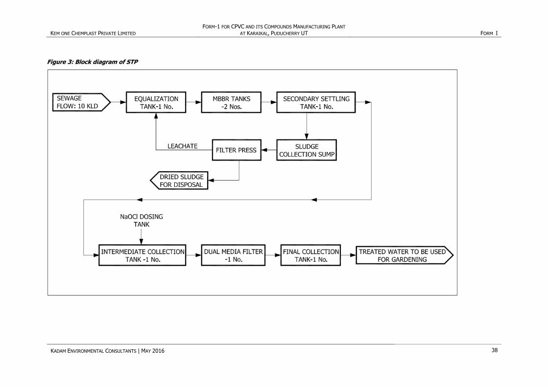
Flow diagram for proposed sewage treatment plants is given in Figure 3.
KEM ONE CHEMPLAST PRIVATE LIMITED FORM-1 FOR CPVC AND ITS COMPOUNDS MANUFACTURING PLANT
AT KARAIKAL, PUDUCHERRY UT FORM I
KADAM ENVIRONMENTAL CONSULTANTS | MAY 2016 38
Figure 3: Block diagram of STP

KEM ONE CHEMPLAST PRIVATE
LIMITED
FORM-1 FOR CPVC AND ITS
COMPOUNDS MANUFACTURING PLANT
AT KARAIKAL, PUDUCHERRY UT FORM I
KADAM ENVIRONMENTAL CONSULTANTS | MAY 2016 39
Annexure 9: Fuel Consumption
Table 5: Fuel Consumption Details
S.
No.
Stack
Attached to Capacity
Stack
Nos.
Stack
Height
Type of Fuel
used
Fuel
consumption
1 DG Set 500 kVA 1 11 HSD 125 L/hr
Note: DG Set will be used for emergency purpose.
KEM ONE CHEMPLAST PRIVATE
LIMITED
FORM-1 FOR CPVC AND ITS
COMPOUNDS MANUFACTURING PLANT
AT KARAIKAL, PUDUCHERRY UT FORM I
KADAM ENVIRONMENTAL CONSULTANTS | MAY 2016 40
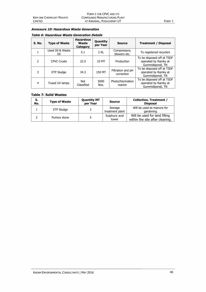
Annexure 10: Hazardous Waste Generation
Table 6: Hazardous Waste Generation Details
S. No. Type of Waste Hazardous
Waste Category
Quantity per Year
Source Treatment / Disposal
1 Used Oil & Waste
Oil 5.1 2 KL
Compressors, blowers etc.
To registered recyclers
2 CPVC Crusts 22.5 10 MT Production To be disposed off at TSDF
operated by Ramky at Gummidipondi, TN
3 ETP Sludge 34.3 150 MT Filtration and pH
correction
To be disposed off at TSDF operated by Ramky at
Gummidipondi, TN
4 Fused UV lamps Not
Classified 5000 Nos.
Photochlorination reactor
To be disposed off at TSDF operated by Ramky at
Gummidipondi, TN
Table 7: Solid Wastes
S. No.
Type of Waste Quantity MT
per Year Source
Collection, Treatment / Disposal
1 STP Sludge 2 Sewage
treatment plant Will be used as manure for
gardening
2 Pumice stone 5 Sulphuric acid
tower
Will be used for land filling
within the site after cleaning.

KEM ONE CHEMPLAST PRIVATE
LIMITED
FORM-1 FOR CPVC AND ITS
COMPOUNDS MANUFACTURING PLANT
AT KARAIKAL, PUDUCHERRY UT FORM I
KADAM ENVIRONMENTAL CONSULTANTS | MAY 2016 41
Annexure 11: Stack Details
Table 8: Stacks Details
Stack Attached to Sources Capacity Nos. of Stacks Stack Height, m
DG Set 500 kVA 1 11
Table 9: Details of Process Vents
Stack Attached to Nos. of Stacks
Stack Height in m
Pollutants Emitted
Air Pollution Control Measures Attached
HCl synthesis 1 30 HCl & Chlorine Absorption tower using water as an absorption
media
CPVC Reactor and De-gassing vessel
1 12 Chlorine Alkaline scrubber
PVC Conveying to Silo 1 25 PM Bag Filter
PVC Conveying to Oxygen Degassing
1 10 PM Bag Filter
Conveying - Degassing Vessel to Hopper
1 25 PM Bag Filter
Evacuation of air 1 10 PM Bag Filter
Conveying CPVC from Reactor
1 25 PM Bag Filter
Conveying CPVC to Compounds
1 25 PM Bag filter
CONTACT DETAILS
Vadodara (Head Office)
871/B/3, GIDC Makarpura, Vadodara, India – 390 010.
E: [email protected]; T:+91-265-3001000; F: +91-265-3001069
Delhi / NCR
Spaze IT Park, Unit No. 1124, 11th Floor, Tower B-3, Sector 49, Sohna Road, Gurgaon, India – 122 002
E: [email protected]; T/F : 0124-424 2430-436
Kadam Environmental Consultants w w w . ka d a m en v i r o . c o m
Envi ronment for Deve lopment