Embed Size (px)
Citation preview
7/29/2019 Stand Alone Power
http://slidepdf.com/reader/full/stand-alone-power 1/28
Stand Alone Power
© The State of Queensland (TAFE Queensland) 2008
16, January 2009
Version 01 Revision 01
flexiblelearning.net.au
7/29/2019 Stand Alone Power
http://slidepdf.com/reader/full/stand-alone-power 2/28
Stand Alone Power
Australian Flexible Learning Framework i
The views expressed herein do not necessarily represent the views of the Commonwealth of Australia.
©Commonwealth of Australia 2008
This work is copyright. Apart from any use as permitted under the Copyright Act 1968, no part may be reproducedwithout prior written permission. However, permission is given to trainers and teachers to make copies byphotocopying or other duplicating processes for use within their own training organisation or in a workplace where thetraining is being conducted. This permission does not extend to the making of copies for use outside the immediatetraining environment for which they are made, nor the making of copies for hire or resale to third parties. Requestsand inquiries concerning other reproduction and rights should be directed in the first instance to the Director, ICTPolicy Section, Department of Education, Employment and Workplace Relations, GPO Box 9880, Canberra, ACT,2601.
7/29/2019 Stand Alone Power
http://slidepdf.com/reader/full/stand-alone-power 3/28
Stand Alone Power
Australian Flexible Learning Framework i
Table of contents
Introduction.............................................................................................................................. 1
The major components of a Stand-alone Power system..................................................... 1
Voltage regulation ................................................................................................................... 3
Types of Regulators.......................................................................................................... 3
Connection of Regulators ................................................................................................. 7
Selection and Sizing of Regulators................................................................................... 9
Self Regulating PV Modules............................................................................................. 9
Inverters.................................................................................................................................. 10 Principle of Operation..................................................................................................... 10
Other inverter types and system configurations ............................................................. 13
Selection & Sizing of Inverters........................................................................................ 13
Battery chargers.................................................................................................................... 14
Selection and Sizing of Battery Charger......................................................................... 15
Back-up generators............................................................................................................... 16
Sizing of Generator......................................................................................................... 17
Circuit protection................................................................................................................... 18
Battery cable protection.................................................................................................. 19
Renewable input protection............................................................................................19
Battery charger protection............................................................................................... 19
DC load Protection.......................................................................................................... 19
AC circuit protection........................................................................................................ 19
DC control board ................................................................................................................... 19
System efficiency .................................................................................................................. 20
Glossary ................................................................................................................................. 22
Bibliography........................................................................................................................... 24
7/29/2019 Stand Alone Power
http://slidepdf.com/reader/full/stand-alone-power 4/28
Stand Alone Power
Australian Flexible Learning Framework 1
Introduction
This Unit describes the components of a Stand-alone Power System (SPS). An
SPS is a system which supplies electric power to a user, and is not connected to thepower distribution systems of an electricity supply authority. Stand-alone powersystems are supplied with power from one or more of a number of sources includingbut not limited to: a photovoltaic array, a wind turbine generator, a micro-hydrogenerator or a engine generator set.
This unit covers the function, operation and efficiency, selection and configuration of components in a typical system. Stand-alone Power Systems are also known asRemote Area Power Systems (RAPS), but since they are used in places which arenot necessarily remote, the term SPS is preferred. Renewable energy basedgenerators and batteries are covered in detail in other units.
Regulators, inverters, battery chargers and generating sets are dealt with here indetail, along with connection of equipment, circuit protection and system efficiency.
The major components of a Stand-alone Power system
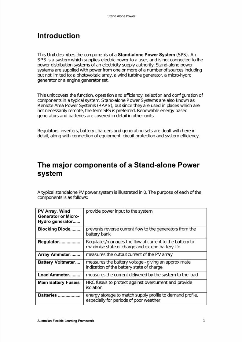
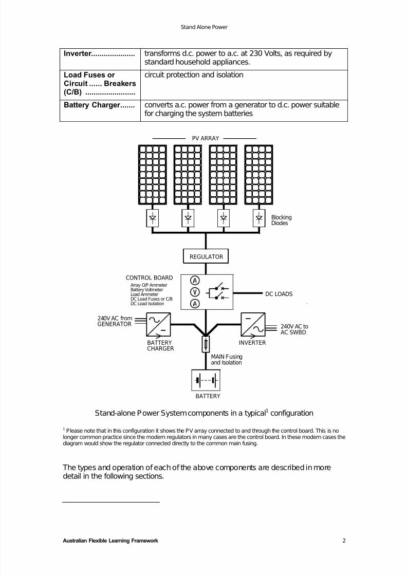
A typical standalone PV power system is illustrated in 0. The purpose of each of thecomponents is as follows:
PV Array, WindGenerator or Micro-Hydro generator......
provide power input to the system
Blocking Diode........ prevents reverse current flow to the generators from thebattery bank.
Regulator ................. Regulates/manages the flow of current to the battery tomaximise state of charge and extend battery life.
Array Ammeter ........ measures the output current of the PV array
Battery Voltmeter .... measures the battery voltage - giving an approximateindication of the battery state of charge
Load Ammeter......... measures the current delivered by the system to the load
Main Battery Fuse/s HRC fuse/s to protect against overcurrent and provideisolation
Batteries .................. energy storage to match supply profile to demand profile,
especially for periods of poor weather
7/29/2019 Stand Alone Power
http://slidepdf.com/reader/full/stand-alone-power 5/28
Stand Alone Power
Australian Flexible Learning Framework 2
Inverter ..................... transforms d.c. power to a.c. at 230 Volts, as required bystandard household appliances.
Load Fuses or Circuit ...... Breakers(C/B) ........................
circuit protection and isolation
Battery Charger ....... converts a.c. power from a generator to d.c. power suitablefor charging the system batteries
240V AC to
REGULATOR
Array O/P AmmeterBattery VoltmeterLoad AmmeterDC Load Fuses or C/B
DC Load Isolation
240V AC fromGENERATOR
BATTERYCHARGER
CONTROL BOARD
INVERTER
MAIN Fusingand Isolation
BATTERY
DC LOADS
AC SWBD
PV ARRAY
BlockingDiodes
Stand-alone Power System components in a typical1 configuration
1Please note that in this configuration it shows the PV array connected to and through the control board. This is no
longer common practice since the modern regulators in many cases are the control board. In these modern cases thediagram would show the regulator connected directly to the common main fusing.
The types and operation of each of the above components are described in moredetail in the following sections.
7/29/2019 Stand Alone Power
http://slidepdf.com/reader/full/stand-alone-power 6/28
Stand Alone Power
Australian Flexible Learning Framework 3
The operation of the system is as follows:
• Power is supplied from the renewable energy source, through the regulator, to thed.c. control board (e.g. 1000 W).
• Some power is used by the d.c. loads (e.g. 100 W) and the inverter (e.g. 500 W)and the remainder then flows to the battery (e.g. 400 W).
• When there is insufficient power from the renewable energy source to meet theloads (e.g. a photovoltaic system at night), the battery supplies power to make upthe difference.
• When the backup generator is operating, power flows through the battery chargerto the d.c. bus, in effect adding to the power from the renewable energy source.Note that power flow between the battery and the d.c. control board can be ineither direction, depending on the balance between supply and demand for power.
Voltage regulation
The basic role of the regulator is to provide battery charge management with a viewto maximising battery life. It must:
• supply maximum current when the battery state of charge is low and• reduce the battery charge current as state of charge approaches 100%
• provide temperature compensated battery charging (only in modern units)• provide a low battery voltage warning or load disconnection
• reduce electrolyte stratification in flooded lead acid cells
Most modern regulators have an operating efficiency of at least 0.95 at their ratedoutput.
Types of Regulators
Most regulators use a simple Boost/Float charge regime. The regulator will providecurrent to a battery until the battery reaches full charge (Boost mode) and then willallow the battery voltage to drop back to a float voltage (Float mode). This boost
voltage is always above the gassing voltage of the battery (the process of gassing isexplained in Unit 9).
The regulator will then remain in Float mode, maintaining the battery voltage at thefloat level, until the battery voltage drops lower due to the provision of power to aload. The regulator then returns to Boost mode.
Some more complex regulator-controllers will enhance this scheme by makingprovision for periodic equalise charge at a higher voltage (an equalise chargeattempts to ensure that all cells of a battery are fully and evenly charged - refer Unit
9 Energy Storage).
7/29/2019 Stand Alone Power
http://slidepdf.com/reader/full/stand-alone-power 7/28
Stand Alone Power
Australian Flexible Learning Framework 4
For flooded cell lead-acid batteries,
− the Boost voltage is 2.45 to 2.5 volts per cell and
− the Float voltage is 2.3 to 2.4 volts per cell.
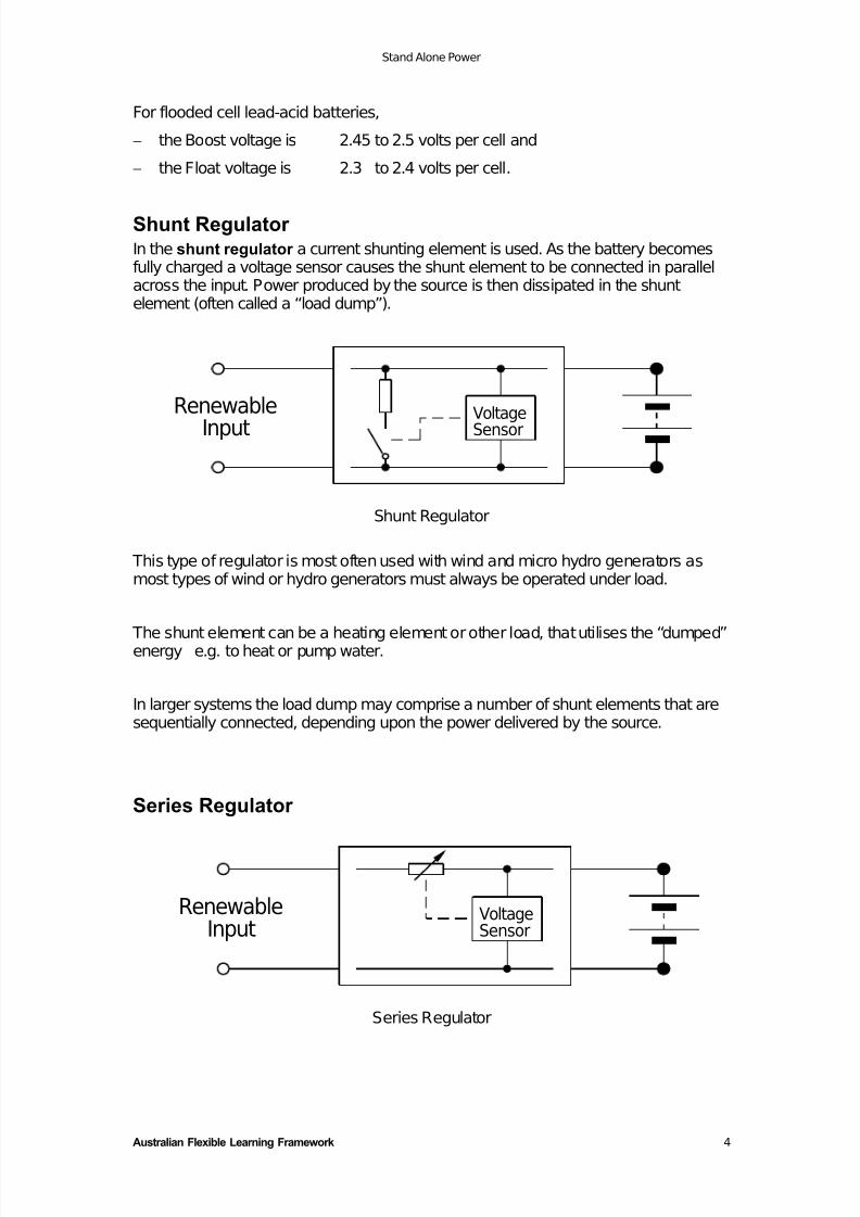
Shunt Regulator In the shunt regulator a current shunting element is used. As the battery becomesfully charged a voltage sensor causes the shunt element to be connected in parallelacross the input. Power produced by the source is then dissipated in the shuntelement (often called a “load dump”).
Renewable
InputVoltageSensor
Shunt Regulator
This type of regulator is most often used with wind and micro hydro generators asmost types of wind or hydro generators must always be operated under load.
The shunt element can be a heating element or other load, that utilises the “dumped”energy e.g. to heat or pump water.
In larger systems the load dump may comprise a number of shunt elements that aresequentially connected, depending upon the power delivered by the source.
Series Regulator
RenewableInput
VoltageSensor
Series Regulator
7/29/2019 Stand Alone Power
http://slidepdf.com/reader/full/stand-alone-power 8/28
Stand Alone Power
Australian Flexible Learning Framework 5
In a series regulator a variable resistance element in series with the battery limitsthe current flow. Here a voltage sensor controls the resistance to reduce the currentas the battery voltage rises.
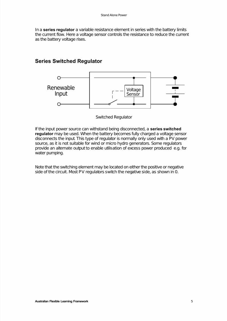
Series Switched Regulator
VoltageSensor
RenewableInput
Switched Regulator
If the input power source can withstand being disconnected, a series switchedregulator may be used. When the battery becomes fully charged a voltage sensordisconnects the input. This type of regulator is normally only used with a PV powersource, as it is not suitable for wind or micro hydro generators. Some regulatorsprovide an alternate output to enable utilisation of excess power produced e.g. forwater pumping.
Note that the switching element may be located on either the positive or negativeside of the circuit. Most PV regulators switch the negative side, as shown in 0.
7/29/2019 Stand Alone Power
http://slidepdf.com/reader/full/stand-alone-power 9/28
Stand Alone Power
Australian Flexible Learning Framework 6
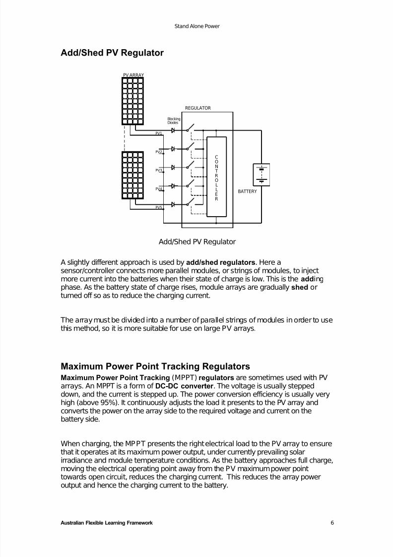
Add/Shed PV Regulator
REGULATOR
PV5
PV ARRAY
PV4
PV3
PV2
PV1
BlockingDiodes
CON TROLL
ER
BATTERY
Add/Shed PV Regulator
A slightly different approach is used by add/shed regulators. Here asensor/controller connects more parallel modules, or strings of modules, to injectmore current into the batteries when their state of charge is low. This is the addingphase. As the battery state of charge rises, module arrays are gradually shed orturned off so as to reduce the charging current.
The array must be divided into a number of parallel strings of modules in order to usethis method, so it is more suitable for use on large PV arrays.
Maximum Power Point Tracking RegulatorsMaximum Power Point Tracking (MPPT) regulators are sometimes used with PVarrays. An MPPT is a form of DC-DC converter . The voltage is usually steppeddown, and the current is stepped up. The power conversion efficiency is usually veryhigh (above 95%). It continuously adjusts the load it presents to the PV array andconverts the power on the array side to the required voltage and current on thebattery side.
When charging, the MPPT presents the right electrical load to the PV array to ensurethat it operates at its maximum power output, under currently prevailing solarirradiance and module temperature conditions. As the battery approaches full charge,moving the electrical operating point away from the PV maximum power pointtowards open circuit, reduces the charging current. This reduces the array power
output and hence the charging current to the battery.
7/29/2019 Stand Alone Power
http://slidepdf.com/reader/full/stand-alone-power 10/28
Stand Alone Power
Australian Flexible Learning Framework 7
Generator Field ControlVoltage and current regulation in rotating machines (alternators and dc generators)can be achieved by controlling the magnetic field of the generator. In theseregulators, changing the field current varies the strength of the magnetic field.
Field control regulators are sometimes used with WECS.
For MHS supplying instantaneous a.c. power demand, field control can be used if coupled with a spear valve (to control the volume of water) to maintain the turbinespeed and alternator voltage steady despite load changes.
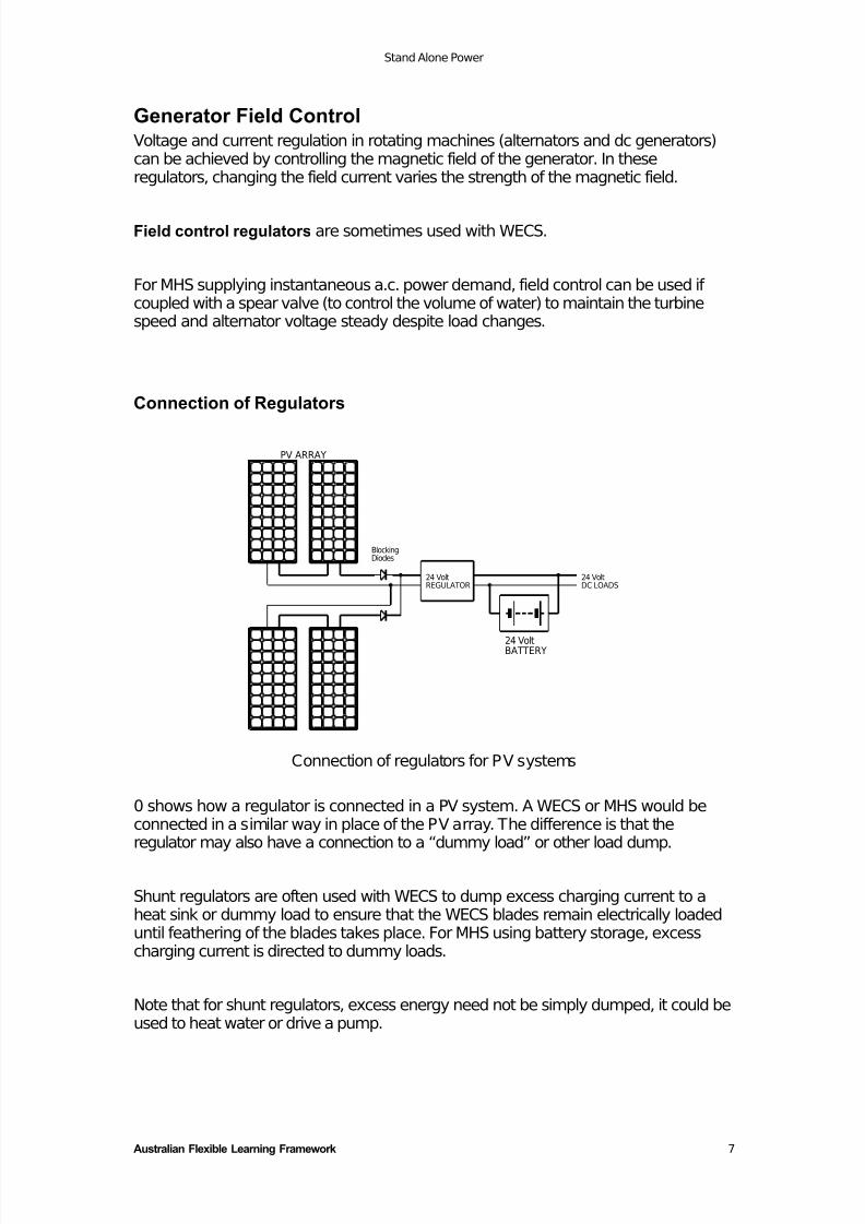
Connection of Regulators
PV ARRAY
BlockingDiodes
24 VoltBATTERY
24 VoltREGULATOR
24 VoltDC LOADS
Connection of regulators for PV systems
0 shows how a regulator is connected in a PV system. A WECS or MHS would beconnected in a similar way in place of the PV array. The difference is that theregulator may also have a connection to a “dummy load” or other load dump.
Shunt regulators are often used with WECS to dump excess charging current to aheat sink or dummy load to ensure that the WECS blades remain electrically loadeduntil feathering of the blades takes place. For MHS using battery storage, excesscharging current is directed to dummy loads.
Note that for shunt regulators, excess energy need not be simply dumped, it could beused to heat water or drive a pump.
7/29/2019 Stand Alone Power
http://slidepdf.com/reader/full/stand-alone-power 11/28
Stand Alone Power
Australian Flexible Learning Framework 8
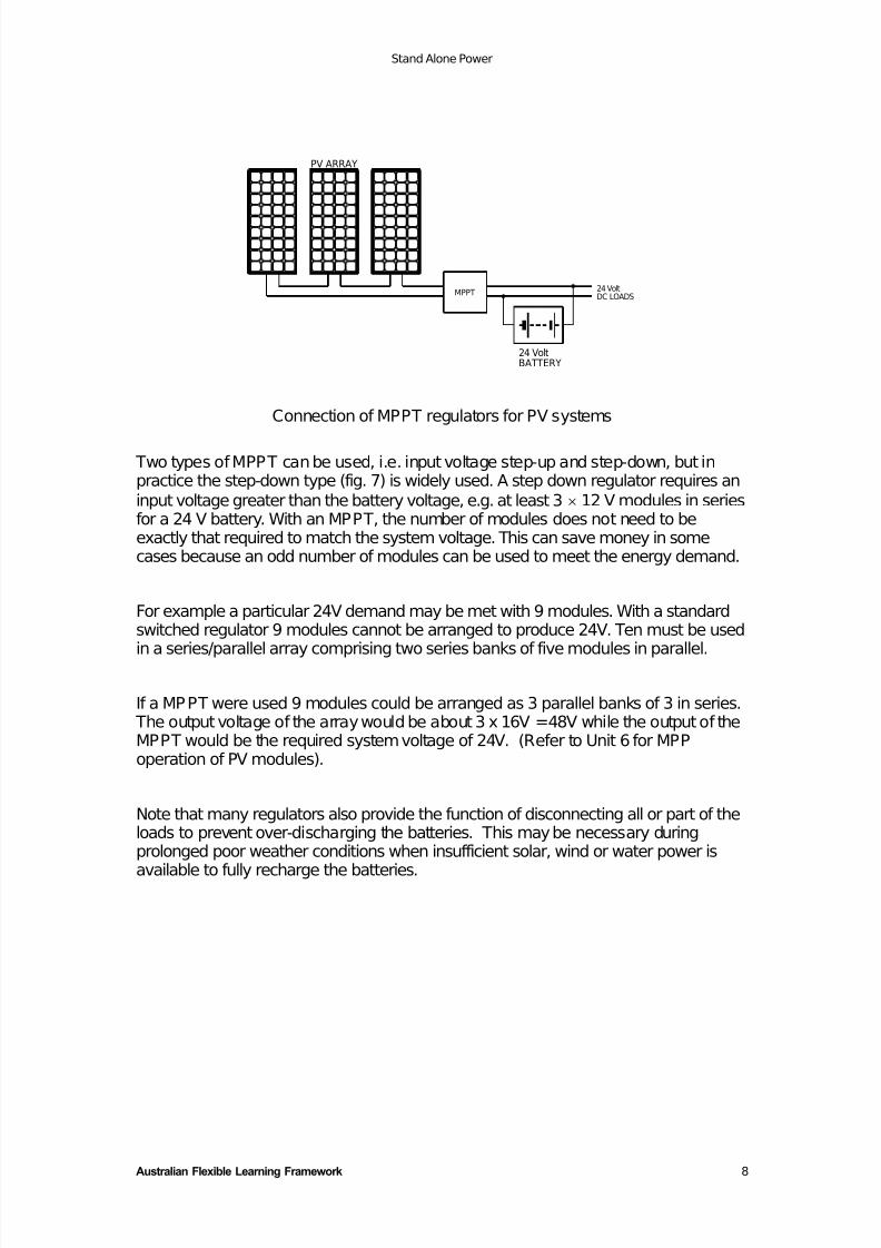
PV ARRAY
24 VoltBATTERY
MPPT24 VoltDC LOADS
Connection of MPPT regulators for PV systems
Two types of MPPT can be used, i.e. input voltage step-up and step-down, but inpractice the step-down type (fig. 7) is widely used. A step down regulator requires an
input voltage greater than the battery voltage, e.g. at least 3 × 12 V modules in seriesfor a 24 V battery. With an MPPT, the number of modules does not need to beexactly that required to match the system voltage. This can save money in somecases because an odd number of modules can be used to meet the energy demand.
For example a particular 24V demand may be met with 9 modules. With a standardswitched regulator 9 modules cannot be arranged to produce 24V. Ten must be used
in a series/parallel array comprising two series banks of five modules in parallel.
If a MPPT were used 9 modules could be arranged as 3 parallel banks of 3 in series. The output voltage of the array would be about 3 x 16V = 48V while the output of theMPPT would be the required system voltage of 24V. (Refer to Unit 6 for MPPoperation of PV modules).
Note that many regulators also provide the function of disconnecting all or part of theloads to prevent over-discharging the batteries. This may be necessary duringprolonged poor weather conditions when insufficient solar, wind or water power is
available to fully recharge the batteries.
7/29/2019 Stand Alone Power
http://slidepdf.com/reader/full/stand-alone-power 12/28
Stand Alone Power
Australian Flexible Learning Framework 9
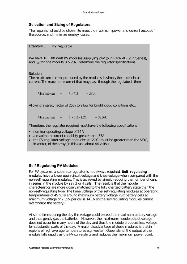
Selection and Sizing of Regulators
The regulator should be chosen to meet the maximum power and current output of the source, and minimize energy losses.
Example 1 PV regulator
We have 10 × 80 Watt PV modules supplying 24V (5 in Parallel × 2 in Series),and ISC for one module is 5.2 A. Determine the regulator specifications.
Solution: The maximum current produced by the modules is simply the short circuitcurrent. The maximum current that may pass through the regulator is then
Max current = 5 × 5.2 = 26 A
Allowing a safety factor of 25% to allow for bright cloud conditions etc.,
Max current = 5 × 5.2× 1.25 = 32.5A.
Therefore, the regulator required must have the following specifications:
• nominal operating voltage of 24 V
• a maximum current capability greater than 33A• the PV regulator voltage open circuit (VOC) must be greater than the VOC,
in winter, of the array (in this case about 44 volts.)
Self Regulating PV Modules
For PV systems, a separate regulator is not always required. Self- regulating modules have a lower open circuit voltage and knee voltage when compared with thenon-self regulating modules. This is achieved by simply reducing the number of cells
in series in the module by say 3 or 4 cells. The result is that the modulecharacteristics are more closely matched to the fully charged battery state than thenon-self-regulating type. The knee voltage of the self-regulating modules at operatingtemperatures of 45 °C is around maximum battery voltage. (Six battery cells atmaximum voltage of 2.35V per cell is 14.1V so the self-regulating modules cannotovercharge the battery).
At some times during the day the voltage could exceed the maximum battery voltageand thus gently gas the batteries. However, the maximum module output voltagedoes not occur for many hours of the day and thus the module produces less voltagefor substantial parts of the day. A major disadvantage of these modules is that in
regions of high average temperatures e.g. western Queensland, the output of themodule falls rapidly as the I-V curve shifts and reduces the maximum power point.
7/29/2019 Stand Alone Power
http://slidepdf.com/reader/full/stand-alone-power 13/28
Stand Alone Power
Australian Flexible Learning Framework 10
This type of module is not recommended since it is difficult to ensure that thebatteries will be neither over- or under-charged for prolonged periods. They may findsome application in low cost systems, or applications where the PV modules usuallysupply a small proportion of the total energy required. Where energy is drawn on adaily basis the re-charging rate is usually not high enough and it is better to usestandard modules together with a regulator.
This will allow greater charging currents and hence faster, fuller charging.
Inverters
An inverter is a device that transforms d.c. battery voltage and current to a.c. power,
similar to that provided from the a.c. mains. This is necessary so that standard 230V(in Australia) a.c. appliances can be powered from a Stand-alone Power System. ACappliances are generally more readily available than their d.c. equivalents.
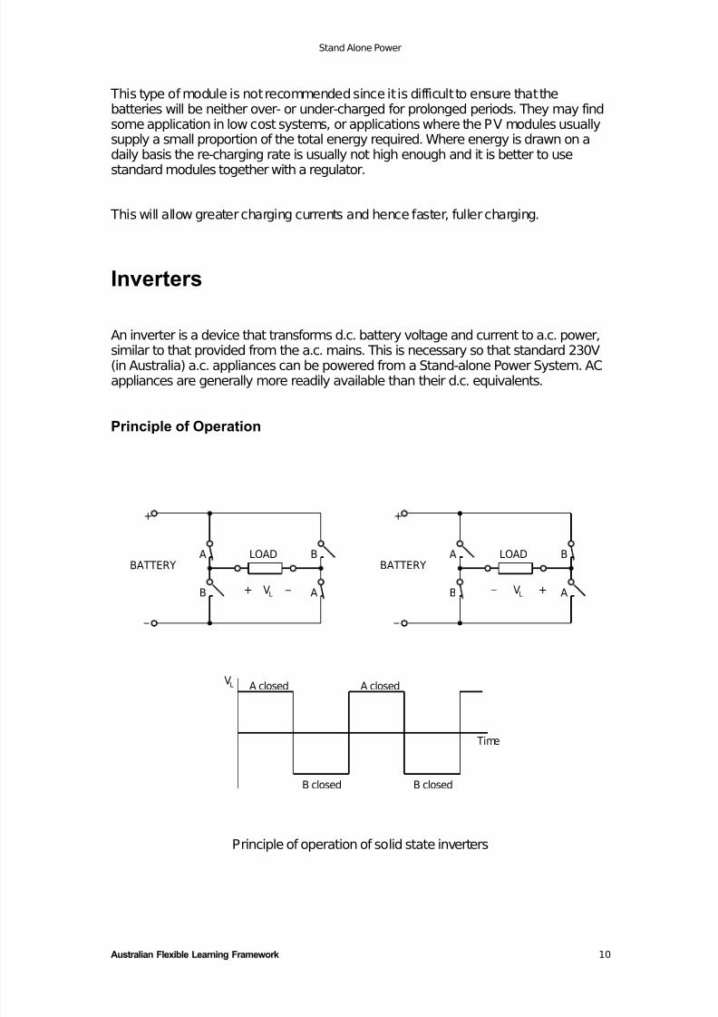
Principle of Operation
A closedV
_
BATTERY
+
A
B
B closed
A closedL
LOAD
+ _ VL A
B LOAD
L
_
B closed
Time
+
BATTERYA
B V _
A
B
+
Principle of operation of solid state inverters
7/29/2019 Stand Alone Power
http://slidepdf.com/reader/full/stand-alone-power 14/28
Stand Alone Power
Australian Flexible Learning Framework 11
0 illustrates the basic principle of operation of the inverter. A set of semiconductorswitches first connects voltage to the load in one direction then the other. Switches Aand B can never be operated at the same time, i.e. when A switches are closed, Bswitches are open and visa versa.
When the A switches are closed the voltage is connected to the load, giving a loadvoltage , VL, of the polarity shown in the left hand diagram above. When B switchesare closed the voltage is connected to the load in the opposite sense, and the polarityof VL is reversed.
This switching procedure is repeated at a regular rate (50 cycles per second, or 50Hertz) and produces the basic alternating voltage & current. This is then fed througha transformer to step up the voltage to the required 230 V (230V is the new standardac voltage for Australia).
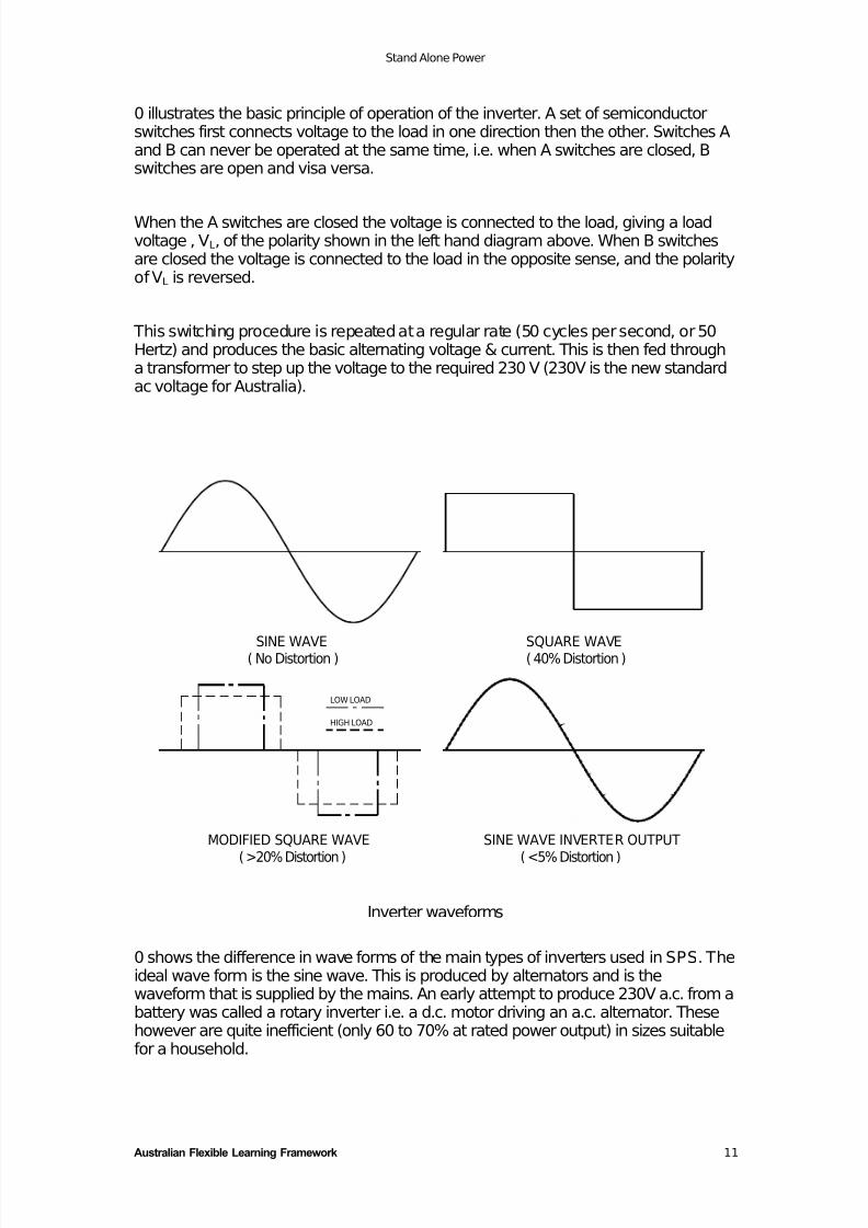
Inverter waveforms
0 shows the difference in wave forms of the main types of inverters used in SPS. Theideal wave form is the sine wave. This is produced by alternators and is thewaveform that is supplied by the mains. An early attempt to produce 230V a.c. from abattery was called a rotary inverter i.e. a d.c. motor driving an a.c. alternator. Thesehowever are quite inefficient (only 60 to 70% at rated power output) in sizes suitablefor a household.
MODIFIED SQUARE WAVE
( >20% Distortion )
( No Distortion )SINE WAVE
HIGH LOAD
LOW LOAD
SINE WAVE INVERTER OUTPUT
( <5% Distortion )
SQUARE WAVE( 40% Distortion )
7/29/2019 Stand Alone Power
http://slidepdf.com/reader/full/stand-alone-power 15/28
Stand Alone Power
Australian Flexible Learning Framework 12
Early solid state (i.e. electronic) inverters produced a square wave output. Thesquare wave inverter always outputs the same wave shape irrespective of thepower demand of the load. This results in very poor efficiency at low load. In addition,there is no way of adjusting the voltage to keep it constant when the battery voltageor load changes. A high frequency type of square wave inverter is still in wide use -d.c. lighting inverters. These can operate at high efficiency because they arespecially designed to power a fixed load i.e. a single fluorescent tube.
A performance improvement is realised with modified square wave inverters. In themodified square wave inverter, the width of the pulse can be adjusted to compensatefor changes in battery voltage or losses. This maintains the same rms (route of themeans squared or effective) voltage even though the peak voltage of the pulse maychange. It also draws less power from the battery when the load has low powerdemands. As a result the modified square wave inverter provides excellent voltageregulation for the ac power, and is more efficient than the square wave inverter at lowloads. They also have excellent surge power capacity which is useful for starting
motors in particular. Modified square wave inverters are also sometimes called“modified sine wave inverters”, however this is really misleading terminology.
The rectangular wave shapes produced by the square wave and modified squarewave inverters contain many high frequency harmonics, i.e. the basic frequency of the wave shape is 50 Hz but there is also a lot of energy at 150 Hz, 250 Hz, 350 Hz,450 Hz etc. (square waves contain all the odd harmonics).
When motors are driven by these inverters they respond to the 50 Hz component butthe motor is unable to respond to the high frequency harmonics. As a result these
harmonics produce heat in the motor. This is not usually a problem unless the motoris in a very warm or unventilated place or the motor is of very cheap construction,e.g. common air circulation fan motors. The high frequency harmonics can alsocause noise problems with radio, TV and communications equipment. Someappliances have trouble running off modified square wave inverters. This particularlyapplies to products with timers or variable speed control.
The latest development of inverter technology is microprocessor basedsine waveinverters. These inverters generally use high frequency switching to produce manysmall pieces of a sine wave, which are then smoothed out by a filter. This techniqueproduces a waveform almost identical to the ideal “sine wave” over a wide range of
loads. This avoids the problems with pulse-width modulated (PWM) square waveinverters and provides a ‘higher quality’ waveform, which can run any type of appliance.
Because of their microprocessor control, many sine wave inverters can also providea large range of additional functions, such as:
• Battery voltage monitoring
• Inverter d.c. current monitoring• Energy monitoring
• Grid or generator synchronisation
• Generator start / stop signals
7/29/2019 Stand Alone Power
http://slidepdf.com/reader/full/stand-alone-power 16/28
Stand Alone Power
Australian Flexible Learning Framework 13
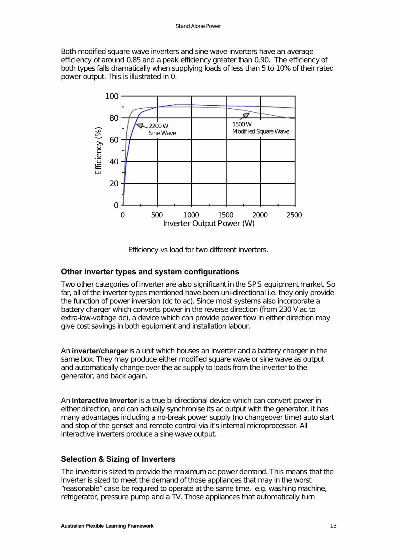
Both modified square wave inverters and sine wave inverters have an averageefficiency of around 0.85 and a peak efficiency greater than 0.90. The efficiency of both types falls dramatically when supplying loads of less than 5 to 10% of their ratedpower output. This is illustrated in 0.
Efficiency vs load for two different inverters.
Other inverter types and system configurations
Two other categories of inverter are also significant in the SPS equipment market. So
far, all of the inverter types mentioned have been uni-directional i.e. they only providethe function of power inversion (dc to ac). Since most systems also incorporate abattery charger which converts power in the reverse direction (from 230 V ac toextra-low-voltage dc), a device which can provide power flow in either direction maygive cost savings in both equipment and installation labour.
An inverter/charger is a unit which houses an inverter and a battery charger in thesame box. They may produce either modified square wave or sine wave as output,and automatically change over the ac supply to loads from the inverter to thegenerator, and back again.
An interactive inverter is a true bi-directional device which can convert power ineither direction, and can actually synchronise its ac output with the generator. It hasmany advantages including a no-break power supply (no changeover time) auto startand stop of the genset and remote control via it’s internal microprocessor. Allinteractive inverters produce a sine wave output.
Selection & Sizing of Inverters
The inverter is sized to provide the maximum ac power demand. This means that theinverter is sized to meet the demand of those appliances that may in the worst
“reasonable” case be required to operate at the same time, e.g. washing machine,refrigerator, pressure pump and a TV. Those appliances that automatically turn
0
20
40
60
80
100
E f f i c i e n c y ( % )
0 500 1000 1500 2000 2500
Inverter Output Power (W)
1500 WModified Square Wave
2200 WSine Wave
7/29/2019 Stand Alone Power
http://slidepdf.com/reader/full/stand-alone-power 17/28
Stand Alone Power
Australian Flexible Learning Framework 14
themselves on and off, such as refrigerators and water pressure pumps, must beincluded.
Example 2
A household’s appliances may include a washing machine (400VA) plus fridge(160VA) plus pump (260VA) plus TV (80VA): a total of 900VA.
A 900VA inverter would be sufficient to power these appliances while running.
It is important to also cater for current surges (on startup) of loads such as motors.In the above example the induction motor of the washing machine could surge to 7times the normal operating current at start up. The inverter must therefore be ableto surge to 7 times the power, i.e. 7 x 400VA = 2800VA.
The other loads will be on at the same time, so the total surge load is2800+160+260+80 = 3300 VA. The inverter must be capable of meeting both themaximum and surge demands. In practice it is found that most inverters can surgeto about 2 to 3 times their rated power, which means that a 900 VA inverterprobably would handle no more than a 2700 VA surge. Hence the inverter requiredto meet a 3.3 kVA surge will probably turn out to be one rated at about 1.1 - 1.6kVA.
It is best to estimate or measure the apparent power consumption (VA) of eachappliance rather than the true power (Watts) since the inverter must be able to supply
the total current × volts at any instance. Note that for any inductive or capacitive loadthe apparent power is greater than the true power and can be estimated astrue power (Watts)
power factor . A typical value for power factor is 0.8. Neglecting to consider this
important point can result in an undersized inverter.
Battery chargers
The function of the battery charger is to use electrical energy from a diesel or petrolgenerator to recharge the battery bank. In other words, it converts ac power at mainsvoltage (230 V), to dc power at the battery voltage (e.g. 24V).
There are two major types of battery chargers for lead acid batteries -
• unregulated, and
• electronically regulated types
7/29/2019 Stand Alone Power
http://slidepdf.com/reader/full/stand-alone-power 18/28
Stand Alone Power
Australian Flexible Learning Framework 15
The first is a standard transformer type charger. The charger will initially supply itsrated current output to a battery with a low state of charge. As the battery voltagerises the charging current will fall, eventually stabilising at a final voltage with a tricklecharge. Some chargers have provision to adjust the charge rate and final voltage e.g.by selecting different tappings on the transformer secondary winding.
The electronically regulated charger provides a current limited maximum output anda regulated maximum voltage on the output. A constant current (the current limit) issupplied to the battery until it approaches full charge, at around the voltage regulationpoint. The current is then tapered off until a ‘float’ level is reached, which maintainsthe battery at full charge. Some chargers of this type use high frequency switchmodetechniques which remove the need for a large heavy transformer. This results in asmaller, lightweight charger. Chargers using microprocessor control may use morecomplex charging procedures.
The major differences between these two chargers is that electronic regulation allowsfaster charging, giving maximum charge rate right up to the final voltage - and the
final voltage can be accurately regulated. Accurate voltage regulation can prolong thelife of any battery, but is especially important for “sealed” i.e. valve regulated,batteries.
Battery charger efficiency would typically be …
• 0.60 - 0.85 transformer type (unregulated or regulated)
• 0.80 - 0.95 high frequency switchmode, electronically regulated
Selection and Sizing of Battery Charger
The considerations for battery charger sizing are to be able to charge the battery in areasonable time, and not to charge it too fast, especially when near fully charged. Asimple rule of thumb to size the current rating of the charger is to use the 10 h chargerate, i.e. 10% of C10 (the 10 h capacity).
If the C10 rating of the battery was 500 Ah, then a charger rated at 50A would besuitable.
The maximum charge rate should be about 15% to 25% of C20 (the 20 hour capacityof the battery bank), so this sets the upper limit to the charger size.
Since chargers are usually used with generator sets, the current drawn by thecharger must not overload the generator. The charger should therefore have amaximum current draw at least 10% less than the generator capacity. Smaller batterychargers are often used but take longer times to recharge the battery bank.
Battery chargers must also be chosen for the correct system voltage.
7/29/2019 Stand Alone Power
http://slidepdf.com/reader/full/stand-alone-power 19/28
Stand Alone Power
Australian Flexible Learning Framework 16
Back-up generators
Because of the variable nature of renewable energy sources an auxiliary powersupply is normally required. An internal combustion motor driven 230V a.c. alternator
(genset) to provide power on demand, is the auxiliary power option most oftenselected.
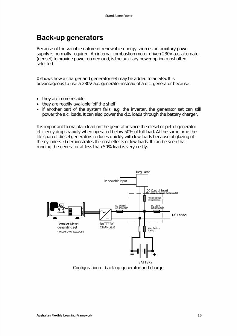
0 shows how a charger and generator set may be added to an SPS. It isadvantageous to use a 230V a.c. generator instead of a d.c. generator because :
• they are more reliable
• they are readily available ‘off the shelf ’• if another part of the system fails, e.g. the inverter, the generator set can still
power the a.c. loads. It can also power the d.c. loads through the battery charger.
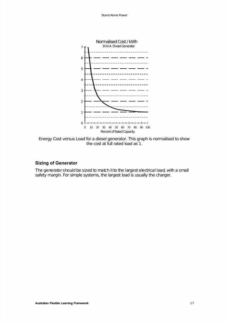
It is important to maintain load on the generator since the diesel or petrol generatorefficiency drops rapidly when operated below 50% of full load. At the same time thelife span of diesel generators reduces quickly with low loads because of glazing of the cylinders. 0 demonstrates the cost effects of low loads. It can be seen thatrunning the generator at less than 50% load is very costly.
Renewable Input
generating setPetrol or Diesel
( includes 240V output C/B )
BATTERYCHARGER
DC Load/s
Renewable I/Pcct protection
Main BatteryFusing
+
DC Loadcct protection
BATTERY
(Also includes meters, switches etc.)DC Control Board
cct protectionDC charger
Regulator
Configuration of back-up generator and charger
7/29/2019 Stand Alone Power
http://slidepdf.com/reader/full/stand-alone-power 20/28
Stand Alone Power
Australian Flexible Learning Framework 17
0
1
2
3
4
5
6
7
0 10 20 30 40 50 60 70 80 90 100
Normalised Cost / kWh8 kVA Diesel Generator
Percent of Rated Capacity Energy Cost versus Load for a diesel generator. This graph is normalised to show
the cost at full rated load as 1.
Sizing of Generator
The generator should be sized to match it to the largest electrical load, with a smallsafety margin. For simple systems, the largest load is usually the charger.
7/29/2019 Stand Alone Power
http://slidepdf.com/reader/full/stand-alone-power 21/28
Stand Alone Power
Australian Flexible Learning Framework 18
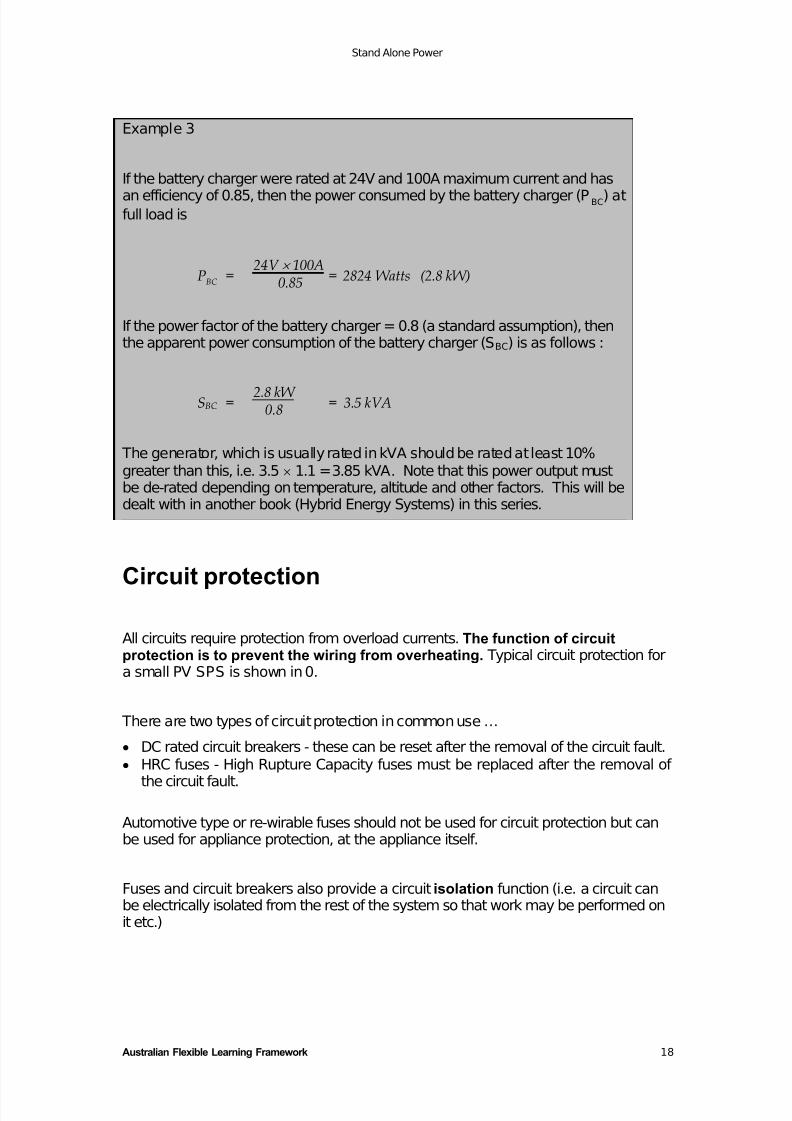
Example 3
If the battery charger were rated at 24V and 100A maximum current and has
an efficiency of 0.85, then the power consumed by the battery charger (P BC) atfull load is
PBC =24V × 100A
0.85 = 2824 Watts (2.8 kW)
If the power factor of the battery charger = 0.8 (a standard assumption), thenthe apparent power consumption of the battery charger (SBC) is as follows :
SBC = 2.8 kW 0.8 = 3.5 kVA
The generator, which is usually rated in kVA should be rated at least 10%greater than this, i.e. 3.5 × 1.1 = 3.85 kVA. Note that this power output mustbe de-rated depending on temperature, altitude and other factors. This will bedealt with in another book (Hybrid Energy Systems) in this series.
Circuit protection
All circuits require protection from overload currents. The function of circuitprotection is to prevent the wiring from overheating. Typical circuit protection fora small PV SPS is shown in 0.
There are two types of circuit protection in common use …
• DC rated circuit breakers - these can be reset after the removal of the circuit fault.
• HRC fuses - High Rupture Capacity fuses must be replaced after the removal of
the circuit fault.
Automotive type or re-wirable fuses should not be used for circuit protection but canbe used for appliance protection, at the appliance itself.
Fuses and circuit breakers also provide a circuit isolation function (i.e. a circuit canbe electrically isolated from the rest of the system so that work may be performed onit etc.)
7/29/2019 Stand Alone Power
http://slidepdf.com/reader/full/stand-alone-power 22/28
Stand Alone Power
Australian Flexible Learning Framework 19
Battery cable protection
HRC fuses are normally used because of the large current requirement of theinverter (in a typical system), and because they are capable of interrupting theenormous fault current that a battery can produce under short circuit. This fusing islocated as close as practicable to the battery to ensure that any unprotected cabling
is as short as possible.
Renewable input protection
A d.c. circuit breaker or HRC fuse is normally located in the control board, electricallybetween the regulator and the battery.
Battery charger protection
A d.c. circuit breaker or HRC fuse is normally located in the charger itself.
DC load Protection
A d.c. circuit breaker or HRC fuse is normally located in the control board. Wheremore than one d.c. circuit is used, each sub-circuit will have individual protection andall sub-circuits should be protected by a Main d.c. Load fuse or circuit breaker.
AC circuit protection
AC circuits in a SPS should be wired by a qualified person and protected to the samestandard as mains connected installations (AS 3000).
DC control board
The control board is normally the location of the majority of the system’s dc inter-connections. It also provides the logical mounting point for some of the circuitprotection (mentioned above), isolation switches (if used) and metering. The circuitprotection and isolation for the renewable power source and for the dc loads isnormally located here.
The minimum metering required is normally …
• an ammeter to indicate the output of the renewable energy source, and• a voltmeter showing battery voltage, which can give a rough indication of state of
charge
The other meter most often used is a load current ammeter to show the currentsupplied from the battery. Other equipment, such as a low voltage cutout or energyflow monitoring equipment can also be located at the control board.
7/29/2019 Stand Alone Power
http://slidepdf.com/reader/full/stand-alone-power 23/28
Stand Alone Power
Australian Flexible Learning Framework 20
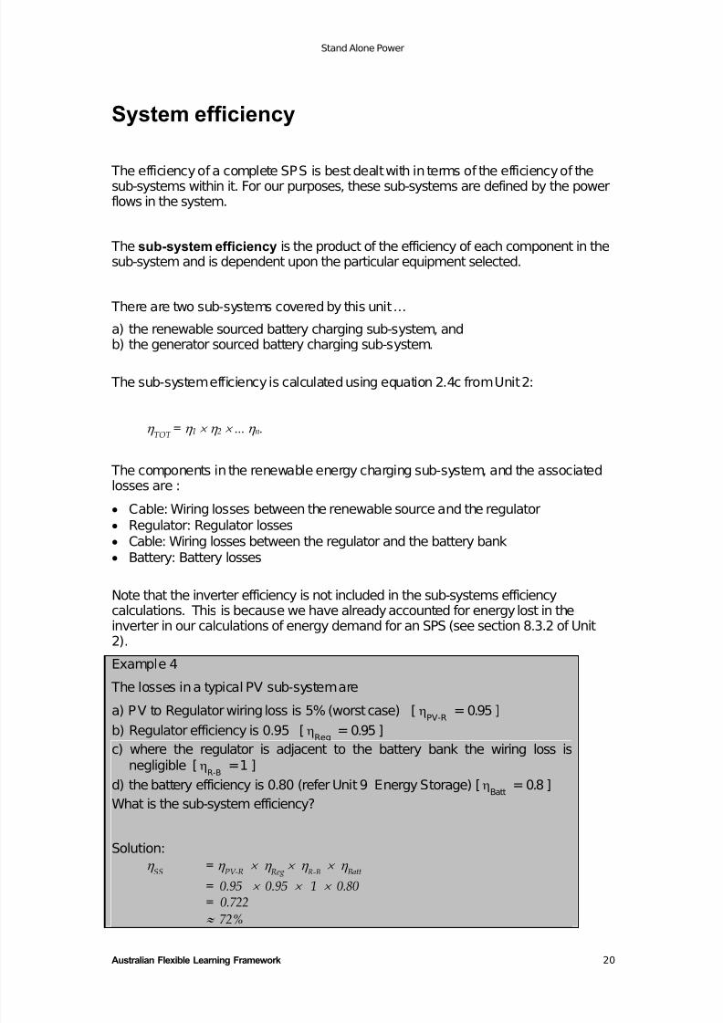
System efficiency
The efficiency of a complete SPS is best dealt with in terms of the efficiency of thesub-systems within it. For our purposes, these sub-systems are defined by the powerflows in the system.
The sub-system efficiency is the product of the efficiency of each component in thesub-system and is dependent upon the particular equipment selected.
There are two sub-systems covered by this unit …
a) the renewable sourced battery charging sub-system, andb) the generator sourced battery charging sub-system.
The sub-system efficiency is calculated using equation 2.4c from Unit 2:
η TOT = η 1 × η 2 × ... η n.
The components in the renewable energy charging sub-system, and the associatedlosses are :
• Cable: Wiring losses between the renewable source and the regulator
• Regulator: Regulator losses• Cable: Wiring losses between the regulator and the battery bank• Battery: Battery losses
Note that the inverter efficiency is not included in the sub-systems efficiencycalculations. This is because we have already accounted for energy lost in theinverter in our calculations of energy demand for an SPS (see section 8.3.2 of Unit2).
Example 4
The losses in a typical PV sub-system are
a) PV to Regulator wiring loss is 5% (worst case) [ηPV-R = 0.95 ]b) Regulator efficiency is 0.95 [η
Reg= 0.95 ]
c) where the regulator is adjacent to the battery bank the wiring loss isnegligible [η
R-B= 1 ]
d) the battery efficiency is 0.80 (refer Unit 9 Energy Storage) [ηBatt
= 0.8 ]
What is the sub-system efficiency?
Solution:
η SS = η
PV-R × η
Reg × η
R-B × η
Batt
= 0.95 × 0.95 × 1 × 0.80= 0.722
≈ 72%
7/29/2019 Stand Alone Power
http://slidepdf.com/reader/full/stand-alone-power 24/28
Stand Alone Power
Australian Flexible Learning Framework 21
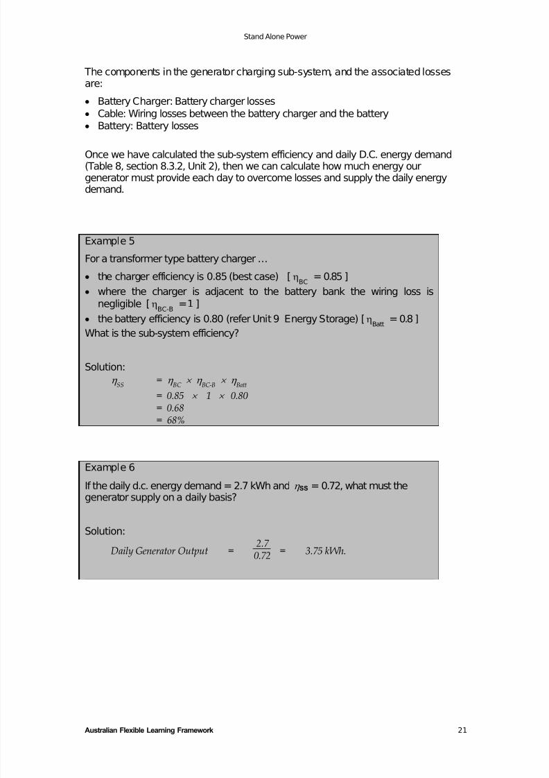
The components in the generator charging sub-system, and the associated lossesare:
• Battery Charger: Battery charger losses
• Cable: Wiring losses between the battery charger and the battery• Battery: Battery losses
Once we have calculated the sub-system efficiency and daily D.C. energy demand(Table 8, section 8.3.2, Unit 2), then we can calculate how much energy ourgenerator must provide each day to overcome losses and supply the daily energydemand.
Example 5
For a transformer type battery charger …
• the charger efficiency is 0.85 (best case) [ηBC = 0.85 ]
• where the charger is adjacent to the battery bank the wiring loss isnegligible [η
BC-B = 1 ]
• the battery efficiency is 0.80 (refer Unit 9 Energy Storage) [ηBatt = 0.8 ]
What is the sub-system efficiency?
Solution:
η SS = η
BC × η
BC-B × η
Batt
= 0.85 × 1 × 0.80
= 0.68= 68%
Example 6
If the daily d.c. energy demand = 2.7 kWh and η SS = 0.72, what must thegenerator supply on a daily basis?
Solution:
Daily Generator Output = 2.7 0.72 = 3.75 kWh.
7/29/2019 Stand Alone Power
http://slidepdf.com/reader/full/stand-alone-power 25/28
Stand Alone Power
Australian Flexible Learning Framework 22
Glossary
Term Description/Definition
add/shed regulators a PV regulator which disconnects parallel modules, orstrings of modules in steps to control the current flow intothe system
Array Ammeter measures the output current of the PV array
Battery Charger converts a.c. power from a generator to d.c. power suitablefor charging the system batteries
Battery Voltmeter measures the battery voltage - giving an approximateindication of the battery state of charge
Blocking Diode prevents reverse current flow to the generators
control board the location of the majority of the system’s dc inter-connections. It also provides the mounting point for someof the circuit protection, isolation switches and metering.
The circuit protection and isolation for the renewablepower source and for the dc loads is normally locatedhere.
DC bus the positive and negative terminals of the battery, powersources, and loads are all connected together. The “point”of common connection is called the d.c. bus. It often existsphysically as a terminal block with cables connected to it.
DC-DC converter an electronic device which converts dc power at one valueof voltage and current, and converts it to dc power atanother voltage and current. The power (product of voltageand current) remains the same, except for losses. It doesfor dc power what a transformer does for ac power.
Extra-Low Voltage Not exceeding or 50 V a.c. or 120 V d.c. ripple-free
ref AS3000 section 7.7 and AS 4509
Field controlregulator
A regulator which controls the voltage and current outputof rotating machines (alternators and dc generators) bycontrolling the magnetic field of the machine. The strengthof the magnetic field is varied by changing the field current.
harmonics parts of a waveform which actually have a frequency whichis some multiple of the fundamental waveform frequency.E.g. if the fundamental if 50 Hz, harmonics may exist at100 Hz, 150 Hz, 200 Hz, 250 Hz etc.
HRC Fuse High Rupture Capacity fuse, particularly good for d.c.currents. These fuses are capable of extinguishing the arcproduced when the fuse “blows”.
interactive inverter a true bi-directional device which can convert power, fromac to dc or vice versa, and can synchronize its ac outputwith a generator or other ac power source
7/29/2019 Stand Alone Power
http://slidepdf.com/reader/full/stand-alone-power 26/28
Stand Alone Power
Australian Flexible Learning Framework 23
Term Description/Definition
Inverter converts d.c. power to a.c. at 230 Volts, as required bystandard household appliances
inverter/charger houses an inverter and a battery charger in the same box
isolation a circuit can be electrically isolated from the rest of thesystem so that work may be performed on it etc.
Maximum Power Point Trackingregulator
a dc-dc converter which operates in such a way as toensure that the PV array operates at its maximum poweroutput under any conditions.
modified squarewave inverter
an inverter which produces a waveform like a squarewave, but with a delay period at zero volts between thetwo half cycles.
Regulator regulates/manages the flow of current to the battery tomaximise state of charge and extend battery life.
Self regulatingmodules
PV modules which have a lower open circuit voltage andknee voltage compared to the standard modules. Theyhave fewer cells than standard modules e.g. 33 instead of 36.
series regulator a regulator which uses a variable resistance element inseries with the battery to limit the current flow. A voltagesensor controls the resistance to control current flow
series switchedregulator
a regulator which disconnects the input when the batterybecomes fully charged.
shunt regulator a regulator which uses a current shunting element in
parallel with the input in order to dissipate excess powerfrom the source
sine wave inverter produces a waveform almost identical to the ideal “sinewave” over a wide range of loads
square waveinverter
the most simple form of inverter, which has a squareoutput voltage waveform
Stand-alone Power System (SPS).
a system which supplies electric power to a user, and isnot connected to the power distribution systems of anelectricity supply authority. Stand-alone power systems aresupplied with power from one or more of a number of
sources including but not limited to: a photovoltaic array, awind turbine generator, a micro-hydro generator or aengine generator set.
sub-systemefficiency
the product of the efficiency of each component In the sub-system, excluding the inverter.
VA Volt-Amps. This is a.c. apparent power, Volts x Amps.
7/29/2019 Stand Alone Power
http://slidepdf.com/reader/full/stand-alone-power 27/28
Stand Alone Power
Australian Flexible Learning Framework 24
Bibliography
Buresch, M.,(1983) Photovoltaic Energy Systems- Design and Installation. McGraw-Hill Book Company
Dunlop Batteries Australia, (1976) Dunlop Traction Batteries - Installation andMaintenance Manual Dunlop Australia Limited- Automotive and Industrial Group,Sandringham, Victoria.
Manders, J ., (1984) Lead-Acid Batteries For Remote Power Systems AustralianLead Development Association, Melbourne.
Paul, T., (1981) How To Design An Independent Power System Best EnergySystems For Tomorrow, Inc., USA.
Pedals, P (1993) Energy From Nature - A Complete Guide To IndependentEnergy Systems Rainbow Power Company , Nimbin, NSW , Australia.
Twidell, J ., & Weir, A., (1986) Renewable Energy Resources E & F.N. SponPublishers, London and New York.
Victorian Solar Energy Council (1989). Remote Area Power Supply VSEC:Melbourne.
7/29/2019 Stand Alone Power
http://slidepdf.com/reader/full/stand-alone-power 28/28
Stand Alone Power
For more information contact:
Australian Flexible Learning Framework
Phone: (07) 3307 4700
Fax: (07) 3259 4371
Email: [email protected]
Website: flexiblelearning.net.au
GPO Box 1326
Brisbane QLD 4001