Embed Size (px)
Citation preview

This installation guide demonstrate the basics on how to construct.
A) Segmental Concrete Gravity Retaining Walls up to 1060 mm high (Gravity). Page 2 to 5B) Segmental Concrete Reinforced Soil Retaining Walls over 1 metre high (Reinforced). Page 6 to 8C) Segmental Concrete Gravity Retaining Walls with No-fines Concrete over 1 metre high (No-fines Concrete). Page 9 to 11
This is a guide only, to help determine whether a gravity, soil reinforced or no-fines concrete retaining wall is the most appropriate for your situation, and the preparation necessary to achieve the end result.
This guide is not a design manual for soil reinforced or no-fines concrete retaining walls.The information provided in no way replaces the services of professional consultants on a particular project. No liability can therefore be accepted by DSM Masonry.
1. Wall Height: Determine the maximum wall height. (see figure1) Maximum Wall Height (figure 1) -
2. Decide On
A) Gravity retaining wall B) Soil reinforced retaining wallC) No-fines concrete retaining wallD) Segmental Concrete Gravity Retaining Wall.
DSM SENTINEL RETAINER ® ™Installation Guide
Tel: 011-9642995E-mail: [email protected]: www.dsmmasonry.co.za
FIG 1
WA
LL H
EIG
HT

DSM SENTINEL ® ™ Retainer Installation Guide
The recommended maximum height for straight SENTINEL retaining walls is 860mm (three courses and cap) and serpentine SENTINEL retaining walls is 1060 mm (five courses and cap).
SENTINEL walls intended to support higher embankments must comply with CMA Code of Practice for “Earth retaining structures” and the advice of a competent civil engineer should be sought.
The following limitations comply with the requirements of Concrete Masonry Association Code of Practice for Gravity Walls Manual “Segmental Concrete Gravity Retaining Walls. This design may be used to determine the permissible height of retaining walls satisfying the following criteria. For retaining walls outside these criteria, the design shall be determined using engineering analysis similar to that shown in the worked example, Appendix A, by qualified and experienced civil or structural engineers with a comprehensive working knowledge of soil mechanics and structural analysis and design.
Details of the Sentinel System
Block height 200 mm (plus 10 mm tab height)
Block length 390 mm
Block depth (into the embankment) 225 mm
Block weight 23.5 kg
Capping block weight 12 kg
Setback distance per block 10 mm
Wall slope 3 degrees (10 in 225)
Infill behind and within the facing blocks Compacted 10 to 20 mm crushed rock aggregate
Bearing pad Compacted 10 to 20 mm crushed rock aggregate
Drainage pipe 100 mm diameter PVC agricultural pipe with sock
Sentinel Curved and Serpentine Gravity Retaining Walls up to 1060 mm High -
TOPSOIL
TOPSOIL
100Ø PERFORATED DRAINCOIL SLOPE 1:80 AND CONNECT TO STORMWATER SYSTEM
FILTER FABRIC
SENTINEL RETAINER
BLOCK BEDDING SAND
FREE-DRAINING GRANULAR BACKFILL
400 X 200 DEEP COMPACTED HARDFILL
1
20
SENTINEL RETAINER CAPPING
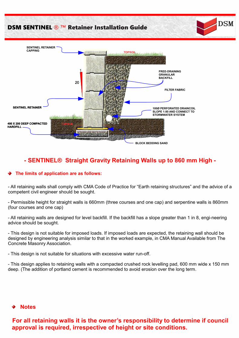
- SENTINEL® Straight Gravity Retaining Walls up to 860 mm High -
The limits of application are as follows:
- All retaining walls shall comply with CMA Code of Practice for “Earth retaining structures” and the advice of a competent civil engineer should be sought.
- Permissible height for straight walls is 660mm (three courses and one cap) and serpentine walls is 860mm (four courses and one cap)
- All retaining walls are designed for level backfill. If the backfill has a slope greater than 1 in 8, engineering advice should be sought.
- This design is not suitable for imposed loads. If imposed loads are expected, the retaining wall should be designed by engineering analysis similar to that in the worked example, in CMA Manual Available from The Concrete Masonry Association.
- This design is not suitable for situations with excessive water run-off.
- This design applies to retaining walls with a compacted crushed rock levelling pad, 600 mm wide x 150 mm deep. (The addition of portland cement is recommended to avoid erosion over the long term.
Notes
For all retaining walls it is the owner’s responsibility to determine if council approval is required, irrespective of height or site conditions.
100Ø PERFORATED DRAINCOIL SLOPE 1:80 AND CONNECT TO STORMWATER SYSTEM
SENTINEL RETAINER
400 X 200 DEEP COMPACTED HARDFILL
TOPSOIL
TOPSOIL
1
20
SENTINEL RETAINER CAPPING
SENTINEL RETAINER
400 X 200 DEEP COMPACTED HARDFILL
20
FILTER FABRIC
FREE-DRAINING GRANULAR BACKFILL
BLOCK BEDDING SAND
DSM SENTINEL ® ™ Retainer Installation Guide

Installing Segmental Concrete Gravity Retaining Walls
Step 1 - Check with your local council to ensure all local Building Codes are complied with.
Step 2 - FoundationThe foundation material shall be compacted by several passes of a mechanical plate vibrator. Where there are significant variations of foundation material or compaction, soft spots, or where there is ponding of ground water, the material shall be removed, replaced and compacted in layers not exceeding 150 mm. Trenches shall be dewatered and cleaned prior to construction, such that no softened or loosened material remains.
Step 3 - Bearing PadThe facing shall be built on a bearing pad, not less than 150 mm thick, consisting of one of the following options:●Compacted crushed rock, well-graded and of low plasticity (without clay content), compacted by a plate vibrator;
• Cement-stabilized crushed rock, with an additional 5% by mass of GP Portland cement thoroughly mixed, moistened and compacted by a plate vibrator; or
• Lean-mix concrete with a compressive strength of not less than 15 MPa.
Step 4 - First CourseSpread 25mm of metal dust with an additional 5% by mass of GP Portland cement over the compacted base.The first course is now bedded into the metal dust. The use of a level and string line is recommended to ensure the first course is laid correctly Ensure each block is also well filled with free-draining material. (eg crushed rock aggregate / blue metal).
Step 5 - Drainage and BackfillPlace 100 mm diameter PVC agricultural pipe with sock behind the wall, with a 1 in 100 fall. Backfill behind the courses of blocks to a width of approx. 200mm - 300mm using 10 - 20 mm free draining material (eg crushed rock aggregate / blue metal). Ensure each block is also well filled with free-draining material.
DSM SENTINEL ® ™ Retainer Installation Guide
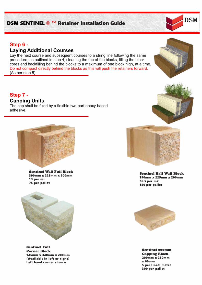
Step 6 - Laying Additional CoursesLay the next course and subsequent courses to a string line following the same procedure, as outlined in step 4, cleaning the top of the blocks, filling the block cores and backfilling behind the blocks to a maximum of one block high, at a time. Do not compact directly behind the blocks as this will push the retainers forward.(As per step 5)
Step 7 - Capping UnitsThe cap shall be fixed by a flexible two-part epoxy-basedadhesive.
DSM SENTINEL ® ™ Retainer Installation Guide
Sentinel FullCorner Block145mm x 340mm x 200mm(Available in left or r ight)Left hand corner show n
Sentinel Wall Full Block390mm x 225mm x 200mm1 3 per m2
75 per pallet
Sentinel Half Wall Block190mm x 225mm x 200mm26.5 per m2150 per pallet
Sentinel 200mmCapping Block200mm x 280mm x 60mm5 per lineal metre300 per pallet
DSM SENTINEL ® ™ Retainer Installation Guide
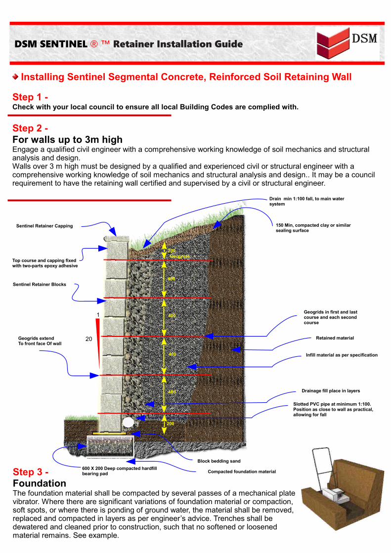
Installing Sentinel Segmental Concrete, Reinforced Soil Retaining Wall
Step 1 - Check with your local council to ensure all local Building Codes are complied with.
Step 2 - For walls up to 3m highEngage a qualified civil engineer with a comprehensive working knowledge of soil mechanics and structural analysis and design. Walls over 3 m high must be designed by a qualified and experienced civil or structural engineer with a comprehensive working knowledge of soil mechanics and structural analysis and design.. It may be a council requirement to have the retaining wall certified and supervised by a civil or structural engineer.
Step 3 - FoundationThe foundation material shall be compacted by several passes of a mechanical plate vibrator. Where there are significant variations of foundation material or compaction, soft spots, or where there is ponding of ground water, the material shall be removed, replaced and compacted in layers as per engineer’s advice. Trenches shall be dewatered and cleaned prior to construction, such that no softened or loosened material remains. See example.
Compacted foundation material600 X 200 Deep compacted hardfill bearing pad
Slotted PVC pipe at minimum 1:100. Position as close to wall as practical, allowing for fall
Block bedding sand
Retained material
Sentinel Retainer Capping
1
20Geogrids extendTo front face Of wall
Geogrids
Sentinel Retainer Blocks
200
Drain min 1:100 fall, to main water system
400
Drainage fill place in layers
Infill material as per specification
Geogrids in first and last course and each second course
150 Min, compacted clay or similar sealing surface
200
400
400
400
Top course and capping fixed with two-parts epoxy adhesive

Step 4 - Bearing PadThe facing shall be built on a bearing pad, as per engineers advice, consisting of one of the following options:
Compacted crushed rock, well-graded and of low plasticity
(without clay content), compacted by a plate vibrator; Cement-stabilized crushed rock, with an additional 5% by mass of GP Portland
cement thoroughly mixed, moistened and compacted by a plate vibrator; or Lean-mix concrete with a compressive strength of not less than 15 MPa.
Step 5 - Drainage, Backfill and the First Course of SENTINEL RetainerEnsure the first course is embedded below the finished ground level.Place 100 mm diameter PVC agricultural pipe with sock behind the wall, with a 1 in 100 fall. The agricultural pipe should be connected to a PVC stormwater pipe and brought through the front of the wall at intervals not exceeding 30m. It should be connected to a PVC stormwater system at the lower end of each run, where practical, and must drain positively away from the base of the retaining wall.Backfill behind the courses of blocks to a width of not less than 300mm using 10-20 mm free draining material (eg crushed rockaggregate / blue metal). Ensure each block is also well filled withfree-draining material. Back fill behind the drainage layer with the specified backfill in a maximum of 200mm layers.Compaction rate of 95% must be achieved (use only hand operated plate compactors close to the wall). Soft or wet clay must not be used to backfill. The use of a level and string line is recommended to ensure the first course is laid correctly.
Step 6 - Laying GeogridClean any debris from the top of the block wall to ensure the next block and or the geogrid layer sits perfectly. Roll the geogridperpendicular to the wall, pull tight, stake in place and cut to therequired length. Ensure that the geogrid sits within 15mm of the face of the block, so that the purpose made connecting lugs caninterlock. Butt join the geogrid along the length of the wall. Place the next course on top of the geogrid.
DSM SENTINEL ® ™ Retainer Installation Guide

DSM SENTINEL ® ™ Retainer Installation Guide
2.5 M
Note: Geogrid Is stronger in the longer direction.
GEOGRID ROLL LENGTH SHOULD
BE PLACED PERPENDICULAR TO
THE WALL FACE
DSM SENTINEL®
RETAINER
Step 7 - Laying Additional CoursesLay the next course and subsequent courses to a string linefollowing the procedures outlined previously i.e. Clean any debris from the top of the block wall to ensure the next block and or the geogrid layer sits perfectly. Backfill behind the course of blocks to a width of not less than 300mm using 10-20 mm free draining material (eg crushed rock aggregate / blue metal). Ensure each block is also well filled with free-draining material.Back fill behind the drainage layer with the specified backfill in a maximum of 200mm layers.Compaction rate of 95% must be achieved (use only hand operated plate compactors close to the wall). Soft or wet clay must not be used to backfill.Do not compact directly behind the blocks as this will push the retainers forward
Step 8 - CappingThe capping block shall be fixed by a flexible two-part epoxy-based adhesive
Step 9 - Surface DrainageThe whole of the disturbed fill surface should be sealed by at least 150mm of compacted clay and properly drained. Alternative means, such as bentonite layers or PVC membranes may be employed, provided they do not introduce potential slip planes into the surface material.
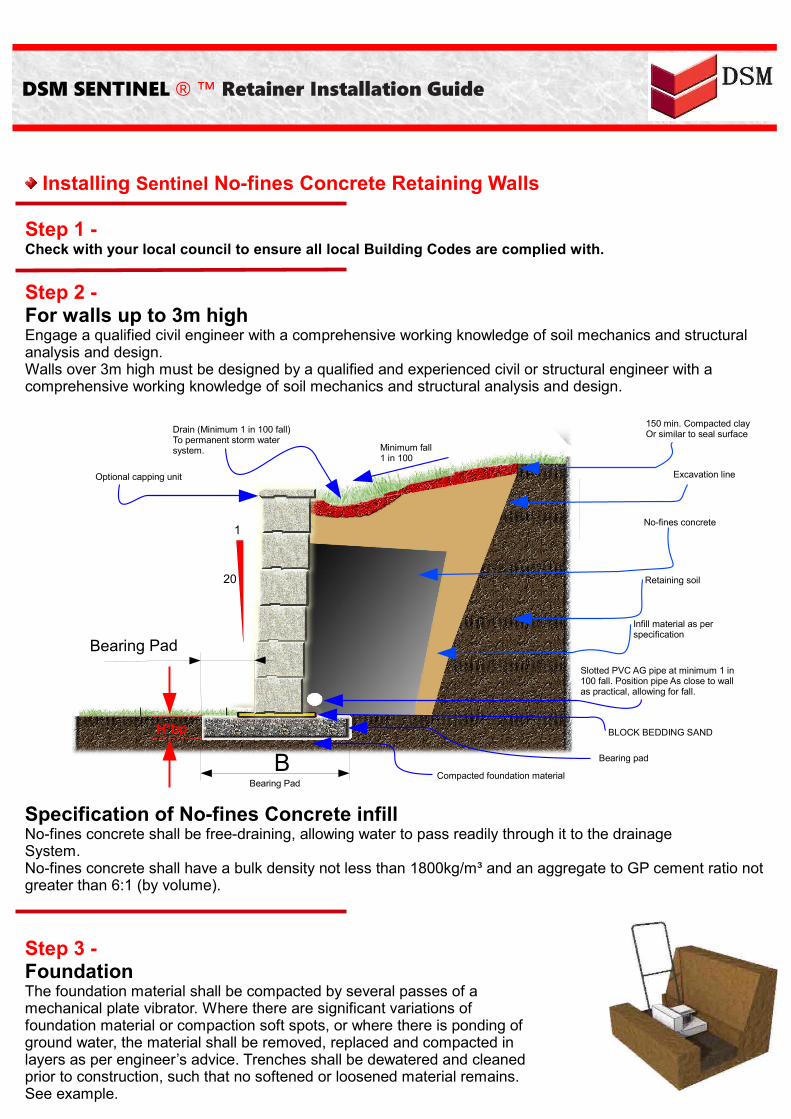
Installing Sentinel No-fines Concrete Retaining Walls
Step 1 - Check with your local council to ensure all local Building Codes are complied with.
Step 2 - For walls up to 3m highEngage a qualified civil engineer with a comprehensive working knowledge of soil mechanics and structural analysis and design. Walls over 3m high must be designed by a qualified and experienced civil or structural engineer with a comprehensive working knowledge of soil mechanics and structural analysis and design.
DSM SENTINEL ® ™ Retainer Installation Guide
Specification of No-fines Concrete infillNo-fines concrete shall be free-draining, allowing water to pass readily through it to the drainageSystem.No-fines concrete shall have a bulk density not less than 1800kg/m³ and an aggregate to GP cement ratio not greater than 6:1 (by volume).
Step 3 - FoundationThe foundation material shall be compacted by several passes of a mechanical plate vibrator. Where there are significant variations of foundation material or compaction soft spots, or where there is ponding of ground water, the material shall be removed, replaced and compacted in layers as per engineer’s advice. Trenches shall be dewatered and cleaned prior to construction, such that no softened or loosened material remains. See example.
Excavation line
No-fines concrete
Retaining soil
Infill material as per specification
Slotted PVC AG pipe at minimum 1 in 100 fall. Position pipe As close to wall as practical, allowing for fall.
Compacted foundation materialBearing Pad
Bearing padB
150 min. Compacted clayOr similar to seal surface
1
20
H*bp
Bearing Pad
Drain (Minimum 1 in 100 fall)To permanent storm water system.
Optional capping unit
Minimum fall1 in 100
BLOCK BEDDING SAND

Step 4 - Bearing PadThe facing shall be built on a bearing pad, as per engineers advice, consisting of one of the following options:
Compacted crushed rock, well-graded and of low plasticity (without clay content), compacted by a plate vibrator.
Cement-stabilized crushed rock, with an additional 5% by mass of GP Portland cement thoroughly mixed, moistened and compacted by a plate vibrator; or
Lean-mix concrete with a compressive strength of not less than 15 MPa.
DSM SENTINEL ® ™ Retainer Installation Guide
Step 5 - Drainage, Backfill and the First Course of SENTINEL®Place 100 mm diameter PVC agricultural pipe with sock behind the wall, with a 1 in 100 fall. The agricultural pipe should be connected to a PVC stormwater pipe and brought through the front of the wall at intervals not exceeding 30m. It should be connected to a PVC stormwater system at the lower end of each run, where practical, and must drain positively away from the base of the retaining wall.Backfill behind the course of blocks to a width of not less than 300mm using no-fines concrete. Ensure each block is also well filled with no-fines concrete. Back fill behind the drainage layer with the specified backfill in a maximum of 200mm layers.Compaction rate of 95% must be achieved (use only hand operated plate compactors close to the wall). Soft or wet clay must not be used to backfill. The use of a level and string line is recommended to ensure the first course is laid correctly.
Step 6 - Laying Additional CoursesLay the next course and subsequent courses to a string linefollowing the procedures outlined previously i.e. Clean any debris from the top of the block wall to ensure the next block sits perfectly. Backfill behind the course of blocks to a width of not less than 300mm using no-fines concrete. Ensure each block is also well filled with no-fines concrete.Back fill behind the drainage layer with the specified backfill in amaximum of 200mm layers.Compaction rate of 95% must be achieved (use only hand operated plate compactors close to the wall). Soft or wet clay must not be used to backfill.Do not compact directly behind the blocks as this will push the retainers forward

Step 7 - For CappingThe capping block shall be fixed by a flexible two-part epoxy-based adhesive
DSM SENTINEL ® ™ Retainer Installation Guide
Step 8 - Surface DrainageThe whole of the disturbed fill surface should be sealed by at least 150mm of compacted clay and properly drained. Alternative means such as bentonite layers or PVC membranes may be employed,provided they do not introduce potential slip planes into the surface material.
Corners
SENTINEL corners are built by fixing the purpose made corner blocks alternately to each course using adhesive. Allowances should be made for a 10mm step back per course.Lugs must be removed from the SENTINEL Blocks to ensure that the corner block fits evenly.A maximum height of one metre is recommended when using corner blocks.Curved corners is the preferred method of corner construction.
First Course Additional Courses Capping

DSM SENTINEL ® ™ Retainer Installation Guide
Curves
Curves and serpentine walls are easy to construct and the best guide is to lay out a garden hose and follow the profile. Be conscious that the length of courses will vary for a concave or convex wall. With fewer blocks per lineal metre of a convex, and more blocks per lineal metre when the wall isconcave. For convex curved walls knock the back fin off the block with a hammer. For concave walls simply position blocks. The minimum radius for the top course of SENTINEL half blocks is 650mm and SENTINEL blocks is 1300mm. Adjust lower courses allowing for 10mm step back. Always keep the front of the blocks tightly together.
First Course Additional Courses Capping
Steps
Steps must be built according to the local building code, so always check with your local building authority for the minimum requirements before commencing.
Prepare Surface Install Blocks Capping

DSM SENTINEL ® ™ Retainer Installation Guide
Internal Corner Caps - Cutting Detail
Cut Line
Finished Corner Cut Line
Finished Corner
External Corner Caps - Cutting Detail
DSM SENTINEL ® ™ Retainer Installation Guide
Glossary
Gravity Retaining WallsGravity retaining walls depend on the weight of their mass to resist pressures from behind and will often have a slight batter set back, to improve stability by leaning back into the retained soil.
Soil Reinforced Retaining WallsSoil reinforced retaining walls incorporate geogrids into the soil structure to create a segmental concrete reinforced soil structure. Such systems can be constructed several metres high and accommodate significant loads.
No-Fines Concrete Retaining WallNo-fines concrete retaining walls use no-fines concrete as a mass behind the concrete facing units to reinforce the soil structure to create a segmental concrete reinforced soil structure. Such systems can be constructed several metres high and accommodate signifcant loads.
Serpentine WallThe serpentine wall derives its name from its curving shape, which is in the form of a snake.
GeogridsLayers of metal or plastic material, which when constructed in horizontal planes in a soil mass, strengthen the soil. The most common geogrids are open “mesh” consisting of polyester, high-density polyethene, polyproplene or steel.
Infill MaterialThe soil material, placed behind the retaining wall facing and strengthened by the geogrids.
FoundationThe natural soil or rock material under a retaining wall.
Bearing PadThe pad the SENTINEL blocks are built on.
Drainage FillThe crushed rock, gravel or similar material placed behind a retaining wall to convey groundwater away from the wall foundations. It is commonly used in conjunction with other drainage media, such as agricultural pipes.
DSM SENTINEL RETAINER ® ™Installation Guide
Tel: 011-9642995E-mail: [email protected]: www.dsmmasonry.co.za