Embed Size (px)
Citation preview

BASICS AND INSTALLATIONRFID
2 | RFID
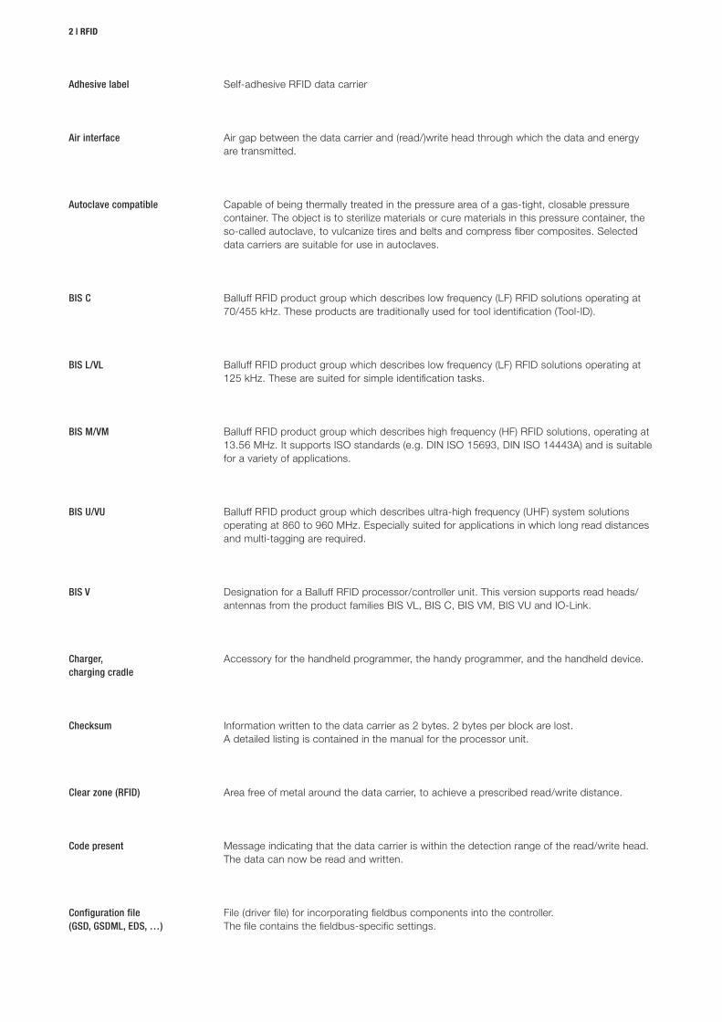
Capable of being thermally treated in the pressure area of a gas-tight, closable pressure container. The object is to sterilize materials or cure materials in this pressure container, the so-called autoclave, to vulcanize tires and belts and compress fiber composites. Selected data carriers are suitable for use in autoclaves.
Autoclave compatible
Balluff RFID product group which describes low frequency (LF) RFID solutions operating at 70/455 kHz. These products are traditionally used for tool identification (Tool-ID).
BIS C
Balluff RFID product group which describes low frequency (LF) RFID solutions operating at 125 kHz. These are suited for simple identification tasks.
BIS L/VL
Balluff RFID product group which describes high frequency (HF) RFID solutions, operating at 13.56 MHz. It supports ISO standards (e.g. DIN ISO 15693, DIN ISO 14443A) and is suitable for a variety of applications.
BIS M/VM
Balluff RFID product group which describes ultra-high frequency (UHF) system solutions operating at 860 to 960 MHz. Especially suited for applications in which long read distances and multi-tagging are required.
BIS U/VU
Designation for a Balluff RFID processor/controller unit. This version supports read heads/ antennas from the product families BIS VL, BIS C, BIS VM, BIS VU and IO-Link.
BIS V
Message indicating that the data carrier is within the detection range of the read/write head. The data can now be read and written.
Code present
Area free of metal around the data carrier, to achieve a prescribed read/write distance. Clear zone (RFID)
File (driver file) for incorporating fieldbus components into the controller. The file contains the fieldbus-specific settings.
Configuration file (GSD, GSDML, EDS, …)
Accessory for the handheld programmer, the handy programmer, and the handheld device.Charger,charging cradle
Information written to the data carrier as 2 bytes. 2 bytes per block are lost. A detailed listing is contained in the manual for the processor unit.
Checksum
Self-adhesive RFID data carrierAdhesive label
Air gap between the data carrier and (read/)write head through which the data and energy are transmitted.
Air interface
www.balluff.com
Basics and installation | 3
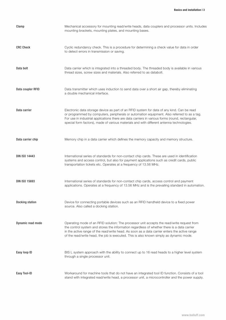
Cyclic redundancy check. This is a procedure for determining a check value for data in order to detect errors in transmission or saving.
CRC Check
Data transmitter which uses induction to send data over a short air gap, thereby eliminating a double mechanical interface.
Data coupler RFID
Data bolt Data carrier which is integrated into a threaded body. The threaded body is available in various thread sizes, screw sizes and materials. Also referred to as databolt.
Electronic data storage device as part of an RFID system for data of any kind. Can be read or programmed by computers, peripherals or automation equipment. Also referred to as a tag. For use in industrial applications there are data carriers in various forms (round, rectangular, special form factors), made of various materials and with different antenna technologies.
Data carrier
Memory chip in a data carrier which defines the memory capacity and memory structure.Data carrier chip
International series of standards for non-contact chip cards. These are used in identification systems and access control, but also for payment applications such as credit cards, public transportation tickets etc. Operates at a frequency of 13.56 MHz.
DIN ISO 14443
International series of standards for non-contact chip cards, access control and payment applications. Operates at a frequency of 13.56 MHz and is the prevailing standard in automation.
DIN ISO 15693
Device for connecting portable devices such as an RFID handheld device to a fixed power source. Also called a docking station.
Docking station
Operating mode of an RFID solution: The processor unit accepts the read/write request from the control system and stores the information regardless of whether there is a data carrier in the active range of the read/write head. As soon as a data carrier enters the active range of the read/write head, the job is executed. This is also known simply as dynamic mode.
Dynamic read mode
BIS L system approach with the ability to connect up to 16 read heads to a higher level system through a single processor unit.
Easy loop ID
Workaround for machine tools that do not have an integrated tool ID function. Consists of a tool stand with integrated read/write head, a processor unit, a microcontroller and the power supply.
Easy Tool-ID
Mechanical accessory for mounting read/write heads, data couplers and processor units. Includes mounting brackets, mounting plates, and mounting bases.
Clamp
4 | RFID
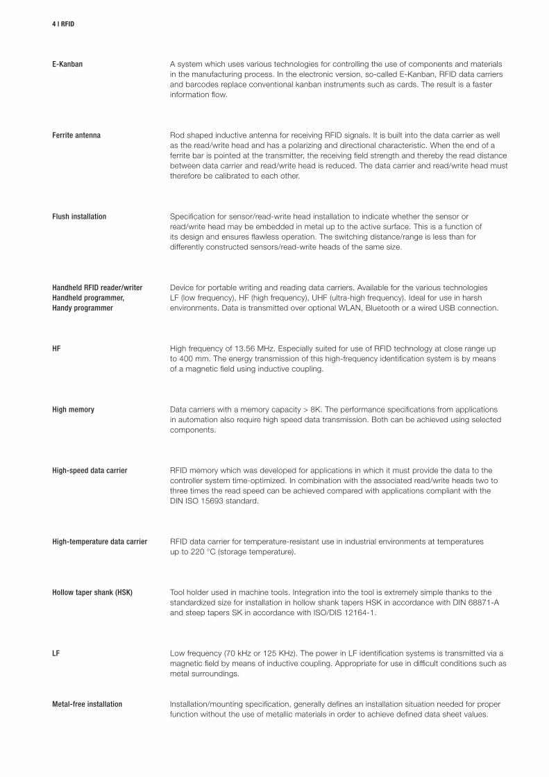
Rod shaped inductive antenna for receiving RFID signals. It is built into the data carrier as well as the read/write head and has a polarizing and directional characteristic. When the end of a ferrite bar is pointed at the transmitter, the receiving field strength and thereby the read distance between data carrier and read/write head is reduced. The data carrier and read/write head must therefore be calibrated to each other.
Ferrite antenna
Device for portable writing and reading data carriers. Available for the various technologies LF (low frequency), HF (high frequency), UHF (ultra-high frequency). Ideal for use in harsh environments. Data is transmitted over optional WLAN, Bluetooth or a wired USB connection.
Handheld RFID reader/writerHandheld programmer,Handy programmer
High frequency of 13.56 MHz. Especially suited for use of RFID technology at close range up to 400 mm. The energy transmission of this high-frequency identification system is by means of a magnetic field using inductive coupling.
HF
Data carriers with a memory capacity > 8K. The performance specifications from applications in automation also require high speed data transmission. Both can be achieved using selected components.
High memory
RFID memory which was developed for applications in which it must provide the data to the controller system time-optimized. In combination with the associated read/write heads two to three times the read speed can be achieved compared with applications compliant with the DIN ISO 15693 standard.
High-speed data carrier
RFID data carrier for temperature-resistant use in industrial environments at temperatures up to 220 °C (storage temperature).
High-temperature data carrier
Tool holder used in machine tools. Integration into the tool is extremely simple thanks to the standardized size for installation in hollow shank tapers HSK in accordance with DIN 68871-A and steep tapers SK in accordance with ISO/DIS 12164-1.
Hollow taper shank (HSK)
Low frequency (70 kHz or 125 KHz). The power in LF identification systems is transmitted via a magnetic field by means of inductive coupling. Appropriate for use in difficult conditions such as metal surroundings.
LF
Installation/mounting specification, generally defines an installation situation needed for proper function without the use of metallic materials in order to achieve defined data sheet values.
Metal-free installation
Specification for sensor/read-write head installation to indicate whether the sensor or read/write head may be embedded in metal up to the active surface. This is a function of its design and ensures flawless operation. The switching distance/range is less than for differently constructed sensors/read-write heads of the same size.
Flush installation
A system which uses various technologies for controlling the use of components and materials in the manufacturing process. In the electronic version, so-called E-Kanban, RFID data carriers and barcodes replace conventional kanban instruments such as cards. The result is a faster information flow.
E-Kanban
www.balluff.com
Basics and installation | 5
The part of an RFID system that supplies the data carrier with power and reads the data stored on it. The read head then passes the data to a processor unit which further processes the data.
Read head
World's most often used contactless chip card technology. Complies with ISO-Standards ISO 7816 and ISO 14443A.
Mifare
System solution for automated managing of injection molding tools in the plastics industry.Mold ID
Mechanical accessory for mounting read/write heads, data couplers and processor units. Examples are clamping holders or mounting brackets.
Mounting bracket/base/plate
Near field communication: An international transmission standard based on RFID for contactless exchange of data using electromagnetic induction and loosely coupled coils over short distances of a few centimeters and a data transfer rate of maximum 424 kBit/s.
NFC
Specification for installing sensors or read/write heads which do not have a metal housing surrounding their sensing face. These can be recognized by their "caps". This design ensure flawless sensor function. The switching distance/range and permissible offset are greater than for flush mount sensors or read/write heads of the same size.
Non-flush mounting
Accessory for the handheld programmer, the handy programmer, and the handheld device.Pistol grip
Essential component of an RFID system which is used for signal processing and preparation. Usually used or combined with an integrated interface for connecting to the controller/ PC system. It is also referred to as a controller.
Processor unit
Positioning tolerance between the read/write head and the data carrierOffset
In processor units connecting multiple read/write heads the process data buffer is divided into read/write head-specific areas. Process data is the data which is obtained from a technical process by means of a read/write head. The process data represents the current status.
Process data buffer
Memory chip in a data carrier which defines the memory capacity and memory structure.Reader chip
Part of an RFID system that supplies the data carrier with power and reads the data stored on it and stores new data. The read head then passes the data to a processor unit which further processes the data.
Read/write head
Time a data carrier requires for detecting/transmitting data. Comprised of: Data carrier detection + read/write time of the data blocks taken together. The read/write time varies with the data carrier type (FRAM, EEPROM) and the transmission standard.
Read/write time data carrier
6 | RFID
Connection point for various devices. For service purposes it sends device-specific setting data and is not suitable or standardized as a process interface.
Service interface
Multiple read/write heads are read by a processor unit (controller) simultaneously.Simultaneous operation
Data carrier detection whereby the antenna on the read/write head is switched on for detection only every 200 ms.
Slow tag detection
Mode of operation of an RFID system. The data carrier remains in place in front of the read/write head. This enables a greater read/write distance than in dynamic mode.
Static read mode
Standardized form of a tool holder for clamping various tools in the main spindle of a machine tool. The taper is standardized in DIN ISO 7388 Part 1. The main field of application is in milling machines.
Taper (SK)
Special solution approach for systematic wiring and for operating multiple read/write heads with a gateway component.
Subnet 16
Electronic data storage device used as part of an RFID system for data of any kind. Can be read or programmed by computers, peripherals or automation equipment. For use in industrial applications there are data carriers in various forms (round, rectangular, special form factors), made of various materials and with different antenna technologies. Also referred to as a data carrier.
Tag
Radio frequency identification: Communication technology for non-contact and automatic identification of objects (including merchandise, goods, people, animals using radio waves).
RFID
Electronic data storage medium as part of an RFID system. It can be read and, in specific configurations, also written. Also called a transponder.
RFID data carriers
Device for receiving RFID signals. In contrast to the bar/ferrite antenna it has no polarizing or directional effect. The electrostatic lobe is distributed evenly around the antenna. The round antenna is used both in data carriers and in the read/write head. Therefore these need to be tuned to each other.
Round antenna
Rod shaped inductive antenna for receiving RFID signals (ferrite antenna). It is built into the data carrier as well as the read/write head and has a polarizing and directional characteristic. When the end of a ferrite bar is pointed at the transmitter, the receiving field strength and thereby the read distance between data carrier and read/write head is reduced. The data carrier and read/write head must therefore be calibrated to each other
Rod antenna
www.balluff.com
Basics and installation | 7
Identification of tools and tool data for automated detection, traceability of tool data in the area of machine tools. Data carriers and read/write heads are generally installed in metallic surroundings. The requirements for read distance and installation conditions are generally high.
Tool ID
Unique identifier for RFID data carriers. Each number is assigned only once.UID
Ultra high frequency (865 to 960 MHz). The power transmission in UHF identification systems takes place by means of electromagnetic waves as in the classic radio systems. Appropriate for use over larger distances (several meters).
UHF
Identification of workpieces, semi- and finished products or workpiece carriers. The require-ments vary depending on the materials used. Compared with tool identification the requirements for read distance are generally low to moderate. "Dynamic reading" operating mode is often used.
Workpiece identification
8 | RFID
Mounting
Mounting in steel
RFID SYSTEMS HF (13.56 MHZ) BIS MRFID SYSTEMS LF (70/455 KHZ) BIS CRFID SYSTEMS LF (125 KHZ) BIS L
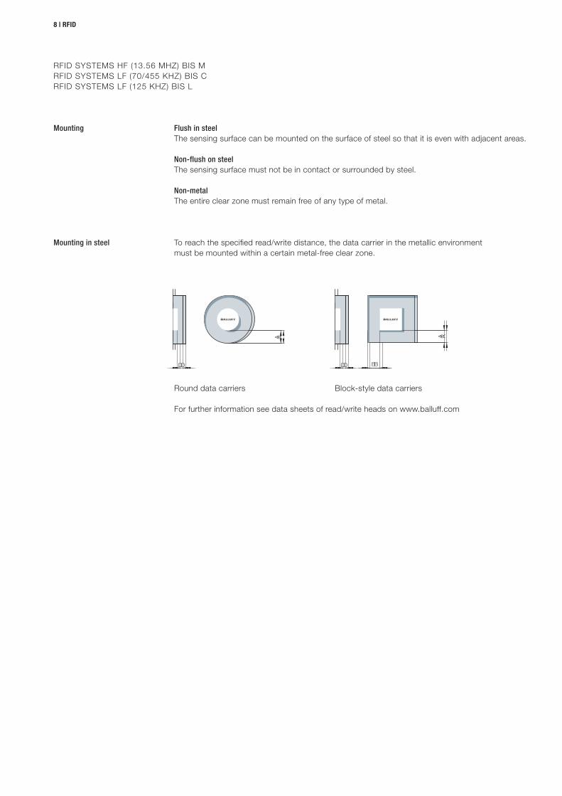
To reach the specified read/write distance, the data carrier in the metallic environment must be mounted within a certain metal-free clear zone.
For further information see data sheets of read/write heads on www.balluff.com
Round data carriers Block-style data carriers
Flush in steelThe sensing surface can be mounted on the surface of steel so that it is even with adjacent areas.
Non-flush on steelThe sensing surface must not be in contact or surrounded by steel.
Non-metalThe entire clear zone must remain free of any type of metal.
A
B
A
B
www.balluff.com
Basics and installation | 9
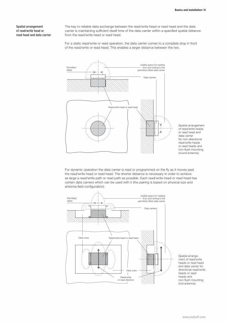
Spatial arrangement of read/write head or read head and data carrier
The key to reliable data exchange between the read/write head or read head and the data carrier is maintaining sufficient dwell time of the data carrier within a specified spatial distance from the read/write head or read head.
For a static read/write or read operation, the data carrier comes to a complete stop in front of the read/write or read head; This enables a larger distance between the two.
Spatial arrangement of read/write heads or read head and data carrier for non-directional read/write heads or read heads and non-flush mounting (round antenna).
Data carriers
Usable space for reading from and writing to the
permitted offset data carrierPermitted offset
Read/write head or read head
Spatial arrange-ment of read/write heads or read head and data carrier for directional read/write heads or read heads and non-flush mounting (rod antenna).
Usable space for reading from and writing to the
permitted offset data carrier
Data carriers
Clear zone
Clear zone
Read/write head or read head
Read/write or read direction
Permitted offset
For dynamic operation the data carrier is read or programmed on the fly as it moves past the read/write head or read head. The shorter distance is necessary in order to achieve as large a read/write path or read path as possible. Each read/write head or read head has certain data carriers which can be used with it (the pairing is based on physical size and antenna field configuration).
10 | RFID
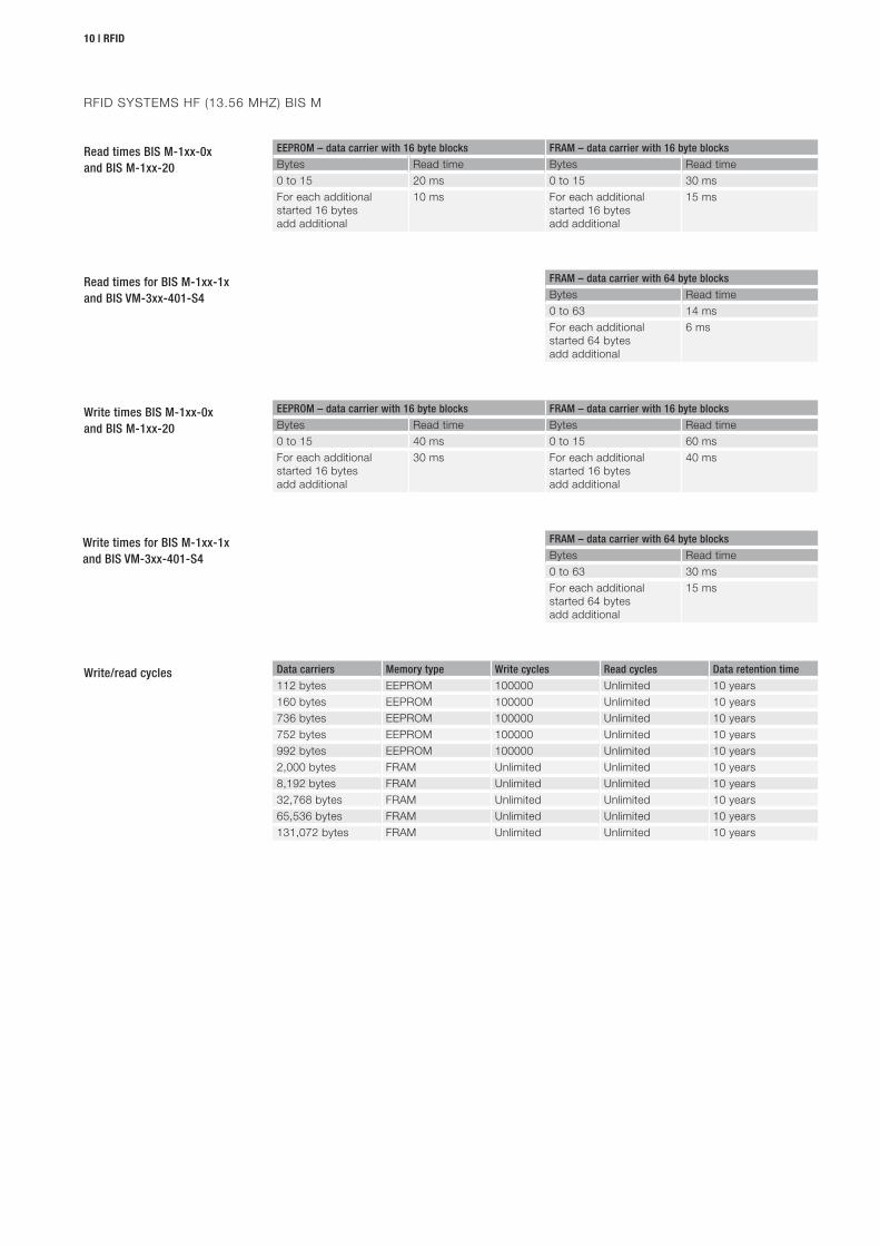
Write/read cycles Data carriers Memory type Write cycles Read cycles Data retention time
112 bytes EEPROM 100000 Unlimited 10 years160 bytes EEPROM 100000 Unlimited 10 years736 bytes EEPROM 100000 Unlimited 10 years752 bytes EEPROM 100000 Unlimited 10 years992 bytes EEPROM 100000 Unlimited 10 years2,000 bytes FRAM Unlimited Unlimited 10 years8,192 bytes FRAM Unlimited Unlimited 10 years32,768 bytes FRAM Unlimited Unlimited 10 years65,536 bytes FRAM Unlimited Unlimited 10 years131,072 bytes FRAM Unlimited Unlimited 10 years
Write times BIS M-1xx-0xand BIS M-1xx-20
Write times for BIS M-1xx-1xand BIS VM-3xx-401-S4
EEPROM – data carrier with 16 byte blocks FRAM – data carrier with 16 byte blocks
Bytes Read time Bytes Read time0 to 15 40 ms 0 to 15 60 msFor each additional started 16 bytes add additional
30 ms For each additional started 16 bytes add additional
40 ms
FRAM – data carrier with 64 byte blocks
Bytes Read time0 to 63 30 msFor each additional started 64 bytes add additional
15 ms
Read times BIS M-1xx-0xand BIS M-1xx-20
Read times for BIS M-1xx-1xand BIS VM-3xx-401-S4
EEPROM – data carrier with 16 byte blocks FRAM – data carrier with 16 byte blocks
Bytes Read time Bytes Read time0 to 15 20 ms 0 to 15 30 msFor each additional started 16 bytes add additional
10 ms For each additional started 16 bytes add additional
15 ms
FRAM – data carrier with 64 byte blocks
Bytes Read time0 to 63 14 msFor each additional started 64 bytes add additional
6 ms
RFID SYSTEMS HF (13.56 MHZ) BIS M
www.balluff.com
Basics and installation | 11
BIS
M-1
22-0
1/L,
BI
S M
-122
-02/
L
BIS
M-1
10-0
2/L
BIS
M-1
01-0
1/A,
BI
S M
-111
-02/
A
BIS
M-1
02-0
1/L,
BI
S M
-112
-02/
L
BIS
M-1
05-0
1/A,
BI
S M
-105
-02/
A
BIS
M-1
08-0
2/A
BIS
M-1
20-0
1/L
BIS
M-1
51-0
2/A,
BI
S M
-150
-02/
A
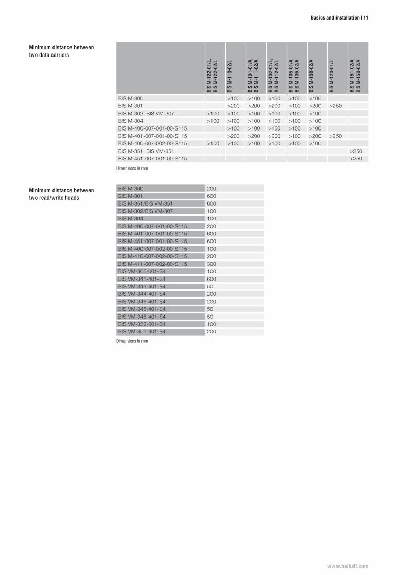
BIS M-300 >100 >100 >150 >100 >100BIS M-301 >200 >200 >200 >100 >200 >250BIS M-302, BIS VM-307 >100 >100 >100 >100 >100 >100BIS M-304 >100 >100 >100 >100 >100 >100BIS M-400-007-001-00-S115 >100 >100 >150 >100 >100BIS M-401-007-001-00-S115 >200 >200 >200 >100 >200 >250BIS M-400-007-002-00-S115 >100 >100 >100 >100 >100 >100BIS M-351, BIS VM-351 >250BIS M-451-007-001-00-S115 >250
BIS M-300 200BIS M-301 600BIS M-351/BIS VM-351 600BIS M-302/BIS VM-307 100BIS M-304 100BIS M-400-007-001-00-S115 200BIS M-401-007-001-00-S115 600BIS M-451-007-001-00-S115 600BIS M-400-007-002-00-S115 100BIS M-410-007-002-00-S115 200BIS M-411-007-002-00-S115 300BIS VM-305-001-S4 100BIS VM-341-401-S4 600BIS VM-343-401-S4 50BIS VM-344-401-S4 200BIS VM-345-401-S4 200BIS VM-346-401-S4 50BIS VM-348-401-S4 50BIS VM-352-001-S4 100BIS VM-355-401-S4 200
Minimum distance between two data carriers
Minimum distance between two read/write heads
Dimensions in mm
Dimensions in mm
12 | RFID
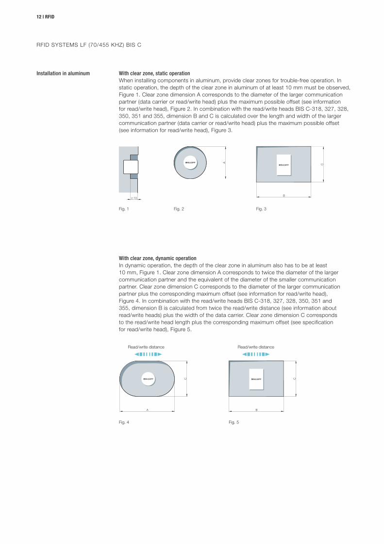
Fig. 1 Fig. 2 Fig. 3
Fig. 4 Fig. 5
Read/write distance Read/write distance
Installation in aluminum With clear zone, static operationWhen installing components in aluminum, provide clear zones for trouble-free operation. In static operation, the depth of the clear zone in aluminum of at least 10 mm must be observed, Figure 1. Clear zone dimension A corresponds to the diameter of the larger communication partner (data carrier or read/write head) plus the maximum possible offset (see information for read/write head), Figure 2. In combination with the read/write heads BIS C-318, 327, 328, 350, 351 and 355, dimension B and C is calculated over the length and width of the larger communication partner (data carrier or read/write head) plus the maximum possible offset (see information for read/write head), Figure 3.
With clear zone, dynamic operationIn dynamic operation, the depth of the clear zone in aluminum also has to be at least 10 mm, Figure 1. Clear zone dimension A corresponds to twice the diameter of the larger communication partner and the equivalent of the diameter of the smaller communication partner. Clear zone dimension C corresponds to the diameter of the larger communication partner plus the corresponding maximum offset (see information for read/write head), Figure 4. In combination with the read/write heads BIS C-318, 327, 328, 350, 351 and 355, dimension B is calculated from twice the read/write distance (see information about read/write heads) plus the width of the data carrier. Clear zone dimension C corresponds to the read/write head length plus the corresponding maximum offset (see specification for read/write head), Figure 5.
RFID SYSTEMS LF (70/455 KHZ) BIS C
www.balluff.com
Basics and installation | 13
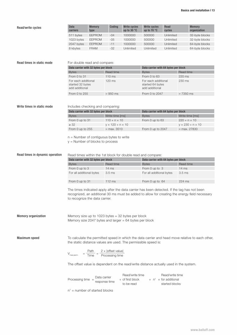
For double read and compare:Data carrier with 32 bytes per block Data carrier with 64 bytes per block
Bytes Read time Bytes Read timeFrom 0 to 31 110 ms From 0 to 63 220 msFor each additional started 32 bytes add additional
120 ms For each additional started 64 bytes add additional
230 ms
From 0 to 255 = 950 ms From 0 to 2047 = 7350 ms
Read times within the 1st block for double read and compare:Data carrier with 32 bytes per block Data carrier with 64 bytes per block
Bytes Read time Bytes Read timeFrom 0 up to 3 14 ms From 0 up to 3 14 msFor all additional bytes 3.5 ms For all additional bytes 3.5 ms
From 0 up to 31 112 ms From 0 up to 64 224 ms
The times indicated apply after the data carrier has been detected. If the tag has not been recognized, an additional 30 ms must be added to allow for creating the energy field necessary to recognize the data carrier.
Includes checking and comparing:Data carrier with 32 bytes per block Data carrier with 64 bytes per block
Bytes Write time [ms] Bytes Write time [ms]From 0 up to 31 110 + n × 10 From 0 up to 63 220 + n × 10≥ 32 y × 120 + n × 10 y × 230 + n × 10From 0 up to 255 = max. 3510 From 0 up to 2047 = max. 27830
n = Number of contiguous bytes to writey = Number of blocks to process
Data carriers
Memory type
Coding Write cycles up to 30 °C
Write cycles up to 70 °C
Read cycles
Memory organization
511 bytes EEPROM -04 1000000 500000 Unlimited 32-byte blocks1023 bytes EEPROM -05 1000000 500000 Unlimited 32-byte blocks2047 bytes EEPROM -11 1000000 500000 Unlimited 64-byte blocks8 kbytes FRAM -32 Unlimited Unlimited Unlimited 64-byte blocks
Read/write cycles
Read times in static mode
Read times in dynamic operation
Write times in static mode
Memory organization Memory size up to 1023 bytes = 32 bytes per blockMemory size 2047 bytes and larger = 64 bytes per block
Maximum speed To calculate the permitted speed in which the data carrier and head move relative to each other, the static distance values are used. The permissible speed is:
Vmax.perm. =Path
=2 × |offset value|
Time Processing time
The offset value is dependent on the read/write distance actually used in the system.
Processing time =Data carrier response time
+Read/write timeof first blockto be read
+ n1 ×Read/write timefor additionalstarted blocks
n1 = number of started blocks
14 | RFID
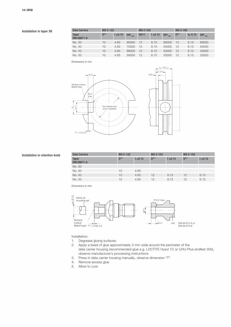
"T" = 0 to 0.2
Tool holding bore(only if required)
Sensing surface(Balluff logo)
R0.2max.
stamp asmounting aid
"T" = 0 bis 0.2
R 0.2 max.
std: DIN 69 872-A or DIN 69 872-B
Sensing surface(Balluff logo)
Installation:1. Degrease gluing surfaces.2. Apply a bead of glue approximately 3 mm wide around the perimeter of the
data carrier housing (recommended glue e.g. LOCTITE Hysol 1C or UHU-Plus endfest 300), observe manufacturer’s processing instructions
3. Press in data carrier housing manually, observe dimension “T”4. Remove excess glue5. Allow to cure
Data Carriers BIS C-122 BIS C-103 BIS C-105
Taper DIN 69871-A
DH11 t ±0.15 rpm max DH11 t ±0.15 rpm max DH11 t± 0.15 rpm max
No. 30 10 4.65 90000 12 8.15 68000 12 6.15 68000No. 40 10 4.65 75000 12 8.15 54000 12 6.15 54000No. 45 10 4.65 66000 12 8.15 43000 12 6.15 43000No. 50 10 4.65 59000 12 8.15 33000 12 6.15 33000
Dimensions in mm
Data Carriers BIS C-122 BIS C-103 BIS C-105
Taper DIN 69871-A
DH11 t ±0.15 DH11 t ±0.15 DH11 t ±0.15
No. 30No. 40 10 4.65No. 45 10 4.65 12 8.15 12 6.15No. 50 10 4.65 12 8.15 12 6.15
Dimensions in mm
Installation in taper SK
Installation in retention knob
www.balluff.com
Basics and installation | 15
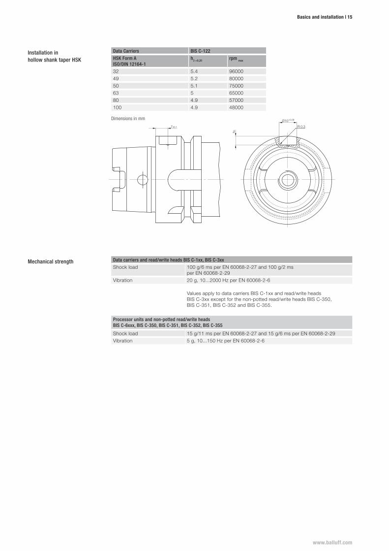
Data Carriers BIS C-122 BIS C-103 BIS C-105
Taper DIN 69871-A
DH11 t ±0.15 DH11 t ±0.15 DH11 t ±0.15
No. 30No. 40 10 4.65No. 45 10 4.65 12 8.15 12 6.15No. 50 10 4.65 12 8.15 12 6.15
Dimensions in mm
Data Carriers BIS C-122
HSK Form A ISO/DIN 12164-1
h3 +0,20 rpm max
32 5.4 9600049 5.2 8000050 5.1 7500063 5 6500080 4.9 57000100 4.9 48000
Dimensions in mm
Data carriers and read/write heads BIS C-1xx, BIS C-3xx
Shock load 100 g/6 ms per EN 60068-2-27 and 100 g/2 ms per EN 60068-2-29
Vibration 20 g, 10...2000 Hz per EN 60068-2-6
Values apply to data carriers BIS C-1xx and read/write heads BIS C-3xx except for the non-potted read/write heads BIS C-350, BIS C-351, BIS C-352 and BIS C-355.
Processor units and non-potted read/write headsBIS C-6xxx, BIS C-350, BIS C-351, BIS C-352, BIS C-355
Shock load 15 g/11 ms per EN 60068-2-27 and 15 g/6 ms per EN 60068-2-29Vibration 5 g, 10...150 Hz per EN 60068-2-6
Mechanical strength
Installation in hollow shank taper HSK
16 | RFID
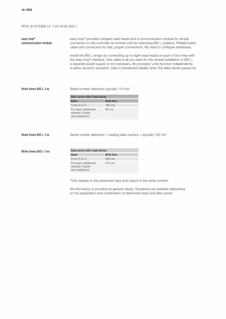
easy loop® provides compact read heads and a communication module for simple connection to the controller at minimal cost for extending BIS L systems. Prefabricated cable and connectors for fast, proper connections. No need to configure addresses.
Install the BIS L simply by connecting up to eight read heads on each of two lines with the easy loop® interface. One cable is all you need for the simple installation of BIS L, a separate power supply is not necessary. All processor units function independently to allow dynamic operation: Data is transferred reliably when the data carrier passes by.
easy loop® communication module
Serial number detection typically 110 ms*
Serial number detection = reading data carriers = typically 100 ms*
Read times BIS L-1xx
Write times BIS L-1xx
Read times BIS L-1xx
Data carrier with 4 byte blocks
Bytes Read time
From 0 to 3 180 msFor each additional started 4 bytes add additional
90 ms
Data carrier with 4 byte blocks
Bytes Write time
From 0 to 3 305 msFor each additional started 4 bytes add additional
215 ms
*Only applies to the parameter type and output of the serial number.
All information is provided as general values. Deviations are possible depending on the application and combination of read/write head and data carrier.
RFID SYSTEMS LF (125 KHZ) BIS L
www.balluff.com
Basics and installation | 17
BIS
L-10
0-01
/L
BIS
L-10
1-01
/L
BIS
L-10
2-01
/L
BIS
L-10
3-05
/L
BIS
L-20
0-03
/L
BIS
L-10
0-05
/L-R
O
BIS
L-20
1-03
/L
BIS
L-10
1-05
/L-R
O
BIS
L-20
2-03
/L
BIS
L-10
2-05
/L-R
O
BIS
L-20
3-03
/L
BIS
L-10
3-05
/L-R
O
BIS
L-15
0-05
/A
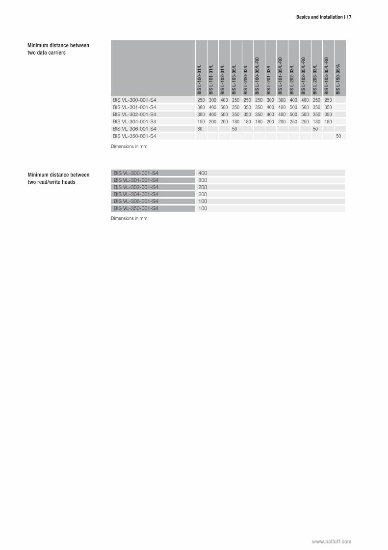
BIS VL-300-001-S4 250 300 400 250 250 250 300 300 400 400 250 250
BIS VL-301-001-S4 300 400 500 350 350 350 400 400 500 500 350 350
BIS VL-302-001-S4 300 400 500 350 350 350 400 400 500 500 350 350
BIS VL-304-001-S4 150 200 200 180 180 180 200 200 250 250 180 180
BIS VL-306-001-S4 80 50 50
BIS VL-350-001-S4 50
BIS VL-300-001-S4 400BIS VL-301-001-S4 800BIS VL-302-001-S4 200BIS VL-304-001-S4 200BIS VL-306-001-S4 100BIS VL-350-001-S4 100
Minimum distance between two data carriers
Minimum distance between two read/write heads
Dimensions in mm
Dimensions in mm

CONTACT OUR WORLDWIDE
SUBSIDIARIES
Doc
. no.
950
373
· EN
· A
21 ·
Sub
ject
to c
hang
es.
HeadquartersBalluff GmbHSchurwaldstrasse 973765 Neuhausen a. d. F.GermanyPhone +49 7158 [email protected]
www.balluff.com