Embed Size (px)
Citation preview
THI NAHI HA UNA MARTINA DA UN MINI US009878498B2
( 12 ) United States Patent Chu et al .
( 10 ) Patent No . : US 9 , 878 , 498 B2 ( 45 ) Date of Patent : Jan . 30 , 2018
( 56 ) References Cited ( 54 ) METHOD AND APPARATUS FOR REMOVING SUPPORT MATERIAL U . S . PATENT DOCUMENTS
@ ( 71 ) Applicant : Phoenix Analysis and Design Technologies , Inc . , Tempe , AZ ( US ) 769 , 496 A *
2 , 205 , 053 A *
9 / 1904 Seipelt . . . . . . . . . . . . . . A47J 36 / 20 99 / 412
6 / 1940 Thackeray . . . . . . . . . . . . . . GO3D 3 / 02 134 / 183
( Continued ) @ ( 72 ) Inventors : Kou - Rey Chu , Chandler , AZ ( US ) ;
Solomon Pena , Tempe , AZ ( US ) ; Mark C . Johnson
FOREIGN PATENT DOCUMENTS @ ( 73 ) Assignee : Phoenix Analysis and Design
Technologies , Inc . , Tempe , AZ ( US ) DE JP
102009061069 A1 * 6 / 2011 . . . . . . . CIID 3 / 2068 08294681 A * 11 / 1996
@ ( * ) Notice : Subject to any disclaimer , the term of this patent is extended or adjusted under 35 U . S . C . 154 ( b ) by 3 days .
OTHER PUBLICATIONS Abstract : JP08294681A ; Imashiro et al . , 1996 . *
( Continued ) ( 21 ) Appl . No . : 14 / 922 , 175 ( 22 ) Filed : Oct . 25 , 2015 Primary Examiner — Mikhail Kornakov
Assistant Examiner — Natasha N Campbell ( 74 ) Attorney , Agent , or Firm — James L Farmer ( 65 ) Prior Publication Data
US 2016 / 0325507 A1 Nov . 10 , 2016 ( 57 )
Related U . S . Application Data ( 60 ) Provisional application No . 62 / 179 , 267 , filed on May
4 , 2015 .
( 51 ) Int . CI . B08B 3 / 04 ( 2006 . 01 ) B29C 67 / 00 ( 2017 . 01 )
( Continued ) ( 52 ) U . S . CI .
CPC . . . . . . . . . . B29C 67 / 0096 ( 2013 . 01 ) ; B08B 3 / 045 ( 2013 . 01 ) ; B08B 3 / 047 ( 2013 . 01 ) ; B29C 64 / 35
( 2017 . 08 ) ; B33Y 40 / 00 ( 2014 . 12 ) ( 58 ) Field of Classification Search
CPC . . . . . . . . . B08B 3 / 045 ; B08B 3 / 047 ; B08B 3 / 006 ; B29C 67 / 0096 ; B29C 71 / 0009 ; B33Y
40 / 00 See application file for complete search history .
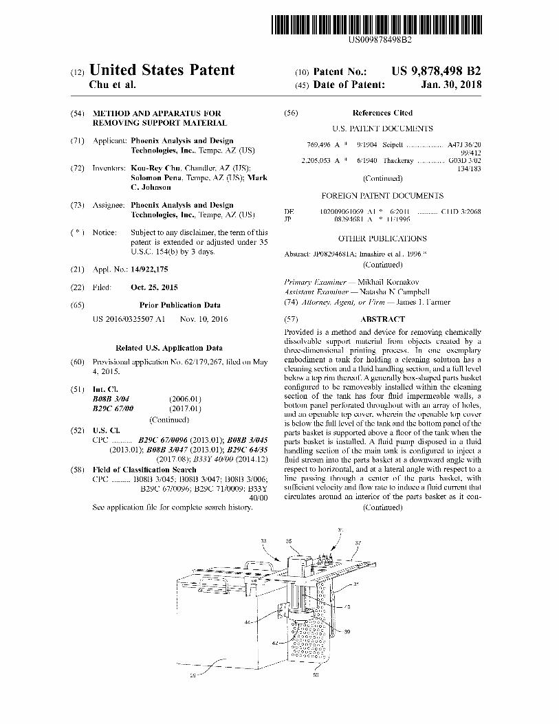
ABSTRACT Provided is a method and device for removing chemically dissolvable support material from objects created by a three - dimensional printing process . In one exemplary embodiment a tank for holding a cleaning solution has a cleaning section and a fluid handling section , and a full level below a top rim thereof . A generally box - shaped parts basket configured to be removeably installed within the cleaning section of the tank has four fluid impermeable walls , a bottom panel perforated throughout with an array of holes , and an openable top cover , wherein the openable top cover is below the full level of the tank and the bottom panel of the parts basket is supported above a floor of the tank when the parts basket is installed . A fluid pump disposed in a fluid handling section of the main tank is configured to inject a fluid stream into the parts basket at a downward angle with respect to horizontal , and at a lateral angle with respect to a line passing through a center of the parts basket , with sufficient velocity and flow rate to induce a fluid current that circulates around an interior of the parts basket as it con
( Continued )
mm 33 33 35 35
31
OOP 40 b0 Ooo DOO
44 -
020 JOOOO OOO OOO000 W ODOO0000 OOO00000 DOOOOOOO OOOOOOOOO 00000000 OOOOOOOOO 00000000 000000000
42
29 50
US 9 , 878 , 498 B2 Page 2
tinuously descends and exits the parts basket through the perforated bottom panel .
19 Claims , 12 Drawing Sheets
( 51 ) Int . CI . B29C 64 / 35 B33Y 40 / 00
( 2017 . 01 ) ( 2015 . 01 )
( 56 ) References Cited
U . S . PATENT DOCUMENTS 4 , 870 , 982 A * 10 / 1989 Liu . . . . . . . . . . B08B 3 / 12
134 / 1 7 , 546 , 841 B2 8 , 459 , 280 B2
2005 / 0103360 A1 *
6 / 2009 Tafoya 6 / 2013 Swanson et al . 5 / 2005 Tafoya . . . . . . . .
2008 / 0210276 A1 * 9 / 2008 Porter B08B 3 / 045
134 / 18 B08B 3 / 006
134 / 198 2011 / 0186081 AL 8 / 2011 Dunn et al .
OTHER PUBLICATIONS Information brochre published by Dimension 3D Printers , Stratasys , Inc . , 7665 Commerce Way , Eden Prairie , MN 55344 - 2020 U . S . A . , available online : http : / / www . capinc . com / wp - content / uploads / 2013 / 09 / Dimension - SS - SCA - 01 - 13 - web . pdf , Copyright 2010 .
* cited by examiner
U . S . Patent Jan . 30 , 2018 Sheet 1 of 12 US 9 , 878 , 498 B2
FIG . 1 Prior Art
25
- 21
- 12 34
FIG . 2
U . S . Patent Jan . 30 , 2018 Sheet 2 of 12 US 9 , 878 , 498 B2
29
31
/ 000000 ove
W
WW .
w
4
FIG . 3
U . S . Patent Jan . 30 , 2018 Sheet 3 of 12 US 9 , 878 , 498 B2
FIG . 4
Wwwwwwwwwwwwwww 27
Lee ' s
33 35
Oo bo
Pooo boo
44 - 7 39
Ovo OOOOO OOO OOOOOO Opoooooo OOOOOOOOO OOOOOOOO OOOOOOOOO OOOOOOOO 000000000 OOOOOOOO 000000000
42
FIG . 5
U . S . Patent Jan . 30 , 2018 Sheet 4 of 12 US 9 , 878 , 498 B2
27
uur * * *
00 000
49 0000000000 000000000000 0000000000000 000000000000 0000000000 00000000
FIG . 6
U . S . Patent Jan . 30 , 2018 Sheet 5 of 12 US 9 , 878 , 498 B2
59
59 LE - 57
54
FIG . 7 5
29
Bu 60
53 54
FIG . 8 o
U . S . Patent
52
Jan . 30 , 2018
100 1000 5000 ) 2000 6000
FIG . 9
00000 000000 00000000 000000000 10000 0000000000000000000 000000 0000000000000000000000 0000000000000000000000000 00000000000000000000000000004 0000000000000000000000000000 0000000000000000000000000000 0000000000000000000000000000 0000000000000000000000000000 00000000000000000000000000001 0000000000000000000000000000 0000000000000000000000000000 000000000000000000000000000 100000000000000000000000000001 X 0000000000000000000000000000 DOQQ00000000000000000000000000 ADD000000000000000000000000000 000000000000000000000000000000 0000000000000000000000000000000000 a 2000 000000000000000000000000000000000000000 / IA 0000000000000000000000000000000000000000 100000000000000000000000000000000000000000 10000000000000000000000000000000000000000 / 00000000000000000000000000000000000000000 00000000000000000000000000000000000000000 / 10000000000000000000000000000000000000000 / 0000000000000000000000000000000000000 V00000000000000000000000000000000000 VOO00000000000000000000000000000000 00000000000000000000000000000000 10000000000000000000000000000000 D000000000000000000000000000000 000000000000000000000000000000 10000000000000000000000000000000 10000000000000000000000000000000 0000000000000000000000000000000 p000000000000000000000000000000 0000000000000000000000000000000 POO0000000000000000000000000000 0000000000000000000000000000000 WOR0000000000000000000000000000 / V00000000000000000000000000 v0000000000000000000000 000 buvo 00000000
900000000001 0000000 /
V00000000 200000
20000000
10000
V00000
Sheet 6 of 12
-
56
les
0001
63
. OOS
6000 0000 / 6000 5000 10000 / 6000 0000 /
US 9 , 878 , 498 B2
U . S . Patent Jan . 30 , 2018 Sheet 7 of 12 US 9 , 878 , 498 B2
56
27
FIG . 10
29
712
FIG . 11
US 9 , 878 , 498 B2 U . S . Patent Jan . 30 , 2018 Sheet 8 of 12
67
S IIII - 3
ora
FIG . 12
U . S . Patent Jan . 30 , 2018 Sheet 9 of 12 US 9 , 878 , 498 B2
29
Ñ
FIG . 13
U . S . Patent Jan . 30 , 2018 Sheet 10 of 12 US 9 , 878 , 498 B2
O 0 . 0 . 0 . 0 . 2 . 2 . 0 . . . . . . . . . . . .
OOOOOOOOO OOOOOOOOO OOOOOOOO OOOOOOOOOOOO OOOO
OOOOOOOOOOOOOOOOOOOOOOOOOOOOOO OOOOOOOOOOOOOOOOOOOOOOOOOOOO OOOOOOOOOOOOOOO OOOOOOOOOOOOOOOOOOOOOOOOOOOOO OOOOOOOOOOOOOOOOOOOOOO OOOOOOOOOOOOOOOOOOOOO OOOOOOOOOOOOOOOO OOOOOOOOO OOOOOOOOOOOOOOOOOOOOOOO OOOOOOOOOOOOOOOOOOOOOO OOOOOOO OOOOOOOOOOOOOOOOOOOOOOO OOOOOO OOOOOO OOOOOO OOOOOO OOOOOOOOOOOOOOO OOOOOOOOOOOOO OOOOOOOOOOOOOOO OOOOOOOOOOOOOO OOOOOOOOOOOO OOOOOOOOOOOOOO
Ooo .
OOOOOOOOOOOOOOO OOOOOOO OOOOOOOOOOO / OOOOOOOOOOO / OOOOOOOOOOO OOOOOOOOO
OOOOOOOOOOOOOOOOOOO wwwwwwwwwwwwwwww OOOOOOOOOO
OROOOOOOOOOOOOOOOOOOO . OOOOOOOOOO OOOOOOOOOOOOOOOOOOOOOO OOOOOOOOOO OOOOOOOOOOO0000000 OOOOOOOO OOOOOOOOOOOOO OOOOOOOOOOO
OOOOOOOOO OOOOOOOOOO OOOO OOOOOO
O0OUOO OOOOOOOOOOOO OOOOOOOOOOOOOO OOOOOOO / OOOOO !
47 52 FIG . 14
AMPADE
5 : 7 .
42 3 W I WITEIMLITEXTWITTEETTI MOTOMMwemwwwww
64 FIG . 15
wowow . - - - U . S . Patent Jan . 30 , 2018 Sheet 11 of 12 US 9 , 878 , 498 B2
B -
We 45
Nozzle Exit Aspect Ratio = A / B
FIG . 16
U . S . Patent Jan . 30 , 2018 Sheet 12 of 12 US 9 , 878 , 498 B2
| B , ,
FIG . 18
44
44
FIG . 17
US 9 , 878 , 498 B2
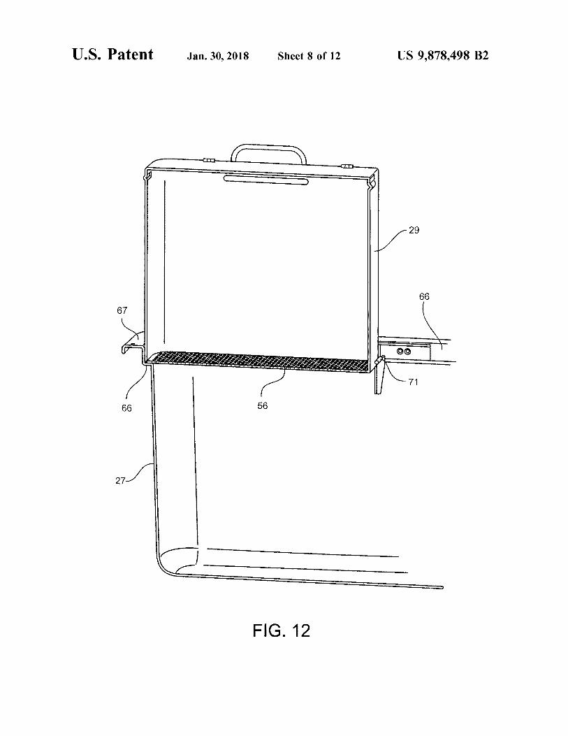
METHOD AND APPARATUS FOR FIG . 11 is a top perspective of the tank and parts basket , REMOVING SUPPORT MATERIAL with the parts basket supported atop the tank in the draining
position ; Provisional Patent Application Ser . No . 62 / 179 , 267 to FIG . 12 is a cut - away side view of the parts basket and
which the present application claims priority , is hereby 5 tank of FIG . 11 , showing the lower shelf of the tank rim incorporated by reference . supporting the front of the basket , and the notched flange
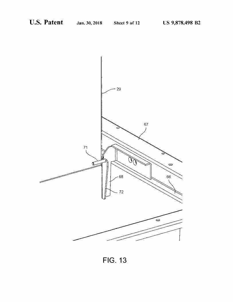
that supports the back of the parts basket ; TECHNICAL FIELD AND BACKGROUND FIG . 13 is a close up perspective view of a notched flange
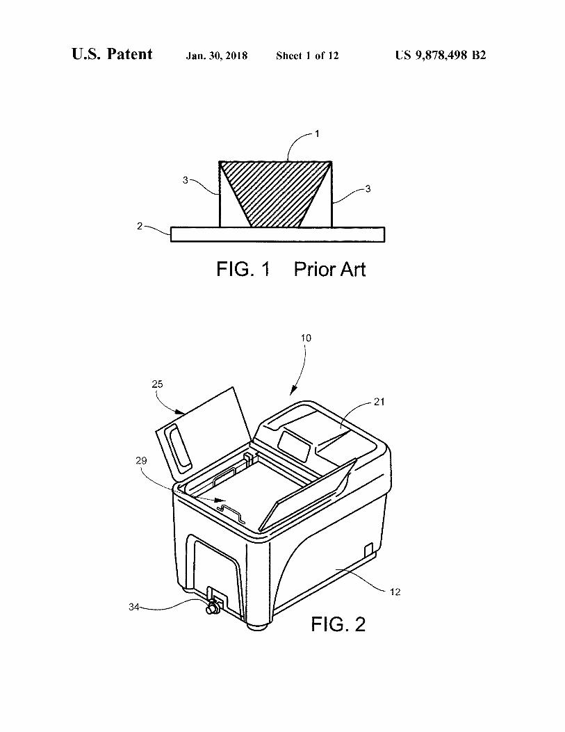
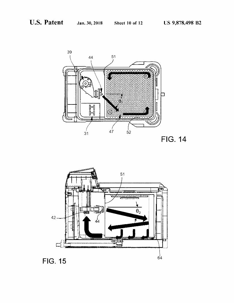
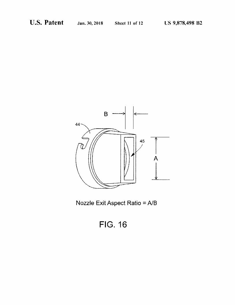
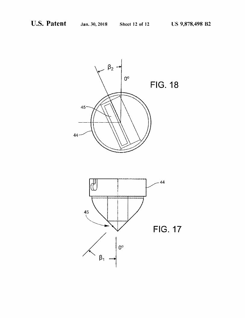
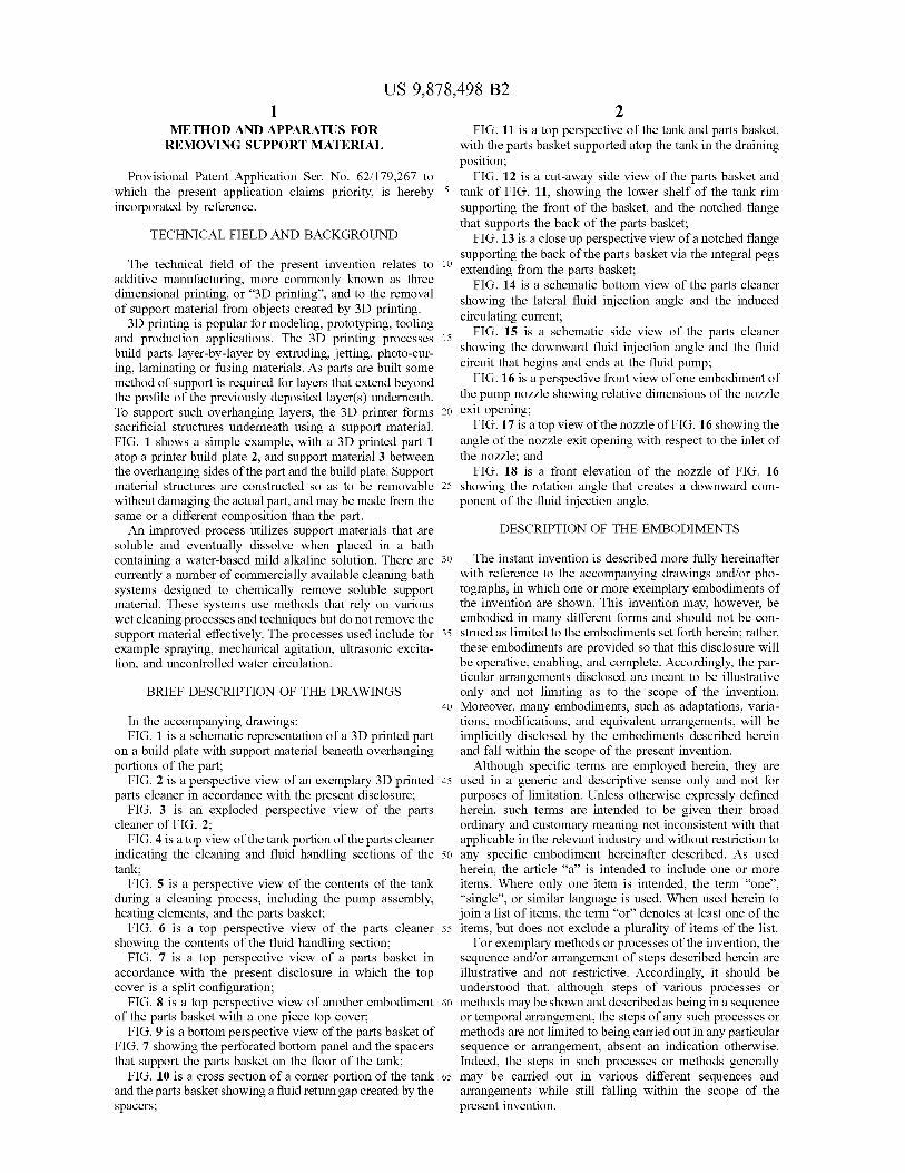
supporting the back of the parts basket via the integral pegs The technical field of the present invention relates to 10 º extending from the parts basket ; additive manufacturing , more commonly known as three FIG . 14 is a schematic bottom view of the parts cleaner dimensional printing , or “ 3D printing ” , and to the removal showing the lateral fluid injection angle and the induced of support material from objects created by 3D printing . circulating current ; 3D printing is popular for modeling , prototyping , tooling FIG . 15 is a schematic side view of the parts cleaner and production applications . The 3D printing processes 15 build parts layer - by - layer by extruding , jetting , photo - cur showing the downward fluid injection angle and the fluid ing , laminating or fusing materials . As parts are built some circuit that begins and ends at the fluid pump ; method of support is required for layers that extend beyond FIG . 16 is a perspective front view of one embodiment of the profile of the previously deposited layer ( s ) underneath . the pump nozzle showing relative dimensions of the nozzle To support such overhanging layers , the 3D printer forms 20 exit opening ; sacrificial structures underneath using a support material . FIG . 17 is a top view of the nozzle of FIG . 16 showing the FIG . 1 shows a simple example , with a 3D printed part 1 angle of the nozzle exit opening with respect to the inlet of atop a printer build plate 2 , and support material 3 between the nozzle ; and the overhanging sides of the part and the build plate . Support FIG . 18 is a front elevation of the nozzle of FIG . 16 material structures are constructed so as to be removable 25 showing the rotation angle that creates a downward com without damaging the actual part , and may be made from the ponent of the fluid injection angle . same or a different composition than the part . An improved process utilizes support materials that are DESCRIPTION OF THE EMBODIMENTS
soluble and eventually dissolve when placed in a bath containing a water - based mild alkaline solution . There are 30 The instant invention is described more fully hereinafter currently a number of commercially available cleaning bath with reference to the accompanying drawings and / or pho systems designed to chemically remove soluble support tographs , in which one or more exemplary embodiments of material . These systems use methods that rely on various the invention are shown . This invention may , however , be wet cleaning processes and techniques but do not remove the embodied in many different forms and should not be con support material effectively . The processes used include for 35 strued as limited to the embodiments set forth herein ; rather , example spraying , mechanical agitation , ultrasonic excita these embodiments are provided so that this disclosure will tion , and uncontrolled water circulation . be operative , enabling , and complete . Accordingly , the par
ticular arrangements disclosed are meant to be illustrative BRIEF DESCRIPTION OF THE DRAWINGS only and not limiting as to the scope of the invention .
40 Moreover , many embodiments , such as adaptations , varia In the accompanying drawings : tions , modifications , and equivalent arrangements , will be FIG . 1 is a schematic representation of a 3D printed part implicitly disclosed by the embodiments described herein
on a build plate with support material beneath overhanging and fall within the scope of the present invention . portions of the part ; Although specific terms are employed herein , they are
FIG . 2 is a perspective view of an exemplary 3D printed 45 used in a generic and descriptive sense only and not for parts cleaner in accordance with the present disclosure ; purposes of limitation . Unless otherwise expressly defined
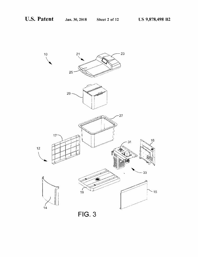
FIG . 3 is an exploded perspective view of the parts herein , such terms are intended to be given their broad cleaner of FIG . 2 ; ordinary and customary meaning not inconsistent with that
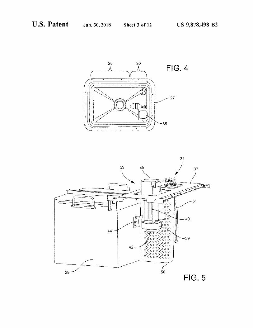
FIG . 4 is a top view of the tank portion of the parts cleaner applicable in the relevant industry and without restriction to indicating the cleaning and fluid handling sections of the 50 any specific embodiment hereinafter described . As used tank ; herein , the article “ a ” is intended to include one or more
FIG . 5 is a perspective view of the contents of the tank items . Where only one item is intended , the term " one ” , during a cleaning process , including the pump assembly , " single ” , or similar language is used . When used herein to heating elements , and the parts basket ; join a list of items , the term “ or ” denotes at least one of the
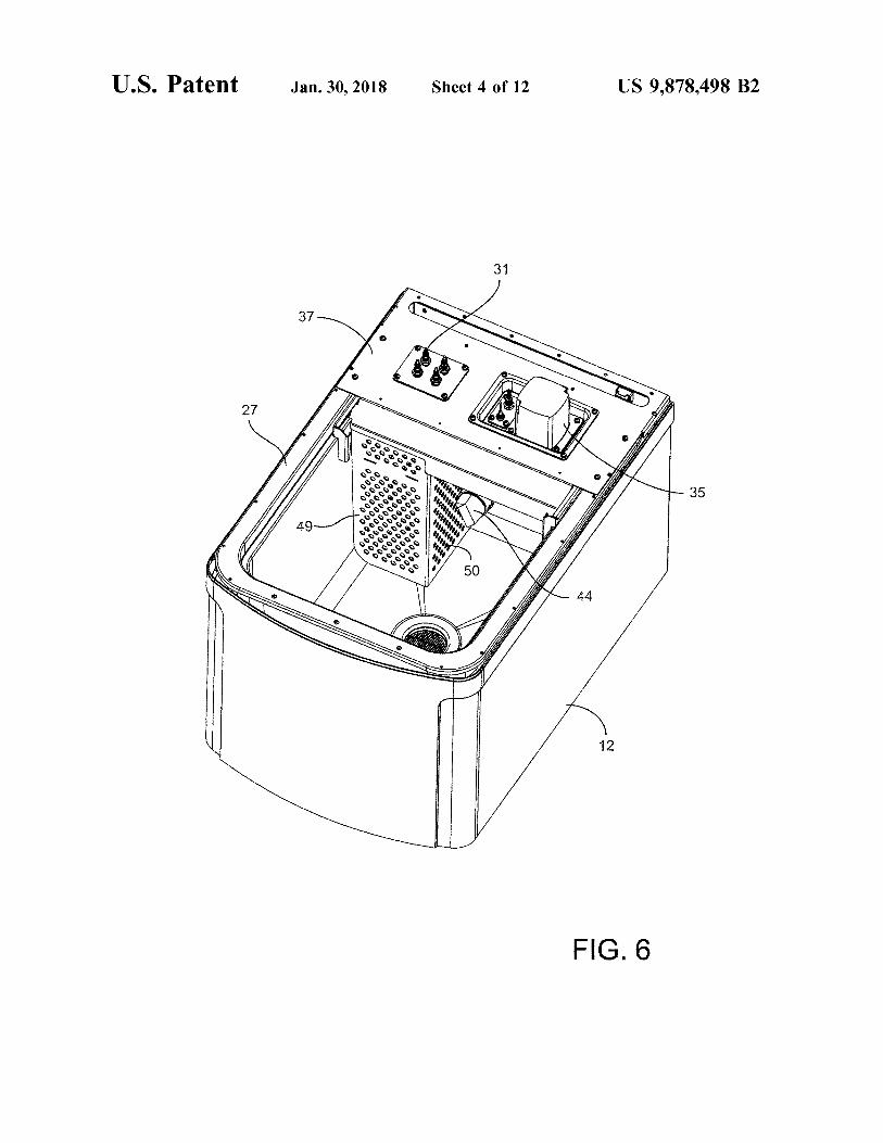
FIG . 6 is a top perspective view of the parts cleaner 55 items , but does not exclude a plurality of items of the list . showing the contents of the fluid handling section ; For exemplary methods or processes of the invention , the
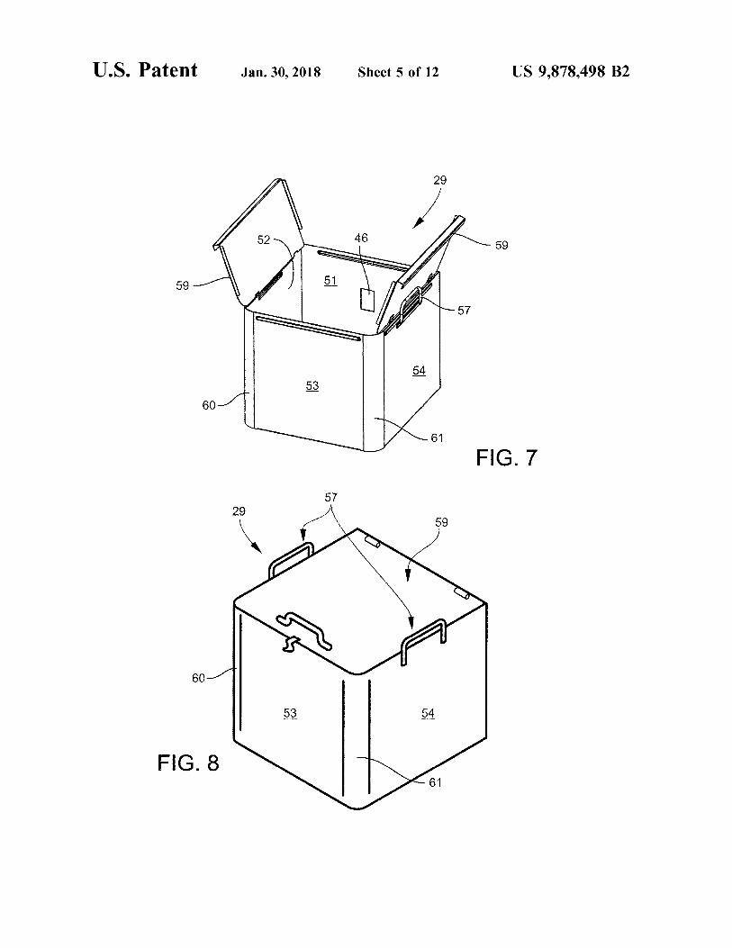
FIG . 7 is a top perspective view of a parts basket in sequence and / or arrangement of steps described herein are accordance with the present disclosure in which the top illustrative and not restrictive . Accordingly , it should be cover is a split configuration ; understood that , although steps of various processes or
FIG . 8 is a top perspective view of another embodiment 60 methods may be shown and described as being in a sequence of the parts basket with a one piece top cover ; or temporal arrangement , the steps of any such processes or
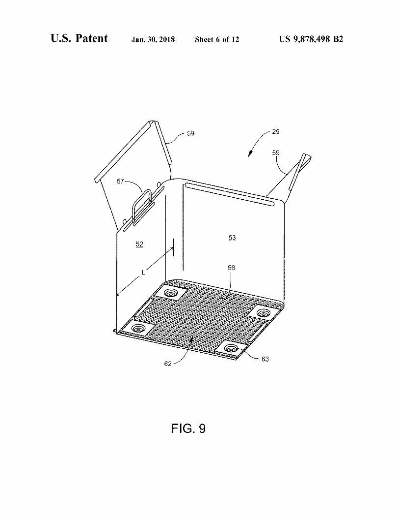
FIG . 9 is a bottom perspective view of the parts basket of methods are not limited to being carried out in any particular FIG . 7 showing the perforated bottom panel and the spacers sequence or arrangement , absent an indication otherwise . that support the parts basket on the floor of the tank ; Indeed , the steps in such processes or methods generally
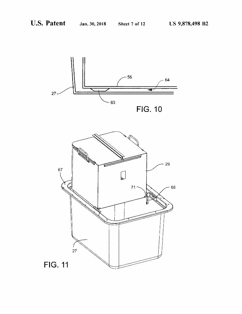
FIG . 10 is a cross section of a corner portion of the tank 65 may be carried out in various different sequences and and the parts basket showing a fluid return gap created by the arrangements while still falling within the scope of the spacers ; present invention .
US 9 , 878 , 498 B2
Additionally , any references to advantages , benefits , top 21 create a sealed compartment that isolates the motor 35 unexpected results , or operability of the present invention from corrosive vapors produced by the heated cleaning fluid . are not intended as an affirmation that the invention has been The pump 39 draws in fluid from underneath through an previously reduced to practice or that any testing has been intake 42 , and discharges fluid at a predetermined velocity , performed . Likewise , unless stated otherwise , use of verbs 5 flow rate , and direction through an injection nozzle 44 aimed in the past tense ( present perfect or preterit ) is not intended at an opening 46 in a side of the parts basket . The heating to indicate or imply that the invention has been previously elements 31 are also attached to the baffle plate 37 , and reduced to practice or that any testing has been performed . extend downward into the tank . The heating elements are
Referring now initially to FIGS . 2 through 4 , an auto - normally submerged in cleaning fluid when the tank is full , mated cleaner for removing dissolvable support material is 10 and may be partitioned in one side of the fluid handling indicated at reference numeral 10 . The cleaner 10 comprises section 30 behind porous dividers 49 and 50 as best seen in an outer cabinet 12 with front and back panels 14 , 16 , right FIG . 6 . and left side panels 15 , 17 , a bottom 19 , and a top 21 that Referring now to FIGS . 7 through 9 , the parts basket 29 includes a display and control housing 23 and a lid 25 . The is a box made of a corrosion resistant material such as lid 25 may have left and right halves hinged along their outer 15 stainless steel , with back and front walls 51 , 53 , left and right edges to top edges of the cabinet side panels 15 , 17 , and side walls 52 , 54 , a bottom panel 56 , handles 57 , and a configured to open outward to the left and right as shown . hinged top cover 59 . The top cover 59 may be a split The lid 25 opens to a large watertight tank 27 that substan - configuration like that shown in FIG . 7 , or a one - piece tially conforms to the available space inside of the outer design like that shown in FIG . 8 . Because of its simplicity cabinet 12 . The inside of the tank 27 is divided into a 20 the one piece design may be preferable for relatively small cleaning section 28 containing a removable parts basket 29 , parts baskets that may be easily opened with one hand . and a fluid handling section 30 that includes heating ele - However for larger baskets that result in a difficult reach for ments 31 and a pump assembly 33 . a user to open the cover and monitor parts being cleaned , the
In operation the tank 27 is filled substantially to the top split configuration may be preferable because the user ' s with a heated , water based cleaning solution specifically 25 arms are conveniently directed away from heated vapor formulated to chemically remove the dissolvable type sup - generated by the cleaning solution . port material . The size of the tank is substantially maximized The bottom panel 56 of the parts basket is perforated for a given cabinet configuration to maximize the time throughout with an array of substantially evenly distributed before the cleaning solution becomes ineffective due to holes 62 ( see FIG . 9 ) , whereas except for the opening 46 , the saturation with the dissolved support materials . In one 30 walls 51 - 54 and the hinged cover 59 are solid ( or not embodiment the tank has a 27 gallon capacity . Once the perforated ) . Thus , when the cover is closed , the only sub cleaning solution has become saturated , the tank may be stantial exit for fluid injected into the parts basket through drained and cleaned to remove and replace the cleaning opening 46 ( ignoring any back flow through opening 46 ) is solution using a tank drain valve 34 located at the front or through the holes 62 in the bottom panel 56 . The quantity , back of the cabinet . The valve may include a barbed outlet 35 size , and spacing of the holes 62 is selected to encourage and that permits the secure attachment of a hose for draining facilitate a dynamic circulating fluid flow through the parts
User control of cleaning times and temperatures is per - basket . In one embodiment the holes 62 account for between formed using push button controls and digital displays of the 15 and 60 percent of the total surface area of bottom panel display and control housing 23 . A built - in microprocessor 56 ; and in a more particular embodiment the holes 62 controller regulates and controls cleaning times and cleaning 40 account for approximately 20 percent of the total surface solution temperatures , as well as performing safety func - area of panel 56 . tions to alert the user of problems , and if necessary halt a The inventors have further discovered that the desired cleaning operation until the problems are resolved . dynamic circulation of the fluid in the parts basket can be
Two means , or levels are provided for protecting against enhanced by rounding the corners , and in particular the front an over temperature condition of the cleaning solution . In 45 corners 60 , 61 at the intersections of the front wall 53 and the first level , the microprocessor system attempts to shut off side walls 52 , 54 . By rounding at least the two front corners , power to the heater and alerts the user with visual and a fluid current that enters the parts basket through the back audible annunciators . A second level of protection is pro - wall 51 is redirected at least twice in an efficient manner , vided by a thermal cutout ( TCO ) mounted to the tank . The substantially completing at least one loop around the inside TCO operates independently of the microprocessor , and if 50 of the basket , and thereby encountering all of the parts in the the first level of protection fails , or goes unnoticed , the TCO parts basket at least once before exiting out the bottom panel will trip and remove power to the heater to prevent damage 56 . The amount of corner curvature is selected to efficiently to the cleaner or risk of a fire . turn the fluid current without resulting in significant turbu
To prevent spills or splashing of the cleaning solution , or lence , and is related to the geometry of the parts basket , and damage to the pump and heaters , the level of the cleaning 55 the velocity or momentum of the fluid stream entering the solution in the tank is monitored by the microprocessor parts basket . In relation to the dimensions of the parts basket , electronics . In one embodiment a float sensor detects high or the corner curvature may be described as a ratio of the radius low solution levels , which then signals the microprocessor of curvature of the corner to the length of the walls , or : the level status . If high or low levels are detected , an
CR = r / L appropriate visual annunciator will flash , an audible alert 60 will beep , and the operation of the cleaner will be halted . where “ CR ” is the curvature ratio ; " r " is the radius of
Referring now also to FIGS . 5 and 6 , the pump assembly curvature of the front corners ; and “ L ” is the corner - to 33 includes a motor 35 supported by a baffle plate 37 and corner wall length of a square parts basket ( see FIG . 8 ) . For connected to an impeller type pump 39 by a drive shaft 40 . example , in one preferred embodiment a suitable curvature In operation the pump 39 is submerged in the cleaning fluid 65 ratio ( CR ) is at least 0 . 1 . In another preferred embodiment that fills the tank 27 , and the motor 35 is positioned above the curvature ratio is in a range of between about 0 . 1 and a full level of the fluid . The baffle plate 37 together with the 0 . 3 . , and in yet another more specific embodiment the ratio
US 9 , 878 , 498 B2
is about 0 . 17 . An example of the latter is a square parts and vertically at or above the middle of the wall . In another basket with L = 12 inches , and r = 2 inches . more particular embodiment , the bottom edge of the opening
With the cabinet lid 25 open , the parts basket may be is above the vertical center of the back wall 51 by an amount lowered into the tank using handles 57 until it rests on the in the range of approximately zero to two inches . bottom of the tank in a parts cleaning position , as shown for 5 The path that the fluid current takes through the parts example in FIGS . 2 and 10 . The entire parts basket is basket is represented schematically with arrows in FIGS . 14 submerged in this position when the tank is filled with and 15 . The fluid follows a circuit best seen in FIG . 15 , cleaning fluid , including the cover 59 which is also below flowing first from nozzle 44 into the parts basket , spiraling the full level of the fluid . The parts basket may be restrained downward and finally out through the bottom panel 56 , then in the cleaning position with an optional latch or lock device 10 through gap 64 between the parts basket and the tank ( not shown ) , or in the case of a metal parts basket , gravity bottom , and finally back to the pump intake 42 . The direc alone may be sufficient to prevent it from floating up off the tion of the fluid stream entering the parts basket through the bottom of tank 27 during a cleaning process . Localized opening 46 is determined by the nozzle 44 , and as can be spacers 63 may be provided under bottom panel 56 at each seen , the fluid stream is not injected straight into the parts corner to act as stand - offs , and create a fluid return gap 64 15 basket , or in other words not on a line passing through the ( see FIG . 10 ) between the parts basket bottom 56 and the middle of the parts basket . Instead the nozzle directs the bottom of the tank 27 . The fluid return gap 64 provides a fluid somewhat tangentially , at an angle in both the lateral pathway for fluid exiting the bottom of the parts basket to and vertical directions . return to the pump 39 , and is preferably large enough to Referring first to the top view of FIG . 14 , the fluid may be avoid causing a flow restriction under operating conditions . 20 injected at a lateral angle o , to a line passing through the In one embodiment the gap 64 is between about 0 . 3 and 1 . 0 center of the parts basket ( or more conveniently , " center inches , and in a more specific embodiment the gap is about line ” ) . The lateral angle directs the fluid stream initially 0 . 5 inches . toward side wall 52 , where it is redirected and forced to
The parts basket may be manually lifted out of the tank follow the walls around the inside of the parts basket as during or after a parts cleaning process using the handles 57 . 25 shown by the arrows 47 . The injected fluid stream in turn Once lifted out it is typically desirable to hold the parts induces a circular vortex flow pattern that involves substan basket directly above the tank long enough for all of the tially all of the fluid in the parts basket at any given time . cleaning fluid to drain out . To avoid requiring a user to To encourage the circulating flow down and out through physically hold the parts basket , the parts cleaner is the bottom of the parts basket , the direction of the injected equipped with built - in support features near the top of the 30 fluid stream also includes a downward component , indicated tank that are configured to temporarily support the parts at 0 , in FIG . 15 . The amount of the lateral and downward basket above the cleaning fluid as shown in FIGS . 11 angles are selected to create a descending spiraling , sub through 13 . In particular , a lower shelf 66 of an upper rim 67 stantially non - turbulent fluid current that completes at least of the tank 27 serves as a support for the front of the parts one loop around the inside of the parts basket before exiting basket , while a pair of flanges 68 attached to the sides of the 35 out the bottom panel 56 . Too much turbulence disrupts the tank support the back of the parts basket . Each flange 68 is flow and introduces the possibility of splashing in the basket , configured with a notch 69 to receive and support integral or can cause damage to delicate parts . In one embodiment pegs 71 that extend from the back of the parts basket . A the lateral angle of the injected stream , is between about tapered lead - in portion 72 guides the pegs around and over 30 and 65 degrees , and the downward angle 02 is between the flange 68 to the notch 69 as the parts basket is lifted out 40 about 10 and 20 degrees . In another more specific embodi of the tank . The support features thus provide a stable and ment , the lateral angle o , is about 45 degrees , and the secure means for holding the parts basket in an optimal downward angle e , is about 15 degrees . draining position over the tank . The ability of the injected fluid stream to create and
The inventors have discovered that removal of the dis - maintain the desired flow circulation may be further solvable support material from 3D printed parts is substan - 45 enhanced by providing the nozzle exit opening 45 with a tially dependent upon the dynamic condition of the cleaning vertically elongated shape . A vertically elongated shape fluid as it interacts with the parts . More specifically , the allows for a wide ( vertically ) uniform fluid stream with inventors have discovered that support material removal is optimal flow rate and velocity without introducing turbu significantly enhanced when the parts are submerged in a lence . The vertically elongated fluid stream also advanta dynamic , controlled flowing current of fluid , as compared to 50 geously tends to hug the walls of the parts basket , and prior art cleaning systems that utilize various fluid spray or thereby maximize inducement of the desired circulating uncontrolled fluid agitation schemes . In the present inven - current . Referring to FIG . 16 , the depicted nozzle exit is tion , a dynamic , flowing vortex current is created and substantially rectangular , with a height “ A ” of the exit maintained within the submerged parts basket by injecting a opening being several times greater than a width “ B ” . In one carefully engineered fluid stream at a predetermined flow 55 embodiment the aspect ratio of the nozzle exit , defined as A rate , velocity , and direction . divided by B , falls within a range of about 3 . 5 to 5 . 5 . In a
The pump 39 and nozzle 44 are configured to discharge a more specific embodiment the aspect ratio is about 4 . 7 . fluid stream toward the opening 46 in the back wall 51 of the Referring to FIGS . 17 and 18 , the nozzle may be con parts basket . The nozzle is positioned close enough to the structed in the manner shown , wherein the plane of the parts basket , the opening 46 is large enough , and the fluid 60 vertically elongated exit opening 45 is at an angle ß , relative velocity is high enough so that substantially all of the fluid to the inlet side of the nozzle , causing the fluid to exit the discharged from the nozzle goes through the opening and nozzle at an angle . The desired compound angle , having into the parts basket . The position of the opening 46 in the both a lateral and vertical component , is then created by back wall 51 is selected to optimize the cleaning effective - rotating the nozzle about its central axis by an angle 132 , so ness of the desired spiraling fluid current down through the 65 that the rectangular opening is at an angle to vertical , as parts basket . In one exemplary embodiment the opening is shown in FIG . 18 . Alternatively , the nozzle may be a approximately at the lateral , or horizontal center of wall 51 , configuration in which the exit opening is not angled relative
US 9 , 878 , 498 B2
MY ,
20
to the inlet side , and the entire nozzle is simply aimed in the employs a cylindrical surface to secure wooden parts desired compound angle direction . together , whereas a screw employs a helical surface , in the
In addition to injecting the cleaning fluid at an angle , the environment of fastening wooden parts , a nail and a screw fluid is also injected at a flow rate and velocity selected to may be equivalent structures . Unless the exact language achieve the above described current in the parts basket . Flow 5 “ means for ” ( performing a particular function or step ) is rate and velocity are related to the pump speed and capacity , recited in the claims , a construction under $ 112 , 6th para and to the size of the nozzle exit . For example , the pumping graph is not intended . Additionally , it is not intended that the assembly may be configured to discharge cleaning fluid scope of patent protection afforded the present invention be through the nozzle at a volume flow rate of between about defined by reading into any claim a limitation found herein 600 and 1500 cubic centimeters per second ( cc / s ) ; and in a 10 H that does not explicitly appear in the claim itself . more particular embodiment at about 1000 cc / s . The pump ing assembly may be further configured to discharge clean ing fluid through the nozzle at a velocity between about 1 . 5 What is claimed is : and 3 . 5 meters per second ( m / s ) , and more particularly at a 1 . A device for removing chemically dissolvable support velocity of about 2 . 5 m / s . 15 material from objects created by a three - dimensional print
The injected fluid stream may also be characterized in ing process , comprising : terms of its instantaneous momentum . The instantaneous a generally portable cabinet with front , back , and side momentum is the product of the mass flow rate and the panels , and an openable lid ; velocity , or : a tank accessible through the lid and functioning as a
watertight liner inside the cabinet , the tank having a G = mv cleaning section under the lid , and a fluid handling where G is the instantaneous momentum of the fluid , ? is section in fluid communication with the cleaning sec the mass flow rate , and v is velocity . Taking the above tion ; recited flow rates and velocities , the pumping assembly may a box shaped parts basket configured to be removably be configured in one embodiment to discharge a water based 25 installed within the cleaning section of the tank through cleaning solution at an instantaneous momentum of between the lid , the parts basket having front , back , and side about 1 and 5 kilogram - meters per second squared ( kg•m / walls that intersect at four corners and are made of fluid $ 2 ) , and in a more specific embodiment at about 2 . 5 kg•m / s2 . impermeable material , wherein the back wall having a
The above listed fluid flow rate , velocity , and momentum single opening for receiving an injected fluid stream , a parameters are appropriate and may be optimal for use with 30 bottom panel perforated throughout with an array of a parts basket on the order of approximately two cubic foot holes , and an openable top cover , wherein the top cover in volume . A parts basket in which each side wall is 16 is below a full level of the tank and the bottom panel of inches long by 14 inches high , for example , gives a con the parts basket is spaced above a floor of the tank when tained volume of about 2 cubic feet . For a parts basket that the parts basket is installed in a parts cleaning position ; is significantly larger or smaller than two cubic feet , an 35 and optimal fluid flow rate , velocity , or momentum may be a fluid pump disposed in the fluid handling section of the proportionately greater or less than the recited values . tank and configured to inject the fluid stream into the
There has been described a novel 3D printed part cleaning parts basket at a predetermined flow rate , velocity , and apparatus that allows for efficient removal of dissolvable direction to induce a spiraling , descending fluid current support material without damage to the printed parts . For the 40 that circulates around an interior of the parts basket as purposes of describing and defining the present invention it it descends and exits the parts basket through the is noted that the use of relative terms , such as “ substan perforated bottom panel . tially ” , “ generally ” , “ approximately ” , and the like , are uti 2 . The device of claim 1 , wherein the pump is configured lized herein to represent an inherent degree of uncertainty to inject the fluid stream into the parts basket at a downward that may be attributed to any quantitative comparison , value , 45 angle of between about 10 and 20 degrees below horizontal , measurement , or other representation . These terms are also and at a lateral angle of between about 30 and 65 degrees utilized herein to represent the degree by which a quantita - from a line passing through a center of the parts basket . tive representation may vary from a stated reference without 3 . The device of claim 2 , wherein the pump is configured resulting in a change in the basic function of the subject to inject the fluid stream into the parts basket at a downward matter at issue . 50 angle of about 15 degrees below horizontal , and at a lateral
Exemplary embodiments of the present invention are angle of about 45 degrees from the line passing through the described above . No element , act , or instruction used in this center of the parts basket . description should be construed as important , necessary , 4 . The device of claim 1 , wherein the fluid pump is critical , or essential to the invention unless explicitly configured to inject the fluid stream into the parts basket at described as such . Although only a few of the exemplary 55 a volume flow rate of between about 600 and 1500 cubic embodiments have been described in detail herein , those centimeters per second . skilled in the art will readily appreciate that many modifi - 5 . The device of claim 1 , wherein the fluid pump is cations are possible in these exemplary embodiments with configured to inject the fluid stream into the parts basket at out materially departing from the novel teachings and a volume flow rate of about 1000 cubic centimeters per advantages of this invention . Accordingly , all such modifi - 60 second cations are intended to be included within the scope of this 6 . The device of claim 1 , wherein the fluid pump is invention as defined in the appended claims . configured to inject the fluid stream into the parts basket at
In the claims , any means - plus - function clauses are a velocity of between about 1 . 5 and 3 . 5 meters per second . intended to cover the structures described herein as perform - 7 . The device of claim 6 , wherein the fluid pump is ing the recited function and not only structural equivalents , 65 configured to inject the fluid stream into the parts basket at but also equivalent structures . Thus , although a nail and a an instantaneous momentum of between 1 and 5 kilogram screw may not be structural equivalents in that a nail meters per second squared .
US 9 , 878 , 498 B2 10
10
8 . The device of claim 1 , wherein the bottom panel of the a generally box - shaped parts basket configured to be parts basket is supported above the bottom surface of the removably installed within the cleaning section of the tank by at least four discrete spacers . tank , the parts basket having four walls made of fluid
9 . The device of claim 1 , wherein the two corners of the impermeable material , wherein one of the four walls parts basket at the intersection of the front wall and side 5 having a single opening for receiving an injected fluid walls are rounded . stream , a bottom panel perforated throughout with an
10 . The device of claim 9 , wherein a ratio of a radius of array of holes , and an openable top cover , wherein the curvature of the two rounded corners divided by a horizontal openable top cover is below the full level of the tank
length of the side walls of the parts basket is between about and the bottom panel of the parts basket is supported
0 . 1 and 0 . 3 . above a floor of the tank when the parts basket is 11 . The device of claim 9 , further comprising basket installed ; and
draining features built into an upper end of the tank config a fluid pump disposed in a fluid handling section of the ured to support the parts basket over the tank with the tank , the fluid pump configured to inject the fluid bottom panel above the full level of the working fluid . stream into the parts basket at a downward angle with
12 . The device of claim 11 , wherein the basket draining respect to horizontal , and at a lateral angle with respect features comprise a pair of integral pegs near the bottom to a line passing through a center of the parts basket , panel of the parts basket extending outward beyond the side with sufficient velocity and flow rate to induce a fluid walls of the parts basket toward side walls of the tank , and current that circulates around an interior of the parts a corresponding pair of flanges attached to the tank near the basket as it continuously descends and exits the parts top of the tank side walls , the flanges providing a recess to 2 basket through the perforated bottom panel . receive the pegs and support the parts basket over the tank . 17 . The device of claim 16 , wherein the downward angle
13 . The device of claim 1 , wherein the lid comprises left is between about 10 and 20 degrees below horizontal , and and right lid sections hinged to the cabinet side panels . the lateral angle is between about 30 and 65 degrees from a
14 . The device of claim 1 , wherein the parts basket cover line passing through the center of the parts basket . is hinged to a top edge of the parts basket walls . 25 18 . The device of claim 17 , wherein the fluid pump is
15 . The device of claim 1 , wherein the parts basket is configured to inject the fluid stream into the parts basket at made of stainless steel . a velocity of between about 1 . 5 and 3 . 5 meters per second ,
16 . A device for removing chemically dissolvable support and a volume flow rate of between about 600 and 1500 cubic material from objects created by a three - dimensional print centimeters per second .
30 19 . The device of claim 16 , wherein the holes in the ing process , comprising : a tank for holding a cleaning solution , the tank having a bottom panel of the parts basket account for between 15 and
cleaning section and a fluid handling section , and a full 60 percent of the total surface area of the bottom panel . level below a top rim thereof ; * * * * *