Embed Size (px)
Citation preview

ISSN 1 9 4 6 - 0 1 9 8
journal homepage: www.coalcgp- journal .org
The Role of Dense Slurry in Achieving Zero Liquid Discharge†
D.M. Timmons1∗, Istvan Kovacsics2
1 NAES Corporation, 1180 NW Maple, Issaquah, WA 98029, USA2 Enexio Hungary Zrt., 1117 Budapest, Irinyi J. u. 4-20, Hungary
A B S T R A C T
The Coal Combustion Residual (CCR) and Effluent Limitations Guidelines (ELGs) rules pose significant technical and economicchallenges for ash management and for treatment and discharge of flue gas desulfurization (FGD) wastewater at coal-firedpower plants. Beneficial use is always a priority for ash, but only about half is being reused on a national basis, and the restis destined for disposal. The U.S. Environmental Protection Agency identified biological treatment as the baseline treatmenttechnology for FGD wastewater in the ELGs. However, it is becoming evident that bioreactors exhibit high capital andoperating costs, occupy significant space, and are sensitive to changes in temperature and pH. Dense slurry ash managementcan sequester large quantities of FGD wastewater along with the contained contaminants through hydration, encapsulation,and entrainment for a fraction of the cost of traditional treatment. By using dense slurry sequestration of FGD wastewater,off-site discharge of effluent can be avoided altogether. Dense slurry was employed at (among other plants) the Matra PowerPlant near Budapest, Hungary, and this technology played a key role in helping the plant achieve zero liquid discharge (ZLD).The Matra project is summarized and data are presented that show how the technology helped the plant achieve ZLD andother environmental objectives.
© 2018 The University of Kentucky Center for Applied Energy Research and the American Coal Ash AssociationAll rights reserved.
A R T I C L E I N F O
Article history: Received 21 June 2017; Received in revised form 5 October 2017; Accepted 16 October 2017
Keywords: dense slurry; paste; ELG; CCR; FGD wastewater; stabilization; solidification; immobilization; DSS; Circumix; NAES; Enexio
1. Introduction
The Coal Combustion Residual (CCR) and Effluent LimitationsGuidelines (ELGs) rules pose significant technical and economicchallenges for ash management and for treatment and dischargeof flue gas desulfurization (FGD) wastewater at coal-fired powerplants. Beneficial use is always a priority for ash, but only abouthalf is being reused on a national basis, and the rest is destinedfor disposal (American Coal Ash Association, 2016). The U.S. En-vironmental Protection Agency identified biological treatment asthe baseline treatment technology for FGD wastewater in the ELGs.However, it is becoming evident that bioreactors exhibit high capi-
∗ Corresponding author. Tel.: 425-961-4700. E-mail: [email protected]† Adapted from the Proceedings of the World of Coal Ash (WOCA) 2017 Con-
ference, Lexington, KY, 9–11 May 2017, sponsored by the American Coal AshAssociation and the University of Kentucky Center for Applied Energy Research.
tal and operating costs, occupy significant space, and are sensitiveto changes in temperature and pH (Hill and Bozek, 2016). Denseslurry system (DSS) ash and wastewater management technologystabilizes ash while sequestering large quantities of FGD wastewa-ter along with the contained contaminants through hydration, en-capsulation, and capillary retention for a fraction of the cost oftraditional wastewater treatment.
2. Matra Power Plant
Dense slurry has been in commercial operation in Europe andthe United States for decades. It was employed at the Matra PowerPlant near Budapest in the early 2000s, where it played a key role inhelping the plant achieve zero liquid discharge (ZLD) for wastewaterassociated with ash handling.
The Matra Power Plant is owned and operated by Matra PowerPlant Co. Ltd. It is a 1960s vintage mine-mouth lignite fired power
doi: 10.4177/CCGP-D-17-00006.1© 2018 The University of Kentucky Center for Applied Energy Research and the American Coal Ash Association. All rights reserved.

2 Timmons and Kovacsics / Coal Combustion and Gasification Products 10 (2018)
Fig. 1. Aerial photo of the Matra Power Plant near Budapest, Hungary.
plant located about 60 miles northeast of Budapest, Hungary, andcurrently generates 966 MW, of which 884 MW is generated fromthe locally mined lignite. Between 1969 and 1972, five units cameon line, including two 100-MW and three 200-MW units. Subse-quent improvements and installations brought the total plant gen-erating capacity to its current level. Figure 1 shows the Matra Plantin its current condition, including the natural draft dry cooling tow-ers that contain the FGD units.
Electrostatic precipitators were installed in the early 1990s, andwet FGD was installed in the late 1990s. In the early 2000s, atten-tion was focused on the ash handling system. Like many systems ofits vintage, ash was sluiced in a lean slurry comprising about onepart ash to seven parts water to a landfill, where the solids settled.This operation required about 2.6 billion gallons (11 million tons)of water to transport 1.5 million tons of ash. A lot of the transportwater was reused, but offsite discharge of some was still required.Transport of ash in this type of water-rich mixture precludes theability of ash to solidify. Thus, when the landfill was dry, dust be-came a significant problem, and the plant came under increasedscrutiny because of complaints. Additional water was required fordust suppression, but these efforts were only marginally successful.Another downside of pumping this much water was the significantparasitic electric load placed on the plant. It became clear that im-provements for managing ash and wastewater were required, andthe decision was made to install and deploy the CircumixTM DSStechnology at Matra.
2.1. Circumix DSS
DSS is a high-intensity, hydromechanical process that mixeswastewater with CCRs to produce dense, pumpable slurry. DSS max-imizes the availability of reactive ions in ash, resulting in op-timum use of slurry water to produce a solidified, concrete-likeproduct.
Additives are not typically necessary but can be used to enhanceend-product performance or to optimize wastewater sequestration.The slurry sets in 24–72 hours and substantially cures in 90 days.Solidification of the slurry occurs by hydration and pozzolanic re-actions. These reactions, combined with capillary retention, encap-sulation, and evaporation, result in sequestration or removal, orboth, of significant quantities of wastewater. The cured product ex-hibits low hydraulic conductivity, high compressional strength, andno fugitive dust. The high pH and low hydraulic conductivity pro-motes enhanced sequestration of metals. DSS requires no treatmentor discharge of transport water.
Mixing is the key factor of a successful DSS. Its importance ismuch greater than generally considered. Highly effective mixingensures outstanding slurry homogeneity and, hence, good physi-cal parameters (low hydraulic conductivity and sufficient compres-sional strength). In addition to homogeneity, careful control of thesolids-to-water ratio is the key element of low operational costs andgood end-product quality. Consistent homogeneity and solids-to-water ratio also result in consistent pump performance and slurrytransport in the pipes.
Tests were performed to compare the hydraulic conductivity (H/C)of samples prepared using pug mills or DSS. The pug mill samplesexhibited an H/C of 4.2 × 10⁻⁶ cm/s and 3.1 × 10⁻⁶ cm/s. Identicalsamples using DSS and that cured for the same period exhibited anH/C of 1.9 × 10⁻⁸ cm/s and 4.26 × 10⁻⁹ cm/s. These results showthat the greater homogenization achieved with DSS results in morehydration reactions which, in turn, provide greater occlusion of porespaces by hydration mineral growth during curing (e.g., ettringiteand allite).
The core component of the dense slurry technology is the Cir-cumix mixer. The role of the Circumix dense slurry mixer is toreceive the fly ash and mix it with the necessary makeup waterto produce homogeneous dense slurry with about a 1:1 water-to-solid weight ratio (the ratio used at Matra). The slurry is pumped

Timmons and Kovacsics / Coal Combustion and Gasification Products 10 (2018) 3
Fig. 2. Top of the premixer head with ash feed mechanism (left) and the bottom of the mixer, including a recirculation pump (right).
to the landfill by special centrifugal slurry pumps using sim-ple carbon steel pipes. This system uses no mechanical agitation.Instead, it uses the hydrodynamic mixing effect of the recirculationpumps that pump the slurry from the bottom of the mixer vesselto the top of the premixer head located at the fly ash inlet of themixer. Figure 2 shows the top of the premixer head with the ash feedsystem (left) and the bottom of the mixer with a recirculation pump(right). Figure 3 shows a summary of possible DSS applications.
2.2. Circumix construction at Matra
Design, fabrication, installation, and commissioning of the DSSsystem at Matra was completed in 17 months after a comprehensiveregulatory review and approval process. The system has been incontinuous operation since 1998 producing about 1.6 million m3 ofslurry per year.
The construction of the Matra DSS Plant did not affect powerplant operations, because the original lean slurry system continuedto operate as before during construction. All the systems that con-nected the new DSS plant to the existing infrastructure (e.g., the airslides between the mixer buffer silos, the main fly ash silo, and thepiping between the bottom ash sluicing system and the new thick-eners), were parallel to the existing systems, preventing the DSSinstallation from affecting power plant operations.
The dense slurry landfill was constructed on top of an existingdewatered lean slurry landfill. Once the unconsolidated ash fromthe older landfill was covered with dense slurry, fugitive dust wasno longer released, and the cured product formed a solid cap thataugmented later landfill closure. Since that time, there have been nodust complaints. The landfill is surrounded by working farms andvineyards. As of the publication of this article, the landfill (Figure4) reached its maximum permitted height of 150 ft (46 m) and wasclosed and converted to a solar collection facility. A new landfillwas opened to receive the continued slurry production from Matra.
2.3. Water management
Deployment of DSS at Matra reduced ash management water con-sumption by about 80%. The water previously used to control dustis no longer required. About 70% of the slurry water is sequesteredin the cured product or evaporated. The balance becomes leachate.The landfill is equipped with a leachate collection system that di-rects this water via gravity to a collection station. The leachate isdirected from the collection station back to the power plant, whereit comprises 90% of the makeup water for the FGD scrubber. Notransport water, runoff, or leachate leaves the site.
Figure 5 shows a rough water balance schematic for the plant.Nearly all of the makeup water demand for the DSS in the MatraPlant is supplied by various wastewater streams, including FGDand industrial wastewater, cooling water blowdown, coal minewastewater, and landfill leachate. This further reduces the needfor fresh makeup water and helps conserve valuable freshwater re-sources.
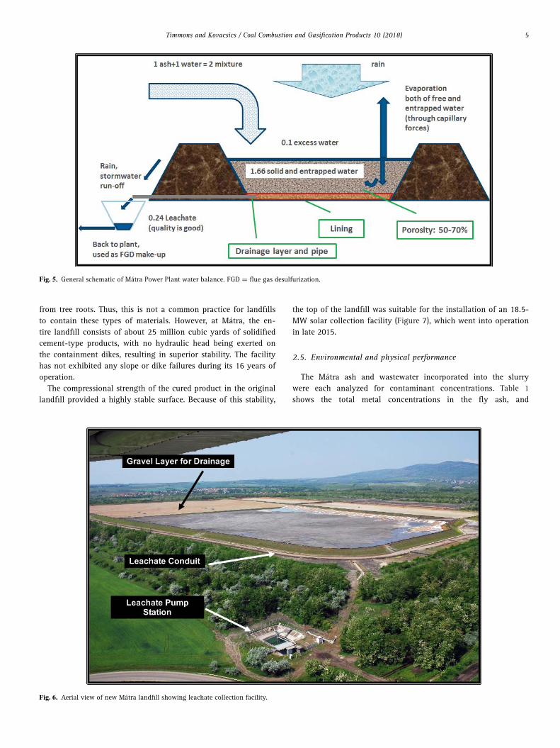
The new landfill is shown in Figure 6. It replaced the landfill de-picted in Figure 3, which was subsequently closed. The new landfillconsists of four cells. Consistent with the operation of the previouslandfill, one cell receives slurry from the plant, and the other threecells are in various stages of preparation. The new landfill is de-signed for disposal of ash for the remaining life of the Matra Plant.
2.4. Other advantages realized from deploying DSS
The considerable water savings mentioned earlier resulted in adramatic reduction in the amount of water that needed to be movedfrom one place to another. This reduced power consumption relatedto ash and wastewater management by approximately 80%.
Acacia trees were planted on the slopes of the closed landfill toenhance slope stability, reduce erosion, and absorb surface water.The integrity of dikes surrounding impoundments and landfills thatcontain materials susceptible to liquefaction can be compromised

4 Timmons and Kovacsics / Coal Combustion and Gasification Products 10 (2018)
Fig. 3. Summary of Circumix dense slurry application. FGD = flue gas desulfurization.
Fig. 4. Dense slurry system landfill consisting of fifteen 10-ft-thick (3-m-thick) tiers. The top of the landfill comprises six cells covering an area of about 200 acres(81 ha).
Timmons and Kovacsics / Coal Combustion and Gasification Products 10 (2018) 5
Fig. 5. General schematic of Matra Power Plant water balance. FGD = flue gas desulfurization.
from tree roots. Thus, this is not a common practice for landfillsto contain these types of materials. However, at Matra, the en-tire landfill consists of about 25 million cubic yards of solidifiedcement-type products, with no hydraulic head being exerted onthe containment dikes, resulting in superior stability. The facilityhas not exhibited any slope or dike failures during its 16 years ofoperation.
The compressional strength of the cured product in the originallandfill provided a highly stable surface. Because of this stability,
the top of the landfill was suitable for the installation of an 18.5-MW solar collection facility (Figure 7), which went into operationin late 2015.
2.5. Environmental and physical performance
The Matra ash and wastewater incorporated into the slurrywere each analyzed for contaminant concentrations. Table 1shows the total metal concentrations in the fly ash, and
Fig. 6. Aerial view of new Matra landfill showing leachate collection facility.
6 Timmons and Kovacsics / Coal Combustion and Gasification Products 10 (2018)
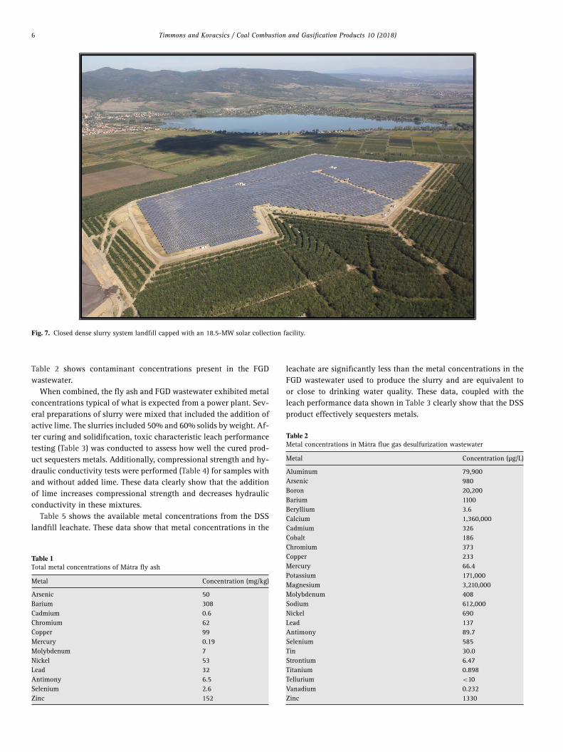
Fig. 7. Closed dense slurry system landfill capped with an 18.5-MW solar collection facility.
Table 2 shows contaminant concentrations present in the FGDwastewater.
When combined, the fly ash and FGD wastewater exhibited metalconcentrations typical of what is expected from a power plant. Sev-eral preparations of slurry were mixed that included the addition ofactive lime. The slurries included 50% and 60% solids by weight. Af-ter curing and solidification, toxic characteristic leach performancetesting (Table 3) was conducted to assess how well the cured prod-uct sequesters metals. Additionally, compressional strength and hy-draulic conductivity tests were performed (Table 4) for samples withand without added lime. These data clearly show that the additionof lime increases compressional strength and decreases hydraulicconductivity in these mixtures.
Table 5 shows the available metal concentrations from the DSSlandfill leachate. These data show that metal concentrations in the
Table 1Total metal concentrations of Matra fly ash
Metal Concentration (mg/kg)
Arsenic 50Barium 308Cadmium 0.6Chromium 62Copper 99Mercury 0.19Molybdenum 7Nickel 53Lead 32Antimony 6.5Selenium 2.6Zinc 152
leachate are significantly less than the metal concentrations in theFGD wastewater used to produce the slurry and are equivalent toor close to drinking water quality. These data, coupled with theleach performance data shown in Table 3 clearly show that the DSSproduct effectively sequesters metals.
Table 2Metal concentrations in Matra flue gas desulfurization wastewater
Metal Concentration (μg/L)
Aluminum 79,900Arsenic 980Boron 20,200Barium 1100Beryllium 3.6Calcium 1,360,000Cadmium 326Cobalt 186Chromium 373Copper 233Mercury 66.4Potassium 171,000Magnesium 3,210,000Molybdenum 408Sodium 612,000Nickel 690Lead 137Antimony 89.7Selenium 585Tin 30.0Strontium 6.47Titanium 0.898Tellurium <10Vanadium 0.232Zinc 1330

Timmons and Kovacsics / Coal Combustion and Gasification Products 10 (2018) 7
Table 3Toxic characteristic leach performance testing of prepared Matra ash and flue gasdesulfurization (FGD) mixes
Sample ID
2.5% lime service 2.5% lime FGD 5% lime service 5% lime FGDComponent water (mg/kg) water (mg/kg) water (mg/kg) water (mg/kg)
pH 11.1 11.0 10.8 11.3Arsenic 0.19 0.06 0.15 0.04Barium 0.51 1.87 0.20 0.51Cadmium <0.01 <0.01 <0.01 <0.01Chromium 0.07 0.07 0.14 0.05Copper <0.03 <0.03 <0.03 <0.03Mercury <0.05 <0.05 <0.05 <0.05Molybdenum 0.32 0.17 0.96 0.17Nickel <0.03 <0.03 <0.03 <0.03Lead <0.03 <0.03 <0.03 <0.03Antimony 0.07 0.06 0.14 0.03Selenium <0.05 <0.05 <0.01 <0.05Zinc 0.06 0.05 0.12 0.06
Table 4Compressional (Comp.) strength and hydraulic conductivity (H/C) of curedsamples
Sample ID
Comp.strength(psi)
H/C (1)(cm/s)
H/C (2)(cm/s)
H/C (3)(cm/s)
Average(cm/s)
60 wt% solids,no additive 7 5.7 × 10⁻⁵ 1.9 × 10⁻⁵ 1.3 × 10⁻⁵ 3.0 × 10⁻⁵
50 wt% solids,2.5 wt% CaO 188 5.9 × 10⁻⁶ 3.3 × 10⁻⁶ 1.1 × 10⁻⁶ 3.4 × 10⁻⁶
3. Summary
The Matra Power Plant in Hungary replaced a lean slurry ashhandling system with a DSS more than 16 years ago to reduce wa-ter consumption and operating costs. DSS was also employed toeliminate fugitive dust pollution and minimize other environmen-tal impacts associated with ash and wastewater management.
Employment of the DSS technology reduced water consumptionfor the ash handling and FGD systems by 80%. The technology alsoreduced operation and maintenance costs significantly, and fugitivedust problems have been eliminated. Most of the contaminants con-tained in the FGD wastewater and fly ash that comprise the slurry
Table 5Leachate quality compared with water regulatory standards
Drinking Surface LeachateComponent water limits water limits returned to plant
Cadmium (μg/L) 5 5 <2Lead (μg/L) 10 50 <5Nickel (μg/L) 20 100 5–11Zinc (μg/L) — 500 10–12Chloride (mg/L) 250 — 177–519Conductivity (μS/cm) 2500 — 3300–3464pH 6.5–9.5 6–9.5 7.3–7.7Manganese (μg/L) 50 2000 19–260Sulfate (mg/L) 250 20 1404–1670Copper (mg/L) 2 0.1 0.08–0.16Sodium (mg/L) 200 — 94–130
were sequestered in the cured product. The leachate produced bythe DSS landfill is of sufficient quality to be reused in the powerplant.
Employing DSS at Matra is the predominant reason that the planthas achieved ZLD status, and it has been a successful solution forash and wastewater management. The ash landfill was closed andnow supports a solar collection facility that generates 18.5 MW ofelectricity. A new disposal facility was built and commissioned toreplace the closed facility, which will significantly extend the usefullife of the plant.
NAES Corporation and Enexio Hungary Zrt. have teamed to de-ploy the Circumix DSS technology in North America. In 2014, NAESand Enexio executed an agreement that appointed NAES the exclu-sive representative for the DSS technology in North America. NAEShas since been working with selected coal-fired power plants, pri-marily in the United States, that can realize the greatest economicand regulatory benefits by deploying DSS. For more information,please contact NAES.
References
American Coal Ash Association, 2016. 2015 Production and Use Survey Results,New Release.
Hill, D., Bozek, R., 2016. Overview of Final ELG Rule: Standards and Timing.Presented at the USWAG CCR Workshop, Washington, DC, February 2016.