Embed Size (px)
Citation preview

ICS Regent® PD-6024
Industrial Control Services 1
Thermocouple Input Assembly
Input Module, Mux, Termination Panel and Cable (T3431-IM, T3431-Mux, T3431-TP and T3431-CA)
Issue 1, March, 06
The thermocouple input assembly consists of a thermocouple input module (T3431-IM), a thermocouple input multiplexer (T3431-MUX), a thermocouple termination panel (T3431-TP), and a thermocouple termination cable (T3431-CA). This equipment provides terminations and temperature conversion for as many as 24 thermocouple inputs, arranged in 3 groups of eight inputs.
Features
· Twenty-four thermocouple inputs.
· Configuration options: Thermocouple type: J, K, S, T (in groups of eight) Units: Degrees F or degrees C Resolution: Units or tenths Filter response: 50 Hz, 60Hz rejection
· Complete linearization, cold junction compensation and automatic calibration.
· Remote terminations up to 50 cable feet from I/O chassis.
· 2500 volt isolation between Input Module and Mux.
· High speed acquisition.
· Hot-replaceable input module and Mux.
· Extensive fault diagnostics.
· Thermocouple burnout detection (downscale).
· TÜV certified, Risk Class 5, non-interfering.
The input module plugs into an I/O chassis slot and receives data from the thermocouple input multiplexer (or Mux). The thermocouple input multiplexer plugs into the termination panel and provides low level signal conditioning,

Thermocouple Input Assembly (T3431)
2 Industrial Control Services
multiplexing, and analog-to-digital conversion. The termination panel can be located as far as 50 cable feet from the I/O chassis.
Each module’s triplicated I/O Safetybus interface ensures that no failure in the module can affect the operation of the Regent system or other I/O modules in the system. Extensive fault detection and annunciation of critical redundant circuits help prevent the controllers from receiving erroneous data from a faulty input module. The fault tolerant boundary may be extended by using three input modules and three termination panels. A single thermocouple is wired to three different termination panels for fault tolerance. The fault tolerant boundary may be further extended into the process by wiring three separate thermocouples, all measuring the same process parameter, to three separate termination panels. In either triplicated configuration, a failed module or multiplexer can be removed and replaced without interrupting the input signals.
Module Operation
A simplified block diagram of the thermocouple input assembly is shown in Figure 1.
Thermocouples are terminated at the termination panel. The termination panel routes the thermocouple signals to the Mux for multiplexing, signal conditioning, and A to D conversion. The Mux also senses the cold junction sensor voltages. Cold junction sensors are mounted on the termination panel near the screw terminations.
The termination cable connects the termination panel to the input module. A DC-to-DC converter on the input module shares three power legs from the I/O backplane power and provides isolated power to the Mux over the termination cable. The Mux transmits digitized serial thermocouple data back to the input module. The maximum allowable cable length is 50 feet.

Thermocouple Input Assembly (T3431)
P D - 6 0 2 4 M a r - 0 6 3
Figure 1. Block Diagram of the Thermocouple Input Assembly.
The Serial data received from the Mux is optically coupled at the input module to provide electrical isolation. The input module's 68000-based microcomputer processes the thermocouple data. This microcomputer’s functions include:
· Digital filtering
· Automatic calibration
· Cold junction compensation
· Temperature conversion and linearization
· Diagnostics
The processor modules send triplicated read data requests to the thermocouple input module over the I/O Safetybus. The processors’ addressing data and data read requests are voted by the module (preventing I/O Safetybus failures upstream from the module from affecting module operations). The voted result is then passed to the I/O bus interface logic.

Thermocouple Input Assembly (T3431)
4 Industrial Control Services
After receiving the voted data read request, the microcomputer transmits the conditioned temperature data to the Safetybus interface. This interface places the voted temperature data onto the triplicated Safetybus bus drivers. Each of the three bus drivers is independently powered and controlled (by the I/O transceiver modules) — preventing failures in a single driver from propagating to the other two I/O busses. The bus drivers then transmit the data via the backplane I/O Safetybus to the I/O transceiver modules which, in turn, transmit the data to the processors.
The thermocouple input data is packaged as a 16-bit word for each input. The format of each word is shown in Figure 2. The most significant bit in the word is used as an alarm bit to indicate an out-of-range thermocouple input signal. The remaining 15 bits contain signed 15-bit integer data representing the temperature in degrees C or F and in units or tenths of degrees, as configured by jumper settings on the Mux.
Figure 2. Thermocouple Input Data Format.
Testing and Diagnostics
Input Module Testing
Each module’s voter circuits are periodically tested by the processor modules. Discrepant data are sent through one of three legs of the I/O Safetybus to determine whether the module’s voter is able to outvote the incorrect data. A failure to return the correct majority-voted result to the processors produces an I/O module error indication at the processor modules and a module fault indication at the I/O module.
Thermocouple Input Assembly (T3431)
P D - 6 0 2 4 M a r - 0 6 5
Each type of module has a unique identification code that is read by the controller. This code lets the controller know which type of module is installed in each I/O chassis slot and how to address that module and its points specifically. If a module is removed, or is replaced with a module of a different type, the processor modules will indicate an I/O module error.
Loopback logic tests periodically write data to the module and then read it back to determine whether the module’s I/O bus interface logic is functioning correctly.
Multiplexer Testing
The serial communications link to the thermocouple Mux is continuously monitored. Additionally the data received from the Mux is checked for proper data format, parity and numeric range reasonableness. The cold junction sensor values are monitored and compared to detect a failed cold junction sensor. The precision voltage references on the multiplexer are also checked to verify that the power to the Mux is present and that the voltage references are within tolerance.
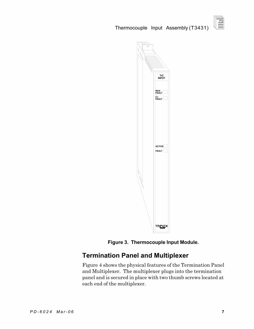
Input Module Front Panel Indicators
Figure 3 shows the physical features of the thermocouple input module. The front panel of each module contains status indicators to display the operational status of the input module, multiplexer and cold junction sensors.
Active and Fault Status Indicators
These green and red LEDs indicate the overall health of the module. During normal operation the green ACTIVE indicator flashes at the controller's scan rate. If a module fault occurs the red FAULT indicator turns on and the green ACTIVE indicator turns off.
MUX Fault Indicator
The red MUX FAULT indicator turns on when any of the following fault conditions are detected:
· No data received from the Mux.
· Corrupted data from the Mux.
· Unreasonable data values from the Mux.

Thermocouple Input Assembly (T3431)
6 Industrial Control Services
Failure of the DC-to-DC converter supplying power to the termination panel or the receiver circuitry can also result in a MUX fault. Both of these faults are input module faults.
CJ Fault Indicator
There are two cold junction sensors located on the termination panel. The red CJ FAULT indicator turns on when any of the following fault conditions are detected:
· Either CJ sensor temperature is < -5° C (23° F)
· Either CJ sensor temperature is > 65° C (149° F)
· The CJ sensors differ by more than 2.8° C (5° F)
Thermocouple Input Assembly (T3431)
P D - 6 0 2 4 M a r - 0 6 7
Figure 3. Thermocouple Input Module.
Termination Panel and Multiplexer
Figure 4 shows the physical features of the Termination Panel and Multiplexer. The multiplexer plugs into the termination panel and is secured in place with two thumb screws located at each end of the multiplexer.

Thermocouple Input Assembly (T3431)
8 Industrial Control Services
The termination cable plugs into the DB-9 connector located at the upper right corner of the termination panel. Thermocouple inputs are terminated at the screw terminals located along the bottom of the termination panel. These terminals are arranged in three groups of eight inputs. Two screw terminals are provided for each thermocouple input. Two additional ground terminals within each group are provided to connect thermocouple cable shield wires if desired.
Termination Panel Indicators
The termination panel has status indicators for power supply voltages, and transmit data. When positive and negative supply voltages are present at the termination panel, the POWER + and POWER - indicators are on. The TX DATA indicator is on when the Mux is transmitting data to the input module. Normally, all these green indicators should be on.

Thermocouple Input Assembly (T3431)
P D - 6 0 2 4 M a r - 0 6 9
Figure 4. Thermocouple Termination Panel and Multiplexer.

Thermocouple Input Assembly (T3431)
1 0 Industrial Control Services
Application
Simplex Configuration
Thermocouple input modules provide a suitable interface to non-critical input signals. Although many of the circuits in the thermocouple input module and multiplexer are automatically tested and annunciated, some logic circuits and most of the field-side sensing circuits are simplex and non-tested. This simplex input configuration is illustrated in Figure 5.
Figure 5. Simplex Thermocouple Input Configuration.
Fault Tolerant Configurations
For critical inputs, redundant input modules, multiplexers and termination panels are used in a 2oo3 or 1oo2 fault tolerant configuration. In these configurations the redundant thermocouple input equipment is connected to single or multiple thermocouples. If redundant thermocouples are installed in the field, each thermocouple connects to one termination panel, multiplexer and input module. These configurations are illustrated in Figure 6, showing triple redundant input modules. Each thermocouple input module, cable, term panel and multiplexer is hot replaceable. In redundant input configurations, if a fault occurs in one set of equipment, the failed equipment can be removed and replaced

Thermocouple Input Assembly (T3431)
P D - 6 0 2 4 M a r - 0 6 11
while the system continues to sense the inputs from the remaining two sets of equipment.
Figure 6. Fault Tolerant Thermocouple Input Configurations.

Thermocouple Input Assembly (T3431)
1 2 Industrial Control Services
Thermocouple Multiplexer Configuration
The thermocouple input multiplexer provides jumpers to configure the thermocouple types, noise filtering, temperature units, and temperature resolution. All thermocouple configuration jumpers are located on the component side of the Mux as shown in Figure 7. To access these jumpers the Mux must be removed from the termination panel.
Figure 7. Location of Configuration Jumpers on Mux.
Thermocouple Type Configuration
Each group of eight inputs, 1-8, 9-16, and 17-24, is individually configured for thermocouple type J, K, S, or T using three jumpers for each group of inputs. The three jumpers are labeled Bit 4, Bit 2 and Bit 1. The jumper settings for each thermocouple type are shown in Table 1.
Table 1. Thermocouple Type Jumper Settings.
Thermocouple Type Bit 4 Bit 2 Bit 1
J Low Low Low
K Low Low High
S High Low Low
T High Low High
To assign the thermocouple type, find the associated jumper block for the group T/C 1-8, T/C 9-16, or T/C 17-24 and place each jumper next to the appropriate high or low designation.
Thermocouple Input Assembly (T3431)
P D - 6 0 2 4 M a r - 0 6 13
Note: There are four unused codes. Using any of these codes will cause a Mux fault indication.
Thermocouple Noise Filtering
Thermocouples and their associated wiring may be installed in electrically noisy environments. Noise filtering is required to ensure that this noise does not affect the reading of the low level thermocouple signals. Three jumper posts are located on the Mux to select between 50 Hz or 60 Hz digital filtering.
Choose the frequency which represents the predominant source of electrical noise in the thermocouple environment (e.g. electrical motors). This configuration selection applies to all 24 thermocouple inputs. Position the jumper on the upper two posts to select 50 Hz filtering. Position the jumper on the lower two posts to select 60 Hz filtering.
Thermocouple Data Format
The thermocouple input module provides linearized temperature data to the processors in degrees Fahrenheit or Celsius. Three jumper posts are located on the Mux to select between degrees C or F. Position the jumper on the upper two posts to select degrees C. Position the jumper on the two lower posts to select degrees F.
The temperature data resolution must also be configured for units (data increments of 1 degree), or tenths (data increments of 0.1 degree). Position the jumper on the upper two posts to select units. Position the jumper on the two lower posts to select tenths.
Note: the thermocouple data is always presented as integer data to the processor modules. When you select tenths resolution, there is an implied fixed place decimal before the least significant digit in the temperature data. For example the temperature data value 1527 would represent 152.7º.
The ranges of temperature data for each type of thermocouple are shown in Table 2. The thermocouple data format selections apply to all 24 thermocouple inputs.
Table 2. Temperature Data Ranges
Maximum Range Limits
Resolution: 1º Resolution: 0.1º

Thermocouple Input Assembly (T3431)
1 4 Industrial Control Services
T/C Type
Scale Lower Limit
Upper Limit
Lower Limit
Upper Limit
Lower Limit
Upper Limit
J ºC 0 750 0 750 0.0 750.0
ºF 32 1382 32 1382 32.0 1382.0
K ºC -200 1250 -200 1250 -200.0 1250.0
ºF -328 2282 -328 2282 -328.0 1638.3
S ºC 0 1450 0 1450 0.0 1450.0
ºF 32 2642 32 2642 32.0 1638.3
T ºC -200 350 -200 350 -200.0 350.0
ºF -328 662 -328 662 -328.0 662.0
Note for thermocouple types K and S: If a 0.1° F resolution is selected, the maximum usable temperature is 1638.3° F. Even though the range limit has not been reached, the value will be clamped at 1638.3 because of word length limitations. Changing the resolution jumper to units will allow the entire data range to be passed without clamping.
Thermocouple Burnout Detection
Open thermocouple channels are automatically driven downscale (downscale burnout). The temperature value will be equal to the lower limit value for the particular thermocouple type. An open circuit on either terminal will cause a downscale reading. This is not affected by a ground connection at the thermocouple.
In application programming, the NOSIG contact in ladder logic can be used to sense the thermocouple burnout condition. For more information, see Programming, starting on page 21.
Installation Planning
Accuracy Considerations
Use the following guidelines to maximize overall system accuracy:
1. Temperature gradients should be minimized at the termination panel. Avoid forced air cooling or placing heat dissipating components directly underneath the terminal

Thermocouple Input Assembly (T3431)
P D - 6 0 2 4 M a r - 0 6 15
block areas. Install the thermocouple terminations cover provided with the termination panel. Allow at least four hours for temperature stabilization after any significant temperature change.
2. If possible, terminate unused input channels with the same thermocouple signal as the next channel, or short the terminals of the unused input. This will minimize the pulling affect of a preceding input.
3. Minimize the resistance of the thermocouple extension wire by using heavier wire gauges.
Radiated Field Susceptibility
Transmitting equipment should not be operated within the vicinity of the termination panel. Power levels greater than one watt at a distance of one foot may degrade thermocouple measurements and eventually cause a permanent fault to be logged, resulting in a shutdown (clear to 0) of all inputs on the affected panel.
Grounding
The termination panel should be connected to the system’s safety or system ground. Use a minimum of #18 stranded wire. A chassis ground terminal is provided for this purpose. It is located underneath the wire cover near thermocouple input 24.
Additional ground terminals are provided at either end of each terminal block group. These terminals are electrically connected to the chassis and can be used for thermocouple shield terminations.
Installing the Termination Panel
The thermocouple termination panel can be mounted in a 19-inch rack or flush mounted to a panel. Refer to Figure 8 for overall mounting dimensions for the termination panel and Mux.

Thermocouple Input Assembly (T3431)
1 6 Industrial Control Services
Figure 8. Mounting Dimensions for the Termination Panel.
Termination Panel Cable
The termination panel cable connects the input module to the termination panel. It carries power to the panel and routes serial data to the input module. One end of the cable has a male DB-9 nine-pin connector that plugs into the termination panel. The opposite end should be cut to the desired length and wired to the I/O chassis terminal block immediately above the input module. Do not connect the shield wire at this end. The six wires in the cable are connected to the I/O slot terminals as shown in Figure 9.

Thermocouple Input Assembly (T3431)
P D - 6 0 2 4 M a r - 0 6 17
Figure 9. Termination Cable Connections.
Thermocouple Input Assembly (T3431)
1 8 Industrial Control Services
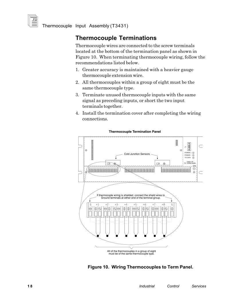
Thermocouple Terminations Thermocouple wires are connected to the screw terminals located at the bottom of the termination panel as shown in Figure 10. When terminating thermocouple wiring, follow the recommendations listed below.
1. Greater accuracy is maintained with a heavier gauge thermocouple extension wire.
2. All thermocouples within a group of eight must be the same thermocouple type.
3. Terminate unused thermocouple inputs with the same signal as preceding inputs, or short the two input terminals together.
4. Install the termination cover after completing the wiring connections.
Figure 10. Wiring Thermocouples to Term Panel.

Thermocouple Input Assembly (T3431)
P D - 6 0 2 4 M a r - 0 6 19
Keying
The I/O chassis can be physically keyed to prevent accidental damage caused by inserting a module into a slot wired for a different module type. Figure 11 illustrates how the slot keys are installed on the I/O chassis slot field wiring connectors. The slot key positions for the thermocouple input module is listed in Table 3.
Figure 11. Installing Slot Keys.

Thermocouple Input Assembly (T3431)
2 0 Industrial Control Services
Table 3. Slot Key Positions.
Module Upper Connector
Lower Connector
T3431 15 15
Configuration
Each input module is configured using the WINTERPRET I/O Configuration Editor. In the editor, you will perform the three steps described below to configure the input module.
1) Set the Module Type:
Position the cursor on the module slot you wish to define. Choose Set Module Type from the Edit Menu and select the thermocouple input module from the list.
2) Edit the Module Definition:
Choose Edit Module Definition from the Edit Menu. A dialog box will open where you can define the input point definitions.
Figure 12. Thermocouple Input Module Definition.
3) Edit each point:
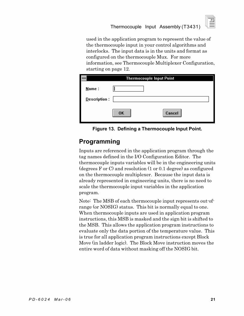
Position the cursor on a Point definition and choose Edit from the Module Definition dialog box to define a name and description for each input point. In the Thermocouple Input Point dialog, enter a tag name (up to 12 characters) and a description (up to 40 characters). The tag names are
Thermocouple Input Assembly (T3431)
P D - 6 0 2 4 M a r - 0 6 21
used in the application program to represent the value of the thermocouple input in your control algorithms and interlocks. The input data is in the units and format as configured on the thermocouple Mux. For more information, see Thermocouple Multiplexer Configuration, starting on page 12.
Figure 13. Defining a Thermocouple Input Point.
Programming
Inputs are referenced in the application program through the tag names defined in the I/O Configuration Editor. The thermocouple inputs variables will be in the engineering units (degrees F or C) and resolution (1 or 0.1 degree) as configured on the thermocouple multiplexer. Because the input data is already represented in engineering units, there is no need to scale the thermocouple input variables in the application program.
Note: The MSB of each thermocouple input represents out-of-range (or NOSIG) status. This bit is normally equal to one. When thermocouple inputs are used in application program instructions, this MSB is masked and the sign bit is shifted to the MSB. This allows the application program instructions to evaluate only the data portion of the temperature value. This is true for all application program instructions except Block Move (in ladder logic). The Block Move instruction moves the entire word of data without masking off the NOSIG bit.

Thermocouple Input Assembly (T3431)
2 2 Industrial Control Services
Programming Fault Tolerant Thermocouple Inputs
To program fault tolerant configurations using triplicated thermocouple input modules, a midvalue element can be used as shown in Figure 14.
Figure 14. Programming Fault Tolerant Thermocouple Inputs.
In this illustration, VALUE_A_NAME, VALUE_B_NAME, and VALUE_C_NAME represent the three thermocouple inputs to be mid-value selected. ERROR_A_NAME, ERROR_B_NAME and ERROR_C_NAME are the error bits for the T/C inputs. RESULT_NAME is the result of the mid-value instruction. The field Limit is the integer value, in similar units to the Value A, B and C variables, that a thermocouple input can deviate from the mid-value result before signaling an error (via the Error A, B or C bits). Once an error bit is set, it is latched. RESET_NAME is the reset bit used to reset the latched error bits.
Thermocouple Burnout and Out of Range Conditions
The NOSIG contact in ladder logic function blocks can be used to detect an out of range thermocouple input signal. The NOSIG contact will be true if the thermocouple input reaches the limits of its usable range (see Table 2, Temperature Data Ranges). The temperature value will be equal to the lower or upper limit value listed in the table for maximum data range while the temperature remains out of range.
Note: For Type K and S thermocouples, the maximum input value is clamped at 16383 due to data format limitations. The NOSIG contact will not be true until the thermocouple signal reaches the maximum upper limit value defined in Table 2.

Thermocouple Input Assembly (T3431)
P D - 6 0 2 4 M a r - 0 6 23
Maintenance
Calibration
The Mux contains an ultra-stable voltage reference circuit for auto-calibration of all thermocouple channels. This circuit does not require re-adjustment.
Cold junction sensors do not require re-adjustment.
Troubleshooting
The following procedure is used for troubleshooting the thermocouple input. The only assumption made is that the input module fault indicator is on.
1. If both the Mux and CJ indicators are off, replace the input module.
2. If only the Mux indicator is on, check the termination panel’s status indicators.
If either POWER indicator is off, verify that the termination panel cable is connected and that the cable connections at the I/O chassis are correct (refer to Figure 9). Replace the input module.
If the POWER indicators remain off, replace the Mux.
If both POWER indicators are on but the TX DATA indicator is off, replace the Mux.
If both the POWER and TX DATA indicators are lit, replace the Mux. If the Mux indicator is still on, replace the input module.
3. If only the CJ indicator is on, check that the temperature at the termination panel is between 0° and 60° C and that there are no significant thermal gradients present.
Remove the Mux and check for damaged cold junction sensors. The sensors are mounted to the termination panel directly above the terminal block area.
If the sensors are not damaged, replace the Mux. If the CJ indicator is still on, consult ICS for CJ sensor replacement procedures and parts.
Thermocouple Input Assembly (T3431)
2 4 Industrial Control Services
Safety Considerations
The thermocouple input modules are TÜV certified as non-interfering and can be used for non-safety critical inputs in Risk Class 5 safety applications.
For additional safety considerations, please refer to the Safety Considerations section of the Regent User’s Guide.
Specifications
Safetybus Power 1.8 load units (input module)
Number of Inputs 24 differential
Thermocouple Input Types Type J: Type K: Type S: Type T:
Iron/constantan Chromel/alumel Pt/Pt-10% Rh Copper/constantan
Thermocouple Units Degrees Centigrade or degrees Fahrenheit
Thermocouple Resolution Tenths or units
Thermocouple Ranges Type J: Type K: Type S: Type T:
0° to +750° C (+32° to +1382° F) -200° to +1250° C (-328° to +2282° F)* 0° to +1450° C (+32° to +2642° F)* -200° to +350° C (-328° to +662° F) * If 0.1° F resolution is selected,
the maximum usable temperature is +1638.3° F
Thermocouple Burnout Downscale driven
Differential Input Resistance 2M ohms (typical)

Thermocouple Input Assembly (T3431)
P D - 6 0 2 4 M a r - 0 6 25
Input to Chassis Resistance 1.1M ohm (typical)
Bias Current 100 nA (typical)
Common Mode Operating Range
7 volts, maximum w/r chassis ground
Input Over voltage Protection
120 volts RMS between any two terminals
Response Time (Total) Step Input:
Ramp Input:
50 msec maximum (0 to 99%)
25 msec maximum tracking delay for input rates less than 8° C/ms (15° F)
Noise Rejection (Conducted) Normal Mode: Common Mode:
70 dB minimum at 60/120 Hz or 50 Hz (jumper selectable)
100 dB minimum at 50/60 Hz, 60 dB minimum elsewhere
Noise Rejection (Radiated)
Walkie-talkie:
0.1% (range) maximum error for 1 watt at 1 foot from Mux (any polarization)

Thermocouple Input Assembly (T3431)
2 6 Industrial Control Services
Thermocouple Accuracy Maximum error (0° to 60° C). Add ±0.5 LSB resolution error to the following: Type J, Full range: Type K < -100° C:
> -100° C: Type S < 540° C:
> 540° C: Type T < 0° C:
> 0° C:
±1.6° C (3.0° F) ±4.2° C (7.6° F) ±2.4° C (4.3° F) ±13° C (24° F) ±7° C (12.5° F) ±4.8° C (8.7° F) ±2.1° C (3.8° F)
Wire Resistance Effects Type J, Full range: Type K < -100° C:
> -100° C: Type S < 540° C:
> 540° C: Type T < 0° C:
> 0° C:
-0.0020° C/ohm (.0036° F) -0.0066° C/ohm (0.0120° F) -0.0033° C/ohm (0.0060° F) -0.0200° C/ohm (0.0360° F) -0.0100° C/ohm (0.0180° F) -0.0066° C/ohm (0.0120° F) -0.0025° C/ohm (0.0045° F)
Adjacent Channel Effects Channel n = top of range channel; n-1 = bottom of range Type J: Type K: Type S: Type T:
-1.0° C (1.7° F) -1.5° C (2.7° F) -4.0° C (7.2° F) -0.8° C (1.5° F)
Channel n = bottom of range; n-1 = open circuit Type J: Type K: Type S: Type T:
-3.0° C (5.4° F) -4.0° C (7.2° F) -30° C (54° F) -4.5° C (8.1° F)

Thermocouple Input Assembly (T3431)
P D - 6 0 2 4 M a r - 0 6 27
Termination Panel Cable Length
Maximum 50 cable feet (15 m)
Isolation 2500 volts minimum (field wiring to control logic)
Operating Temperature 0° to 60° C (32° to 140° F)
Storage Temperature -40° to 85° C (-40° to 185° F)
Operating Humidity 0 to 95% relative humidity, non-condensing
Safety Certified to DIN V VDE 0801 (non-interfering) and designed to meet UL 508 and CSA 22.2, No. 142-M1981
Heat Dissipation Input module: Termination panel/Mux:
4.5 Watts, 15 BTUs/hour 2.5 Watts, 9 BTUs/hour
Dimensions Input Module Height: Width: Depth: Termination Panel Height: Width: Depth: Mux Height: Width: Depth:
12.6” (320 mm) 1.27” (32 mm) 10.125” (257 mm) 6.94” (176 mm) 19.0” (483 mm) 2.25” (57.2 mm) 4.5” (114 mm) 15.0” (381 mm) 1.25” (31.8 mm)
Weight Input module: Mux: Termination panel:
3.5 lbs (1.6 kg) 2 lbs (0.9 kg) 5.6 lbs (2.5 kg)