Embed Size (px)
Citation preview
ControlLogix Ethernet Communication Interface Module1756-ENET/B
User Manual

Important User Information Because of the variety of uses for the products described in this publication, those responsible for the application and use of this control equipment must satisfy themselves that all necessary steps have been taken to assure that each application and use meets all performance and safety requirements, including any applicable laws, regulations, codes and standards.
The illustrations, charts, sample programs and layout examples shown in this guide are intended solely for purposes of example. Since there are many variables and requirements associated with any particular installation, Allen-Bradley does not assume responsibility or liability (to include intellectual property liability) for actual use based upon the examples shown in this publication.
Allen-Bradley publication SGI-1.1, Safety Guidelines for the Application, Installation and Maintenance of Solid-State Control (available from your local Allen-Bradley office), describes some important differences between solid-state equipment and electromechanical devices that should be taken into consideration when applying products such as those described in this publication.
Reproduction of the contents of this copyrighted publication, in whole or part, without written permission of Rockwell Automation, is prohibited.
Throughout this manual we use these notes to make you aware of safety considerations:
Warning and Attention statements help you to:
• identify a hazard
• avoid a hazard
• recognize the consequences
Allen-Bradley and ControlLogix are trademarks of Rockwell Automation.
Ethernet is a trademark of Digital Equipment Corporation, Intel, and Xerox Corporation.
RSLinx and RSLogix 5000 are trademarks of Rockwell Software.
Windows 95/98 and Windows NT are trademarks of Microsoft Corporation.
WARNING
!Identifies information about practices or circumstances that have the potential to create an explosion hazard.
ATTENTION
!Identifies information about practices or circumstances that can lead to personal injury or death, property damage or economic loss.
IMPORTANT Identifies information that is critical for successful application and understanding of the product.
European Communities (EC) Directive Compliance
If this product has the CE mark it is approved for installation within the European Union and EEA regions. It has been designed and tested to meet the following directives.
EMC Directive
This product is tested to meet the Council Directive 89/336/EC Electromagnetic Compatibility (EMC) by applying the following standards, in whole or in part, documented in a technical construction file:
• EN 50081-2 EMC — Generic Emission Standard, Part 2 — Industrial Environment
• EN 50082-2 EMC — Generic Immunity Standard, Part 2 — Industrial Environment
This product is intended for use in an industrial environment.
Low Voltage Directive
This product is tested to meet Council Directive 73/23/EEC Low Voltage, by applying the safety requirements of EN 61131-2 Programmable Controllers, Part 2 - Equipment Requirements and Tests. For specific information required by EN 61131-2, see the appropriate sections in this publication, as well as the Allen-Bradley publication Industrial Automation Wiring and Grounding Guidelines, publication 1770-4.1.
Open style devices must be provided with environmental and safety protection by proper mounting in enclosures designed for specific application conditions. See NEMA Standards publication 250 and IEC publication 529, as applicable, for explanations of the degrees of protection provided by different types of enclosure.

Rockwell Automation Support
Rockwell Automation offers support services worldwide, with over 75 sales/support offices, 512 authorized distributors and 260 authorized systems integrators located throughout the United States alone, as well as Rockwell Automation representatives in every major country in the world.
Local Product Support
Contact your local Rockwell Automation representative for:
• sales and order support
• product technical training
• warranty support
• support service agreements
Technical Product Assistance
If you need to contact Rockwell Automation for technical assistance, call your local Rockwell Automation representative, or call Rockwell directly at: 1 440 646-6800.
For presales support, call 1 440 646-3NET.
You can also obtain technical assistance online from the following Rockwell Automation WEB sites:
• www.ab.com/mem/technotes/kbhome.html (knowledge base)
• www.ab.com/networks/eds (electronic data sheets)
Your Questions or Comments on this Manual
If you find a problem with this manual, please notify us of it on the enclosed Publication Problem Report.

Preface
About This User Manual
What this Preface Contains This preface describes how to use this manual. The following table describes what this preface contains and where to find specific information.
Who Should UseThis Manual
This manual is intended for control engineers and technicians who are installing, programming, and maintaining a control system that communicates on an Ethernet network through a 1756-ENET/B module.
We assume you have a good understanding of Ethernet and the (TCP/IP) protocol. This user manual contains a brief description of Ethernet and TCP/IP in Chapter 3. For detailed information on TCP/IP protocol and networking in general, see the following publications:
• Comer, Douglas E. Internetworking with TCP-IP, Volume 1: Protocols and Architecture, 2nd ed. Englewood Cliffs, N.J.: Prentice-Hall, 1995. ISBN 0-13-216987-8.
• Tanenbaum, Andrew S. Computer Networks, 2nd ed. Englewood Cliffs, N.J.: Prentice-Hall, 1989. ISBN 0-13-162959-X.
For information about See pageWho Should Use This Manual P-1
Common Techniques Used in This Manual P-2
How To Use This Manual P-2
About the Example Applications P-3
System Components P-4
Where to Find More Information P-5
Terminology P-6
1 Publication 1756-UM051B-EN-P - November 2000
P-2 About This User Manual
Common TechniquesUsed in This Manual
The following conventions are used throughout this manual:
• Bulleted lists provide information, not procedural steps.
• Numbered lists provide sequential steps.
• Information in bold contained within text identifies menu windows, or screen options, screen names and areas of the screen, such as dialog boxes, status bars, radio buttons and parameters.
How To Use This Manual This manual provides an overview of the 1756-ENET/B module, as well as general information about Ethernet. It describes how to install and configure the module, and provides three example applications showing how to use the module to communicate over Ethernet.
The example applications are intended as building blocks to help you get your own network up and running. We recommend that you set up and run the example applications and use them as a guide for setting up your own system.
TIP This symbol identifies helpful tips.
A definition box defines terms that may be unfamiliar to you.
Screen captures are pictures of the software’s actual screens. The names of screen buttons and fields are often in bold in the text of a procedure. Pictures of keys represent the actual keys you press.
This is a definition box. When a word is bold within the text of a paragraph, a definition box will appear in the left margin to further define the text.
Publication 1756-UM051B-EN-P - November 2000
About This User Manual P-3
About the Example Applications
The example applications presented in this manual are as follows:
• Rack Optimized I/O (chapter 5)
• Using Analog I/O with Direct Connection (chapter 6)
• Produced and Consumed tags (chapter 7)
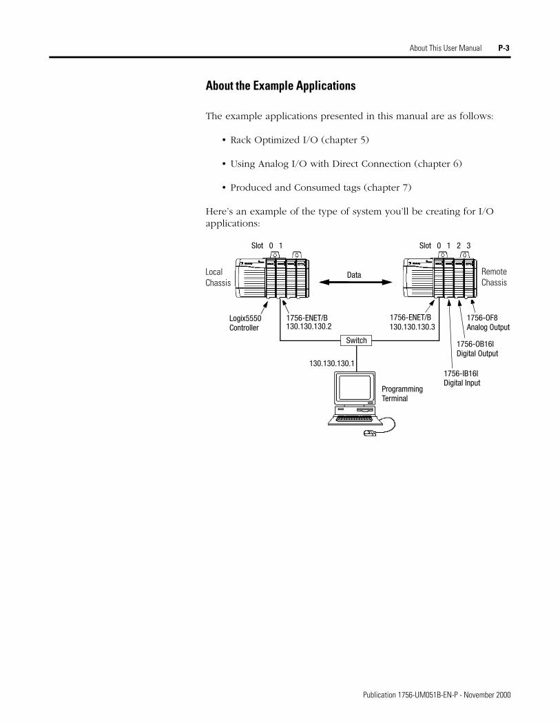
Here’s an example of the type of system you’ll be creating for I/O applications:
Logix5550 1756-ENET/B 1756-ENET/B
Data
Slot 0 1 Slot 0 1 2 3
1756-IB16IDigital Input
1756-OB16IDigital Output
Controller
Switch
Programming
130.130.130.1
130.130.130.2 130.130.130.3
Terminal
Local Chassis
Remote Chassis
1756-OF8Analog Output
Publication 1756-UM051B-EN-P - November 2000
P-4 About This User Manual
System Components
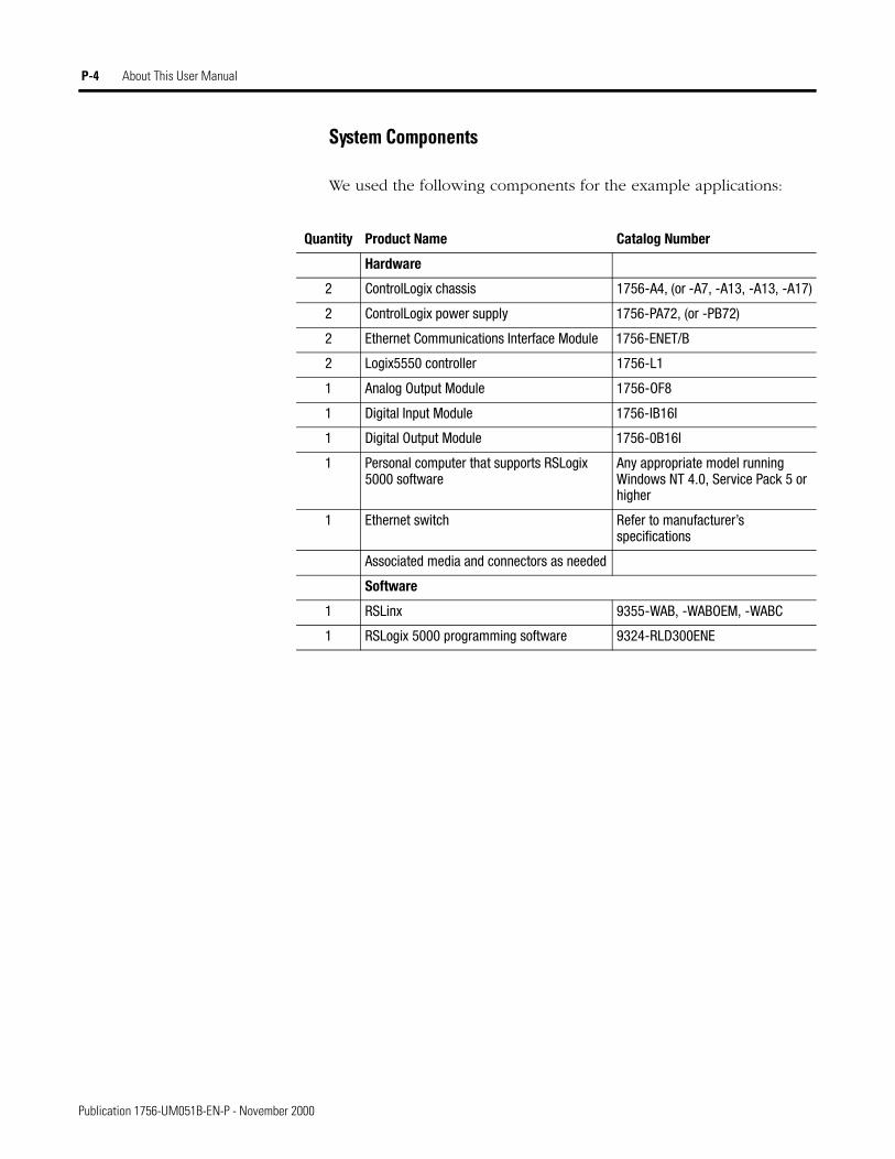
We used the following components for the example applications:
Quantity Product Name Catalog Number
Hardware
2 ControlLogix chassis 1756-A4, (or -A7, -A13, -A13, -A17)
2 ControlLogix power supply 1756-PA72, (or -PB72)
2 Ethernet Communications Interface Module 1756-ENET/B
2 Logix5550 controller 1756-L1
1 Analog Output Module 1756-OF8
1 Digital Input Module 1756-IB16I
1 Digital Output Module 1756-0B16I
1 Personal computer that supports RSLogix 5000 software
Any appropriate model running Windows NT 4.0, Service Pack 5 or higher
1 Ethernet switch Refer to manufacturer’s specifications
Associated media and connectors as needed
Software
1 RSLinx 9355-WAB, -WABOEM, -WABC
1 RSLogix 5000 programming software 9324-RLD300ENE
Publication 1756-UM051B-EN-P - November 2000
About This User Manual P-5
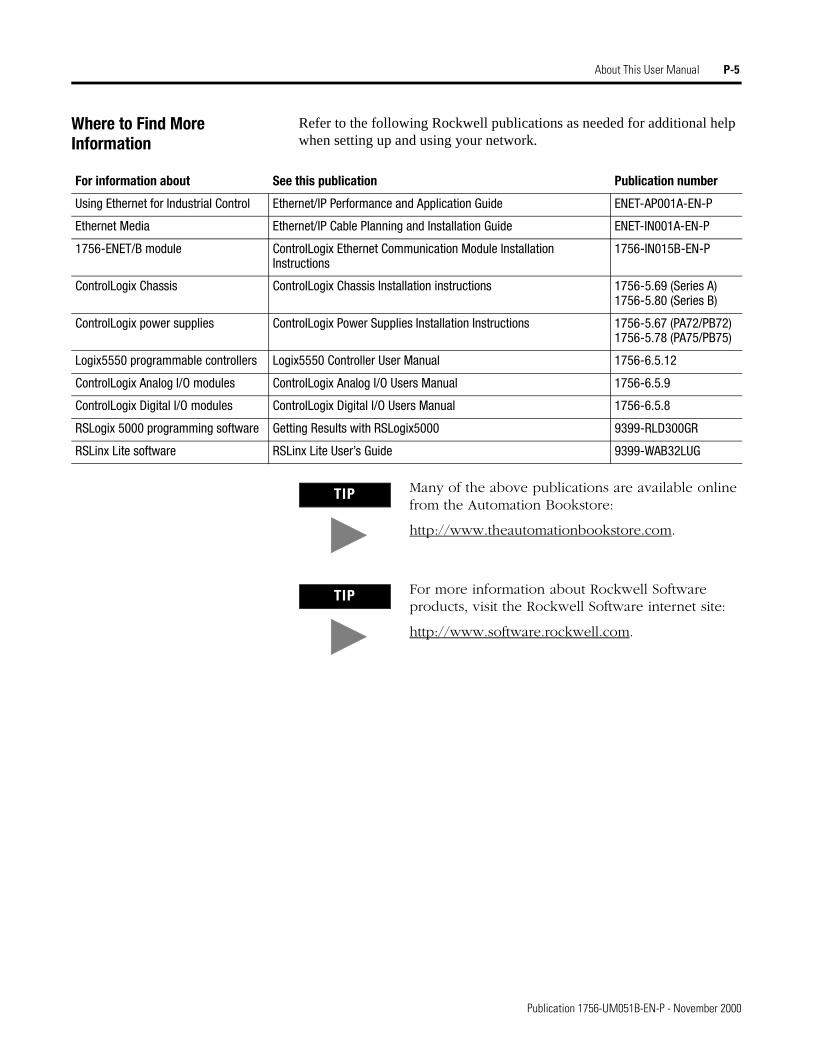
Where to Find More Information
Refer to the following Rockwell publications as needed for additional help when setting up and using your network.
For information about See this publication Publication number
Using Ethernet for Industrial Control Ethernet/IP Performance and Application Guide ENET-AP001A-EN-P
Ethernet Media Ethernet/IP Cable Planning and Installation Guide ENET-IN001A-EN-P
1756-ENET/B module ControlLogix Ethernet Communication Module Installation Instructions
1756-IN015B-EN-P
ControlLogix Chassis ControlLogix Chassis Installation instructions 1756-5.69 (Series A)1756-5.80 (Series B)
ControlLogix power supplies ControlLogix Power Supplies Installation Instructions 1756-5.67 (PA72/PB72)1756-5.78 (PA75/PB75)
Logix5550 programmable controllers Logix5550 Controller User Manual 1756-6.5.12
ControlLogix Analog I/O modules ControlLogix Analog I/O Users Manual 1756-6.5.9
ControlLogix Digital I/O modules ControlLogix Digital I/O Users Manual 1756-6.5.8
RSLogix 5000 programming software Getting Results with RSLogix5000 9399-RLD300GR
RSLinx Lite software RSLinx Lite User’s Guide 9399-WAB32LUG
TIP Many of the above publications are available online from the Automation Bookstore:
http://www.theautomationbookstore.com.
TIP For more information about Rockwell Software products, visit the Rockwell Software internet site:
http://www.software.rockwell.com.
Publication 1756-UM051B-EN-P - November 2000
P-6 About This User Manual
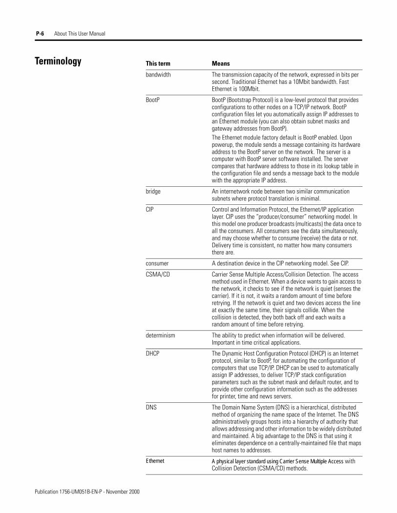
Terminology This term Means
bandwidth The transmission capacity of the network, expressed in bits per second. Traditional Ethernet has a 10Mbit bandwidth. Fast Ethernet is 100Mbit.
BootP BootP (Bootstrap Protocol) is a low-level protocol that provides configurations to other nodes on a TCP/IP network. BootP configuration files let you automatically assign IP addresses to an Ethernet module (you can also obtain subnet masks and gateway addresses from BootP).The Ethernet module factory default is BootP enabled. Upon powerup, the module sends a message containing its hardware address to the BootP server on the network. The server is a computer with BootP server software installed. The server compares that hardware address to those in its lookup table in the configuration file and sends a message back to the module with the appropriate IP address.
bridge An internetwork node between two similar communication subnets where protocol translation is minimal.
CIP Control and Information Protocol, the Ethernet/IP application layer. CIP uses the “producer/consumer” networking model. In this model one producer broadcasts (multicasts) the data once to all the consumers. All consumers see the data simultaneously, and may choose whether to consume (receive) the data or not. Delivery time is consistent, no matter how many consumers there are.
consumer A destination device in the CIP networking model. See CIP.
CSMA/CD Carrier Sense Multiple Access/Collision Detection. The access method used in Ethernet. When a device wants to gain access to the network, it checks to see if the network is quiet (senses the carrier). If it is not, it waits a random amount of time before retrying. If the network is quiet and two devices access the line at exactly the same time, their signals collide. When the collision is detected, they both back off and each waits a random amount of time before retrying.
determinism The ability to predict when information will be delivered. Important in time critical applications.
DHCP The Dynamic Host Configuration Protocol (DHCP) is an Internet protocol, similar to BootP, for automating the configuration of computers that use TCP/IP. DHCP can be used to automatically assign IP addresses, to deliver TCP/IP stack configuration parameters such as the subnet mask and default router, and to provide other configuration information such as the addresses for printer, time and news servers.
DNS The Domain Name System (DNS) is a hierarchical, distributed method of organizing the name space of the Internet. The DNS administratively groups hosts into a hierarchy of authority that allows addressing and other information to be widely distributed and maintained. A big advantage to the DNS is that using it eliminates dependence on a centrally-maintained file that maps host names to addresses.
Ethernet A physical layer standard using Carrier Sense Multiple Access with Collision Detection (CSMA/CD) methods.
Publication 1756-UM051B-EN-P - November 2000
About This User Manual P-7
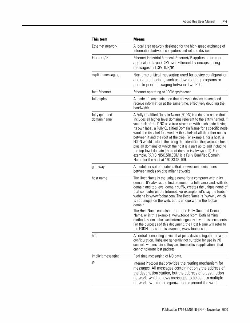
Ethernet network A local area network designed for the high-speed exchange of information between computers and related devices.
Ethernet/IP Ethernet Industrial Protocol. Ethernet/IP applies a common application layer (CIP) over Ethernet by encapsulating messages in TCP/UDP/IP.
explicit messaging Non-time critical messaging used for device configuration and data collection, such as downloading programs or peer-to-peer messaging between two PLCs.
fast Ethernet Ethernet operating at 100Mbps/second.
full duplex A mode of communication that allows a device to send and receive information at the same time, effectively doubling the bandwidth.
fully qualifieddomain name
A Fully Qualified Domain Name (FQDN) is a domain name that includes all higher level domains relevant to the entity named. If you think of the DNS as a tree-structure with each node having its own label, a Fully Qualified Domain Name for a specific node would be its label followed by the labels of all the other nodes between it and the root of the tree. For example, for a host, a FQDN would include the string that identifies the particular host, plus all domains of which the host is a part up to and including the top-level domain (the root domain is always null). For example, PARIS.NISC.SRI.COM is a Fully Qualified Domain Name for the host at 192.33.33.109.
gateway A module or set of modules that allows communications between nodes on dissimilar networks.
host name The Host Name is the unique name for a computer within its domain. It’s always the first element of a full name, and, with its domain and top-level domain suffix, creates the unique name of that computer on the Internet. For example, let’s say the foobar website is www.foobar.com. The Host Name is “www”, which is not unique on the web, but is unique within the foobar domain.The Host Name can also refer to the Fully Qualified Domain Name, or in this example, www.foobar.com. Both naming methods seem to be used interchangeably in various documents. For the purposes of this document, the Host Name will refer to the FQDN, or as in this example, www.foobar.com.
hub A central connecting device that joins devices together in a star configuration. Hubs are generally not suitable for use in I/O control systems, since they are time critical applications that cannot tolerate lost packets.
implicit messaging Real time messaging of I/O data.
IP Internet Protocol that provides the routing mechanism for messages. All messages contain not only the address of the destination station, but the address of a destination network, which allows messages to be sent to multiple networks within an organization or around the world.
This term Means
Publication 1756-UM051B-EN-P - November 2000
P-8 About This User Manual
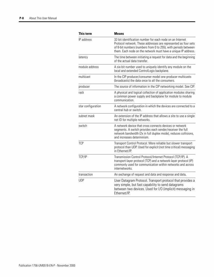
IP address 32-bit identification number for each node on an Internet Protocol network. These addresses are represented as four sets of 8-bit numbers (numbers from 0 to 255), with periods between them. Each node on the network must have a unique IP address.
latency The time between initiating a request for data and the beginning of the actual data transfer.
module address A six-bit number used to uniquely identify any module on the local and extended ControlLogix backplane.
multicast In the CIP producer/consumer model one producer multicasts (broadcasts) the data once to all the consumers.
producer The source of information in the CIP networking model. See CIP.
rack A physical and logical collection of application modules sharing a common power supply and backplane for module to module communication.
star configuration A network configuration in which the devices are connected to a central hub or switch.
subnet mask An extension of the IP address that allows a site to use a single net ID for multiple networks.
switch A network device that cross connects devices or network segments. A switch provides each sender/receiver the full network bandwidth (2x in full duplex mode), reduces collisions, and increases determinism.
TCP Transport Control Protocol. More reliable but slower transport protocol than UDP. Used for explicit (not time critical) messaging in Ethernet/IP.
TCP/IP Transmission Control Protocol/Internet Protocol (TCP/IP). A transport-layer protocol (TCP) and a network-layer protocol (IP) commonly used for communication within networks and across internetworks.
transaction An exchange of request and data and response and data.
UDP User Datagram Protocol. Transport protocol that provides a very simple, but fast capability to send datagrams between two devices. Used for I/O (implicit) messaging in Ethernet/IP.
This term Means
Publication 1756-UM051B-EN-P - November 2000
Table of Contents
Chapter 1About the 1756-ENET/B Module What This Chapter Contains . . . . . . . . . . . . . . . . . . . . . . . . . . 1-1
Module Features. . . . . . . . . . . . . . . . . . . . . . . . . . . . . . . . . . . 1-1Hardware/Software Compatibility . . . . . . . . . . . . . . . . . . . . . . 1-2What the Module Does. . . . . . . . . . . . . . . . . . . . . . . . . . . . . . 1-2Support of Rack Optimized and Direct Connections. . . . . . . . . 1-2
Mixing Rack Optimized and Direct Connections. . . . . . . . . 1-3Use of the Control and Information Protocol (CIP) . . . . . . . . . 1-4Understanding the Producer/Consumer Model. . . . . . . . . . . . . 1-4Specifying the Requested Packet Interval (RPI) . . . . . . . . . . . . 1-5What’s Next? . . . . . . . . . . . . . . . . . . . . . . . . . . . . . . . . . . . . . 1-5
Chapter 2Installing the Ethernet Module What This Chapter Contains . . . . . . . . . . . . . . . . . . . . . . . . . . 2-1
Identifying Module Features . . . . . . . . . . . . . . . . . . . . . . . . . . 2-1Insertion and Removal Under Power. . . . . . . . . . . . . . . . . . . . 2-2Installing the Ethernet Module . . . . . . . . . . . . . . . . . . . . . . . . 2-2
Preparing the Chassis for Module Installation . . . . . . . . . . . 2-2Determining Module Slot Location. . . . . . . . . . . . . . . . . . . 2-3Inserting the Module in the Chassis . . . . . . . . . . . . . . . . . . 2-4Removing or Replacing the Module (when applicable) . . . . 2-5Wiring the Ethernet Connector . . . . . . . . . . . . . . . . . . . . . 2-6Connecting the Module to the Ethernet Network . . . . . . . . 2-6Applying Chassis Power . . . . . . . . . . . . . . . . . . . . . . . . . . 2-7Checking Power Supply and Module Status . . . . . . . . . . . . 2-8
What’s Next? . . . . . . . . . . . . . . . . . . . . . . . . . . . . . . . . . . . . . 2-8
Chapter 3Before You Configure Your Module
What This Chapter Contains . . . . . . . . . . . . . . . . . . . . . . . . . . 3-1Ethernet Protocols . . . . . . . . . . . . . . . . . . . . . . . . . . . . . . . . . 3-1
Transmission Control Protocol/Internet Protocol (TCP/IP) . 3-1User Datagram Protocol (UDP) . . . . . . . . . . . . . . . . . . . . . 3-2Ethernet/IP . . . . . . . . . . . . . . . . . . . . . . . . . . . . . . . . . . . . 3-2Simple Network Management Protocol (SNMP) . . . . . . . . . 3-2
Configuring the Module . . . . . . . . . . . . . . . . . . . . . . . . . . . . . 3-3IP Address . . . . . . . . . . . . . . . . . . . . . . . . . . . . . . . . . . . . 3-3Gateways . . . . . . . . . . . . . . . . . . . . . . . . . . . . . . . . . . . . . 3-4Subnet Masks . . . . . . . . . . . . . . . . . . . . . . . . . . . . . . . . . . 3-5
For More Information . . . . . . . . . . . . . . . . . . . . . . . . . . . . . . . 3-6What’s Next? . . . . . . . . . . . . . . . . . . . . . . . . . . . . . . . . . . . . . 3-6
i Publication 1756-UM051B-EN-P - November 2000
Table of Contents ii
Chapter 4Configuring the Ethernet Module What This Chapter Contains . . . . . . . . . . . . . . . . . . . . . . . . . . 4-1
Using the Rockwell BootP Utility . . . . . . . . . . . . . . . . . . . . . . 4-1Using RSLinx Software . . . . . . . . . . . . . . . . . . . . . . . . . . . . . . 4-2Using a BootP Server . . . . . . . . . . . . . . . . . . . . . . . . . . . . . . . 4-5Using DHCP Software to Configure Your Module . . . . . . . . . . 4-7What’s Next? . . . . . . . . . . . . . . . . . . . . . . . . . . . . . . . . . . . . . 4-7
Chapter 5Rack Optimized I/O About the Example Application . . . . . . . . . . . . . . . . . . . . . . . 5-1
Set Up the Hardware . . . . . . . . . . . . . . . . . . . . . . . . . . . . . . . 5-2Create the Example Application . . . . . . . . . . . . . . . . . . . . . . . 5-3
Add the Local Ethernet Module to the I/O Configuration . . 5-4Add the Remote Ethernet Module to the I/O Configuration. 5-6Add the Remote I/O Modules to the I/O Configuration . . . 5-8
Add the Remote Digital Input Module . . . . . . . . . . . . . 5-8Add the Remote Digital Output Module . . . . . . . . . . . 5-10
Edit the Controller Tags . . . . . . . . . . . . . . . . . . . . . . . . . 5-12Create the Ladder Program . . . . . . . . . . . . . . . . . . . . . . . 5-14Download the Program to the Controller . . . . . . . . . . . . . 5-15
Test the Example Application . . . . . . . . . . . . . . . . . . . . . . . . 5-16What’s Next? . . . . . . . . . . . . . . . . . . . . . . . . . . . . . . . . . . . . 5-17
Chapter 6Analog I/O with Direct Connection About the Example Application . . . . . . . . . . . . . . . . . . . . . . . 6-1
Set Up the Hardware . . . . . . . . . . . . . . . . . . . . . . . . . . . . . . . 6-2Create the Example Application . . . . . . . . . . . . . . . . . . . . . . . 6-3
Add the Remote Analog I/O Moduleto the I/O Configuration . . . . . . . . . . . . . . . . . . . . . . . . . . 6-4Edit the Controller Tags . . . . . . . . . . . . . . . . . . . . . . . . . . 6-8Modify the Ladder Program . . . . . . . . . . . . . . . . . . . . . . . 6-10Download the Program. . . . . . . . . . . . . . . . . . . . . . . . . . 6-11
Test the Example Application . . . . . . . . . . . . . . . . . . . . . . . . 6-12What’s Next? . . . . . . . . . . . . . . . . . . . . . . . . . . . . . . . . . . . . 6-12
Chapter 7Produced and Consumed Tags About the Example Application . . . . . . . . . . . . . . . . . . . . . . . 7-1
Set Up the Hardware . . . . . . . . . . . . . . . . . . . . . . . . . . . . . . . 7-2Create the Producer Application . . . . . . . . . . . . . . . . . . . . . . . 7-3
Create the Producer Tags . . . . . . . . . . . . . . . . . . . . . . . . . 7-4Create the Producer Ladder Program . . . . . . . . . . . . . . . . . 7-6Download the Producer Application . . . . . . . . . . . . . . . . . 7-7
Create the Consumer Application . . . . . . . . . . . . . . . . . . . . . . 7-8Create the Consumer Controller. . . . . . . . . . . . . . . . . . . . . 7-8Add the Producer to the Consumer’s I/O Configuration . . . 7-9
Add the Local ENET/B Moduleto the I/O Configuration . . . . . . . . . . . . . . . . . . . . . . . 7-9
Publication 1756-UM051B-EN-P - November 2000
Table of Contents iii
Chapter 7 (continued)Add the Remote ENET/B Moduleto the I/O Configuration . . . . . . . . . . . . . . . . . . . . . . 7-11Add the Remote (Producer) Controllerto the I/O Configuration . . . . . . . . . . . . . . . . . . . . . . 7-13
Create the Consumer Tags. . . . . . . . . . . . . . . . . . . . . . . . 7-15Download the Configuration to the Consumer . . . . . . . . . 7-18
Test the Messaging . . . . . . . . . . . . . . . . . . . . . . . . . . . . . . . . 7-19What’s Next? . . . . . . . . . . . . . . . . . . . . . . . . . . . . . . . . . . . . 7-19
Appendix ALED Status Indicators Interpreting the Status Indicators. . . . . . . . . . . . . . . . . . . . . . . A-1
Appendix B1756-ENET/B Module Web Pages Web Page Diagnostics . . . . . . . . . . . . . . . . . . . . . . . . . . . . . . B-1
Module Information . . . . . . . . . . . . . . . . . . . . . . . . . . . . . B-2TCP/IP Configuration . . . . . . . . . . . . . . . . . . . . . . . . . . . . B-2Diagnostic Information . . . . . . . . . . . . . . . . . . . . . . . . . . . B-3
ENET/IP Statistics . . . . . . . . . . . . . . . . . . . . . . . . . . . . B-3ENET/IP (CIP) STATISTICS . . . . . . . . . . . . . . . . . . . . . B-4
Chassis Who. . . . . . . . . . . . . . . . . . . . . . . . . . . . . . . . . . . B-5
Appendix CConfiguring the RSLinx Ethernet Communication Driver
What This Appendix Contains. . . . . . . . . . . . . . . . . . . . . . . . . C-1Installing the RSLinx Software . . . . . . . . . . . . . . . . . . . . . . . . . C-1Configuring the AB_ETH Driver . . . . . . . . . . . . . . . . . . . . . . . C-2
Appendix D1756-ENET/B Support of ControlLogix Gateway Communication
Using the 1756-ENET/B Module in a ControlLogix Gateway. . D-1
Appendix EExample Network Configurations What This Appendix Contains. . . . . . . . . . . . . . . . . . . . . . . . . E-1
Small System Example . . . . . . . . . . . . . . . . . . . . . . . . . . . . . . E-2Expanded System with FLEX I/O . . . . . . . . . . . . . . . . . . . . . . E-3Larger Control Networks. . . . . . . . . . . . . . . . . . . . . . . . . . . . . E-4
Appendix FElectronic Keying Specifying Electronic Keying. . . . . . . . . . . . . . . . . . . . . . . . . . F-1
Index
Publication 1756-UM051B-EN-P - November 2000

Table of Contents iv
Publication 1756-UM051B-EN-P - November 2000
Chapter 1
About the 1756-ENET/B Module
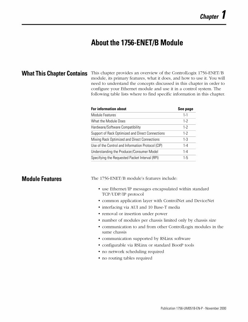
What This Chapter Contains This chapter provides an overview of the ControlLogix 1756-ENET/B module, its primary features, what it does, and how to use it. You will need to understand the concepts discussed in this chapter in order to configure your Ethernet module and use it in a control system. The following table lists where to find specific information in this chapter.
.
Module Features The 1756-ENET/B module’s features include:
• use Ethernet/IP messages encapsulated within standard TCP/UDP/IP protocol
• common application layer with ControlNet and DeviceNet
• interfacing via AUI and 10 Base-T media
• removal or insertion under power
• number of modules per chassis limited only by chassis size
• communication to and from other ControlLogix modules in the same chassis
• communication supported by RSLinx software
• configurable via RSLinx or standard BootP tools
• no network scheduling required
• no routing tables required
For information about See pageModule Features 1-1
What the Module Does 1-2
Hardware/Software Compatibility 1-2
Support of Rack Optimized and Direct Connections 1-2
Mixing Rack Optimized and Direct Connections 1-3
Use of the Control and Information Protocol (CIP) 1-4
Understanding the Producer/Consumer Model 1-4
Specifying the Requested Packet Interval (RPI) 1-5
1 Publication 1756-UM051B-EN-P - November 2000
1-2 About the 1756-ENET/B Module
Hardware/Software Compatibility
The 1756-ENET/B module is compatible with the following firmware versions and software releases. Contact Rockwell Automation if you need software or firmware upgrades to use this equipment.:
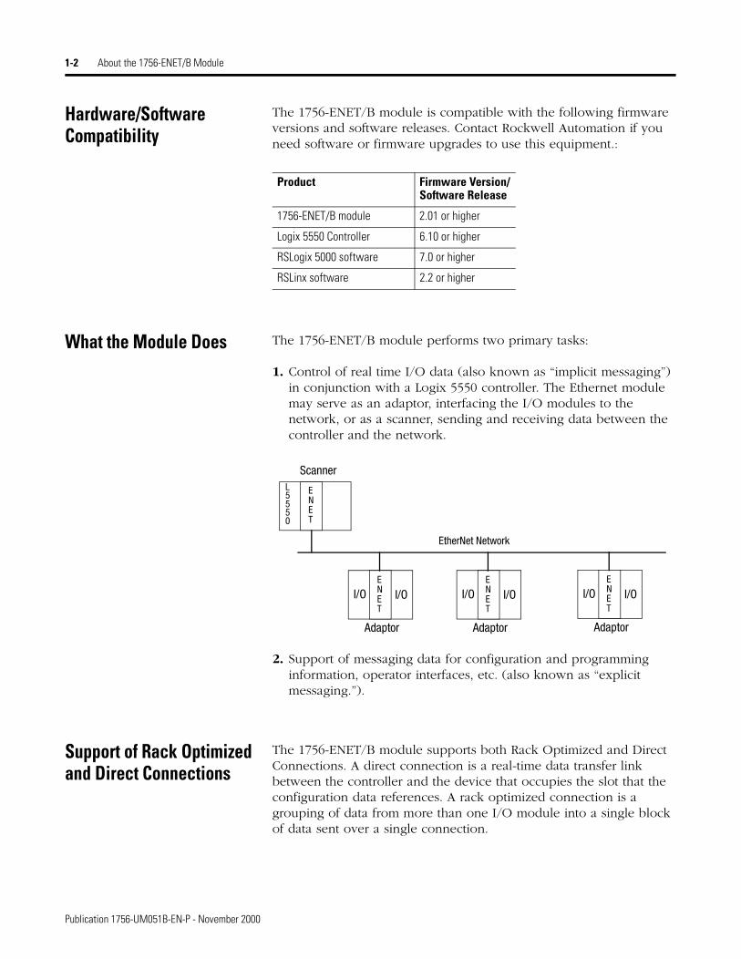
What the Module Does The 1756-ENET/B module performs two primary tasks:
1. Control of real time I/O data (also known as “implicit messaging”) in conjunction with a Logix 5550 controller. The Ethernet module may serve as an adaptor, interfacing the I/O modules to the network, or as a scanner, sending and receiving data between the controller and the network.
2. Support of messaging data for configuration and programming information, operator interfaces, etc. (also known as “explicit messaging.”).
Support of Rack Optimized and Direct Connections
The 1756-ENET/B module supports both Rack Optimized and Direct Connections. A direct connection is a real-time data transfer link between the controller and the device that occupies the slot that the configuration data references. A rack optimized connection is a grouping of data from more than one I/O module into a single block of data sent over a single connection.
Product Firmware Version/Software Release
1756-ENET/B module 2.01 or higher
Logix 5550 Controller 6.10 or higher
RSLogix 5000 software 7.0 or higher
RSLinx software 2.2 or higher
I/O I/O
L5550
ENET
Scanner
Adaptor
EtherNet Network
ENET
I/O I/OENET
Adaptor
I/O I/OENET
Adaptor
Publication 1756-UM051B-EN-P - November 2000
About the 1756-ENET/B Module 1-3
Rack optimized connections reduce the total number of connections needed to transfer data when using many I/O modules in a system. The following example illustrates the benefit of rack optimized connections.
Assume you have set up a system that contains 10 discrete I/O modules in a remote ControlLogix chassis. If you use direct connections to transfer data to each of the these I/O modules, you need 10 connections to transfer all of the data, one to each of the ten I/O modules. If you use a rack-optimized connection to transfer the data, you only need a single connection – the connection to the Ethernet module.
See the Ethernet Performance and Application Guide, publication number ENET-AP001A-EN-P, for more information on connections.
Mixing Rack Optimized and Direct Connections
You can mix communication formats for different I/O modules in the same chassis. I/O modules set up to use Rack Optimization will communicate at the rate of the RPI (requested packet interval) configured for the 1756-ENET/B module. I/O modules configured for direct communication will communicate at their set RPI and ignore the Ethernet module’s RPI.
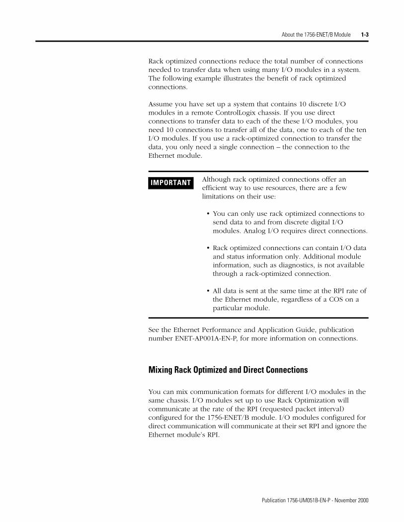
IMPORTANT Although rack optimized connections offer an efficient way to use resources, there are a few limitations on their use:
• You can only use rack optimized connections to send data to and from discrete digital I/O modules. Analog I/O requires direct connections.
• Rack optimized connections can contain I/O data and status information only. Additional module information, such as diagnostics, is not available through a rack-optimized connection.
• All data is sent at the same time at the RPI rate of the Ethernet module, regardless of a COS on a particular module.
Publication 1756-UM051B-EN-P - November 2000
1-4 About the 1756-ENET/B Module
Use of the Control and Information Protocol (CIP)
The Ethernet module uses the Control and Information Protocol (CIP). CIP is the application layer protocol specified for Ethernet/IP, the Ethernet Industrial Protocol, as well as for ControlNet and DeviceNet. It is a message-based protocol that implements a relative path to send a message from the “producing” device in a system to the “consuming” devices. The producing device contains the path information that steers the message along the proper route to reach its consumers. Since the producing device holds this information, other devices along the path simply pass this information; they do not need to store it. This has two significant benefits:
• You do not need to configure routing tables in the bridging module, which greatly simplifies maintenance and module replacement.
• You maintain full control over the route taken by each message, which enables you to select alternative paths for the same end device.
Understanding the Producer/Consumer Model
CIP uses the “producer/consumer” networking model, replacing the old source/destination (master/slave) model. The producer/consumer model reduces network traffic and increases speed of transmission. In traditional I/O systems, controllers poll input modules to obtain their input status. In the CIP system digital input modules are not polled by a controller. Instead, they produce (“multicast”) their data either upon a change of state (COS) or periodically. The frequency of update depends upon the options chosen during configuration and where on the network the input module resides. The input module, therefore, is a producer of input data and the controller is a consumer of the data.
The controller can also produce data for other controllers to consume. The produced and consumed data is accessible by multiple controllers over the ControlLogix backplane and over the Ethernet network. This data exchange conforms to the producer/consumer model.
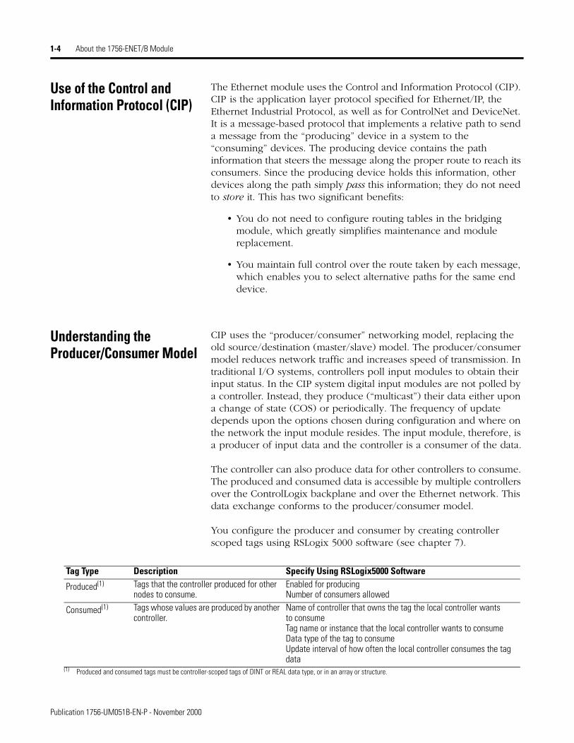
You configure the producer and consumer by creating controller scoped tags using RSLogix 5000 software (see chapter 7).
Tag Type Description Specify Using RSLogix5000 Software
Produced(1) Tags that the controller produced for other nodes to consume.
Enabled for producingNumber of consumers allowed
Consumed(1) Tags whose values are produced by another controller.
Name of controller that owns the tag the local controller wants to consumeTag name or instance that the local controller wants to consumeData type of the tag to consumeUpdate interval of how often the local controller consumes the tag data
(1) Produced and consumed tags must be controller-scoped tags of DINT or REAL data type, or in an array or structure.
Publication 1756-UM051B-EN-P - November 2000
About the 1756-ENET/B Module 1-5
Specifying the Requested Packet Interval (RPI)
The RPI is the update rate specified for a particular piece of data on the network. The RPI can be specified for an entire rack (using a rack optimized connection) or for a particular module (using direct connection). When you add a module to the I/O configuration of a controller, you must enter the RPI as a parameter. ‘This value specifies how often to produce the data for that module. For example, if you specify an RPI of 50ms, it means that every 50ms the I/O module should send its data to the controller or that the controller should send its data to the I/O module.
RPIs are only used for modules that produce data. For example a local 1756-ENET/B module (i.e., an ENET/B module in the same chassis as the controller) does not require an RPI because it is not a data-producing member of the system; it is used only as a bridge to remote racks.
What’s Next? The following chapter describes how to install the Ethernet module and connect it to the network.
Publication 1756-UM051B-EN-P - November 2000

1-6 About the 1756-ENET/B Module
Publication 1756-UM051B-EN-P - November 2000
Chapter 2
Installing the Ethernet Module
What This Chapter Contains This chapter describes how to install the module in the ControlLogix chassis and connect it to the network. The following table describes what this chapter contains and where to find specific information.
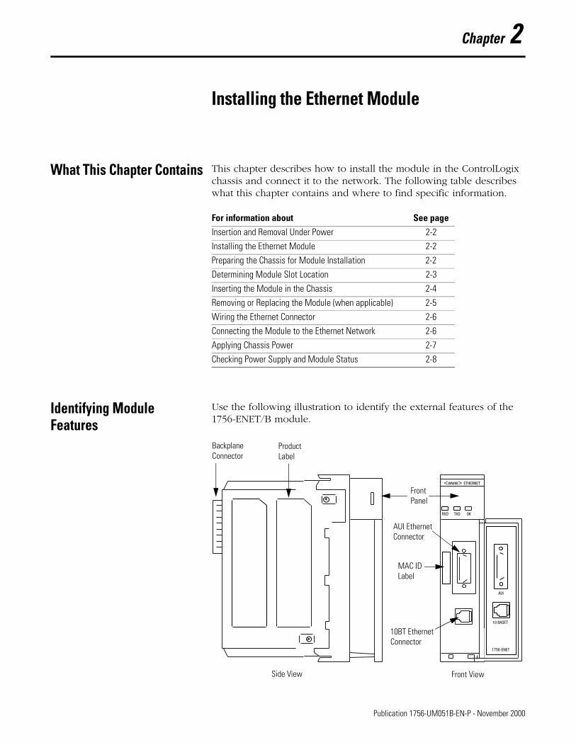
Identifying Module Features
Use the following illustration to identify the external features of the 1756-ENET/B module.
For information about See pageInsertion and Removal Under Power 2-2
Installing the Ethernet Module 2-2
Preparing the Chassis for Module Installation 2-2
Determining Module Slot Location 2-3
Inserting the Module in the Chassis 2-4
Removing or Replacing the Module (when applicable) 2-5
Wiring the Ethernet Connector 2-6
Connecting the Module to the Ethernet Network 2-6
Applying Chassis Power 2-7
Checking Power Supply and Module Status 2-8
<www> ETHERNET
OKTXDRXD
AUI
10 BASET
1756-ENET
Backplane Connector
Product Label
AUI EthernetConnector
10BT EthernetConnector
Side View Front View
FrontPanel
MAC IDLabel
1 Publication 1756-UM051B-EN-P - November 2000
2-2 Installing the Ethernet Module
Insertion and Removal Under Power
The Ethernet module is designed to be installed or removed while chassis power is applied. However, please observe the following precautions.
Installing the Ethernet Module
Use the following procedure to install the Ethernet module.
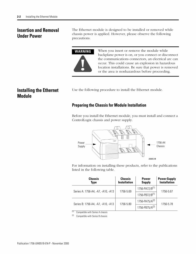
Preparing the Chassis for Module Installation
Before you install the Ethernet module, you must install and connect a ControlLogix chassis and power supply.
For information on installing these products, refer to the publications listed in the following table.
WARNING
!When you insert or remove the module while backplane power is on, or you connect or disconnect the communications connectors, an electrical arc can occur. This could cause an explosion in hazardous location installations. Be sure that power is removed or the area is nonhazardous before proceeding.
ChassisType
Chassis Installation
PowerSupply
Power Supply Installation
Series A: 1756-A4, -A7, -A10, -A13 1756-5.691756-PA72/B(1)
(1) Compatible with Series A chassis
1756-5.671756-PB72/B(1)
Series B: 1756-A4, -A7, -A10, -A13 1756-5.801756-PA75/A(2)
(2) Compatible with Series B chassis
1756-5.781756-PB75/A(2)
20805-M
1756-A4 Chassis
Power Supply
Publication 1756-UM051B-EN-P - November 2000
Installing the Ethernet Module 2-3
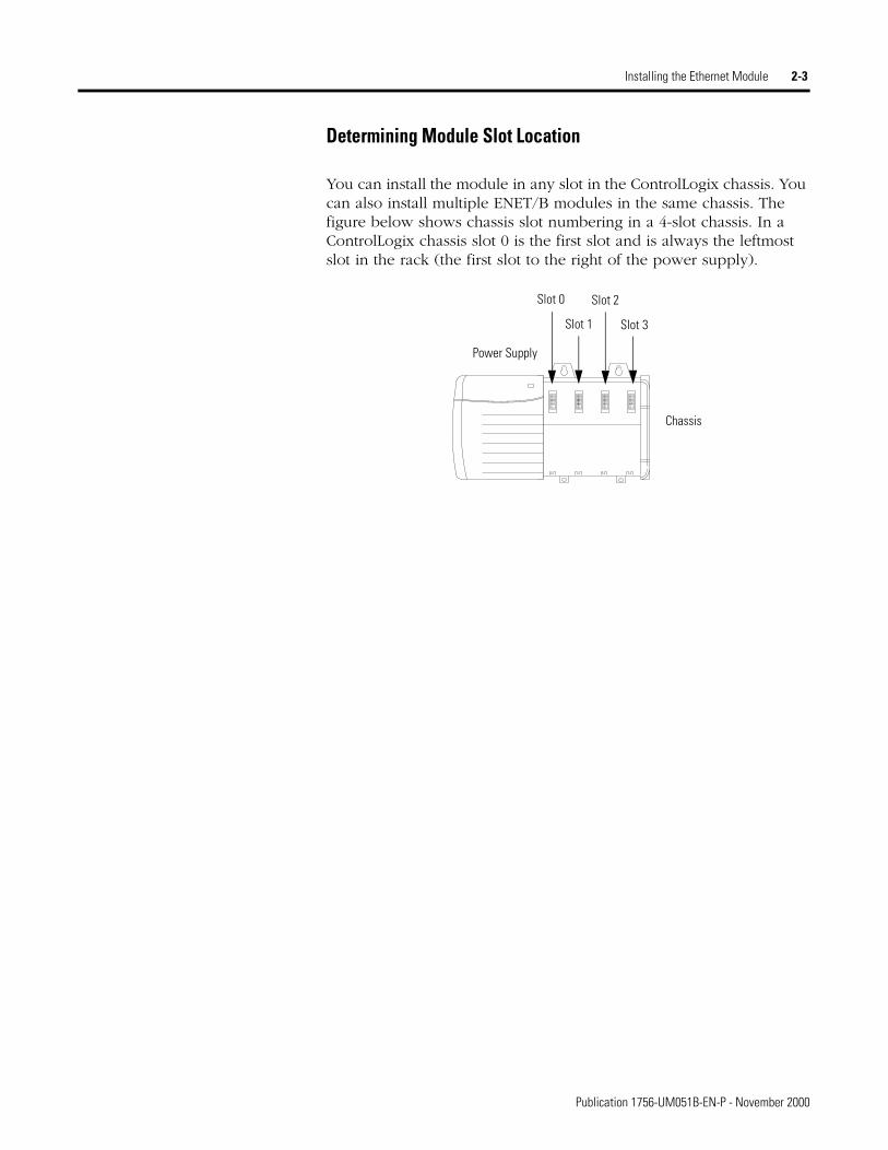
Determining Module Slot Location
You can install the module in any slot in the ControlLogix chassis. You can also install multiple ENET/B modules in the same chassis. The figure below shows chassis slot numbering in a 4-slot chassis. In a ControlLogix chassis slot 0 is the first slot and is always the leftmost slot in the rack (the first slot to the right of the power supply).
Power Supply
Slot 0
Slot 1
Slot 2
Slot 3
Chassis
Publication 1756-UM051B-EN-P - November 2000
2-4 Installing the Ethernet Module
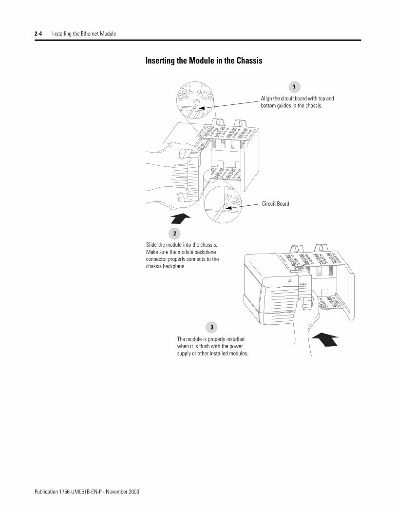
Inserting the Module in the Chassis
Align the circuit board with top and bottom guides in the chassis.
1
Slide the module into the chassis. Make sure the module backplane connector properly connects to the chassis backplane.
2
The module is properly installed when it is flush with the power supply or other installed modules.
Circuit Board
3
Publication 1756-UM051B-EN-P - November 2000
Installing the Ethernet Module 2-5
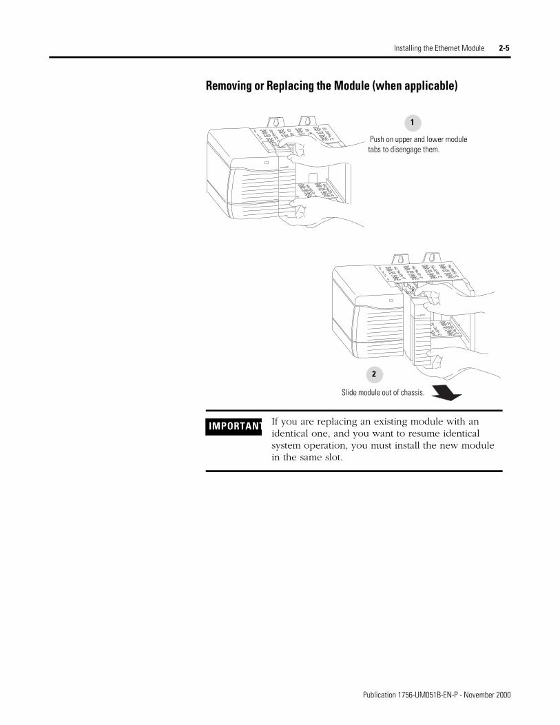
Removing or Replacing the Module (when applicable)
IMPORTANT If you are replacing an existing module with an identical one, and you want to resume identical system operation, you must install the new module in the same slot.
Push on upper and lower module tabs to disengage them.
1
Slide module out of chassis.
2
Publication 1756-UM051B-EN-P - November 2000
2-6 Installing the Ethernet Module
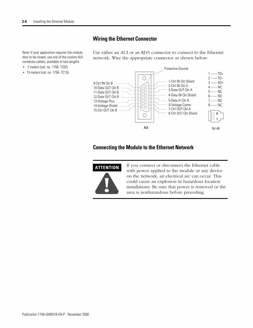
Wiring the Ethernet Connector
Use either an AUI or an RJ45 connector to connect to the Ethernet network. Wire the appropriate connector as shown below:
Connecting the Module to the Ethernet Network
ATTENTION
!If you connect or disconnect the Ethernet cable with power applied to the module or any device on the network, an electrical arc can occur. This could cause an explosion in hazardous location installations. Be sure that power is removed or the area is nonhazardous before proceding.
Note: If your application requires the module door to be closed, use one of the custom AUI connector cables, available in two lengths:• 2 meters (cat. no. 1756- TC02)• 15 meters (cat. no. 1756- TC15)
AUI RJ 45
8
1
1-Ctrl IN Ckt Shield2-Ctrl IN Ckt A3-Data OUT Ckt A4-Data IN Ckt Shield5-Data In Ckt A6-Voltage Comm7-Ctrl OUT Ckt A8-Ctrl OUT Ckt Shield
9-Ctrl IN Ckt B10-Data OUT Ckt B11-Data OUT Ckt B12-Data OUT Ckt B13-Voltage Plus14-Voltage Shield15-Ctrl OUT Ckt B
Protective Ground1 ------ TD+2 ------ TD-3 ------ RD+4 ------ NC5 ------ NC6 ------ RD-7 ------ NC8 ------ NC
Publication 1756-UM051B-EN-P - November 2000
Installing the Ethernet Module 2-7
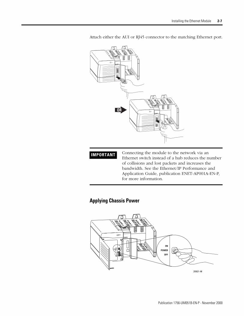
Attach either the AUI or RJ45 connector to the matching Ethernet port.
Applying Chassis Power
IMPORTANT Connecting the module to the network via an Ethernet switch instead of a hub reduces the number of collisions and lost packets and increases the bandwidth. See the Ethernet/IP Performance and Application Guide, publication ENET-AP001A-EN-P, for more information.
POWER
POWER
OR
20921-M
ON
POWER
OFF
ONPOWER
OFF
Publication 1756-UM051B-EN-P - November 2000
2-8 Installing the Ethernet Module
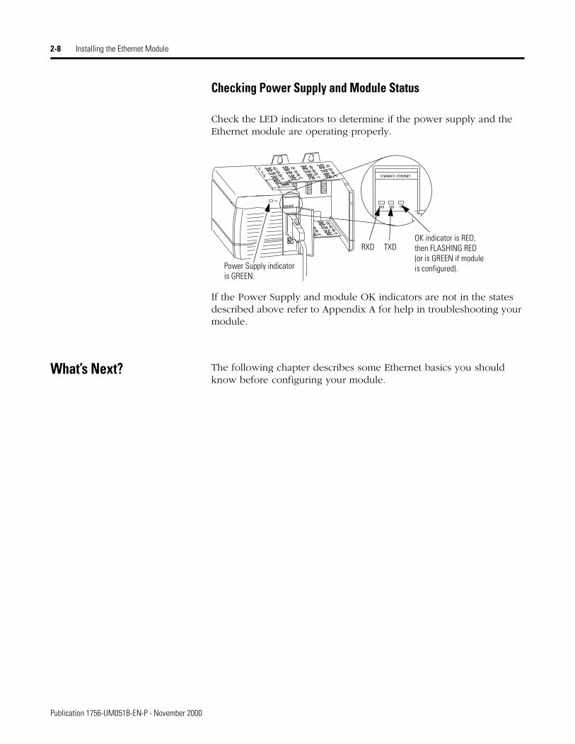
Checking Power Supply and Module Status
Check the LED indicators to determine if the power supply and the Ethernet module are operating properly.
If the Power Supply and module OK indicators are not in the states described above refer to Appendix A for help in troubleshooting your module.
What’s Next? The following chapter describes some Ethernet basics you should know before configuring your module.
OKTXDRXD
<www> ETHERNET
POWER
OK indicator is RED,then FLASHING RED(or is GREEN if moduleis configured).Power Supply indicator
is GREEN.
RXD TXD
Publication 1756-UM051B-EN-P - November 2000
Chapter 3
Before You Configure Your Module
What This Chapter Contains This chapter describes some of the basics you should know about Ethernet before you configure your Ethernet module. The following table describes where to find specific information in this chapter.
Ethernet Protocols On the most basic level, Ethernet is a wire or cable that connects computers and peripheral devices so that they can communicate. The actual wire used for the network is referred to as the network “medium.” Beyond the physical medium, all Ethernet networks support protocols that provide sophisticated data transfer and network management functionality.
Transmission Control Protocol/Internet Protocol (TCP/IP)
Transmission Control Protocol/Internet Protocol (TCP/IP) is a transport-layer protocol (TCP) and a network-layer protocol (IP) commonly used in business environments for communication within networks and across internetworks. The 1756-ENET/B module uses TCP/IP for “explicit” messaging, that is, messages in which time is not a critical factor, such as uploading or downloading programs.
For information about See pageEthernet Protocols 3-1
Transmission Control Protocol/Internet Protocol (TCP/IP) 3-1
User Datagram Protocol (UDP) 3-2
Simple Network Management Protocol (SNMP) 3-2
Configuration Requirements 3-3
IP Address 3-3
Gateways 3-4
Subnet Mask 3-5
For More Information 3-6
1 Publication 1756-UM051B-EN-P - November 2000
3-2 Before You Configure Your Module
User Datagram Protocol (UDP)
UDP is a much simpler transport protocol. It is connectionless and provides a very simple capability to send datagrams between two devices. UDP is used by applications that implement their own handshaking between devices and only want a minimal transport service. UDP is smaller, simpler, and faster than TCP and can operate in unicast, multicast, or broadcast mode. The 1756-ENET/B module employs UDP for real time I/O messaging.
Ethernet/IP
Ethernet/IP applies a common application layer over Ethernet by encapsulating messages in TCP/UDP/IP. This common application layer is the control and information protocol (CIP, see chapter 1), which provides interoperability and interchangeability of industrial automation and control devices on Ethernet. Ethernet/IP supports both real-time I/O (“implicit” messaging) and explicit messaging.
Refer to the Ethernet/IP Performance and Application Guide, publication number ENET-AP001A-EN-P, for more information on the Ethernet/IP protocol.
Simple Network Management Protocol (SNMP)
Simple Network Management Protocol (SNMP) is a standard for network management within TCP/IP environments. This lets client applications monitor and manage network information on host computers and gateways.
SNMP uses a distributed architecture consisting of management systems and agents. Data is passed from SNMP agents, which are hardware and/or software processes reporting activity in each network device (switch, router, bridge, etc.) to the workstation console used to oversee the network. The agents return information contained in a MIB (Management Information Base), which is a data structure that defines what is obtainable from the device and what can be controlled (turned off, on, etc.).
The ENET/B module is an agent, and its primary function is to process the operations requested by the management system. The Ethernet module supports the SNMP protocol at the MIB II level.
Publication 1756-UM051B-EN-P - November 2000
Before You Configure Your Module 3-3
Configuration Requirements
Before you can use your Ethernet module, you must configure its IP address, gateway address, and subnet mask. The module ships with the Rockwell BootP utility, which you can use to perform the configuration. You can also use RSLinx software, generic BootP software, or, within some limitations, a DHCP server. These methods are described in chapter 4.
IP Address
The IP address identifies each node on the IP network (or system of connected networks). Each TCP/IP node on a network (including the Ethernet module) must have a unique IP address.
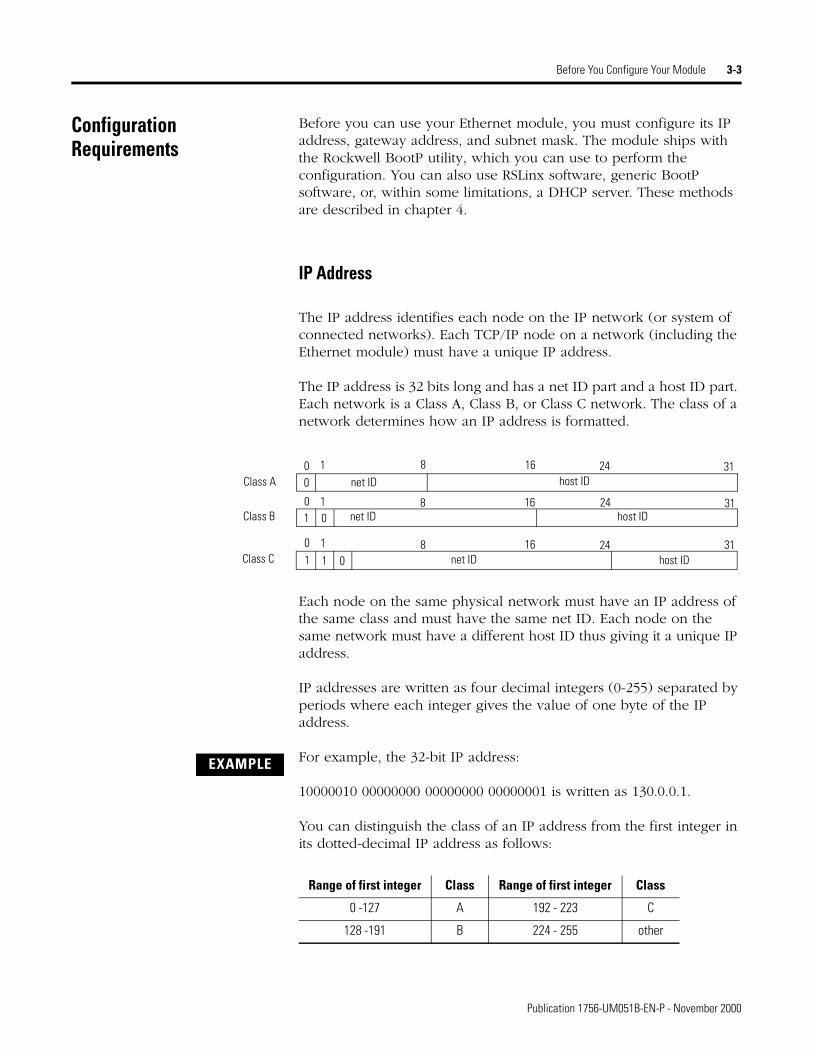
The IP address is 32 bits long and has a net ID part and a host ID part. Each network is a Class A, Class B, or Class C network. The class of a network determines how an IP address is formatted.
Each node on the same physical network must have an IP address of the same class and must have the same net ID. Each node on the same network must have a different host ID thus giving it a unique IP address.
IP addresses are written as four decimal integers (0-255) separated by periods where each integer gives the value of one byte of the IP address.
For example, the 32-bit IP address:
10000010 00000000 00000000 00000001 is written as 130.0.0.1.
You can distinguish the class of an IP address from the first integer in its dotted-decimal IP address as follows:
Class A
Class B
Class C
net ID
net ID
net ID host ID
host ID
host ID00 1
0 1
0 1
0
0
1
1 1
8
8
8
16
16
16 24
24
24
31
31
31
Range of first integer Class Range of first integer Class
0 -127 A 192 - 223 C
128 -191 B 224 - 255 other
EXAMPLE
Publication 1756-UM051B-EN-P - November 2000
3-4 Before You Configure Your Module
For more information on Internet addressing, see Comer, Douglas E; Internetworking with TCP-IP, Volume 1: Protocols and Architecture; Englewood Cliffs, N.J.: Prentice-Hall, 1990.
Gateways
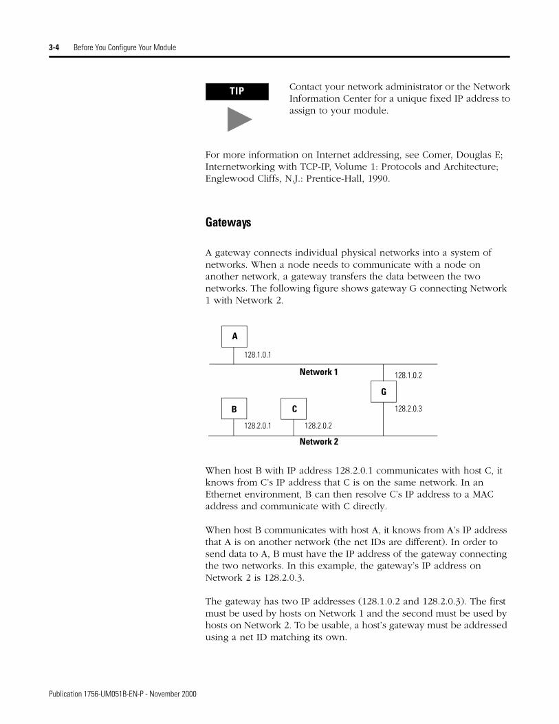
A gateway connects individual physical networks into a system of networks. When a node needs to communicate with a node on another network, a gateway transfers the data between the two networks. The following figure shows gateway G connecting Network 1 with Network 2.
When host B with IP address 128.2.0.1 communicates with host C, it knows from C’s IP address that C is on the same network. In an Ethernet environment, B can then resolve C’s IP address to a MAC address and communicate with C directly.
When host B communicates with host A, it knows from A’s IP address that A is on another network (the net IDs are different). In order to send data to A, B must have the IP address of the gateway connecting the two networks. In this example, the gateway’s IP address on Network 2 is 128.2.0.3.
The gateway has two IP addresses (128.1.0.2 and 128.2.0.3). The first must be used by hosts on Network 1 and the second must be used by hosts on Network 2. To be usable, a host’s gateway must be addressed using a net ID matching its own.
TIP Contact your network administrator or the Network Information Center for a unique fixed IP address to assign to your module.
Tip
128.1.0.1
128.2.0.1 128.2.0.2
128.2.0.3
128.1.0.2
A
B C
G
Network 1
Network 2
Publication 1756-UM051B-EN-P - November 2000
Before You Configure Your Module 3-5
Subnet Mask
Subnet addressing is an extension of the IP address scheme that allows a site to use a single net ID for multiple physical networks. Routing outside of the site continues by dividing the IP address into a net ID and a host ID via the class. Inside a site, the subnet mask is used to redivide the IP address into a custom net ID portion and host ID portion.
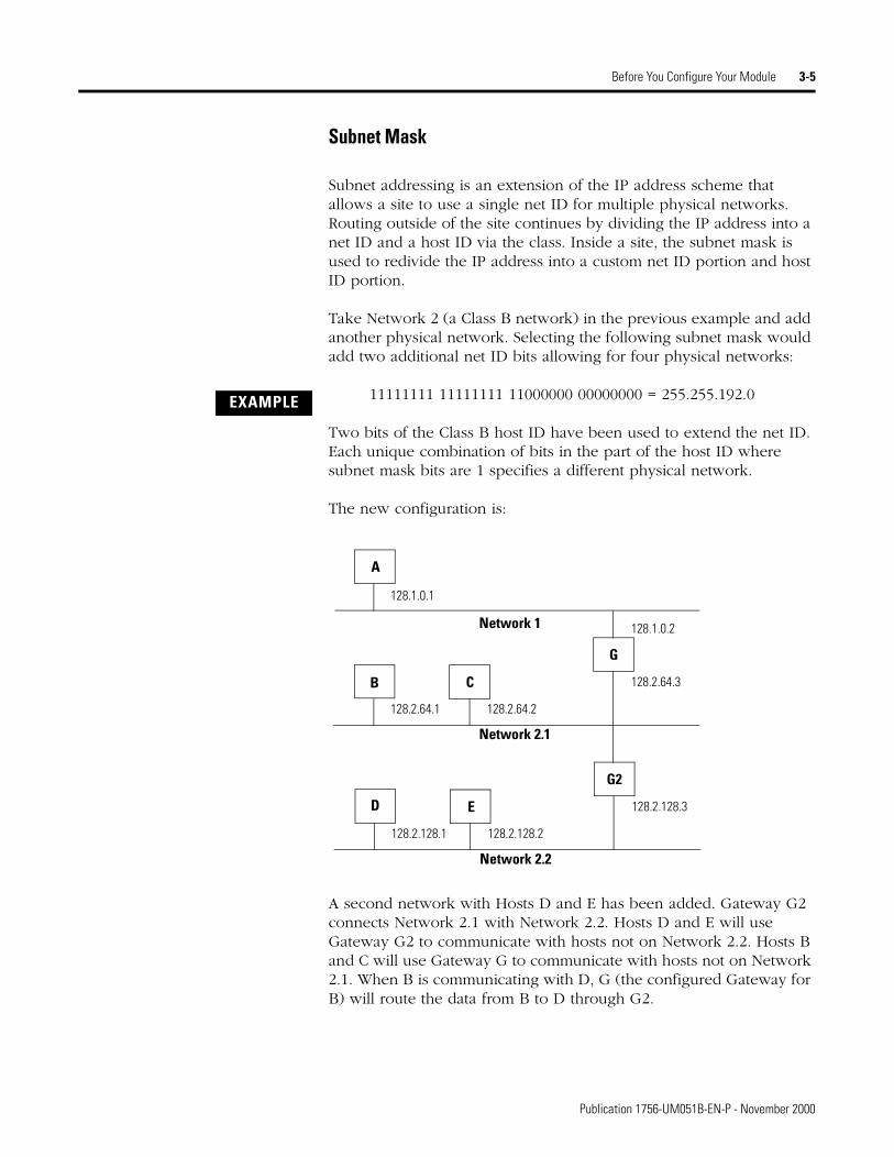
Take Network 2 (a Class B network) in the previous example and add another physical network. Selecting the following subnet mask would add two additional net ID bits allowing for four physical networks:
11111111 11111111 11000000 00000000 = 255.255.192.0
Two bits of the Class B host ID have been used to extend the net ID. Each unique combination of bits in the part of the host ID where subnet mask bits are 1 specifies a different physical network.
The new configuration is:
A second network with Hosts D and E has been added. Gateway G2 connects Network 2.1 with Network 2.2. Hosts D and E will use Gateway G2 to communicate with hosts not on Network 2.2. Hosts B and C will use Gateway G to communicate with hosts not on Network 2.1. When B is communicating with D, G (the configured Gateway for B) will route the data from B to D through G2.
EXAMPLE
128.1.0.1
128.2.64.1 128.2.64.2
128.2.64.3
128.1.0.2
A
B C
G
Network 1
Network 2.1
128.2.128.1 128.2.128.2
128.2.128.3D E
G2
Network 2.2
Publication 1756-UM051B-EN-P - November 2000
3-6 Before You Configure Your Module
For More Information For more information about Ethernet, refer to the following publications:
What’s Next? The following chapter describes how to configure your Ethernet module.
• Internetworking with TCP/IPVol. 1, 2nd ed.by Douglas E. Comer
ISBN 0-13-216987-8
• The Ethernet Management Guide – Keeping The Link
ISBN 0-07-046320-4
• An Introduction to TCP/IP ISBN 3-540-96651-X
• Computer Networksby Andrew S. Tanenbaum
ISBN 0-13-162959-X
Publication 1756-UM051B-EN-P - November 2000
Chapter 4
Configuring the Ethernet Module
What This Chapter Contains Before you can use your Ethernet module in a network you must configure it by providing an IP address, Gateway address, and Subnet mask. There are several way you can do this:
1. Using the Rockwell BootP utility that ships with RSLogix 5000 software
2. Using RSLinx
3. Using a standard BootP server
4. Having your network administrator configure the module via the network server
This chapter describes these procedures for configuring the 1756-ENET/B Ethernet module. The following table describes where to find specific information.
Using the RockwellBootP Utility
BootP (Bootstrap Protocol) is a low-level protocol that provides configurations to the nodes on a TCP/IP network. The Rockwell BootP utility is a stand alone program that incorporates the functionality of standard BootP software with a user friendly graphical interface. It is located in the Utils directory on the RSLogix 5000 installation CD. Refer to the Readme file that accompanies the utility and to the utility’s Help menu for directions on how to use this software. The Ethernet module must have BootP enabled (factory default) to use the utility.
For information about See pageUsing the Rockwell BootP Utility 4-1
Using RSLinx Software 4-2
Using a BootP Server 4-5
Using DHCP Software to Configure Your Module 4-7
1 Publication 1756-UM051B-EN-P - November 2000
4-2 Configuring the Ethernet Module
Using RSLinx Software You can use RSLinx software, version 2.2 or higher, to configure the Ethernet module via a ControlNet or Data Highway Plus network, or via the serial port on a Logix 5550 processor, if you insert the Ethernet module into a ControlLogix chassis containing:
• a 1756-CNB module connected to your workstation via ControlNet, or
• a 1756-DHRIO module connected to your workstation via DH+, or
• a Logix 5550 processor connected to your workstation via its serial port.
You must have an appropriate communication driver configured in RSLinx. After configuring the Ethernet module, you can move it to the chassis where you want to use it.
To configure the Ethernet module using RSLinx, perform the following steps:
1. Insert the ENET/B module in the ControlLogix chassis with the communications module you will be using.
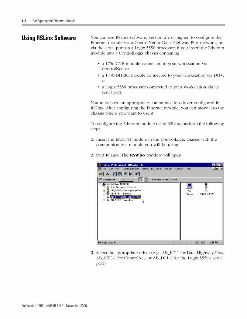
2. Start RSLinx. The RSWho window will open.
3. Select the appropriate driver (e.g., AB_KT-1 for Data Highway Plus, AB_KTC-1 for ControlNet, or AB_DF1-1 for the Logix 5550’s serial port).
Publication 1756-UM051B-EN-P - November 2000
Configuring the Ethernet Module 4-3
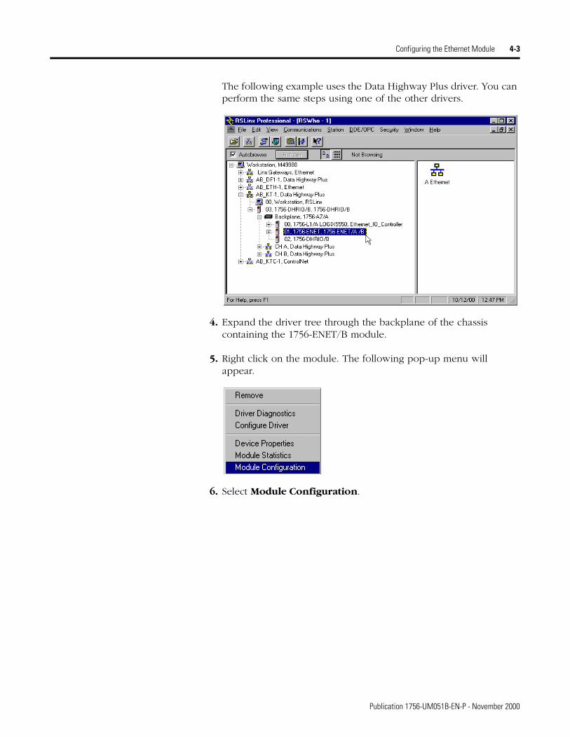
The following example uses the Data Highway Plus driver. You can perform the same steps using one of the other drivers.
4. Expand the driver tree through the backplane of the chassis containing the 1756-ENET/B module.
5. Right click on the module. The following pop-up menu will appear.
6. Select Module Configuration.
Publication 1756-UM051B-EN-P - November 2000
4-4 Configuring the Ethernet Module
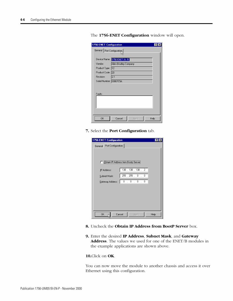
The 1756-ENET Configuration window will open.
7. Select the Port Configuration tab.
8. Uncheck the Obtain IP Address from BootP Server box.
9. Enter the desired IP Address, Subnet Mask, and Gateway Address. The values we used for one of the ENET/B modules in the example applications are shown above.
10.Click on OK.
You can now move the module to another chassis and access it over Ethernet using this configuration.
Publication 1756-UM051B-EN-P - November 2000
Configuring the Ethernet Module 4-5
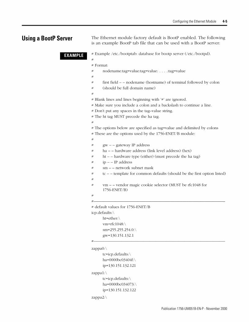
Using a BootP Server The Ethernet module factory default is BootP enabled. The following is an example BootP tab file that can be used with a BootP server:
# Example /etc./bootptab: database for bootp server (/etc./bootpd).
#
# Format:
# nodename:tag=value:tag=value: . . . .:tag=value
#
# first field – – nodename (hostname) of terminal followed by colon
# (should be full domain name)
#
# Blank lines and lines beginning with ’#’ are ignored.
# Make sure you include a colon and a backslash to continue a line.
# Don’t put any spaces in the tag–value string.
# The ht tag MUST precede the ha tag.
#
# The options below are specified as tag=value and delimited by colons
# These are the options used by the 1756-ENET/B module:
#
# gw – – gateway IP address
# ha – – hardware address (link level address) (hex)
# ht – – hardware type (either) (must precede the ha tag)
# ip – – IP address
# sm – – network subnet mask
# tc – – template for common defaults (should be the first option listed)
#
# vm – – vendor magic cookie selector (MUST be rfc1048 for 1756-ENET/B)
#
#-––––––––––––––––––––––––––––––––––––––––––––––––––––––––––––––––
# default values for 1756-ENET/B
icp.defaults:\
ht=ether:\
vm=rfc1048:\
sm=255.255.254.0:\
gw=130.151.132.1
#-––––––––––––––––––––––––––––––––––––––––––––––––––––––––––––––––
zappa0:\
tc=icp.defaults:\
ha=0000bc03404f:\
ip=130.151.132.121
zappa1:\
tc=icp.defaults:\
ha=0000bc034073:\
ip=130.151.132.122
zappa2:\
EXAMPLE
Publication 1756-UM051B-EN-P - November 2000

4-6 Configuring the Ethernet Module
tc=icp.defaults:\
ha=0000bc034022:\
ip=130.151.132.123
To use a BootP server to configure the ENET/B module perform the following steps:
1. Access and open the BootP tab file using a text editor.
2. Enter the IP address of your module.
If you need more information on setting IP addresses, refer to pages 3-3 to 3-4.
3. Use the text editor to enter the Ethernet hardware address (MAC ID) of your module. You must enter all digits, including zeroes.
If you change or replace this Ethernet module, you must enter the new Ethernet hardware address of the module when you configure the new module.
4. Enter the Gateway Address.
If you need more information on assigning gateway addresses, refer to pages 3-4 to 3-4.
5. Enter the Subnet Mask
If you need more information on selecting subnet masks, refer to pages 3-5 to 3-5.
6. After you have entered all the configuration data, save the file in a directory where the BootP server can access it.
IMPORTANT When using the BootP protocol, you must enter the Ethernet hardware address of your module. Rockwell assigns each Ethernet module a unique 48-bit hardware address at the factory. The address is printed on a label on the front of your Ethernet module as shown in the figure on the left. It consists of six hexadecimal digits separated by dots. This address is fixed by the hardware, and cannot be changed.
HardwareAddress
31153-M
AUI
10 BASET
1756-ENET
RXD TXD OK
ETHERNET
Publication 1756-UM051B-EN-P - November 2000
Configuring the Ethernet Module 4-7
Using DHCP Software to Configure Your Module
DHCP (Dynamic Host Configuration Protocol) software automatically assigns IP addresses to client stations logging onto a TCP/IP network. DHCP is based on BootP and maintains some backward compatibility. The main difference is that BootP was designed for manual configuration, while DHCP allows for dynamic allocation of network addresses and configurations to newly attached devices.
Be cautious about using DHCP software to configure your module. A BootP client, such as the 1756-ENET/B module, can boot from a DHCP server only if the DHCP server is specifically written to also handle BootP queries. This is specific to the DHCP software package you use. Check with your system administrator to see if your DHCP package supports BootP commands and manual IP allocation.
What’s Next? The following chapter describes an example application in which you configure remote digital I/O using a rack optimized connection.
ATTENTION
!The 1756-ENET/B module must be assigned a fixed network address. The IP address of this module must not be dynamically provided.
Failure to observe this precaution may result in unintended machine motion or loss of process control.
Publication 1756-UM051B-EN-P - November 2000

4-8 Configuring the Ethernet Module
Publication 1756-UM051B-EN-P - November 2000
Chapter 5
Rack Optimized I/O
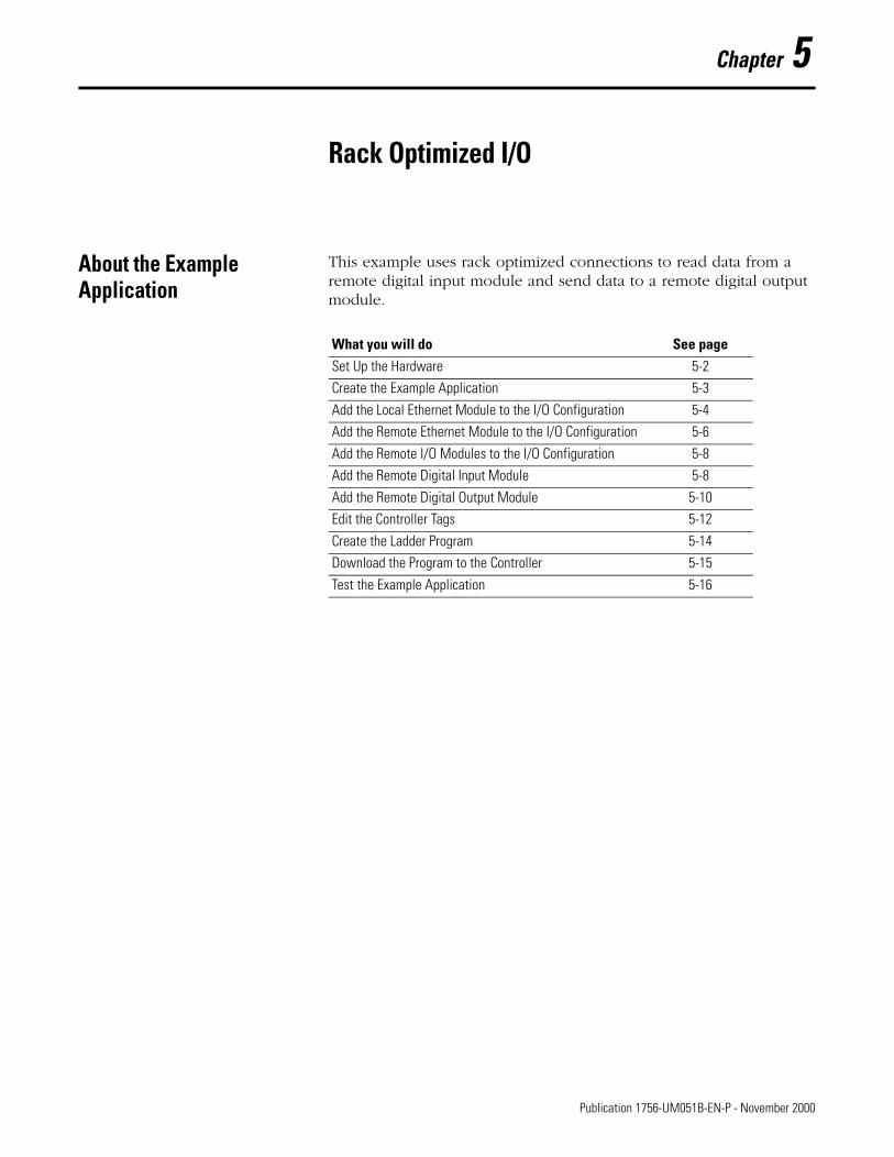
About the Example Application
This example uses rack optimized connections to read data from a remote digital input module and send data to a remote digital output module.
What you will do See pageSet Up the Hardware 5-2Create the Example Application 5-3
Add the Local Ethernet Module to the I/O Configuration 5-4Add the Remote Ethernet Module to the I/O Configuration 5-6
Add the Remote I/O Modules to the I/O Configuration 5-8Add the Remote Digital Input Module 5-8
Add the Remote Digital Output Module 5-10Edit the Controller Tags 5-12
Create the Ladder Program 5-14Download the Program to the Controller 5-15
Test the Example Application 5-16
1 Publication 1756-UM051B-EN-P - November 2000
5-2 Rack Optimized I/O
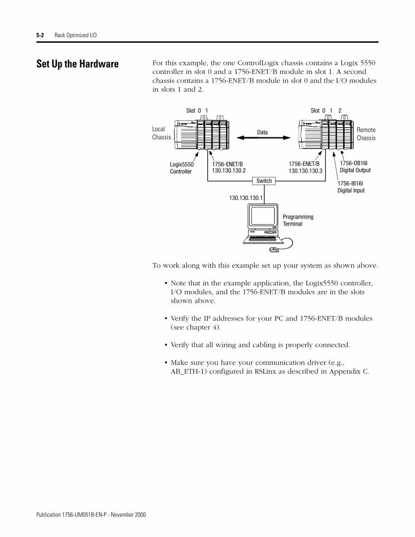
Set Up the Hardware For this example, the one ControlLogix chassis contains a Logix 5550 controller in slot 0 and a 1756-ENET/B module in slot 1. A second chassis contains a 1756-ENET/B module in slot 0 and the I/O modules in slots 1 and 2.
To work along with this example set up your system as shown above.
• Note that in the example application, the Logix5550 controller, I/O modules, and the 1756-ENET/B modules are in the slots shown above.
• Verify the IP addresses for your PC and 1756-ENET/B modules (see chapter 4).
• Verify that all wiring and cabling is properly connected.
• Make sure you have your communication driver (e.g., AB_ETH-1) configured in RSLinx as described in Appendix C.
Logix5550 1756-ENET/B 1756-ENET/B
Data
Slot 0 1 Slot 0 1 2
1756-IB16IDigital Input
1756-OB16IDigital OutputController
Switch
Programming
130.130.130.1
130.130.130.2 130.130.130.3
Terminal
Local Chassis
Remote Chassis
Publication 1756-UM051B-EN-P - November 2000
Rack Optimized I/O 5-3
Create the Example Application
Perform the following steps to create the example application:
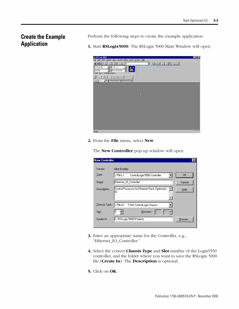
1. Start RSLogix5000. The RSLogix 5000 Main Window will open.
2. From the File menu, select New.
The New Controller pop-up window will open.
3. Enter an appropriate name for the Controller, e.g., “Ethernet_IO_Controller.”
4. Select the correct Chassis Type and Slot number of the Logix5550 controller, and the folder where you want to save the RSLogix 5000 file (Create In). The Description is optional.
5. Click on OK.
Publication 1756-UM051B-EN-P - November 2000
5-4 Rack Optimized I/O
You now add the remote digital I/O modules to the controller’s I/O configuration. To do this you first add the local 1756-ENET/B module to the I/O configuration. Next you add the 1756-ENET/B in the remote chassis with the digital I/O modules as a “child” of the local 1756-ENET/B module. Then you add the I/O modules as “children” of the remote 1756-ENET/B module.
Add the Local Ethernet Module to the I/O Configuration
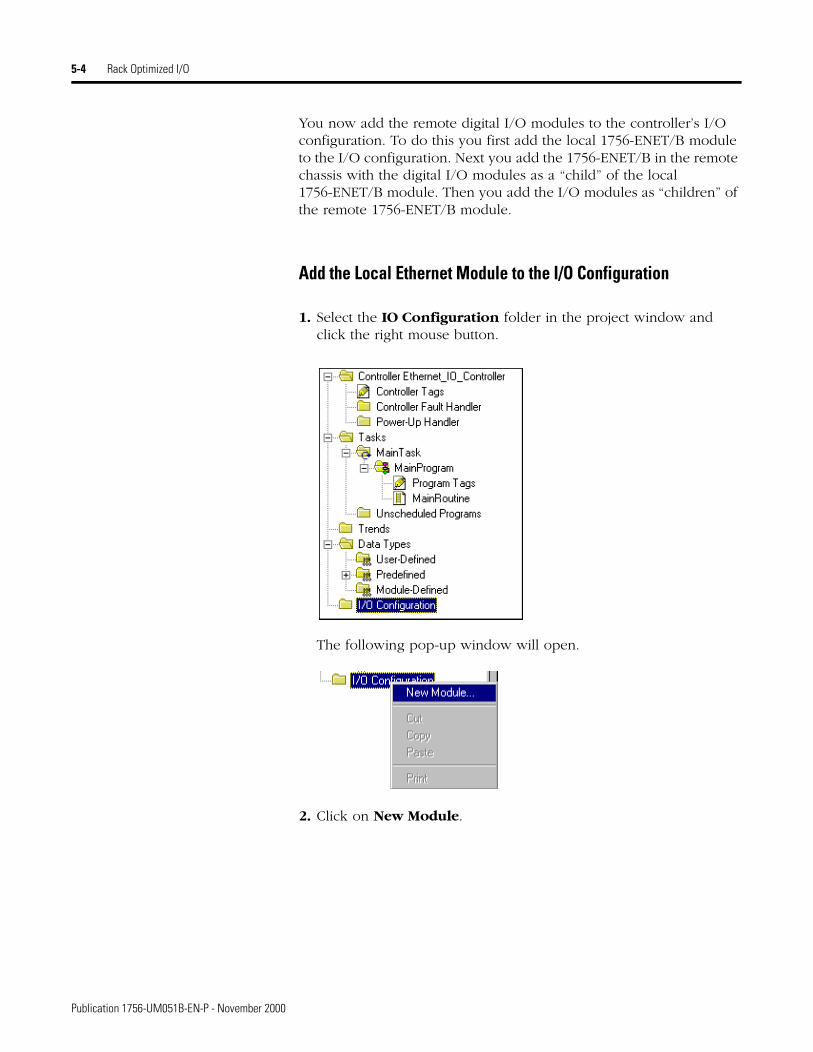
1. Select the IO Configuration folder in the project window and click the right mouse button.
The following pop-up window will open.
2. Click on New Module.
Publication 1756-UM051B-EN-P - November 2000
Rack Optimized I/O 5-5
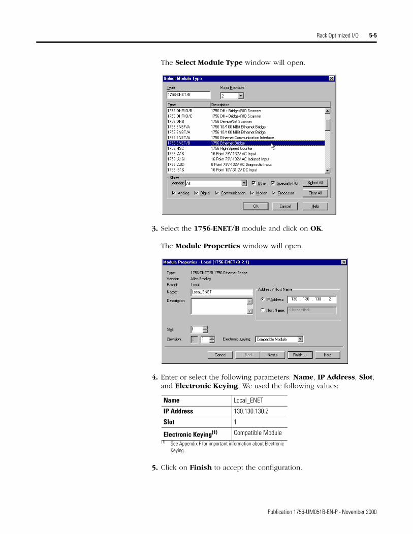
The Select Module Type window will open.
3. Select the 1756-ENET/B module and click on OK.
The Module Properties window will open.
4. Enter or select the following parameters: Name, IP Address, Slot, and Electronic Keying. We used the following values:
5. Click on Finish to accept the configuration.
Name Local_ENET
IP Address 130.130.130.2
Slot 1
Electronic Keying(1)
(1) See Appendix F for important information about Electronic Keying.
Compatible Module
Publication 1756-UM051B-EN-P - November 2000
5-6 Rack Optimized I/O
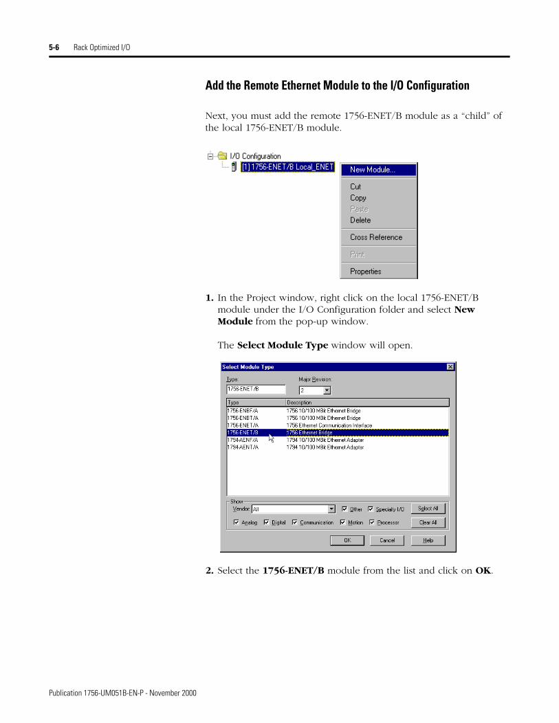
Add the Remote Ethernet Module to the I/O Configuration
Next, you must add the remote 1756-ENET/B module as a “child” of the local 1756-ENET/B module.
1. In the Project window, right click on the local 1756-ENET/B module under the I/O Configuration folder and select New Module from the pop-up window.
The Select Module Type window will open.
2. Select the 1756-ENET/B module from the list and click on OK.
Publication 1756-UM051B-EN-P - November 2000
Rack Optimized I/O 5-7
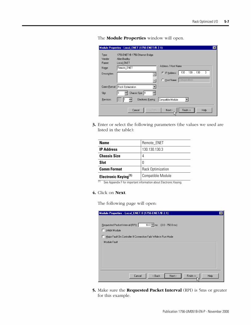
The Module Properties window will open.
3. Enter or select the following parameters (the values we used are listed in the table):
4. Click on Next.
The following page will open:
5. Make sure the Requested Packet Interval (RPI) is 5ms or greater for this example.
Name Remote_ENET
IP Address 130.130.130.3
Chassis Size 4
Slot 0
Comm Format Rack Optimization
Electronic Keying(1)
(1) See Appendix F for important information about Electronic Keying.
Compatible Module
Publication 1756-UM051B-EN-P - November 2000
5-8 Rack Optimized I/O
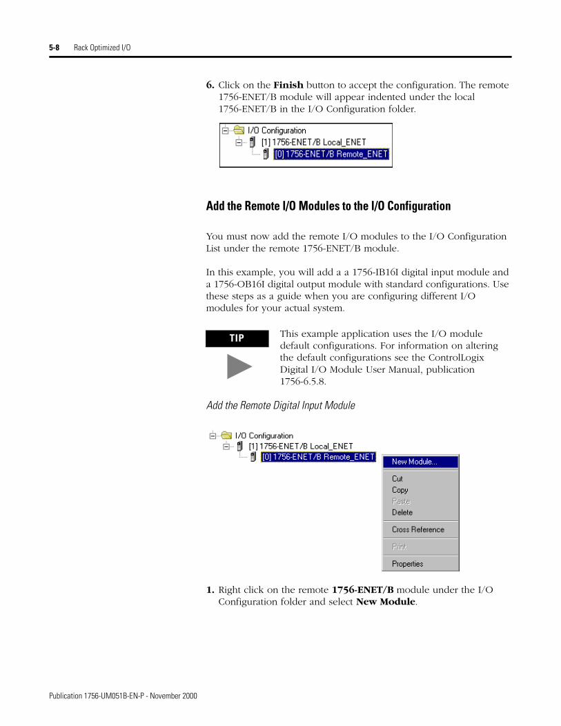
6. Click on the Finish button to accept the configuration. The remote 1756-ENET/B module will appear indented under the local 1756-ENET/B in the I/O Configuration folder.
Add the Remote I/O Modules to the I/O Configuration
You must now add the remote I/O modules to the I/O Configuration List under the remote 1756-ENET/B module.
In this example, you will add a a 1756-IB16I digital input module and a 1756-OB16I digital output module with standard configurations. Use these steps as a guide when you are configuring different I/O modules for your actual system.
Add the Remote Digital Input Module
1. Right click on the remote 1756-ENET/B module under the I/O Configuration folder and select New Module.
TIP This example application uses the I/O module default configurations. For information on altering the default configurations see the ControlLogix Digital I/O Module User Manual, publication 1756-6.5.8.
Publication 1756-UM051B-EN-P - November 2000
Rack Optimized I/O 5-9
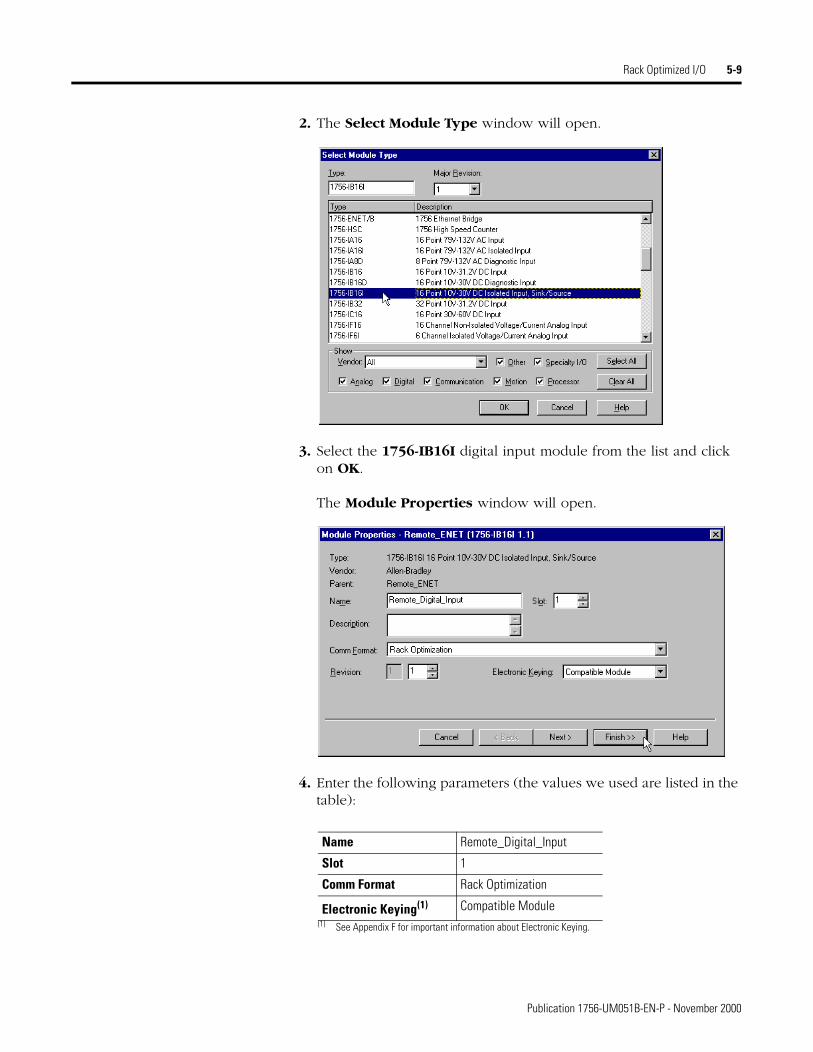
2. The Select Module Type window will open.
3. Select the 1756-IB16I digital input module from the list and click on OK.
The Module Properties window will open.
4. Enter the following parameters (the values we used are listed in the table):
Name Remote_Digital_Input
Slot 1
Comm Format Rack Optimization
Electronic Keying(1)
(1) See Appendix F for important information about Electronic Keying.
Compatible Module
Publication 1756-UM051B-EN-P - November 2000
5-10 Rack Optimized I/O
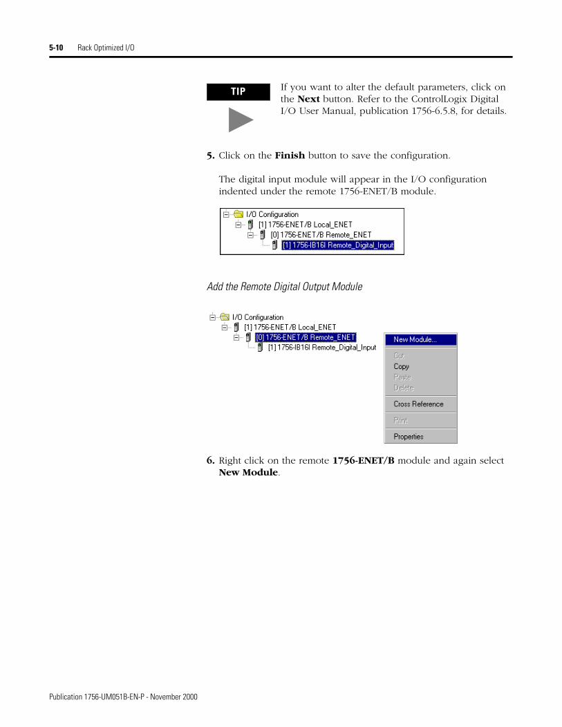
5. Click on the Finish button to save the configuration.
The digital input module will appear in the I/O configuration indented under the remote 1756-ENET/B module.
Add the Remote Digital Output Module
6. Right click on the remote 1756-ENET/B module and again select New Module.
TIP If you want to alter the default parameters, click on the Next button. Refer to the ControlLogix Digital I/O User Manual, publication 1756-6.5.8, for details.
Publication 1756-UM051B-EN-P - November 2000
Rack Optimized I/O 5-11
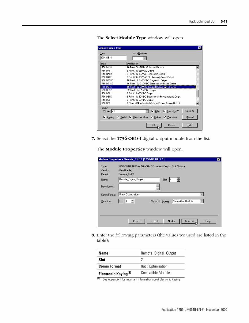
The Select Module Type window will open.
7. Select the 1756-OB16I digital output module from the list.
The Module Properties window will open.
8. Enter the following parameters (the values we used are listed in the table):
Name Remote_Digital_Output
Slot 2
Comm Format Rack Optimization
Electronic Keying(1)
(1) See Appendix F for important information about Electronic Keying.
Compatible Module
Publication 1756-UM051B-EN-P - November 2000
5-12 Rack Optimized I/O
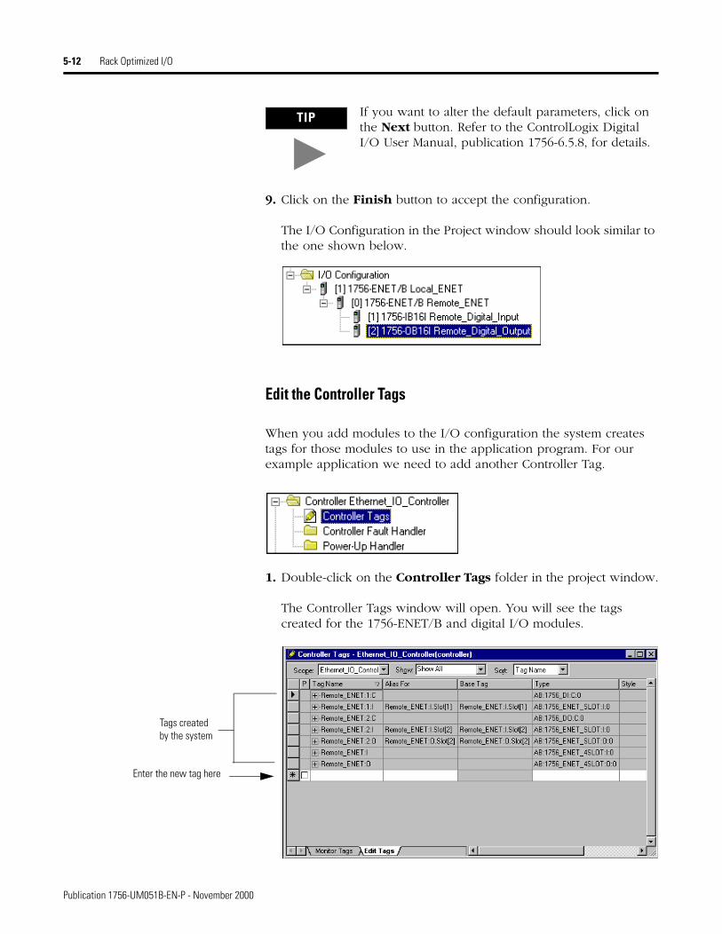
9. Click on the Finish button to accept the configuration.
The I/O Configuration in the Project window should look similar to the one shown below.
Edit the Controller Tags
When you add modules to the I/O configuration the system creates tags for those modules to use in the application program. For our example application we need to add another Controller Tag.
1. Double-click on the Controller Tags folder in the project window.
The Controller Tags window will open. You will see the tags created for the 1756-ENET/B and digital I/O modules.
TIP If you want to alter the default parameters, click on the Next button. Refer to the ControlLogix Digital I/O User Manual, publication 1756-6.5.8, for details.
Enter the new tag here
Tags created by the system
Publication 1756-UM051B-EN-P - November 2000
Rack Optimized I/O 5-13
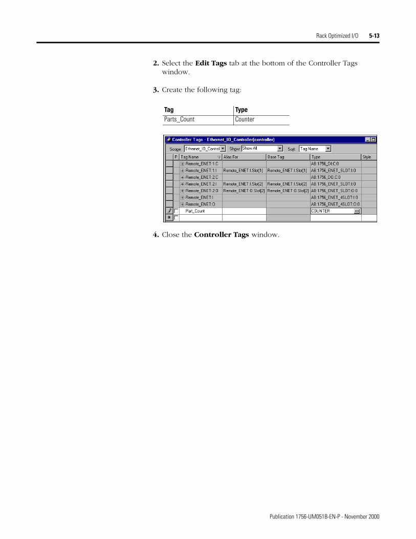
2. Select the Edit Tags tab at the bottom of the Controller Tags window.
3. Create the following tag:
4. Close the Controller Tags window.
Tag TypeParts_Count Counter
Publication 1756-UM051B-EN-P - November 2000
5-14 Rack Optimized I/O
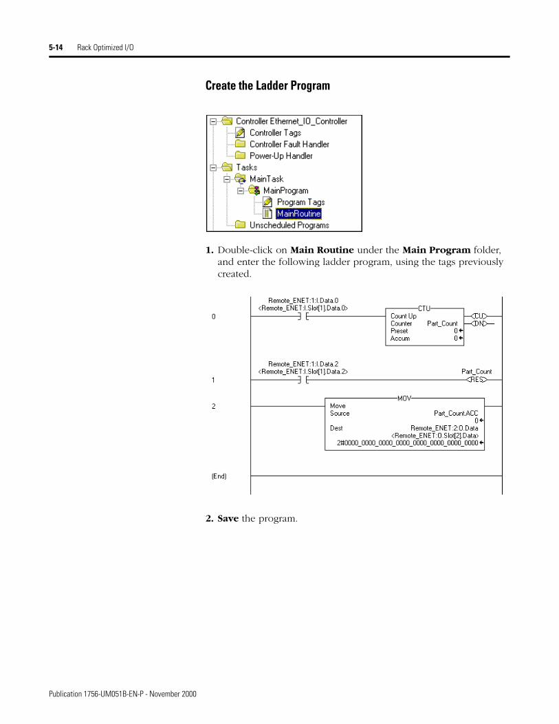
Create the Ladder Program
1. Double-click on Main Routine under the Main Program folder, and enter the following ladder program, using the tags previously created.
2. Save the program.
Publication 1756-UM051B-EN-P - November 2000
Rack Optimized I/O 5-15
Download the Program to the Controller
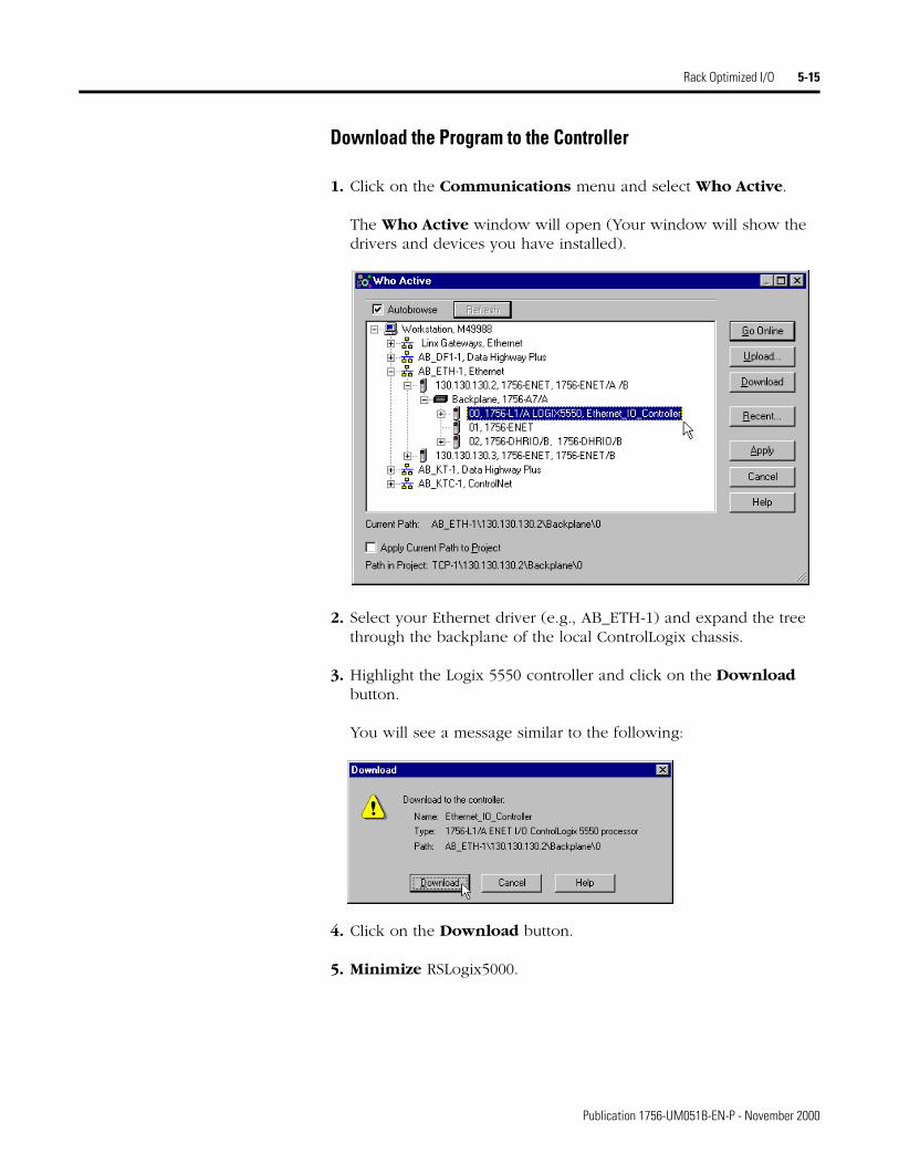
1. Click on the Communications menu and select Who Active.
The Who Active window will open (Your window will show the drivers and devices you have installed).
2. Select your Ethernet driver (e.g., AB_ETH-1) and expand the tree through the backplane of the local ControlLogix chassis.
3. Highlight the Logix 5550 controller and click on the Download button.
You will see a message similar to the following:
4. Click on the Download button.
5. Minimize RSLogix5000.
Publication 1756-UM051B-EN-P - November 2000
5-16 Rack Optimized I/O
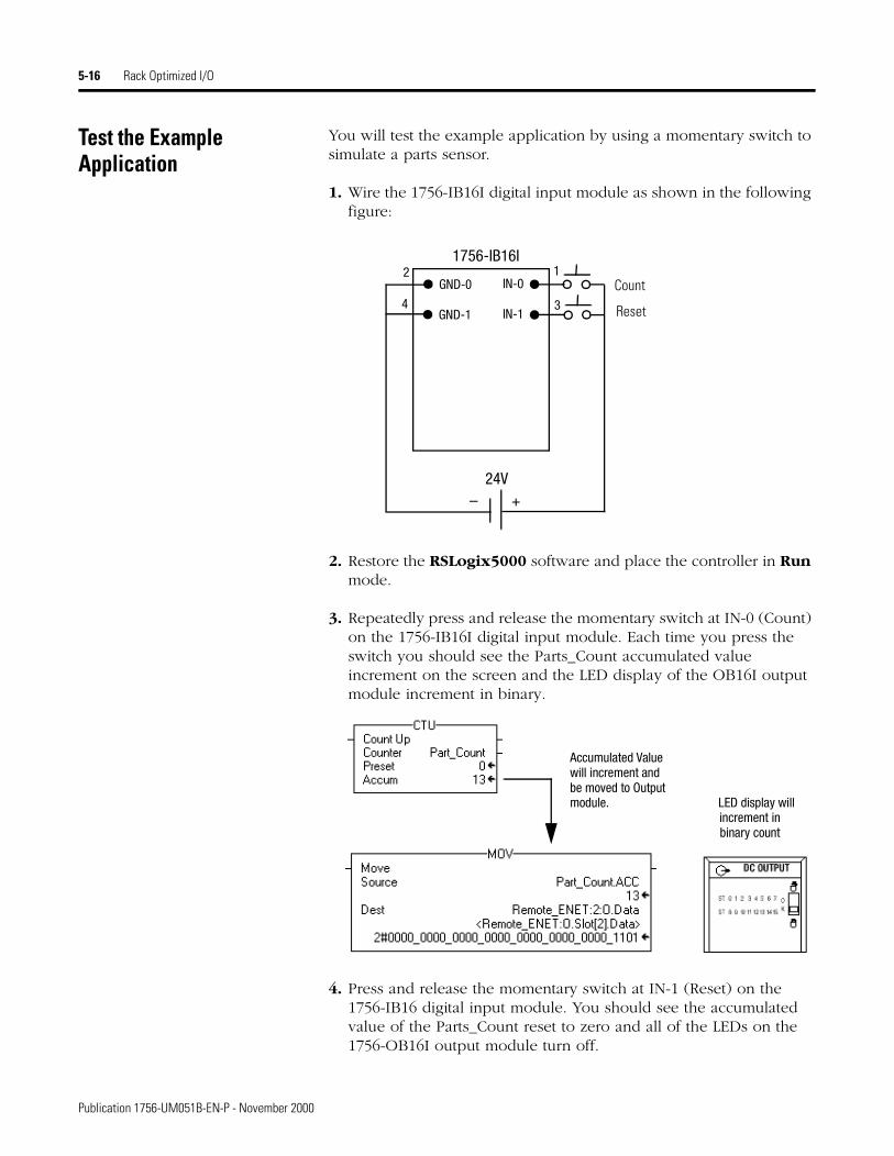
Test the Example Application
You will test the example application by using a momentary switch to simulate a parts sensor.
1. Wire the 1756-IB16I digital input module as shown in the following figure:
2. Restore the RSLogix5000 software and place the controller in Run mode.
3. Repeatedly press and release the momentary switch at IN-0 (Count) on the 1756-IB16I digital input module. Each time you press the switch you should see the Parts_Count accumulated value increment on the screen and the LED display of the OB16I output module increment in binary.
4. Press and release the momentary switch at IN-1 (Reset) on the 1756-IB16 digital input module. You should see the accumulated value of the Parts_Count reset to zero and all of the LEDs on the 1756-OB16I output module turn off.
IN-0
IN-1
GND-01
3
2
+–
1756-IB16I
24V
Count
ResetGND-14
Accumulated Valuewill increment andbe moved to Outputmodule. LED display will
increment inbinary count
Publication 1756-UM051B-EN-P - November 2000

Rack Optimized I/O 5-17
This completes the Rack Optimized I/O example.
What’s Next? The following chapter describes an example application in which you add an analog output module to the I/O configuration using a direct connection.
TIP Refer to the ControlLogix Digital I/O Modules User Manual, publication 1756-6.5.8, for assistance in wiring and debugging the I/O modules.
Publication 1756-UM051B-EN-P - November 2000

5-18 Rack Optimized I/O
Publication 1756-UM051B-EN-P - November 2000
Chapter 6
Analog I/O with Direct Connection
About the Example Application
In this example you add an analog output module to the remote chassis containing the 1756-ENET/B module and the two digital I/O modules configured in the previous chapter. Analog modules default to direct connection. Note that you will open a direct connection to the analog module while still using a single rack optimized connection for the two digital I/O modules.
To test the connection the RSLogix 5000 project of the previous chapter is modified to produce a varying signal at one of the analog output channels.
What you will do See page
Set Up the Hardware 6-2
Create the Example Application 6-3Add the Remote Analog I/O Module to the I/O Configuration 6-4
Edit the Controller Tags 6-8Modify the Ladder Program 6-10
Download the Program 6-11Test the Example Application 6-12
1 Publication 1756-UM051B-EN-P - November 2000
6-2 Analog I/O with Direct Connection
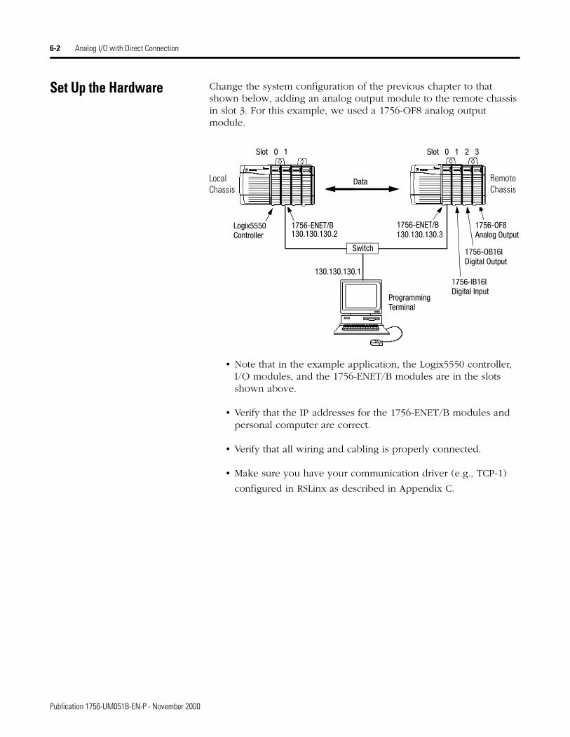
Set Up the Hardware Change the system configuration of the previous chapter to that shown below, adding an analog output module to the remote chassis in slot 3. For this example, we used a 1756-OF8 analog output module.
• Note that in the example application, the Logix5550 controller, I/O modules, and the 1756-ENET/B modules are in the slots shown above.
• Verify that the IP addresses for the 1756-ENET/B modules and personal computer are correct.
• Verify that all wiring and cabling is properly connected.
• Make sure you have your communication driver (e.g., TCP-1)
configured in RSLinx as described in Appendix C.
Logix5550 1756-ENET/B 1756-ENET/B
Data
Slot 0 1 Slot 0 1 2 3
1756-IB16IDigital Input
1756-OB16IDigital Output
Controller
Switch
Programming
130.130.130.1
130.130.130.2 130.130.130.3
Terminal
Local Chassis
Remote Chassis
1756-OF8Analog Output
Publication 1756-UM051B-EN-P - November 2000
Analog I/O with Direct Connection 6-3
Create the Example Application
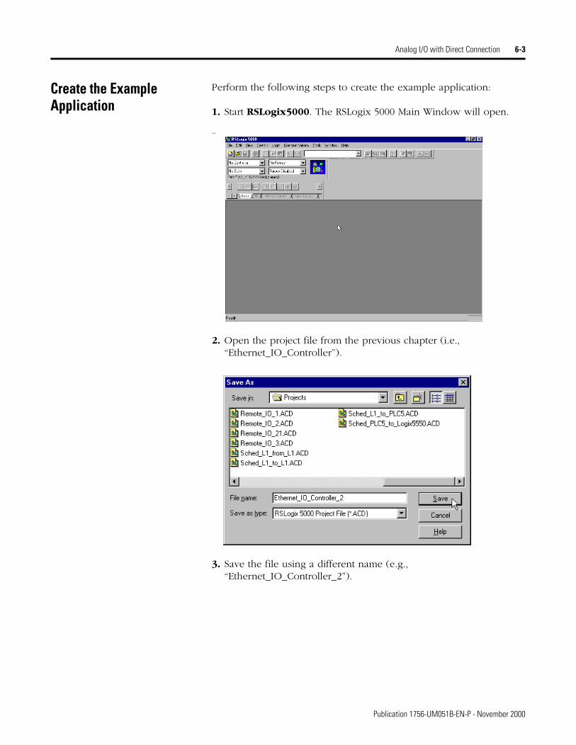
Perform the following steps to create the example application:
1. Start RSLogix5000. The RSLogix 5000 Main Window will open.
Open
2. Open the project file from the previous chapter (i.e., “Ethernet_IO_Controller”).
3. Save the file using a different name (e.g., “Ethernet_IO_Controller_2”).
Publication 1756-UM051B-EN-P - November 2000
6-4 Analog I/O with Direct Connection
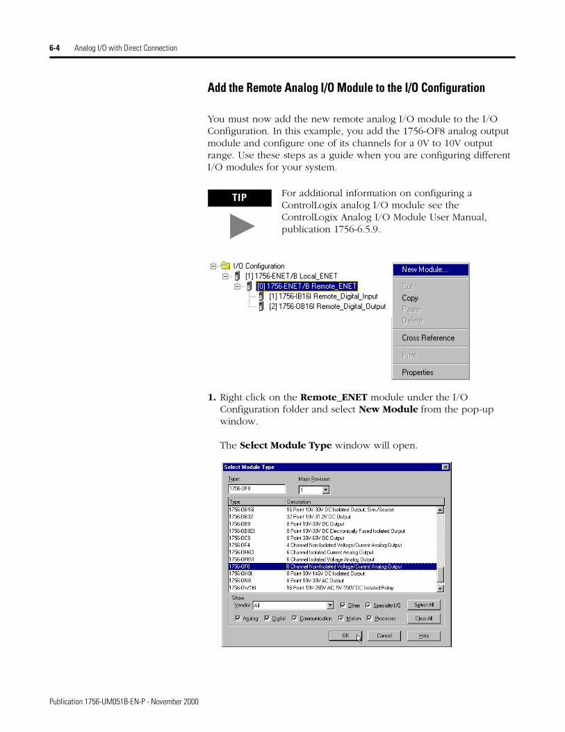
Add the Remote Analog I/O Module to the I/O Configuration
You must now add the new remote analog I/O module to the I/O Configuration. In this example, you add the 1756-OF8 analog output module and configure one of its channels for a 0V to 10V output range. Use these steps as a guide when you are configuring different I/O modules for your system.
1. Right click on the Remote_ENET module under the I/O Configuration folder and select New Module from the pop-up window.
The Select Module Type window will open.
TIP For additional information on configuring a ControlLogix analog I/O module see the ControlLogix Analog I/O Module User Manual, publication 1756-6.5.9.
Publication 1756-UM051B-EN-P - November 2000
Analog I/O with Direct Connection 6-5
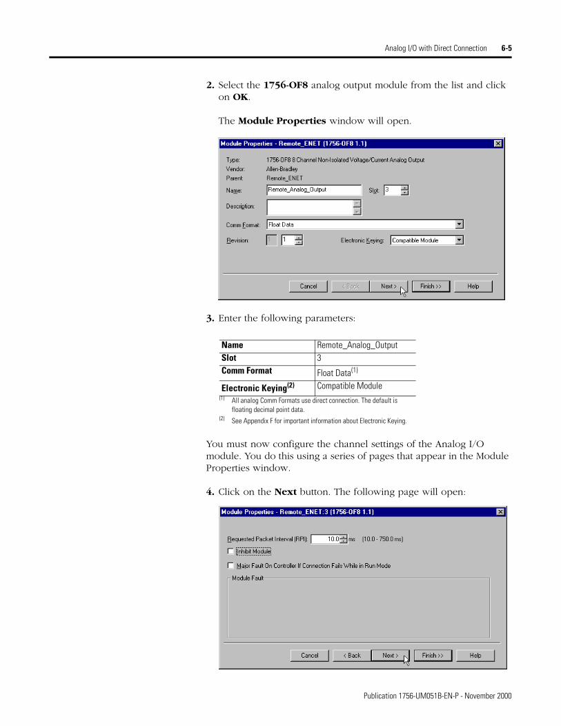
2. Select the 1756-OF8 analog output module from the list and click on OK.
The Module Properties window will open.
3. Enter the following parameters:
You must now configure the channel settings of the Analog I/O module. You do this using a series of pages that appear in the Module Properties window.
4. Click on the Next button. The following page will open:
Name Remote_Analog_OutputSlot 3Comm Format Float Data(1)
(1) All analog Comm Formats use direct connection. The default is floating decimal point data.
Electronic Keying(2)
(2) See Appendix F for important information about Electronic Keying.
Compatible Module
Publication 1756-UM051B-EN-P - November 2000
6-6 Analog I/O with Direct Connection
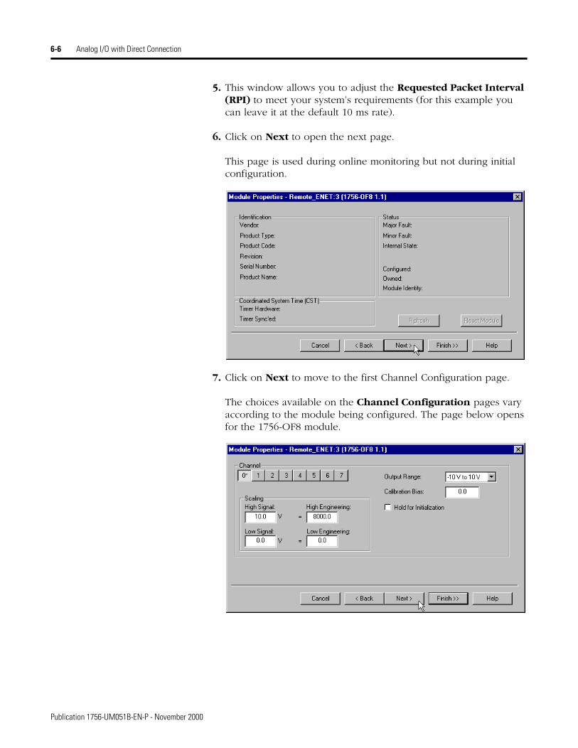
5. This window allows you to adjust the Requested Packet Interval (RPI) to meet your system’s requirements (for this example you can leave it at the default 10 ms rate).
6. Click on Next to open the next page.
This page is used during online monitoring but not during initial configuration.
.
7. Click on Next to move to the first Channel Configuration page.
The choices available on the Channel Configuration pages vary according to the module being configured. The page below opens for the 1756-OF8 module.
Publication 1756-UM051B-EN-P - November 2000
Analog I/O with Direct Connection 6-7
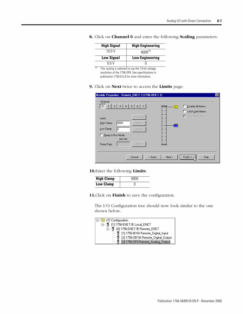
8. Click on Channel 0 and enter the following Scaling parameters:
9. Click on Next twice to access the Limits page.
10.Enter the following Limits:
11.Click on Finish to save the configuration.
The I/O Configuration tree should now look similar to the one shown below.
High Signal High Engineering10.0 V 8000(1)
(1) This scaling is selected to use the 13-bit voltage resolution of the 1756-OF8. See specifications in publication 1756-6.5.9 for more information.
Low Signal Low Engineering0.0 V 0
High Clamp 8000Low Clamp 0
Publication 1756-UM051B-EN-P - November 2000
6-8 Analog I/O with Direct Connection
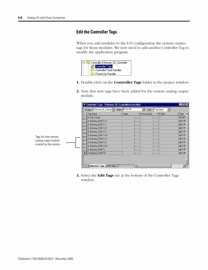
Edit the Controller Tags
When you add modules to the I/O configuration the system creates tags for those modules. We now need to add another Controller Tag to modify the application program.
1. Double-click on the Controller Tags folder in the project window.
2. Note that new tags have been added for the remote analog output module.
3. Select the Edit Tags tab at the bottom of the Controller Tags window.
Tags for new remote analog output module created by the system.
Publication 1756-UM051B-EN-P - November 2000
Analog I/O with Direct Connection 6-9
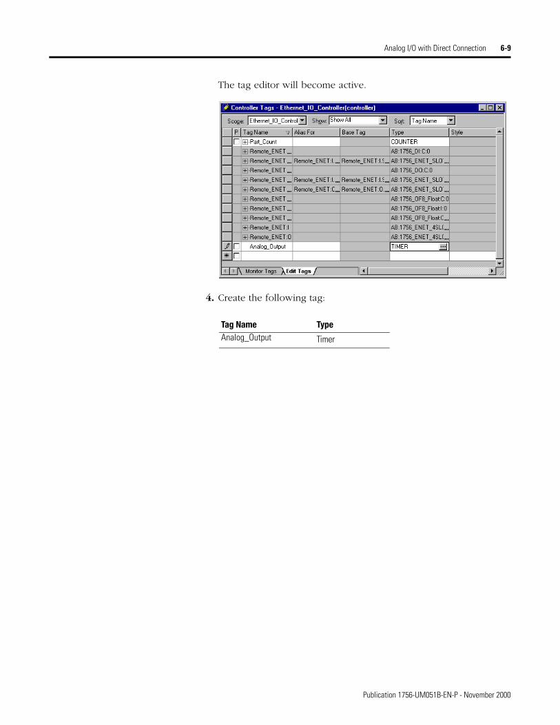
The tag editor will become active.
4. Create the following tag:
Tag Name TypeAnalog_Output Timer
Publication 1756-UM051B-EN-P - November 2000
6-10 Analog I/O with Direct Connection
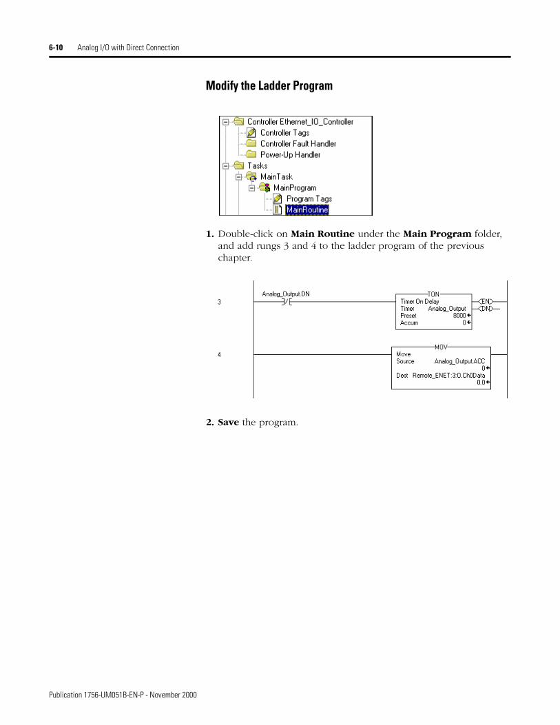
Modify the Ladder Program
1. Double-click on Main Routine under the Main Program folder, and add rungs 3 and 4 to the ladder program of the previous chapter.
2. Save the program.
Publication 1756-UM051B-EN-P - November 2000
Analog I/O with Direct Connection 6-11
Download the Program
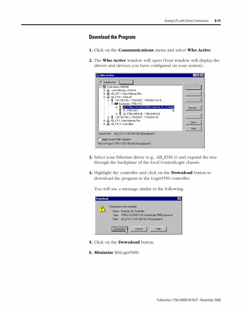
1. Click on the Communications menu and select Who Active.
2. The Who Active window will open (Your window will display the drivers and devices you have configured on your system).
3. Select your Ethernet driver (e.g., AB_ETH-1) and expand the tree through the backplane of the local ControlLogix chassis.
4. Highlight the controller and click on the Download button to download the program to the Logix5550 controller.
You will see a message similar to the following:
5. Click on the Download button.
6. Minimize RSLogix5000.
Publication 1756-UM051B-EN-P - November 2000

6-12 Analog I/O with Direct Connection
Test the Example Application
Use the following procedure to test the operation of the remote analog output:
1. Connect a voltmeter across the channel 0 output of the 1756-OF8 analog output module as shown in the following figure:
2. Restore RSLogix5000 and place the controller in Run mode.
3. Measure the output voltage of channel 0. You should see it slowly rise to approximately 10V, reset to zero, start rising again, etc.
This completes the Direct Connect I/O example.
What’s Next? The following chapter describes an example application in which one controller sends a message to another controller using produced and consumed tags.
TIP Refer to the ControlLogix Analog I/O Module User Manual, publication 1756-6.5.9, for assistance in wiring and debugging the I/O modules.
VOUT-0
RTN
1
5
1756-OF8
V
+
–
Publication 1756-UM051B-EN-P - November 2000
Chapter 7
Produced and Consumed Tags
About the Example Application
In this example one Logix5550 controller (the producer) sends data to another Logix5550 controller (the consumer) over the Ethernet network. A Timer provides the test data for the message.
What you will do See page
Set Up the Hardware 7-2Create the Producer Application 7-3
Create the Producer Tags 7-4Create the Producer Ladder Program 7-6
Download the Producer Application 7-7Create the Consumer Application 7-8
Create the Consumer Controller 7-8Add the Producer to the Consumer’s I/O Configuration 7-9
Add the Local ENET/B Module to the I/O Configuration 7-9Add the Remote ENET/B Module to the I/O Configuration 7-11
Add the Remote (Producer) Controller to the I/O Configuration 7-13
Create the Consumer Tags 7-15Download the Configuration to the Consumer 7-18
Test the Messaging 7-19
1 Publication 1756-UM051B-EN-P - November 2000
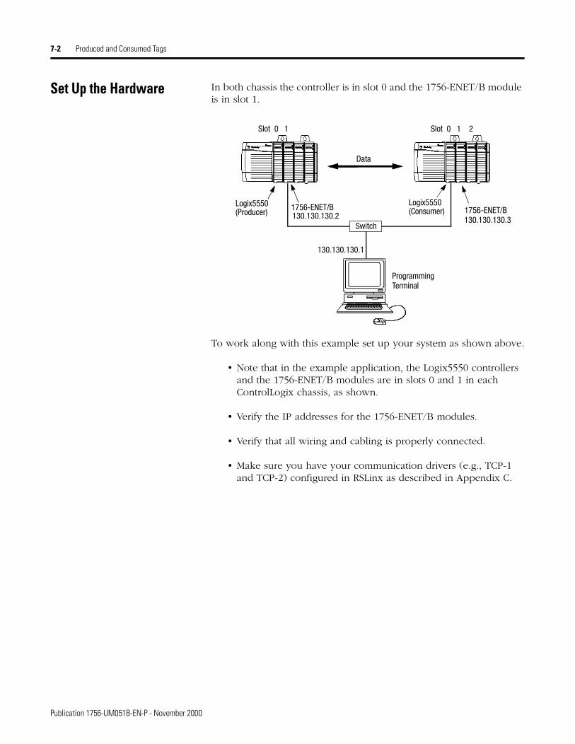
7-2 Produced and Consumed Tags
Set Up the Hardware In both chassis the controller is in slot 0 and the 1756-ENET/B module is in slot 1.
To work along with this example set up your system as shown above.
• Note that in the example application, the Logix5550 controllers and the 1756-ENET/B modules are in slots 0 and 1 in each ControlLogix chassis, as shown.
• Verify the IP addresses for the 1756-ENET/B modules.
• Verify that all wiring and cabling is properly connected.
• Make sure you have your communication drivers (e.g., TCP-1 and TCP-2) configured in RSLinx as described in Appendix C.
Logix5550 1756-ENET/B 1756-ENET/B
Data
Slot 0 1 Slot 0 1 2
Switch
Programming
130.130.130.1
130.130.130.2 130.130.130.3(Producer)
Logix5550(Consumer)
Terminal
Publication 1756-UM051B-EN-P - November 2000
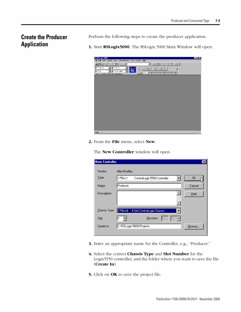
Produced and Consumed Tags 7-3
Create the Producer Application
Perform the following steps to create the producer application.
1. Start RSLogix5000. The RSLogix 5000 Main Window will open.
2. From the File menu, select New.
The New Controller window will open.
3. Enter an appropriate name for the Controller, e.g., “Producer.”
4. Select the correct Chassis Type and Slot Number for the Logix5550 controller, and the folder where you want to save the file (Create In).
5. Click on OK to save the project file.
Publication 1756-UM051B-EN-P - November 2000
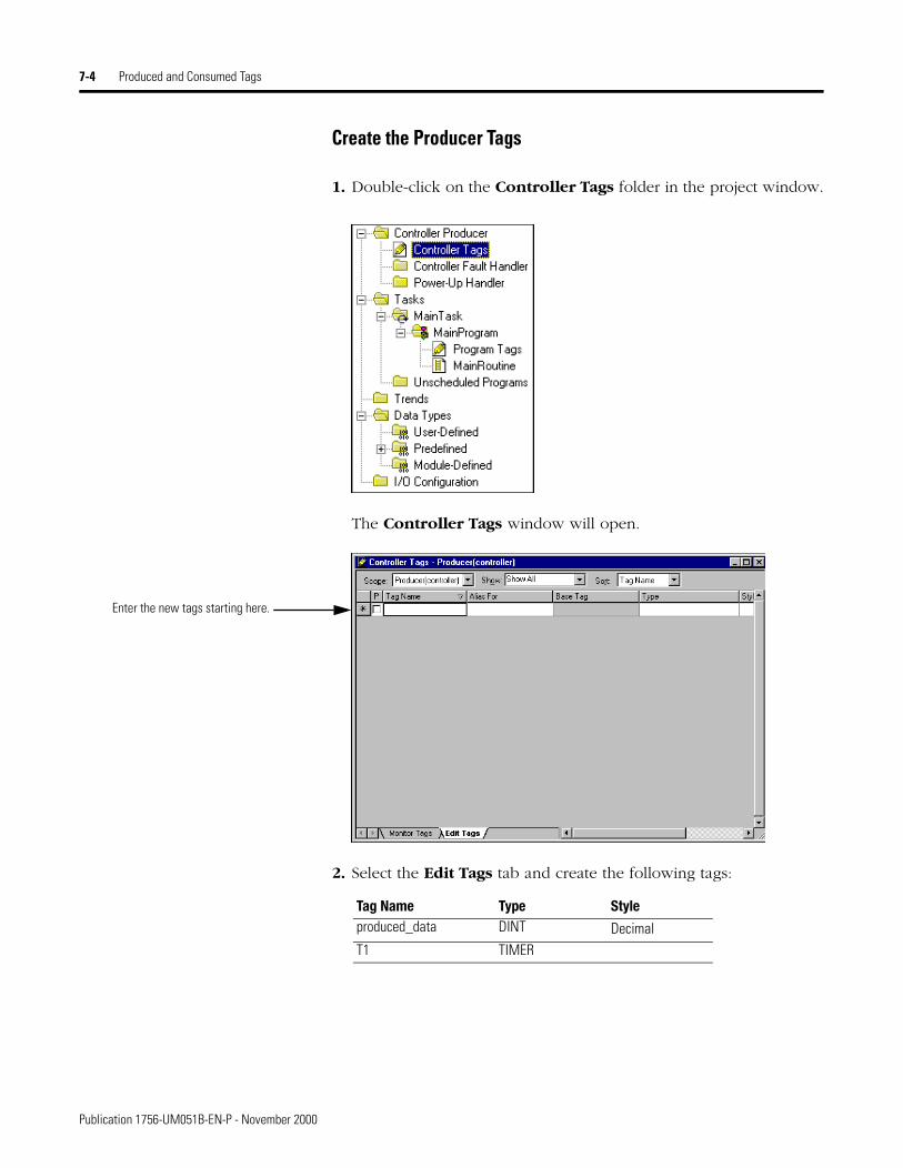
7-4 Produced and Consumed Tags
Create the Producer Tags
1. Double-click on the Controller Tags folder in the project window.
The Controller Tags window will open.
2. Select the Edit Tags tab and create the following tags:
Enter the new tags starting here.
Tag Name Type Styleproduced_data DINT DecimalT1 TIMER
Publication 1756-UM051B-EN-P - November 2000
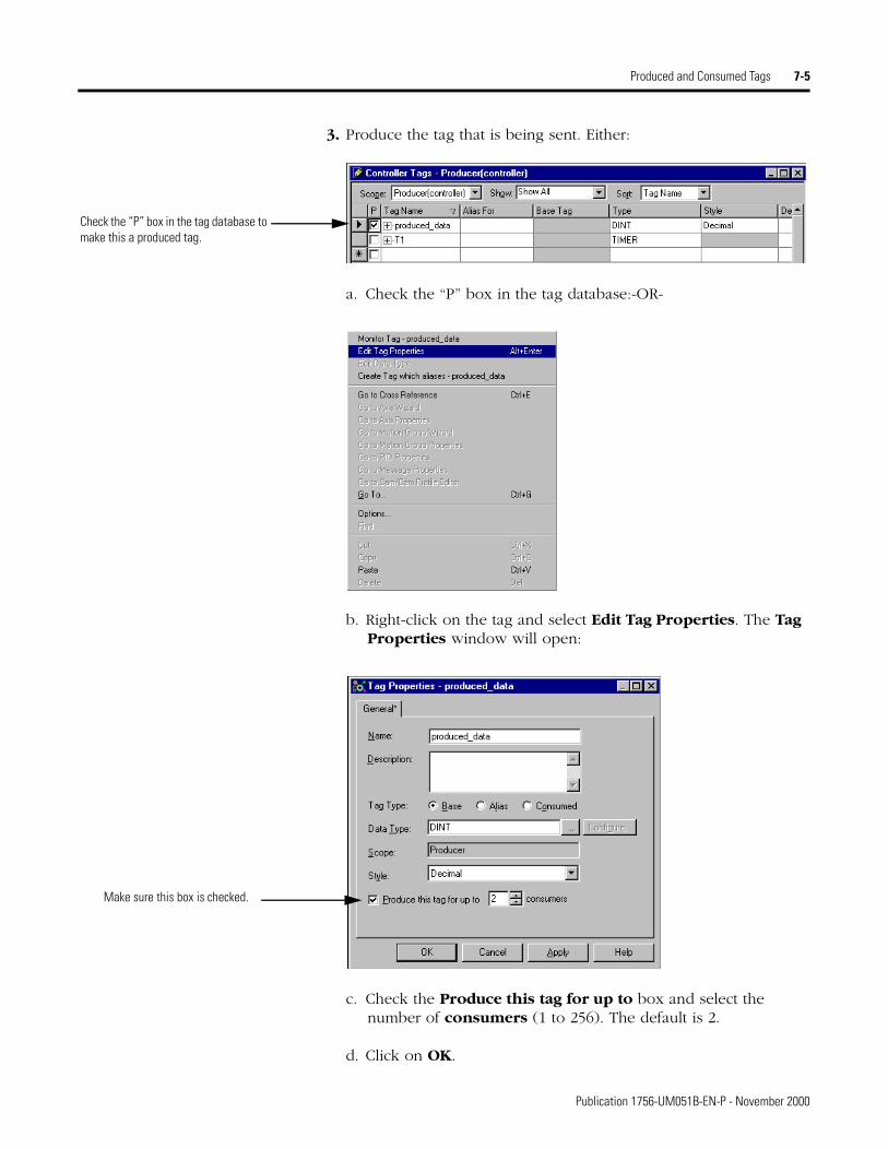
Produced and Consumed Tags 7-5
3. Produce the tag that is being sent. Either:
a. Check the “P” box in the tag database:-OR-
b. Right-click on the tag and select Edit Tag Properties. The Tag Properties window will open:
c. Check the Produce this tag for up to box and select the number of consumers (1 to 256). The default is 2.
d. Click on OK.
Check the “P” box in the tag database to make this a produced tag.
Make sure this box is checked.
Publication 1756-UM051B-EN-P - November 2000
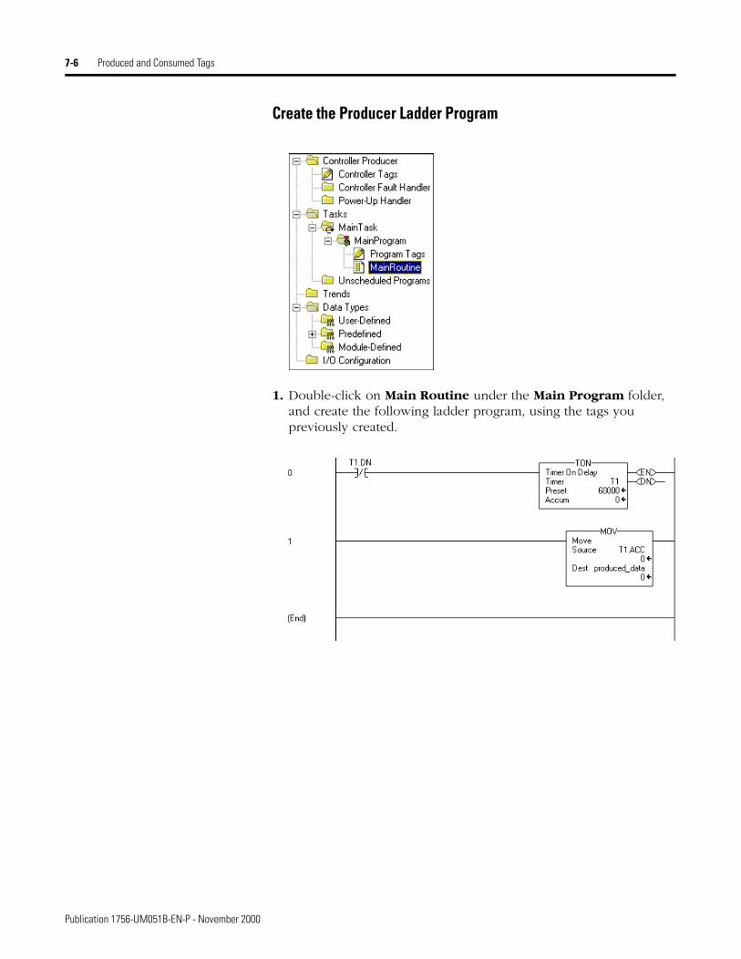
7-6 Produced and Consumed Tags
Create the Producer Ladder Program
1. Double-click on Main Routine under the Main Program folder, and create the following ladder program, using the tags you previously created.
Publication 1756-UM051B-EN-P - November 2000
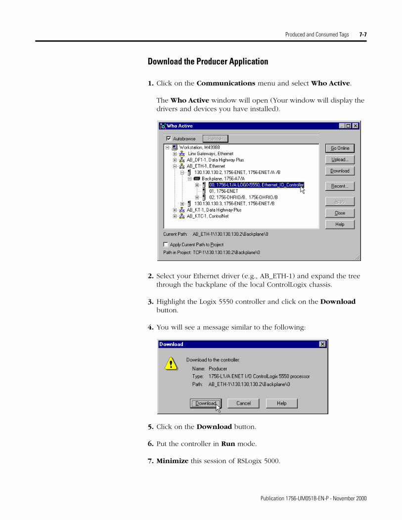
Produced and Consumed Tags 7-7
Download the Producer Application
1. Click on the Communications menu and select Who Active.
The Who Active window will open (Your window will display the drivers and devices you have installed).
2. Select your Ethernet driver (e.g., AB_ETH-1) and expand the tree through the backplane of the local ControlLogix chassis.
3. Highlight the Logix 5550 controller and click on the Download button.
4. You will see a message similar to the following:
5. Click on the Download button.
6. Put the controller in Run mode.
7. Minimize this session of RSLogix 5000.
Publication 1756-UM051B-EN-P - November 2000
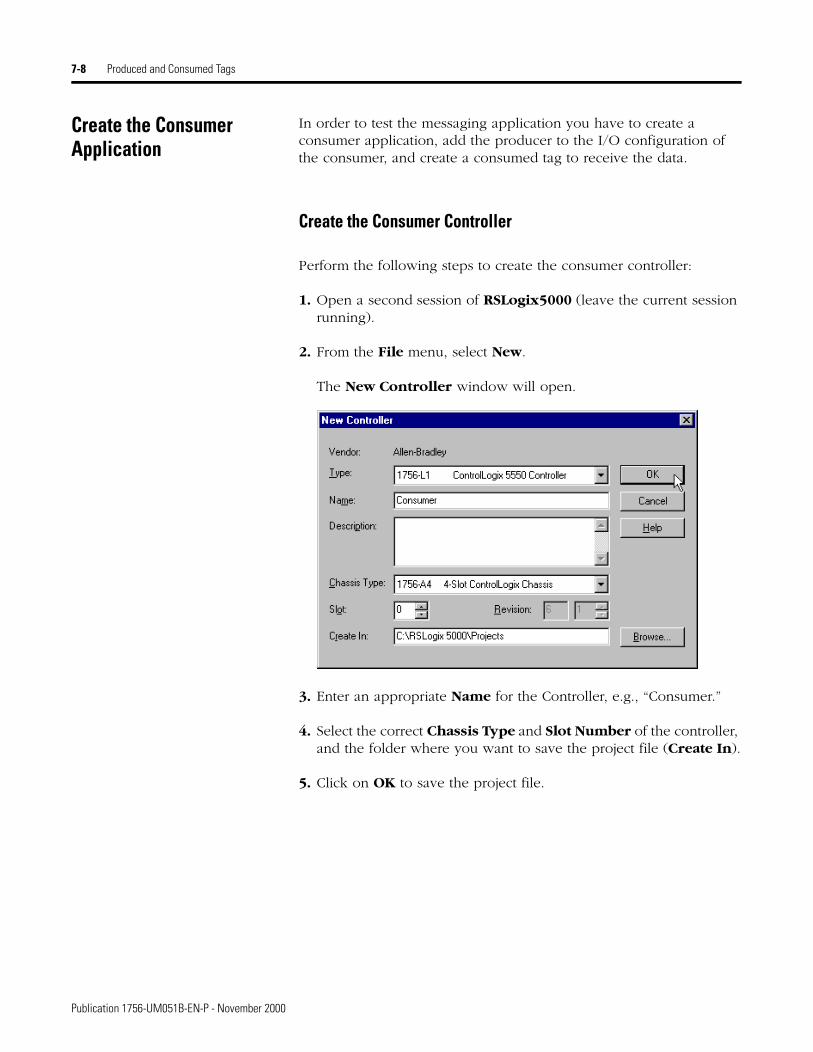
7-8 Produced and Consumed Tags
Create the Consumer Application
In order to test the messaging application you have to create a consumer application, add the producer to the I/O configuration of the consumer, and create a consumed tag to receive the data.
Create the Consumer Controller
Perform the following steps to create the consumer controller:
1. Open a second session of RSLogix5000 (leave the current session running).
2. From the File menu, select New.
The New Controller window will open.
3. Enter an appropriate Name for the Controller, e.g., “Consumer.”
4. Select the correct Chassis Type and Slot Number of the controller, and the folder where you want to save the project file (Create In).
5. Click on OK to save the project file.
Publication 1756-UM051B-EN-P - November 2000
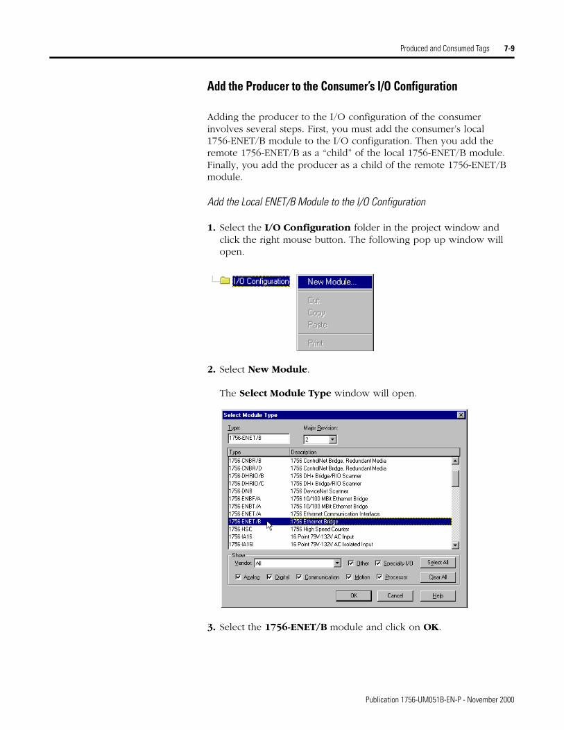
Produced and Consumed Tags 7-9
Add the Producer to the Consumer’s I/O Configuration
Adding the producer to the I/O configuration of the consumer involves several steps. First, you must add the consumer’s local 1756-ENET/B module to the I/O configuration. Then you add the remote 1756-ENET/B as a “child” of the local 1756-ENET/B module. Finally, you add the producer as a child of the remote 1756-ENET/B module.
Add the Local ENET/B Module to the I/O Configuration
1. Select the I/O Configuration folder in the project window and click the right mouse button. The following pop up window will open.
2. Select New Module.
The Select Module Type window will open.
3. Select the 1756-ENET/B module and click on OK.
Publication 1756-UM051B-EN-P - November 2000
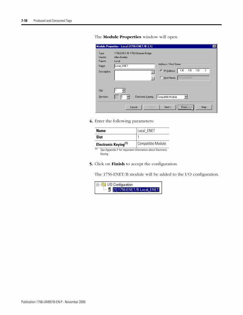
7-10 Produced and Consumed Tags
The Module Properties window will open.
4. Enter the following parameters:
5. Click on Finish to accept the configuration.
The 1756-ENET/B module will be added to the I/O configuration.
Name Local_ENET
Slot 1
Electronic Keying(1)
(1) See Appendix F for important information about Electronic Keying.
Compatible Module
Publication 1756-UM051B-EN-P - November 2000
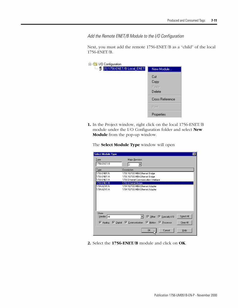
Produced and Consumed Tags 7-11
Add the Remote ENET/B Module to the I/O Configuration
Next, you must add the remote 1756-ENET/B as a “child” of the local 1756-ENET/B.
1. In the Project window, right click on the local 1756-ENET/B module under the I/O Configuration folder and select New Module from the pop-up window.
The Select Module Type window will open
2. Select the 1756-ENET/B module and click on OK.
Publication 1756-UM051B-EN-P - November 2000
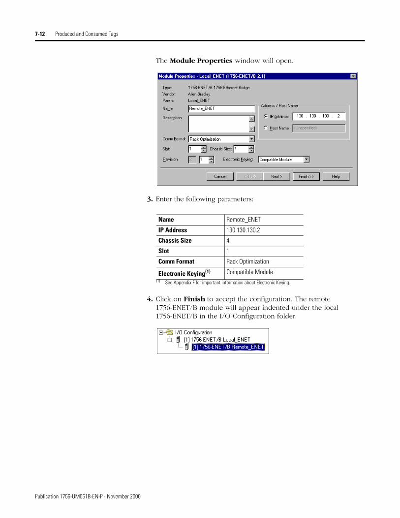
7-12 Produced and Consumed Tags
The Module Properties window will open.
3. Enter the following parameters:
4. Click on Finish to accept the configuration. The remote 1756-ENET/B module will appear indented under the local 1756-ENET/B in the I/O Configuration folder.
Name Remote_ENET
IP Address 130.130.130.2
Chassis Size 4
Slot 1
Comm Format Rack Optimization
Electronic Keying(1)
(1) See Appendix F for important information about Electronic Keying.
Compatible Module
Publication 1756-UM051B-EN-P - November 2000
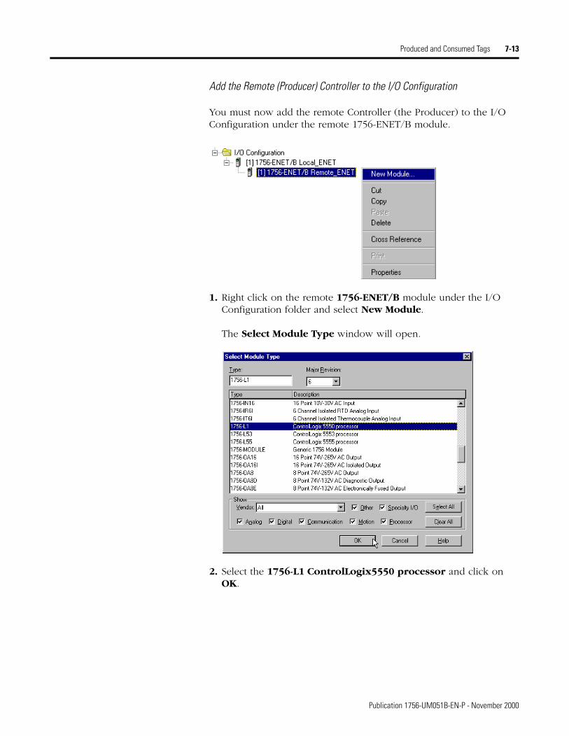
Produced and Consumed Tags 7-13
Add the Remote (Producer) Controller to the I/O Configuration
You must now add the remote Controller (the Producer) to the I/O Configuration under the remote 1756-ENET/B module.
1. Right click on the remote 1756-ENET/B module under the I/O Configuration folder and select New Module.
The Select Module Type window will open.
2. Select the 1756-L1 ControlLogix5550 processor and click on OK.
Publication 1756-UM051B-EN-P - November 2000
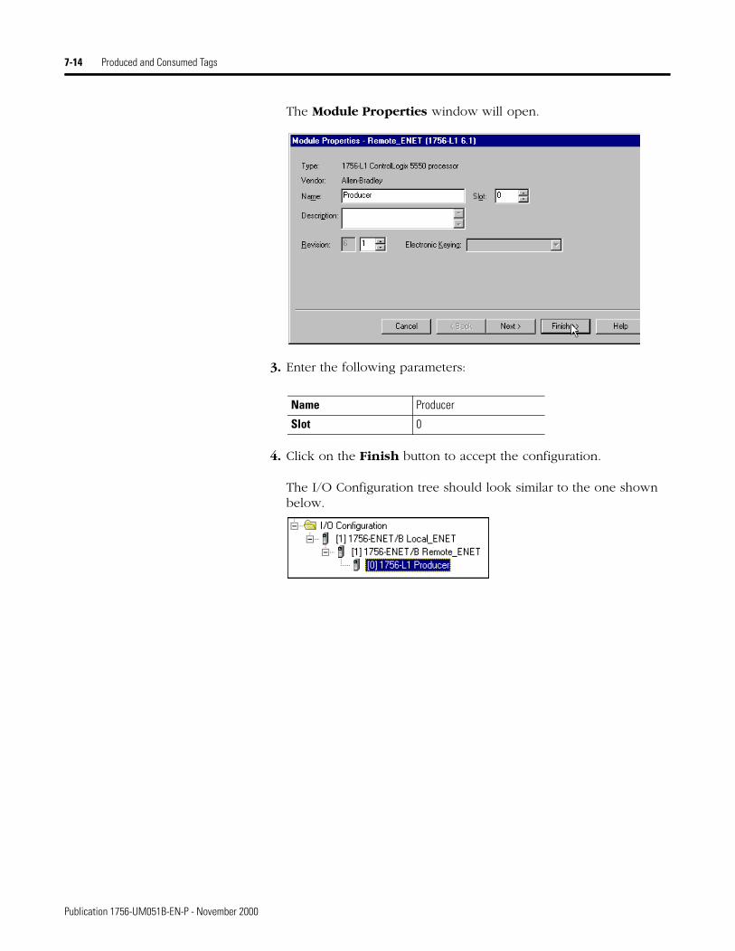
7-14 Produced and Consumed Tags
The Module Properties window will open.
3. Enter the following parameters:
4. Click on the Finish button to accept the configuration.
The I/O Configuration tree should look similar to the one shown below.
Name Producer
Slot 0
Publication 1756-UM051B-EN-P - November 2000
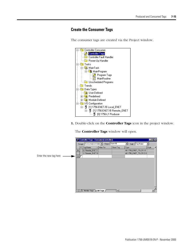
Produced and Consumed Tags 7-15
Create the Consumer Tags
The consumer tags are created via the Project window.
1. Double-click on the Controller Tags icon in the project window.
The Controller Tags window will open.
Enter the new tag here
Publication 1756-UM051B-EN-P - November 2000
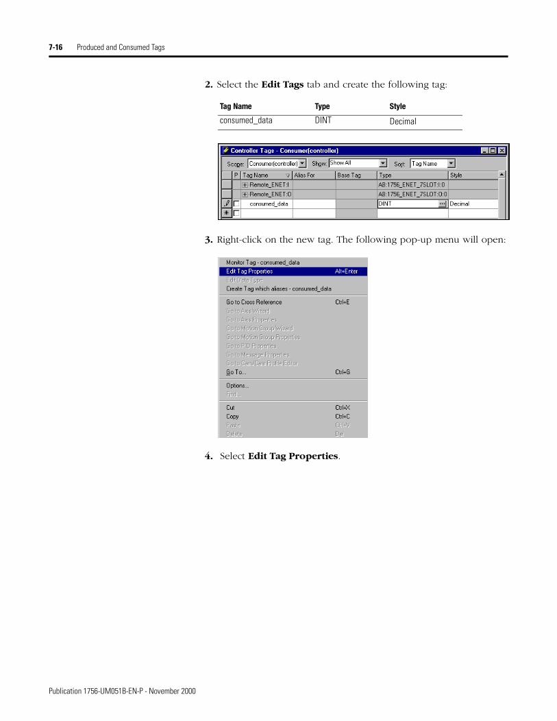
7-16 Produced and Consumed Tags
2. Select the Edit Tags tab and create the following tag:
3. Right-click on the new tag. The following pop-up menu will open:
4. Select Edit Tag Properties.
Tag Name Type Style
consumed_data DINT Decimal
Publication 1756-UM051B-EN-P - November 2000
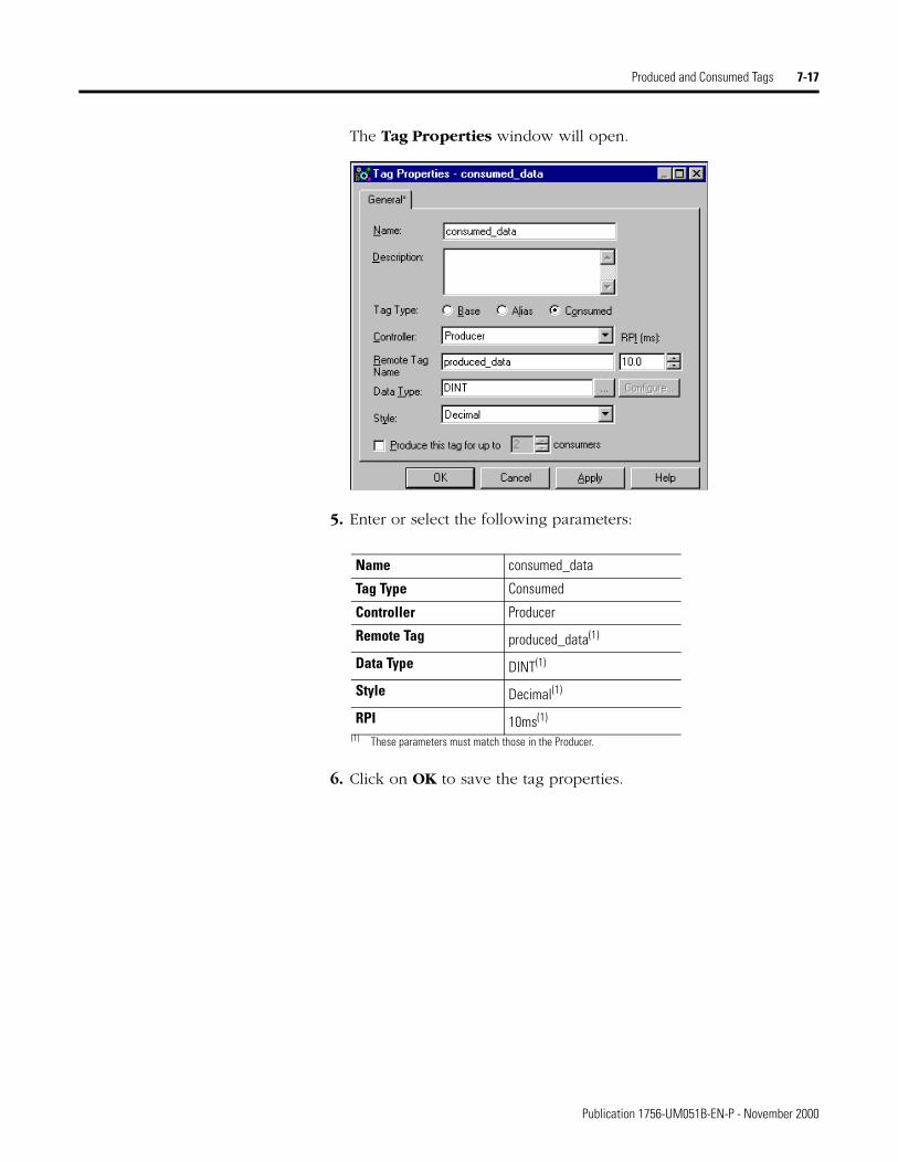
Produced and Consumed Tags 7-17
The Tag Properties window will open.
5. Enter or select the following parameters:
6. Click on OK to save the tag properties.
Name consumed_data
Tag Type Consumed
Controller Producer
Remote Tag produced_data(1)
(1) These parameters must match those in the Producer.
Data Type DINT(1)
Style Decimal(1)
RPI 10ms(1)
Publication 1756-UM051B-EN-P - November 2000
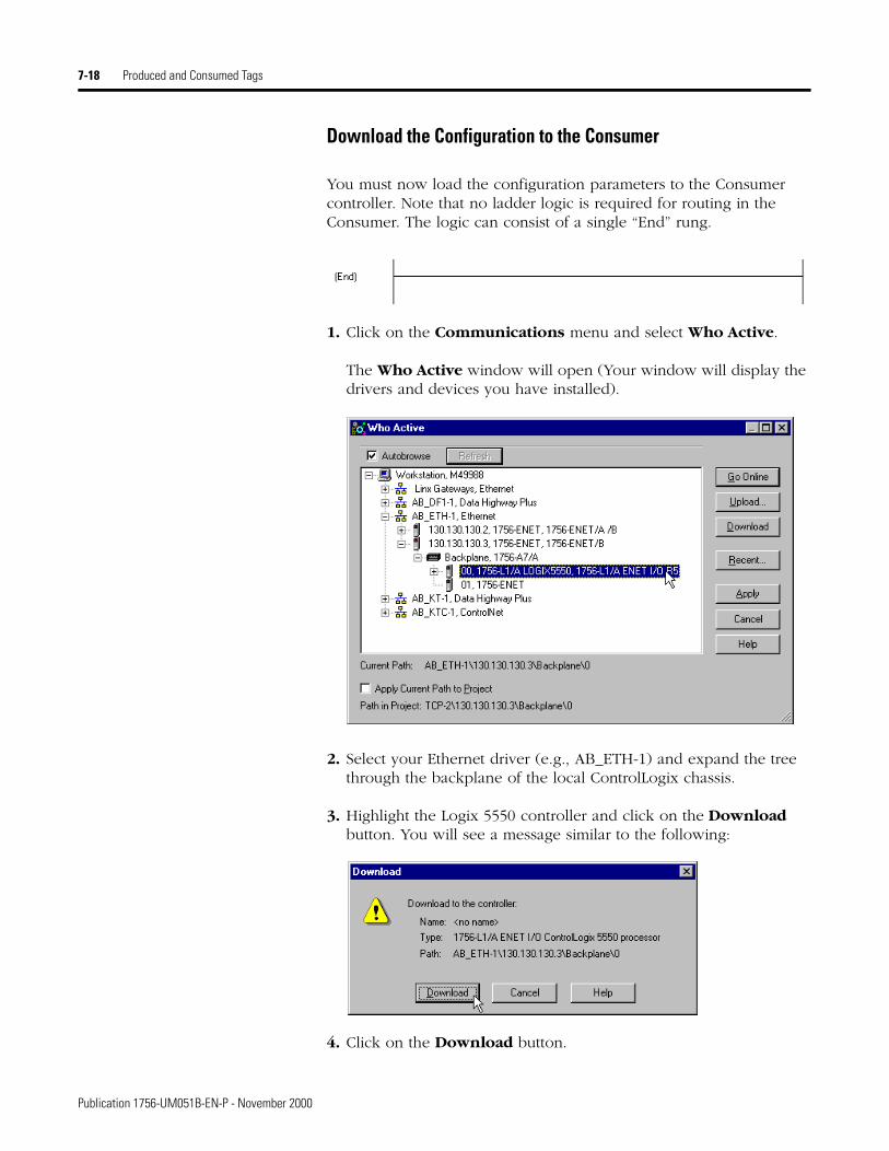
7-18 Produced and Consumed Tags
Download the Configuration to the Consumer
You must now load the configuration parameters to the Consumer controller. Note that no ladder logic is required for routing in the Consumer. The logic can consist of a single “End” rung.
1. Click on the Communications menu and select Who Active.
The Who Active window will open (Your window will display the drivers and devices you have installed).
2. Select your Ethernet driver (e.g., AB_ETH-1) and expand the tree through the backplane of the local ControlLogix chassis.
3. Highlight the Logix 5550 controller and click on the Download button. You will see a message similar to the following:
4. Click on the Download button.
Publication 1756-UM051B-EN-P - November 2000
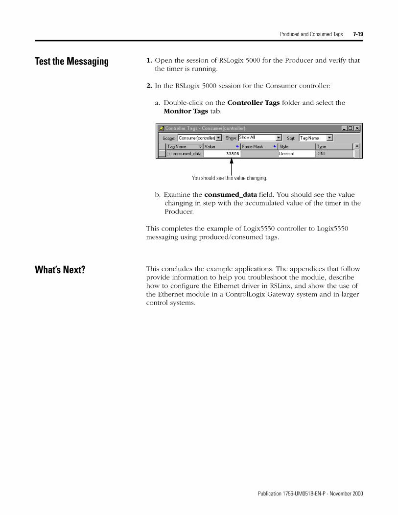
Produced and Consumed Tags 7-19
Test the Messaging 1. Open the session of RSLogix 5000 for the Producer and verify that the timer is running.
2. In the RSLogix 5000 session for the Consumer controller:
a. Double-click on the Controller Tags folder and select the Monitor Tags tab.
b. Examine the consumed_data field. You should see the value changing in step with the accumulated value of the timer in the Producer.
This completes the example of Logix5550 controller to Logix5550 messaging using produced/consumed tags.
What’s Next? This concludes the example applications. The appendices that follow provide information to help you troubleshoot the module, describe how to configure the Ethernet driver in RSLinx, and show the use of the Ethernet module in a ControlLogix Gateway system and in larger control systems.
You should see this value changing.
Publication 1756-UM051B-EN-P - November 2000

7-20 Produced and Consumed Tags
Publication 1756-UM051B-EN-P - November 2000
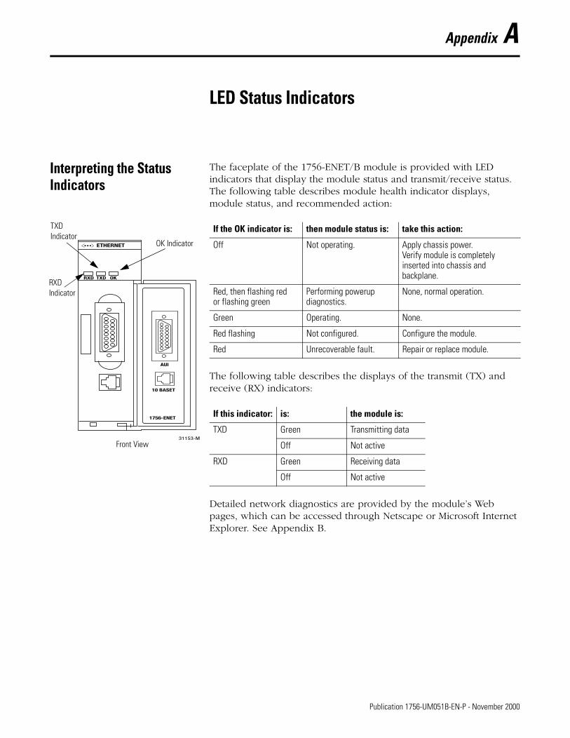
Appendix A
LED Status Indicators
Interpreting the Status Indicators
The faceplate of the 1756-ENET/B module is provided with LED indicators that display the module status and transmit/receive status. The following table describes module health indicator displays, module status, and recommended action:
The following table describes the displays of the transmit (TX) and receive (RX) indicators:
Detailed network diagnostics are provided by the module’s Web pages, which can be accessed through Netscape or Microsoft Internet Explorer. See Appendix B.
If the OK indicator is: then module status is: take this action:
Off Not operating. Apply chassis power.Verify module is completely inserted into chassis and backplane.
Red, then flashing redor flashing green
Performing powerup diagnostics.
None, normal operation.
Green Operating. None.
Red flashing Not configured. Configure the module.
Red Unrecoverable fault. Repair or replace module.
If this indicator: is: the module is:
TXD Green Transmitting data
Off Not active
RXD Green Receiving data
Off Not active
31153-M
AUI
10 BASET
1756-ENET
RXD TXD OK
ETHERNET
TXDIndicator
OK Indicator
RXDIndicator
Front View
1 Publication 1756-UM051B-EN-P - November 2000

A-2 LED Status Indicators
Publication 1756-UM051B-EN-P - November 2000
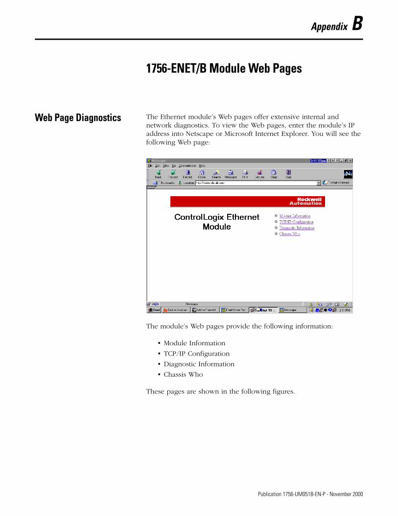
Appendix B
1756-ENET/B Module Web Pages
Web Page Diagnostics The Ethernet module’s Web pages offer extensive internal and network diagnostics. To view the Web pages, enter the module’s IP address into Netscape or Microsoft Internet Explorer. You will see the following Web page:
The module’s Web pages provide the following information:
• Module Information
• TCP/IP Configuration
• Diagnostic Information
• Chassis Who
These pages are shown in the following figures.
1 Publication 1756-UM051B-EN-P - November 2000
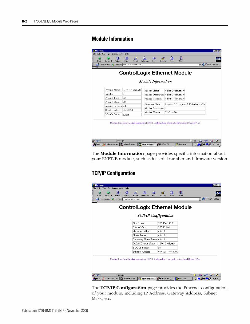
B-2 1756-ENET/B Module Web Pages
Module Information
The Module Information page provides specific information about your ENET/B module, such as its serial number and firmware version.
TCP/IP Configuration
The TCP/IP Configuration page provides the Ethernet configuration of your module, including IP Address, Gateway Address, Subnet Mask, etc.
Publication 1756-UM051B-EN-P - November 2000
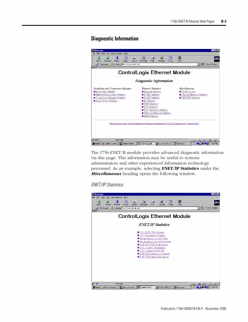
1756-ENET/B Module Web Pages B-3
Diagnostic Information
The 1756-ENET/B module provides advanced diagnostic information via this page. This information may be useful to systems administrators and other experienced information technology personnel. As an example, selecting ENET/IP Statistics under the Miscellaneous heading opens the following window.
ENET/IP Statistics
Publication 1756-UM051B-EN-P - November 2000
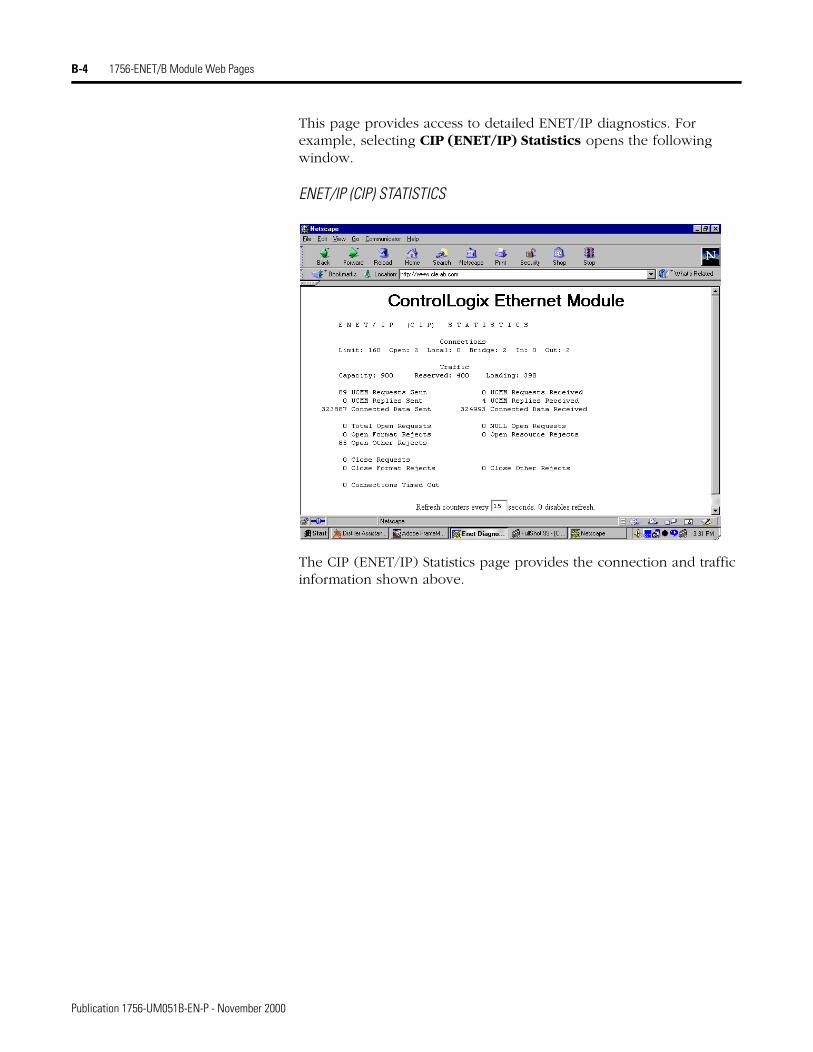
B-4 1756-ENET/B Module Web Pages
This page provides access to detailed ENET/IP diagnostics. For example, selecting CIP (ENET/IP) Statistics opens the following window.
ENET/IP (CIP) STATISTICS
The CIP (ENET/IP) Statistics page provides the connection and traffic information shown above.
Publication 1756-UM051B-EN-P - November 2000
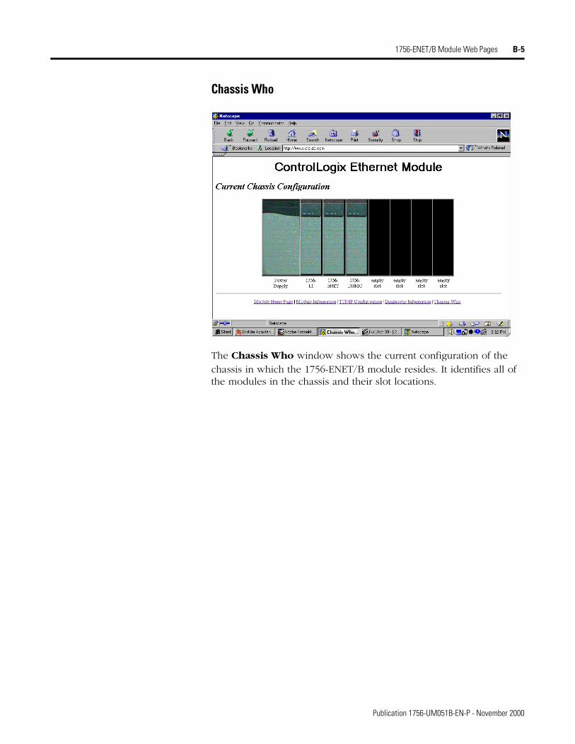
1756-ENET/B Module Web Pages B-5
Chassis Who
The Chassis Who window shows the current configuration of the chassis in which the 1756-ENET/B module resides. It identifies all of the modules in the chassis and their slot locations.
Publication 1756-UM051B-EN-P - November 2000

B-6 1756-ENET/B Module Web Pages
Publication 1756-UM051B-EN-P - November 2000
Appendix C
Configuring the RSLinx Ethernet Communication Driver
What This Appendix Contains
In order to communicate with your 1756-ENET/B modules over your network you must configure the RSLinx Ethernet communication driver (AB_ETH). You can configure the AB_ETH driver with the IP addresses of all the Ethernet modules on your system. You will need this driver to download the example application programs in this manual.
The following table lists the contents of this appendix and where to find specific information:
Installing the RSLinx Software
Use the following procedure to install RSLinx software on your computer.
1. Insert the CD in the CD-ROM drive.
Note: The CD-ROM supports Windows Autorun. Once inserted into the CD-ROM drive, if you have Autorun configured, the installation will automatically start at the first setup screen.
If Autorun is not configured for your CD-ROM drive, go to step 2.
2. From the Start menu, choose Run.
You will see the Run pop-up window.
3. Type d:/setup (if it doesn’t appear automatically), where d: is your CD-ROM driver letter.
4. Click on OK.
You will see the progress bar, followed by the welcome screen.
For information about See pageInstalling the RSLinx Software C-1
Configuring the AB_ETH Driver C-2
1 Publication 1756-UM051B-EN-P - November 2000
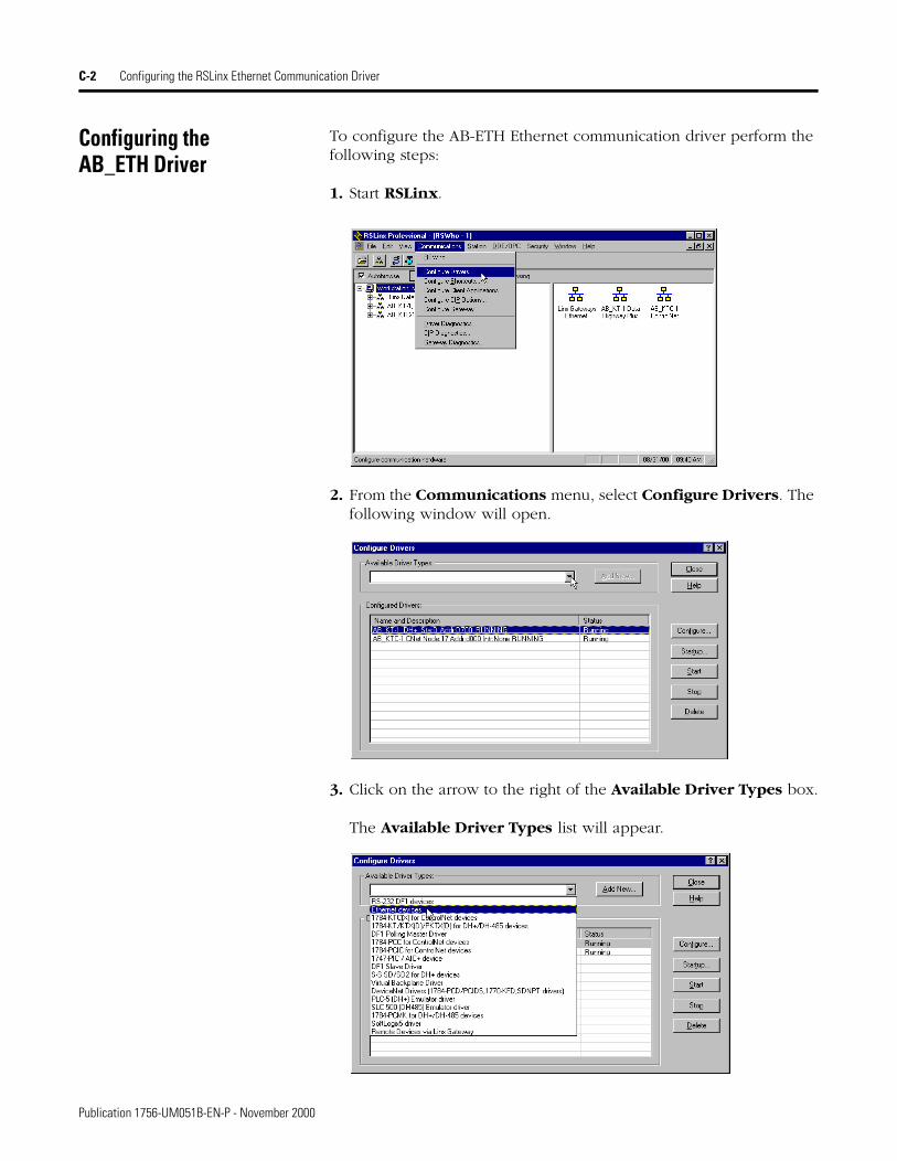
C-2 Configuring the RSLinx Ethernet Communication Driver
Configuring theAB_ETH Driver
To configure the AB-ETH Ethernet communication driver perform the following steps:
1. Start RSLinx.
2. From the Communications menu, select Configure Drivers. The following window will open.
3. Click on the arrow to the right of the Available Driver Types box.
The Available Driver Types list will appear.
Publication 1756-UM051B-EN-P - November 2000
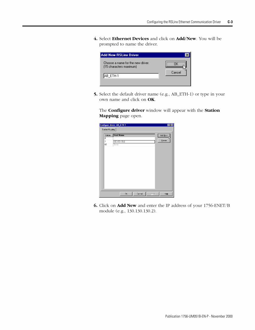
Configuring the RSLinx Ethernet Communication Driver C-3
4. Select Ethernet Devices and click on Add/New. You will be prompted to name the driver.
5. Select the default driver name (e.g., AB_ETH-1) or type in your own name and click on OK.
The Configure driver window will appear with the Station Mapping page open.
6. Click on Add New and enter the IP address of your 1756-ENET/B module (e.g., 130.130.130.2).
Publication 1756-UM051B-EN-P - November 2000
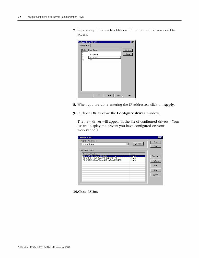
C-4 Configuring the RSLinx Ethernet Communication Driver
7. Repeat step 6 for each additional Ethernet module you need to access.
8. When you are done entering the IP addresses, click on Apply.
9. Click on OK to close the Configure driver window.
The new driver will appear in the list of configured drivers. (Your list will display the drivers you have configured on your workstation.)
10.Close RSLinx
Publication 1756-UM051B-EN-P - November 2000
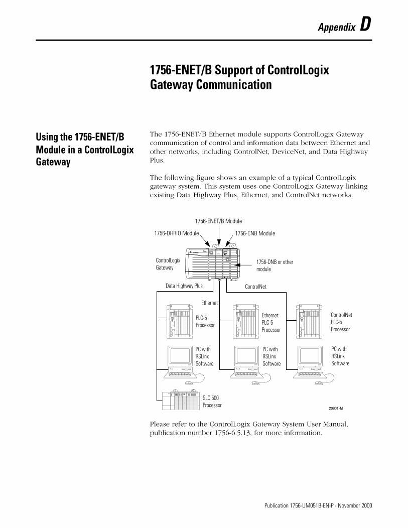
Appendix D
1756-ENET/B Support of ControlLogix Gateway Communication
Using the 1756-ENET/B Module in a ControlLogix Gateway
The 1756-ENET/B Ethernet module supports ControlLogix Gateway communication of control and information data between Ethernet and other networks, including ControlNet, DeviceNet, and Data Highway Plus.
The following figure shows an example of a typical ControlLogix gateway system. This system uses one ControlLogix Gateway linking existing Data Highway Plus, Ethernet, and ControlNet networks.
Please refer to the ControlLogix Gateway System User Manual, publication number 1756-6.5.13, for more information.
20901-M
1756-DHRIO Module
1756-ENET/B Module
1756-CNB Module
ControlLogixGateway
Data Highway Plus ControlNet
ControlNetPLC-5Processor
PC withRSLinxSoftware
EthernetPLC-5Processor
PC withRSLinxSoftware
PC withRSLinxSoftware
PLC-5Processor
Ethernet
SLC 500Processor
1756-DNB or othermodule
1 Publication 1756-UM051B-EN-P - November 2000

D-2 1756-ENET/B Support of ControlLogix Gateway Communication
Publication 1756-UM051B-EN-P - November 2000
Appendix E
Example Network Configurations
What This Appendix Contains
This appendix shows examples of Ethernet control networks, along with the RSLogix 5000 I/O configurations for those networks. You configure these networks using the procedures described in this manual, adding each remote 1756-ENET/B module and its I/O modules to the local ENET/B module in turn as you build your system.
For information about See page
Small System Example E-2
Expanded System with FLEX I/O E-3Larger Control Networks E-4
1 Publication 1756-UM051B-EN-P - November 2000
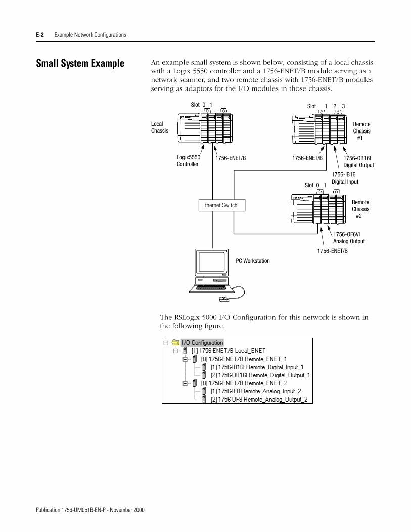
E-2 Example Network Configurations
Small System Example An example small system is shown below, consisting of a local chassis with a Logix 5550 controller and a 1756-ENET/B module serving as a network scanner, and two remote chassis with 1756-ENET/B modules serving as adaptors for the I/O modules in those chassis.
The RSLogix 5000 I/O Configuration for this network is shown in the following figure.
Logix5550 1756-ENET/B 1756-ENET/B
LocalChassis
RemoteChassis
PC Workstation
Slot 0 1 Slot 1 2 3
1756-IB16Digital Input
1756-OB16IDigital OutputController
#1
RemoteChassis
#2
1756-ENET/B
1756-OF6VIAnalog Output
Slot 0 1
Ethernet Switch
Publication 1756-UM051B-EN-P - November 2000
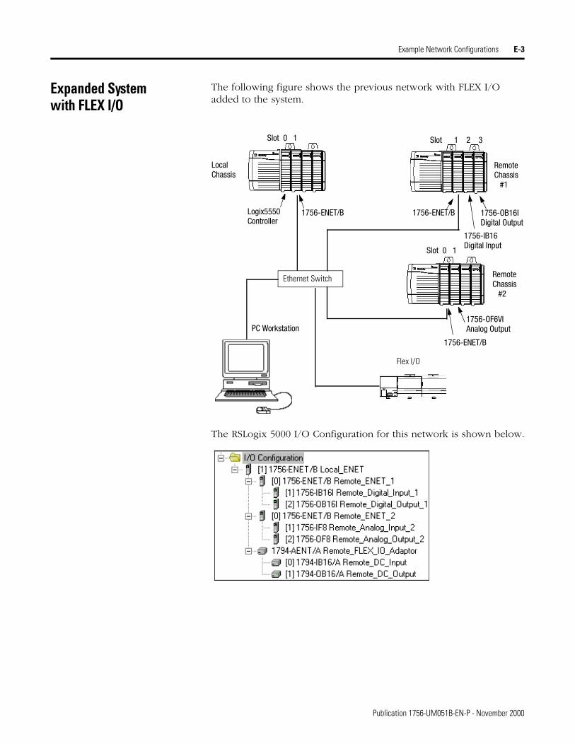
Example Network Configurations E-3
Expanded Systemwith FLEX I/O
The following figure shows the previous network with FLEX I/O added to the system.
The RSLogix 5000 I/O Configuration for this network is shown below.
Logix5550 1756-ENET/B 1756-ENET/B
LocalChassis
RemoteChassis
PC Workstation
Slot 0 1 Slot 1 2 3
1756-IB16Digital Input
1756-OB16IDigital OutputController
#1
RemoteChassis
#2
1756-ENET/B
1756-OF6VIAnalog Output
Slot 0 1
Ethernet Switch
Flex I/O
Publication 1756-UM051B-EN-P - November 2000
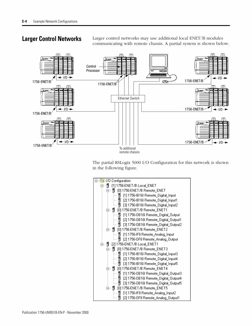
E-4 Example Network Configurations
Larger Control Networks Larger control networks may use additional local ENET/B modules communicating with remote chassis. A partial system is shown below.
The partial RSLogix 5000 I/O Configuration for this network is shown in the following figure.
.
Ethernet Switch
To addtionalremote chassis
1756-ENET/B
1756-ENET/B
1756-ENET/B
1756-ENET/B1756-ENET/B
ControlProcessor
I/O
I/O
I/O
I/O
I/O1756-ENET/B
1756-ENET/B I/O
Publication 1756-UM051B-EN-P - November 2000
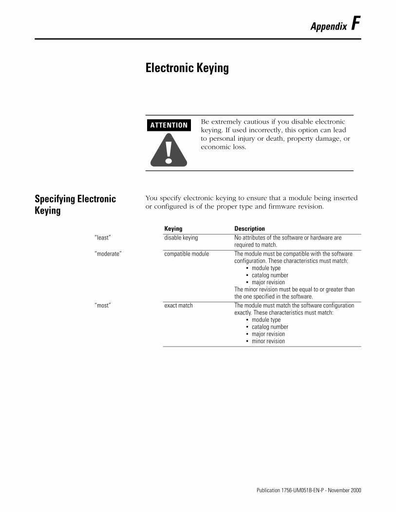
Appendix F
Electronic Keying
Specifying Electronic Keying
You specify electronic keying to ensure that a module being inserted or configured is of the proper type and firmware revision.
ATTENTION
!Be extremely cautious if you disable electronic keying. If used incorrectly, this option can lead to personal injury or death, property damage, or economic loss.
Keying Description“least” disable keying No attributes of the software or hardware are
required to match.“moderate” compatible module The module must be compatible with the software
configuration. These characteristics must match:• module type• catalog number• major revision
The minor revision must be equal to or greater than the one specified in the software.
“most” exact match The module must match the software configuration exactly. These characteristics must match:
• module type• catalog number• major revision• minor revision
1 Publication 1756-UM051B-EN-P - November 2000

F-2 Electronic Keying
Publication 1756-UM051B-EN-P - November 2000
Index
Aabout the 1756-ENET/B module 1-1 to 1-5
control and information protocol (CIP) 1-4mixing rack optimized and direct connections 1-3module features 1-1producer/consumer model 1-4rack optimized and direct connections 1-2 to 1-3requested packet interval (RPI) 1-5what the module does 1-2
about this user manual P-1 to P-8analog I/O with direct connection 6-1 to 6-12
add I/O module to configuration 6-4 to 6-7create the example application 6-3 to 6-11download program 6-11edit controller tags 6-8 to 6-9modify ladder program 6-10set up the hardware 6-2test example application 6-12
Bbefore you configure your module 3-1 to 3-6BootP
using a BootP server 4-5 to 4-6
Ccommon techniques used in this manual P-2configuration requirements 3-3 to 3-5
gateway address 3-4IP address 3-3 to 3-4subnet mask 3-5
configuring Ethernet communication drivers C-1 to C-4
AB_ETH driver C-2 to C-4installing the software C-1
configuring the Ethernet module 4-1 to 4-7using a BootP server 4-5 to 4-6using DHCP software 4-7using RSLinx software 4-2 to 4-4using the Rockwell BootP utility 4-1
consumed tags 1-4control and information protocol (CIP) 1-4controller tags
create consumer tags 7-15 to 7-17create producer tags 7-4 to 7-5editing 5-12 to 5-13, 6-8 to 6-9
ControlLogix gateway communication1756-ENET/B support D-1using the 1756-ENET/B D-1
DDCHP software
using to configure the Ethernet module 4-7diagnostics
chassis who B-5diagnostic information B-3 to B-4module information B-2TCP/IP configuration B-2web pages B-1 to B-5
direct connectionsee analog I/O with direct connection
Eelectronic keying F-1Ethernet protocols 3-1 to 3-2
EtherNet/IP 3-2SNMP 3-2TCP/IP 3-1UDP 3-2
EtherNet/IP 3-2example applications
about the example applications P-3system components P-4
example network configurations E-1 to E-4expanded system with FLEX I/O E-3larger control networks E-4small system example E-2
Ffinding more information P-5
Ggateways 3-4
Hhow to use this manual P-2 to P-4
II/O configuration
analog I/O 6-4 to 6-7digital I/O 5-8 to 5-12local ENET module 5-4 to 5-5local ENET module in consumer 7-9 to 7-10producer in consumer’s I/O configuration 7-13 to 7-14remote ENET module 5-6 to 5-8remote ENET module in consumer 7-11 to 7-12
Publication 1756-UM051B-EN-P - November 2000
2 Index
installing the ethernet module 2-1 to 2-8applying chassis power 2-7checking power supply and module status 2-8connecting to the ethernet network 2-6determining module slot location 2-3inserting module in the chassis 2-4insertion and removal under power 2-2preparing the chassis 2-2removing or replacing the module 2-5wiring the ethernet connector 2-6
IP address 3-3 to 3-4
Lladder program 5-14 to 5-15, 6-10 to 6-11, 7-6 to 7-7LED status indicators A-1
Mmodule features 1-1
Pproduced and consumed tags 7-1 to 7-19
create consumer application 7-8 to 7-18add producer to consumer’s I/O configuration 7-9 to
7-14create consumer controller 7-8create consumer tags 7-15 to 7-17download configuration to consumer 7-18
create producer application 7-3 to 7-7create producer ladder program 7-6create producer tags 7-4 to 7-5download producer application program 7-7
set up the hardware 7-2test the messaging 7-19
produced tags 1-4producer/consumer model 1-4
Rrack optimized and direct connections 1-2 to 1-3
mixing rack optimized and direct connections 1-3rack optimized I/O 5-1 to 5-17
add local ENET module to I/O configuration 5-4 to 5-5add remote ENET module to I/O configuration 5-6 to 5-8add remote I/O modules to I/O configuration 5-8 to
5-12create example application 5-3 to 5-15create ladder program 5-14download program to controller 5-15edit controller tags 5-12 to 5-13set up the hardware 5-2test example application 5-16 to 5-17
related publications P-5requested packet interval (RPI) 1-5Rockwell BootP utility 4-1RSLinx
using to configure the Ethernet module 4-2 to 4-4RSLinx communication drivers C-1 to C-4
AB_ETH driver C-2 to C-4installing the software C-1
Ssimple network management protocol (SNMP) 3-2status indicators A-1subnet mask 3-5
TTCP/IP (transmission control protocol/internet
protocol) 3-1terminology P-6 to P-8
UUDP (user datagram protocol) 3-2
Wweb pages B-1 to B-5
chassis who B-5diagnostic information B-3 to B-4module information B-2TCP/IP configuration B-2
what the module does 1-2who should use this manual P-1
Publication 1756-UM051B-EN-P - November 2000

Allen-BradleyPublication Problem Report
Pub. Name ControlLogix Ethernet Communication Interface Module User Manual
Cat. No. 1756-ENET/B Pub. No. 1756-UM051B-EN-P Pub. Date November 2000 Part No. 957400-29
Check Problem(s) Type: Describe Problem(s) Internal Use Only
Technical Accuracy text illustration
Completeness procedure/step illustration definition info in manual
What information is missing? example guideline feature (accessibility)
explanation other info not in
Clarity
What is unclear?
Sequence
What is not in the right order?
Other Comments
Use back for more comments.
Your Name Location/Phone
Return to: Marketing Communications, Allen-Bradley., 1 Allen-Bradley Drive, Mayfield Hts., OH 44124-6118Phone: (440) 646-3176FAX: (440) 646-4320
Publication 1756-UM051B-EN-P- November 2000 957400-29

Other Comments
PLEASE FOLD HERE
BUSINESS REPLY MAILFIRST-CLASS MAIL PERMIT NO. 18235 CLEVELAND OH
POSTAGE WILL BE PAID BY THE ADDRESSEE
1 ALLEN BRADLEY DRMAYFIELD HEIGHTS OH 44124-9705
( )


Publication 1756-UM051B-EN-P - November 2000 2 PN 957400-29Supersedes Publication 1756-UM051A-EN-P - August 1997 © 2000 Rockwell International Corporation. Printed in the U.S.A.
Back Cover