Embed Size (px)
Citation preview
Technological University Dublin Technological University Dublin
ARROW@TU Dublin ARROW@TU Dublin
Articles Engineering: Education and Innovation
2015-07-13
Thermal Energy Storage in Building Integrated Thermal Systems: Thermal Energy Storage in Building Integrated Thermal Systems:
A Review. Part 2. Integration as Passive System A Review. Part 2. Integration as Passive System
Dervilla Niall Technological University Dublin, [email protected]
Sarah McCormack Trinity College Dublin, [email protected]
Philip Griffiths University of Ulster
See next page for additional authors
Follow this and additional works at: https://arrow.tudublin.ie/engineducart
Part of the Architectural Engineering Commons, Civil Engineering Commons, Other Engineering
Commons, and the Structural Engineering Commons
Recommended Citation Recommended Citation Niall, D. et al. (2015) Thermal Energy Storage in Building Integrated Thermal Systems: A Review. Part 2. Integration as Passive System, Journal Renewable Energy, vol. 85, January 2016 pp. 1334-1356. doi:10.1016/j.renene.2015.06.064
This Article is brought to you for free and open access by the Engineering: Education and Innovation at ARROW@TU Dublin. It has been accepted for inclusion in Articles by an authorized administrator of ARROW@TU Dublin. For more information, please contact [email protected], [email protected].
This work is licensed under a Creative Commons Attribution-Noncommercial-Share Alike 4.0 License

Authors Authors Dervilla Niall, Sarah McCormack, Philip Griffiths, Luisa Cabeza, Lidia Navarro, Albert Castell, Alvaro de Grazia, and Maria Brown
This article is available at ARROW@TU Dublin: https://arrow.tudublin.ie/engineducart/4

AuthorsDervilla P. Niall CEng, Sarah McCormack Dr, Philip Griffiths Dr, Luisa F. Cabeza Dr, Lidia Navarro, AlbertCastell, Alvaro de Grazia, and Maria Brown
Review
Thermal energy storage in building integrated thermal systems: Areview. Part 2. Integration as passive system
Lidia Navarro a, Alvaro de Gracia b, Dervilla Niall c, Albert Castell a, Maria Browne c,Sarah J. McCormack c, Philip Griffiths d, Luisa F. Cabeza a, *
a GREA Innovaci�o Concurrent, Universitat de Lleida, Edifici CREA, Pere de Cabrera s/n, 25001 Lleida, Spainb CELIMIN, Universidad de Antofagasta, Av. Universidad de Antofagasta 02800, Antofagasta, Chilec Department of Civil, Structural and Environmental Engineering, University of Dublin, Trinity College, Dublin, Irelandd Centre for Sustainable Technologies, University of Ulster at Jordanstown, Newtownabbey, Co. Antrim BT38 9QB, UK
a r t i c l e i n f o
Article history:Received 19 February 2015Received in revised form10 June 2015Accepted 26 June 2015Available online xxx
Keywords:Thermal energy storagePassive systemBuilding integratedSensible heat storageLatent heat storage
a b s t r a c t
Energy consumption trends in residential and commercial buildings show a significant increase in recentdecades. One of the key points for reducing energy consumption in buildings is to decrease the energydemand. Buildings envelopes are not just a structure they also provide protection from outdoor weatherconditions always taking into account the local climate. Thermal energy storage has been used andapplied to the building structure by taking advantage of sensible heat storage of materials with highthermal mass. But in recent years, researchers have focused their studies on the implementation of latentheat storage materials that if well incorporated could have high potential in energy demand reductionwithout occupying the space required by sensible storage. The aim of this study is to review the thermalenergy storage passive systems that have been integrated in building components such as walls, ceilingsor floors, and to classify them depending on their component integration.
© 2015 Elsevier Ltd. All rights reserved.
1. Introduction
Buildings use 32% of global final energy demand, and generate30% of energy-related CO2 emissions, and approximately one-thirdof the black carbon emissions [1]. Over 60% of residential andalmost 50% of commercial buildings use thermal energy, withhigher contribution fromwater heating in residential buildings andfrom cooling in commercial ones.
The drivers of the heating and cooling energy demand inbuildings were identified by ÜrgeeVorsatz et al. [1] such as;number of households, persons per household, floor space percapita, and specific energy consumption; and for commercialbuildings are GDP (gross domestic product), floor space per GDP,and specific energy consumption.
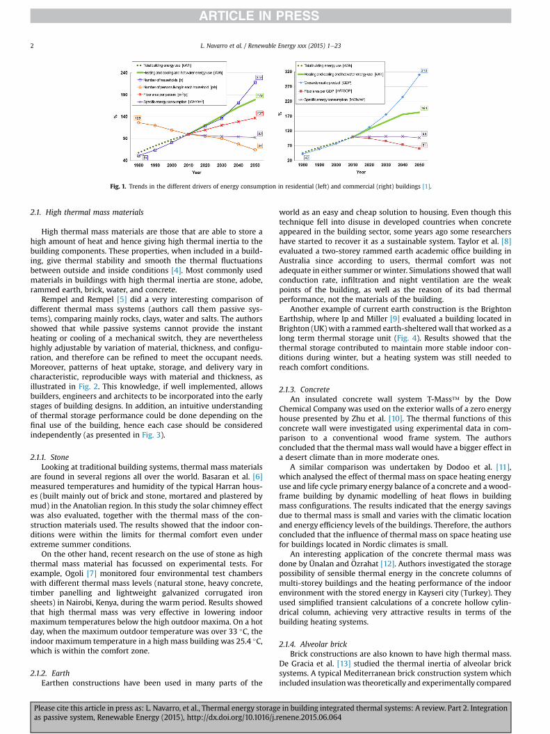
The trends in Fig. 1 show that decreasing the energy demand ofbuildings is a necessity. As shown in Part 1 of this review [2], TES(Thermal energy storage) is one of the highlighted technologies toachieve this aim, and its integration in buildings is of much interest,
to achieve a better final user acceptance of the technology.This part of the review presents building integrated passive
thermal storage systems. As commented in Part 1 [2], althoughbuilding integration is not mentioned in the publications classifiedhere, these systems are integrated in the building per se, since theyare included in the building core (usually in the walls, ceiling orfloor). Active TES systems are presented in Part 1.
Of the three thermal energy storage methods existing, onlysensible heat storage and latent heat storage are used in passivebuilding systems. Thermochemical energy storage always usesactive systems. The following section provides the classification ofthe storage methods.
2. Sensible heat storage
Sensible heat storage is the most common thermal storagemethod which has been used in several applications with water,stone, or brick as the storage material. The method consists oftransferring heat to the storage medium that will increase itstemperature and store that heat [3]. The potential of this methodmainly depends on the heat capacity of the storage material, themass and the thermal gradient to which the storage is exposed.
* Corresponding author.E-mail address: [email protected] (L.F. Cabeza).
Contents lists available at ScienceDirect
Renewable Energy
journal homepage: www.elsevier .com/locate/renene
http://dx.doi.org/10.1016/j.renene.2015.06.0640960-1481/© 2015 Elsevier Ltd. All rights reserved.
Renewable Energy xxx (2015) 1e23
Please cite this article in press as: L. Navarro, et al., Thermal energy storage in building integrated thermal systems: A review. Part 2. Integrationas passive system, Renewable Energy (2015), http://dx.doi.org/10.1016/j.renene.2015.06.064
2.1. High thermal mass materials
High thermal mass materials are those that are able to store ahigh amount of heat and hence giving high thermal inertia to thebuilding components. These properties, when included in a build-ing, give thermal stability and smooth the thermal fluctuationsbetween outside and inside conditions [4]. Most commonly usedmaterials in buildings with high thermal inertia are stone, adobe,rammed earth, brick, water, and concrete.
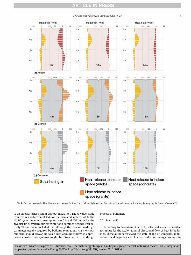
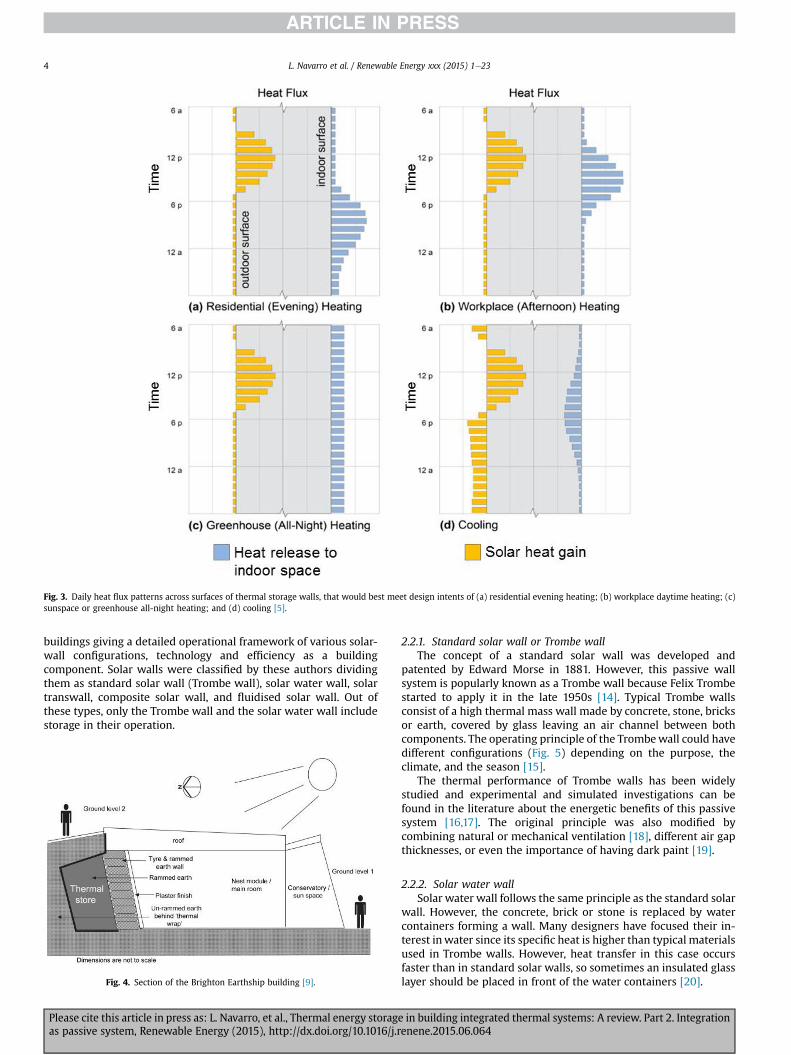
Rempel and Rempel [5] did a very interesting comparison ofdifferent thermal mass systems (authors call them passive sys-tems), comparing mainly rocks, clays, water and salts. The authorsshowed that while passive systems cannot provide the instantheating or cooling of a mechanical switch, they are neverthelesshighly adjustable by variation of material, thickness, and configu-ration, and therefore can be refined to meet the occupant needs.Moreover, patterns of heat uptake, storage, and delivery vary incharacteristic, reproducible ways with material and thickness, asillustrated in Fig. 2. This knowledge, if well implemented, allowsbuilders, engineers and architects to be incorporated into the earlystages of building designs. In addition, an intuitive understandingof thermal storage performance could be done depending on thefinal use of the building, hence each case should be consideredindependently (as presented in Fig. 3).
2.1.1. StoneLooking at traditional building systems, thermal mass materials
are found in several regions all over the world. Basaran et al. [6]measured temperatures and humidity of the typical Harran hous-es (built mainly out of brick and stone, mortared and plastered bymud) in the Anatolian region. In this study the solar chimney effectwas also evaluated, together with the thermal mass of the con-struction materials used. The results showed that the indoor con-ditions were within the limits for thermal comfort even underextreme summer conditions.
On the other hand, recent research on the use of stone as highthermal mass material has focussed on experimental tests. Forexample, Ogoli [7] monitored four environmental test chamberswith different thermal mass levels (natural stone, heavy concrete,timber panelling and lightweight galvanized corrugated ironsheets) in Nairobi, Kenya, during the warm period. Results showedthat high thermal mass was very effective in lowering indoormaximum temperatures below the high outdoor maxima. On a hotday, when the maximum outdoor temperature was over 33 �C, theindoor maximum temperature in a high mass building was 25.4 �C,which is within the comfort zone.
2.1.2. EarthEarthen constructions have been used in many parts of the
world as an easy and cheap solution to housing. Even though thistechnique fell into disuse in developed countries when concreteappeared in the building sector, some years ago some researchershave started to recover it as a sustainable system. Taylor et al. [8]evaluated a two-storey rammed earth academic office building inAustralia since according to users, thermal comfort was notadequate in either summer or winter. Simulations showed that wallconduction rate, infiltration and night ventilation are the weakpoints of the building, as well as the reason of its bad thermalperformance, not the materials of the building.
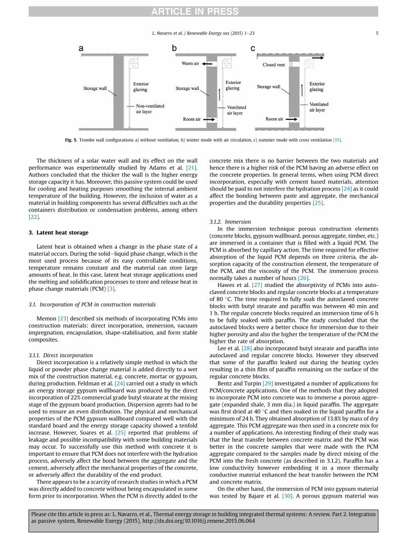
Another example of current earth construction is the BrightonEarthship, where Ip and Miller [9] evaluated a building located inBrighton (UK) with a rammed earth-shelteredwall that worked as along term thermal storage unit (Fig. 4). Results showed that thethermal storage contributed to maintain more stable indoor con-ditions during winter, but a heating system was still needed toreach comfort conditions.
2.1.3. ConcreteAn insulated concrete wall system T-Mass™ by the Dow
Chemical Company was used on the exterior walls of a zero energyhouse presented by Zhu et al. [10]. The thermal functions of thisconcrete wall were investigated using experimental data in com-parison to a conventional wood frame system. The authorsconcluded that the thermal mass wall would have a bigger effect ina desert climate than in more moderate ones.
A similar comparison was undertaken by Dodoo et al. [11],which analysed the effect of thermal mass on space heating energyuse and life cycle primary energy balance of a concrete and awood-frame building by dynamic modelling of heat flows in buildingmass configurations. The results indicated that the energy savingsdue to thermal mass is small and varies with the climatic locationand energy efficiency levels of the buildings. Therefore, the authorsconcluded that the influence of thermal mass on space heating usefor buildings located in Nordic climates is small.
An interesting application of the concrete thermal mass wasdone by Ünalan and €Ozrahat [12]. Authors investigated the storagepossibility of sensible thermal energy in the concrete columns ofmulti-storey buildings and the heating performance of the indoorenvironment with the stored energy in Kayseri city (Turkey). Theyused simplified transient calculations of a concrete hollow cylin-drical column, achieving very attractive results in terms of thebuilding heating systems.
2.1.4. Alveolar brickBrick constructions are also known to have high thermal mass.
De Gracia et al. [13] studied the thermal inertia of alveolar bricksystems. A typical Mediterranean brick construction system whichincluded insulationwas theoretically and experimentally compared
Fig. 1. Trends in the different drivers of energy consumption in residential (left) and commercial (right) buildings [1].
L. Navarro et al. / Renewable Energy xxx (2015) 1e232
Please cite this article in press as: L. Navarro, et al., Thermal energy storage in building integrated thermal systems: A review. Part 2. Integrationas passive system, Renewable Energy (2015), http://dx.doi.org/10.1016/j.renene.2015.06.064
to an alveolar brick system without insulation. The U-value studyresulted in a reduction of 45% for the insulated system, while theHVAC system energy consumption was 2% and 13% more for thealveolar brick system during winter and summer periods, respec-tively. The authors concluded that, although the U-value is a designparameter usually required by building regulations, transient pa-rameters should always be taken into account otherwise appro-priate construction systems might be discarded in the design
process of buildings.
2.2. Solar walls
According to Saadatian et al. [14] solar walls offer a feasibletechnique for the exploitation of directional flow of heat in build-ings. These authors reviewed the state-of-the-art concepts, appli-cations and significance of solar walls for energy savings in
Fig. 2. Exterior mass walls. Heat fluxes across outdoor (left axis) and indoor (right axis) surfaces of exterior walls on a typical sunny January day in Denver, Colorado [5].
L. Navarro et al. / Renewable Energy xxx (2015) 1e23 3
Please cite this article in press as: L. Navarro, et al., Thermal energy storage in building integrated thermal systems: A review. Part 2. Integrationas passive system, Renewable Energy (2015), http://dx.doi.org/10.1016/j.renene.2015.06.064
buildings giving a detailed operational framework of various solar-wall configurations, technology and efficiency as a buildingcomponent. Solar walls were classified by these authors dividingthem as standard solar wall (Trombe wall), solar water wall, solartranswall, composite solar wall, and fluidised solar wall. Out ofthese types, only the Trombe wall and the solar water wall includestorage in their operation.
2.2.1. Standard solar wall or Trombe wallThe concept of a standard solar wall was developed and
patented by Edward Morse in 1881. However, this passive wallsystem is popularly known as a Trombe wall because Felix Trombestarted to apply it in the late 1950s [14]. Typical Trombe wallsconsist of a high thermal mass wall made by concrete, stone, bricksor earth, covered by glass leaving an air channel between bothcomponents. The operating principle of the Trombewall could havedifferent configurations (Fig. 5) depending on the purpose, theclimate, and the season [15].
The thermal performance of Trombe walls has been widelystudied and experimental and simulated investigations can befound in the literature about the energetic benefits of this passivesystem [16,17]. The original principle was also modified bycombining natural or mechanical ventilation [18], different air gapthicknesses, or even the importance of having dark paint [19].
2.2.2. Solar water wallSolar water wall follows the same principle as the standard solar
wall. However, the concrete, brick or stone is replaced by watercontainers forming a wall. Many designers have focused their in-terest inwater since its specific heat is higher than typical materialsused in Trombe walls. However, heat transfer in this case occursfaster than in standard solar walls, so sometimes an insulated glasslayer should be placed in front of the water containers [20].
Fig. 3. Daily heat flux patterns across surfaces of thermal storage walls, that would best meet design intents of (a) residential evening heating; (b) workplace daytime heating; (c)sunspace or greenhouse all-night heating; and (d) cooling [5].
Fig. 4. Section of the Brighton Earthship building [9].
L. Navarro et al. / Renewable Energy xxx (2015) 1e234
Please cite this article in press as: L. Navarro, et al., Thermal energy storage in building integrated thermal systems: A review. Part 2. Integrationas passive system, Renewable Energy (2015), http://dx.doi.org/10.1016/j.renene.2015.06.064
The thickness of a solar water wall and its effect on the wallperformance was experimentally studied by Adams et al. [21].Authors concluded that the thicker the wall is the higher energystorage capacity it has. Moreover, this passive system could be usedfor cooling and heating purposes smoothing the internal ambienttemperature of the building. However, the inclusion of water as amaterial in building components has several difficulties such as thecontainers distribution or condensation problems, among others[22].
3. Latent heat storage
Latent heat is obtained when a change in the phase state of amaterial occurs. During the solideliquid phase change, which is themost used process because of its easy controllable conditions,temperature remains constant and the material can store largeamounts of heat. In this case, latent heat storage applications usedthe melting and solidification processes to store and release heat inphase change materials (PCM) [3].
3.1. Incorporation of PCM in construction materials
Memon [23] described six methods of incorporating PCMs intoconstruction materials: direct incorporation, immersion, vacuumimpregnation, encapsulation, shape-stabilisation, and form stablecomposites.
3.1.1. Direct incorporationDirect incorporation is a relatively simple method in which the
liquid or powder phase change material is added directly to a wetmix of the construction material, e.g. concrete, mortar or gypsum,during production. Feldman et al. [24] carried out a study in whichan energy storage gypsum wallboard was produced by the directincorporation of 22% commercial grade butyl stearate at the mixingstage of the gypsum board production. Dispersion agents had to beused to ensure an even distribution. The physical and mechanicalproperties of the PCM gypsum wallboard compared well with thestandard board and the energy storage capacity showed a tenfoldincrease. However, Soares et al. [25] reported that problems ofleakage and possible incompatibility with some building materialsmay occur. To successfully use this method with concrete it isimportant to ensure that PCM does not interferewith the hydrationprocess, adversely affect the bond between the aggregate and thecement, adversely affect the mechanical properties of the concrete,or adversely affect the durability of the end product.
There appears to be a scarcity of research studies inwhich a PCMwas directly added to concrete without being encapsulated in someform prior to incorporation. When the PCM is directly added to the
concrete mix there is no barrier between the two materials andhence there is a higher risk of the PCM having an adverse effect onthe concrete properties. In general terms, when using PCM directincorporation, especially with cement based materials, attentionshould be paid to not interfere the hydration process [24] as it couldaffect the bonding between paste and aggregate, the mechanicalproperties and the durability properties [25].
3.1.2. ImmersionIn the immersion technique porous construction elements
(concrete blocks, gypsumwallboard, porous aggregate, timber, etc.)are immersed in a container that is filled with a liquid PCM. ThePCM is absorbed by capillary action. The time required for effectiveabsorption of the liquid PCM depends on three criteria, the ab-sorption capacity of the construction element, the temperature ofthe PCM, and the viscosity of the PCM. The immersion processnormally takes a number of hours [26].
Hawes et al. [27] studied the absorptivity of PCMs into auto-claved concrete blocks and regular concrete blocks at a temperatureof 80 �C. The time required to fully soak the autoclaved concreteblocks with butyl stearate and paraffin was between 40 min and1 h. The regular concrete blocks required an immersion time of 6 hto be fully soaked with paraffin. The study concluded that theautoclaved blocks were a better choice for immersion due to theirhigher porosity and also the higher the temperature of the PCM thehigher the rate of absorption.
Lee et al. [28] also incorporated butyl stearate and paraffin intoautoclaved and regular concrete blocks. However they observedthat some of the paraffin leaked out during the heating cyclesresulting in a thin film of paraffin remaining on the surface of theregular concrete blocks.
Bentz and Turpin [29] investigated a number of applications forPCM/concrete applications. One of the methods that they adoptedto incorporate PCM into concrete was to immerse a porous aggre-gate (expanded shale, 3 mm dia.) in liquid paraffin. The aggregatewas first dried at 40 �C and then soaked in the liquid paraffin for aminimum of 24 h. They obtained absorption of 13.8% bymass of dryaggregate. This PCM aggregate was then used in a concrete mix fora number of applications. An interesting finding of their study wasthat the heat transfer between concrete matrix and the PCM wasbetter in the concrete samples that were made with the PCMaggregate compared to the samples made by direct mixing of thePCM into the fresh concrete (as described in 3.1.2). Paraffin has alow conductivity however embedding it in a more thermallyconductive material enhanced the heat transfer between the PCMand concrete matrix.
On the other hand, the immersion of PCM into gypsummaterialwas tested by Bajare et al. [30]. A porous gypsum material was
Fig. 5. Trombe wall configurations a) without ventilation, b) winter mode with air circulation, c) summer mode with cross ventilation [15].
L. Navarro et al. / Renewable Energy xxx (2015) 1e23 5
Please cite this article in press as: L. Navarro, et al., Thermal energy storage in building integrated thermal systems: A review. Part 2. Integrationas passive system, Renewable Energy (2015), http://dx.doi.org/10.1016/j.renene.2015.06.064
dipped during 1 h into liquid paraffins and salt hydrates. Thesamples immersed in paraffin absorbed higher PCM content thatthe salt hydrates ones. Moreover, salt hydrates samples presented adecrease on the compressive strength of 50% being unacceptableproperties for construction, while paraffins show low reductionpercentages (3%e4%). Authors concluded that paraffins are moreconvenient for the immersion method implementation in gypsummaterial.
As well as the direct incorporation method, immersion methodreported some leakage problems may occur especially after sub-jected to large number of thermal cycles [25], and also in-compatibility problems with some construction materials [27].
3.1.3. Vacuum impregnationThe vacuum impregnation method involves firstly evacuating
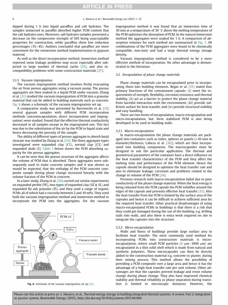
the air from porous aggregates using a vacuum pump. The porousaggregates are then soaked in a liquid PCM under vacuum. Zhanget al. [31] studied the vacuum impregnation of PCM into a granularmaterial that can be added to building materials such as concrete.Fig. 6 shows a schematic of the vacuum impregnation set up.
A comparative study was presented by Barreneche et al. [32]several gypsum samples with different PCM incorporationmethods (microencapsulation, direct incorporation and impreg-nation) were studied. Found that the effective thermal conductivitydecreased in all samples except in the impregnated one. This factwas due to the substitution of the air by the PCM in liquid state andhence decreasing the porosity of the sample.
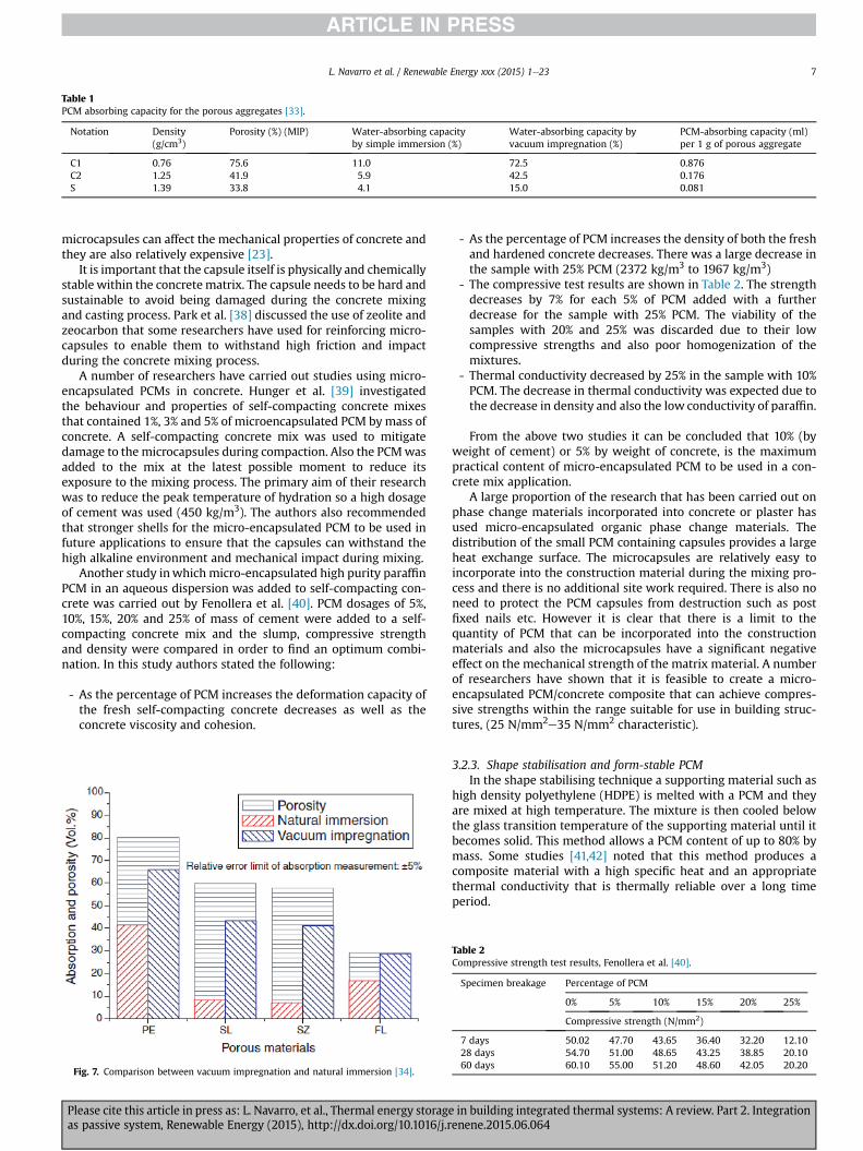
The ability of different types of porous aggregate to absorb butylstearate was studied by Zhang et al. [33]. The three aggregate typesinvestigated were expanded clay (C1), normal clay (C2) andexpanded shale (S). Table 1 below shows the PCM absorbing ca-pacity for the porous aggregates.
It can be seen that the porous structure of the aggregate affectsthe volume of PCM that is absorbed. These aggregates were sub-sequently used to make concrete samples and it was shown aswould be expected, that the enthalpy of the PCM concrete com-posite sample during phase change increased linearly with thevolume fraction of the PCM in concrete.
In a later study, Zhang et al. [34] carried out similar experimentson expanded perlite (PE), two types of expanded clay (SZ & SL) andexpanded fly ash granules (FL) and they used a range of organicPCMs all of which had a viscosity between 2 and 10 mPa. They usedboth the vacuum impregnation method and immersion method toincorporate the PCM into the aggregates. For the vacuum
impregnation method it was found that an immersion time of30 min at a temperature of 30 �C above the melting temperature ofthe PCM optimises the absorption of PCM. In the natural immersionmethod the aggregates were soaked for 1 h. A comparison of ab-sorption volumes for each method are summarised in Fig. 7. Allcombinations of the PCM aggregates were found to be chemicallycompatible, non-toxic and had a large thermal energy storagedensity.
Vacuum impregnation method is considered to be a moreeffective method of incorporation. No other advantage is demon-strated in the literature.
3.2. Encapsulation of phase change materials
Phase change materials can be encapsulated prior to incorpo-rating them into building elements. Regin et al. [35] stated fourprimary functions of the containment capsule: (i) meet the re-quirements of strength, flexibility, corrosion resistance and thermalstability, (ii) act as a barrier to protect the phase change materialfrom harmful interaction with the environment, (iii) provide suf-ficient surface for heat transfer, and (iv) provide structural stabilityand easy handling.
There are two forms of encapsulation, macro-encapsulation andmicro-encapsulation, but, form stabilized PCM is also beingdeveloped to be used in building walls.
3.2.1. Macro-encapsulationIn macro-encapsulation the phase change materials are pack-
aged into containers such as tubes, spheres or panels (>10 mm indiameter/thickness, Cabeza et al. [36]), which are then incorpo-rated into building components. The macrocapsules must bedesigned to suit the particular application. The thermal andgeometrical parameters of the container have a direct influence onthe heat transfer characteristics of the PCM and they affect themelting time and performance of the PCM element. Hence thecapsule should be designed to optimize the heat transfer rate andalso to eliminate leakage, corrosion and problems related to thechange in volume of the PCM [24].
Previous research with macro-encapsulation failed due to poorconductivity of the phase change material. When the heat energy isbeing released from the PCM capsule the PCM solidifies around theedges of the capsule and prevents effective heat transfer [37]. Alsothe heat transfer from the PCM is limited by the surface area of thecapsules and hence it can be difficult to achieve sufficient area forthe required heat transfer. Other practical disadvantages of usingmacro-encapsulated PCMs in buildings is that there is a risk thatthey could get damaged during the use of the building, e.g. drillingnails into walls, and also there is extra work required on site tointegrate the capsules into the structure.
3.2.2. Micro-encapsulationWalls and floors of buildings provide large surface area to
facilitate heat transfer. The most commonly used method forincorporating PCMs into construction materials is micro-encapsulation, where small PCM particles (1 mme1000 mm) areencapsulated in a thin solid shell which is made from natural andsynthetic polymers. These microcapsules can then be directlyadded to the construction material e.g. concrete or plaster, duringtheir mixing process. This method allows the possibility ofproviding a PCM composite over a large area and hence it has theadvantage of a high heat transfer rate per unit volume. Other ad-vantages are that the capsules prevent leakage and resist volumechange during phase change. They also have improved chemicalstability and thermal reliability as phase separation during transi-tion is limited to microscopic distances. However, theFig. 6. Schematic of the vacuum impregnation set up [31].
L. Navarro et al. / Renewable Energy xxx (2015) 1e236
Please cite this article in press as: L. Navarro, et al., Thermal energy storage in building integrated thermal systems: A review. Part 2. Integrationas passive system, Renewable Energy (2015), http://dx.doi.org/10.1016/j.renene.2015.06.064
microcapsules can affect the mechanical properties of concrete andthey are also relatively expensive [23].
It is important that the capsule itself is physically and chemicallystable within the concrete matrix. The capsule needs to be hard andsustainable to avoid being damaged during the concrete mixingand casting process. Park et al. [38] discussed the use of zeolite andzeocarbon that some researchers have used for reinforcing micro-capsules to enable them to withstand high friction and impactduring the concrete mixing process.
A number of researchers have carried out studies using micro-encapsulated PCMs in concrete. Hunger et al. [39] investigatedthe behaviour and properties of self-compacting concrete mixesthat contained 1%, 3% and 5% of microencapsulated PCM bymass ofconcrete. A self-compacting concrete mix was used to mitigatedamage to the microcapsules during compaction. Also the PCMwasadded to the mix at the latest possible moment to reduce itsexposure to the mixing process. The primary aim of their researchwas to reduce the peak temperature of hydration so a high dosageof cement was used (450 kg/m3). The authors also recommendedthat stronger shells for the micro-encapsulated PCM to be used infuture applications to ensure that the capsules can withstand thehigh alkaline environment and mechanical impact during mixing.
Another study inwhichmicro-encapsulated high purity paraffinPCM in an aqueous dispersion was added to self-compacting con-crete was carried out by Fenollera et al. [40]. PCM dosages of 5%,10%, 15%, 20% and 25% of mass of cement were added to a self-compacting concrete mix and the slump, compressive strengthand density were compared in order to find an optimum combi-nation. In this study authors stated the following:
- As the percentage of PCM increases the deformation capacity ofthe fresh self-compacting concrete decreases as well as theconcrete viscosity and cohesion.
- As the percentage of PCM increases the density of both the freshand hardened concrete decreases. There was a large decrease inthe sample with 25% PCM (2372 kg/m3 to 1967 kg/m3)
- The compressive test results are shown in Table 2. The strengthdecreases by 7% for each 5% of PCM added with a furtherdecrease for the sample with 25% PCM. The viability of thesamples with 20% and 25% was discarded due to their lowcompressive strengths and also poor homogenization of themixtures.
- Thermal conductivity decreased by 25% in the sample with 10%PCM. The decrease in thermal conductivity was expected due tothe decrease in density and also the low conductivity of paraffin.
From the above two studies it can be concluded that 10% (byweight of cement) or 5% by weight of concrete, is the maximumpractical content of micro-encapsulated PCM to be used in a con-crete mix application.
A large proportion of the research that has been carried out onphase change materials incorporated into concrete or plaster hasused micro-encapsulated organic phase change materials. Thedistribution of the small PCM containing capsules provides a largeheat exchange surface. The microcapsules are relatively easy toincorporate into the construction material during the mixing pro-cess and there is no additional site work required. There is also noneed to protect the PCM capsules from destruction such as postfixed nails etc. However it is clear that there is a limit to thequantity of PCM that can be incorporated into the constructionmaterials and also the microcapsules have a significant negativeeffect on the mechanical strength of the matrix material. A numberof researchers have shown that it is feasible to create a micro-encapsulated PCM/concrete composite that can achieve compres-sive strengths within the range suitable for use in building struc-tures, (25 N/mm2e35 N/mm2 characteristic).
3.2.3. Shape stabilisation and form-stable PCMIn the shape stabilising technique a supporting material such as
high density polyethylene (HDPE) is melted with a PCM and theyare mixed at high temperature. The mixture is then cooled belowthe glass transition temperature of the supporting material until itbecomes solid. This method allows a PCM content of up to 80% bymass. Some studies [41,42] noted that this method produces acomposite material with a high specific heat and an appropriatethermal conductivity that is thermally reliable over a long timeperiod.
Table 1PCM absorbing capacity for the porous aggregates [33].
Notation Density(g/cm3)
Porosity (%) (MIP) Water-absorbing capacityby simple immersion (%)
Water-absorbing capacity byvacuum impregnation (%)
PCM-absorbing capacity (ml)per 1 g of porous aggregate
C1 0.76 75.6 11.0 72.5 0.876C2 1.25 41.9 5.9 42.5 0.176S 1.39 33.8 4.1 15.0 0.081
Fig. 7. Comparison between vacuum impregnation and natural immersion [34].
Table 2Compressive strength test results, Fenollera et al. [40].
Specimen breakage Percentage of PCM
0% 5% 10% 15% 20% 25%
Compressive strength (N/mm2)
7 days 50.02 47.70 43.65 36.40 32.20 12.1028 days 54.70 51.00 48.65 43.25 38.85 20.1060 days 60.10 55.00 51.20 48.60 42.05 20.20
L. Navarro et al. / Renewable Energy xxx (2015) 1e23 7
Please cite this article in press as: L. Navarro, et al., Thermal energy storage in building integrated thermal systems: A review. Part 2. Integrationas passive system, Renewable Energy (2015), http://dx.doi.org/10.1016/j.renene.2015.06.064
Another type of composite PCM is known as form-stable com-posite PCM. A form-stable composite PCM retains an optimumpercentage of phase change material with no leakage above themelting temperature of the PCM. The terms ‘form-stable’ and‘shape stabilized’ appear to be used interchangeably in someresearch [42], however with form-stable composites it is notnecessary for the supporting material to be melted. Form-stablecomposites use immersion and vacuum impregnation methods toincorporate the PCM into the supporting materials [43,44].
Memon [23] presented a detailed summary of research carriedout using form-stable PCMs. Most of the research studied theformation of form-stable PCMs; however, there appears to be alack of research on the application of these composite materials.The type of supporting materials used included, diatomite,expanded perlite, expanded graphite, silica fume and groundgranular blast furnace slag (GGBS). GGBS is commonly used as apartial cement replacement in concrete so its use as a supportingmaterial for a form-stable PCM composite is of interest. A phasechange material, dodecyl alcohol (DA) was incorporated into theGGBS using vacuum impregnation in a study of Memon et al. [45].The maximum percentage of PCM retained without leakage was11% by weight. The composite had a melting temperature of21.16 �C and a latent heat of 22 J/g. Further research is required toestablish if this composite can be successfully used to effectivelyincrease the thermal energy storage of a building. As the amountof GGBS that can be used as cement replacement in concrete isusually limited to 30% of total cement content it may not befeasible to incorporate a sufficient amount of PCM into thestructure to make an effective difference to the thermal storagecapacity of the building.
3.3. Effect of the PCM incorporation method on the properties ofconcrete
3.3.1. WorkabilityHunger et al. [39] investigated the effect of micro-encapsulated
phase change material on the slump of a self-compacting concreteand found that all three PCM composites, 1%, 3% and 5% by masshad similar flow diameters. The 3% and 5% mixes exhibited aslightly higher viscosity however the self-compacting propertieswere not compromised.
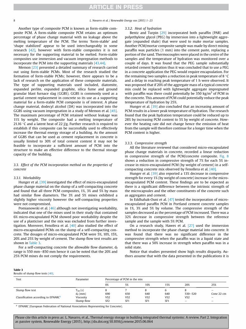
Pomianowski et al. [46] although not investigating workability,indicated that one of the mixes used in their study that contained6% micro-encapsulated PCM showed poor workability despite theuse of a plasticiser and the mix was excluded from further inves-tigation. Moreover, Fenollera et al. [40] also studied the effect ofmicro-encapsulated PCMs on the slump of a self-compacting con-crete. The dosages of micro-encapsulated PCM were 5%, 10%, 15%,20% and 25% by weight of cement. The slump flow test results areshown in Table 3.
For a self-compacting concrete the allowable flow diameter, dfrange is 550 mme850 mm hence it can be noted that the 20% and25% PCM mixes do not comply the requirements.
3.3.2. Heat of hydrationBentz and Turpin [29] incorporated both paraffin (PAR) and
polyethylene glycol (PEG) by immersion into a lightweight aggre-gate (expanded shale) that were used to make mortar samples.Another PCM/mortar composite sample was made by direct mixingparaffin wax particles (1 mm) into the cement paste, replacing aportion of the sand. Thermocouples were placed in the centre of thesamples and the temperature of hydration was monitored over acouple of days. It was found that the PEG sample substantiallyretarded cement hydration thus it was concluded that to use a PEGin a concrete application the PEG would require encapsulation. Forthe remaining two samples a reduction in peak temperature of 8 �Cand a delay in reaching peak temperature of 1 h were observed. Itwas proposed that if 20% of the aggregate mass of a typical concretemix could be replaced with lightweight aggregate impregnatedwith paraffin wax there could potentially be 350 kg/m3 of PCM inthe concrete. This amount of PCM could potentially reduce the peaktemperature of hydration by 25%.
Hunger et al. [39] also concluded that an increasing amount ofPCM results in a lower peak temperature of hydration. The researchfound that the peak hydration temperature could be reduced up to28% by increasing PCM content to 5% by weight of concrete. How-ever the heating rate did not change hence the emission of heatfrom the sample will therefore continue for a longer time when thePCM content is higher.
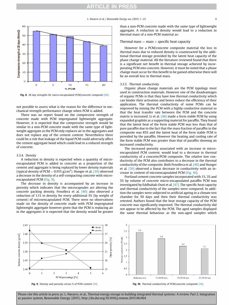
3.3.3. Compressive strengthAll the literature reviewed that considered micro-encapsulated
phase change materials in concrete, recorded a linear reductionin compressive strength of the PCM/concrete composite. Fig. 8shows a reduction in compressive strength of 7% for each 5% in-crease in micro-encapsulated PCM (by weight of cement) in a self-compacting concrete mix observed by Fenollera et al. [40].
Hunger et al. [39] also reported a 13% decrease in compressivestrength for every 1% (by weight of concrete) increase in the micro-encapsulated PCM content. These findings are to be expected asthere is a significant difference between the intrinsic strength ofthe microcapsules and the other constituents of the concrete suchas aggregates and cement.
In Eddhahak-Ouni et al. [47] tested the incorporation of micro-encapsulated paraffin PCM in Portland cement concrete samplesin 1%, 3% and 5% by volume. The compressive strength of thesamples decreased as the percentage of PCM increased. There was a32% decrease in compressive strength between the referencesample and the sample with 5% PCM.
On a research study, Hawes et al. [27] used the immersionmethod to incorporate the phase change material into concrete. Itwas found that there was no significant difference in thecompressive strength when the paraffin was in a liquid state andthat there was a 50% increase in strength when paraffin was in asolid state.
Notice that studies presented show high results disparity. Au-thors assume that with the data presented in the publications it is
Table 3Results of slump flow tests [40].
Test Parameter Percentage of PCM in the mix
0% 5% 10% 15% 20% 25%
Slump flow test T50 (s) 8 7 8 6 8 e
df (mm) 690 650 640 640 530e520 Cone 22 cmClassification according to EFNARCa Viscosity VS2 VS2 VS2 VS2 VS2 e
Slump flow SF2 SF1 SF1 SF1 e e
a EFNARC (European Federation of National Associations Representing for Concrete).
L. Navarro et al. / Renewable Energy xxx (2015) 1e238
Please cite this article in press as: L. Navarro, et al., Thermal energy storage in building integrated thermal systems: A review. Part 2. Integrationas passive system, Renewable Energy (2015), http://dx.doi.org/10.1016/j.renene.2015.06.064
not possible to assess what is the reason for the difference in me-chanical strength performance change when PCM is added.
There was no report found on the compressive strength ofconcrete made with PCM impregnated lightweight aggregate.However, it is expected that the compressive strength would besimilar to a non-PCM concrete made with the same type of light-weight aggregate as the PCM only replaces air in the aggregates anddoes not replace any of the cement content. Nevertheless therecould be a risk that leakage of the liquid PCM could adversely affectthe cement aggregate bond which could lead to a reduced strengthof concrete.
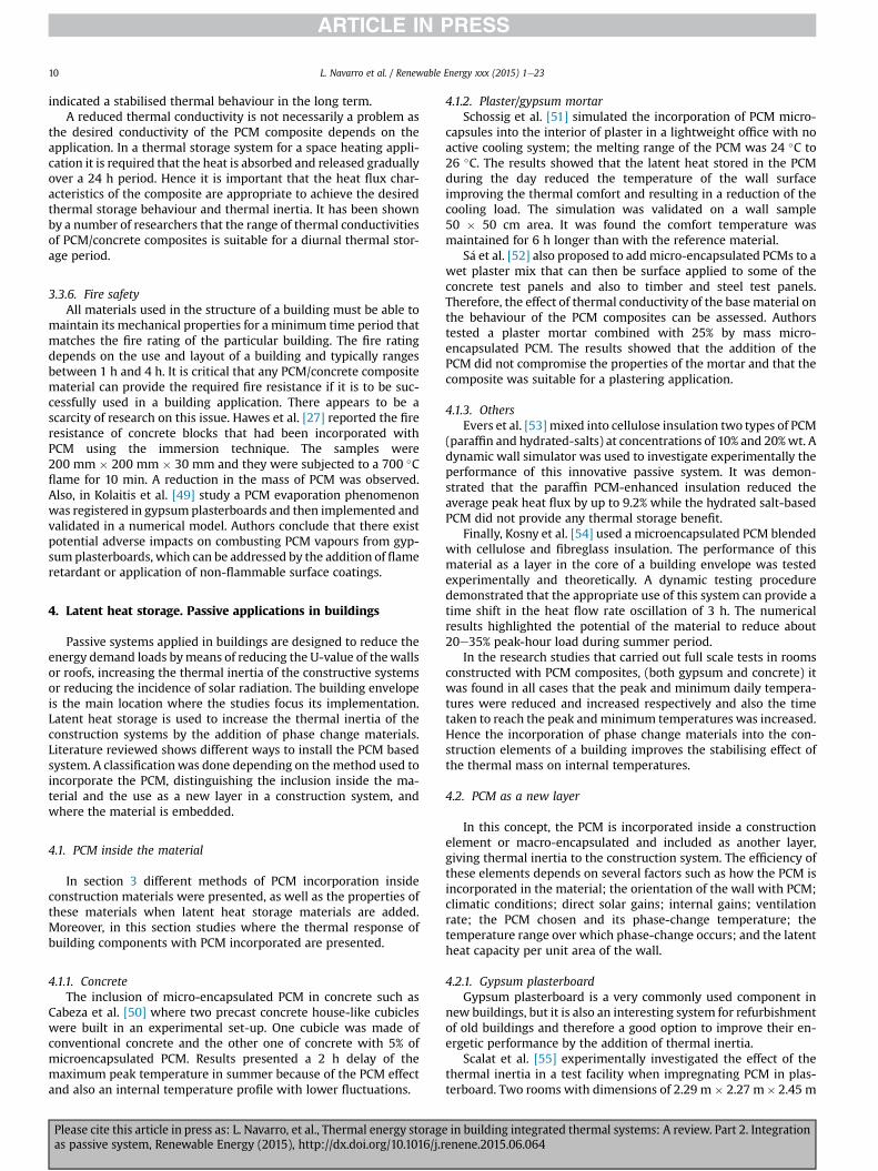
3.3.4. DensityA reduction in density is expected when a quantity of micro-
encapsulated PCM is added to concrete as a proportion of thecement and aggregate is being replaced by lower density materials(typical density of PCM ¼ 0.915 g/cm3). Hunger et al. [39] observeda decrease in the density of a self-compacting concrete with micro-encapsulated PCM (Fig. 9).
The decrease in density is accompanied by an increase inporosity which indicates that the microcapsules are altering theconcrete packing density. Fenollera et al. [40] also observed areduction of 1.1% in density for every additional 5% (by weight ofcement) of microencapsulated PCM. There were no observationsmade on the density of concrete made with PCM impregnatedlightweight aggregate however given that the PCM is replacing airin the aggregates it is expected that the density would be greater
than a non-PCM concrete made with the same type of lightweightaggregate. A reduction in density would lead to a reduction inthermal mass of a non-PCM material as:
Thermal mass ¼ mass� specific heat capacity
However for a PCM/concrete composite material the loss inthermal mass due to reduced density is counteracted by the addi-tional thermal storage provided by the latent heat capacity of thephase change material. All the literature reviewed found that thereis a significant net benefit in thermal storage achieved by incor-porating PCM into concrete. However, it must be noted that a phasechangemust occur for this benefit to be gained otherwise there willbe an overall loss in thermal mass.
3.3.5. Thermal conductivityOrganic phase change materials are the PCM typology most
used in construction materials. However one of the disadvantagesof organic PCMs is that they have low thermal conductivity whichcan hinder their activation and hence reduce the efficiency of theirapplication. The thermal conductivity of some PCMs can beimproved by mixing the PCM with a highly conductive material sothat the heat transfer rate between the PCM and the concretematrix is increased. Li et al. [48] made a form stable PCM by usingexpanded graphite as a supportingmaterial for paraffin. They foundthat the latent heat of the form stable PCM was less than that ofpure paraffin due to the fact that the mass fraction of paraffin in thecomposite was 85% and the latent heat of the form stable PCM isprovided by the paraffin. However the heating and cooling rate ofthe form stable PCM was greater than that of paraffin showing anincreased conductivity.
The increased porosity associated with an increase in micro-encapsulated PCM content, would lead to a decrease in thermalconductivity of a concrete/PCM composite. The relative low con-ductivity of the PCM also contributes to a decrease in the thermalconductivity of the composite. Both Fenollera et al. [40] and Hungeret al. [39] observed a linear decrease in conductivity with an in-crease in content of microencapsulated PCM (Fig. 10).
Portland cement concrete samples incorporatedwith 1%, 3% and5% by volume of concrete micro-encapsulated paraffin PCM wasinvestigated by Eddhahak-Ouni et al. [47]. The specific heat capacityand thermal conductivity of the samples were compared. In addi-tion the samples were subjected to artificial ageing in a climate testchamber for 50 days and then their thermal conductivity wasretested. Authors found that the heat storage capacity of the PCMconcrete was significantly improved. The thermal conductivity didnot appear to be affected by the PCM. The aged samples displayedthe same thermal behaviour as the non-aged samples which
Fig. 9. Density and porosity versus % of PCM content [39]. Fig. 10. Thermal conductivity of PCM/concrete composite [39].
Fig. 8. 28 day strengths for micro-encapsulated PCM/concrete composite [40].
L. Navarro et al. / Renewable Energy xxx (2015) 1e23 9
Please cite this article in press as: L. Navarro, et al., Thermal energy storage in building integrated thermal systems: A review. Part 2. Integrationas passive system, Renewable Energy (2015), http://dx.doi.org/10.1016/j.renene.2015.06.064
indicated a stabilised thermal behaviour in the long term.A reduced thermal conductivity is not necessarily a problem as
the desired conductivity of the PCM composite depends on theapplication. In a thermal storage system for a space heating appli-cation it is required that the heat is absorbed and released graduallyover a 24 h period. Hence it is important that the heat flux char-acteristics of the composite are appropriate to achieve the desiredthermal storage behaviour and thermal inertia. It has been shownby a number of researchers that the range of thermal conductivitiesof PCM/concrete composites is suitable for a diurnal thermal stor-age period.
3.3.6. Fire safetyAll materials used in the structure of a building must be able to
maintain its mechanical properties for a minimum time period thatmatches the fire rating of the particular building. The fire ratingdepends on the use and layout of a building and typically rangesbetween 1 h and 4 h. It is critical that any PCM/concrete compositematerial can provide the required fire resistance if it is to be suc-cessfully used in a building application. There appears to be ascarcity of research on this issue. Hawes et al. [27] reported the fireresistance of concrete blocks that had been incorporated withPCM using the immersion technique. The samples were200 mm � 200 mm � 30 mm and they were subjected to a 700 �Cflame for 10 min. A reduction in the mass of PCM was observed.Also, in Kolaitis et al. [49] study a PCM evaporation phenomenonwas registered in gypsum plasterboards and then implemented andvalidated in a numerical model. Authors conclude that there existpotential adverse impacts on combusting PCM vapours from gyp-sum plasterboards, which can be addressed by the addition of flameretardant or application of non-flammable surface coatings.
4. Latent heat storage. Passive applications in buildings
Passive systems applied in buildings are designed to reduce theenergy demand loads bymeans of reducing the U-value of thewallsor roofs, increasing the thermal inertia of the constructive systemsor reducing the incidence of solar radiation. The building envelopeis the main location where the studies focus its implementation.Latent heat storage is used to increase the thermal inertia of theconstruction systems by the addition of phase change materials.Literature reviewed shows different ways to install the PCM basedsystem. A classificationwas done depending on the method used toincorporate the PCM, distinguishing the inclusion inside the ma-terial and the use as a new layer in a construction system, andwhere the material is embedded.
4.1. PCM inside the material
In section 3 different methods of PCM incorporation insideconstruction materials were presented, as well as the properties ofthese materials when latent heat storage materials are added.Moreover, in this section studies where the thermal response ofbuilding components with PCM incorporated are presented.
4.1.1. ConcreteThe inclusion of micro-encapsulated PCM in concrete such as
Cabeza et al. [50] where two precast concrete house-like cubicleswere built in an experimental set-up. One cubicle was made ofconventional concrete and the other one of concrete with 5% ofmicroencapsulated PCM. Results presented a 2 h delay of themaximum peak temperature in summer because of the PCM effectand also an internal temperature profile with lower fluctuations.
4.1.2. Plaster/gypsum mortarSchossig et al. [51] simulated the incorporation of PCM micro-
capsules into the interior of plaster in a lightweight office with noactive cooling system; the melting range of the PCM was 24 �C to26 �C. The results showed that the latent heat stored in the PCMduring the day reduced the temperature of the wall surfaceimproving the thermal comfort and resulting in a reduction of thecooling load. The simulation was validated on a wall sample50 � 50 cm area. It was found the comfort temperature wasmaintained for 6 h longer than with the reference material.
S�a et al. [52] also proposed to addmicro-encapsulated PCMs to awet plaster mix that can then be surface applied to some of theconcrete test panels and also to timber and steel test panels.Therefore, the effect of thermal conductivity of the basematerial onthe behaviour of the PCM composites can be assessed. Authorstested a plaster mortar combined with 25% by mass micro-encapsulated PCM. The results showed that the addition of thePCM did not compromise the properties of the mortar and that thecomposite was suitable for a plastering application.
4.1.3. OthersEvers et al. [53] mixed into cellulose insulation two types of PCM
(paraffin and hydrated-salts) at concentrations of 10% and 20%wt. Adynamic wall simulator was used to investigate experimentally theperformance of this innovative passive system. It was demon-strated that the paraffin PCM-enhanced insulation reduced theaverage peak heat flux by up to 9.2% while the hydrated salt-basedPCM did not provide any thermal storage benefit.
Finally, Kosny et al. [54] used a microencapsulated PCM blendedwith cellulose and fibreglass insulation. The performance of thismaterial as a layer in the core of a building envelope was testedexperimentally and theoretically. A dynamic testing proceduredemonstrated that the appropriate use of this system can provide atime shift in the heat flow rate oscillation of 3 h. The numericalresults highlighted the potential of the material to reduce about20e35% peak-hour load during summer period.
In the research studies that carried out full scale tests in roomsconstructed with PCM composites, (both gypsum and concrete) itwas found in all cases that the peak and minimum daily tempera-tures were reduced and increased respectively and also the timetaken to reach the peak andminimum temperatures was increased.Hence the incorporation of phase change materials into the con-struction elements of a building improves the stabilising effect ofthe thermal mass on internal temperatures.
4.2. PCM as a new layer
In this concept, the PCM is incorporated inside a constructionelement or macro-encapsulated and included as another layer,giving thermal inertia to the construction system. The efficiency ofthese elements depends on several factors such as how the PCM isincorporated in the material; the orientation of the wall with PCM;climatic conditions; direct solar gains; internal gains; ventilationrate; the PCM chosen and its phase-change temperature; thetemperature range over which phase-change occurs; and the latentheat capacity per unit area of the wall.
4.2.1. Gypsum plasterboardGypsum plasterboard is a very commonly used component in
new buildings, but it is also an interesting system for refurbishmentof old buildings and therefore a good option to improve their en-ergetic performance by the addition of thermal inertia.
Scalat et al. [55] experimentally investigated the effect of thethermal inertia in a test facility when impregnating PCM in plas-terboard. Two rooms with dimensions of 2.29 m � 2.27 m� 2.45 m
L. Navarro et al. / Renewable Energy xxx (2015) 1e2310
Please cite this article in press as: L. Navarro, et al., Thermal energy storage in building integrated thermal systems: A review. Part 2. Integrationas passive system, Renewable Energy (2015), http://dx.doi.org/10.1016/j.renene.2015.06.064
were built for testing. One room contained PCM impregnatedgypsum wallboard on the interior walls and ceiling, and the otherroom had ordinary gypsum walls. An insulated wall separated thetwo rooms and each of them had an air conditioning unit. Thewallboard was immersed in PCM 50% butyl stearate and 48% butylpalmitate for 1.5e4 min depending on the dimensions of thewallboard. During winter tests, the air temperature of the roomwith conventional gypsum wallboard was found to fall from 24 �Cto 16 �C in 15.1 h; however, the PCM wallboard took 35.5 h todecrease the same thermal gradient due to the thermally chargedPCM. Under cooling mode it was found the ordinary wallboardincreased from 16 �C to 22 �C in 27.2 h compared to the PCMwallboard which maintained the temperature below 22 �C for 50 h.Under real conditions, the effect of room occupancy, lights andother sources of heat from electrical devices may affect the roomtemperature further than was reflected in these results.
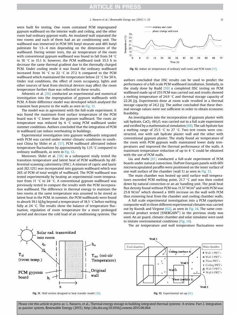
Athientis et al. [56] conducted an experimental and numericalinvestigation into the impregnation of gypsum wallboards withPCM. A finite difference model was developed which analysed thetransient heat process in the walls as seen in Fig. 11.
The model was in agreement with the full-scale experiment. Itwas found the maximum front surface temperature of the PCMboard was 6 �C lower than the gypsum wallboard. The room airtemperature was reduced by 4 �C using PCM wallboard undersummer conditions. Authors concluded that the integration of PCMin wallboard can reduce overheating in buildings.
Experimental investigation into gypsum wallboards integratedwith PCM was carried under winter climatic conditions in south-east China by Shilei et al. [57]. PCM wallboard alleviated indoortemperature fluctuations by approximately by 1.15 �C compared toordinary wallboards, as seen in Fig. 12.
Moreover, Shilei et al. [58] in a subsequent study tested thetransition temperature and latent heat of PCM wallboards by dif-ferential scanning calorimetry (DSC). A mixture of capric and lauricacid (82:12%) was incorporated into gypsum wallboard which was26% of PCM of total weight of wallboard. The PCM wallboard wastested experimentally by heating an experimental room tempera-ture from 11 �C to 24 �C. A conventional gypsum wallboard waspreviously tested to compare the results with the PCM incorpora-tion wallboard. The difference in thermal energy to maintain thetwo rooms at the same temperature was assumed to be stored aslatent heat in the PCM. In summer, the PCMwallboards were foundto absorb 39.1 kJ/kg beyond a temperature of 18.5 �C beforemeltingfully at 24 �C. The results show the balance of temperature fluc-tuation, regulation of room temperature for a more prolongedperiod and decrease the cold load of air conditioning systems. The
authors concluded that DSC results can be used to predict theperformance of a full-scale PCMwallboard installation. Similarly, inthe study done by Rudd [59] a completed DSC testing on PCMwallboard made up of 25% PCMwas carried out and results showeda melting temperature of 24.9 �C and thermal storage capacity of22.26 J/g. Experiments done at room scale resulted in a thermalstorage capacity of 24.2 J/g. The author concluded that these ther-mal storage values were not sufficient in order to obtain economicfeasibility.
An investigation into the incorporation of gypsum plaster withsalt hydrate, CaCl2$6H2O, was carried out in a full scale experimentand verified by amathematical simulation [60]. The salt hydrate hasa melting range of 25.5 �C to 27 �C. Two test rooms were con-structed, one with salt hydrate plaster wall and the other withconventional gypsum plaster. The study found air temperature ofthe room with PCM gypsum walls maintained lower daily tem-peratures and improved the thermal performance of the walls. Amaximum temperature reduction of up to 4 �C could be obtainedwith the use of PCM walls.
Liu and Awbi [61] conducted a full-scale experiment of PCMboards under natural convection. DuPont Energain panels with 60%microencapsulated paraffinwere positioned on the inner surface ofone wall surface of the chamber (wall 5) as seen in Fig. 13.
The main chamber was heated up until surface wall tempera-tures exceeded PCM melting point, 21.7 �C and was then cooleddown by natural convection or an air handling unit. The peak heatflux density foundwithout PCMwas 11.57W/m2 andwith PCMwas25.8 W/m2 which showed a 100% increase on the wall with PCMthus removing heat from the chamber and cooling chamber walls.
A full scale experimental investigation into a PCM copolymercompositewall in three different experimental climateswas carriedout by Kuznik and Virgone [62], as seen in Fig. 14. The same com-mercial product tested (ENERGAIN®) in the previous study wasused. An air guard, climatic chamber and solar simulator were usedto imitate environmental conditions (Fig. 14).
The air temperature and wall temperature fluctuations were
Fig. 11. Wall section designed in heat transfer model [56].
Fig. 12. Indoor air temperature of ordinary wall room and PCM room [57].
Fig. 13. Experimental set-up [61].
L. Navarro et al. / Renewable Energy xxx (2015) 1e23 11
Please cite this article in press as: L. Navarro, et al., Thermal energy storage in building integrated thermal systems: A review. Part 2. Integrationas passive system, Renewable Energy (2015), http://dx.doi.org/10.1016/j.renene.2015.06.064
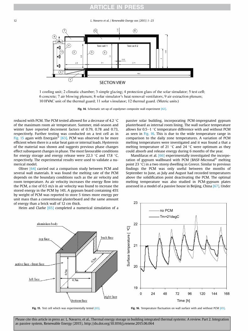
reduced with PCM. The PCM tested allowed for a decrease of 4.2 �Cof the maximum room air temperature. Summer, mid-season andwinter have reported decrement factors of 0.79, 0.78 and 0.73,respectively. Further testing was conducted on a test cell as inFig. 15 again with Energain® [63]. PCM was observed to be moreefficient when there is a solar heat gain or internal loads. Hysteresisof the material was shown and suggests previous phase changeseffect subsequent changes in phase. Themost favourable conditionsfor energy storage and energy release were 22.3 �C and 17.8 �C,respectively. The experimental results were used to validate a nu-merical model.
Oliver [64] carried out a comparison study between PCM andseveral wall materials. It was found the melting rate of the PCMdepends on the boundary conditions such as the air velocity androom temperature. As air velocity increases the energy flow intothe PCM, a rise of 0.5 m/s in air velocity was found to increase thestored energy in the PCM by 14%. A gypsum board containing 45%by weight of PCM was reported to store 5 times more energy perunit mass than a conventional plasterboard and the same amountof energy than a brick wall of 12 cm thick.
Heim and Clarke [65] completed a numerical simulation of a
passive solar building, incorporating PCM-impregnated gypsumplasterboard as internal room lining. The wall surface temperatureallows for 0.5e1 �C temperature difference with and without PCMas seen in Fig. 16. This is due to the wide temperature range incomparison to the daily zone temperatures. A variation of PCMmelting temperatures were investigated and it was found a that amelting temperature of 21 �C and 24 �C were optimum as theycould absorb and release energy during 6 months of the year.
Mandilaras et al. [66] experimentally investigated the incorpo-ration of gypsum wallboard with PCM (BASF-Micronal® meltingpoint 23 �C) in a two storey dwelling in Greece. Similar to previousfindings the PCM was only useful between the months ofSeptember to June, as July and August had recorded temperaturesabove the solidification point deactivating the PCM. The optimalmelting temperature was also studied in PCM-gypsum platesassessed in a model of a passive house in Beijing, China [67]. Under
Fig. 14. Schematic set-up of copolymer composite wall experiment [62].
Fig. 15. Test cell which was experimentally tested [63]. Fig. 16. Temperature fluctuation on wall surface with and without PCM [65].
L. Navarro et al. / Renewable Energy xxx (2015) 1e2312
Please cite this article in press as: L. Navarro, et al., Thermal energy storage in building integrated thermal systems: A review. Part 2. Integrationas passive system, Renewable Energy (2015), http://dx.doi.org/10.1016/j.renene.2015.06.064
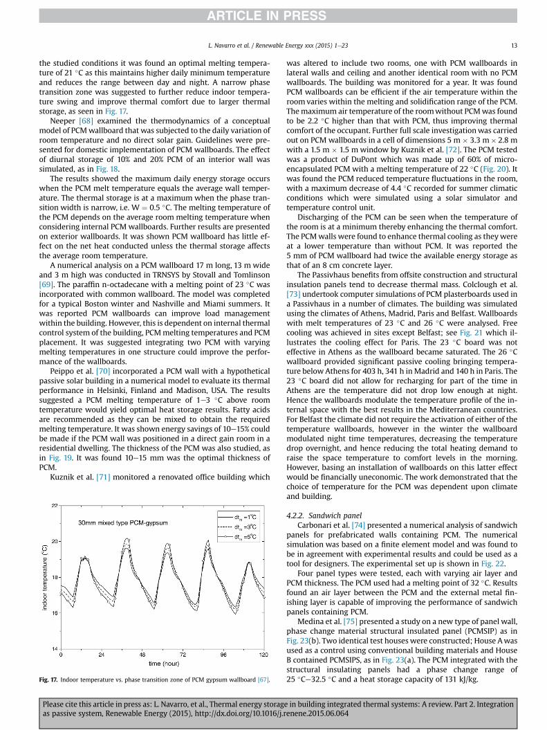
the studied conditions it was found an optimal melting tempera-ture of 21 �C as this maintains higher daily minimum temperatureand reduces the range between day and night. A narrow phasetransition zone was suggested to further reduce indoor tempera-ture swing and improve thermal comfort due to larger thermalstorage, as seen in Fig. 17.
Neeper [68] examined the thermodynamics of a conceptualmodel of PCMwallboard that was subjected to the daily variation ofroom temperature and no direct solar gain. Guidelines were pre-sented for domestic implementation of PCM wallboards. The effectof diurnal storage of 10% and 20% PCM of an interior wall wassimulated, as in Fig. 18.
The results showed the maximum daily energy storage occurswhen the PCM melt temperature equals the average wall temper-ature. The thermal storage is at a maximum when the phase tran-sition width is narrow, i.e. W ¼ 0.5 �C. The melting temperature ofthe PCM depends on the average room melting temperature whenconsidering internal PCM wallboards. Further results are presentedon exterior wallboards. It was shown PCM wallboard has little ef-fect on the net heat conducted unless the thermal storage affectsthe average room temperature.
A numerical analysis on a PCM wallboard 17 m long, 13 m wideand 3 m high was conducted in TRNSYS by Stovall and Tomlinson[69]. The paraffin n-octadecane with a melting point of 23 �C wasincorporated with common wallboard. The model was completedfor a typical Boston winter and Nashville and Miami summers. Itwas reported PCM wallboards can improve load managementwithin the building. However, this is dependent on internal thermalcontrol system of the building, PCMmelting temperatures and PCMplacement. It was suggested integrating two PCM with varyingmelting temperatures in one structure could improve the perfor-mance of the wallboards.
Peippo et al. [70] incorporated a PCM wall with a hypotheticalpassive solar building in a numerical model to evaluate its thermalperformance in Helsinki, Finland and Madison, USA. The resultssuggested a PCM melting temperature of 1e3 �C above roomtemperature would yield optimal heat storage results. Fatty acidsare recommended as they can be mixed to obtain the requiredmelting temperature. It was shown energy savings of 10e15% couldbe made if the PCM wall was positioned in a direct gain room in aresidential dwelling. The thickness of the PCM was also studied, asin Fig. 19. It was found 10e15 mm was the optimal thickness ofPCM.
Kuznik et al. [71] monitored a renovated office building which
was altered to include two rooms, one with PCM wallboards inlateral walls and ceiling and another identical room with no PCMwallboards. The building was monitored for a year. It was foundPCM wallboards can be efficient if the air temperature within theroomvaries within the melting and solidification range of the PCM.Themaximum air temperature of the roomwithout PCMwas foundto be 2.2 �C higher than that with PCM, thus improving thermalcomfort of the occupant. Further full scale investigationwas carriedout on PCM wallboards in a cell of dimensions 5 m � 3.3 m� 2.8 mwith a 1.5 m � 1.5 m window by Kuznik et al. [72]. The PCM testedwas a product of DuPont which was made up of 60% of micro-encapsulated PCM with a melting temperature of 22 �C (Fig. 20). Itwas found the PCM reduced temperature fluctuations in the room,with a maximum decrease of 4.4 �C recorded for summer climaticconditions which were simulated using a solar simulator andtemperature control unit.
Discharging of the PCM can be seen when the temperature ofthe room is at a minimum thereby enhancing the thermal comfort.The PCMwalls were found to enhance thermal cooling as theywereat a lower temperature than without PCM. It was reported the5 mm of PCM wallboard had twice the available energy storage asthat of an 8 cm concrete layer.
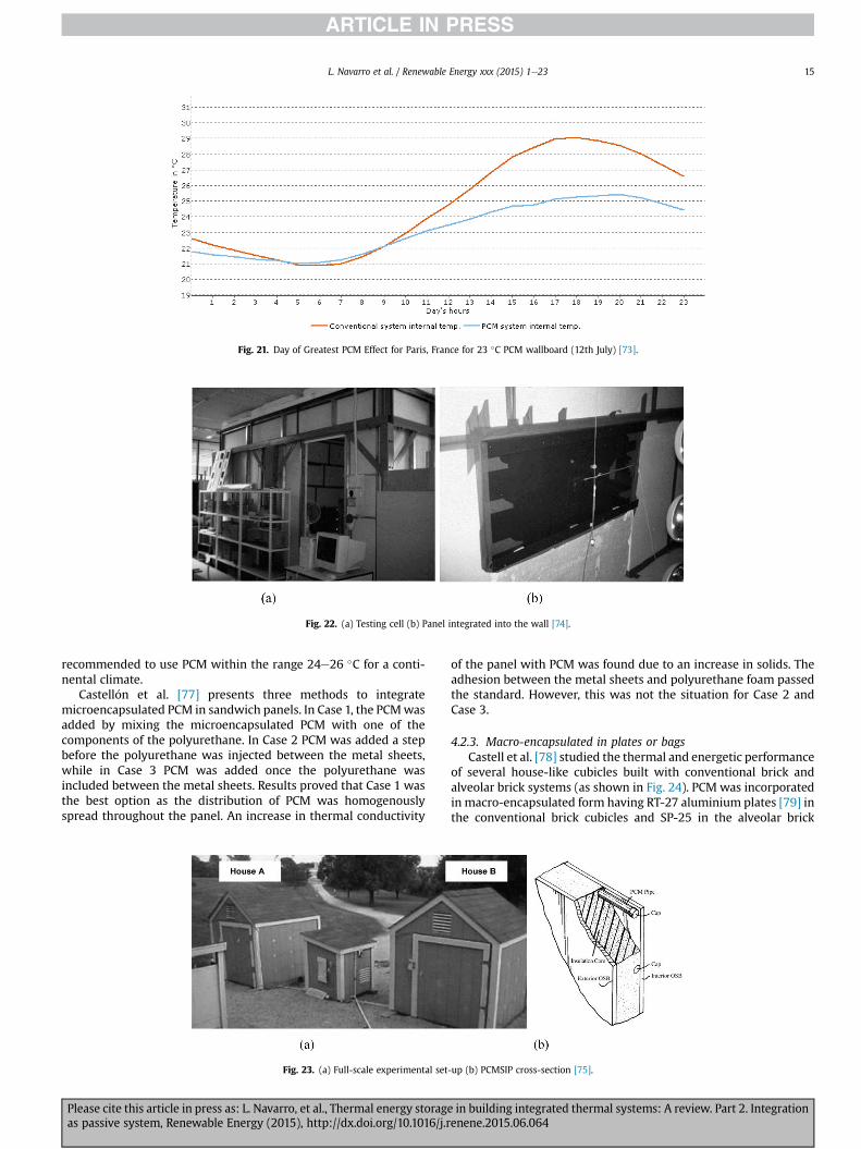
The Passivhaus benefits from offsite construction and structuralinsulation panels tend to decrease thermal mass. Colclough et al.[73] undertook computer simulations of PCM plasterboards used ina Passivhaus in a number of climates. The building was simulatedusing the climates of Athens, Madrid, Paris and Belfast. Wallboardswith melt temperatures of 23 �C and 26 �C were analysed. Freecooling was achieved in sites except Belfast; see Fig. 21 which il-lustrates the cooling effect for Paris. The 23 �C board was noteffective in Athens as the wallboard became saturated. The 26 �Cwallboard provided significant passive cooling bringing tempera-ture below Athens for 403 h, 341 h inMadrid and 140 h in Paris. The23 �C board did not allow for recharging for part of the time inAthens are the temperature did not drop low enough at night.Hence the wallboards modulate the temperature profile of the in-ternal space with the best results in the Mediterranean countries.For Belfast the climate did not require the activation of either of thetemperature wallboards, however in the winter the wallboardmodulated night time temperatures, decreasing the temperaturedrop overnight, and hence reducing the total heating demand toraise the space temperature to comfort levels in the morning.However, basing an installation of wallboards on this latter effectwould be financially uneconomic. The work demonstrated that thechoice of temperature for the PCM was dependent upon climateand building.
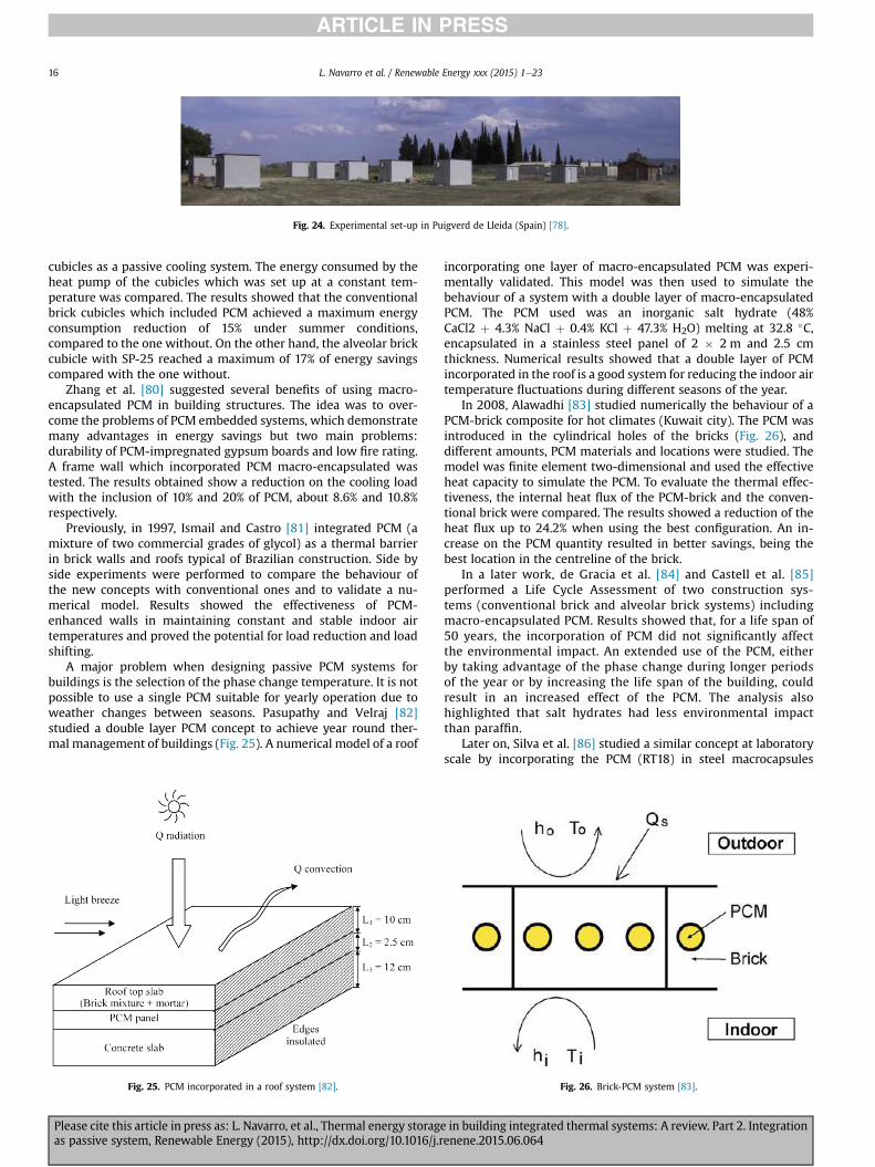
4.2.2. Sandwich panelCarbonari et al. [74] presented a numerical analysis of sandwich
panels for prefabricated walls containing PCM. The numericalsimulation was based on a finite element model and was found tobe in agreement with experimental results and could be used as atool for designers. The experimental set up is shown in Fig. 22.
Four panel types were tested, each with varying air layer andPCM thickness. The PCM used had a melting point of 32 �C. Resultsfound an air layer between the PCM and the external metal fin-ishing layer is capable of improving the performance of sandwichpanels containing PCM.
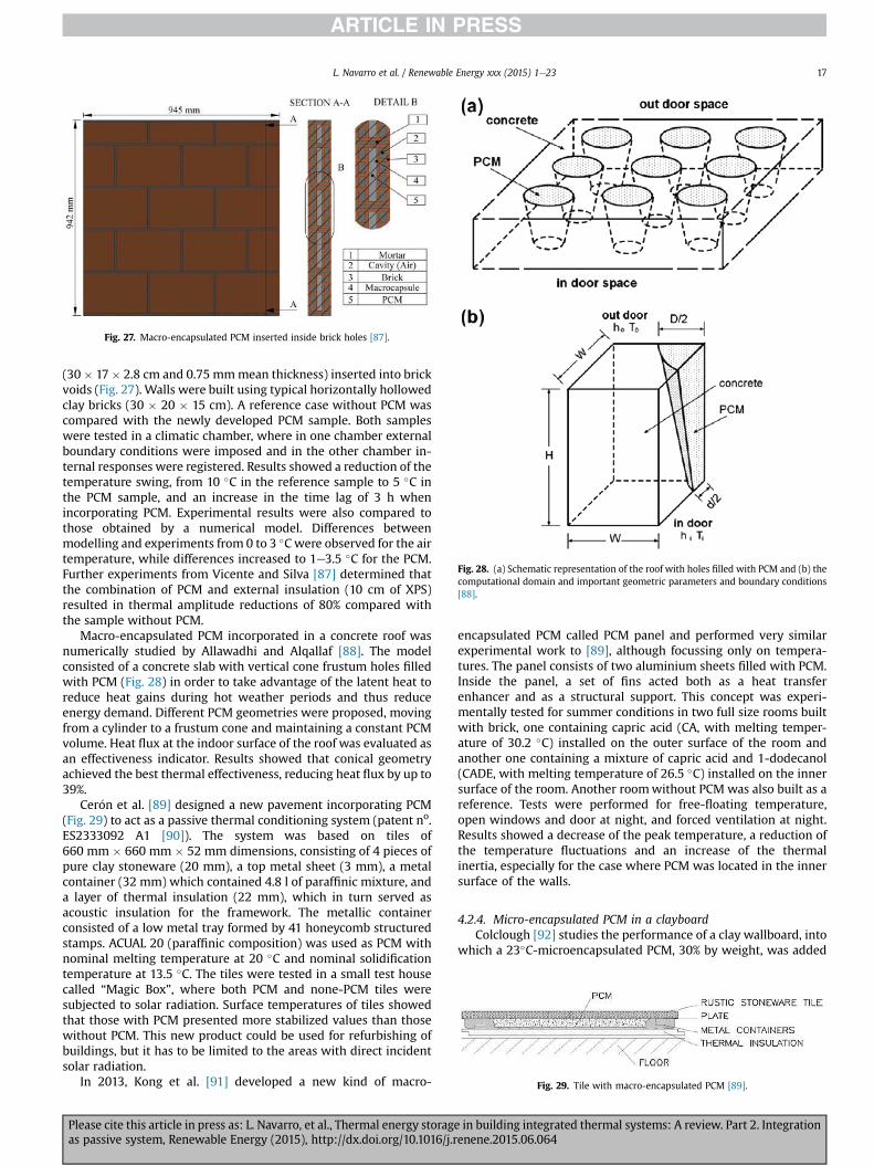
Medina et al. [75] presented a study on a new type of panel wall,phase change material structural insulated panel (PCMSIP) as inFig. 23(b). Two identical test houses were constructed; House Awasused as a control using conventional building materials and HouseB contained PCMSIPS, as in Fig. 23(a). The PCM integrated with thestructural insulating panels had a phase change range of25 �Ce32.5 �C and a heat storage capacity of 131 kJ/kg.Fig. 17. Indoor temperature vs. phase transition zone of PCM gypsum wallboard [67].
L. Navarro et al. / Renewable Energy xxx (2015) 1e23 13
Please cite this article in press as: L. Navarro, et al., Thermal energy storage in building integrated thermal systems: A review. Part 2. Integrationas passive system, Renewable Energy (2015), http://dx.doi.org/10.1016/j.renene.2015.06.064
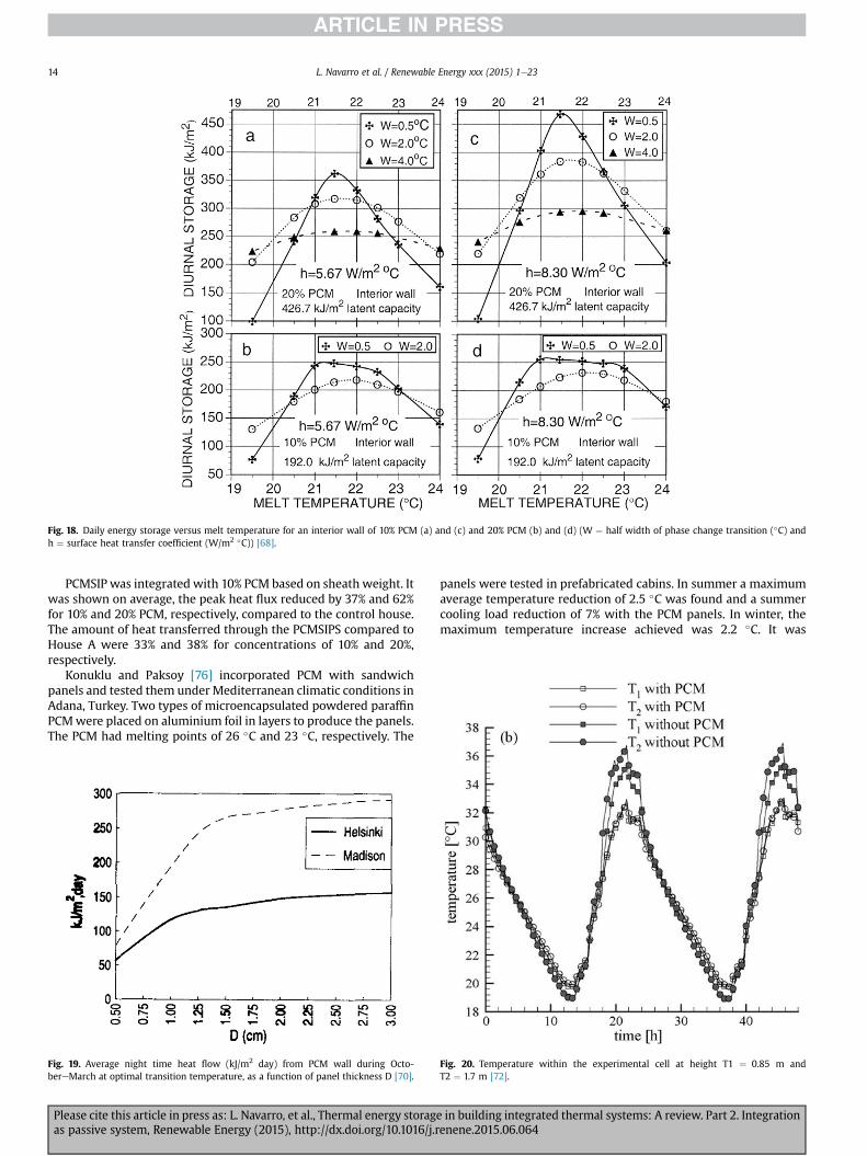
PCMSIP was integrated with 10% PCM based on sheath weight. Itwas shown on average, the peak heat flux reduced by 37% and 62%for 10% and 20% PCM, respectively, compared to the control house.The amount of heat transferred through the PCMSIPS compared toHouse A were 33% and 38% for concentrations of 10% and 20%,respectively.
Konuklu and Paksoy [76] incorporated PCM with sandwichpanels and tested them underMediterranean climatic conditions inAdana, Turkey. Two types of microencapsulated powdered paraffinPCMwere placed on aluminium foil in layers to produce the panels.The PCM had melting points of 26 �C and 23 �C, respectively. The
panels were tested in prefabricated cabins. In summer a maximumaverage temperature reduction of 2.5 �C was found and a summercooling load reduction of 7% with the PCM panels. In winter, themaximum temperature increase achieved was 2.2 �C. It was
Fig. 18. Daily energy storage versus melt temperature for an interior wall of 10% PCM (a) and (c) and 20% PCM (b) and (d) (W ¼ half width of phase change transition (�C) andh ¼ surface heat transfer coefficient (W/m2 �C)) [68].
Fig. 19. Average night time heat flow (kJ/m2 day) from PCM wall during Octo-bereMarch at optimal transition temperature, as a function of panel thickness D [70].
Fig. 20. Temperature within the experimental cell at height T1 ¼ 0.85 m andT2 ¼ 1.7 m [72].
L. Navarro et al. / Renewable Energy xxx (2015) 1e2314
Please cite this article in press as: L. Navarro, et al., Thermal energy storage in building integrated thermal systems: A review. Part 2. Integrationas passive system, Renewable Energy (2015), http://dx.doi.org/10.1016/j.renene.2015.06.064
recommended to use PCM within the range 24e26 �C for a conti-nental climate.
Castell�on et al. [77] presents three methods to integratemicroencapsulated PCM in sandwich panels. In Case 1, the PCMwasadded by mixing the microencapsulated PCM with one of thecomponents of the polyurethane. In Case 2 PCM was added a stepbefore the polyurethane was injected between the metal sheets,while in Case 3 PCM was added once the polyurethane wasincluded between the metal sheets. Results proved that Case 1 wasthe best option as the distribution of PCM was homogenouslyspread throughout the panel. An increase in thermal conductivity
of the panel with PCM was found due to an increase in solids. Theadhesion between the metal sheets and polyurethane foam passedthe standard. However, this was not the situation for Case 2 andCase 3.
4.2.3. Macro-encapsulated in plates or bagsCastell et al. [78] studied the thermal and energetic performance
of several house-like cubicles built with conventional brick andalveolar brick systems (as shown in Fig. 24). PCM was incorporatedin macro-encapsulated form having RT-27 aluminium plates [79] inthe conventional brick cubicles and SP-25 in the alveolar brick
Fig. 21. Day of Greatest PCM Effect for Paris, France for 23 �C PCM wallboard (12th July) [73].
Fig. 22. (a) Testing cell (b) Panel integrated into the wall [74].
Fig. 23. (a) Full-scale experimental set-up (b) PCMSIP cross-section [75].
L. Navarro et al. / Renewable Energy xxx (2015) 1e23 15
Please cite this article in press as: L. Navarro, et al., Thermal energy storage in building integrated thermal systems: A review. Part 2. Integrationas passive system, Renewable Energy (2015), http://dx.doi.org/10.1016/j.renene.2015.06.064
cubicles as a passive cooling system. The energy consumed by theheat pump of the cubicles which was set up at a constant tem-perature was compared. The results showed that the conventionalbrick cubicles which included PCM achieved a maximum energyconsumption reduction of 15% under summer conditions,compared to the one without. On the other hand, the alveolar brickcubicle with SP-25 reached a maximum of 17% of energy savingscompared with the one without.
Zhang et al. [80] suggested several benefits of using macro-encapsulated PCM in building structures. The idea was to over-come the problems of PCM embedded systems, which demonstratemany advantages in energy savings but two main problems:durability of PCM-impregnated gypsum boards and low fire rating.A frame wall which incorporated PCM macro-encapsulated wastested. The results obtained show a reduction on the cooling loadwith the inclusion of 10% and 20% of PCM, about 8.6% and 10.8%respectively.
Previously, in 1997, Ismail and Castro [81] integrated PCM (amixture of two commercial grades of glycol) as a thermal barrierin brick walls and roofs typical of Brazilian construction. Side byside experiments were performed to compare the behaviour ofthe new concepts with conventional ones and to validate a nu-merical model. Results showed the effectiveness of PCM-enhanced walls in maintaining constant and stable indoor airtemperatures and proved the potential for load reduction and loadshifting.
A major problem when designing passive PCM systems forbuildings is the selection of the phase change temperature. It is notpossible to use a single PCM suitable for yearly operation due toweather changes between seasons. Pasupathy and Velraj [82]studied a double layer PCM concept to achieve year round ther-mal management of buildings (Fig. 25). A numerical model of a roof
incorporating one layer of macro-encapsulated PCM was experi-mentally validated. This model was then used to simulate thebehaviour of a system with a double layer of macro-encapsulatedPCM. The PCM used was an inorganic salt hydrate (48%CaCl2 þ 4.3% NaCl þ 0.4% KCl þ 47.3% H2O) melting at 32.8 �C,encapsulated in a stainless steel panel of 2 � 2 m and 2.5 cmthickness. Numerical results showed that a double layer of PCMincorporated in the roof is a good system for reducing the indoor airtemperature fluctuations during different seasons of the year.
In 2008, Alawadhi [83] studied numerically the behaviour of aPCM-brick composite for hot climates (Kuwait city). The PCM wasintroduced in the cylindrical holes of the bricks (Fig. 26), anddifferent amounts, PCM materials and locations were studied. Themodel was finite element two-dimensional and used the effectiveheat capacity to simulate the PCM. To evaluate the thermal effec-tiveness, the internal heat flux of the PCM-brick and the conven-tional brick were compared. The results showed a reduction of theheat flux up to 24.2% when using the best configuration. An in-crease on the PCM quantity resulted in better savings, being thebest location in the centreline of the brick.
In a later work, de Gracia et al. [84] and Castell et al. [85]performed a Life Cycle Assessment of two construction sys-tems (conventional brick and alveolar brick systems) includingmacro-encapsulated PCM. Results showed that, for a life span of50 years, the incorporation of PCM did not significantly affectthe environmental impact. An extended use of the PCM, eitherby taking advantage of the phase change during longer periodsof the year or by increasing the life span of the building, couldresult in an increased effect of the PCM. The analysis alsohighlighted that salt hydrates had less environmental impactthan paraffin.
Later on, Silva et al. [86] studied a similar concept at laboratoryscale by incorporating the PCM (RT18) in steel macrocapsules
Fig. 24. Experimental set-up in Puigverd de Lleida (Spain) [78].
Fig. 25. PCM incorporated in a roof system [82]. Fig. 26. Brick-PCM system [83].
L. Navarro et al. / Renewable Energy xxx (2015) 1e2316
Please cite this article in press as: L. Navarro, et al., Thermal energy storage in building integrated thermal systems: A review. Part 2. Integrationas passive system, Renewable Energy (2015), http://dx.doi.org/10.1016/j.renene.2015.06.064
(30� 17� 2.8 cm and 0.75 mmmean thickness) inserted into brickvoids (Fig. 27). Walls were built using typical horizontally hollowedclay bricks (30 � 20 � 15 cm). A reference case without PCM wascompared with the newly developed PCM sample. Both sampleswere tested in a climatic chamber, where in one chamber externalboundary conditions were imposed and in the other chamber in-ternal responses were registered. Results showed a reduction of thetemperature swing, from 10 �C in the reference sample to 5 �C inthe PCM sample, and an increase in the time lag of 3 h whenincorporating PCM. Experimental results were also compared tothose obtained by a numerical model. Differences betweenmodelling and experiments from 0 to 3 �Cwere observed for the airtemperature, while differences increased to 1e3.5 �C for the PCM.Further experiments from Vicente and Silva [87] determined thatthe combination of PCM and external insulation (10 cm of XPS)resulted in thermal amplitude reductions of 80% compared withthe sample without PCM.
Macro-encapsulated PCM incorporated in a concrete roof wasnumerically studied by Allawadhi and Alqallaf [88]. The modelconsisted of a concrete slab with vertical cone frustum holes filledwith PCM (Fig. 28) in order to take advantage of the latent heat toreduce heat gains during hot weather periods and thus reduceenergy demand. Different PCM geometries were proposed, movingfrom a cylinder to a frustum cone and maintaining a constant PCMvolume. Heat flux at the indoor surface of the roof was evaluated asan effectiveness indicator. Results showed that conical geometryachieved the best thermal effectiveness, reducing heat flux by up to39%.
Cer�on et al. [89] designed a new pavement incorporating PCM(Fig. 29) to act as a passive thermal conditioning system (patent no.ES2333092 A1 [90]). The system was based on tiles of660 mm � 660 mm � 52 mm dimensions, consisting of 4 pieces ofpure clay stoneware (20 mm), a top metal sheet (3 mm), a metalcontainer (32 mm) which contained 4.8 l of paraffinic mixture, anda layer of thermal insulation (22 mm), which in turn served asacoustic insulation for the framework. The metallic containerconsisted of a low metal tray formed by 41 honeycomb structuredstamps. ACUAL 20 (paraffinic composition) was used as PCM withnominal melting temperature at 20 �C and nominal solidificationtemperature at 13.5 �C. The tiles were tested in a small test housecalled “Magic Box”, where both PCM and none-PCM tiles weresubjected to solar radiation. Surface temperatures of tiles showedthat those with PCM presented more stabilized values than thosewithout PCM. This new product could be used for refurbishing ofbuildings, but it has to be limited to the areas with direct incidentsolar radiation.
In 2013, Kong et al. [91] developed a new kind of macro-
encapsulated PCM called PCM panel and performed very similarexperimental work to [89], although focussing only on tempera-tures. The panel consists of two aluminium sheets filled with PCM.Inside the panel, a set of fins acted both as a heat transferenhancer and as a structural support. This concept was experi-mentally tested for summer conditions in two full size rooms builtwith brick, one containing capric acid (CA, with melting temper-ature of 30.2 �C) installed on the outer surface of the room andanother one containing a mixture of capric acid and 1-dodecanol(CADE, with melting temperature of 26.5 �C) installed on the innersurface of the room. Another roomwithout PCM was also built as areference. Tests were performed for free-floating temperature,open windows and door at night, and forced ventilation at night.Results showed a decrease of the peak temperature, a reduction ofthe temperature fluctuations and an increase of the thermalinertia, especially for the case where PCM was located in the innersurface of the walls.
4.2.4. Micro-encapsulated PCM in a clayboardColclough [92] studies the performance of a clay wallboard, into
which a 23�C-microencapsulated PCM, 30% by weight, was added
Fig. 27. Macro-encapsulated PCM inserted inside brick holes [87].
Fig. 28. (a) Schematic representation of the roof with holes filled with PCM and (b) thecomputational domain and important geometric parameters and boundary conditions[88].
Fig. 29. Tile with macro-encapsulated PCM [89].
L. Navarro et al. / Renewable Energy xxx (2015) 1e23 17
Please cite this article in press as: L. Navarro, et al., Thermal energy storage in building integrated thermal systems: A review. Part 2. Integrationas passive system, Renewable Energy (2015), http://dx.doi.org/10.1016/j.renene.2015.06.064
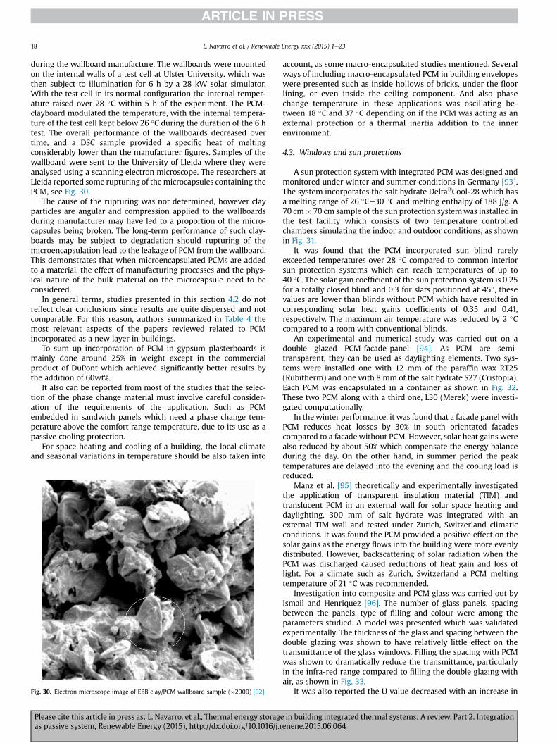
during the wallboard manufacture. The wallboards were mountedon the internal walls of a test cell at Ulster University, which wasthen subject to illumination for 6 h by a 28 kW solar simulator.With the test cell in its normal configuration the internal temper-ature raised over 28 �C within 5 h of the experiment. The PCM-clayboard modulated the temperature, with the internal tempera-ture of the test cell kept below 26 �C during the duration of the 6 htest. The overall performance of the wallboards decreased overtime, and a DSC sample provided a specific heat of meltingconsiderably lower than the manufacturer figures. Samples of thewallboard were sent to the University of Lleida where they wereanalysed using a scanning electron microscope. The researchers atLleida reported some rupturing of themicrocapsules containing thePCM, see Fig. 30.
The cause of the rupturing was not determined, however clayparticles are angular and compression applied to the wallboardsduring manufacturer may have led to a proportion of the micro-capsules being broken. The long-term performance of such clay-boards may be subject to degradation should rupturing of themicroencapsulation lead to the leakage of PCM from the wallboard.This demonstrates that when microencapsulated PCMs are addedto a material, the effect of manufacturing processes and the phys-ical nature of the bulk material on the microcapsule need to beconsidered.
In general terms, studies presented in this section 4.2 do notreflect clear conclusions since results are quite dispersed and notcomparable. For this reason, authors summarized in Table 4 themost relevant aspects of the papers reviewed related to PCMincorporated as a new layer in buildings.
To sum up incorporation of PCM in gypsum plasterboards ismainly done around 25% in weight except in the commercialproduct of DuPont which achieved significantly better results bythe addition of 60wt%.
It also can be reported from most of the studies that the selec-tion of the phase change material must involve careful consider-ation of the requirements of the application. Such as PCMembedded in sandwich panels which need a phase change tem-perature above the comfort range temperature, due to its use as apassive cooling protection.
For space heating and cooling of a building, the local climateand seasonal variations in temperature should be also taken into
account, as some macro-encapsulated studies mentioned. Severalways of including macro-encapsulated PCM in building envelopeswere presented such as inside hollows of bricks, under the floorlining, or even inside the ceiling component. And also phasechange temperature in these applications was oscillating be-tween 18 �C and 37 �C depending on if the PCM was acting as anexternal protection or a thermal inertia addition to the innerenvironment.
4.3. Windows and sun protections
A sun protection systemwith integrated PCM was designed andmonitored under winter and summer conditions in Germany [93].The system incorporates the salt hydrate Delta®Cool-28 which hasa melting range of 26 �Ce30 �C and melting enthalpy of 188 J/g. A70 cm� 70 cm sample of the sun protection systemwas installed inthe test facility which consists of two temperature controlledchambers simulating the indoor and outdoor conditions, as shownin Fig. 31.
It was found that the PCM incorporated sun blind rarelyexceeded temperatures over 28 �C compared to common interiorsun protection systems which can reach temperatures of up to40 �C. The solar gain coefficient of the sun protection system is 0.25for a totally closed blind and 0.3 for slats positioned at 45�, thesevalues are lower than blinds without PCM which have resulted incorresponding solar heat gains coefficients of 0.35 and 0.41,respectively. The maximum air temperature was reduced by 2 �Ccompared to a room with conventional blinds.
An experimental and numerical study was carried out on adouble glazed PCM-facade-panel [94]. As PCM are semi-transparent, they can be used as daylighting elements. Two sys-tems were installed one with 12 mm of the paraffin wax RT25(Rubitherm) and one with 8 mm of the salt hydrate S27 (Cristopia).Each PCM was encapsulated in a container as shown in Fig. 32.These two PCM along with a third one, L30 (Merek) were investi-gated computationally.
In the winter performance, it was found that a facade panel withPCM reduces heat losses by 30% in south orientated facadescompared to a facade without PCM. However, solar heat gains werealso reduced by about 50% which compensate the energy balanceduring the day. On the other hand, in summer period the peaktemperatures are delayed into the evening and the cooling load isreduced.
Manz et al. [95] theoretically and experimentally investigatedthe application of transparent insulation material (TIM) andtranslucent PCM in an external wall for solar space heating anddaylighting. 300 mm of salt hydrate was integrated with anexternal TIM wall and tested under Zurich, Switzerland climaticconditions. It was found the PCM provided a positive effect on thesolar gains as the energy flows into the building were more evenlydistributed. However, backscattering of solar radiation when thePCM was discharged caused reductions of heat gain and loss oflight. For a climate such as Zurich, Switzerland a PCM meltingtemperature of 21 �C was recommended.
Investigation into composite and PCM glass was carried out byIsmail and Henriquez [96]. The number of glass panels, spacingbetween the panels, type of filling and colour were among theparameters studied. A model was presented which was validatedexperimentally. The thickness of the glass and spacing between thedouble glazing was shown to have relatively little effect on thetransmittance of the glass windows. Filling the spacing with PCMwas shown to dramatically reduce the transmittance, particularlyin the infra-red range compared to filling the double glazing withair, as shown in Fig. 33.
It was also reported the U value decreased with an increase inFig. 30. Electron microscope image of EBB clay/PCM wallboard sample (�2000) [92].
L. Navarro et al. / Renewable Energy xxx (2015) 1e2318
Please cite this article in press as: L. Navarro, et al., Thermal energy storage in building integrated thermal systems: A review. Part 2. Integrationas passive system, Renewable Energy (2015), http://dx.doi.org/10.1016/j.renene.2015.06.064
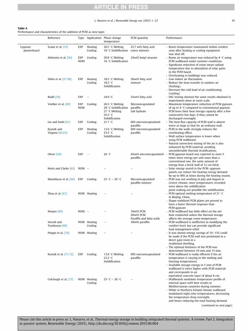
Table 4Performance and characteristics of the addition of PCM as new layer.
Reference Type Application Phase changetemperature
PCM quantity Performance
Gypsumplasterboard
Scalat et al. [55] EXP HeatingCooling
20.5 �C Melting18 �C Solidification
25.7 wt% fatty acidesters mixture
- Room temperature maintained within comfortzone after heating or cooling equipmentwas shut off.
Athientis et al. [56] EXPNUM
Cooling 20.8 �C Melting16 �C Solidification
25wt% butyl stearate - Room air temperature was reduced by 4 �C usingPCM wallboard under summer conditions.
- Significant reduction of room mean radianttemperature due to absorption of solar gainsin the PCM board.
- Overheating in buildings was reduced.Shilei et al. [57,58] EXP Heating
Cooling18.5 �C Melting18.5 �CSolidification
26wt% fatty acidmixture
- Low indoor air fluctuation.- Reduce the heat-transfer to outdoor air(heating).
- Decrease the cold load of air conditioning(cooling)
Rudd [59] EXP e 24.9 �C 25wt% fatty acid - DSC testing showed the same results obtained inexperiments done at room scale.
Voelker et al. [60] EXPNUM
Cooling 26.5 �C Melting28 �C Solidification
Microencapsulatedparaffin
- Maximum temperature reduction of PCM gypsumof up to 4 �C compared to conventional gypsum.
- PCM loses their heat storage capacity after a fewconsecutive hot days, if they cannot bedischarged overnight.
27 �C Melting25.5 �CSolidification
Salt hydrate
Liu and Awbi [61] EXP Cooling 21.7 �C 60% microencapsulatedparaffin
- The heat flux capacity of PCM wall is almosttwice as large as that for an ordinary wall.
Kuznik andVirgone [62,63]
EXP HeatingCooling
13.6 �C Melting23.5 �CSolidification
60% microencapsulatedparaffin
- PCM in the walls strongly reduces theoverheating effect.
- Wall surface temperature is lower whenusing PCM wallboard.
- Natural convection mixing of the air is alsoenhanced by PCM material, avoidinguncomfortable thermal stratifications.
Oliver [64] EXP e 26 �C 45wt% microencapsulatedparaffin
- PCM gypsum board was reported to store 5times more energy per unit mass than aconventional one, the same amount ofenergy than a brick wall of 12 cm thick.
Heim and Clarke [65] NUM e e e - Solar energy stored in the PCMegypsumpanels can reduce the heating energy demandby up to 90% at times during the heating season.
Mandilaras et al. [66] EXP Cooling 23 �C e 26 �C Microencapsulatedparaffin mixture
- PCM was not working in July and August inGreece climate, since temperatures recordedwere above the solidificationpoint making not possible the solidification.
Zhou et al. [67] NUM Heating e e - PCM optimal melting temperature of 21 �Cin Beijing, China.
- Shape-stabilized PCM plates are proved tohave a faster thermal response thanPCM-gypsum
Neeper [68] NUM e e 10wt% PCM20wt% PCMParaffin and fatty acids
- PCM wallboard has little effect on the netheat conducted unless the thermal storageaffects the average room temperature.
Stovall andTomlinson [69]
NUM HeatingCooling
e 30wt% paraffin - PCM-wallboard is ineffective in modifying thecomfort level, but can provide significantload management relief.
Peippo et al. [70] NUM Heating e e - It was shown energy savings of 10e15% couldbe made if the PCM wall was positioned in adirect gain room in aresidential dwelling.
- The optimal thickness of the PCM wasdetermined between 10 mm and 15 mm.
Kuznik et al. [71,72] EXP Cooling 13.6 �C Melting23.5 �CSolidification
60% microencapsulatedparaffin
- PCM wallboard is really efficient if the airtemperature is varying in the melting andfreezing temperatures.
- Available storage energy in 5 mm of PCMwallboard is twice higher with PCM materialand corresponds to anequivalent concrete layer of about 8 cm.
Colclough et al. [73] NUM HeatingCooling
23 �C e 26 �C e - Wallboards modulate temperature profile ofinternal space with best results inMediterranean countries during summer.
- While in Northern Ireland climate wallboardmodulated night time temperatures, decreasingthe temperature drop overnight,and hence reducing the total heating demand.
(continued on next page)
L. Navarro et al. / Renewable Energy xxx (2015) 1e23 19
Please cite this article in press as: L. Navarro, et al., Thermal energy storage in building integrated thermal systems: A review. Part 2. Integrationas passive system, Renewable Energy (2015), http://dx.doi.org/10.1016/j.renene.2015.06.064
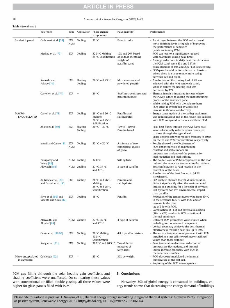
PCM gap filling although the solar heating gain coefficient andshading coefficient were unaffected. On comparing these valueswith conventional air filled double glazing, all three values werehigher for glass panels filled with PCM.
5. Conclusions
Nowadays 30% of global energy is consumed in buildings, en-ergy trends shows that decreasing the energy demand of buildings
Table 4 (continued )
Reference Type Application Phase changetemperature
PCM quantity Performance
Sandwich panel Carbonari et al. [74] EXPNUM
Cooling 32 �C Eutectic salts - An air layer between the PCM and externalmetal finishing layer is capable of improvingthe performance of sandwichpanels containing PCM.
Medina et al. [75] EXP Cooling 32.5 �C Melting25 �C Solidification
10% and 20% basedon indoor sheathingweight ofparaffin-based
- PCM can lead to a significantly reducedwall heat fluxes during peak times.
- Average reductions in daily heat transfer acrossthe PCM-panel were 33% and 38% forconcentrations of 10% and 20% PCM, respectively.
- PCM-panel would perform better in climateswhere there is a large temperature swingbetween day and night.
Konuklu andPaksoy [76]
EXP HeatingCooling
26 �C and 23 �C Microencapsulatedpowdered paraffin
- A reduction on the cooling load of 7% wasachieved with the PCM sandwich panel,while in winter the heating load wasdecreased by 17%.
Castell�on et al. [77] EXP e 26 �C 8wt% microencapsulatedparaffin mixture
- Thermal inertia is increased in cases wherethe PCM is added to during the manufacturingprocess of the sandwich panel.
- While mixing PCM with the polyurethanePCM effect is overlapped by a possibleincrease in thermal conductivity.
MACRO-ENCAPSULATED
Castell et al. [78] EXP Cooling 28 �C and 26 �CMelting26 �C and 25 �CSolidification
Paraffin andsalt hydrates
- Energy consumption of the cooling equipmentwas reduced about 15% in the house-like cubicleswith PCM compared to the ones without PCM.
Zhang et al. [80] EXP HeatingCooling
20 �C e 30 �C 10wt% - 20wt%Paraffin based
- Peak heat fluxes through the PCM frame wallwere substantially reduced when comparedto those through the typical wall.
- Space cooling load was reduced from 8.6 to 10.8%for the 10 and 20% concentrations, respectively.
Ismail and Castro [81] EXPNUM
Cooling 23 �C e 26 �C A mixture of twocommercial gradesof glycol
- Results showed the effectiveness ofPCM-enhanced walls in maintainingconstant and stable indoor airtemperatures and proved the potential forload reduction and load shifting.
Pasupathy andVelraj [82]
NUM Cooling 32.8 �C Salt hydrate - The double layer of PCM incorporated in the roofreduced the indoor air temperature fluctuations.
Alawadhi [83] NUM Cooling 27 �C, 37 �Cand 47 �C
3 type of paraffin - Best configuration is PCM location in thecentreline of the brick.
- A reduction of the heat flux up to 24.2%is registered.
de Gracia et al. [84]and Castell et al. [85]
EXP Cooling 28 �C and 26 �CMelting26 �C and 25 �CSolidification
Paraffin andsalt hydrates
- LCA analysis showed that PCM incorporationdid not significantly affect the environmentalimpact of a building, for a life span of 50 years.
- Salt hydrates had less environmental impactthan paraffin.
Silva et al. [86] andVicente and Silva [87]
EXP Cooling 18 �C Paraffin - Reduction of the temperature swing from 10 �Cin the reference to 5 �C with PCM and anincrease in the timelag of 3 h with PCM.
- Combination of PCM and external insulation(10 cm XPS) resulted in 80% reduction ofthermal amplitude.
Allawadhi andAlqallaf [88]
NUM Cooling 27 �C, 37 �Cand 47 �C
3 type of paraffin - Different PCM geometries were studied whenincluding in concrete roof component.
- Conical geometry achieved the best thermaleffectiveness reducing heat flux up to 39%.
Cer�on et al. [89,90] EXP Cooling 20 �C Melting13.5 �CSolidification
4.8 L paraffin mixture - The surface temperature of pavement with PCMinstalled in a test cell showed more stabilizedvalues than those without.
Kong et al. [91] EXP Cooling 30.2 �C and 26.5 �C Two differentmixtures offatty acids
- Peak temperature decrease, reduction oftemperature fluctuations, and thermalinertia increase especially with PCM inthe inner walls surface.
Micro-encapsulatedin clayboard
Colclough [92] EXP e 23 �C 30% by weight - PCM-clayboard modulated the internaltemperature of the test cell.
- Rupturing of the PCM microcapsules
L. Navarro et al. / Renewable Energy xxx (2015) 1e2320
Please cite this article in press as: L. Navarro, et al., Thermal energy storage in building integrated thermal systems: A review. Part 2. Integrationas passive system, Renewable Energy (2015), http://dx.doi.org/10.1016/j.renene.2015.06.064
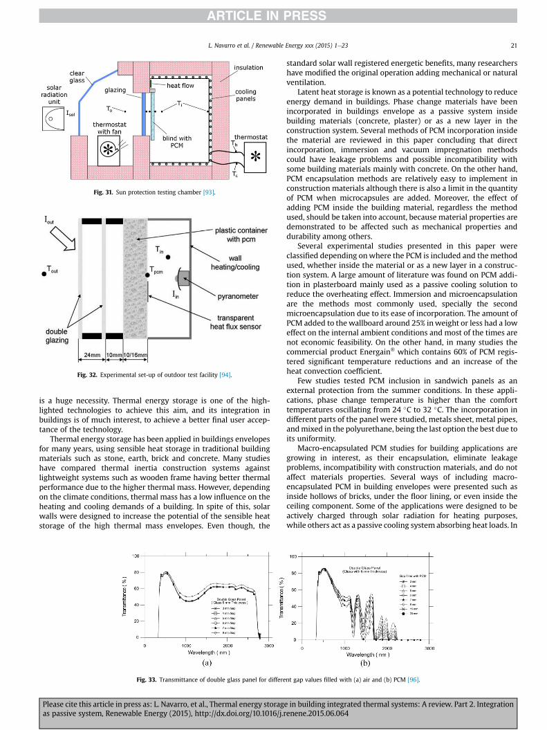
is a huge necessity. Thermal energy storage is one of the high-lighted technologies to achieve this aim, and its integration inbuildings is of much interest, to achieve a better final user accep-tance of the technology.
Thermal energy storage has been applied in buildings envelopesfor many years, using sensible heat storage in traditional buildingmaterials such as stone, earth, brick and concrete. Many studieshave compared thermal inertia construction systems againstlightweight systems such as wooden frame having better thermalperformance due to the higher thermal mass. However, dependingon the climate conditions, thermal mass has a low influence on theheating and cooling demands of a building. In spite of this, solarwalls were designed to increase the potential of the sensible heatstorage of the high thermal mass envelopes. Even though, the
standard solar wall registered energetic benefits, many researchershave modified the original operation adding mechanical or naturalventilation.
Latent heat storage is known as a potential technology to reduceenergy demand in buildings. Phase change materials have beenincorporated in buildings envelope as a passive system insidebuilding materials (concrete, plaster) or as a new layer in theconstruction system. Several methods of PCM incorporation insidethe material are reviewed in this paper concluding that directincorporation, immersion and vacuum impregnation methodscould have leakage problems and possible incompatibility withsome building materials mainly with concrete. On the other hand,PCM encapsulation methods are relatively easy to implement inconstruction materials although there is also a limit in the quantityof PCM when microcapsules are added. Moreover, the effect ofadding PCM inside the building material, regardless the methodused, should be taken into account, because material properties aredemonstrated to be affected such as mechanical properties anddurability among others.
Several experimental studies presented in this paper wereclassified depending onwhere the PCM is included and the methodused, whether inside the material or as a new layer in a construc-tion system. A large amount of literature was found on PCM addi-tion in plasterboard mainly used as a passive cooling solution toreduce the overheating effect. Immersion and microencapsulationare the methods most commonly used, specially the secondmicroencapsulation due to its ease of incorporation. The amount ofPCM added to the wallboard around 25% inweight or less had a loweffect on the internal ambient conditions and most of the times arenot economic feasibility. On the other hand, in many studies thecommercial product Energain® which contains 60% of PCM regis-tered significant temperature reductions and an increase of theheat convection coefficient.
Few studies tested PCM inclusion in sandwich panels as anexternal protection from the summer conditions. In these appli-cations, phase change temperature is higher than the comforttemperatures oscillating from 24 �C to 32 �C. The incorporation indifferent parts of the panel were studied, metals sheet, metal pipes,andmixed in the polyurethane, being the last option the best due toits uniformity.
Macro-encapsulated PCM studies for building applications aregrowing in interest, as their encapsulation, eliminate leakageproblems, incompatibility with construction materials, and do notaffect materials properties. Several ways of including macro-encapsulated PCM in building envelopes were presented such asinside hollows of bricks, under the floor lining, or even inside theceiling component. Some of the applications were designed to beactively charged through solar radiation for heating purposes,while others act as a passive cooling system absorbing heat loads. In
Fig. 32. Experimental set-up of outdoor test facility [94].
Fig. 31. Sun protection testing chamber [93].
Fig. 33. Transmittance of double glass panel for different gap values filled with (a) air and (b) PCM [96].
L. Navarro et al. / Renewable Energy xxx (2015) 1e23 21
Please cite this article in press as: L. Navarro, et al., Thermal energy storage in building integrated thermal systems: A review. Part 2. Integrationas passive system, Renewable Energy (2015), http://dx.doi.org/10.1016/j.renene.2015.06.064
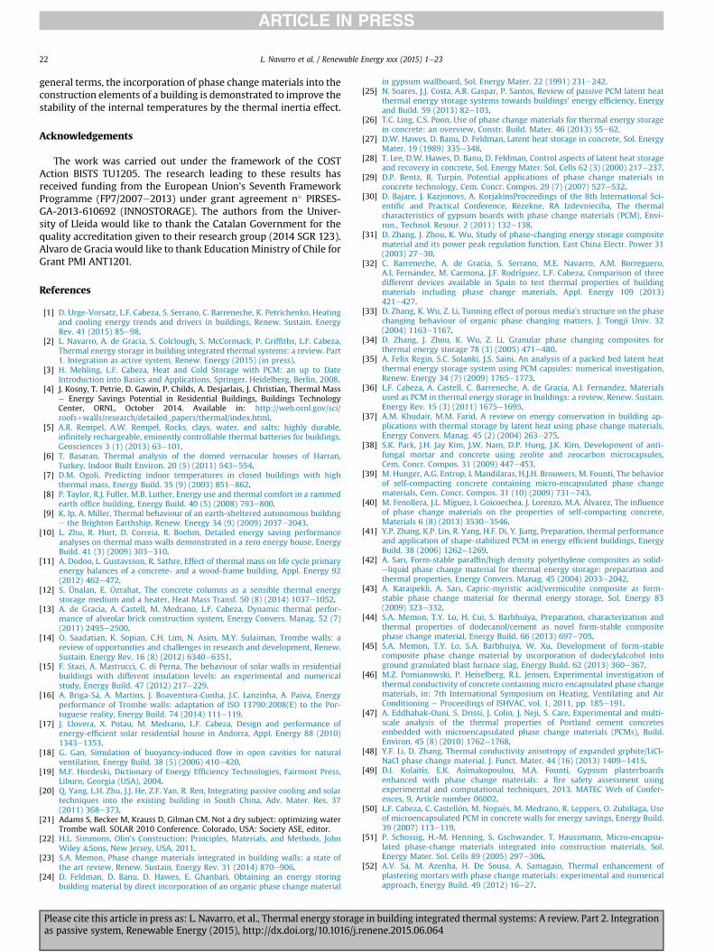
general terms, the incorporation of phase change materials into theconstruction elements of a building is demonstrated to improve thestability of the internal temperatures by the thermal inertia effect.
Acknowledgements
The work was carried out under the framework of the COSTAction BISTS TU1205. The research leading to these results hasreceived funding from the European Union's Seventh FrameworkProgramme (FP7/2007e2013) under grant agreement n� PIRSES-GA-2013-610692 (INNOSTORAGE). The authors from the Univer-sity of Lleida would like to thank the Catalan Government for thequality accreditation given to their research group (2014 SGR 123).Alvaro de Gracia would like to thank Education Ministry of Chile forGrant PMI ANT1201.
References
[1] D. Urge-Vorsatz, L.F. Cabeza, S. Serrano, C. Barreneche, K. Petrichenko, Heatingand cooling energy trends and drivers in buildings, Renew. Sustain. EnergyRev. 41 (2015) 85e98.
[2] L. Navarro, A. de Gracia, S. Colclough, S. McCormack, P. Griffiths, L.F. Cabeza,Thermal energy storage in building integrated thermal systems: a review. Part1. Integration as active system, Renew. Energy (2015) (in press).
[3] H. Mehling, L.F. Cabeza, Heat and Cold Storage with PCM: an up to DateIntroduction into Basics and Applications, Springer, Heidelberg, Berlin, 2008.
[4] J. Kosny, T. Petrie, D. Gawin, P. Childs, A. Desjarlais, J. Christian, Thermal Masse Energy Savings Potential in Residential Buildings, Buildings TechnologyCenter, ORNL, October 2014. Available in: http://web.ornl.gov/sci/roofsþwalls/research/detailed_papers/thermal/index.html.
[5] A.R. Rempel, A.W. Rempel, Rocks, clays, water, and salts: highly durable,infinitely rechargeable, eminently controllable thermal batteries for buildings,Geosciences 3 (1) (2013) 63e101.
[6] T. Basaran, Thermal analysis of the domed vernacular houses of Harran,Turkey, Indoor Built Environ. 20 (5) (2011) 543e554.
[7] D.M. Ogoli, Predicting indoor temperatures in closed buildings with highthermal mass, Energy Build. 35 (9) (2003) 851e862.
[8] P. Taylor, R.J. Fuller, M.B. Luther, Energy use and thermal comfort in a rammedearth office building, Energy Build. 40 (5) (2008) 793e800.
[9] K. Ip, A. Miller, Thermal behaviour of an earth-sheltered autonomous buildinge the Brighton Earthship, Renew. Energy 34 (9) (2009) 2037e2043.
[10] L. Zhu, R. Hurt, D. Correia, R. Boehm, Detailed energy saving performanceanalyses on thermal mass walls demonstrated in a zero energy house, EnergyBuild. 41 (3) (2009) 303e310.
[11] A. Dodoo, L. Gustavsson, R. Sathre, Effect of thermal mass on life cycle primaryenergy balances of a concrete- and a wood-frame building, Appl. Energy 92(2012) 462e472.
[12] S. Ünalan, E. €Ozrahat, The concrete columns as a sensible thermal energystorage medium and a heater, Heat Mass Transf. 50 (8) (2014) 1037e1052.
[13] A. de Gracia, A. Castell, M. Medrano, L.F. Cabeza, Dynamic thermal perfor-mance of alveolar brick construction system, Energy Convers. Manag. 52 (7)(2011) 2495e2500.
[14] O. Saadatian, K. Sopian, C.H. Lim, N. Asim, M.Y. Sulaiman, Trombe walls: areview of opportunities and challenges in research and development, Renew.Sustain. Energy Rev. 16 (8) (2012) 6340e6351.
[15] F. Stazi, A. Mastrucci, C. di Perna, The behaviour of solar walls in residentialbuildings with different insulation levels: an experimental and numericalstudy, Energy Build. 47 (2012) 217e229.
[16] A. Briga-S�a, A. Martins, J. Boaventura-Cunha, J.C. Lanzinha, A. Paiva, Energyperformance of Trombe walls: adaptation of ISO 13790:2008(E) to the Por-tuguese reality, Energy Build. 74 (2014) 111e119.
[17] J. Llovera, X. Potau, M. Medrano, L.F. Cabeza, Design and performance ofenergy-efficient solar residential house in Andorra, Appl. Energy 88 (2010)1343e1353.
[18] G. Gan, Simulation of buoyancy-induced flow in open cavities for naturalventilation, Energy Build. 38 (5) (2006) 410e420.
[19] M.F. Hordeski, Dictionary of Energy Efficiency Technologies, Fairmont Press,Liburn, Georgia (USA), 2004.
[20] Q. Yang, L.H. Zhu, J.J. He, Z.F. Yan, R. Ren, Integrating passive cooling and solartechniques into the existing building in South China, Adv. Mater. Res. 37(2011) 368e373.
[21] Adams S, Becker M, Krauss D, Gilman CM. Not a dry subject: optimizing waterTrombe wall. SOLAR 2010 Conference. Colorado, USA: Society ASE, editor.
[22] H.L. Simmons, Olin's Construction: Principles, Materials, and Methods, JohnWiley &Sons, New Jersey, USA, 2011.
[23] S.A. Memon, Phase change materials integrated in building walls: a state ofthe art review, Renew. Sustain. Energy Rev. 31 (2014) 870e906.
[24] D. Feldman, D. Banu, D. Hawes, E. Ghanbari, Obtaining an energy storingbuilding material by direct incorporation of an organic phase change material
in gypsum wallboard, Sol. Energy Mater. 22 (1991) 231e242.[25] N. Soares, J.J. Costa, A.R. Gaspar, P. Santos, Review of passive PCM latent heat
thermal energy storage systems towards buildings' energy efficiency, Energyand Build. 59 (2013) 82e103.
[26] T.C. Ling, C.S. Poon, Use of phase change materials for thermal energy storagein concrete: an overview, Constr. Build. Mater. 46 (2013) 55e62.
[27] D.W. Hawes, D. Banu, D. Feldman, Latent heat storage in concrete, Sol. EnergyMater. 19 (1989) 335e348.
[28] T. Lee, D.W. Hawes, D. Banu, D. Feldman, Control aspects of latent heat storageand recovery in concrete, Sol. Energy Mater. Sol. Cells 62 (3) (2000) 217e237.
[29] D.P. Bentz, R. Turpin, Potential applications of phase change materials inconcrete technology, Cem. Concr. Compos. 29 (7) (2007) 527e532.
[30] D. Bajare, J. Kazjonovs, A. KorjakinsProceedings of the 8th International Sci-entific and Practical Conference, R�ezekne, RA Izdevniec�ıba, The thermalcharacteristics of gypsum boards with phase change materials (PCM), Envi-ron., Technol. Resour. 2 (2011) 132e138.
[31] D. Zhang, J. Zhou, K. Wu, Study of phase-changing energy storage compositematerial and its power peak regulation function, East China Electr. Power 31(2003) 27e30.
[32] C. Barreneche, A. de Gracia, S. Serrano, M.E. Navarro, A.M. Borreguero,A.I. Fern�andez, M. Carmona, J.F. Rodríguez, L.F. Cabeza, Comparison of threedifferent devices available in Spain to test thermal properties of buildingmaterials including phase change materials, Appl. Energy 109 (2013)421e427.
[33] D. Zhang, K. Wu, Z. Li, Tunning effect of porous media's structure on the phasechanging behaviour of organic phase changing matters, J. Tongji Univ. 32(2004) 1163e1167.
[34] D. Zhang, J. Zhou, K. Wu, Z. Li, Granular phase changing composites forthermal energy storage 78 (3) (2005) 471e480.
[35] A. Felix Regin, S.C. Solanki, J.S. Saini, An analysis of a packed bed latent heatthermal energy storage system using PCM capsules: numerical investigation,Renew. Energy 34 (7) (2009) 1765e1773.
[36] L.F. Cabeza, A. Castell, C. Barreneche, A. de Gracia, A.I. Fernandez, Materialsused as PCM in thermal energy storage in buildings: a review, Renew. Sustain.Energy Rev. 15 (3) (2011) 1675e1695.
[37] A.M. Khudair, M.M. Farid, A review on energy conservation in building ap-plications with thermal storage by latent heat using phase change materials,Energy Convers. Manag. 45 (2) (2004) 263e275.
[38] S.K. Park, J.H. Jay Kim, J.W. Nam, D.P. Hung, J.K. Kim, Development of anti-fungal mortar and concrete using zeolite and zeocarbon microcapsules,Cem. Concr. Compos. 31 (2009) 447e453.
[39] M. Hunger, A.G. Entrop, I. Mandilaras, H.J.H. Brouwers, M. Founti, The behaviorof self-compacting concrete containing micro-encapsulated phase changematerials, Cem. Concr. Compos. 31 (10) (2009) 731e743.
[40] M. Fenollera, J.L. Míguez, I. Goicoechea, J. Lorenzo, M.A. �Alvarez, The influenceof phase change materials on the properties of self-compacting concrete,Materials 6 (8) (2013) 3530e3546.
[41] Y.P. Zhang, K.P. Lin, R. Yang, H.F. Di, Y. Jiang, Preparation, thermal performanceand application of shape-stabilized PCM in energy efficient buildings, EnergyBuild. 38 (2006) 1262e1269.
[42] A. Sarı, Form-stable paraffin/high density polyethylene composites as solid-eliquid phase change material for thermal energy storage: preparation andthermal properties, Energy Convers. Manag. 45 (2004) 2033e2042.
[43] A. Karaipekli, A. Sarı, Capric-myristic acid/vermiculite composite as form-stable phase change material for thermal energy storage, Sol. Energy 83(2009) 323e332.
[44] S.A. Memon, T.Y. Lo, H. Cui, S. Barbhuiya, Preparation, characterization andthermal properties of dodecanol/cement as novel form-stable compositephase change material, Energy Build. 66 (2013) 697e705.
[45] S.A. Memon, T.Y. Lo, S.A. Barbhuiya, W. Xu, Development of form-stablecomposite phase change material by incorporation of dodecylalcohol intoground granulated blast furnace slag, Energy Build. 62 (2013) 360e367.
[46] M.Z. Pomianowski, P. Heiselberg, R.L. Jensen, Experimental investigation ofthermal conductivity of concrete containing micro encapsulated phase changematerials, in: 7th International Symposium on Heating, Ventilating and AirConditioning e Proceedings of ISHVAC, vol. 1, 2011, pp. 185e191.
[47] A. Eddhahak-Ouni, S. Drissi, J. Colin, J. Neji, S. Care, Experimental and multi-scale analysis of the thermal properties of Portland cement concretesembedded with microencapsulated phase change materials (PCMs), Build.Environ. 45 (8) (2010) 1762e1768.
[48] Y.F. Li, D. Zhang, Thermal conductivity anisotropy of expanded grphite/LiCl-NaCl phase change material, J. Funct. Mater. 44 (16) (2013) 1409e1415.
[49] D.I. Kolaitis, E.K. Asimakopoulou, M.A. Founti, Gypsum plasterboardsenhanced with phase change materials: a fire safety assessment usingexperimental and computational techniques, 2013. MATEC Web of Confer-ences, 9, Article number 06002.
[50] L.F. Cabeza, C. Castell�on, M. Nogu�es, M. Medrano, R. Leppers, O. Zubillaga, Useof microencapsulated PCM in concrete walls for energy savings, Energy Build.39 (2007) 113e119.
[51] P. Schossig, H.-M. Henning, S. Gschwander, T. Haussmann, Micro-encapsu-lated phase-change materials integrated into construction materials, Sol.Energy Mater. Sol. Cells 89 (2005) 297e306.
[52] A.V. S�a, M. Azenha, H. De Sousa, A. Samagaio, Thermal enhancement ofplastering mortars with phase change materials: experimental and numericalapproach, Energy Build. 49 (2012) 16e27.
L. Navarro et al. / Renewable Energy xxx (2015) 1e2322
Please cite this article in press as: L. Navarro, et al., Thermal energy storage in building integrated thermal systems: A review. Part 2. Integrationas passive system, Renewable Energy (2015), http://dx.doi.org/10.1016/j.renene.2015.06.064
[53] A.C. Evers, M.A. Medina, Y. Fang, Evaluation of the thermal performance offrame walls enhanced with paraffin and hydrated salt phase change materialsusing a dynamic wall simulator, Build. Environ. 45 (2010) 1762e1768.
[54] J. Kosny, E. Kossecka, A. Brzezinski, A. Tleoubaev, D. Yarbrough, Dynamicthermal performance analysis of fiber insulations containing bio-based phasechange materials (PCMs), Energy Build. 52 (2012) 122e131.
[55] S. Scalat, D. Banu, D. Hawes, J. Paris, F. Haghighat, D. Feldman, Full scalethermal testing of latent heat storage in wallboard, Sol. Energy Mater. Sol.Cells 44 (1996) 46e61.
[56] A.K. Athienitis, C. Liu, D. Hawes, D. Banu, D. Feldman, Investigation of thethermal performance of a passive solar test-room with wall latent heatstorage, Build. Environ. 32 (1997) 405e410.
[57] L. Shilei, Z. Neng, F. Guohui, Impact of phase change wall room on indoorthermal environment in winter, Energy Build. 38 (1) (2006) 18e24.
[58] L. Shilei, F. Guohui, Z. Neng, D. Li, Experimental study and evaluation of latentheat storage in phase change materials wallboards, Energy Build. 39 (10)(2007) 1088e1091.
[59] A.F. Rudd, Phase change material wallboard for distributes thermal storage inbuildings, ASHRAE 99 (2) (1993) 339e346.
[60] C. Voelker, O. Kornadt, M. Ostry, Temperature reduction due to the applicationof phase change materials, Energy Build. 40 (2008) 937e944.
[61] H. Liu, H.B. Awbi, Performance of phase change material boards under naturalconvection, Build. Environ. 44 (9) (2009) 1788e1793.
[62] F. Kuznik, J. Virgone, Experimental assessment of phase change material forwall building use, Appl. Energy 86 (2009) 2038e2046.
[63] F. Kuznik, J. Virgone, Experimental investigation of wallboard containingphase change material: data for validation of numerical modelling, EnergyBuild. 41 (2009) 561e570.
[64] A. Oliver, Thermal characterization of gypsum boards with PCM included:thermal energy storage in buildings through latent heat, Energy Build. 48(2012) 1e7.
[65] D. Heim, J.A. Clarke, Numerical modelling and thermal simulation of PCM-gypsum composites with ESP-r, Energy Build. 36 (2004) 795e805.
[66] I. Mandilaras, M. Stamatiadou, D. Katsourinis, G. Zannis, M. Founti, Experi-mental thermal characterisation of a Mediterranean residential building withPCM gypsum board walls, Build. Environ. 61 (2013) 93e103.
[67] G. Zhou, Y. Zhang, X. Wang, K. Lin, W. Xiao, An assessment of mixed typePCM-gypsum and shape stabilised PCM plates in a building for passive solarheating, Sol. Energy 81 (2007) 1351e1360.
[68] D.A. Neeper, Thermal dynamics of wallboard with latent heat storage, Sol.Energy 68 (2000) 393e403.
[69] T.K. Stovall, J.J. Tomlinson, What are the potential benefits of including latentheat storage in common wall board, Trans. ASME 117 (1995) 318e325.
[70] K. Peippo, P. Kauranen, P.D. Lund, A multi-component pcm wall optimized forpassive solar heating, Energy Build. 17 (1991) 259e270.
[71] F. Kuznik, J. Virgone, K. Johannes, In-situ study of thermal comfort enhance-ment in a renovated building equipped with phase change material wall-board, Renew. Energy 36 (5) (2011) 1458e1462.
[72] F. Kuznik, J. Virgone, J.J. Roux, Energetic efficiency of room wall containingPCM wallboard: a full-scale experimental investigation, Energy Build. 40 (2)(2008) 148e156.
[73] S.M. Colclough, P.W. Griffiths, M.G. Smyth, in: Thermal Energy Storage and thePassive House Standard: How PCM Incorporated into Wallboard Can AidThermal Comfort, PLEA Conference, Montreal, Quebec, Canada, 2009.
[74] A. Carbonari, M.D. Grassi, C.D. Perna, P. Principi, Numerical and experimentalanalyses of PCM containing sandwich panels for prefabricated walls, EnergyBuild. 38 (2006) 472e483.
[75] M. Medina, J. King, M. Zhang, On the heat transfer rate reduction of structuralinsulated panels (SIPs) outfitted with phase change materials (PCMs), Energy33 (4) (2008) 667e678.
[76] Y. Konuklu, H.O. Paksoy, Phase change material sandwich panels for managingsolar gain in buildings, J. Sol. Energy Eng. Trans. ASME 131 (4) (2009)0410121e0410127.
[77] C. Castell�on, M. Medrano, J. Roca, L.F. Cabeza, M.E. Navarro, A.I. Fern�andez,A. L�azaro, B. Zalba, Effect of microencapsulated phase change material insandwich panels, Renew. Energy 35 (2010) 2370e2374.
[78] A. Castell, I. Martorell, M. Medrano, G. P�erez, L.F. Cabeza, Experimental studyof using PCM in brick constructive solutions for passive cooling, Energy Build.42 (2010) 534e540.
[79] Rubitherm. Available in: http://www.rubitherm.de/english/index.htm(October 2014).
[80] M. Zhang, M.A. Medina, J.B. King, Development of a thermally enhanced framewall with phase change materials for on-peak air conditioning demandreduction and energy savings in residential buildings, Int. J. Energy Res. 29(2005) 795e809.
[81] K.A.R. Ismail, J.N.C. Castro, PCM thermal insulation in buildings, Int. J. EnergyRes. 21 (1997) 1281e1296.
[82] A. Pasupathy, R. Velraj, Effect of double layer phase change material inbuilding roof for year round thermal management, Energy Build. 40 (2008)193e203.
[83] E.M. Alawadhi, Thermal analysis of a building brick containing phase changematerial, Energy Build. 40 (2008) 351e357.
[84] A. de Gracia, L. Rinc�on, A. Castell, M. Jim�enez, D. Boer, M. Medrano, L.F. Cabeza,Life Cycle Assessment of the inclusion of phase change materials (PCM) inexperimental buildings, Energy Build. 42 (2010) 1517e1523.
[85] A. Castell, K. Menoufi, A. de Gracia, L. Rinc�on, D. Boer, L.F. Cabeza, Life CycleAssessment of alveolar brick construction system incorporating phase changematerials (PCMs), Appl. Energy 101 (2013) 600e608.
[86] T. Silva, R. Vicente, N. Soares, V. Ferreira, Experimental testing and numericalmodelling of masonry wall solution with PCM incorporation: a passive con-struction solution, Energy Build. 49 (2012) 235e245.
[87] R. Vicente, T. Silva, Brick masonry walls with PCM macrocapsules: an exper-imental approach, Appl. Therm. Eng. 67 (2014) 24e34.
[88] E.M. Alawadhi, H.J. Alqallaf, Building roof with conical holes containing PCMto reduce the cooling load: numerical study, Energy Convers. Manag. 52(2011) 2958e2964.
[89] I. Cer�on, J. Neila, M. Khayet, Experimental tile with phase change materials(PCM) for building use, Energy Build. 43 (2011) 1869e1874.
[90] Latipat F. Pavimento acondicionador termico para interiores patent 2010, no
ES2333092.[91] X. Kong, S. Lu, J. Huang, Z. Cai, S. Wei, Experimental research on the use of
phase change materials in perforated brick rooms for cooling storage, EnergyBuild. 62 (2013) 597e604.
[92] Colclough S, Thermal energy storage applied to the Passivhaus standard in theIrish Climate, (PhD theis), University of Ulster.
[93] H. Weinlaeder, W. Koerner, M. Heidenfelder, Monitoring results of an interiorsun protection system with integrated latent heat storage, Energy Build. 43(9) (2011) 2468e2475.
[94] H. Weinl€ader, A. Beck, J. Fricke, PCM-facade-panel for daylighting and roomheating, Sol. Energy 78 (2) (2005) 177e186.
[95] H. Manz, P.W. Egolf, P. Suter, A. Goetzberger, TIM-PCM external wall systemfor solar space heating and daylighting, Sol. Energy 61 (6) (1997) 369e379.
[96] K.A.R. Ismail, J.R. Henriquez, Parametric study on composite and PCM glasssystems, Energy Convers. Manag. 43 (7) (2002) 973e993.
L. Navarro et al. / Renewable Energy xxx (2015) 1e23 23
Please cite this article in press as: L. Navarro, et al., Thermal energy storage in building integrated thermal systems: A review. Part 2. Integrationas passive system, Renewable Energy (2015), http://dx.doi.org/10.1016/j.renene.2015.06.064