Embed Size (px)
Citation preview

Brodogradnja/Shipbuilding/Open access Volume 67 Number 4, 2017
17
Lech Murawski
http://dx.doi.org/10.21278/brod67402 ISSN 0007-215X
eISSN 1845-5859
THERMAL DISPLACEMENT
OF CRANKSHAFT AXIS OF SLOW-SPEED MARINE ENGINE
UDC 629.5(05):621.436
Original scientific paper
Summary
The paper presents analysis of displacement of a crankshaft axis caused by temperature
of marine, slow-speed main engine. Information of thermal displacement of a power
transmission system axis is significant during a shaft line alignment and a crankshaft springing
analysis. Warmed-up main engine is a source of deformations of an engine body as well as a
ship hull in the area of an engine room and hence axis of a crankshaft and a shaftline. Engines'
producers recommend the model of parallel displacement of the crankshaft axis under the
influence of an engine heat. The model gives us the value (one number!) of the crankshaft axis
displacement in the hot propulsion system's condition. This model may be too simple in some
cases. Presented numerical analyses are based on temperature measurements of the main engine
body and the ship hull during a sea voyage. The paper presents computations of MAN B&W
K98MC type engine (power: 40000 kW, revolutions: 94 rpm) mounted on 4500 TEU container
ship (length: 290 m). Propulsion system is working in nominal, steady-state conditions; it is the
basic assumption during the analyses. Numerical analyses were preformed with usage of
Nastran software based on Finite Element Method. The FEM model of the engine body
comprised over 800 thousand degree of freedom. Stiffness of the ship hull (mainly double
bottom) with the foundation was modelled by a simple cuboid. Material properties of that
cuboid were determined on the base of separately performed calculations.
Key words: temperature deformation; marine propulsion system; shaftline alignment;
crankshaft springing; slow-speed main engine
1. Introduction
Proper shaftline alignment is one of the most important procedures during marine
propulsion system designing, installation and exploitation. The axis of journal bearings of
shaftline should be displaced (mainly in vertical direction) to the proper position [1, 2, 3].
Usually, the crankshaft axis is a baseline for shaftline alignment. Even bearings loads and
proper interaction between a shaftline and a crankshaft is the aim of this procedure.
Measurements of crankshaft springing give information about the proper engine foundation as
well as the proper loads coming from shaftline. During the shaftline alignment and crankshaft
springing analyses, knowledge of the thermal displacement of the crankshaft axis is essential.
Lech Murawski Thermal displacement of crankshaft axis of slow-speed marine engine
18
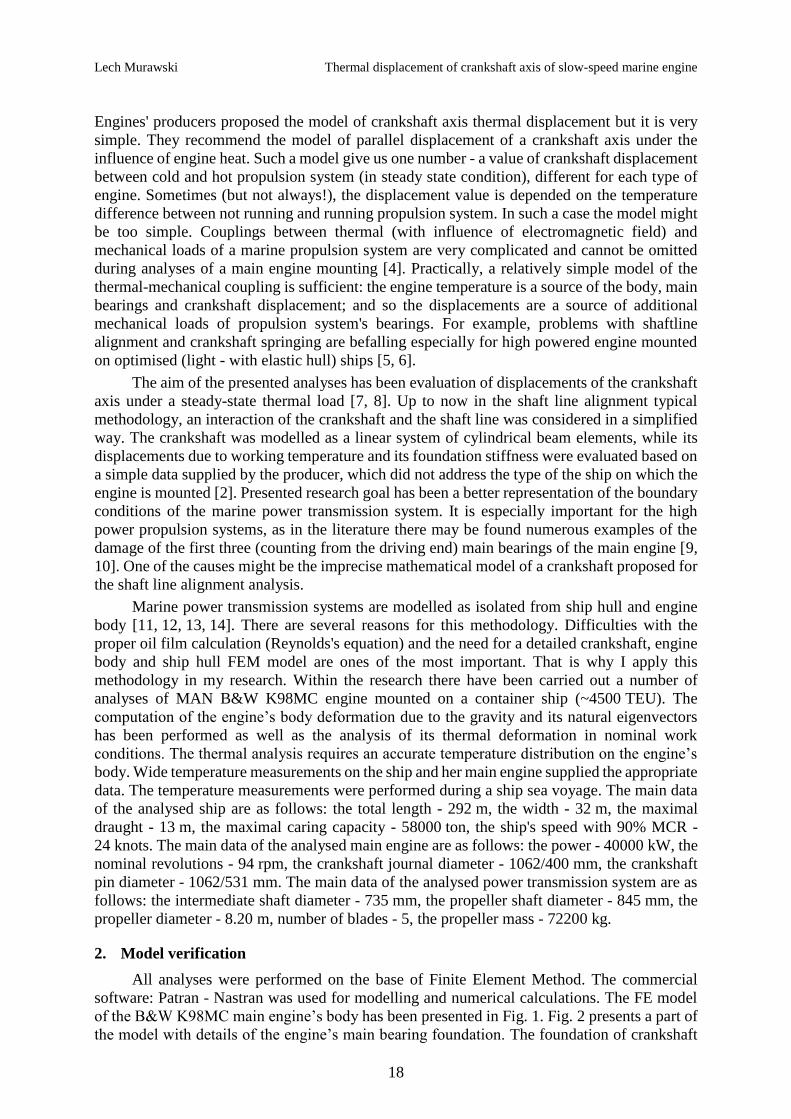
Engines' producers proposed the model of crankshaft axis thermal displacement but it is very
simple. They recommend the model of parallel displacement of a crankshaft axis under the
influence of engine heat. Such a model give us one number - a value of crankshaft displacement
between cold and hot propulsion system (in steady state condition), different for each type of
engine. Sometimes (but not always!), the displacement value is depended on the temperature
difference between not running and running propulsion system. In such a case the model might
be too simple. Couplings between thermal (with influence of electromagnetic field) and
mechanical loads of a marine propulsion system are very complicated and cannot be omitted
during analyses of a main engine mounting [4]. Practically, a relatively simple model of the
thermal-mechanical coupling is sufficient: the engine temperature is a source of the body, main
bearings and crankshaft displacement; and so the displacements are a source of additional
mechanical loads of propulsion system's bearings. For example, problems with shaftline
alignment and crankshaft springing are befalling especially for high powered engine mounted
on optimised (light - with elastic hull) ships [5, 6].
The aim of the presented analyses has been evaluation of displacements of the crankshaft
axis under a steady-state thermal load [7, 8]. Up to now in the shaft line alignment typical
methodology, an interaction of the crankshaft and the shaft line was considered in a simplified
way. The crankshaft was modelled as a linear system of cylindrical beam elements, while its
displacements due to working temperature and its foundation stiffness were evaluated based on
a simple data supplied by the producer, which did not address the type of the ship on which the
engine is mounted [2]. Presented research goal has been a better representation of the boundary
conditions of the marine power transmission system. It is especially important for the high
power propulsion systems, as in the literature there may be found numerous examples of the
damage of the first three (counting from the driving end) main bearings of the main engine [9,
10]. One of the causes might be the imprecise mathematical model of a crankshaft proposed for
the shaft line alignment analysis.
Marine power transmission systems are modelled as isolated from ship hull and engine
body [11, 12, 13, 14]. There are several reasons for this methodology. Difficulties with the
proper oil film calculation (Reynolds's equation) and the need for a detailed crankshaft, engine
body and ship hull FEM model are ones of the most important. That is why I apply this
methodology in my research. Within the research there have been carried out a number of
analyses of MAN B&W K98MC engine mounted on a container ship (~4500 TEU). The
computation of the engine’s body deformation due to the gravity and its natural eigenvectors
has been performed as well as the analysis of its thermal deformation in nominal work
conditions. The thermal analysis requires an accurate temperature distribution on the engine’s
body. Wide temperature measurements on the ship and her main engine supplied the appropriate
data. The temperature measurements were performed during a ship sea voyage. The main data
of the analysed ship are as follows: the total length - 292 m, the width - 32 m, the maximal
draught - 13 m, the maximal caring capacity - 58000 ton, the ship's speed with 90% MCR -
24 knots. The main data of the analysed main engine are as follows: the power - 40000 kW, the
nominal revolutions - 94 rpm, the crankshaft journal diameter - 1062/400 mm, the crankshaft
pin diameter - 1062/531 mm. The main data of the analysed power transmission system are as
follows: the intermediate shaft diameter - 735 mm, the propeller shaft diameter - 845 mm, the
propeller diameter - 8.20 m, number of blades - 5, the propeller mass - 72200 kg.
2. Model verification
All analyses were performed on the base of Finite Element Method. The commercial
software: Patran - Nastran was used for modelling and numerical calculations. The FE model
of the B&W K98MC main engine’s body has been presented in Fig. 1. Fig. 2 presents a part of
the model with details of the engine’s main bearing foundation. The foundation of crankshaft

Thermal displacement of crankshaft axis of slow-speed marine engine Lech Murawski
19
in the main bearings is the most important region in the presented type of analysis. FEM model
of main bearings is realised by 3-D solid elements (8-nodes), the rest part of engine body is
modelled by 4-node plate elements. The whole FEM model of the engine’ body has over 812
thousands degrees of freedom and over 170 thousands elements. Engine model is 8 times (!)
greater than model of the ship hull (see Fig. 3). It is the main reason for separate calculations
of the engine temperature deformations and the ship hull stiffness.
Fig. 1. Model of the main engine body
Fig. 2. Details of the engine’s main bearing foundation
The detailed model of the engine body has to be analysed as separated from the ship hull.
Three types of engine foundation model (boundary conditions) were analysed. First one is
classical - known from literature: foundation arms are completely blocked (fixed deformation).
In the second way the ship hull stiffness was modelled by beam elements. This method does
not take into account couplings between supporting points of the ship hull (the ship hull is
treated as a continuous beam). In the third method the foundation arms are modelled by
continuous cuboid (with the cross section 0.468x0.5 m) with special material properties. On the
base of the separate analyses, the stiffness of the ship hull in the engine room area (with the
Lech Murawski Thermal displacement of crankshaft axis of slow-speed marine engine
20
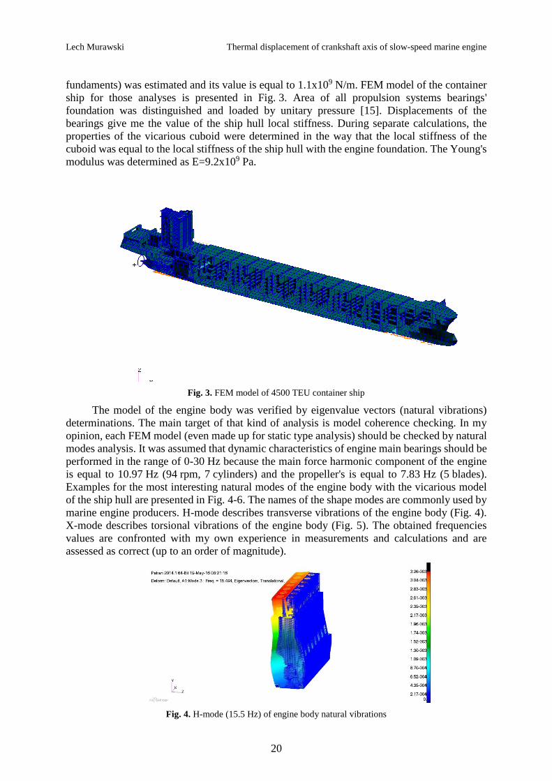
fundaments) was estimated and its value is equal to 1.1x10⁹ N/m. FEM model of the container
ship for those analyses is presented in Fig. 3. Area of all propulsion systems bearings'
foundation was distinguished and loaded by unitary pressure [15]. Displacements of the
bearings give me the value of the ship hull local stiffness. During separate calculations, the
properties of the vicarious cuboid were determined in the way that the local stiffness of the
cuboid was equal to the local stiffness of the ship hull with the engine foundation. The Young's
modulus was determined as E=9.2x10⁹ Pa.
Fig. 3. FEM model of 4500 TEU container ship
The model of the engine body was verified by eigenvalue vectors (natural vibrations)
determinations. The main target of that kind of analysis is model coherence checking. In my
opinion, each FEM model (even made up for static type analysis) should be checked by natural
modes analysis. It was assumed that dynamic characteristics of engine main bearings should be
performed in the range of 0-30 Hz because the main force harmonic component of the engine
is equal to 10.97 Hz (94 rpm, 7 cylinders) and the propeller's is equal to 7.83 Hz (5 blades).
Examples for the most interesting natural modes of the engine body with the vicarious model
of the ship hull are presented in Fig. 4-6. The names of the shape modes are commonly used by
marine engine producers. H-mode describes transverse vibrations of the engine body (Fig. 4).
X-mode describes torsional vibrations of the engine body (Fig. 5). The obtained frequencies
values are confronted with my own experience in measurements and calculations and are
assessed as correct (up to an order of magnitude).
Fig. 4. H-mode (15.5 Hz) of engine body natural vibrations

Thermal displacement of crankshaft axis of slow-speed marine engine Lech Murawski
21
Fig. 5. X-mode (25.3 Hz) of engine body natural vibrations
Fig. 6. Mode (30.6 Hz) of main bearings foundation natural vibrations
Values of natural frequencies for each type of boundary conditions (the modelling method
of the ship hull and the engine foundation) were compared. While the boundary conditions have
not very important influence on natural frequencies of the main bearings foundations, these
conditions affect the global engine eigenvalues very much. The modelling method of the
boundary conditions (the ship hull stiffness with the engine foundation) is essential during
engine body analyses. Fixed nodes in the foundation arms area give us too stiff model but hull
stiffness modelled by beams gives us too elastic model (because of not taking into account
couplings between hull areas). The values of calculated natural vibration frequencies are shown
in table 1. Model with cuboid foundation is the best and it is consistent with author's experience
(comparison with measurements onboard of typical main engine body natural frequencies).
During further calculations cuboid model will be analysed. On the base of natural vibrations
analyses it may be observed that stiffness of the engine body (especially of the main bearings
foundations) is high. It is much higher than primary excitation frequencies of propulsion
system. Therefore, the dynamic stiffness of the engine bearings is not much different to the
static stiffness.

Lech Murawski Thermal displacement of crankshaft axis of slow-speed marine engine
22
Table 1 Natural vibration frequencies of the main engine body
Type of
mode
The ship hull stiffness
not modelled (fixed
displacement)
The ship hull stiffness
modelled by beam
elements
The ship hull stiffness
modelled by
continuous cuboid
H 22.6 Hz 12.4 Hz 15.5 Hz
X 31.3 Hz 24.1 Hz 25.3 Hz
Mode of
main
bearings
foundation
31.4 Hz 29.1 Hz 30.6 Hz
3. Temperature distribution of engine body
Before the start of the thermal deformation analysis of the engine body it is necessary to
determine the engine temperature distribution. The temperature map has been created on the
basis of the measurements carried out on a marine main engine during sea trials. The
temperature determination on the base of measurements is much more accurate in comparison
to calculation analysis of heat transfer. Calculation has to be based on several values which are
difficult for determination, e.g. the power of heat source, the temperatures of oil and cooling
water, and the coefficients of heat transfer. The engine load was under stable parameters of
nominal working condition. The meter used for measurement was pyrometer made by Alfa-
Tech type Rytek MT 4. The temperature was measured in 60 points located around whole
engine body. Ten points were located regularly around the cylinder heads; twenty points were
located regularly on each lateral side of the engine body and ten points were located regularly
on the fore and aft sides of the engine body. There is a big difference between cylinder heads
and other part of engine body. The temperature distribution was estimated (with using linear
interpolation between measured points) and included in the numerical model. The temperature
distribution of cylinder heads and other part of the engine body is presented in Fig. 7 and Fig.
8.
Fig. 7. Temperature distribution measured on cylinder heads
Thermal displacement of crankshaft axis of slow-speed marine engine Lech Murawski
23
Fig. 8. Temperature distribution measured on engine body
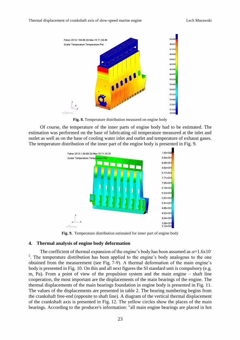
Of course, the temperature of the inner parts of engine body had to be estimated. The
estimation was performed on the base of lubricating oil temperature measured at the inlet and
outlet as well as on the base of cooling water inlet and outlet and temperature of exhaust gases.
The temperature distribution of the inner part of the engine body is presented in Fig. 9.
Fig. 9. Temperature distribution estimated for inner part of engine body
4. Thermal analysis of engine body deformation
The coefficient of thermal expansion of the engine’s body has been assumed as =1.6x10-
5. The temperature distribution has been applied to the engine’s body analogous to the one
obtained from the measurement (see Fig. 7-9). A thermal deformation of the main engine’s
body is presented in Fig. 10. On this and all next figures the SI standard unit is compulsory (e.g.
m, Pa). From a point of view of the propulsion system and the main engine – shaft line
cooperation, the most important are the displacements of the main bearings of the engine. The
thermal displacements of the main bearings foundation in engine body is presented in Fig. 11.
The values of the displacements are presented in table 2. The bearing numbering begins from
the crankshaft free-end (opposite to shaft line). A diagram of the vertical thermal displacement
of the crankshaft axis is presented in Fig. 12. The yellow circles show the places of the main
bearings. According to the producer's information: "all main engine bearings are placed in hot

Lech Murawski Thermal displacement of crankshaft axis of slow-speed marine engine
24
condition higher than in cold condition". Total vertical thermal displacement of the engine
bearings in hot condition, when comparing with cold condition, is equal to: he=0.37 mm -
according to MAN B&W drawing No. 0793023-4, when the engine temperature is raised from
cold (20C) to normal running temperature (55C).
Fig. 10. Engine body deformation under heating influence
Fig. 11. The main bearings foundation displacement under the heat influence
Table 2 Thermal Displacements of the Main Bearings of MAN B&W K98MC Engine
Main
Bearing
No.
Vertical Displacement
[mm]
Horizontal
Displacement
[mm]
Axial Displacement
[mm]
1 0.080 0.067 -1.835
2 0.421 0.011 -1.181
3 0.591 0.007 -0.718
4 0.671 0.019 -0.337
5 0.697 0.031 0.036
6 0.651 0.065 0.432
7 0.551 0.063 0.771
8 0.404 0.048 1.622
9 0.099 0.021 1.601

Thermal displacement of crankshaft axis of slow-speed marine engine Lech Murawski
25
Fig. 12. Diagram of thermal vertical displacement of crankshaft axis
The numerically computed (tab. 2) average value of the translation of the crankshaft's
axis (0.46 mm) is greater than the one recommended by the producer (0.37 mm). The difference
is not particularly big (bellow 20%), but the displacement is of a hogging type. It seems that the
producer’s assumption about the parallel translation of the crankshaft’s axis is incorrect. The
hogging type deformation of the crankshaft results can have significant influence on the
moment load coming from the shaft line. The effect seems to be considerable in the precise
shaft line alignment analysis. Presented conclusion should be treated with caution because the
thermal deformation of ship hull is not taken into account. Heat is flowing from the engine to
the ship hull and locally it may be a source of other deformation of engine foundation. An
analysis of the temperature deformation of ship hull in the engine room area is planned by the
author.
Horizontal deformations of the crankshaft axis under the heating are negligible, in spite
of the temperature differences between left and right sides of the engine body. This is in
accordance with the marine engines manufacturers' recommendations. They recommend that
the shaft line alignment is performed only in vertical plane.
5. Influence of crankshaft axis thermal deformation on shaft line alignment and
crankshaft springing
Influence of crankshaft axis thermal deformation on shaft line alignment was analysed
with usage of author's specialized software [15, 16]. The software is based on finite element
method. The main advantages of the software are: modeling of stern tube bearing as a
continuous support and taking into account elasticity of propulsion system foundation. Several
calculations were performed for the analysed propulsion system accounting for the analyses of
the oil film distribution (non-linear Reynolds equation) in the sliding bearings (especially the
stern tube bearing with a variable clearance) [17]. Finally, two models (results) were compared:
with crankshaft axis thermal deformation recommended by the engine's producer and the other
one determined on the base of the analysis presented in chapter 4. An example of the shaft line
alignment analyses (the deformation and the bending moments and shear forces distribution)
performed by the author are presented in Fig. 13 and 14. Two values of shaft line deformation
(Fig. 13) are important. First one: absolute linear deformation (left axis) given usually in
millimeters; and second one: angular deformation - shaft line rotation, given in shipyards
practice in millimeters per meters (right axis). Both results have been achieved for the most
complicated model with the numerically estimated stiffnesses of the propulsion system [18] and
the thermal deformations.
Position along ME

Lech Murawski Thermal displacement of crankshaft axis of slow-speed marine engine
26
Fig. 13. Shaft line deformation after taking into account the actual thermal deformation of the crankshaft axis
Fig. 14. Shaft line bending moments and shear forces distribution after taking into account the actual thermal
deformation of the crankshaft axis
Taking into consideration detailed thermal deformation of crankshaft axis has not big
influence on calculation results of global parameters of shaft line alignment. The Fig. 13 and
Fig. 14 correspond to the inclusion of the thermal load deformations. The analogous curves for
the case of neglecting this deformation look qualitatively similar. The quantitative differences
between both cases are as follows. Maximal bending stress was changed by 2.2%. Shaft line
bearings' (except the fore intermediate bearing) reactions value was changed less than 9%. But
the hogging type of the thermal deformation of the crankshaft axis has big influence on the
mutual loading between the crankshaft and the shaft line. The reaction of the fore intermediate
bearing (closest to the crankshaft) was changed by 24% (bearing loading was increased by
64 kN). Also, loadings of first three main bearings of crankshaft were changed significantly.
Main bearing No. 1 was relieved by 173 kN (71%), No. 2 was more loaded by 27 kN (10%)
and No. 3 was also more loaded by 96 kN (23%). Other main bearings are not sensitive to model
changes. Also, bending moment and shear force acting on crankshaft flange was changed
significantly. Discussed values of the shaft line alignment are presented in table 3.
Angular deformation
Linear deformation
Bending moments
Shear forces
Thermal displacement of crankshaft axis of slow-speed marine engine Lech Murawski
27
Table 3 The most important influences of the crankshaft thermal displacement on the shaft line alignment
parameters
Cold main engine Hot main engine
Reaction of the fore
intermediate bearing 271 kN 331 kN
Reaction of the main
bearing No. 1 244 kN 71 kN
Reaction of the main
bearing No. 2 268 kN 295 kN
Reaction of the main
bearing No. 3 421 kN 517 kN
Bending moment on the
flange of the crankshaft 53.0 kNm 58.5 kNm
Shear force on the flange
of the crankshaft 134 kN 148 kN
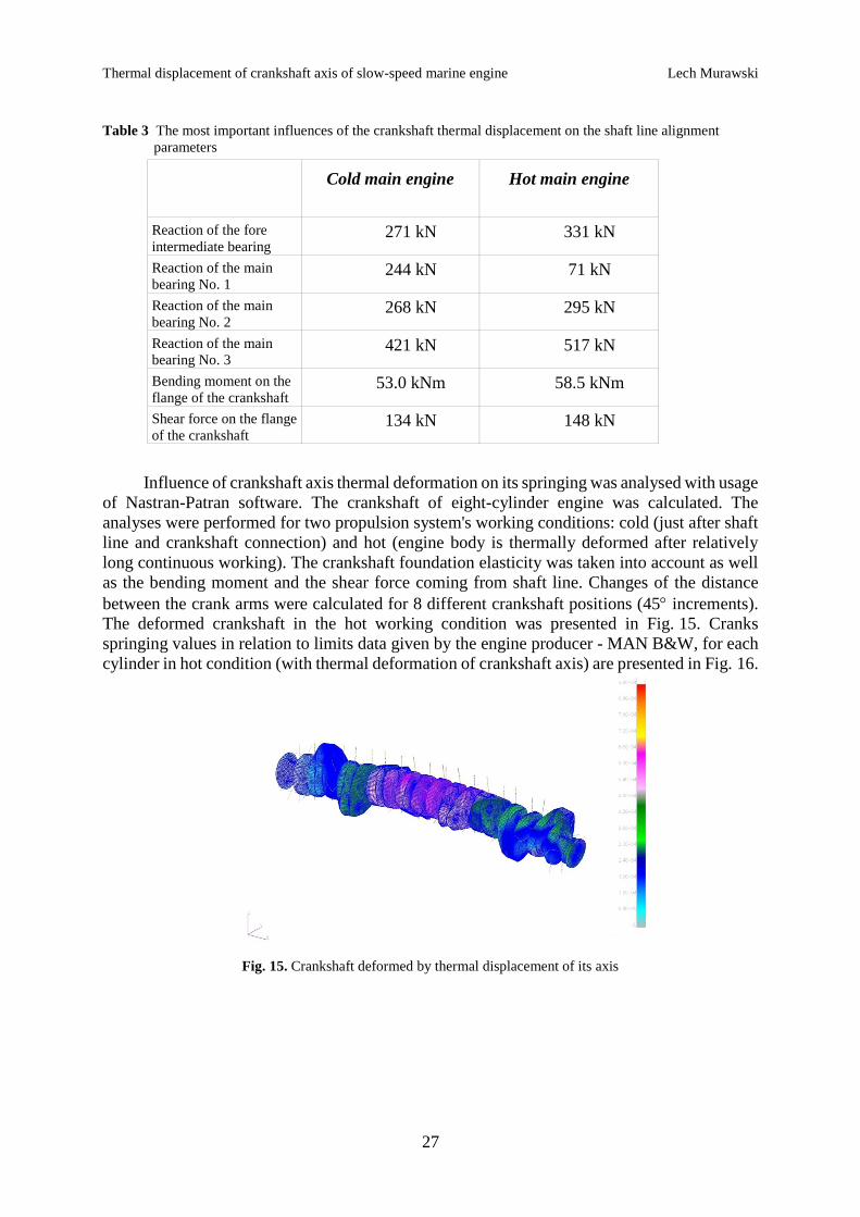
Influence of crankshaft axis thermal deformation on its springing was analysed with usage
of Nastran-Patran software. The crankshaft of eight-cylinder engine was calculated. The
analyses were performed for two propulsion system's working conditions: cold (just after shaft
line and crankshaft connection) and hot (engine body is thermally deformed after relatively
long continuous working). The crankshaft foundation elasticity was taken into account as well
as the bending moment and the shear force coming from shaft line. Changes of the distance
between the crank arms were calculated for 8 different crankshaft positions (45 increments).
The deformed crankshaft in the hot working condition was presented in Fig. 15. Cranks
springing values in relation to limits data given by the engine producer - MAN B&W, for each
cylinder in hot condition (with thermal deformation of crankshaft axis) are presented in Fig. 16.
Fig. 15. Crankshaft deformed by thermal displacement of its axis

Lech Murawski Thermal displacement of crankshaft axis of slow-speed marine engine
28
Fig. 16. Relative cranks' springing values in hot condition
The influence of the shaft line on the crankshaft loading (the bending moment and the
shear force), just after connection (cold condition) is inconsiderable. The springing difference
before and after connection do not exceed 1% for most cranks. Only for the second and third
crank it is greater but still does not exceed 3%. The thermal deformation of the crankshaft axis
has big influence on two first cranks: the change of those cranks springing in relation to the
limit values achieved 14%. Influence on the rest of cranks is much smaller the difference does
not exceed 2.5%. It means that the loading values of the first three main bearings may be higher
than theoretical.
6. Conclusions
The first significant natural modes (eigenvalues) of engine body have natural frequencies
above the range of excitation frequencies of the propulsion system. What's more the significant
natural modes are quite few and those of interest are of the whole engine's body. It speaks well
about the right design – the rigid structure of the engine's body. Therefore, dynamic stiffness of
the engine bearings should not be much different to the static stiffness. While the boundary
conditions (the modelling method of the ship hull and the engine foundation) have not very
important influence on natural frequencies of main bearings foundations, the global engine
eigenvalues are completely different. The modelling method of boundary conditions is essential
during engine body analyses.
The thermal displacement of the crankshaft computed by numerical analysis is greater
than the value recommended by the producer. The difference is not particularly big (bellow
20%) but the displacement is hogging type and is a source of the additonal bending moment
and shear force acting between the crankshaft and the shaft line. It seems that the producer’s
assumption about the parallel translation of the crankshaft’s axis is incorrect. The effect seems
to be considerable for the precise shaft line alignment analysis. Presented conclusion should be
treated with caution because the thermal deformation of ship hull is not taken into account.
Horizontal deformations of the crankshaft axis under the heating are negligible, in spite of the
temperature differences between left and right sides of the engine body.
The detailed thermal deformation of the crankshaft axis has not big influence on
calculation results of the global parameters of the shaft line alignment. But the hogging type of
the thermal deformation of the crankshaft axis has significant influence on the mutual loading
between the crankshaft and the shaft line. Loadings of the intermediate bearing close to the
crankshaft as well as loadings of three first engine's main bearings can change significantly.
The thermal deformation of crankshaft axis has also big influence on the crankshaft springing
0 45 90 135 180 225 270 315 3603600
2.5
5
7.5
10
12.5
1515
Crank rotation [deg]
Diffe
ren
ce
of
cra
nk s
pring
ing [
%]
C1
C2
C3
C4
C5
C6
C7
C8
Thermal displacement of crankshaft axis of slow-speed marine engine Lech Murawski
29
for two first cranks. It also means that the loading value of the first three main bearings may be
higher than theoretical.
This direction of research looks very promising. It may allow improvement in installation
of high power propulsion systems and avoiding failure of the engine's main bearings. The
worked out methodology may be used for more advanced and complete numerical computations
for multiple main engine types together with specific ship's hulls. As a further step, the
propulsion system analysis methodology should be elaborated, which incorporates more
complex crankshaft representation including in full its 3D characteristics. The effect of
crankshaft's springing on the shaft line alignment should also be examined further.
REFERENCES
[1] Guidance notes on propulsion shafting alignment. American Bureau of Shipping, Houston 2004.
[2] Shafting alignment for direct coupled low-speed diesel propulsion plants. MAN B&W Diesel A/S, Copenhagen
1995.
[3] Simm A., Qing Wang, Songling Huang, Wei Zhao: Laser based measurement for the monitoring of shaft
misalignment, Measurement, Vol. 87, pp. 104–116, 2016. http://dx.doi.org/10.1016/j.measurement.2016.02.034.
[4] Min Churl Songa, Young Hoon Moon: Coupled electromagnetic and thermal analysis of induction heating for the
forging of marine crankshafts, Applied Thermal Engineering, Vol. 98, pp. 98–109, 2016.
http://dx.doi.org/10.1016/j.applthermaleng.2015.11.129.
[5] Fontea M., Duartea P., Anesb V., Freitasb M., Reisb L.: On the assessment of fatigue life of marine diesel engine
crankshafts, Engineering Failure Analysis, Vol. 56, pp. 51–57, 2015.
http://dx.doi.org/10.1016/j.engfailanal.2015.04.014.
[6] Yong Yang, Wenyong Tang, Jie Ma: Analysis of shafting alignment for container vessels based on improved
transition matrix method, Procedia Engineering, Vol. 15, pp. 5373 – 5377, 2011.
http://dx.doi.org/10.1016/j.proeng.2011.08.996.
[7] Rules for classification of ships, Rotating Machinery, Power Transmission, Chapter 4, Part 4. Det Norske Veritas,
July 2013.
[8] Sulzer RTA-C. Technology Review. Wartsila, Helsinki 2003.
[9] Bearings. MAN B&W Diesel A/S, Copenhagen 2000.
[10] Elasto-hydro-dynamic evaluation of main bearing performance. MAN B&W Diesel A/S, Copenhagen 2002.
[11] Andersen IMV, Jensen J.J.: Measurements in a container ship of wave-induced hull girder stresses in excess of
design values. Marine Structures, Vol. 37, pp. 54-85, 2014. http://dx.doi.org/10.1016/j.marstruc.2014.02.006.
[12] Iijima K, Yao T, Moan T.: Structural response of a ship in severe seas considering global hydroelastic vibrations.
Marine Structures, Vol. 21, pp. 420-445, 2008. http://dx.doi.org/10.1016/j.marstruc.2008.03.003.
[13] Murawski L., Charchalis A.: Simplified method of torsional vibration calculation of marine power transmission
system. Marine Structures Vol. 39, pp 335-349, 2014. http://dx.doi.org/10.1016/j.marstruc.2014.10.004.
[14] Senjanović I., Vladimir N., Tomić M., Hadžić N., Malenica Š.: Some aspects of structural modelling and restoring
stiffness in hydroelastic analysis of large container ships, Ships and Offshore Structures, Vol. 9, No. 2, 2014., pp.
199-217. http://dx.doi.org/10.1080/17445302.2012.762728.
[15] Murawski L.: Shaft line alignment analysis taking ship construction flexibility and deformations into consideration.
Marine Structures, Vol. 18, pp. 62-84, 2005. http://dx.doi.org/10.1016/j.marstruc.2005.05.002.
[16] Murawski L.: Shaft line whirling vibrations: effects of numerical assumptions on analysis results. Marine
Technology and SNAME News, vol. 42, no. 2, pp. 5361, 2005.
[17] Murawski L.: Static and Dynamic Analyses of Marine Propulsion Systems. Oficyna Wydawnicza Politechniki
Warszawskiej, Warszawa 2003, pp. 148.
[18] Murawski L., Szmyt M.: Stifness characteristics and thermal deformations of the frame of high power marine
engine. Polish Maritime Research No 1(51), Vol. 14, pp. 1622, January 2007.
Submitted: 07.06.2016
Accepted: 28.07.2016
Lech Murawski, [email protected]
Gdynia Maritime University
ul. Morska 81-87, 81-225 Gdynia, Poland
tel.: +4858 6901 480, fax: +4858 690 13 99


![Propulsion engine N4 - tonissi.com · Propulsion engine N4.38 Speci˜cations Power at crankshaft 27.6 kW [37.5 hp] Displacement 1.498 l [91 in³] Con˜guration 4 cylinders in line](https://img.pdfslide.us/doc/110x75/5e108095ef7b973564677c2e/propulsion-engine-n4-propulsion-engine-n438-specioecations-power-at-crankshaft.jpg)


![Propulsion engine N9.600 CR2s3.amazonaws.com/hoth.bizango/assets/13983/Leaflet_N9.600_CR2.pdf · Propulsion engine N9.600 CR2 Speci˜cations Power at crankshaft 410 kW [557 hp] Displacement](https://img.pdfslide.us/doc/110x75/5e33242b497a5379d66a07b1/propulsion-engine-n9600-cr2s3-propulsion-engine-n9600-cr2-specioecations-power.jpg)