Embed Size (px)
Citation preview

NASA/TP-2004-212041
Thermal Buckling Analysis of Rectangular Panels Subjected to Humped Temperature Profile Heating
William L. KoNASA Dryden Flight Research CenterEdwards, California
January 2004

The NASA STI Program Office…in Profile
Since its founding, NASA has been dedicatedto the advancement of aeronautics and space science. The NASA Scientific and Technical Information (STI) Program Office plays a keypart in helping NASA maintain thisimportant role.
The NASA STI Program Office is operated byLangley Research Center, the lead center forNASA’s scientific and technical information.The NASA STI Program Office provides access to the NASA STI Database, the largest collectionof aeronautical and space science STI in theworld. The Program Office is also NASA’s institutional mechanism for disseminating theresults of its research and development activities. These results are published by NASA in theNASA STI Report Series, which includes the following report types:
• TECHNICAL PUBLICATION. Reports of completed research or a major significantphase of research that present the results of NASA programs and include extensive dataor theoretical analysis. Includes compilations of significant scientific and technical data and information deemed to be of continuing reference value. NASA’s counterpart of peer-reviewed formal professional papers but has less stringent limitations on manuscriptlength and extent of graphic presentations.
• TECHNICAL MEMORANDUM. Scientificand technical findings that are preliminary orof specialized interest, e.g., quick releasereports, working papers, and bibliographiesthat contain minimal annotation. Does notcontain extensive analysis.
• CONTRACTOR REPORT. Scientific and technical findings by NASA-sponsored contractors and grantees.
• CONFERENCE PUBLICATION. Collected papers from scientific andtechnical conferences, symposia, seminars,or other meetings sponsored or cosponsoredby NASA.
• SPECIAL PUBLICATION. Scientific,technical, or historical information fromNASA programs, projects, and mission,often concerned with subjects havingsubstantial public interest.
• TECHNICAL TRANSLATION. English- language translations of foreign scientific and technical material pertinent toNASA’s mission.
Specialized services that complement the STIProgram Office’s diverse offerings include creating custom thesauri, building customizeddatabases, organizing and publishing researchresults…even providing videos.
For more information about the NASA STIProgram Office, see the following:
• Access the NASA STI Program Home Pageat
http://www.sti.nasa.gov
• E-mail your question via the Internet to [email protected]
• Fax your question to the NASA Access HelpDesk at (301) 621-0134
• Telephone the NASA Access Help Desk at(301) 621-0390
• Write to:NASA Access Help DeskNASA Center for AeroSpace Information7121 Standard DriveHanover, MD 21076-1320

NASA/TP-2004-212041
Thermal Buckling Analysis of Rectangular Panels Subjected to Humped Temperature Profile Heating
William L. KoNASA Dryden Flight Research CenterEdwards, California
January 2004
National Aeronautics andSpace Administration
Dryden Flight Research CenterEdwards, California 93523-0273

NOTICE
Use of trade names or names of manufacturers in this document does not constitute an official endorsementof such products or manufacturers, either expressed or implied, by the National Aeronautics andSpace Administration.
Available from the following:
NASA Center for AeroSpace Information (CASI) National Technical Information Service (NTIS)7121 Standard Drive 5285 Port Royal RoadHanover, MD 21076-1320 Springfield, VA 22161-2171(301) 621-0390 (703) 487-4650

iii
CONTENTS
Page
ABSTRACT . . . . . . . . . . . . . . . . . . . . . . . . . . . . . . . . . . . . . . . . . . . . . . . . . . . . . . . . . . . . . . . . . . . . . . . . 1
NOMENCLATURE . . . . . . . . . . . . . . . . . . . . . . . . . . . . . . . . . . . . . . . . . . . . . . . . . . . . . . . . . . . . . . . . . . 1Acronyms . . . . . . . . . . . . . . . . . . . . . . . . . . . . . . . . . . . . . . . . . . . . . . . . . . . . . . . . . . . . . . . . . . . . . . . 1Symbols . . . . . . . . . . . . . . . . . . . . . . . . . . . . . . . . . . . . . . . . . . . . . . . . . . . . . . . . . . . . . . . . . . . . . . . . . 1
INTRODUCTION . . . . . . . . . . . . . . . . . . . . . . . . . . . . . . . . . . . . . . . . . . . . . . . . . . . . . . . . . . . . . . . . . . . . 3
HUMPED TEMPERATURE PROFILES . . . . . . . . . . . . . . . . . . . . . . . . . . . . . . . . . . . . . . . . . . . . . . . . . . 4Dome-Shaped Temperature Profile . . . . . . . . . . . . . . . . . . . . . . . . . . . . . . . . . . . . . . . . . . . . . . . . . . . . 4Roof-Shaped Temperature Profile . . . . . . . . . . . . . . . . . . . . . . . . . . . . . . . . . . . . . . . . . . . . . . . . . . . . 4
PROBLEMS INVESTIGATED . . . . . . . . . . . . . . . . . . . . . . . . . . . . . . . . . . . . . . . . . . . . . . . . . . . . . . . . . 5
FINITE-ELEMENT BUCKLING ANALYSIS . . . . . . . . . . . . . . . . . . . . . . . . . . . . . . . . . . . . . . . . . . . . . 5Panel Geometry . . . . . . . . . . . . . . . . . . . . . . . . . . . . . . . . . . . . . . . . . . . . . . . . . . . . . . . . . . . . . . . . . . . 5Material Properties . . . . . . . . . . . . . . . . . . . . . . . . . . . . . . . . . . . . . . . . . . . . . . . . . . . . . . . . . . . . . . . . 5Boundary Conditions . . . . . . . . . . . . . . . . . . . . . . . . . . . . . . . . . . . . . . . . . . . . . . . . . . . . . . . . . . . . . . 6Thermal Loads . . . . . . . . . . . . . . . . . . . . . . . . . . . . . . . . . . . . . . . . . . . . . . . . . . . . . . . . . . . . . . . . . . . 6
BUCKLING TEMPERATURE MAGNIFICATION FACTORS . . . . . . . . . . . . . . . . . . . . . . . . . . . . . . . 7
MINIMUM POTENTIAL ENERGY BUCKLING ANALYSIS . . . . . . . . . . . . . . . . . . . . . . . . . . . . . . . . 8Energy Equations . . . . . . . . . . . . . . . . . . . . . . . . . . . . . . . . . . . . . . . . . . . . . . . . . . . . . . . . . . . . . . . . . 8Deformation Functions . . . . . . . . . . . . . . . . . . . . . . . . . . . . . . . . . . . . . . . . . . . . . . . . . . . . . . . . . . . . . 9Buckling Equations . . . . . . . . . . . . . . . . . . . . . . . . . . . . . . . . . . . . . . . . . . . . . . . . . . . . . . . . . . . . . . . . 9Buckling Temperatures for Isotropic Cases . . . . . . . . . . . . . . . . . . . . . . . . . . . . . . . . . . . . . . . . . . . . 11
RESULTS . . . . . . . . . . . . . . . . . . . . . . . . . . . . . . . . . . . . . . . . . . . . . . . . . . . . . . . . . . . . . . . . . . . . . . . . . 13Buckling Temperature Magnification Factors . . . . . . . . . . . . . . . . . . . . . . . . . . . . . . . . . . . . . . . . . . 13In-Plane Deformations . . . . . . . . . . . . . . . . . . . . . . . . . . . . . . . . . . . . . . . . . . . . . . . . . . . . . . . . . . . . 18Thermal Stresses . . . . . . . . . . . . . . . . . . . . . . . . . . . . . . . . . . . . . . . . . . . . . . . . . . . . . . . . . . . . . . . . . 18
CONCLUDING REMARKS . . . . . . . . . . . . . . . . . . . . . . . . . . . . . . . . . . . . . . . . . . . . . . . . . . . . . . . . . . . 19
APPENDIX A—TEMPERATURE-DEPENDENT MATERIAL PROPERTIES OF HAYNES 230 ALLOY . . . . . . . . . . . . . . . . . . . . . . . . . . . . . . . . . . . . . . . . . . . . . . . . . . . . . . . . . . . . . . . . . . . . . . . . . . . 21
APPENDIX B—COEFFICIENTS OF CHARACTERISTIC EQUATIONS . . . . . . . . . . . . . . . . . . . . . . 22
APPENDIX C—TABLE OF SPECIAL INTEGRALS . . . . . . . . . . . . . . . . . . . . . . . . . . . . . . . . . . . . . . 27
APPENDIX D—BUCKLING EQUATIONS . . . . . . . . . . . . . . . . . . . . . . . . . . . . . . . . . . . . . . . . . . . . . . 29
REFERENCES . . . . . . . . . . . . . . . . . . . . . . . . . . . . . . . . . . . . . . . . . . . . . . . . . . . . . . . . . . . . . . . . . . . . . 33
FIGURES . . . . . . . . . . . . . . . . . . . . . . . . . . . . . . . . . . . . . . . . . . . . . . . . . . . . . . . . . . . . . . . . . . . . . . . . . . 34

iv
ABSTRACT
This research investigates thermal buckling characteristics of rectangular panels subjected to different types ofhumped temperature profile heating. Minimum potential energy and finite-element methods are used to calculatethe panel buckling temperatures. The two methods give fairly close thermal buckling solutions. “Bucklingtemperature magnification factor of the first kind,
η
” is established for the fixed panel edges to scale up thebuckling solution of uniform temperature loading case to give the buckling solution of the humped temperatureprofile loading cases. Also, “buckling temperature magnification factor of the second kind,
ξ
” is established for thefree panel edges to scale up the buckling solution of humped temperature profile loading cases with unheatedboundary heat sinks to give the buckling solutions when the boundary heat sinks are heated up.
NOMENCLATURE
Acronyms
BC boundary condition
JLOC joint location
SPAR Structural Performance and Resizing
TPS thermal protection system
Symbols
A
kl
Fourier coefficient of trial function for out-of-plane displacement
w
, in.
A
ij
extensional stiffness of orthotropic plates, , ,
, , , lb/in.
AR
=
a/b
, plate aspect ratio
a
length of plate, in.
coefficient of characteristic equation
B
mn
Fourier coefficient of trial function for , in/in.
b
width of plate, in.
C
mn
Fourier coefficient of trial function for , in/in.
D
ij
bending stiffness of plate, , , ,
, , in-lb
D
Qx
, D
Qy
transverse shear stiffness in
xz-
,
yz-
planes, lb/in.
A11tsEx
1 νxyνyx–-------------------------= A12
tsνyxEx
1 νxyνyx–-------------------------=
A21tsνxyEy
1 νxyνyx–-------------------------= A22
tsEy
1 νxyνyx–-------------------------= A66 2tsGxy=
amnklij
γ xz
γ yz
D11
ExIs
1 νxyνyx–-------------------------= D12
νyxExIs
1 νxyνyx–-------------------------= D21
νxyEyIs
1 νxyνyx–-------------------------=
D22
EyIs
1 νxyνyx–-------------------------= D66 2GxyIs=
2
E
Young’s modulus, lb/in
2
E
x
,
E
y
Young’s modulus, lb/in
2
G
xy
shear modulus, lb/in
2
I
s
moment of inertia, per unit width, with respect to plate centroidal axis, , in
4
/in.
i
index, 1, 2, 3,....
j
index, 1, 2, 3,....
k
index, 1, 2, 3,....
l
index, 1, 2, 3,....
m
index, 1, 2, 3,...., number of buckle half waves in
x
-direction
, , thermal forces, lb/in.
n
index,1, 2, 3,...., number of buckle half waves in
y
-direction
T
temperature (measured from room temperature), ˚F
T
c
temperature for constant temperature profile heating, ˚F
T
m
material temperature
T
o
peak temperature of dome-shaped (or roof-shaped) temperature profile heating, ˚F
T
s
boundary heat sink temperature, ˚F
t
s
thickness of plate, in.
u x
-displacement, in.
v y
-displacement, in.
w out-of-plane displacement, in.
x, y, z rectangular Cartesian coordinates
α, αx, αy coefficient of thermal expansion, in/in-˚F
αxy coefficient of thermal shear distortion, in/in-˚F
, transverse shear strain in xz- and yz-planes, in/in.
ζ numerical factor in buckling equation written for specified panel edge condition
η , “buckling temperature magnification factor of the first kind” = buckling
temperature of dome temperature loading case (fixed or free support condition)
divided by the buckling temperature of uniform temperature loading case (fixed
boundaries)
thermal buckling eigenvalue associated with constant temperature profile heating
thermal buckling eigenvalue associated with dome-shaped (or roof-shaped) profile heating
Poisson ratio
Is112------ts
3=
N xT
N yT
N xyT
γ xz γ yz
T o( )cr
T c( )cr
⁄=
T o( )cr
T c( )cr
λc
λo
ν
3
ξ “buckling temperature magnification factor of the second
kind” = buckling temperature of dome temperature loading case with any heat sink
temperature (free support condition) divided by the buckling temperature of
dome temperature loading case with zero heat sink temperature (free support
condition)
ρ density, lb/in3
σT tensile strength, lb/in2
σx stress in x-direction, lb/in2
σY yield stress, lb/in2
σy stress in y-direction, lb/in2
τ shear stress, lb/in2
( )cr critical value at buckling
INTRODUCTION
Hypersonic aircraft are subjected to severe aerodynamic heating during flights. To maintain the structuralintegrity under high temperature environment, the vehicle structural design concepts of hypersonic flight vehiclesare different from those of low Mach number aircraft. Depending on the operating temperature range, vehiclestructures may be called “hot” structures or “warm” structures. The “hot” structures fabricated with hightemperature alloys can operate at elevated temperatures in the range of 1000 °F to 1500 °F. If fabricated with thecarbon/carbon composite material, the operating temperature of the “hot” structures could go as high as 3000 °F.Typical candidate “hot” structural components for hypersonic flight vehicles are hat-stiffened panels fabricatedwith either monolithic titanium alloys or metal-matrix composite materials; honeycomb sandwich panelsfabricated with super-alloy; and carbon/carbon composite elevon (or body flap).
The “warm” structures are fabricated with lightweight materials, such as aluminum, and can operate only up tomoderate temperature limit of 350 °F. The space shuttle orbiter is a good example of the “warm” structure. Theentire vehicle is protected with the thermal protection system (TPS) to shield the aluminum substructure fromoverheating beyond the “warm” temperature limit.
Hot structural panels are usually fastened to the cooler substructures that function as heat sinks because of lessheating. Thus, even under the uniform surface heat flux, the temperature distribution over the hot structural panelswill not be uniform but looks like camel-humped shape (refs. 1–3). This camel-humped shaped temperaturedistribution is always observed in supported hot structural panels. The buckling behavior of the panel with heatsinks is therefore quite different from the case without heat sinks. Earlier Ko extensively studied thermal bucklingproblems of hot structural panels under uniform temperature profile heating (without heat sinks effects)(refs. 4–10).
This report studies the thermal buckling behavior of rectangular panels under different types ofhumped-shaped temperature profile heating to simulate the existence of the supporting boundary heat sink and alsostudies the effect of the heat sink temperature on the panel buckling temperature. The results are compared to theresults of uniform temperature profile heating cases without the heat sink effect.
T o( )cr
[ ]Ts 0≠
T o( )cr
[ ]Ts 0=
⁄=
T o( )cr
T s 0≠ T o( )cr
T s 0=
4
HUMPED TEMPERATURE PROFILES
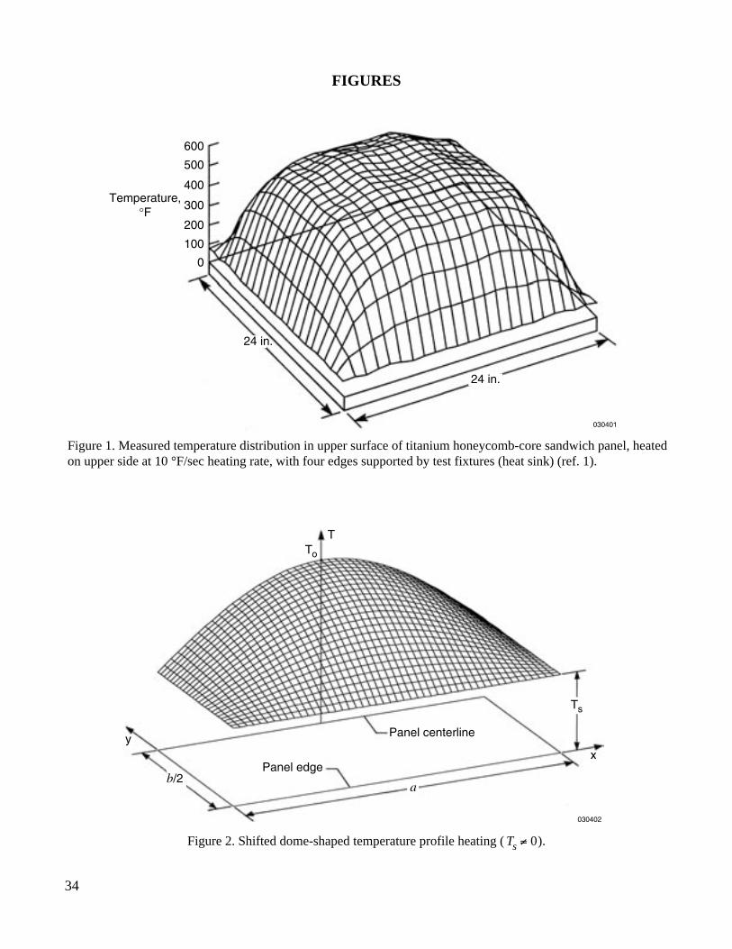
Under uniform surface heating, because of the existence of the supporting cooler boundary heat sinks,experimental data have shown that the temperature distribution over a hot structural panel is usuallyflattened-dome shaped (fig. 1, ref. 1). For performing thermostructural analysis, the actual temperature profile maybe idealized with simple mathematical surfaces such as dome-shaped or roof-shaped temperature profilesdescribed in the following sections.
Dome-Shaped Temperature Profile
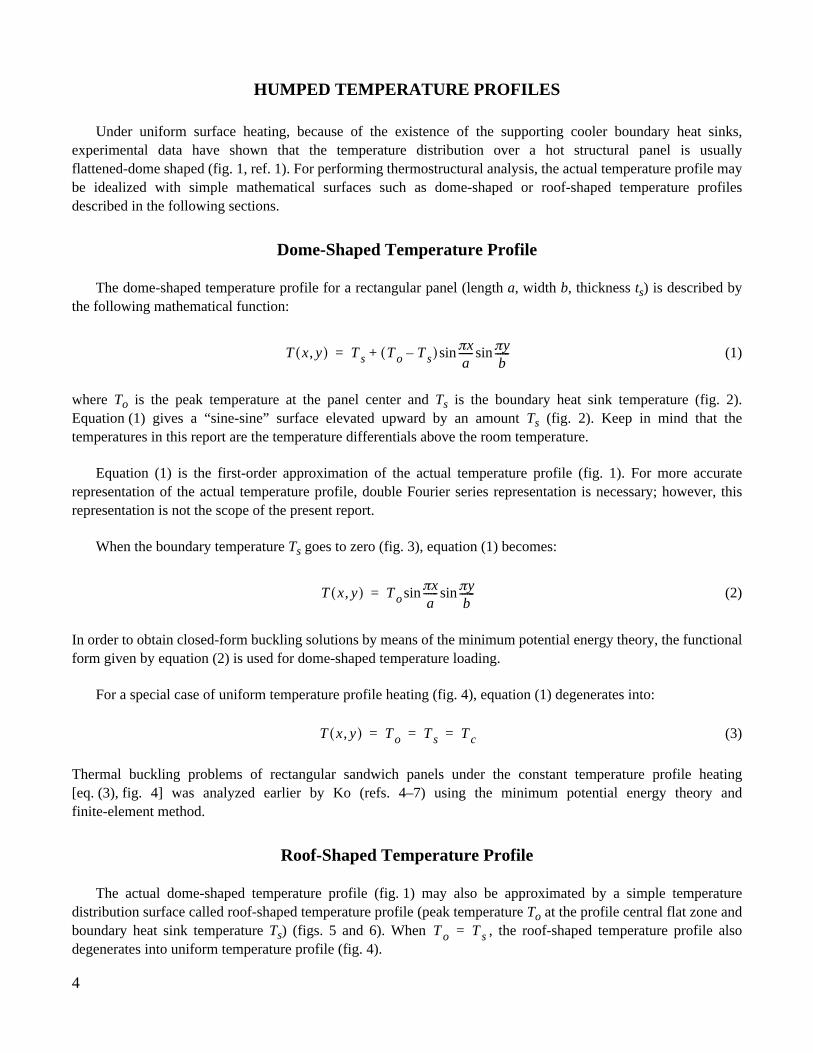
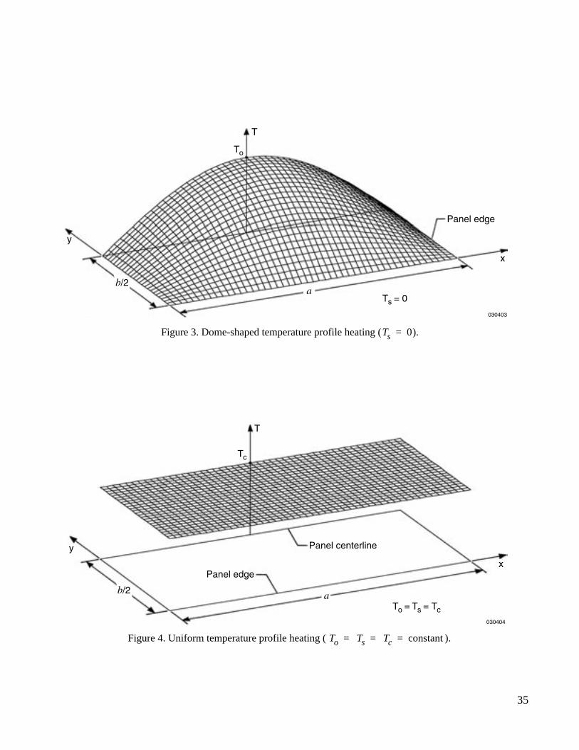
The dome-shaped temperature profile for a rectangular panel (length a, width b, thickness ts) is described bythe following mathematical function:
(1)
where To is the peak temperature at the panel center and Ts is the boundary heat sink temperature (fig. 2).Equation (1) gives a “sine-sine” surface elevated upward by an amount Ts (fig. 2). Keep in mind that thetemperatures in this report are the temperature differentials above the room temperature.
Equation (1) is the first-order approximation of the actual temperature profile (fig. 1). For more accuraterepresentation of the actual temperature profile, double Fourier series representation is necessary; however, thisrepresentation is not the scope of the present report.
When the boundary temperature Ts goes to zero (fig. 3), equation (1) becomes:
(2)
In order to obtain closed-form buckling solutions by means of the minimum potential energy theory, the functionalform given by equation (2) is used for dome-shaped temperature loading.
For a special case of uniform temperature profile heating (fig. 4), equation (1) degenerates into:
(3)
Thermal buckling problems of rectangular sandwich panels under the constant temperature profile heating[eq. (3), fig. 4] was analyzed earlier by Ko (refs. 4–7) using the minimum potential energy theory andfinite-element method.
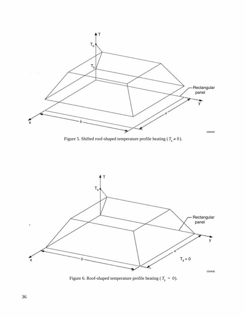
Roof-Shaped Temperature Profile
The actual dome-shaped temperature profile (fig. 1) may also be approximated by a simple temperaturedistribution surface called roof-shaped temperature profile (peak temperature To at the profile central flat zone andboundary heat sink temperature Ts) (figs. 5 and 6). When , the roof-shaped temperature profile alsodegenerates into uniform temperature profile (fig. 4).
T x y,( ) T s T o T s–( ) πxa
------ πyb
------sinsin+=
T x y,( ) T oπxa
------ πyb
------sinsin=
T x y,( ) T o T s T c= = =
T o T s=

5
PROBLEMS INVESTIGATED
This report investigated thermal buckling behavior of rectangular panels (length a, width b, thickness ts)heated under the dome-shaped (figs. 2 and 3) and roof-shaped (figs. 5 and 6) temperature profiles. The mainaspects of this research are:
1. To study the effect of the dome-shaped (or roof-shaped) temperature profile on the buckling behavior of therectangular panels with fixed edges. Then, the study will establish the “buckling temperature magnificationfactor of the first kind” to scale up the buckling solution of uniform temperature profile heating case to givethe buckling solution of the dome-/roof-shaped temperature profile heating case.
2. To study the effect of the heat sink temperatures on the buckling temperatures of rectangular panels withfree edges under dome-shaped (or roof-shaped) temperature profile heating. Then, the study will establishthe “buckling temperature magnification factor of the second kind” to scale up the buckling solution ofdome (or roof) temperature loading case with unheated boundary heat sinks to give the buckling solutionswhen the boundary heat sinks are heated up.
FINITE-ELEMENT BUCKLING ANALYSIS
This research will use the Structural Performance and Resizing (SPAR) finite-element computer program (ref.11) to conduct the linear elastic thermal buckling analysis of the rectangular panels.
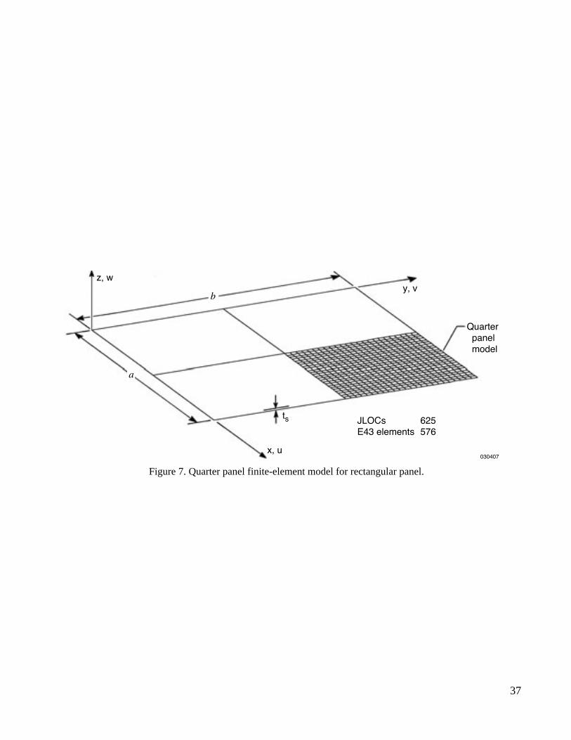
Panel Geometry
All the rectangular panels analyzed have thickness ts = 0.09 in. with the different dimensions in length a andwidth b listed in Table 1.
Figure 7 shows the quarter model generated for the rectangular panel. The quarter model has 625 jointlocations (JLOCs) and 576 E43 four-node plate elements.
Material Properties
The rectangular panels are made of high temperature alloy Haynes® 230® (Haynes International, Koyomo,Indiana) with the room temperature properties listed in Table 2.
Table 1. Dimensions of rectangular panels; ts = 0.09 in.
a, in. b, in. a/b
6 6 1.09 6 1.5
12 6 2.0

6
Haynes 230 high temperature alloy was used in the fabrication of Hyper-X (X-43) hypersonic research vehiclefor Mach 7–10 mission (ref. 3). Appendix A gives the temperature-dependent material properties of Haynes 230alloy.
Boundary Conditions
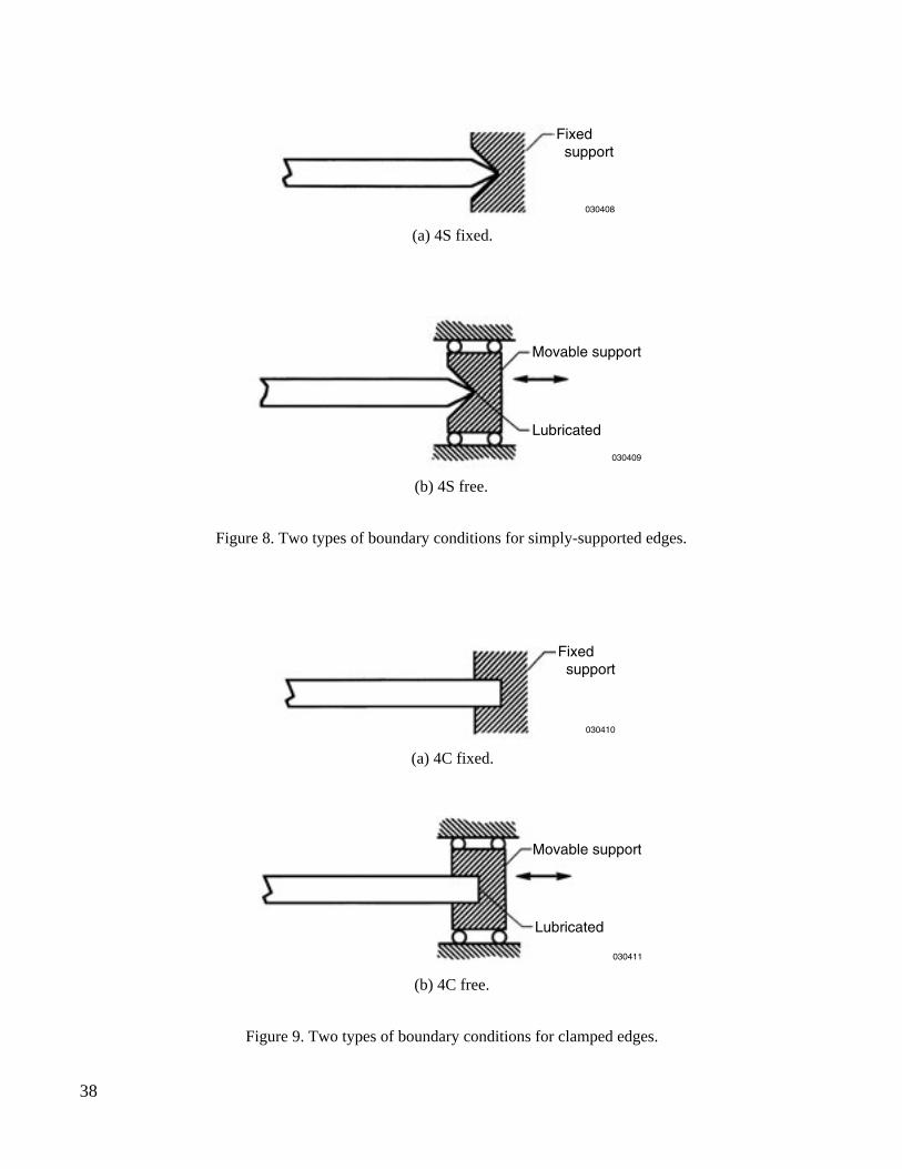
The following different panel boundary conditions were considered in the finite-element analysis:
1. 4S fixed — four edges simply supported, with no in-plane displacements [fig. 8(a)].
a. , everywhere except boundaries.
b. , everywhere in the panel.
2. 4S free — four edges simply supported and slides freely along the lubricated guides, which can have freein-plane motions [fig. 8(b)].
3. 4C fixed — four edges clamped, with no in-plane displacements [fig. 9(a)].
a. , everywhere except boundaries.
b. , everywhere in the panel.
4. 4C free — four edges clamped and slides freely along the lubricated clamping guides, which can have freein-plane motions [fig. 9(b)].
Thermal Loads
The thermal load inputs used for the dome (or roof) temperature loading and constant temperature loading areas follows.
1. Dome-Shaped (or Roof-Shaped) Temperature Profile Heating
For the dome-shaped [eqs. (1) and (2), figs. 2 and 3] and roof-shaped (figs. 5 and 6) temperature load inputs tothe SPAR program for the eigenvalue calculations, the unit peak temperature °F was used. The heat sinktemperature Ts was allowed to vary over the range (i.e., = 0, 0.1, 0.2, 0.3, 0.4, 0.5, 0.6, 0.7,0.8, 0.9, 1.0). Then the eigenvalue (scaling factor) calculated from SPAR program will give the bucklingtemperature , namely:
(4)
Table 2. Material properties of Haynes 230 alloy at room temperature.
E lb/in2
0.31
ρ 0.324 lb/in3
α in/in-°F
30.6 106
×
ν
7.0 106–
×
u x y,( ) 0≠ v x y,( ) 0≠
u x y,( ) 0= v x y,( ) 0=
u x y,( ) 0≠ v x y,( ) 0≠
u x y,( ) 0= v x y,( ) 0=
T o 1=T s T o⁄ 0~1= T s T o⁄λo
T o( )cr
T o( )cr
λo 1 λo=×=
7
If the input peak temperature To is doubled (i.e., °F), then the calculated eigenvalue will be reduced to halfof given in equation (4) because the product remains constant.
The reason for using the whole range of is to study the effect of the heat sink temperature Ts onthe panel buckling temperature when the panel edges are free to move. Keep in mind that the panelbuckling temperature will increase with the increasing heat sink temperature Ts because of relaxation ofthermal expansion constraint exerted on the panel by the boundary heat sink.
2. Uniform Temperature Profile Heating
As mentioned earlier, the uniform-temperature loading case (fig. 4) is a degenerative case of dome-shaped (orroof-shaped) temperature profile heating. Temperature load of ºF is chosen as input to all nodes of thefinite-element model so that the eigenvalue calculated from SPAR program will give the buckling temperature
, namely:
(5)
This buckling solution is for the panels with fixed boundary supports. When the panel boundaries can have freein-plane motions (free supports), the constant temperature loading case obviously can never induce thermalbuckling (i.e., buckling temperature goes to infinity).
3. Material Property Iterations
In the calculations of buckling temperatures, material property iterations are required to obtain accuratebuckling temperatures. Namely, the material properties at certain assumed material temperature Tm must beupdated until Tm matches the calculated buckling temperature . Reference 12 discusses in detail thisiteration process. Usually it takes only two to three material iterations to yield accurate buckling temperatures.
BUCKLING TEMPERATURE MAGNIFICATION FACTORS
As discussed later in this report, for the fixed supports (4S or 4C) [figs. 8(a) or 9(a)], the buckling temperature for the dome (or roof) temperature loading case is much higher than the buckling temperature of
the uniform temperature loading case. Therefore, a “buckling temperature magnification factor of the first kind, η”defined as:
(6)
will be used to indicate how many times the buckling temperature of the dome (or roof) temperatureloading case (fixed supports) is magnified from the buckling temperature of the uniform temperatureloading case with fixed supports (fundamental case).
In reality, the hot panel attempts to expand under heating; but its expansion is resisted by the cooler boundarysubstructures (heat sinks) that expand less. This boundary constraint is the cause of thermal buckling of the panels.Such substructure constraints will gradually relax as the substructures are heated up, resulting in higher panelbuckling temperature. In order to discover how the heat sink temperature Ts affects the panel buckling temperature
T o 2=λo T o λo×( )
T s T o⁄ 0~1=T o( )
crT o( )
cr
T c 1=λc
T c( )cr
T c( )cr
λc 1 λc=×=
T c( )cr
T o( )cr
T c( )cr
ηT o( )
cr
T c( )cr
----------------=
T o( )cr
T c( )cr

8
for the dome (or roof) temperature loading case with free supports, another “buckling temperaturemagnification factor of the second kind, ξ” defined as:
(7)
will be used to indicate how many times the buckling temperature for the dome (or roof) temperatureloading case with free support (4S or 4C) is magnified when the heat sink temperature Ts increases from (no heat sink thermal expansion) to certain nonzero value (with heat sink thermal expansion).
MINIMUM POTENTIAL ENERGY BUCKLING ANALYSIS
When the {u, v} displacements are zero everywhere in the plate including the boundaries (4S fixed-b and 4Cfixed-b cases), the dome-shaped temperature profile heating [eq. (2), fig. 3] will generate identical dome-shapedbiaxial stress distributions with no shear stresses. Because of this ideal condition, it is possible to obtainclosed-form buckling solutions for this particular case using the minimum potential energy theory.
Energy Equations
Strain energy associated with bending V1 may be written as (refs. 5 and 6):
(8)
and the strain energy associated with thermal loading V2 is given by:
(9)
The dome-shaped temperature loading functions may be expressed as follows (refs. 5 and 6):
(10)
(11)
(12)
The preceding thermal loading functions (10)–(12) hold only for the 4S fixed-b and 4C fixed-b cases[i.e., u(x,y) = 0, v(x,y) = 0 everywhere].
T o( )cr
ξ
T o( )cr Ts 0≠
T o( )cr Ts 0=
-----------------------------------=
T o( )cr
T s 0=T s 0≠
V 1
D11
2--------- ∂
∂x------ ∂w
∂x------- γ xz– 2
D12∂∂x------ ∂w
∂x------- γ xz– ∂
∂y----- ∂w
∂y------- γ yz–
D22
2--------- ∂
∂y----- ∂w
∂y------- γ yz– 2 D66
2--------- ∂
∂y----- ∂w
∂x------- γ xz– ∂
∂x------ ∂w
∂y------- γ yz– +
2 DQx
2----------γ xz
2 DQy
2----------γ yz
2+ + ++
+
xd yd
0
b
∫0
a
∫=
V 212---– N x
T ∂w∂x------- 2
2N xyT ∂w
∂x------- ∂w
∂y------- N y
T ∂w∂y------- 2
+ +0
b
∫0
a
∫ dxdy=
N xT
x y,( ) A11αx A12αy+( )T oπxa
------sin πyb
------sin=
N yT
x y,( ) A21αx A22αy+( )T oπxa
------sin πyb
------sin=
N xyT
x y,( ) 0=
9
For other fixed panel cases under dome temperature heating, the in-plane displacements of panel interior pointsare nonzero [i.e., u(x,y) ≠ 0, v(x,y) ≠ 0], and the thermal loads { , , } are complicated functions of {x,y};and thus it will be too cumbersome to apply the minimum potential energy method. Therefore, SPAR was used toobtain quick buckling solutions.
Deformation Functions
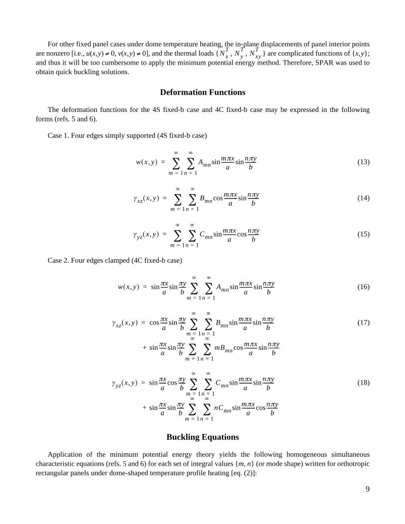
The deformation functions for the 4S fixed-b case and 4C fixed-b case may be expressed in the followingforms (refs. 5 and 6).
Case 1. Four edges simply supported (4S fixed-b case)
(13)
(14)
(15)
Case 2. Four edges clamped (4C fixed-b case)
(16)
(17)
(18)
Buckling Equations
Application of the minimum potential energy theory yields the following homogeneous simultaneouscharacteristic equations (refs. 5 and 6) for each set of integral values {m, n} (or mode shape) written for orthotropicrectangular panels under dome-shaped temperature profile heating [eq. (2)]:
N xT
N yT
N xyT
w x y,( ) Amnn 1=
∞
∑m 1=
∞
∑ mπxa
-----------sin nπyb
---------sin=
γ xz x y,( ) Bmnn 1=
∞
∑m 1=
∞
∑ mπxa
-----------cos nπyb
---------sin=
γ yz x y,( ) Cmnn 1=
∞
∑m 1=
∞
∑ mπxa
-----------sin nπyb
---------cos=
w x y,( ) πxa
------sin πyb
------sin Amnn 1=
∞
∑m 1=
∞
∑ mπxa
-----------sin nπyb
---------sin=
γ xz x y,( ) πxa
------cos πyb
------sin Bmnn 1=
∞
∑m 1=
∞
∑ mπxa
-----------sin nπyb
---------
+ πxa
------sin πyb
------sin mBmnn 1=
∞
∑m 1=
∞
∑ mπxa
-----------cos nπyb
---------sin
sin=
γ yz x y,( ) πxa
------sin πyb
------cos Cmnn 1=
∞
∑m 1=
∞
∑ mπxa
-----------sin nπyb
---------
+ πxa
------sin πyb
------sin nCmnn 1=
∞
∑m 1=
∞
∑ mπxa
-----------sin nπyb
---------cos
sin=
10
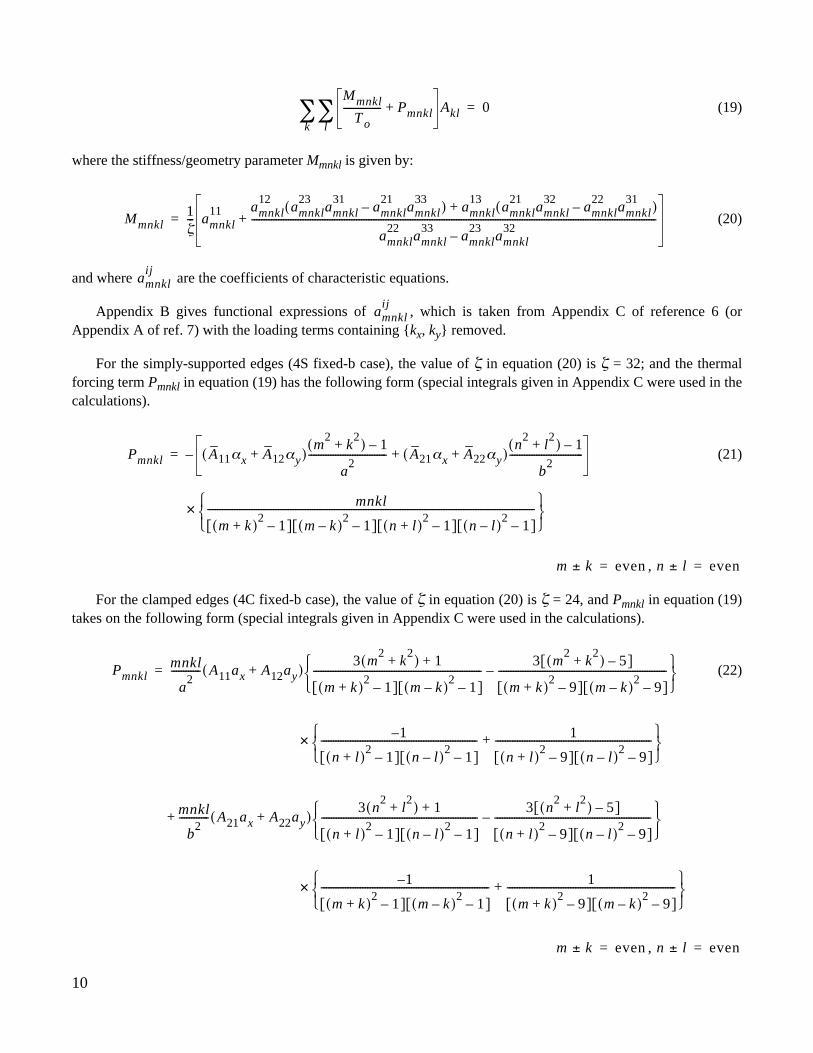
(19)
where the stiffness/geometry parameter Mmnkl is given by:
(20)
and where are the coefficients of characteristic equations.
Appendix B gives functional expressions of , which is taken from Appendix C of reference 6 (orAppendix A of ref. 7) with the loading terms containing {kx, ky} removed.
For the simply-supported edges (4S fixed-b case), the value of ζ in equation (20) is ζ = 32; and the thermalforcing term Pmnkl in equation (19) has the following form (special integrals given in Appendix C were used in thecalculations).
(21)
,
For the clamped edges (4C fixed-b case), the value of ζ in equation (20) is ζ = 24, and Pmnkl in equation (19)takes on the following form (special integrals given in Appendix C were used in the calculations).
(22)
,
Mmnkl
T o---------------- Pmnkl+ Akl
l∑
k∑ 0=
Mmnkl1ζ--- amnkl
11 amnkl12
amnkl23
amnkl31
amnkl21
amnkl33
–( ) amnkl13
amnkl21
amnkl32
amnkl22
amnkl31
–( )+
amnkl22
amnkl33
amnkl23
amnkl32
–----------------------------------------------------------------------------------------------------------------------------------------------------------------------+=
amnklij
amnklij
Pmnkl A11αx A12αy+( )m
2k
2+( ) 1–
a2
-------------------------------- A21αx A22αy+( )n
2l2
+( ) 1–
b2
------------------------------+
× mnkl
m k+( )2
1–[ ] m k–( )2
1–[ ] n l+( )2
1–[ ] n l–( )2
1–[ ]--------------------------------------------------------------------------------------------------------------------------------------
–=
m k± even= n l± even=
Pmnklmnkl
a2
------------ A11ax A12ay+( )3 m
2k
2+( ) 1+
m k+( )2
1–[ ] m k–( )2
1–[ ]---------------------------------------------------------------------
3 m2
k2
+( ) 5–[ ]
m k+( )2
9–[ ] m k–( )2
9–[ ]---------------------------------------------------------------------–
=
× 1–
n l+( )2
1–[ ] n l–( )2
1–[ ]---------------------------------------------------------------- 1
n l+( )2
9–[ ] n l–( )2
9–[ ]----------------------------------------------------------------+
+ mnkl
b2
------------ A21ax A22ay+( )3 n
2l2
+( ) 1+
n l+( )2
1–[ ] n l–( )2
1–[ ]----------------------------------------------------------------
3 n2
l2
+( ) 5–[ ]
n l+( )2
9–[ ] n l–( )2
9–[ ]----------------------------------------------------------------–
× 1–
m k+( )2
1–[ ] m k–( )2
1–[ ]--------------------------------------------------------------------- 1
m k+( )2
9–[ ] m k–( )2
9–[ ]---------------------------------------------------------------------+
m k± even= n l± even=
11
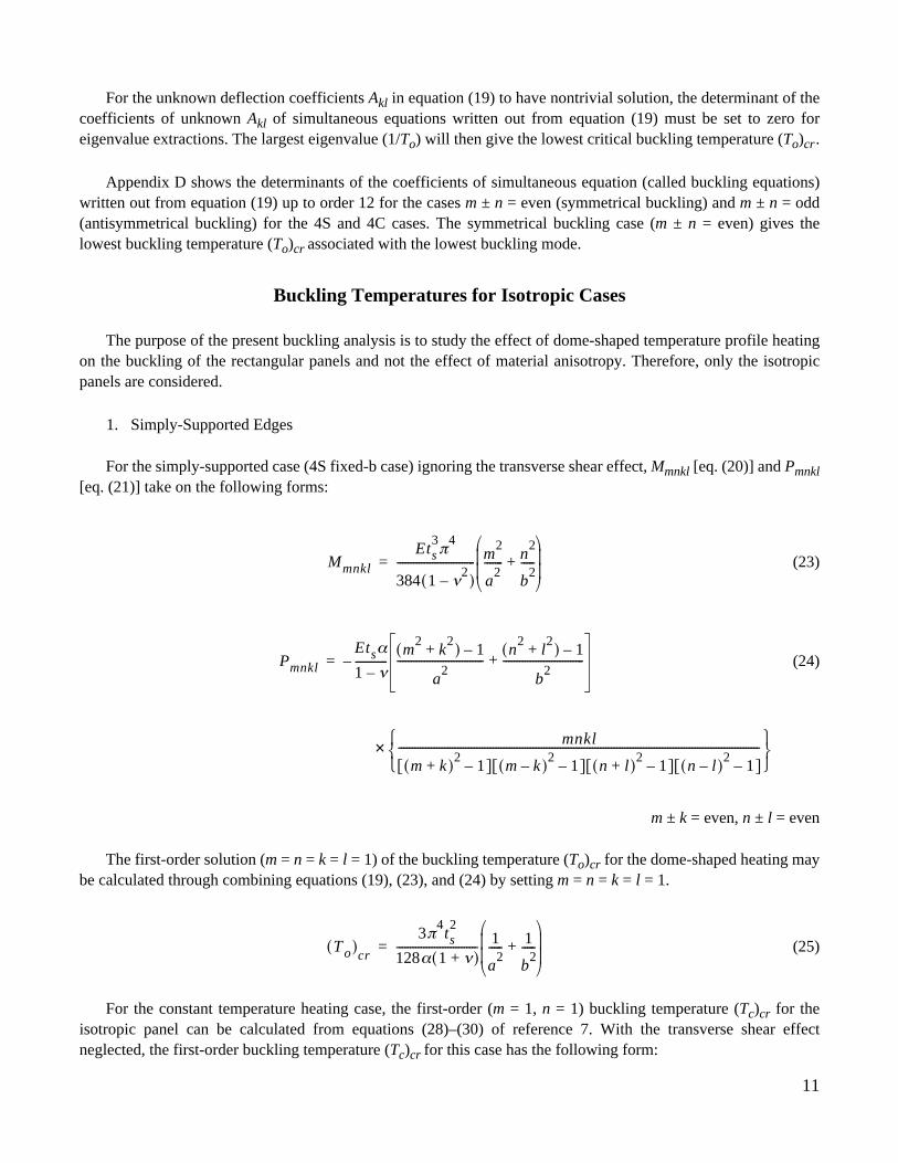
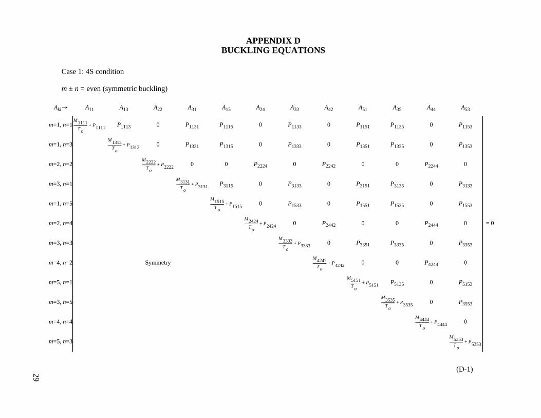
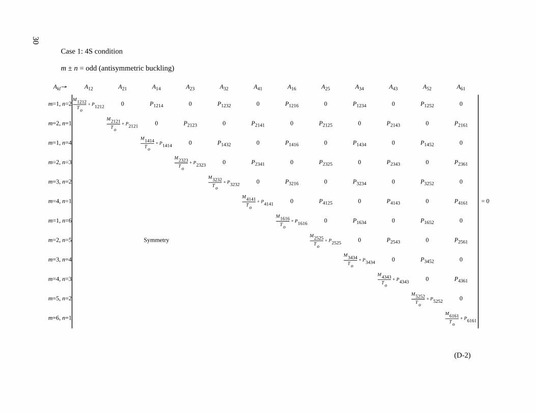
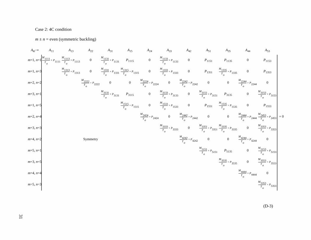
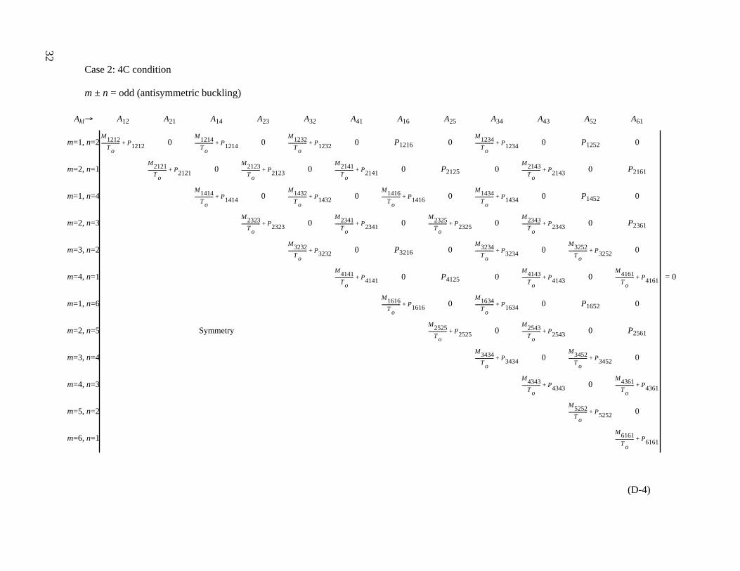
For the unknown deflection coefficients Akl in equation (19) to have nontrivial solution, the determinant of thecoefficients of unknown Akl of simultaneous equations written out from equation (19) must be set to zero foreigenvalue extractions. The largest eigenvalue (1/To) will then give the lowest critical buckling temperature (To)cr.
Appendix D shows the determinants of the coefficients of simultaneous equation (called buckling equations)written out from equation (19) up to order 12 for the cases m ± n = even (symmetrical buckling) and m ± n = odd(antisymmetrical buckling) for the 4S and 4C cases. The symmetrical buckling case (m ± n = even) gives thelowest buckling temperature (To)cr associated with the lowest buckling mode.
Buckling Temperatures for Isotropic Cases
The purpose of the present buckling analysis is to study the effect of dome-shaped temperature profile heatingon the buckling of the rectangular panels and not the effect of material anisotropy. Therefore, only the isotropicpanels are considered.
1. Simply-Supported Edges
For the simply-supported case (4S fixed-b case) ignoring the transverse shear effect, Mmnkl [eq. (20)] and Pmnkl[eq. (21)] take on the following forms:
(23)
(24)
m ± k = even, n ± l = even
The first-order solution (m = n = k = l = 1) of the buckling temperature (To)cr for the dome-shaped heating maybe calculated through combining equations (19), (23), and (24) by setting m = n = k = l = 1.
(25)
For the constant temperature heating case, the first-order (m = 1, n = 1) buckling temperature (Tc)cr for theisotropic panel can be calculated from equations (28)–(30) of reference 7. With the transverse shear effectneglected, the first-order buckling temperature (Tc)cr for this case has the following form:
Mmnkl
Ets3π
4
384 1 ν2
–( )----------------------------- m
2
a2
------- n2
b2
-----+
=
Pmnkl
Etsα
1 ν–------------–
m2
k2
+( ) 1–
a2
--------------------------------n
2l2
+( ) 1–
b2
------------------------------+=
× mnkl
m k+( )2
1–[ ] m k–( )2
1–[ ] n l+( )2
1–[ ] n l–( )2
1–[ ]--------------------------------------------------------------------------------------------------------------------------------------
T o( )cr
3π4ts2
128α 1 ν+( )------------------------------ 1
a2
----- 1
b2
-----+
=

12
(26)
Dividing equation (25) by equation (26) yields the buckling temperature magnification factor of the first kindη for the simply-supported first-order case (m = n = k = l = 1) in a neat form:
(27)
that is independent of panel aspect ratio.
For the 4S case, the values of η based on the second and third-order buckling solutions (which depend on theaspect ratio a/b) were also obtained. The RESULTS section presents these values.
2. Clamped Edges
For the clamped case (4C fixed-b case), the first-order solution (m = n = k = l = 1) for the “dome-shaped”temperature case is:
(28)
(29)
The first-order solution (m = n = k = l = 1) of the buckling temperature (To)cr for the clamped panel under thedome-shaped heating may be calculated by combining equations (19), (28), and (29) to yield:
(30)
The first-order solution (m = n = k = l = 1) for the constant temperature case calculated from equations(28)–(30) of reference 7 gives:
(31)
T c( )cr
π2ts2
12α 1 ν+( )--------------------------- 1
a2
----- 1
b2
-----+
=
ηT o( )
cr
T c( )cr
---------------- 9π2
32--------- 2.7758= = =
M1111
π4Ets
3
24 1 ν2
–( )-------------------------- 1
a4
----- 23--- 1
a2b
2----------- 1
b4
-----+ +
=
P1111512675---------–
Eαts
1 ν–( )----------------- 1
a2
----- 1
b2
-----+
=
T o( )cr
75π4ts2
642α 1 ν+( )
------------------------------
3
a4
----- 2
a2b
2----------- 3
b4
-----+ +
1
a2
----- 1
b2
-----+
------------------------------------------=
T c( )cr
π2ts2
9α 1 ν+( )------------------------
3
a4
----- 2
a2b
2----------- 3
b4
-----+ +
1
a2
----- 1
b2
-----+
------------------------------------------=
13
The ratio of equations (30) and (31) gives the buckling temperature magnification factor of the first kind η forthe 4C case first-order solution (m = n = k = l = 1) in a neat closed form as:
(32)
which, similar to the 4S case [eq. (27)], is also independent of panel aspect ratio. As discussed in a followingsection, for the 4C case, the first-order buckling solution gives a quite accurate value of η. Therefore, higher ordervalues of η were not calculated.
RESULTS
The following sections present the results of the thermal buckling analyses of the rectangular plates underdifferent heating profiles.
Buckling Temperature Magnification Factors
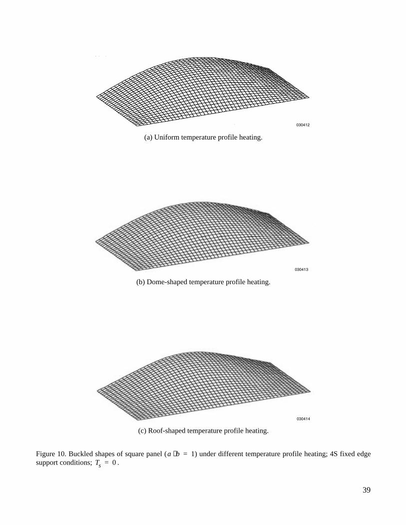
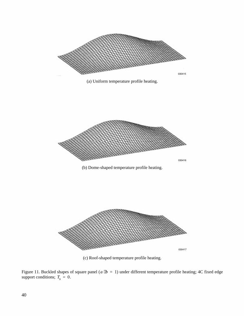
Figures 10 and 11 show the buckled shapes of the isotropic square panel (a/b = 1) under different temperatureprofile loading and under different boundary conditions. Notice that the panel buckling shapes are insensitive tothe temperature loading functions for each set of edge conditions.
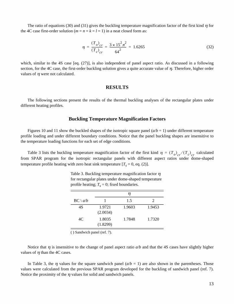
Table 3 lists the buckling temperature magnification factor of the first kind calculatedfrom SPAR program for the isotropic rectangular panels with different aspect ratios under dome-shapedtemperature profile heating with zero heat sink temperature [Ts = 0, eq. (2)].
Notice that η is insensitive to the change of panel aspect ratio a/b and that the 4S cases have slightly highervalues of η than the 4C cases.
In Table 3, the η values for the square sandwich panel (a/b = 1) are also shown in the parentheses. Thosevalues were calculated from the previous SPAR program developed for the buckling of sandwich panel (ref. 7).Notice the proximity of the η values for solid and sandwich panels.
Table 3. Buckling temperature magnification factor η for rectangular plates under dome-shaped temperature profile heating; Ts = 0; fixed boundaries.
η
BC \ a/b 1 1.5 2
4S 1.9721 1.9603 1.9453(2.0034)
4C 1.8035 1.7848 1.7320(1.8299)
( ) Sandwich panel (ref. 7).
ηT o( )
cr
T c( )cr
---------------- 3 152π
2×
642
------------------------ 1.6265= = =
η T o( )cr
T c( )cr
⁄=
14
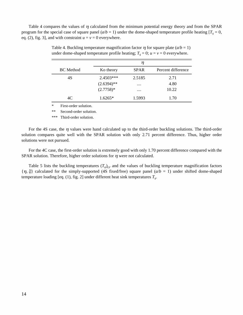
Table 4 compares the values of η calculated from the minimum potential energy theory and from the SPARprogram for the special case of square panel (a/b = 1) under the dome-shaped temperature profile heating [Ts = 0,eq. (2), fig. 3], and with constraint u = v = 0 everywhere.
For the 4S case, the η values were hand calculated up to the third-order buckling solutions. The third-ordersolution compares quite well with the SPAR solution with only 2.71 percent difference. Thus, higher ordersolutions were not pursued.
For the 4C case, the first-order solution is extremely good with only 1.70 percent difference compared with theSPAR solution. Therefore, higher order solutions for η were not calculated.
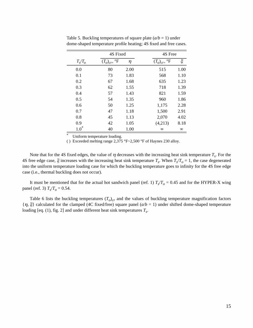
Table 5 lists the buckling temperatures (To)cr and the values of buckling temperature magnification factors{η, ξ} calculated for the simply-supported (4S fixed/free) square panel (a/b = 1) under shifted dome-shapedtemperature loading [eq. (1), fig. 2] under different heat sink temperatures Ts.
Table 4. Buckling temperature magnification factor η for square plate (a/b = 1) under dome-shaped temperature profile heating; Ts = 0; u = v = 0 everywhere.
η
BC Method Ko theory SPAR Percent difference
4S 2.4503*** 2.5185 2.71(2.6394)** .... 4.80(2.7758)* .... 10.22
4C 1.6265* 1.5993 1.70
* First-order solution.
** Second-order solution.
*** Third-order solution.
15
Note that for the 4S fixed edges, the value of η decreases with the increasing heat sink temperature Ts. For the4S free edge case, ξ increases with the increasing heat sink temperature Ts. When Ts/To = 1, the case degeneratedinto the uniform temperature loading case for which the buckling temperature goes to infinity for the 4S free edgecase (i.e., thermal buckling does not occur).
It must be mentioned that for the actual hot sandwich panel (ref. 1) Ts/To = 0.45 and for the HYPER-X wingpanel (ref. 3) Ts/To = 0.54.
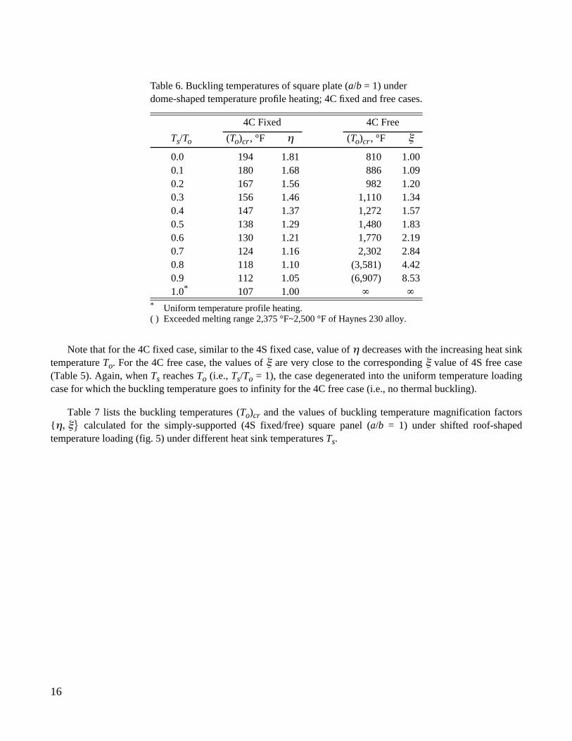
Table 6 lists the buckling temperatures (To)cr and the values of buckling temperature magnification factors{η, ξ} calculated for the clamped (4C fixed/free) square panel (a/b = 1) under shifted dome-shaped temperatureloading [eq. (1), fig. 2] and under different heat sink temperatures Ts.
Table 5. Buckling temperatures of square plate (a/b = 1) underdome-shaped temperature profile heating; 4S fixed and free cases.
4S Fixed 4S Free
Ts/To (To)cr, °F η (To)cr , °F ξ
0.0 80 2.00 515 1.000.1 73 1.83 568 1.100.2 67 1.68 635 1.230.3 62 1.55 718 1.390.4 57 1.43 821 1.590.5 54 1.35 960 1.860.6 50 1.25 1,175 2.280.7 47 1.18 1,500 2.910.8 45 1.13 2,070 4.020.9 42 1.05 (4,213) 8.181.0* 40 1.00
* Uniform temperature loading.( ) Exceeded melting range 2,375 °F~2,500 °F of Haynes 230 alloy.
∞ ∞
16
Note that for the 4C fixed case, similar to the 4S fixed case, value of η decreases with the increasing heat sinktemperature To. For the 4C free case, the values of ξ are very close to the corresponding ξ value of 4S free case(Table 5). Again, when Ts reaches To (i.e., Ts/To = 1), the case degenerated into the uniform temperature loadingcase for which the buckling temperature goes to infinity for the 4C free case (i.e., no thermal buckling).
Table 7 lists the buckling temperatures (To)cr and the values of buckling temperature magnification factors{η, ξ} calculated for the simply-supported (4S fixed/free) square panel (a/b = 1) under shifted roof-shapedtemperature loading (fig. 5) under different heat sink temperatures Ts.
Table 6. Buckling temperatures of square plate (a/b = 1) underdome-shaped temperature profile heating; 4C fixed and free cases.
4C Fixed 4C Free
Ts/To (To)cr , °F η (To)cr , °F ξ
0.0 194 1.81 810 1.000.1 180 1.68 886 1.090.2 167 1.56 982 1.200.3 156 1.46 1,110 1.340.4 147 1.37 1,272 1.570.5 138 1.29 1,480 1.830.6 130 1.21 1,770 2.190.7 124 1.16 2,302 2.840.8 118 1.10 (3,581) 4.420.9 112 1.05 (6,907) 8.531.0* 107 1.00
* Uniform temperature profile heating.( ) Exceeded melting range 2,375 °F~2,500 °F of Haynes 230 alloy.
∞ ∞
17
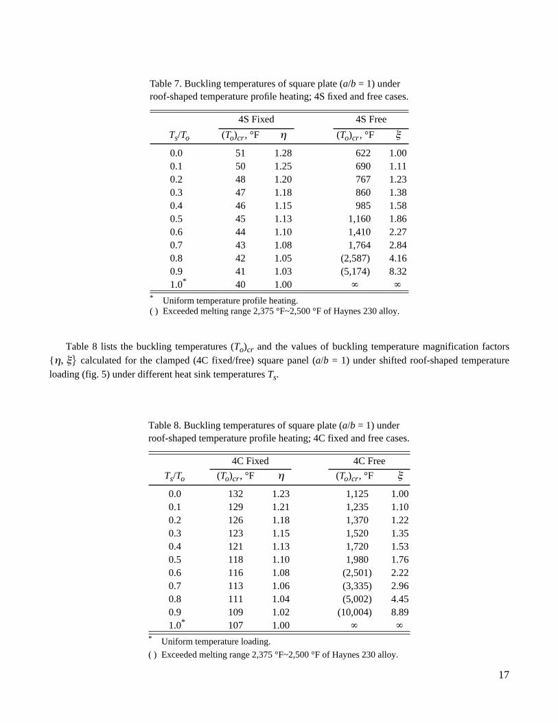
Table 8 lists the buckling temperatures (To)cr and the values of buckling temperature magnification factors{η, ξ} calculated for the clamped (4C fixed/free) square panel (a/b = 1) under shifted roof-shaped temperatureloading (fig. 5) under different heat sink temperatures Ts.
Table 7. Buckling temperatures of square plate (a/b = 1) underroof-shaped temperature profile heating; 4S fixed and free cases.
4S Fixed 4S Free
Ts/To (To)cr , °F η (To)cr , °F ξ
0.0 51 1.28 622 1.000.1 50 1.25 690 1.110.2 48 1.20 767 1.230.3 47 1.18 860 1.380.4 46 1.15 985 1.580.5 45 1.13 1,160 1.860.6 44 1.10 1,410 2.270.7 43 1.08 1,764 2.840.8 42 1.05 (2,587) 4.160.9 41 1.03 (5,174) 8.321.0* 40 1.00
* Uniform temperature profile heating.( ) Exceeded melting range 2,375 °F~2,500 °F of Haynes 230 alloy.
Table 8. Buckling temperatures of square plate (a/b = 1) underroof-shaped temperature profile heating; 4C fixed and free cases.
4C Fixed 4C Free
Ts/To (To)cr, °F η (To)cr, °F ξ
0.0 132 1.23 1,125 1.000.1 129 1.21 1,235 1.100.2 126 1.18 1,370 1.220.3 123 1.15 1,520 1.350.4 121 1.13 1,720 1.530.5 118 1.10 1,980 1.760.6 116 1.08 (2,501) 2.220.7 113 1.06 (3,335) 2.960.8 111 1.04 (5,002) 4.450.9 109 1.02 (10,004) 8.891.0* 107 1.00
* Uniform temperature loading.
( ) Exceeded melting range 2,375 °F~2,500 °F of Haynes 230 alloy.
∞ ∞
∞ ∞
18
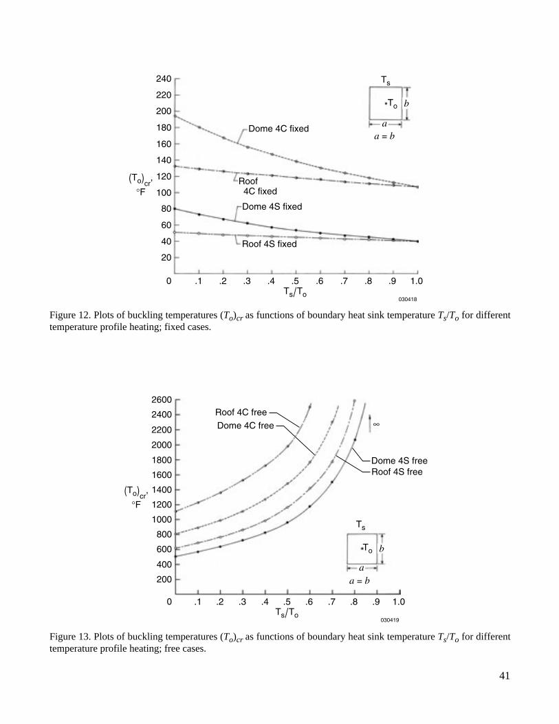
Figures 12 and 13, respectively, show the buckling temperatures (To)cr (data from tables 5–8) plotted asfunctions of normalized heat sink temperature Ts/To for the fixed and free edge cases to illustrate entirely differentbuckling behavior of the fixed and free edge cases. Note from figure 12 that for the fixed edges, the bucklingtemperatures of the roof-shaped temperature profile case are much lower than the dome-shaped temperature profilecase for each panel support condition. However, for the free edges (fig. 13), the reverse is true.
Figure 14 shows the buckling temperature magnification factors {η, ξ} (data from tables 5–8) plotted asfunctions of normalized heat sink temperature Ts/To for easy visualization of the shapes of {η, ξ} curves. Note thatη values for the roof case are much lower than the dome case for the same support condition. For the free edgecases, the ξ curves for different loading and edge support conditions stay very close.
In-Plane Deformations
When the panel is constrained only at the four boundaries, the panel interior points can have in-plane freemotions if the temperature loading is nonuniform. Figure 15 shows the in-plane deformed shapes of the squarepanel under dome-shaped [fig. 15(a)] and roof-shaped [fig.15(b)] temperature loading cases. As expected, thepanel center regions expand more than the panel boundary regions as the result of heating temperature profiles.Figures 16 and 17, respectively, show the distributions of in-plane displacements u(x,y) and v(x,y) for thedome-shaped temperature loading. Note that {u, v} reach a maximum at points between the panel center and theboundaries. For the roof-shaped temperature profile case (figs. 18 and 19), the maximum points of {u, v} migratedtoward the panel center.
Thermal Stresses
Figures 20 and 21, respectively, show the compressive thermal stresses { , } induced in a fixed squarepanel (a/b = 1) under the unit dome-shaped temperature profile heating [To = 1 °F, Ts = 0; eq. (2), fig. 3]. Eventhough the loading temperature profile is dome shaped, the distributions of thermal stresses { , } areairplane-hanger shaped because and within the fixed boundaries. Figure 22 shows thedistribution of shear stress τxy which is wavy shaped. The peak magnitudes of the shear stress occur at theboundaries and near the panel corners.
For the roof-shaped temperature profile heating (To = 1 °F, Ts = 0) (fig. 6), the distributions of { , } areroughly trapezoidal hanger-shaped (figs. 23 and 24). The shear stress distribution (fig. 25) exhibits zero shearstress near the panel center region and a maximum shear near each panel corner.
If the in-plane displacements {u, v} are constrained everywhere in the panel including the edges[i.e., u(x,y) = v(x,y) = 0], the resulting distributions of the biaxial stresses { , } will be dome-shaped just likethe input dome temperature distribution (figs. 26 and 27), and the in-plane shear stress τxy diminishes (τxy = 0). Forthe case of roof-shaped temperature profile (figs. 28 and 29), the distributions of the biaxial stresses { , }reflect the input temperature profile.
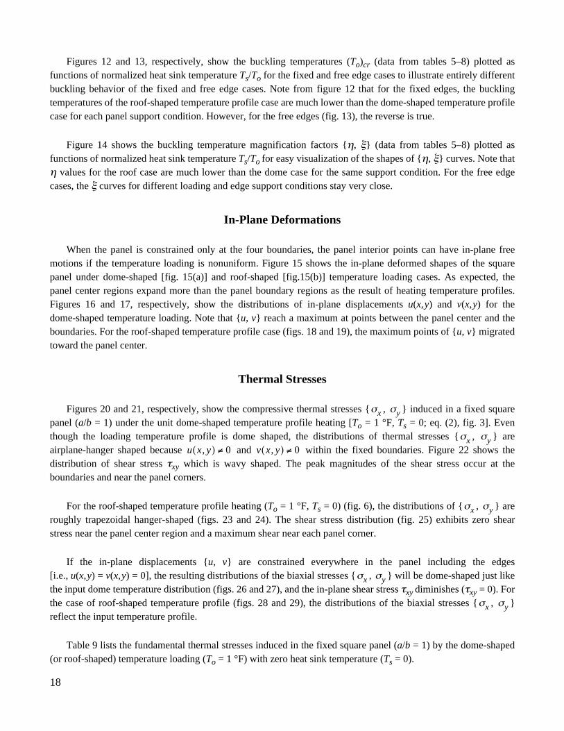
Table 9 lists the fundamental thermal stresses induced in the fixed square panel (a/b = 1) by the dome-shaped(or roof-shaped) temperature loading (To = 1 °F) with zero heat sink temperature (Ts = 0).
σx σy
σx σyu x y,( ) 0≠ v x y,( ) 0≠
σx σy
σx σy
σx σy
19
Note that by setting u(x,y) = v(x,y) = 0 everywhere in the panel including the boundaries, the peak magnitudesof the biaxial stresses {σx, σy} were raised respectively by 59 percent and 20 percent for the dome- androof-shaped temperature profile cases.
CONCLUDING REMARKS
Thermal buckling characteristics of rectangular panels subjected to dome-shaped and roof-shaped temperatureprofile heating were investigated using the finite-element method and the minimum potential energy method. Thekey results include:
1. “Buckling temperature magnification factor of the first kind, η” was established to scale up the bucklingsolution of uniform temperature loading case to give the buckling solution of the dome-shaped (orroof-shaped) temperature loading cases. Also, “buckling temperature magnification factor of the secondkind, ξ” was established to scale up the buckling solution of dome temperature loading case with unheatedboundary heat sinks to give the buckling solutions when the boundary heat sinks are heated up.
2. For the fixed boundary cases when the panel interior in-plane motions are not constrained ( , except boundaries), the panel buckling temperatures under dome-shaped temperature loading arepractically twice the buckling temperatures of the uniform temperature loading cases.
3. For simply-supported case (4S fixed, u = v = 0 everywhere) under the dome-shaped temperature profileheating, the third-order solution of the “buckling temperature magnification factor of the first kind, η”calculated from the minimum potential energy theory, agrees fairly well with the η value calculated fromthe finite-element method. The solution difference is only 2.71 percent.
4. For the clamped case (4C fixed, u = v = 0 everywhere) under dome-shaped temperature profile heating, thefirst-order solution of minimum potential energy gives quite accurate value of η with only1.70 percentdifference from the finite-element solution.
5. For the fixed boundary case when the panel interior points can have free in-plane motions ( , except boundaries), the distribution profiles of the compressive stresses {σx, σy} under the dome-shaped(or roof-shaped) temperature loading have airplane-hanger-like shapes.
6. For the fixed boundary case when the panel in-plane motions are constrained everywhere (u = v = 0everywhere), the distribution profiles of the compressive stresses {σx, σy} take on the dome shape (or roofshape) similar to the input dome-shaped (or roof-shaped) temperature profile.
7. The “buckling temperature magnification factor of the first kind, η” associated with the dome-shapedtemperature profile heating is much greater than that for the roof-shaped temperature profile heating casefor both 4S and 4C fixed edge conditions.
Table 9. Peak thermal stresses {σx, σy, τxy} induced in square plate (a/b = 1) underdome-shaped and roof-shaped temperature loads; To = 1 °F; Ts = 0; fixed boundaries.
Constraints of {u, v} Heating σx, lb/in2 σy, lb/in2 τxy, lb/in2
u = 0, v = 0, edges only Dome –189.26 –189.26 31.27Roof –256.38 –256.38 48.66
u = 0, v = 0, everywhere Dome –301.05 –301.05 0.00Roof –306.77 –306.77 0.00
u 0≠ v 0≠
u 0≠ v 0≠

20
8. The “buckling temperature magnification factor of the second kind, ξ” associated with the dome-shapedand roof-shaped temperature profile heating are very close for 4S and 4C free edge conditions.
Dryden Flight Research CenterNational Aeronautics and Space AdministrationEdwards, California, April 3, 2002
21
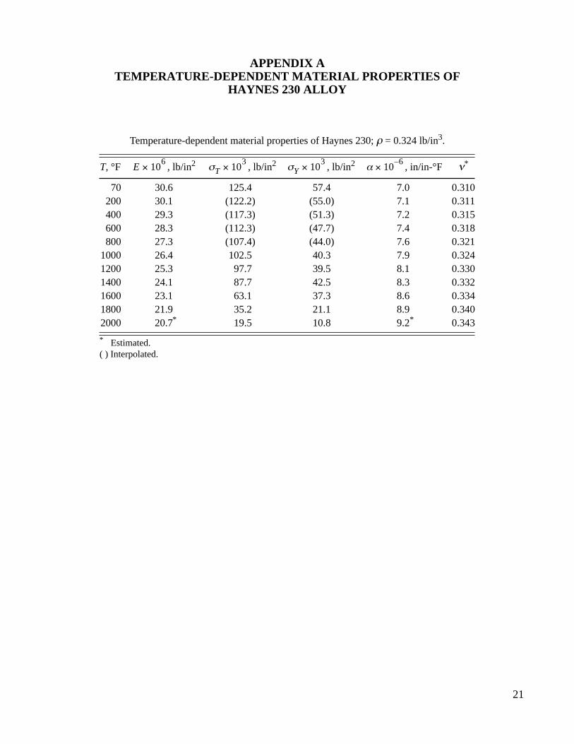
APPENDIX ATEMPERATURE-DEPENDENT MATERIAL PROPERTIES OF
HAYNES 230 ALLOY
Temperature-dependent material properties of Haynes 230; ρ = 0.324 lb/in3.
T, °F , lb/in2 , lb/in2 , lb/in2 , in/in-°F ν*
70 30.6 125.4 57.4 7.0 0.310200 30.1 (122.2) (55.0) 7.1 0.311400 29.3 (117.3) (51.3) 7.2 0.315600 28.3 (112.3) (47.7) 7.4 0.318800 27.3 (107.4) (44.0) 7.6 0.321
1000 26.4 102.5 40.3 7.9 0.3241200 25.3 97.7 39.5 8.1 0.3301400 24.1 87.7 42.5 8.3 0.3321600 23.1 63.1 37.3 8.6 0.3341800 21.9 35.2 21.1 8.9 0.3402000 20.7* 19.5 10.8 9.2* 0.343
* Estimated.( ) Interpolated.
E 106
× σT 103
× σY 103
× α 106–
×

22
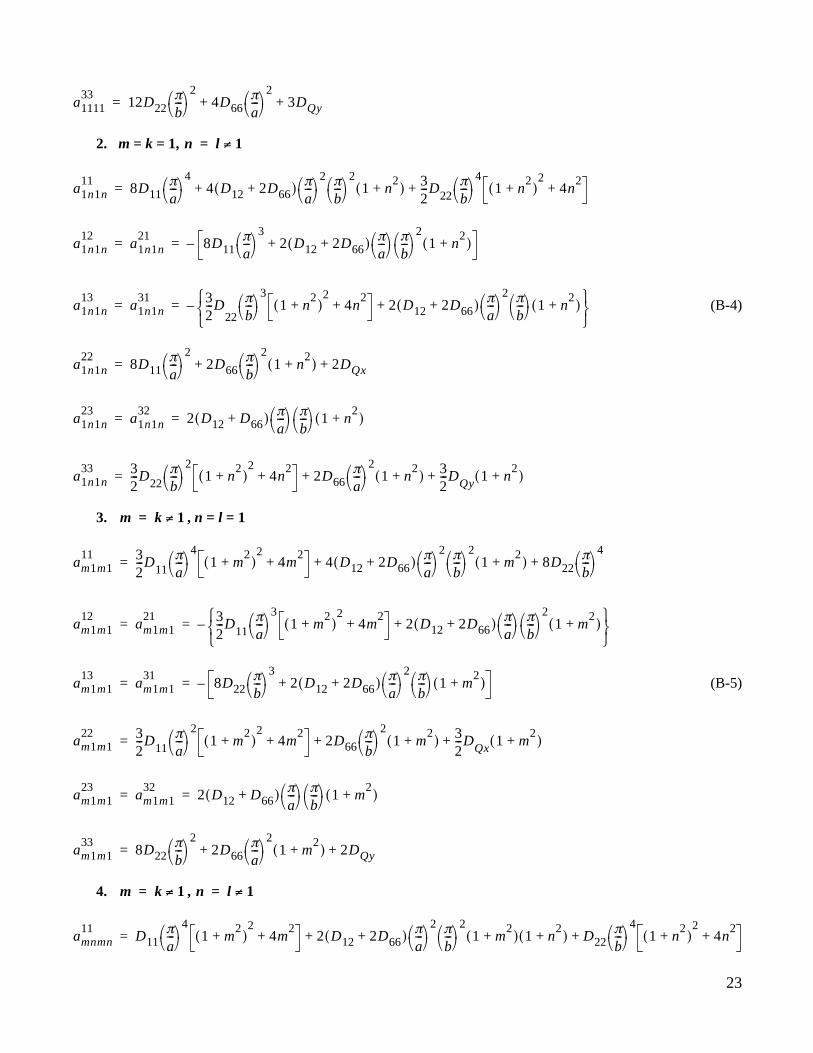
APPENDIX BCOEFFICIENTS OF CHARACTERISTIC EQUATIONS
The characteristic coefficients appearing in equation (20) are defined in the following for differentindicial and edge conditions (refs. 6, 7).
Case 1: 4S condition
1. m = k, n = l
(B-1)
2. ,
(B-2)
Case 2: 4C condition
1. m = n = k = l = 1
(B-3)
amnklij
amnmn11
D11mπa
------- 4
2 D12 2D66+( ) mπa
------- 2 nπ
b------ 2
D22nπb
------ 4
+ +=
amnmn12
amnmn21
D11mπa
------- 3
D12 2D66+( ) mπa
------- nπ
b------ 2
+–= =
amnmn13
amnmn31
D22nπb
------ 3
D12 2D66+( ) mπa
------- 2 nπ
b------ +–= =
amnmn22
D11mπa
------- 2
D66nπb
------ 2
DQx+ +=
amnmn23
amnmn32
D12 D66+( ) mπa
------- nπ
b------ = =
amnmn33
D22nπb
------ 2
D66mπa
------- 2
DQy+ +=
m k≠ n l≠
amnklij
0=
a111111
12D11πa--- 4
8 D12 2D66+( ) πa--- 2 π
b--- 2
12D22πb--- 4
+ +=
a111112
a111121
12D11πa--- 3
4 D12 2D66+( ) πa--- π
b--- 2
+–= =
a111113
a111131
12D22πb--- 3
4 D12 2D66+( ) πa--- 2 π
b--- +–= =
a111122
12D11πa--- 2
4D66πb--- 2
3DQx+ +=
a111123
a111132
4 D12 D66+( ) πa--- π
b--- = =
23
2. m = k = 1,
(B-4)
3. , n = l = 1
(B-5)
4. ,
a111133
12D22πb--- 2
4D66πa--- 2
3DQy+ +=
n l 1≠=
a1n1n11
8D11πa--- 4
4 D12 2D66+( ) πa--- 2 π
b--- 2
1 n2
+( ) 32---D22
πb--- 4
1 n2
+( )2
4n2
++ +=
a1n1n12
a1n1n21
8D11πa--- 3
2 D12 2D66+( ) πa--- π
b--- 2
1 n2
+( )+–= =
a1n1n13
a1n1n31 3
2---D
22
πb--- 3
1 n2
+( )2
4n2
+ 2 D12 2D66+( ) πa--- 2 π
b--- 1 n
2+( )+
–= =
a1n1n22
8D11πa--- 2
2D66πb--- 2
1 n2
+( ) 2DQx+ +=
a1n1n23
a1n1n32
2 D12 D66+( ) πa--- π
b--- 1 n
2+( )= =
a1n1n33 3
2---D22
πb--- 2
1 n2
+( )2
4n2
+ 2D66πa--- 2
1 n2
+( ) 32---D
Qy1 n
2+( )+ +=
m k 1≠=
am1m111 3
2---D11
πa--- 4
1 m2
+( )2
4m2
+ 4 D12 2D66+( ) πa--- 2 π
b--- 2
1 m2
+( ) 8D22πb--- 4
+ +=
am1m112
am1m121 3
2---D11
πa--- 3
1 m2
+( )2
4m2
+ 2 D12 2D66+( ) πa--- π
b--- 2
1 m2
+( )+
–= =
am1m113
am1m131
8D22πb--- 3
2 D12 2D66+( ) πa--- 2 π
b--- 1 m
2+( )+–= =
am1m122 3
2---D11
πa--- 2
1 m2
+( )2
4m2
+ 2D66πb--- 2
1 m2
+( ) 32---D
Qx1 m
2+( )+ +=
am1m123
am1m132
2 D12 D66+( ) πa--- π
b--- 1 m
2+( )= =
am1m133
8D22πb--- 2
2D66πa--- 2
1 m2
+( ) 2DQy+ +=
m k 1≠= n l 1≠=
amnmn11
D11πa--- 4
1 m2
+( )2
4m2
+ 2 D12 2D66+( ) πa--- 2 π
b--- 2
1 m2
+( ) 1 n2
+( ) D22πb--- 4
1 n2
+( )2
4n2
++ +=
24
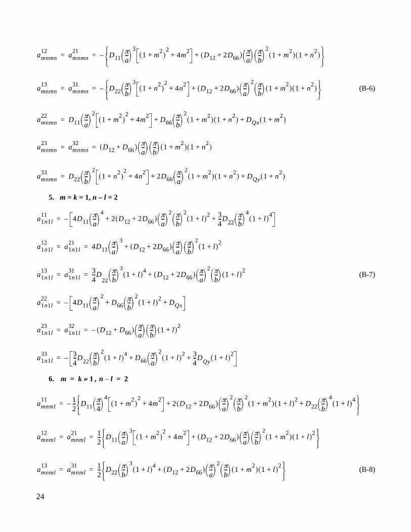
(B-6)
5. m = k = 1, n – l = 2
(B-7)
6. ,
(B-8)
amnmn12
amnmn21
D11πa--- 3
1 m2
+( )2
4m2
+ D12 2D66+( ) πa--- π
b--- 2
1 m2
+( ) 1 n2
+( )+
–= =
amnmn13
amnmn31
D22πb--- 3
1 n2
+( )2
4n2
+ D12 2D66+( ) πa--- 2 π
b--- 1 m
2+( ) 1 n
2+( )+
–= =
amnmn22
D11πa--- 2
1 m2
+( )2
4m2
+ D66πb--- 2
1 m2
+( ) 1 n2
+( ) DQx 1 m2
+( )+ +=
amnmn23
amnmn32
D12 D66+( ) πa--- π
b--- 1 m
2+( ) 1 n
2+( )= =
amnmn33
D22πb--- 2
1 n2
+( )2
4n2
+ 2D66πa--- 2
1 m2
+( ) 1 n2
+( ) DQy 1 n2
+( )+ +=
a1n1l11
4D11πa--- 4
2 D12 2D66+( ) πa--- 2 π
b--- 2
1 l+( )2 3
4---D22
πb--- 4
1 l+( )4
+ +–=
a1n1l12
a1n1l21
4D11πa--- 3
D12 2D66+( ) πa--- π
b--- 2
1 l+( )2
+= =
a1n1l13
a1n1l31 3
4---D
22
πb--- 3
1 l+( )4
D12 2D66+( ) πa--- 2 π
b--- 1 l+( )
2+= =
a1n1l22
4D11πa--- 2
D66πb--- 2
1 l+( )2
DQx+ +–=
a1n1l23
a1n1l32
D12 D66+( )– πa--- π
b--- 1 l+( )
2= =
a1n1l33 3
4---D22
πb--- 2
1 l+( )4
D66πa--- 2
1 l+( )2 3
4---D
Qy1 l+( )
2+ +–=
m k 1≠= n l– 2=
amnml11 1
2---– D11
π4--- 4
1 m2
+( )2
4m2
+ 2 D12 2D66+( ) πa--- 2 π
b--- 2
1 m2
+( ) 1 l+( )2
D22πb--- 4
1 l+( )4
+ +
=
amnml12
amnml21 1
2--- D11
πa--- 3
1 m2
+( )2
4m2
+ D12 2D66+( ) πa--- π
b--- 2
1 m2
+( ) 1 l+( )2
+
= =
amnml13
amnml31 1
2--- D22
πb--- 3
1 l+( )4
D12 2D66+( ) πa--- 2 π
b--- 1 m
2+( ) 1 l+( )
2+
= =

25
7. m – k = 2, n = l = 1
(B-9)
8. m – k = 2,
(B-10)
amnml22 1
2---– D11
πa--- 2
1 m2
+( )2
4m2
+ D66πb--- 2
1 m2
+( ) 1 l+( )2
DQx 1 m2
+( )+ +
=
amnml23
amnml32 1
2--- D12 D66+( )– π
a--- π
b--- 1 m
2+( ) 1 l+( )
2= =
amnml33 1
2--- D22
πb--- 2
1 l+( )4
D66πa--- 2
1 m2
+( ) 1 l+( )2
DQy 1 l+( )2
+ +–=
am1k111 3
4---D11
πa--- 4
1 k+( )4
2 D12 2D66+( ) πa--- 2 π
b--- 2
1 k+( )2
4D22πb--- 4
+ +–=
am1k112
am1k121 3
4---D11
πa--- 3
1 k+( )4
D12 2D66+( ) πa--- π
b--- 2
1 k+( )2
+= =
am1k113
am1k131
4D22πb--- 3
D12 2D66+( ) πa--- 2 π
b--- 1 k+( )
2+= =
am1k122 3
4---D11
πa--- 2
1 k+( )4
D66πb--- 2
1 k+( )2 3
4---D
Qx1 k+( )
2+ +–=
am1k123
am1k132
D12 D66+( )– πa--- π
b--- 1 k+( )
2= =
am1k133
4D22πb--- 2
D66πa--- 2
1 k+( )2
DQy+ +–=
n l 1≠=
amnkn11 1
2--- D11
πa--- 4
1 k+( )4
2 D12 2D66+( ) πa--- 2 π
b--- 2
1 k+( )2
1 n2
+( ) D22πb--- 4
1 n2
+( )2
4n2
++ +
–=
amnkn12
amnkn21 1
2--- D11
πa--- 3
1 k+( )4
D12 2D66+( ) πa--- π
b--- 2
1 k+( )2
1 n2
+( )+= =
amnkn13
amnkn31 1
2--- D22
πb--- 3
1 n2
+( )2
4n2
+ D12 2D66+( ) πa--- 2 π
b--- 1 k+( )
21 n
2+( )+= =
amnkn22 1
2--- D11
πa--- 2
1 k+( )4
D66πb--- 2
1 k+( )2
1 n2
+( ) DQx 1 k+( )2
+ +–=
amnkn23
amnkn32 1
2--- D12 D66+( )– π
a--- π
b--- 1 k+( )
21 n
2+( )= =
amnkn33 1
2--- D22
πb--- 2
1 n2
+( )2
4n2
+ D66πa--- 2
1 k+( )2
1 n2
+( ) DQy 1 n2
+( )+ +
–=

26
9. m – k = 2, n – l = 2
(B-11)
amnkl11 1
4--- D11
πa--- 4
1 k+( )4
2 D12 2D66+( ) πa--- 2 π
b--- 2
1 k+( )2
1 l+( )2
D22πb--- 4
1 l+( )4
+ +=
amnkl12
amnkl21 1
4---– D11
πa--- 3
1 k+( )4
D12 2D66+( ) πa--- π
b--- 2
1 k+( )2
1 l+( )2
+= =
amnkl13
amnkl31 1
4---– D22
πb--- 3
1 l+( )4
D12 2D66+( ) πa--- 2 π
b--- 1 k+( )
21 l+( )
2+= =
amnkl22 1
4--- D11
πa--- 2
1 k+( )4
D66πb--- 2
1 k+( )2
1 l+( )2
DQx 1 k+( )2
+ +=
amnkl23
amnkl32 1
4--- D12 D66+( ) π
a--- π
b--- 1 k+( )
21 l+( )
2= =
amnkl33 1
4--- D22
πb--- 2
1 l+( )4
D66πa--- 2
1 k+( )2
1 l+( )2
DQy 1 l+( )2
+ +=

27
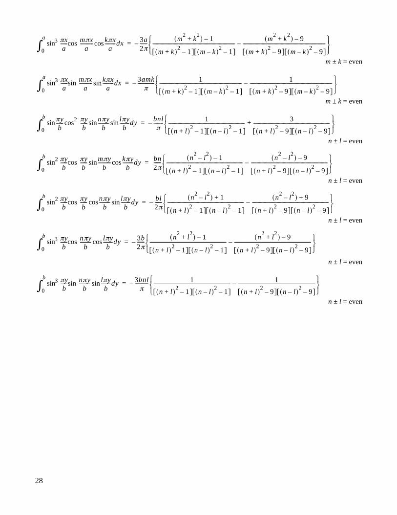
APPENDIX CTABLE OF SPECIAL INTEGRALS
Different types of integrals are needed to carry out the integration of strain energy expression associated withthe dome-shaped temperature profile heating.
Special Integrals Needed for 4S Case:
; m = k
; n = l
; m ± k = even
; n ± l = even
Special Integrals Needed for 4C Case:
m ± k = even
m ± k = even
m ± k = even
mπxa
-----------cos0
a
∫kπx
a---------dxcos a
2---=
nπyb
---------cos0
b
∫lπyb
--------cos dy b2---=
mπxa
-----------sin0
a
∫kπx
a---------sin πx
a------sin dx 4a
π------– mk
m k+( )2
1–[ ] m k–( )2
1–[ ]---------------------------------------------------------------------=
nπyb
---------sin0
b
∫lπyb
--------sin πyb
------sin dy 4bπ
------– nl
n l+( )2
1–[ ] n l–( )2
1–[ ]----------------------------------------------------------------=
πxa
------sin0
a
∫πxa
------2cos mπxa
-----------sin kπxa
---------sin dx amkπ
----------– 1
m k+( )2
1–[ ] m k–( )2
1–[ ]--------------------------------------------------------------------- 3
m k+( )2
9–[ ] m k–( )2
9–[ ]---------------------------------------------------------------------+
=
πxa
------sin2
0
a
∫πxa
------cos mπxa
-----------sin kπxa
---------cos dx am2π-------
m2
k2
–( ) 1–
m k+( )2
1–[ ] m k–( )2
1–[ ]---------------------------------------------------------------------
m2
k2
–( ) 9–
m k+( )2
9–[ ] m k–( )2
9–[ ]---------------------------------------------------------------------–
=
πxa
------sin2
0
a
∫πxa
------cos mπxa
-----------cos kπxa
---------sin dx ak2π------–
m2
k2
–( ) 1+
m k+( )2
1–[ ] m k–( )2
1–[ ]---------------------------------------------------------------------
m2
k2
–( ) 9+
m k+( )2
9–[ ] m k–( )2
9–[ ]---------------------------------------------------------------------–
=
28
m ± k = even
m ± k = even
n ± l = even
n ± l = even
n ± l = even
n ± l = even
n ± l = even
πxa
------sin3
0
a
∫mπx
a-----------cos kπx
a---------cos dx 3a
2π------–
m2
k2
+( ) 1–
m k+( )2
1–[ ] m k–( )2
1–[ ]---------------------------------------------------------------------
m2
k2
+( ) 9–
m k+( )2
9–[ ] m k–( )2
9–[ ]---------------------------------------------------------------------–
=
πxa
------sin3
0
a
∫mπx
a-----------sin kπx
a---------sin dx 3amk
π--------------– 1
m k+( )2
1–[ ] m k–( )2
1–[ ]--------------------------------------------------------------------- 1
m k+( )2
9–[ ] m k–( )2
9–[ ]---------------------------------------------------------------------–
=
πyb
------sin0
b
∫πyb
------2cos nπyb
---------sin lπyb
--------sin dy bnlπ
--------– 1
n l+( )2
1–[ ] n l–( )2
1–[ ]---------------------------------------------------------------- 3
n l+( )2
9–[ ] n l–( )2
9–[ ]----------------------------------------------------------------+
=
πyb
------sin2
0
b
∫πyb
------cos mπyb
-----------sin kπyb
---------cos dy bn2π------
n2
l2
–( ) 1–
n l+( )2
1–[ ] n l–( )2
1–[ ]----------------------------------------------------------------
n2
l2
–( ) 9–
n l+( )2
9–[ ] n l–( )2
9–[ ]----------------------------------------------------------------–
=
πyb
------sin2
0
b
∫πyb
------cos nπyb
---------cos lπyb
--------sin dy bl2π------–
n2
l2
–( ) 1+
n l+( )2
1–[ ] n l–( )2
1–[ ]----------------------------------------------------------------
n2
l2
–( ) 9+
n l+( )2
9–[ ] n l–( )2
9–[ ]----------------------------------------------------------------–
=
πyb
------sin3
0
b
∫nπy
b---------cos lπy
b--------cos dy 3b
2π------–
n2
l2
+( ) 1–
n l+( )2
1–[ ] n l–( )2
1–[ ]----------------------------------------------------------------
n2
l2
+( ) 9–
n l+( )2
9–[ ] n l–( )2
9–[ ]----------------------------------------------------------------–
=
πyb
------sin3
0
b
∫nπy
b---------sin lπy
b--------sin dy 3bnl
π-----------– 1
n l+( )2
1–[ ] n l–( )2
1–[ ]---------------------------------------------------------------- 1
n l+( )2
9–[ ] n l–( )2
9–[ ]----------------------------------------------------------------–
=
29
Case 1: 4S condition
m ± n = even (symmetric buckling)
Akl→ A11 A13 A22 A31 A15 A24 A33 A42 A51 A35 A44 A53
m=1, n=1 P1113 0 P1131 P1115 0 P1133 0 P1151 P1135 0 P1153
m=1, n=3 0 P1331 P1315 0 P1333 0 P1351 P1335 0 P1353
m=2, n=2 0 0 P2224 0 P2242 0 0 P2244 0
m=3, n=1 P3115 0 P3133 0 P3151 P3135 0 P3133
m=1, n=5 0 P1533 0 P1551 P1535 0 P1553
m=2, n=4 0 P2442 0 0 P2444 0 = 0
m=3, n=3 0 P3351 P3335 0 P3353
m=4, n=2 Symmetry 0 0 P4244 0
m=5, n=1 P5135 0 P5153
m=3, n=5 0 P3553
m=4, n=4 0
m=5, n=3
M1111T o
----------------- P1111+
M1313T o
----------------- P1313+
M2222T o
----------------- P2222+
M3131T o
----------------- P3131+
M1515T o
----------------- P1515+
M2424T o
----------------- P2424+
M3333T o
----------------- P3333+
M4242T o
----------------- P4242+
M5151T o
----------------- P5151+
M3535T o
----------------- P3535+
M4444T o
----------------- P4444+
M5353T o
----------------- P5353+
(D-1)
APPENDIX DBUCKLING EQUATIONS
30
Case 1: 4S condition
m ± n = odd (antisymmetric buckling)
Akl→ A12 A21 A14 A23 A32 A41 A16 A25 A34 A43 A52 A61
m=1, n=2 0 P1214 0 P1232 0 P1216 0 P1234 0 P1252 0
m=2, n=1 0 P2123 0 P2141 0 P2125 0 P2143 0 P2161
m=1, n=4 0 P1432 0 P1416 0 P1434 0 P1452 0
m=2, n=3 0 P2341 0 P2325 0 P2343 0 P2361
m=3, n=2 0 P3216 0 P3234 0 P3252 0
m=4, n=1 0 P4125 0 P4143 0 P4161 = 0
m=1, n=6 0 P1634 0 P1652 0
m=2, n=5 Symmetry 0 P2543 0 P2561
m=3, n=4 0 P3452 0
m=4, n=3 0 P4361
m=5, n=2 0
m=6, n=1
M1212T o
----------------- P1212+
M2121T o
----------------- P2121+
M1414T o
----------------- P1414+
M2323T o
----------------- P2323+
M3232T o
----------------- P3232+
M4141T o
----------------- P4141+
M1616T o
----------------- P1616+
M2525T o
----------------- P2525+
M3434T o
----------------- P3434+
M4343T o
----------------- P4343+
M5252T o
----------------- P5252+
M6161T o
----------------- P6161+
(D-2)
31
Case 2: 4C condition
m ± n = even (symmetric buckling)
Akl→ A11 A13 A22 A31 A15 A24 A33 A42 A51 A35 A44 A53
m=1, n=1 0 P1115 0 0 P1151 P1135 0 P1153
m=1, n=3 0 0 0 P1351 0 P1353
m=2, n=2 0 0 0 0 0 0
m=3, n=1 P3115 0 0 P3135 0
m=1, n=5 0 0 P1551 0 P1553
m=2, n=4 0 0 0 = 0
m=3, n=3 0 0
m=4, n=2 Symmetry 0 0 0
m=5, n=1 P5135 0
m=3, n=5 0
m=4, n=4 0
m=5, n=3
M1111T o
----------------- P1111+M1113
T o----------------- P1113+
M1131T o
----------------- P1131+M1133
T o----------------- P1133+
M1313T o
----------------- P1313+M1331
T o----------------- P1331+
M1315T o
----------------- P1315+M1333
T o----------------- P1333+
M1335T o
----------------- P1335+
M2222T o
----------------- P2222+M2224
T o----------------- P2224+
M2242T o
----------------- P2242+M2244
T o----------------- P2244+
M3131T o
----------------- P3131+M3133
T o----------------- P3133+
M3151T o
----------------- P3151+M3153
T o----------------- P3153+
M1515T o
----------------- P1515+M1533
T o----------------- P1533+
M1535T o
----------------- P1535+
M2424T o
----------------- P2424+M2442
T o----------------- P2442+
M2444T o
----------------- P2444+M2453
T o----------------- P2453+
M3333T o
----------------- P3333+M3351
T o----------------- P3351+
M3335T o
----------------- P3335+M3353
T o----------------- P3353+
M4242T o
----------------- P4242+M4244
T o----------------- P4244+
M5151T o
----------------- P5151+M5153
T o----------------- P5153+
M3535T o
----------------- P3535+M3553
T o----------------- P3553+
M4444T o
----------------- P4444+
M5353T o
----------------- P5353+
(D-3)
32
Case 2: 4C condition
m ± n = odd (antisymmetric buckling)
Akl→ A12 A21 A14 A23 A32 A41 A16 A25 A34 A43 A52 A61
m=1, n=2 0 0 0 P1216 0 0 P1252 0
m=2, n=1 0 0 0 P2125 0 0 P2161
m=1, n=4 0 0 0 0 P1452 0
m=2, n=3 0 0 0 0 P2361
m=3, n=2 0 P3216 0 0 0
m=4, n=1 0 P4125 0 0 = 0
m=1, n=6 0 0 P1652 0
m=2, n=5 Symmetry 0 0 P2561
m=3, n=4 0 0
m=4, n=3 0
m=5, n=2 0
m=6, n=1
M1212T o
----------------- P1212+M1214
T o----------------- P1214+
M1232T o
----------------- P1232+M1234
T o----------------- P1234+
M2121T o
----------------- P2121+M2123
T o----------------- P2123+
M2141T o
----------------- P2141+M2143
T o----------------- P2143+
M1414T o
----------------- P1414+M1432
T o----------------- P1432+
M1416T o
----------------- P1416+M1434
T o----------------- P1434+
M2323T o
----------------- P2323+M2341
T o----------------- P2341+
M2325T o
----------------- P2325+M2343
T o----------------- P2343+
M3232T o
----------------- P3232+M3234
T o----------------- P3234+
M3252T o
----------------- P3252+
M4141T o
----------------- P4141+M4143
T o----------------- P4143+
M4161T o
----------------- P4161+
M1616T o
----------------- P1616+M1634
T o----------------- P1634+
M2525T o
----------------- P2525+M2543
T o----------------- P2543+
M3434T o
----------------- P3434+M3452
T o----------------- P3452+
M4343T o
----------------- P4343+M4361
T o----------------- P4361+
M5252T o
----------------- P5252+
M6161T o
----------------- P6161+
(D-4)
33
REFERENCES
1. Richards, W. Lance and Randolph C. Thompson, “Titanium Honeycomb Panel Testing,” Proceedings,Structural Testing Technology at High Temperature Conference, Dayton, Ohio, Nov. 4–6, 1991, Society forExperimental Mechanics, Inc., 1992, pp. 116–132.
2. Ko, William L., Robert D. Quinn, and Leslie Gong, Finite-Element Reentry Heat-Transfer Analysis of SpaceShuttle Orbiter, NASA TP-2657, 1986.
3. Ko, William L. and Leslie Gong, Thermostructural Analysis of Unconventional Wing Structures of a Hyper-XHypersonic Flight Research Vehicle for the Mach 7 Mission, NASA/TP-2001-210398, 2001.
4. Ko, William L. and Raymond H. Jackson, “Combined Compressive and Shear Buckling Analysis ofHypersonic Aircraft Structural Sandwich Panels,” AIAA Paper No. 92-2487-CP, 33rdAIAA/ASME/ASCE/AHS/ASC Structures, Structural Dynamics and Materials Conference, Dallas, Texas,April 13–15, 1992. Also published as NASA TM-4290, 1991.
5. Ko, William L., “Mechanical and Thermal Buckling Analysis of Sandwich Panels Under Different EdgeConditions,” Proc. 1st Pacific International Conference on Aerospace Science and Technology, Tainan,Taiwan, Dec. 6–9, 1993.
6. Ko, William L. and Raymond H. Jackson, Mechanical and Thermal Bucklings of Rectangular SandwichPanels Under Different Edge Conditions, NASA TM-4585, 1994.
7. Ko, William L., Predictions of Thermal Buckling Strengths of Hypersonic Aircraft Sandwich Panels UsingMinimum Potential Energy and Finite Element Methods, NASA TM-4643, 1995.
8. Ko, William L. and Raymond H. Jackson, Combined-Load Buckling Behavior of Metal-Matrix CompositeSandwich Panels Under Different Thermal Environments, NASA TM-4321, 1991.
9. Ko, William L. and Raymond H. Jackson, “Compressive and Shear Buckling Analysis of Metal MatrixComposite Sandwich Panels Under Different Thermal Environments,” Composite Structures, Vol. 25, 1993,pp. 227–239.
10. Ko, William L., Thermostructural Behavior of a Hypersonic Aircraft Sandwich Panel Subjected to Heatingon One Side, NASA TM-4769, 1997.
11. Whetstone, W. D., SPAR Structural Analysis System Reference Manual, System Level 13A, Vol. 1, ProgramExecution, NASA CR-158970-1, 1978.
12. Ko, William L., Mechanical- and Thermal-Buckling Behavior of Rectangular Plates With Different CentralCutouts, NASA/TM-1998-206542, 1998.
34
FIGURES
030401
24 in.
24 in.
Temperature,°F
500
600
400
300
200
100
0
Figure 1. Measured temperature distribution in upper surface of titanium honeycomb-core sandwich panel, heatedon upper side at 10 °F/sec heating rate, with four edges supported by test fixtures (heat sink) (ref. 1).
030402
Panel centerline
Panel edge
y
a
x
TTo
b/2
Ts
Figure 2. Shifted dome-shaped temperature profile heating ( ).Ts 0≠
35
030403
Panel edge
y
a
x
T
To
b/2
Ts = 0
Figure 3. Dome-shaped temperature profile heating ( ).Ts 0=
030404
Panel centerline
Panel edge
y
x
T
Tc
To = Ts = Tc
b/2 a
Figure 4. Uniform temperature profile heating ( ).To Ts Tc constant= = =
36
030405
b
Rectangularpanel
y
a
x
T
To
Ts
Figure 5. Shifted roof-shaped temperature profile heating ( ).Ts 0≠
030406
Rectangularpanel
y
a
x
T
To
b Ts = 0
Figure 6. Roof-shaped temperature profile heating ( ).Ts 0=
37
030407
Quarter
panel
model
JLOCs
E43 elements
625
576
x, u
y, v
ts
b
z, w
a
Figure 7. Quarter panel finite-element model for rectangular panel.
38
030408
Fixedsupport
030409
Movable support
Lubricated
(a) 4S fixed.
(b) 4S free.
Figure 8. Two types of boundary conditions for simply-supported edges.
030410
Fixedsupport
(a) 4C fixed.
030411
Lubricated
Movable support
(b) 4C free.
Figure 9. Two types of boundary conditions for clamped edges.
39
030413
030414
(a) Uniform temperature profile heating.
(b) Dome-shaped temperature profile heating.
(c) Roof-shaped temperature profile heating.
Figure 10. Buckled shapes of square panel ( ) under different temperature profile heating; 4S fixed edgesupport conditions; .
a b⁄ 1=Ts 0=
40
030415
030416
030417
(c) Roof-shaped temperature profile heating.
Figure 11. Buckled shapes of square panel ( ) under different temperature profile heating; 4C fixed edgesupport conditions; .
a b⁄ 1=Ts 0=
(b) Dome-shaped temperature profile heating.
(a) Uniform temperature profile heating.
41
030418
a = bDome 4C fixed
240
Roof4C fixed
Dome 4S fixed
Roof 4S fixed
b220
200
180
160
140
120
100
80
60
40
20
0 .1 .2 .3 .4 .5Ts/To
(To)cr
,
°F
To
Ts
.6 .7 .8 .9 1.0
a
Figure 12. Plots of buckling temperatures (
T
o
)
cr
as functions of boundary heat sink temperature
T
s
/
T
o
for differenttemperature profile heating; fixed cases.
030419
a = b
Dome 4C free
2600Roof 4C free
Dome 4S freeRoof 4S free
b
2400
2200
2000
1800
1600
1400
1200
1000
800
600
400
200
0 .1 .2 .3 .4 .5Ts/To
(To)cr
,
°F
To
Ts
∞
.6 .7 .8 .9 1.0
a
Figure 13. Plots of buckling temperatures (
T
o
)
cr
as functions of boundary heat sink temperature
T
s
/
T
o
for differenttemperature profile heating; free cases.
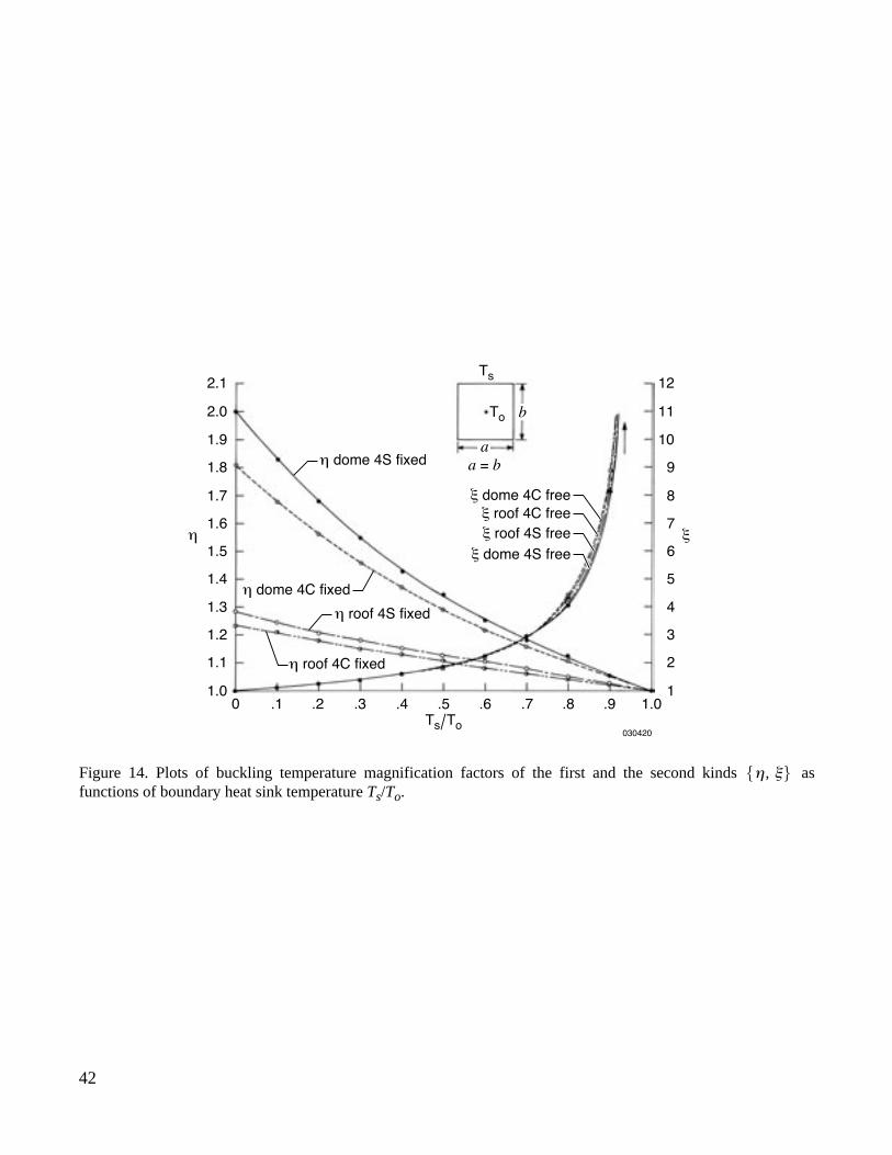
42
030420
a = bh dome 4S fixed
x dome 4C free
x roof 4C free
x roof 4S free
x dome 4S free
h dome 4C fixed
h roof 4S fixed
h x
2.1
b
0 .1 .2 .3 .4 .5
Ts/To
To
Ts
.6 .7 .8 .9 1.0
2.0
1.9
1.8
1.7
1.6
1.5
1.4
1.3
1.2
1.1
1.0
12
11
10
9
8
7
6
5
4
3
2
1
h roof 4C fixed
a
Figure 14. Plots of buckling temperature magnification factors of the first and the second kinds asfunctions of boundary heat sink temperature
T
s
/
T
o
.η ξ,{ }
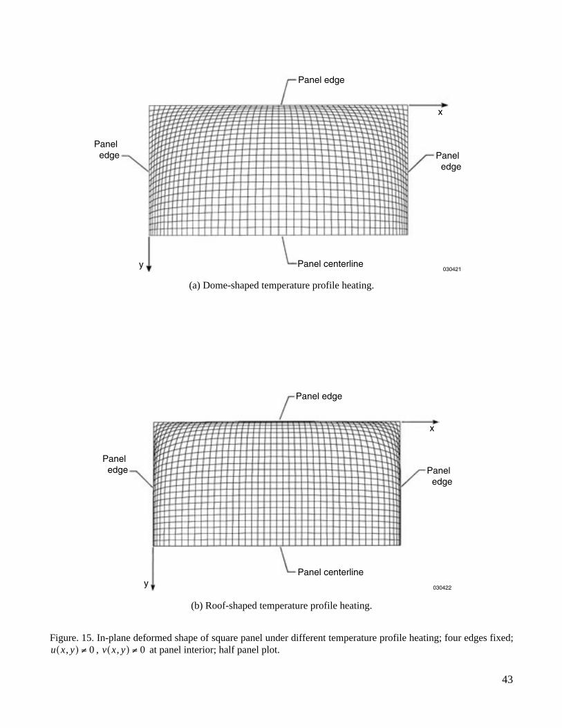
43
030421
Panel edge
Paneledge Panel
edge
Panel centerliney
x
(a) Dome-shaped temperature profile heating.
030422
Panel edge
Paneledge Panel
edge
Panel centerliney
x
(b) Roof-shaped temperature profile heating.
Figure. 15. In-plane deformed shape of square panel under different temperature profile heating; four edges fixed;, at panel interior; half panel plot.u x y,( ) 0≠ v x y,( ) 0≠
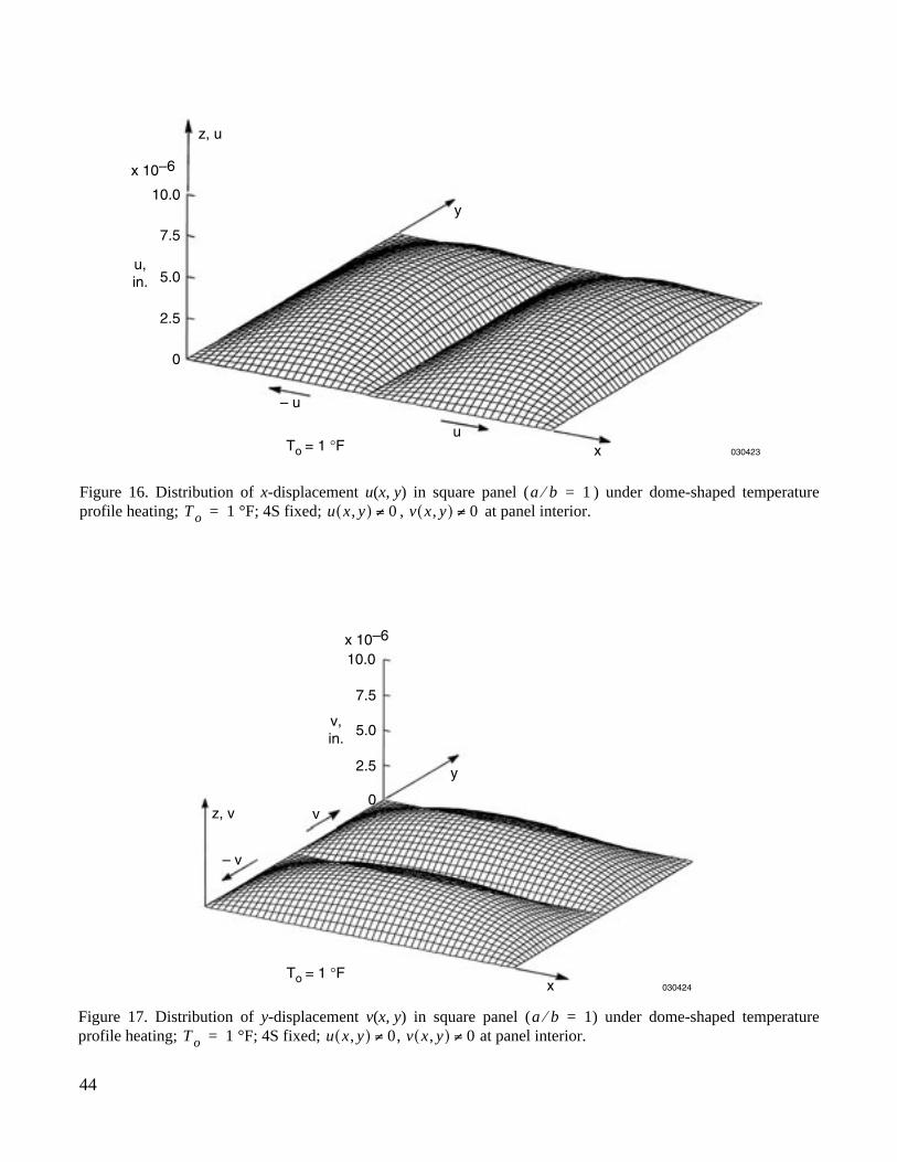
44
030423
0
To = 1 °F
2.5
5.0u,in.
7.5
10.0
x 10–6
y
xu
– u
z, u
Figure 16. Distribution of
x
-displacement
u
(
x
,
y
) in square panel ( ) under dome-shaped temperatureprofile heating; °F; 4S fixed; , at panel interior.
a b⁄ 1=T o 1= u x y,( ) 0≠ v x y,( ) 0≠
030424
0
To = 1 °F
2.5
5.0v,in.
7.5
10.0x 10⁻⁶
y
x
v
– v
z, v
Figure 17. Distribution of
y
-displacement
v
(
x
,
y
) in square panel ( ) under dome-shaped temperatureprofile heating; °F; 4S fixed; , at panel interior.
a b⁄ 1=T o 1= u x y,( ) 0≠ v x y,( ) 0≠
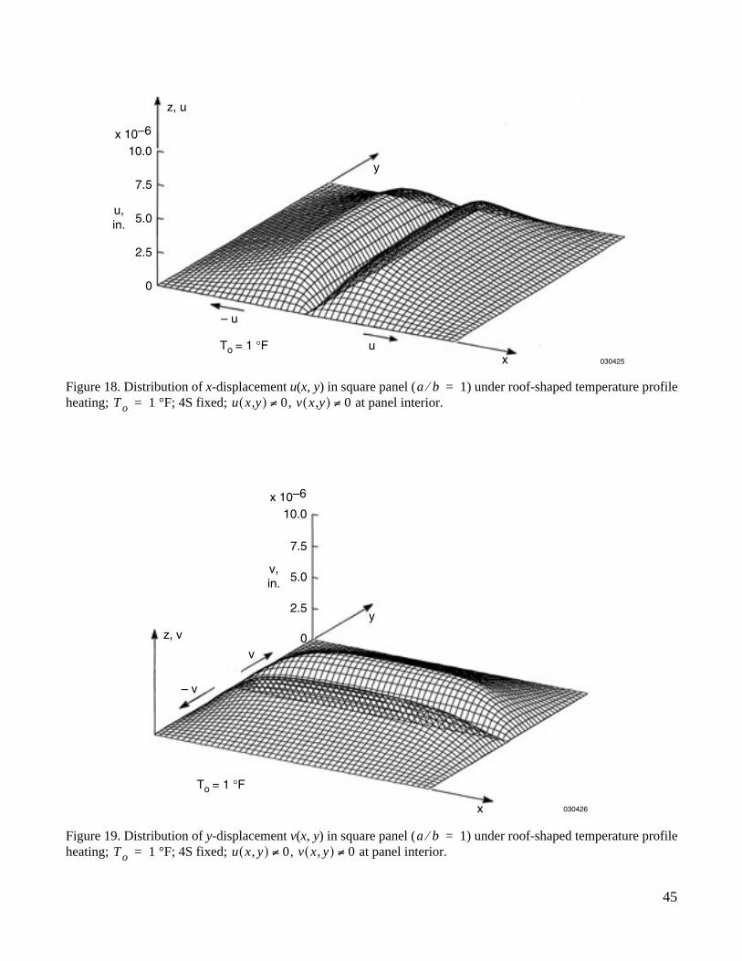
45
030425
0
To = 1 °F
2.5
5.0u,in.
7.5
10.0x 10⁻⁶
y
xu
– u
z, u
Figure 18. Distribution of
x
-displacement
u
(
x
,
y
) in square panel ( ) under roof-shaped temperature profileheating; °F; 4S fixed; , at panel interior.
a b⁄ 1=T o 1= u x y,( ) 0≠ v x y,( ) 0≠
030426
0
To = 1 °F
2.5
5.0v,in.
7.5
10.0x 10⁻⁶
y
x
v
– v
z, v
Figure 19. Distribution of
y
-displacement
v
(
x
,
y
) in square panel ( ) under roof-shaped temperature profileheating; °F; 4S fixed; , at panel interior.
a b⁄ 1=T o 1= u x y,( ) 0≠ v x y,( ) 0≠
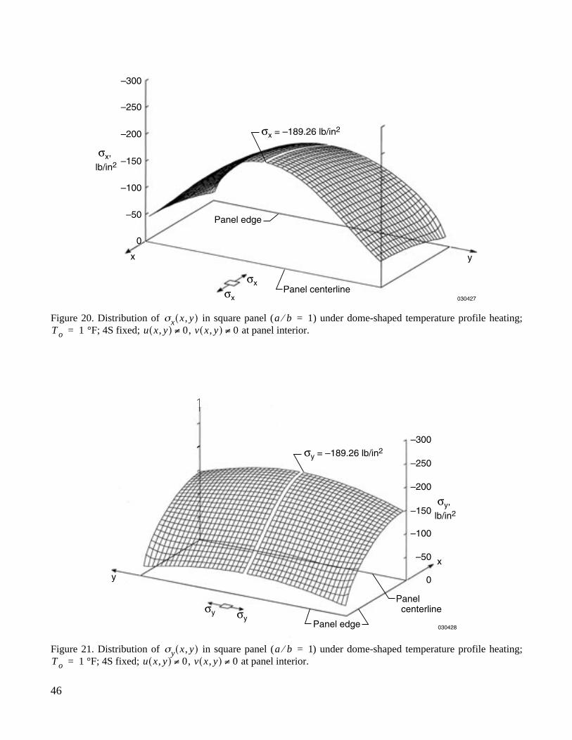
46
030427
–300
σx
σx = –189.26 lb/in2
σx,
lb/in2
σx
Panel edge
yx
Panel centerline
–250
–200
–150
–100
–50
0
Figure 20. Distribution of in square panel ( ) under dome-shaped temperature profile heating; °F; 4S fixed; , at panel interior.
σx x y,( ) a b⁄ 1=T o 1= u x y,( ) 0≠ v x y,( ) 0≠
030428
–300
σy
σy = –189.26 lb/in2
σy,
lb/in2
σy
Panel edge
y
x
Panelcenterline
–250
–200
–150
–100
–50
0
Figure 21. Distribution of in square panel ( ) under dome-shaped temperature profile heating; °F; 4S fixed; , at panel interior.
σy x y,( ) a b⁄ 1=T o 1= u x y,( ) 0≠ v x y,( ) 0≠
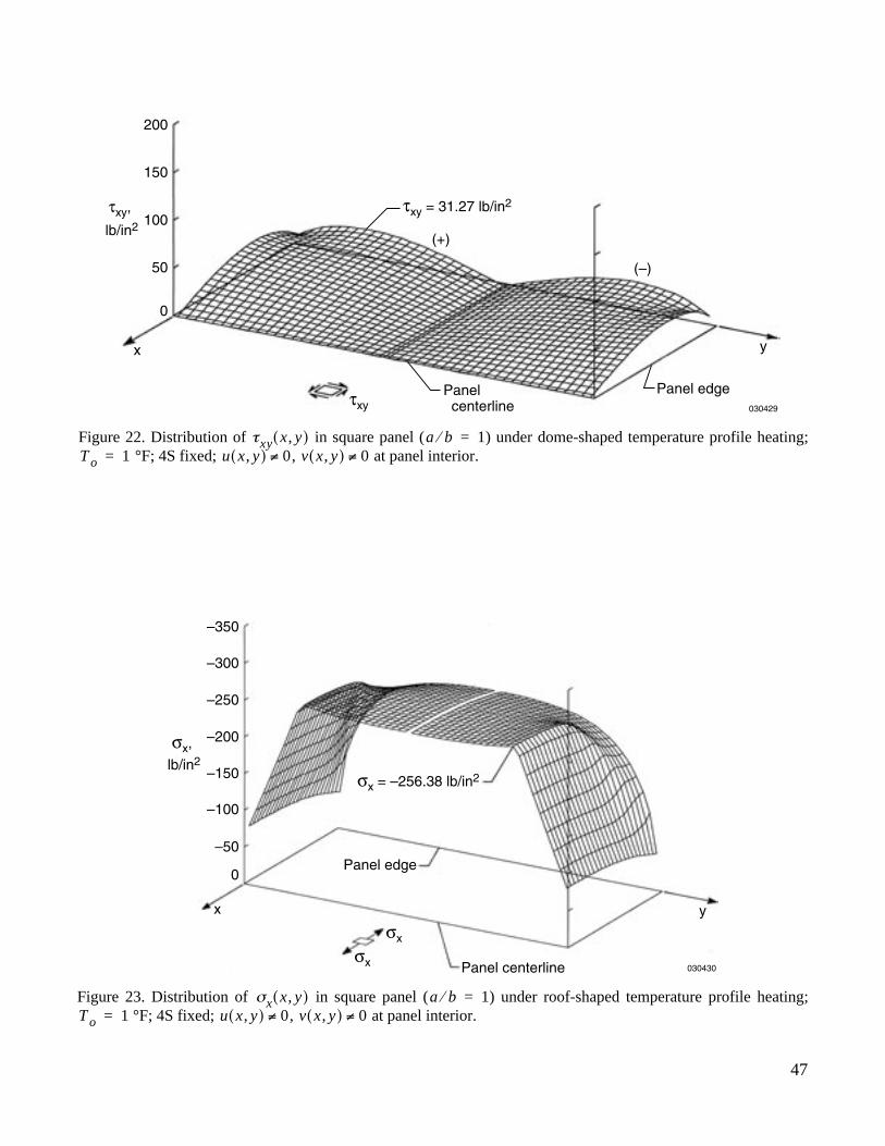
47
030429
200
τxy = 31.27 lb/in2τxy,
lb/in2
τxyPanel edge
y
(–)
(+)
x
Panelcenterline
150
100
50
0
Figure 22. Distribution of in square panel ( ) under dome-shaped temperature profile heating; °F; 4S fixed; , at panel interior.
τxy x y,( ) a b⁄ 1=T o 1= u x y,( ) 0≠ v x y,( ) 0≠
030430
–300
–350
σx
σx = –256.38 lb/in2
σx,
lb/in2
σx
Panel edge
yx
Panel centerline
–250
–200
–150
–100
–50
0
Figure 23. Distribution of in square panel ( ) under roof-shaped temperature profile heating; °F; 4S fixed; , at panel interior.
σx x y,( ) a b⁄ 1=T o 1= u x y,( ) 0≠ v x y,( ) 0≠
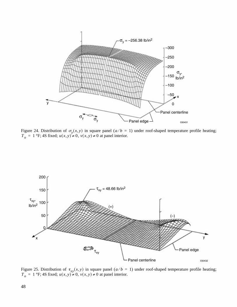
48
030431
–300
σy
σy = –256.38 lb/in2
σy,
lb/in2
σyPanel edge
y
x
Panel centerline
–250
–200
–150
–100
–50
0
Figure 24. Distribution of in square panel ( ) under roof-shaped temperature profile heating; °F; 4S fixed; , at panel interior.
σy x y,( ) a b⁄ 1=T o 1= u x y,( ) 0≠ v x y,( ) 0≠
030432
200
τxy = 48.66 lb/in2
τxy,
lb/in2
τxyPanel edge
y
(–)
(+)
x
Panel centerline
150
100
50
0
Figure 25. Distribution of in square panel ( ) under roof-shaped temperature profile heating; °F; 4S fixed; , at panel interior.
τxy x y,( ) a b⁄ 1=T o 1= u x y,( ) 0≠ v x y,( ) 0≠
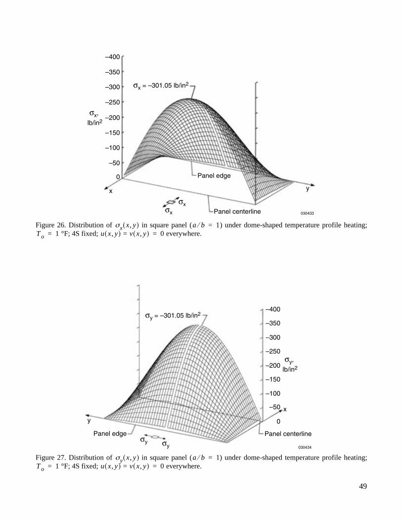
49
030433
–300
σx
σx = –301.05 lb/in2
σx,
lb/in2
σx
Panel edge
yx
Panel centerline
–250
–400
–350
–200
–150
–100
–50
0
Figure 26. Distribution of in square panel ( ) under dome-shaped temperature profile heating; °F; 4S fixed; everywhere.
σx x y,( ) a b⁄ 1=T o 1= u x y,( ) v= x y,( ) 0=
030434
–300
σy
σy = –301.05 lb/in2
σy,
lb/in2
σy
Panel edge
y
x
Panel centerline
–250
–400
–350
–200
–150
–100
–50
0
Figure 27. Distribution of in square panel ( ) under dome-shaped temperature profile heating; °F; 4S fixed; everywhere.
σy x y,( ) a b⁄ 1=T o 1= u x y,( ) v= x y,( ) 0=
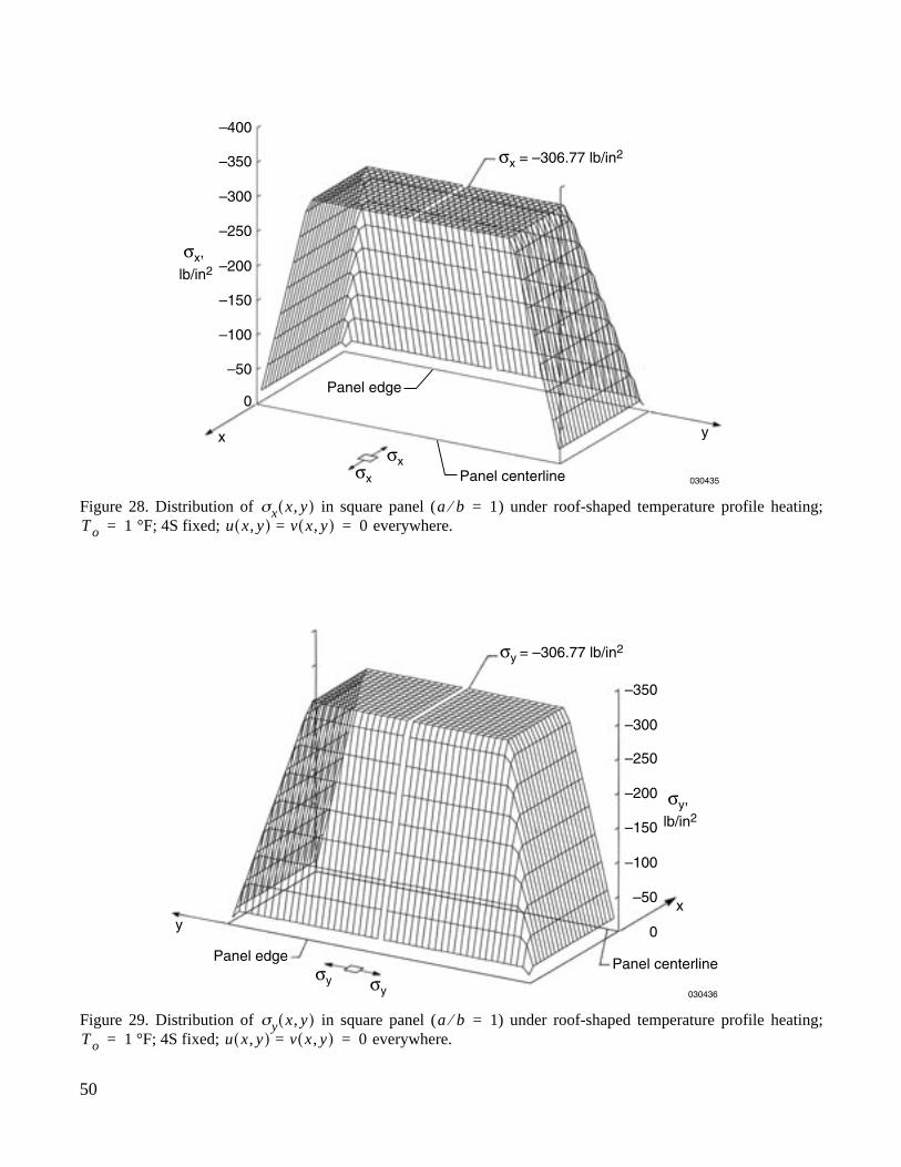
50
030435
–300
–350
–400
σx
σx = –306.77 lb/in2
σx,
lb/in2
σx
Panel edge
yx
Panel centerline
–250
–200
–150
–100
–50
0
Figure 28. Distribution of in square panel ( ) under roof-shaped temperature profile heating; °F; 4S fixed; everywhere.
σx x y,( ) a b⁄ 1=T o 1= u x y,( ) v= x y,( ) 0=
030436
–300
–350
σy
σy = –306.77 lb/in2
σy,
lb/in2
σy
Panel edge
yx
Panel centerline
–250
–200
–150
–100
–50
0
Figure 29. Distribution of in square panel ( ) under roof-shaped temperature profile heating; °F; 4S fixed; everywhere.
σy x y,( ) a b⁄ 1=T o 1= u x y,( ) v= x y,( ) 0=

REPORT DOCUMENTATION PAGE
Form ApprovedOMB No. 0704-0188
Public reporting burden for this collection of information is estimated to average 1 hour per response, including the time for reviewing instructions, searching existing data sources, gathering andmaintaining the data needed, and completing and reviewing the collection of information. Send comments regarding this burden estimate or any other aspect of this collection of information,including suggestions for reducing this burden, to Washington Headquarters Services, Directorate for Information Operations and Reports, 1215 Jefferson Davis Highway, Suite 1204, Arlington,VA 22202-4302, and to the Office of Management and Budget, Paperwork Reduction Project (0704-0188), Washington, DC 20503.
1. AGENCY USE ONLY (Leave blank) 2. REPORT DATE 3. REPORT TYPE AND DATES COVERED
4. TITLE AND SUBTITLE 5. FUNDING NUMBERS
6. AUTHOR(S)
8. PERFORMING ORGANIZATION REPORT NUMBER
7. PERFORMING ORGANIZATION NAME(S) AND ADDRESS(ES)
9. SPONSORING/MONITORING AGENCY NAME(S) AND ADDRESS(ES) 10. SPONSORING/MONITORING AGENCY REPORT NUMBER
11. SUPPLEMENTARY NOTES
12a. DISTRIBUTION/AVAILABILITY STATEMENT 12b. DISTRIBUTION CODE
13. ABSTRACT (Maximum 200 words)
14. SUBJECT TERMS 15. NUMBER OF PAGES
16. PRICE CODE
17. SECURITY CLASSIFICATION OF REPORT
18. SECURITY CLASSIFICATION OF THIS PAGE
19. SECURITY CLASSIFICATION OF ABSTRACT
20. LIMITATION OF ABSTRACT
NSN 7540-01-280-5500 Standard Form 298 (Rev. 2-89)
Prescribed by ANSI Std. Z39-18298-102
Thermal Buckling Analysis of Rectangular Panels Subjected to HumpedTemperature Profile Heating
WU 090-50-00-SE-RR-00-000
William L. Ko
NASA Dryden Flight Research CenterP.O. Box 273Edwards, California 93523-0273
H-2539
National Aeronautics and Space AdministrationWashington, DC 20546-0001 NASA/TP-2004-212041
This research investigates thermal buckling characteristics of rectangular panels subjected to differenttypes of humped temperature profile heating. Minimum potential energy and finite-element methods are usedto calculate the panel buckling temperatures. The two methods give fairly close thermal buckling solutions.“Buckling temperature magnification factor of the first kind,
η
” is established for the fixed panel edges to scaleup the buckling solution of uniform temperature loading case to give the buckling solution of the humpedtemperature profile loading cases. Also, “buckling temperature magnification factor of the second kind,
ξ
” isestablished for the free panel edges to scale up the buckling solution of humped temperature profile loadingcases with unheated boundary heat sinks to give the buckling solutions when the boundary heat sinks areheated up.
Buckling temperature magnification factors, Finite-element method, Humpedtemperature profile heating, Minimum potential energy method, Thermal buckling
A03
56
Unclassified Unclassified Unclassified Unlimited
January 2004 Technical Publication
Unclassified—UnlimitedSubject Category 39
This report is available at http://www.dfrc.nasa.gov/DTRS/


![Modeling and Buckling Analysis of Rectangular Plates in ANSYSijeas.akdeniz.edu.tr/wp-content/uploads/2019/05/310-329.pdf · For buckling analysis, Swamy [9] presented buckling of](https://img.pdfslide.us/doc/110x75/5fa5d3b4836cc632da4cc815/modeling-and-buckling-analysis-of-rectangular-plates-in-for-buckling-analysis-swamy.jpg)