Embed Size (px)
Citation preview
1912
Abstract Perforated steel thin plates are commonly used in structural engi-neering. Due to their geometric characteristics, these panels can suffer the undesired buckling phenomenon. In this context, the present work associates the computational modeling and the con-structal design method to evaluate the influence of the geometric configuration in the plate buckling behavior, using the exhaustive search method to determine which geometries conduct to superior mechanical behavior. To do so, numerical models are employed to solve elastic and elasto-plastic buckling of plates having a centered perforation. Different hole types (longitudinal oblong, transversal oblong, elliptical, rectangular, diamond, longitudinal hexagonal, or transversal hexagonal) with different shapes (variation of charac-teristics dimensions of each hole type) are analyzed. Limit curves to avoid buckling were obtained, as well as the definition of the geometries that can improve up to 107% the plate performance. Keywords Perforated steel thin plates, buckling, elastic, elasto-plastic, nu-merical simulation, constructal design, geometric optimization.
Study About Buckling Phenomenon in Perforated Thin Steel Plates Employing Computational Modeling and Constructal Design Method
Daniel Helbig a
Caio Cesar Cardoso da Silva b
Mauro de Vasconcellos Real c Elizaldo Domingues dos Santos d Liércio André Isoldi e Luiz Alberto Oliveira Rocha f
a Universidade Federal do Rio Grande do Sul (UFRGS) - Programa de Pós-Graduação em Engenharia Mecânica (PROMEC). [email protected] b Universidade Federal do Rio Grande (FURG) - Programa de Pós-Graduação em Engenharia Oceânica (PPGEO). [email protected] c FURG - PPGEO. [email protected] d FURG - PPGEO. [email protected] e FURG - PPGEO. [email protected] f UFRGS - PROMEC. [email protected] http://dx.doi.org/10.1590/1679-78252893 Received 29.02.2016 In revised form 02.05.2016 Accepted 02.05.2016 Available online 06.05.2016
D. Helbig et al. / Study About Buckling Phenomenon in Perforated Thin Steel Plates Employing Computational Modeling… 1913
Latin American Journal of Solids and Structures 13 (2016) 1912-1936
1 INTRODUCTION
Plates are slender structural components widely used in several engineering applications. They are straight and plane, having a geometric configuration where one dimension, referred to as thickness (t), is much smaller than the in-plane dimensions (Szilard, 2004). A plate can be considered as thin if its transverse shear deformations are negligible compared to its bending deflections (Gambhir, 2004).
The internal forces and deformations of slender members are determined by means of equilibri-um equations and compatibility conditions, allowing to analyze the mechanical behavior of these components. In some simple situations, the structural safety is verified by confirming that the max-imum stresses generated in the component are lower than the allowable stress of the material of which it is fabricated. This is a necessary but not sufficient condition if the structural member can suffer the buckling phenomenon (Silva, 2006).
Plate buckling is an instability phenomenon that happens when a compressive load generates a critical stress level that causes a very sudden deflection in the out-of-plane transverse direction. This compressive load can be produced by pure axial compression, but it can also be generated by bend-ing moment, shear or local concentrated loads, or by a combination among these (Åkesson, 2007). The plate buckling involves bending in two planes. As the plate midsurface is situated in the x0y plane, from a mathematical viewpoint, quantities such as deflections and bending moments become functions of two independent variables: x and y. Hence, the behavior of plates is governed by partial differential equations, which increases the complexity of analysis (Yoo and Lee, 2011).
In a general way, the plate buckling behavior can be classified in two categories: elastic buckling and elasto-plastic (or inelastic) buckling; which are defined by the critical stress level and by the ultimate stress level, respectively (Cheng and Zhao, 2010).
Therefore, the elastic buckling do not represents the collapse of the plate. After the elastic buck-ling occurrence the plate is usually able to resist additional load, with no fail, until it reaches a stress level considerably higher than its critical stress, called ultimate stress of the plate, causing the material yielding and hence the structural collapse (Iyengar, 1988). Accordingly, plates are charac-terized by buckling (elastic) and postbuckling (elasto-plastic) behaviors. So, the relative magnitude of the postbuckling strength (ultimate stress) to the critical buckling stress for a plate component depends on various parameters such as dimensional characteristics, boundary conditions, types of loading, and the ratio of buckling stress to yield stress (Yoo and Lee, 2011). It is important to em-phasize that in some cases the ultimate stress of the plate can be reached before the critical stress level, which defines the directly occurrence of the inelastic buckling (Ziemian, 2010), i.e., the mate-rial collapse can occur before any considerable buckling takes place (El-Sawy et al., 2004).
Besides, it is well known that in many practical situations it is necessary the existence of a cut-out in the plate component, for the purposes of access, services, weight reduction and even aesthet-ics. Obviously, the presence of this perforation affects the mechanical behavior of the plate, due to the redistribution of its membrane stresses. Previous works indicate that in a perforated plate there is a reduction in the ultimate stress if compared with a plate without perforations; but, surprisingly, in some cases an increase in the magnitude of the elastic critical stress can be observed when a per-forated plate is compared with a non-perforated plate (Cheng and Zhao, 2010).
1914 D. Helbig et al. / Study About Buckling Phenomenon in Perforated Thin Steel Plates Employing Computational Modeling…
Latin American Journal of Solids and Structures 13 (2016) 1912-1936
In this context, there are several studies focused in analyzing the buckling behavior of plates with openings. In the elastic buckling category, El-Sawy and Nazmy (2001) investigated the effect of aspect ratio on the elastic buckling critical loads of uniaxially loaded rectangular plates with ec-centric circular and rectangular (with curved corners) holes. El-Sawy and Martini (2007) used the finite element method to determine the elastic buckling stresses of biaxially loaded perforated rec-tangular plates with longitudinal axis located circular holes. Alternatively, Moen and Schafer (2009) developed, validated and summarized analytical expressions for estimating the influence of single or multiple holes on the elastic buckling critical stress of plates in bending or compression. In Rocha et al. (2012), Isoldi et al. (2013) and Rocha et al. (2013a) the constructal design method was employed to determine the best shape and size of centered cutout in a plate, aiming to maximize the critical buckling load. Regarding the researches dedicated to the elasto-plastic buckling, El-Sawy et al. (2004) investigated the elasto-plastic buckling of uniaxially loaded square and rectangular plates with circular cutouts by the use of the finite element method, including some recommendations about hole size and location for perforated plates of different aspect ratios and slenderness ratios. Afterwards, Paik (2007a), Paik (2007b) and Paik (2008) studied the ultimate strength characteris-tics of perforated plates under edge shear loading, axial compressive loading, combined biaxial com-pression and edge shear loads. Moreover, Paik proposed closed-form empirical formulae for predict-ing the ultimate strength of perforated plates based on the regression analysis of the nonlinear finite element analyses results. Maiorana et al. (2008) and Maiorana et al. (2009) focused on the linear and nonlinear finite element analyses of perforated plates subjected to localized symmetrical load. More recently, in Helbig et al. (2014) and in Lorenzini et al. (2016a, 2016b) the elastic and elasto-plastic buckling of perforated plates were analyzed, applying the computational modeling allied to the constructal design method. These last authors investigated the influence of shape and type of centered cutouts in the plate buckling, defining a stress limit curve to avoid the buckling occurrence in each studied case.
Thus, giving sequence to Helbig et al. (2014) and Lorenzini et al. (2016a, 2016b), the main pur-pose of the present work is to investigate the influence of the size, shape and type of the opening in the elastic and elasto-plastic buckling behavior of a thin steel plate. To do so, computational models developed in the software ANSYS (which is based on the finite element method) were used to nu-merically predict the elastic critical stress and the elasto-plastic ultimate stress. Moreover, the con-structal design method was employed to define the cutout shape variations for different sizes and types of perforations, allowing a consistent comparison among them. Thereby, combining the elastic and the elasto-plastic behaviors it was possible to define limit stress curves that should not be ex-ceeded to avoid the buckling phenomenon on the studied plates. It is also important to mention that here are considered additional hole sizes and hole types from those used in Helbig et al. (2014) and Lorenzini et al. (2016a, 2016b). 2 BUCKLING AND POSTBUCKLING OF PLATES
Structural instability is defined as a condition wherein a compression member loses its ability to resist increasing loads, exhibiting instead a decrease in load-carrying capacity. The instability prob-lems can be subdivided into two categories: those related with the bifurcation of equilibrium, and those in which the instability occurs when the structural component achieves a maximum or ulti-
D. Helbig et al. / Study About Buckling Phenomenon in Perforated Thin Steel Plates Employing Computational Modeling… 1915
Latin American Journal of Solids and Structures 13 (2016) 1912-1936
mate stress without bifurcation. In the first case an ideal structural component subjected to increas-ing compression axial load will initially deform in one mode and then, at a specific load referred to as critical buckling load, its deformation suddenly changes to a different pattern. In turn, the struc-tural members belonging to the latter group suffer deformation in a single mode from the start of loading until reaching the ultimate load level (Galambos, 1998).
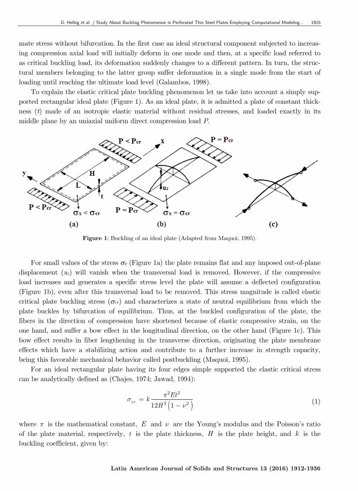
To explain the elastic critical plate buckling phenomenon let us take into account a simply sup-ported rectangular ideal plate (Figure 1). As an ideal plate, it is admitted a plate of constant thick-ness (t) made of an isotropic elastic material without residual stresses, and loaded exactly in its middle plane by an uniaxial uniform direct compression load P.
Figure 1: Buckling of an ideal plate (Adapted from Maquoi, 1995).
For small values of the stress x (Figure 1a) the plate remains flat and any imposed out-of-plane
displacement (uz) will vanish when the transversal load is removed. However, if the compressive load increases and generates a specific stress level the plate will assume a deflected configuration (Figure 1b), even after this transversal load to be removed. This stress magnitude is called elastic critical plate buckling stress (cr) and characterizes a state of neutral equilibrium from which the plate buckles by bifurcation of equilibrium. Thus, at the buckled configuration of the plate, the fibers in the direction of compression have shortened because of elastic compressive strain, on the one hand, and suffer a bow effect in the longitudinal direction, on the other hand (Figure 1c). This bow effect results in fiber lengthening in the transverse direction, originating the plate membrane effects which have a stabilizing action and contribute to a further increase in strength capacity, being this favorable mechanical behavior called postbuckling (Maquoi, 1995).
For an ideal rectangular plate having its four edges simple supported the elastic critical stress can be analytically defined as (Chajes, 1974; Jawad, 1994):
( )2 2
2 212 1cr
EtkH
ps
n=
- (1)
where p is the mathematical constant, E and n are the Young’s modulus and the Poisson’s ratio of the plate material, respectively, t is the plate thickness, H is the plate height, and k is the buckling coefficient, given by:
1916 D. Helbig et al. / Study About Buckling Phenomenon in Perforated Thin Steel Plates Employing Computational Modeling…
Latin American Journal of Solids and Structures 13 (2016) 1912-1936
21H L
k mL m H
æ ö÷ç= + ÷ç ÷ç ÷è ø (2)
being L the plate length and m the number of half waves that occur in the plate’s longitudinal direction at buckling, defining the buckling mode of the plate.
As it was explained, the theoretical critical buckling stress of an initially perfect plate supported along its edges is obtained from the concept of bifurcation of equilibrium. However, in practice the response of structures is continuous, due to the inevitable presence of initial imperfections. Thus the critical stress must be viewed as a useful index to the behavior, and plates can continue to carry additional loads well after initial buckling. Postbuckling resistance in plates is due to the redistribu-tion of axial compressive stresses and, to a lesser extent, to the membrane tensions that accompany the out-of-plane bending of the plate in both the longitudinal and transverse directions. The longi-tudinal stresses tend to concentrate in the vicinity of the longitudinally supported edges, which are the stiffest parts of the buckled plate. As a result, yielding begins along these edges, which limits the load-carrying capacity (Galambos, 1998). Therefore, the plate components can, subsequent to reaching the critical stress, continue to resist increasing axial force, and they do not fail until a stress considerably higher than the critical stress is reached. The critical stress of a plate is therefore not its failure limit. Instead, the ultimate stress (u) of a plate must be determined by considering its postbuckling behavior (Chajes, 1974).
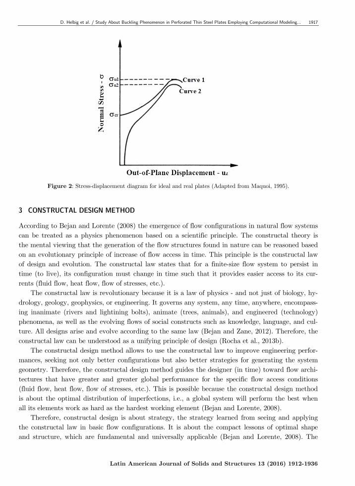
To understand these mechanical behaviors, Figure 2 shows a stress-displacement diagram where curves 1 and 2 represent the response of an ideal plate and a real plate, respectively. One can ob-serve in curve 1 that until the critical stress is reached there is no out-of-plane displacement on the plate. From this level of stress, the buckling occurs and the out-of-plane displacements will increase until the ultimate stress of the plate is achieved. In turn, curve 2 illustrates that due to the inherent imperfections of a real plate its out-of-plane displacements grow up as soon as the initial load is applied. As the load increases the out-of-plane strains are also augmented until the occurrence of the plate collapse at the ultimate stress by material yielding. Therefore, a real plate buckles by di-vergence of equilibrium and exhibits nonlinear behaviors of prebluckling and postbuckling (Maquoi, 1995).
It is clear that the elastic critical buckling stresses do not directly indicate the actual behavior that may occur in plates; material and geometric effects often complicate the response. It is frequent to adopt the elastic critical buckling stress as a reference for defining different forms of plate buck-ling behavior. If the material yielding occurs prior to the elastic critical buckling stress, this is known as inelastic buckling. The plate behavior at stress magnitudes greater than the elastic critical buckling stress, and the associated deformations that occur under such loading, are referred to as postbuckling and may be either elastic or inelastic. Finally, the ultimate stress refers to the maxi-mum load that the plate may carry, typically independent of deformation, which may be quite large (Ziemian, 2010).
As it was earlier mentioned, several aspects may influence the buckling pattern which will occur on a plate. Therefore, if the plate has a cutout, its buckling behavior certainly will be directly af-fected depending of the type, shape, size and location of the perforation, justifying the study pro-posed at the present work.
D. Helbig et al. / Study About Buckling Phenomenon in Perforated Thin Steel Plates Employing Computational Modeling… 1917
Latin American Journal of Solids and Structures 13 (2016) 1912-1936
Figure 2: Stress-displacement diagram for ideal and real plates (Adapted from Maquoi, 1995).
3 CONSTRUCTAL DESIGN METHOD
According to Bejan and Lorente (2008) the emergence of flow configurations in natural flow systems can be treated as a physics phenomenon based on a scientific principle. The constructal theory is the mental viewing that the generation of the flow structures found in nature can be reasoned based on an evolutionary principle of increase of flow access in time. This principle is the constructal law of design and evolution. The constructal law states that for a finite-size flow system to persist in time (to live), its configuration must change in time such that it provides easier access to its cur-rents (fluid flow, heat flow, flow of stresses, etc.).
The constructal law is revolutionary because it is a law of physics - and not just of biology, hy-drology, geology, geophysics, or engineering. It governs any system, any time, anywhere, encompass-ing inanimate (rivers and lightining bolts), animate (trees, animals), and engineered (technology) phenomena, as well as the evolving flows of social constructs such as knowledge, language, and cul-ture. All designs arise and evolve according to the same law (Bejan and Zane, 2012). Therefore, the constructal law can be understood as a unifying principle of design (Rocha et al., 2013b).
The constructal design method allows to use the constructal law to improve engineering perfor-mances, seeking not only better configurations but also better strategies for generating the system geometry. Therefore, the constructal design method guides the designer (in time) toward flow archi-tectures that have greater and greater global performance for the specific flow access conditions (fluid flow, heat flow, flow of stresses, etc.). This is possible because the constructal design method is about the optimal distribution of imperfections, i.e., a global system will perform the best when all its elements work as hard as the hardest working element (Bejan and Lorente, 2008).
Therefore, constructal design is about strategy, the strategy learned from seeing and applying the constructal law in basic flow configurations. It is about the compact lessons of optimal shape and structure, which are fundamental and universally applicable (Bejan and Lorente, 2008). The
1918 D. Helbig et al. / Study About Buckling Phenomenon in Perforated Thin Steel Plates Employing Computational Modeling…
Latin American Journal of Solids and Structures 13 (2016) 1912-1936
constructal design method has been employed for several applications in all the domains of design generation and evolution, from biology and physics to social organization, technology evolution, sustainability and engineering (Bejan and Lorente, 2008; Bejan and Zane, 2012). Among engineering applications, the vast majority are related to the development of architectures on the fluid mechan-ics (e.g. Bejan, 2000; Bejan and Lorente, 2004; Reis, 2006; Bejan and Lorente, 2008; and Cetkin et al., 2010) and heat transfer (e.g. Bejan and Almogbel, 2000; Biserni et al., 2007; Xie et al., 2010; Lorenzini et al., 2014a; Lorenzini et al., 2014b; and Rodrigues et al., 2015) areas.
The key proposal here is to view the mechanic of materials in the same way that flow configura-tions are treated in fluid mechanics or heat transfer: mechanical structures are networks through which stresses flow from components to their neighbors (Bejan and Lorente, 2008). The approach considering the stresses as flow is not so usual but it is effective if the objective is to discover the best geometric configuration of the mechanical structure (Lorente et al., 2010). Currently only few works employing the constructal design method in structural analysis can be found in literature, however the results presented in these publications show the effectiveness and applicability of the constructal design also in the solid mechanics area. The main works where the constructal design method is applied in the mechanic of materials problems are: Lorente and Bejan (2002), Lorente et al. (2010), Rocha et al. (2012), Rocha et al. (2013a), Helbig et al. (2014), and Lorenzini et al. (2016a, 2016b).
It is well known in structural engineering that concentrations of maximum stresses are not good for performance. The best use of a mechanical resistant material is achieved when the maximum allowable stresses are distributed uniformly through the available material. This design principle is taken for granted, as something that is intuitively obvious. However, it follows from the constructal law where it is named Principle of the Optimal Distribution of Imperfections (Bejan and Lorente, 2008). The use of constructal design method provides the achievement of this goal, i.e., the optimal distribution of the maximum allowable stresses. 3.1 Constructal Design Application
Here, it is important to emphasize that the application of the constructal design method allows to evaluate the influence of the geometric configuration on the performance of a physical system. If all possible geometric configurations proposed with the constructal design are evaluated, one can say that a geometric optimization procedure is performed by means the exhaustive search method.
Therefore, in order to apply the constructal design method, it is, basically, necessary the defini-tion of: objective functions, degrees of freedom, and constraints. From this, the several possible ge-ometries are generated, enabling the employment of the exhaustive search method. However, it can be used another optimization method if the degrees of freedom and/or parameters are too many, as can be seen in Lorenzini et al. (2014b) and Gonzales et al. (2015).
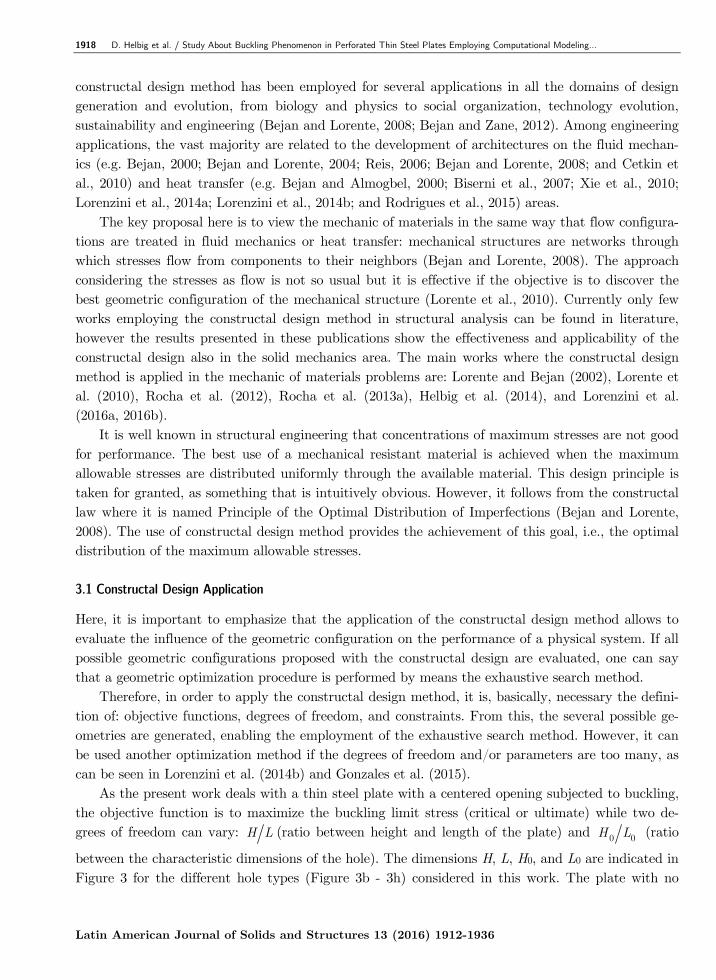
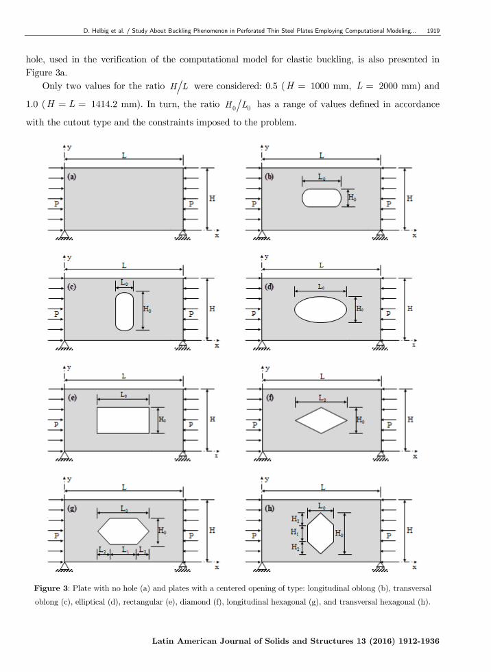
As the present work deals with a thin steel plate with a centered opening subjected to buckling, the objective function is to maximize the buckling limit stress (critical or ultimate) while two de-grees of freedom can vary: H L (ratio between height and length of the plate) and 0 0H L (ratio
between the characteristic dimensions of the hole). The dimensions H, L, H0, and L0 are indicated in Figure 3 for the different hole types (Figure 3b - 3h) considered in this work. The plate with no
D. Helbig et al. / Study About Buckling Phenomenon in Perforated Thin Steel Plates Employing Computational Modeling… 1919
Latin American Journal of Solids and Structures 13 (2016) 1912-1936
hole, used in the verification of the computational model for elastic buckling, is also presented in Figure 3a.
Only two values for the ratio H L were considered: 0.5 (H = 1000 mm, L = 2000 mm) and
1.0 (H L= = 1414.2 mm). In turn, the ratio 0 0H L has a range of values defined in accordance
with the cutout type and the constraints imposed to the problem.
Figure 3: Plate with no hole (a) and plates with a centered opening of type: longitudinal oblong (b), transversal
oblong (c), elliptical (d), rectangular (e), diamond (f), longitudinal hexagonal (g), and transversal hexagonal (h).
1920 D. Helbig et al. / Study About Buckling Phenomenon in Perforated Thin Steel Plates Employing Computational Modeling…
Latin American Journal of Solids and Structures 13 (2016) 1912-1936
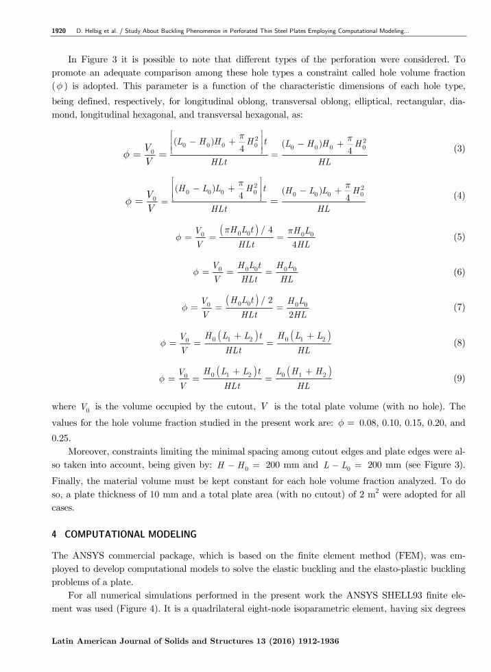
In Figure 3 it is possible to note that different types of the perforation were considered. To promote an adequate comparison among these hole types a constraint called hole volume fraction (f ) is adopted. This parameter is a function of the characteristic dimensions of each hole type,
being defined, respectively, for longitudinal oblong, transversal oblong, elliptical, rectangular, dia-mond, longitudinal hexagonal, and transversal hexagonal, as:
2 20 0 0 0 0 0 0 0
0
( ) ( )4 4
L H H H t L H H H
HLt HL
VV
p p
f
é ùê ú- + - +ê úë û == = (3)
2 20 0 0 0 0 0 0 0
0
( ) ( )4 4
H L L H t H L L H
HLt HL
VV
p p
f
é ùê ú- + - +ê úë û== = (4)
( )0 00 0 0/ 4
4
H L tV H L
V HLt HL
p pf = = = (5)
0 0 0 0 0V H L t H L
V HLt HLf = = = (6)
( )0 00 0 0/ 2
2
H L tV H L
V HLt HLf = = = (7)
( ) ( )0 1 2 0 1 20H L L t H L LV
V HLt HLf
+ += = = (8)
( ) ( )0 1 2 0 1 20H L L t L H HV
V HLt HLf
+ += = = (9)
where 0V is the volume occupied by the cutout, V is the total plate volume (with no hole). The
values for the hole volume fraction studied in the present work are: f = 0.08, 0.10, 0.15, 0.20, and
0.25. Moreover, constraints limiting the minimal spacing among cutout edges and plate edges were al-
so taken into account, being given by: 0H H- = 200 mm and 0L L- = 200 mm (see Figure 3).
Finally, the material volume must be kept constant for each hole volume fraction analyzed. To do so, a plate thickness of 10 mm and a total plate area (with no cutout) of 2 m2 were adopted for all cases. 4 COMPUTATIONAL MODELING
The ANSYS commercial package, which is based on the finite element method (FEM), was em-ployed to develop computational models to solve the elastic buckling and the elasto-plastic buckling problems of a plate.
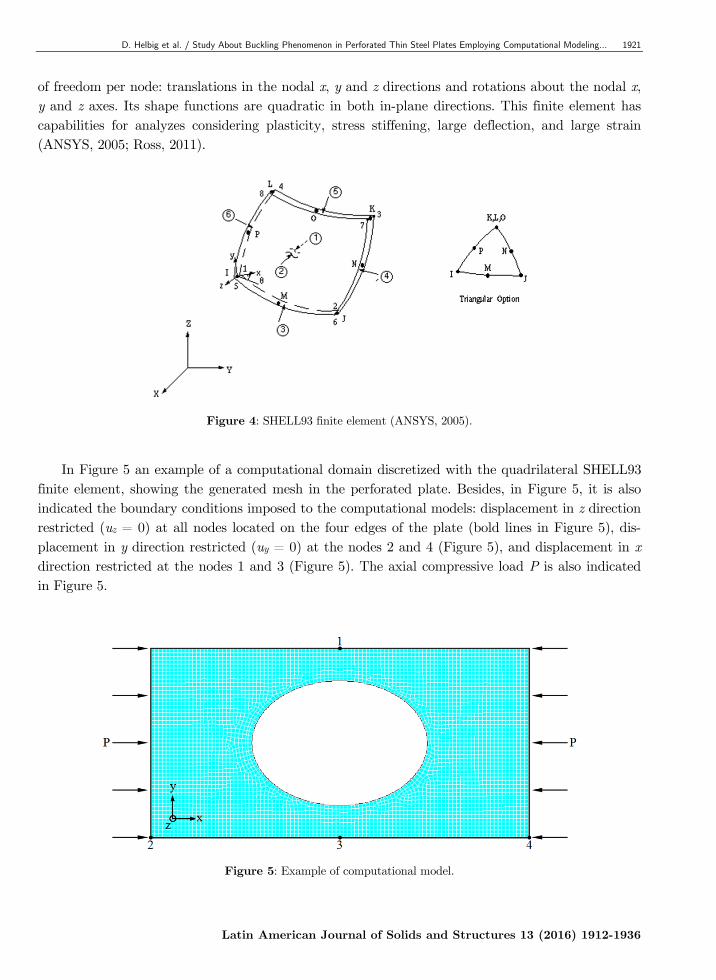
For all numerical simulations performed in the present work the ANSYS SHELL93 finite ele-ment was used (Figure 4). It is a quadrilateral eight-node isoparametric element, having six degrees
D. Helbig et al. / Study About Buckling Phenomenon in Perforated Thin Steel Plates Employing Computational Modeling… 1921
Latin American Journal of Solids and Structures 13 (2016) 1912-1936
of freedom per node: translations in the nodal x, y and z directions and rotations about the nodal x, y and z axes. Its shape functions are quadratic in both in-plane directions. This finite element has capabilities for analyzes considering plasticity, stress stiffening, large deflection, and large strain (ANSYS, 2005; Ross, 2011).
Figure 4: SHELL93 finite element (ANSYS, 2005).
In Figure 5 an example of a computational domain discretized with the quadrilateral SHELL93
finite element, showing the generated mesh in the perforated plate. Besides, in Figure 5, it is also indicated the boundary conditions imposed to the computational models: displacement in z direction restricted (uz = 0) at all nodes located on the four edges of the plate (bold lines in Figure 5), dis-placement in y direction restricted (uy = 0) at the nodes 2 and 4 (Figure 5), and displacement in x direction restricted at the nodes 1 and 3 (Figure 5). The axial compressive load P is also indicated in Figure 5.
Figure 5: Example of computational model.
1922 D. Helbig et al. / Study About Buckling Phenomenon in Perforated Thin Steel Plates Employing Computational Modeling…
Latin American Journal of Solids and Structures 13 (2016) 1912-1936
4.1 Linear Elastic Buckling
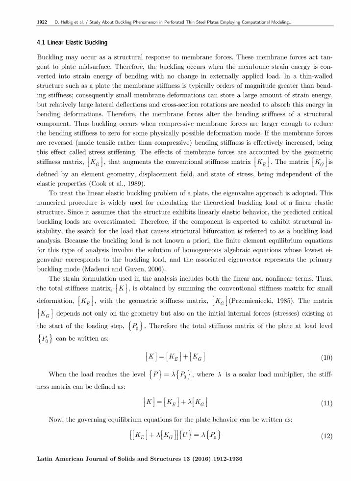
Buckling may occur as a structural response to membrane forces. These membrane forces act tan-gent to plate midsurface. Therefore, the buckling occurs when the membrane strain energy is con-verted into strain energy of bending with no change in externally applied load. In a thin-walled structure such as a plate the membrane stiffness is typically orders of magnitude greater than bend-ing stiffness; consequently small membrane deformations can store a large amount of strain energy, but relatively large lateral deflections and cross-section rotations are needed to absorb this energy in bending deformations. Therefore, the membrane forces alter the bending stiffness of a structural component. Thus buckling occurs when compressive membrane forces are larger enough to reduce the bending stiffness to zero for some physically possible deformation mode. If the membrane forces are reversed (made tensile rather than compressive) bending stiffness is effectively increased, being this effect called stress stiffening. The effects of membrane forces are accounted by the geometric stiffness matrix, GKé ùë û , that augments the conventional stiffness matrix EKé ùë û . The matrix GKé ùë û is
defined by an element geometry, displacement field, and state of stress, being independent of the elastic properties (Cook et al., 1989).
To treat the linear elastic buckling problem of a plate, the eigenvalue approach is adopted. This numerical procedure is widely used for calculating the theoretical buckling load of a linear elastic structure. Since it assumes that the structure exhibits linearly elastic behavior, the predicted critical buckling loads are overestimated. Therefore, if the component is expected to exhibit structural in-stability, the search for the load that causes structural bifurcation is referred to as a buckling load analysis. Because the buckling load is not known a priori, the finite element equilibrium equations for this type of analysis involve the solution of homogeneous algebraic equations whose lowest ei-genvalue corresponds to the buckling load, and the associated eigenvector represents the primary buckling mode (Madenci and Guven, 2006).
The strain formulation used in the analysis includes both the linear and nonlinear terms. Thus, the total stiffness matrix, Ké ùë û , is obtained by summing the conventional stiffness matrix for small
deformation, EKé ùë û , with the geometric stiffness matrix, GKé ùë û (Przemieniecki, 1985). The matrix
GKé ùë û depends not only on the geometry but also on the initial internal forces (stresses) existing at
the start of the loading step, { }0P . Therefore the total stiffness matrix of the plate at load level
{ }0P can be written as:
E GK K Ké ù é ù é ù= +ë û ë û ë û (10)
When the load reaches the level { } { }0P Pl= , where l is a scalar load multiplier, the stiff-
ness matrix can be defined as:
E GK K Klé ù é ù é ù= +ë û ë û ë û (11)
Now, the governing equilibrium equations for the plate behavior can be written as:
{ } { }0E GK K U Pl lé é ù é ù ù+ =ë ë û ë û û (12)
D. Helbig et al. / Study About Buckling Phenomenon in Perforated Thin Steel Plates Employing Computational Modeling… 1923
Latin American Journal of Solids and Structures 13 (2016) 1912-1936
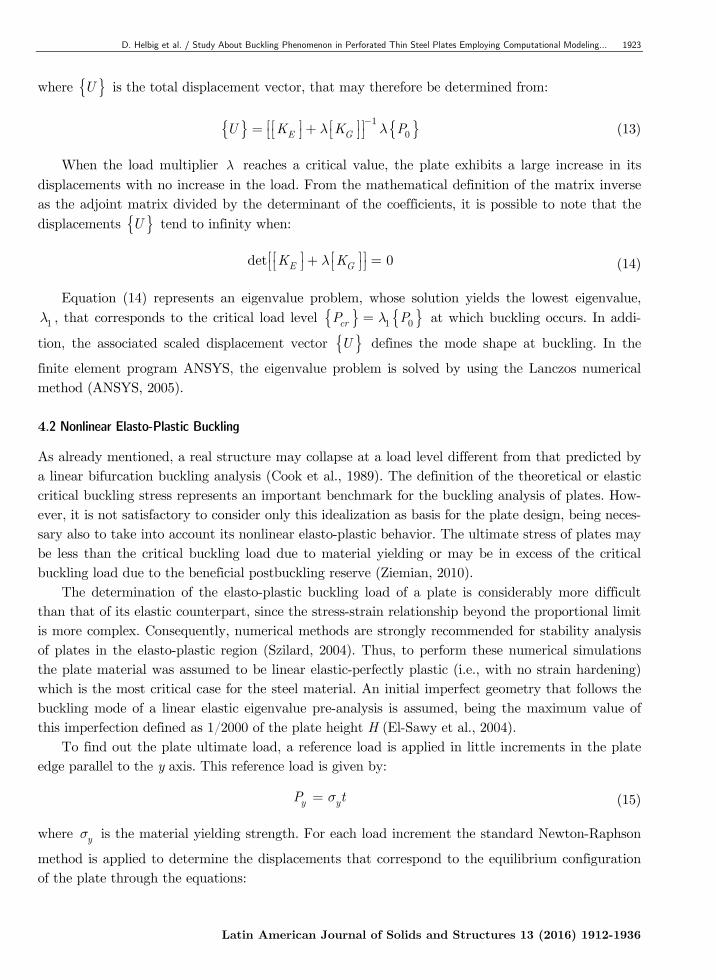
where { }U is the total displacement vector, that may therefore be determined from:
{ } { }1
0E GU K K Pl l-é é ù é ù ù= +ë ë û ë û û (13)
When the load multiplier l reaches a critical value, the plate exhibits a large increase in its displacements with no increase in the load. From the mathematical definition of the matrix inverse as the adjoint matrix divided by the determinant of the coefficients, it is possible to note that the displacements { }U tend to infinity when:
det 0E GK Klé é ù é ù ù+ =ë ë û ë û û (14)
Equation (14) represents an eigenvalue problem, whose solution yields the lowest eigenvalue,
1l , that corresponds to the critical load level { } { }1 0crP Pl= at which buckling occurs. In addi-
tion, the associated scaled displacement vector { }U defines the mode shape at buckling. In the
finite element program ANSYS, the eigenvalue problem is solved by using the Lanczos numerical method (ANSYS, 2005). 4.2 Nonlinear Elasto-Plastic Buckling
As already mentioned, a real structure may collapse at a load level different from that predicted by a linear bifurcation buckling analysis (Cook et al., 1989). The definition of the theoretical or elastic critical buckling stress represents an important benchmark for the buckling analysis of plates. How-ever, it is not satisfactory to consider only this idealization as basis for the plate design, being neces-sary also to take into account its nonlinear elasto-plastic behavior. The ultimate stress of plates may be less than the critical buckling load due to material yielding or may be in excess of the critical buckling load due to the beneficial postbuckling reserve (Ziemian, 2010).
The determination of the elasto-plastic buckling load of a plate is considerably more difficult than that of its elastic counterpart, since the stress-strain relationship beyond the proportional limit is more complex. Consequently, numerical methods are strongly recommended for stability analysis of plates in the elasto-plastic region (Szilard, 2004). Thus, to perform these numerical simulations the plate material was assumed to be linear elastic-perfectly plastic (i.e., with no strain hardening) which is the most critical case for the steel material. An initial imperfect geometry that follows the buckling mode of a linear elastic eigenvalue pre-analysis is assumed, being the maximum value of this imperfection defined as 1/2000 of the plate height H (El-Sawy et al., 2004).
To find out the plate ultimate load, a reference load is applied in little increments in the plate edge parallel to the y axis. This reference load is given by:
y yP ts= (15)
where ys is the material yielding strength. For each load increment the standard Newton-Raphson
method is applied to determine the displacements that correspond to the equilibrium configuration of the plate through the equations:
1924 D. Helbig et al. / Study About Buckling Phenomenon in Perforated Thin Steel Plates Employing Computational Modeling…
Latin American Journal of Solids and Structures 13 (2016) 1912-1936
{ } { } { }1i i
P P P+
= + D (16)
{ } { } { }1 NLi
P Fy+
= - (17)
{ } { }tK U yé ù D =ë û (18)
{ } { } { }1i i
U U U+
= + D (19)
where tKé ùë û is updated tangent stiffness matrix, { }UD is the displacement increment vector neces-
sary to reach the equilibrium configuration, { }NLF is the nonlinear internal forces vector and { }y
is the out-of-balance load vector. The vectors { }i
U and { }1i
U+
correspond to the displacements,
while the vectors { }i
P and { }1i
P+
correspond to the applied external loads at two successive
equilibrium configurations of the structure. If at a certain load stage the convergence could not be achieved, i.e., a finite displacement in-
crement cannot be determined so that the out-of-balance load vector { }y is annulled, this means
that the failure load of the structure has been reached. This occurs because no matter as large as the displacements and strains can be the stresses and internal forces cannot increase as it would be required to balance the external loads, indicating that the material has reached its ultimate strength.
In the nonlinear analyses of plates carried out in this paper the reference load was divided into 100 increments and a maximum of 200 iterations was established for each load step. The same spa-tial discretization used for the elastic linear buckling was adopted to perform the elasto-plastic non-linear buckling simulations. 5 RESULTS AND DISCUSSIONS
As initial results, the verification of the elastic buckling computational model and the validation of the elasto-plastic buckling computational model are presented. After that, thin steel plates with H L = 0.5 and H L = 1.0, both having a centered perforation which can assume different types
(longitudinal oblong, transversal oblong, elliptical, rectangular, diamond, longitudinal hexagonal, or transversal hexagonal), different sizes (f = 0.08, 0.10, 0.15, 0.20, or 0.25), and different shapes by
means the 0 0H L variation, are submitted to buckling.
5.1 Verification and Validation
To perform the verification of the elastic buckling computational model its result for the critical load of a steel plate without perforation (see Figure 3a) is compared with the analytic solution given by Equation (1). The four edges of the plate are simply supported and its mechanical properties and dimensions are: E = 210 GPa, n = 0.3, ys = 250 MPa, H = 1000 mm, L = 2000 mm and t =
10 mm. A structured and converged mesh with square finite elements of 20 mm side is generated,
D. Helbig et al. / Study About Buckling Phenomenon in Perforated Thin Steel Plates Employing Computational Modeling… 1925
Latin American Journal of Solids and Structures 13 (2016) 1912-1936
obtaining a critical stress of crs = 75.37 MPa. This value when compared with the analytical criti-
cal stress of crs = 75.92 MPa presents a difference of -0.72%, verifying the computational model
employed. In turn the computational model for the elasto-plastic buckling analysis is validated with the
experimental ultimate load presented in El-Sawy et al. (2004). To do so, it is used a four edge simp-ly supported steel plate with dimensions of H L= = 1000 mm and t = 20 mm; mechanical prop-erties of E = 210 GPa n = 0.3, ys = 350 MPa; and having a centered circular cutout of
0 0H L= = 300 mm. The computational domain is discretized by quadrilateral finite elements with
maximum size of 20 mm. The ultimate stress experimentally determined by El-Sawy et al. (2004) is
us = 213.50 MPa while the numerical result obtained in the present study is us = 217.00 MPa,
presenting a difference of 1.64% which validates the proposed computational model. 5.2 Case Study
As earlier commented, the goal here is to define a limit curve that avoid the buckling occurrence. For this, the critical stress (elastic buckling) and ultimate stress (elasto-plastic buckling) numerical-ly obtained are normalized, respectively, as follow:
crEB
y
NLSss
= (20)
uEPB
y
NLSss
= (21)
being NLS the normalized limit stress and the subscripts EB and EPB indicating, respectively, the elastic buckling and the elasto-plastic buckling.
It is worth to mention that for all numerical simulations of the case study steel plates with ma-terial properties E = 210 GPa, n = 0.3, and ys = 250 MPa, and with thickness of t = 10 mm,
are used. To explain how the limit curves are obtained the longitudinal and transversal oblong openings
are employed. These types of hole were chosen because they have a peculiar complementary behav-ior, which is not exhibited by any other type of hole studied in the present work. Thus, considering f =0.15 and varying the ratio 0 0H L it is possible to determine the NLS for the elastic and elasto-
plastic buckling, allowing to plot the curves presented in Figure 6. About the peculiar behavior of the oblong cutout it is possible to note in Figure 6 that only one
curve is formed from the elastic buckling (in blue color) and only one curve is formed from the elas-to-plastic buckling (in red color). Part of these curves (continuous line) is referent to the 0 0H L
variation for the longitudinal oblong ( 0 0H L < 1) and the remaining (dashed line) is concerned
with the 0 0H L variation of the transversal oblong ( 0 0H L > 1). In addition, when 0 0H L = 1
the geometric configuration of the oblong hole becomes a circular hole. For the other types of hole
1926 D. Helbig et al. / Study About Buckling Phenomenon in Perforated Thin Steel Plates Employing Computational Modeling…
Latin American Journal of Solids and Structures 13 (2016) 1912-1936
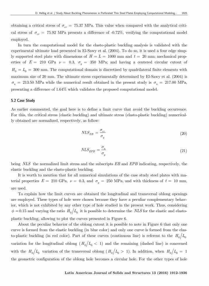
this complementary behavior does not exist, hence for these hole types a unique curve will be ob-tained.
Figure 6: Elastic and elasto-plastic buckling curves for the longitudinal oblong and transversal oblong
cutouts for f = 0.15: (a) H L = 0.5, and (b) H L = 1.0.
Moreover, in Figure 6 one can observe an intersection point between the elastic buckling curve
(in blue color) and the elasto-plastic buckling curve (in red color), marking the transition from the elastic buckling behavior to the elasto-plastic buckling behavior. This change in the buckling behav-ior happens due to the 0 0H L variation, i.e. depending of the hole shape an elastic or an elasto-
plastic buckling can occur. It is also noted that for 0 0H L values lower than the 0 0H L of the
intersection point the plate buckling is elastic and a post-buckling behavior is possible, while for
0 0H L values higher than the 0 0H L of the intersection point the elasto-plastic is directly achieved
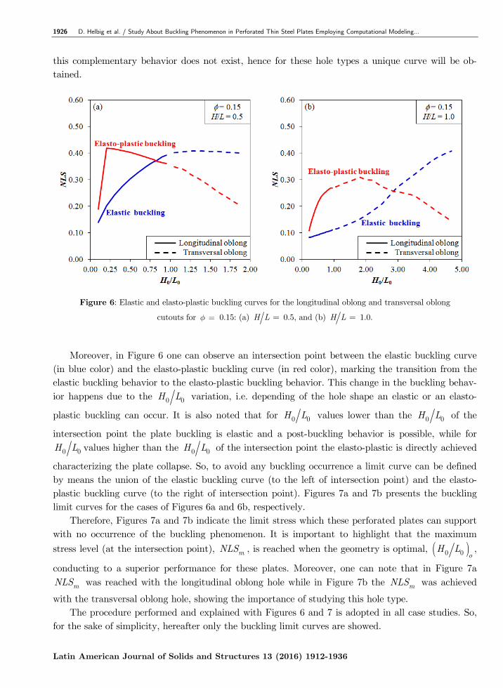
characterizing the plate collapse. So, to avoid any buckling occurrence a limit curve can be defined by means the union of the elastic buckling curve (to the left of intersection point) and the elasto-plastic buckling curve (to the right of intersection point). Figures 7a and 7b presents the buckling limit curves for the cases of Figures 6a and 6b, respectively.
Therefore, Figures 7a and 7b indicate the limit stress which these perforated plates can support with no occurrence of the buckling phenomenon. It is important to highlight that the maximum
stress level (at the intersection point), mNLS , is reached when the geometry is optimal, ( )0 0 oH L ,
conducting to a superior performance for these plates. Moreover, one can note that in Figure 7a
mNLS was reached with the longitudinal oblong hole while in Figure 7b the mNLS was achieved
with the transversal oblong hole, showing the importance of studying this hole type. The procedure performed and explained with Figures 6 and 7 is adopted in all case studies. So,
for the sake of simplicity, hereafter only the buckling limit curves are showed.
D. Helbig et al. / Study About Buckling Phenomenon in Perforated Thin Steel Plates Employing Computational Modeling… 1927
Latin American Journal of Solids and Structures 13 (2016) 1912-1936
Figure 7: Buckling limit curves for the longitudinal oblong and transversal oblong cutouts
for f = 0.15: (a) H L = 0.5, and (b) H L = 1.0.
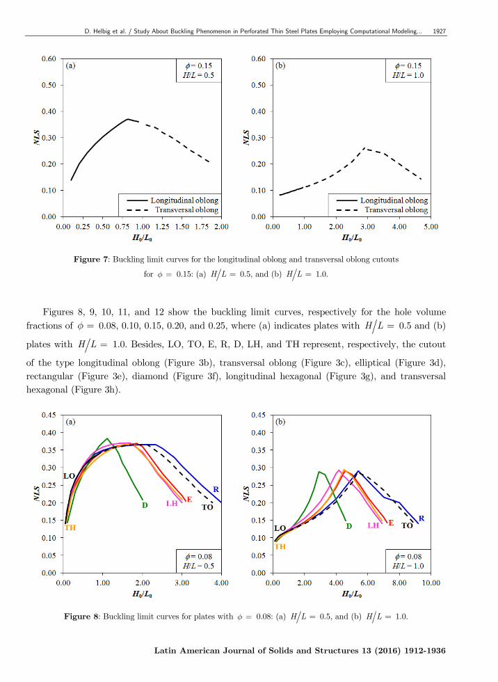
Figures 8, 9, 10, 11, and 12 show the buckling limit curves, respectively for the hole volume
fractions of f = 0.08, 0.10, 0.15, 0.20, and 0.25, where (a) indicates plates with H L = 0.5 and (b)
plates with H L = 1.0. Besides, LO, TO, E, R, D, LH, and TH represent, respectively, the cutout
of the type longitudinal oblong (Figure 3b), transversal oblong (Figure 3c), elliptical (Figure 3d), rectangular (Figure 3e), diamond (Figure 3f), longitudinal hexagonal (Figure 3g), and transversal hexagonal (Figure 3h).
Figure 8: Buckling limit curves for plates with f = 0.08: (a) H L = 0.5, and (b) H L = 1.0.
1928 D. Helbig et al. / Study About Buckling Phenomenon in Perforated Thin Steel Plates Employing Computational Modeling…
Latin American Journal of Solids and Structures 13 (2016) 1912-1936
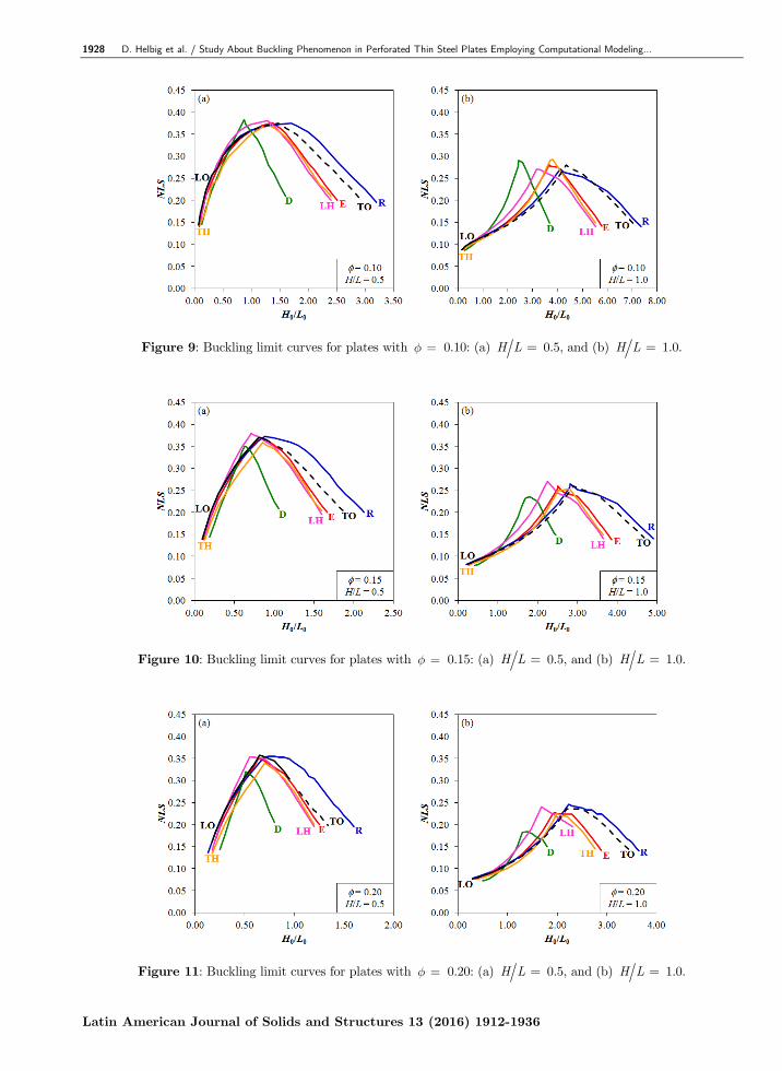
Figure 9: Buckling limit curves for plates with f = 0.10: (a) H L = 0.5, and (b) H L = 1.0.
Figure 10: Buckling limit curves for plates with f = 0.15: (a) H L = 0.5, and (b) H L = 1.0.
Figure 11: Buckling limit curves for plates with f = 0.20: (a) H L = 0.5, and (b) H L = 1.0.
D. Helbig et al. / Study About Buckling Phenomenon in Perforated Thin Steel Plates Employing Computational Modeling… 1929
Latin American Journal of Solids and Structures 13 (2016) 1912-1936
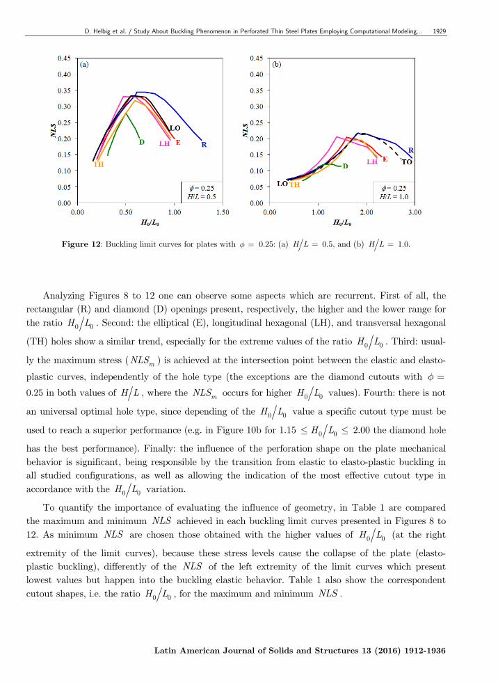
Figure 12: Buckling limit curves for plates with f = 0.25: (a) H L = 0.5, and (b) H L = 1.0.
Analyzing Figures 8 to 12 one can observe some aspects which are recurrent. First of all, the rectangular (R) and diamond (D) openings present, respectively, the higher and the lower range for the ratio 0 0H L . Second: the elliptical (E), longitudinal hexagonal (LH), and transversal hexagonal
(TH) holes show a similar trend, especially for the extreme values of the ratio 0 0H L . Third: usual-
ly the maximum stress ( mNLS ) is achieved at the intersection point between the elastic and elasto-
plastic curves, independently of the hole type (the exceptions are the diamond cutouts with f =
0.25 in both values of H L , where the mNLS occurs for higher 0 0H L values). Fourth: there is not
an universal optimal hole type, since depending of the 0 0H L value a specific cutout type must be
used to reach a superior performance (e.g. in Figure 10b for 1.15 0 0H L£ £ 2.00 the diamond hole
has the best performance). Finally: the influence of the perforation shape on the plate mechanical behavior is significant, being responsible by the transition from elastic to elasto-plastic buckling in all studied configurations, as well as allowing the indication of the most effective cutout type in accordance with the 0 0H L variation.
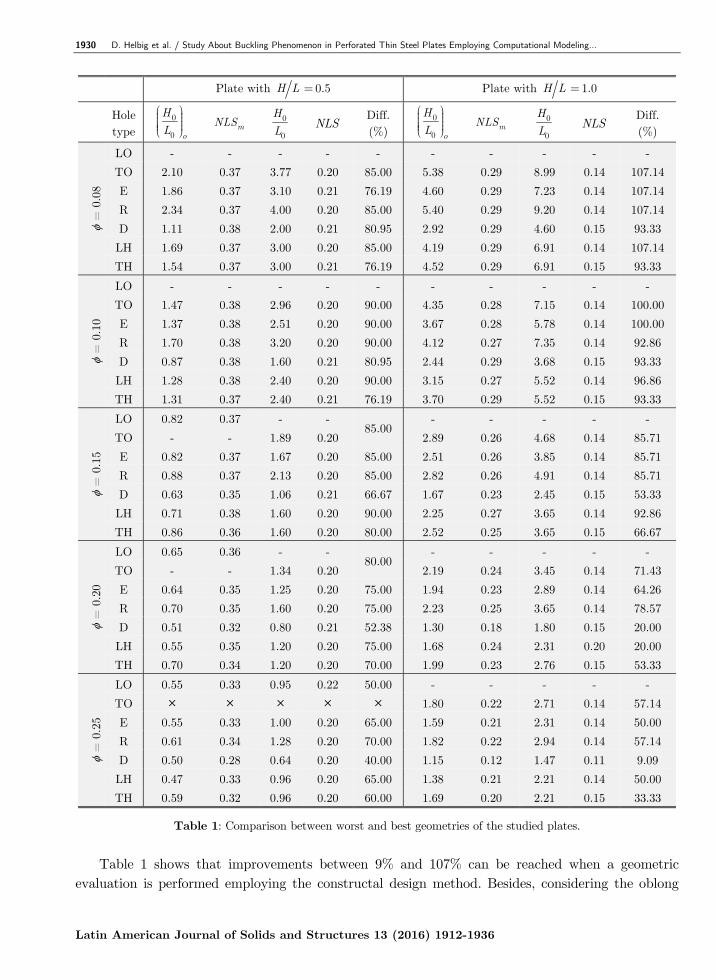
To quantify the importance of evaluating the influence of geometry, in Table 1 are compared the maximum and minimum NLS achieved in each buckling limit curves presented in Figures 8 to 12. As minimum NLS are chosen those obtained with the higher values of 0 0H L (at the right
extremity of the limit curves), because these stress levels cause the collapse of the plate (elasto-plastic buckling), differently of the NLS of the left extremity of the limit curves which present lowest values but happen into the buckling elastic behavior. Table 1 also show the correspondent cutout shapes, i.e. the ratio 0 0H L , for the maximum and minimum NLS .
1930 D. Helbig et al. / Study About Buckling Phenomenon in Perforated Thin Steel Plates Employing Computational Modeling…
Latin American Journal of Solids and Structures 13 (2016) 1912-1936
Plate with H L = 0.5 Plate with H L = 1.0
Hole type
0
0 o
H
L
æ ö÷ç ÷ç ÷ç ÷çè ø mNLS 0
0
H
L NLS
Diff. (%)
0
0 o
H
L
æ ö÷ç ÷ç ÷ç ÷çè ø mNLS 0
0
H
L NLS
Diff. (%)
=
0.0
8
LO - - - - - - - - - -
TO 2.10 0.37 3.77 0.20 85.00 5.38 0.29 8.99 0.14 107.14
E 1.86 0.37 3.10 0.21 76.19 4.60 0.29 7.23 0.14 107.14
R 2.34 0.37 4.00 0.20 85.00 5.40 0.29 9.20 0.14 107.14
D 1.11 0.38 2.00 0.21 80.95 2.92 0.29 4.60 0.15 93.33
LH 1.69 0.37 3.00 0.20 85.00 4.19 0.29 6.91 0.14 107.14
TH 1.54 0.37 3.00 0.21 76.19 4.52 0.29 6.91 0.15 93.33
=
0.1
0
LO - - - - - - - - - -
TO 1.47 0.38 2.96 0.20 90.00 4.35 0.28 7.15 0.14 100.00
E 1.37 0.38 2.51 0.20 90.00 3.67 0.28 5.78 0.14 100.00
R 1.70 0.38 3.20 0.20 90.00 4.12 0.27 7.35 0.14 92.86
D 0.87 0.38 1.60 0.21 80.95 2.44 0.29 3.68 0.15 93.33
LH 1.28 0.38 2.40 0.20 90.00 3.15 0.27 5.52 0.14 96.86
TH 1.31 0.37 2.40 0.21 76.19 3.70 0.29 5.52 0.15 93.33
=
0.1
5
LO 0.82 0.37 - - 85.00
- - - - -
TO - - 1.89 0.20 2.89 0.26 4.68 0.14 85.71
E 0.82 0.37 1.67 0.20 85.00 2.51 0.26 3.85 0.14 85.71
R 0.88 0.37 2.13 0.20 85.00 2.82 0.26 4.91 0.14 85.71
D 0.63 0.35 1.06 0.21 66.67 1.67 0.23 2.45 0.15 53.33
LH 0.71 0.38 1.60 0.20 90.00 2.25 0.27 3.65 0.14 92.86
TH 0.86 0.36 1.60 0.20 80.00 2.52 0.25 3.65 0.15 66.67
=
0.2
0
LO 0.65 0.36 - - 80.00
- - - - -
TO - - 1.34 0.20 2.19 0.24 3.45 0.14 71.43
E 0.64 0.35 1.25 0.20 75.00 1.94 0.23 2.89 0.14 64.26
R 0.70 0.35 1.60 0.20 75.00 2.23 0.25 3.65 0.14 78.57
D 0.51 0.32 0.80 0.21 52.38 1.30 0.18 1.80 0.15 20.00
LH 0.55 0.35 1.20 0.20 75.00 1.68 0.24 2.31 0.20 20.00
TH 0.70 0.34 1.20 0.20 70.00 1.99 0.23 2.76 0.15 53.33
=
0.2
5
LO 0.55 0.33 0.95 0.22 50.00 - - - - -
TO 1.80 0.22 2.71 0.14 57.14
E 0.55 0.33 1.00 0.20 65.00 1.59 0.21 2.31 0.14 50.00
R 0.61 0.34 1.28 0.20 70.00 1.82 0.22 2.94 0.14 57.14
D 0.50 0.28 0.64 0.20 40.00 1.15 0.12 1.47 0.11 9.09
LH 0.47 0.33 0.96 0.20 65.00 1.38 0.21 2.21 0.14 50.00
TH 0.59 0.32 0.96 0.20 60.00 1.69 0.20 2.21 0.15 33.33
Table 1: Comparison between worst and best geometries of the studied plates.
Table 1 shows that improvements between 9% and 107% can be reached when a geometric
evaluation is performed employing the constructal design method. Besides, considering the oblong
D. Helbig et al. / Study About Buckling Phenomenon in Perforated Thin Steel Plates Employing Computational Modeling… 1931
Latin American Journal of Solids and Structures 13 (2016) 1912-1936
openings, one can observe among the studied cases that for the plates with H L = 0.5 and f £
0.10 the best and worst shapes are obtained with the TO hole; for values of 0.15 f£ £ 0.20 the
best geometry is obtained with a LO hole while the worst configuration was defined by a TO hole; and for f ³ 0.25 the best and worst geometries are defined by the LO cutout (the TO hole was
geometrically impossible in this case). While, for the plates with H L = 1.0 the best and worst
shapes are always obtained with TO hole independently of f value.
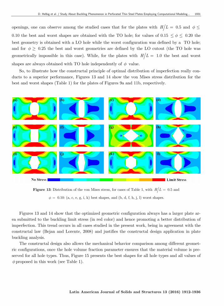
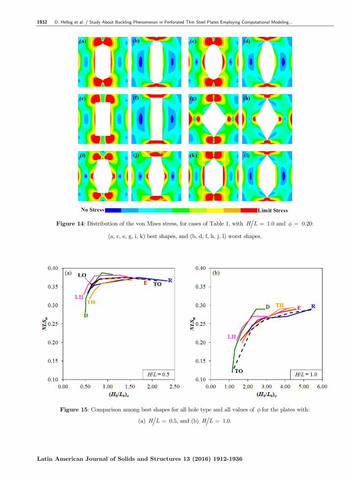
So, to illustrate how the constructal principle of optimal distribution of imperfection really con-ducts to a superior performance, Figures 13 and 14 show the von Mises stress distribution for the best and worst shapes (Table 1) for the plates of Figures 9a and 11b, respectively.
Figure 13: Distribution of the von Mises stress, for cases of Table 1, with H L = 0.5 and
f = 0.10: (a, c, e, g, i, k) best shapes, and (b, d, f, h, j, l) worst shapes.
Figures 13 and 14 show that the optimized geometric configuration always has a larger plate ar-
ea submitted to the buckling limit stress (in red color) and hence promoting a better distribution of imperfection. This trend occurs in all cases studied in the present work, being in agreement with the constructal law (Bejan and Lorente, 2008) and justifies the constructal design application in plate buckling analysis.
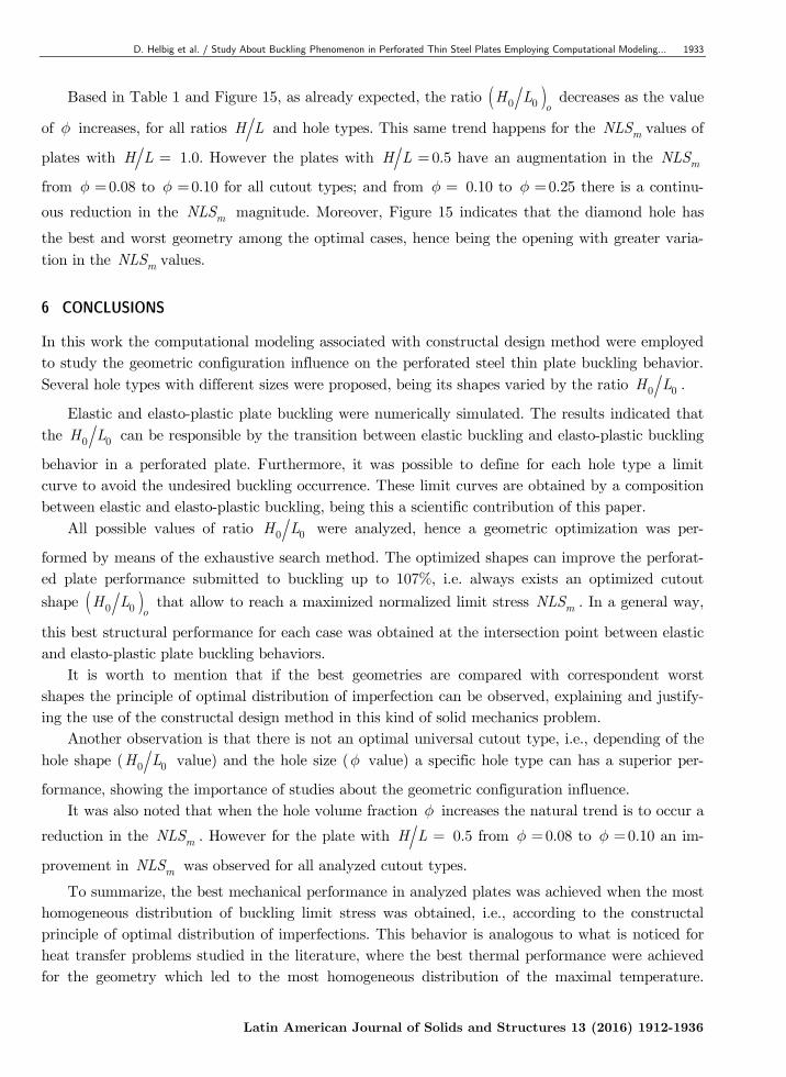
The constructal design also allows the mechanical behavior comparison among different geomet-ric configurations, once the hole volume fraction parameter ensures that the material volume is pre-served for all hole types. Thus, Figure 15 presents the best shapes for all hole types and all values of f proposed in this work (see Table 1).
1932 D. Helbig et al. / Study About Buckling Phenomenon in Perforated Thin Steel Plates Employing Computational Modeling…
Latin American Journal of Solids and Structures 13 (2016) 1912-1936
Figure 14: Distribution of the von Mises stress, for cases of Table 1, with H L = 1.0 and f = 0.20:
(a, c, e, g, i, k) best shapes, and (b, d, f, h, j, l) worst shapes.
Figure 15: Comparison among best shapes for all hole type and all values of f for the plates with:
(a) H L = 0.5, and (b) H L = 1.0.
D. Helbig et al. / Study About Buckling Phenomenon in Perforated Thin Steel Plates Employing Computational Modeling… 1933
Latin American Journal of Solids and Structures 13 (2016) 1912-1936
Based in Table 1 and Figure 15, as already expected, the ratio ( )0 0 oH L decreases as the value
of f increases, for all ratios H L and hole types. This same trend happens for the mNLS values of
plates with H L = 1.0. However the plates with H L = 0.5 have an augmentation in the mNLS
from f =0.08 to f =0.10 for all cutout types; and from f = 0.10 to f =0.25 there is a continu-
ous reduction in the mNLS magnitude. Moreover, Figure 15 indicates that the diamond hole has
the best and worst geometry among the optimal cases, hence being the opening with greater varia-tion in the mNLS values.
6 CONCLUSIONS
In this work the computational modeling associated with constructal design method were employed to study the geometric configuration influence on the perforated steel thin plate buckling behavior. Several hole types with different sizes were proposed, being its shapes varied by the ratio 0 0H L .
Elastic and elasto-plastic plate buckling were numerically simulated. The results indicated that the 0 0H L can be responsible by the transition between elastic buckling and elasto-plastic buckling
behavior in a perforated plate. Furthermore, it was possible to define for each hole type a limit curve to avoid the undesired buckling occurrence. These limit curves are obtained by a composition between elastic and elasto-plastic buckling, being this a scientific contribution of this paper.
All possible values of ratio 0 0H L were analyzed, hence a geometric optimization was per-
formed by means of the exhaustive search method. The optimized shapes can improve the perforat-ed plate performance submitted to buckling up to 107%, i.e. always exists an optimized cutout
shape ( )0 0 oH L that allow to reach a maximized normalized limit stress mNLS . In a general way,
this best structural performance for each case was obtained at the intersection point between elastic and elasto-plastic plate buckling behaviors.
It is worth to mention that if the best geometries are compared with correspondent worst shapes the principle of optimal distribution of imperfection can be observed, explaining and justify-ing the use of the constructal design method in this kind of solid mechanics problem.
Another observation is that there is not an optimal universal cutout type, i.e., depending of the hole shape ( 0 0H L value) and the hole size (f value) a specific hole type can has a superior per-
formance, showing the importance of studies about the geometric configuration influence. It was also noted that when the hole volume fraction f increases the natural trend is to occur a
reduction in the mNLS . However for the plate with H L = 0.5 from f =0.08 to f =0.10 an im-
provement in mNLS was observed for all analyzed cutout types.
To summarize, the best mechanical performance in analyzed plates was achieved when the most homogeneous distribution of buckling limit stress was obtained, i.e., according to the constructal principle of optimal distribution of imperfections. This behavior is analogous to what is noticed for heat transfer problems studied in the literature, where the best thermal performance were achieved for the geometry which led to the most homogeneous distribution of the maximal temperature.
1934 D. Helbig et al. / Study About Buckling Phenomenon in Perforated Thin Steel Plates Employing Computational Modeling…
Latin American Journal of Solids and Structures 13 (2016) 1912-1936
Therefore, the results presented in this work show the applicability and the effectiveness of the con-structal design method when applied to the structural analysis. Acknowledgements
The authors acknowledge FURG and UFRGS by the support. E. D. dos Santos, L. A. Isoldi, L. A. O. Rocha, and M. V. Real thank to CNPq by research grant.
References
Åkesson, B. (2007). Plate buckling in bridges and other structures, Taylor & Francis (London).
ANSYS. (2005). ANSYS User’s manual v10.0, Swanson Analysis System (Canonspurg).
Bejan, A. (2000). Shape and structure: from engineering to nature, Cambridge University Press (Cambridge).
Bejan, A. and Almogbel, M. (2000). Constructal T-shaped fins, International Journal of Heat and Mass Transfer 43:2101-15.
Bejan, A. and Lorente, S. (2004). The constructal law and the thermodynamics of flow systems with configuration, International Journal of Heat and Mass Transfer 47:3203-14.
Bejan, A. and Lorente, S. (2008). Design with constructal theory, John Wiley Sons (Hoboken).
Bejan, A. and Zane, J.P. (2012). Design in nature: how the constructal law governs evolution in biology, physics, technology and social organization, Doubleday (New York).
Biserni, C., Rocha, L.A.O., Stanescu, G. and Lorenzini, E. (2007). Constructal H-shaped cavities according to Bejan’s theory, International Journal of Heat and Mass Transfer 50:2132-8.
Cetkin, E., Lorente S. and Bejan A. (2010). Natural constructal emergence of vascular design with turbulent flow, Journal of Applied Physics 107:114901-1–9.
Chajes, A. (1974). Principles of structural stability theory, Prentice-Hall (New Jersey).
Cheng, B. and Zhao, J. (2010). Strengthening of perforated plates under uniaxial compression: buckling analysis, Thin-Walled Structures 48: 905-14.
Cook, R.D., Malkus, D.S. and Plesha, M.E. (1989). Concepts and applications of finite element analysis, John Wiley Sons (New York).
El-Sawy, K.M. and Martini, M.I. (2007). Elastic stability of bi-axially loaded rectangular plates with a single circular hole, Thin-Walled Structures 45: 122-33.
El-Sawy, K.M. and Nazmy, A.S. (2001). Effect of aspect ratio on the elastic buckling of uniaxially loaded plates with eccentric holes, Thin-Walled Structures 39: 983-98.
El-Sawy, K.M., Nazmy, A.S. and Martini, M.I. (2004). Elasto-plastic buckling of perforated plates under uniaxial compression, Thin-Walled Structures 42: 1083-101.
Galambos, T.V. (1998). Guide to stability design criteria for metal structures, John Wiley Sons (New York).
Gambhir, M.L. (2004). Stability analysis and design of structures, Springer-Verlag Berlin Heldberg (New York).
Gonzales, G.V., Estrada, E. da S.D., Emmendorfer, L.R., Isoldi, L.A., Xie, G., Rocha, L.A.O., Dos Santos, E.D. (2015). A comparison of simulated annealing schedules for constructal design of complex cavities intruded into con-ductive walls with internal heat generation. Energy (Oxford) 93: 372-82.
Helbig, D., Rocha, L.A.O., Da Silva, C.C.C., Dos Santos, E. D., Real, M.V., Isoldi, L.A. (2014). Numerical simula-tion and Constructal Design method applied to the study of the cutout shape Influence in the mechanical behavior of perforated plates subjected to buckling. In: Proceedings of XXXV Ibero-Latin American Congress on Computational Methods in Engineering (CILAMCE), UFC (Fortaleza).
D. Helbig et al. / Study About Buckling Phenomenon in Perforated Thin Steel Plates Employing Computational Modeling… 1935
Latin American Journal of Solids and Structures 13 (2016) 1912-1936
Isoldi, L.A., Real, M.V., Correia, A.L.G., Vaz J., Dos Santos, E.D., Rocha, L.A.O. (2013). The flow of stresses: con-structal design of perforated plates subjected to tension or buckling. In: Rocha, L.A.O., Lorente, S. and Bejan, A. (Editors). Constructal law and the unifying principle of design, Springer (New York).
Iyengar, N.G.R. (1988). Structural stability of columns and plates, John Wiley Sons (New York).
Jawad, M.H. (1994). Theory and design of plate and shell structures, Chapman & Hall (London).
Lorente, S. and Bejan, A. (2002). Combined "flow and strength" geometric optimization: internal structure in a vertical insulating wall with air cavities and prescribed strength, International Journal of Heat and Mass Transfer 45:3313-20.
Lorente, S., Lee, J. and Bejan, A. (2010). The "flow of stresses" concept: the analogy between mechanical strength and heat convection, International Journal of Heat and Mass Transfer 53: 2963-8.
Lorenzini, G., Biserni, C., Correa, R.L., Dos SANTOS, E.D., Isoldi, L.A. and Rocha, L.A.O. (2014a). Constructal design of T-shaped assemblies of fins cooling a cylindrical solid body, International Journal of Thermal Sciences 83: 96-103.
Lorenzini, G., Biserni, C., Estrada, E., Isoldi, L.A., Dos Santos, E.D. and Rocha, L.A.O. (2014b). Constructal design of convective Y-shaped cavities by means of genetic algorithm, Journal of Heat Transfer 136: 071702, 2014.
Lorenzini, G., Helbig, D., Da Silva, C.C.C., Real, M.V., Dos Santos, E.D., Isoldi, L.A. and Rocha, L.A.O. (2016a). Numerical evaluation of the effect of type and shape of perforations on the buckling of thin steel plates by means of the constructal design method, International Journal of Heat and Technology 34: 9-20.
Lorenzini, G., Helbig, D., Real, M.V., Dos Santos, E.D., Isoldi, L.A. and Rocha, L.A.O. (2016b). Computational modeling and constructal design method applied to the mechanical behavior improvement of thin perforated steel plates subject to buckling, Journal of Engineering Thermophysics 25: 1-19.
Madenci, E. and Guven, I. (2006). The Finite Element Method and applications in engineering using ANSYS®, Springer (New York).
Maiorana, E., Pellegrino, C. and Modena, C. (2009). Non-linear analysis of perforated steel plates subjected to local-ized symmetrical load, Journal of Constructional Steel Research 65: 959-64.
Maiorana, E., Pellegrino, C. and Modena, C. (2008). Linear buckling analysis of perforated plates subjected to local-ized symmetrical load, Engineering Structures 30: 3151-58.
Maquoi, R. (1995). Ultimate limit states of plate- and box-girders. In: Iványi, M. and Skaloud, M. (Editors). Steel plated structures, Springer-Verlag Wien (Udine).
Moen, C.D. and Schafer, B.W. (2009). Elastic buckling of thin plates with holes in compression or bending, Thin-Walled Structures 47: 1597-607.
Paik, J.K. (2007a). Ultimate strength of perforated steel plates under edge shear loading, Thin-Walled Structures, 45: 301-06.
Paik, J.K. (2007b). Ultimate strength of perforated steel plates under axial compressive loading along short edges, Ships and Offshore Structures 2: 355-60.
Paik, J.K. (2008). Ultimate strength of perforated steel plates under combined biaxial compression and edge shear loads, Thin-Walled Structures 46: 207-13.
Przemieniecki, J.S. (1985). Theory of matrix structural analysis, Dover Publications (Mineola).
Reis, A.H. (2006). Constructal view of scaling laws of river basins, Geomorphology 78: 201–6.
Rocha, L.A.O., Isoldi, L.A., Real, M.V., Dos Santos, E.D., Correia, A.L.G. and Lorenzini, G. (2013a). Constructal Design applied to the elastic buckling of thin plates with holes, Central European Journal of Engineering 3: 475-83.
Rocha, L.A.O., Lorente, S. and Bejan, A. (2013b). Constructal Law and the unifying principle of design, Springer (New York).
1936 D. Helbig et al. / Study About Buckling Phenomenon in Perforated Thin Steel Plates Employing Computational Modeling…
Latin American Journal of Solids and Structures 13 (2016) 1912-1936
Rocha, L.A.O., Real, M.V., Correia, A.L.G., Vaz J., Dos Santos, E.D. and Isoldi, L.A. (2012). Geometric optimiza-tion based on the Constructal Design of perforated thin plates subject to buckling, Computational Thermal Sciences 4: 119-29.
Rodrigues, M.K., Brum, R.S., Vaz, J., Rocha, L.A.O., Dos Santos, E.D. and Isoldi, L.A. (2015). Numerical investiga-tion about the improvement of the thermal potential of an Earth-Air Heat Exchanger (EAHE) employing the con-structal design method, Renewable Energy 80: 538-51.
Ross, C.T.F. (2011). Pressure vessels: external pressure technology, WoodheadPublishing(Cambridge).
Silva, V.D. (2006). Mechanics and strength of materials, Springer (New York).
Szilard, R. (2004). Theories and applications of plate analysis: classical, numerical and engineering methods, John Wiley Sons (Hoboken).
Xie, Z.H., Chen, L.G. and Sun, F.R. (2010). Constructal optimization of twice Y-shaped assemblies of fins by taking maximum thermal resistance minimization as objective, Science China Technology Science 53: 2756-64.
Yoo, C.H. and Lee, S.C. (2011). Stability of structures: principals and applications, Butterworth-Heinemann (Ox-ford).
Ziemian, R.D. (2010). Guide to stability design criteria for metal structures, John Wiley Sons (Hoboken).