Embed Size (px)
Citation preview

Journal of Engineering
journal homepage: www.joe.uobaghdad.edu.iq
Number 5 Volume 25 May 2019
*Corresponding author
Peer review under the responsibility of University of Baghdad.
https://doi.org/10.31026/j.eng.2019.05.04
2520-3339 © 2019 University of Baghdad. Production and hosting by Journal of Engineering.
)./nc/4.0-http://creativecommons.org/licenses/byNC license -This is an open access article under the CC BY
Article received: 6/5/2018
Article accepted: 7/6/2018
52
Civil and Architectural Engineering
Theoretical Analysis of Seepage through Homogeneous and
Non-homogeneous Saturated-Unsaturated Soil
Sinan Salah Abdulrazzaq Dr. Mahmood Gazey Jassam*
Civil Engineering Dept., College of Civil Engineering Dept., College of
Engineering University of Tikrit, Iraq. Engineering University of Tikrit, Iraq.
dr. [email protected] [email protected]
ABSTRACT
In this research, the program SEEP / W was used to compute the value of seepage through the
homogenous and non-homogeneous earth dam with known dimensions. The results show that the
relationship between the seepage and water height in upstream of the dam to its length for
saturated soil was nonlinear when the dam is homogenous. For the non-homogeneous dam, the
relationship was linear and the amount of seepage increase with the height of water in upstream
to its length. Also the quantity of seepage was calculated using the method of (Fredlund and
Xing, 1994) and (Van Genuchten, 1980) when the soil is saturated – unsaturated, the results
referred to that the higher value of seepage when the soil is saturated and the lowest value of
seepage when using Van Genuchten method for both homogeneous and non-homogeneous earth
fill dams. Also relationship for the seepage (Q) with the curve fitting parameter (a) for sand, silt
and clay soil was nonlinear when the dam is homogenous with constant variables (n, m) and the
amount of seepage increase with increasing value of (a). The amount of seepage for a
nonhomogeneous dam with a different value of (Kshell to Kcore) was calculated and then compared
with the value of (K equivalent) which was equal to average (Kshell and Kcore) for the homogenous
dam. The results show that when the average between (Kshell and Kcore) is ≤ 100 the difference
was small between the quantity of the seepage calculated. For simplicity of the solution process,
it can be replaced non-homogeneous dam by a homogenous dam with (K eq) when the values of
Kshell and Kcore are less than or equal to 100.
Keywords: seepage, homogenous, nonhomogeneous, saturated-unsaturated soil, curve fitting
parameters
ير مشبعة متجانسة وغير متجانسةغ-ري للتسرب خلال تربة مشبعةظتحليل ن
سنان صلاح عبد الرزاق .د. محمود غازي جسام م
قسم الهندسة المدنية قسم الهندسة المدنية
الخلاصة
.معلومرة بأبعرا متجران متجران غييرر ترابري سرد خرل التسرر قيمة لمعرفة SEEP/W البرنامج استخدام تم البحث هذا في
ليسر للتربرة المبربعة مرن نهاةرة ارتفراع المراء الر نهاةرة السرد طولر السد الر مقدمة فيالماء بين ارتفاعحيث غجد ان العلقة
غان مقدار التسرر ةرا ا مرز اا ةرا ارتفراع المراء خطية العلقة فكان متجان الغير سدلا اما متجان السد ةكون عندما خطية
(Van Genuchten1980)غ ) (Fredlund and Xing1994طرةقرةبموجر التسرر ترم اةجرا مقردار كرذل .امرام السرد
قيمررة غأغطررأ كليررا مبرربعة التربررة تكررون عنرردما للتسررر قيمررة اعلرر انالنتررا ج بينرر غ مبرربعة ييررر- مبرربعة التربررة تكررون عنرردما
Journal of Engineering Volume 25 May 2019 Number 5
53
كرذل . (ةمتجانس غالغير ةالمتجانسمن السدغ الترابية )لكل النوعين Van Genuchten) ) طرةقة كان باستخدام للتسر
السرد ةكرون عنردما خطيرة ييرر كانر حيرث غالطينرة غالغرةنيرة الرمليرة للتربة( a) متغيرمز ال (Q) تسر لا تم اةجا علقة بين
ترم .الرمليرة غالغرةنيرة غالطينيرة للترر a) قيمرة )غان مقدار التسر ةا ا مز اا ةرا m, n).) ات مز ثبوت المتغير متجان
مررز القرريم المحسرروبة عنرردما تكررون قيمررة غقورنرر (coreKغ shellK)اةجررا كميررة التسررر لسررد ييررر متجرران لقرريم مختلفررة مررن
المعرد كرون ةبينر النترا ج انر عنردما غقرد لسرد متجران (coreKغ llsheK( ةقيمرالتي هي معرد غي القيمة المكافئة النفاذةة تسا
متجران الغيرر سرد ال نةمكرن التعروةع عر التحليرل غعلير لتسرهيل فان الفرق قليل بين قيم التسر المحسوبة 100بين القيمتين
) Kshell /Kcore≤ 100)ةكون عندما بسد متجان بنفاذةة مكافئة
.معررررراملت مسرررررار المنحنررررري ‘مبررررربعة ييرررررر-مبررررربعةتربرررررة ‘ييرررررر متجررررران ‘متجررررران ‘التسرررررر : ةالكلماااااائ الر سااااا
1. INTRODUCTION
Several factors affect to seepage in the soil which is hydraulic conductivity of the soil and the
pressure gradient, essentially the combination of factors acting on water. The homogenous and
non-homogeneous earth fill dams have seepage existent from water percolating slowly of the
dam and its foundation. Many problems from seepage and failures of earth-fill dams have
occurred due to inadequate seepage control Omofunmi, et al., 2017. Therefore, many numbers
of theories have been used for the solution of seepage problems, Dupuit's, Schaffernak-
VanIterson, Casagrande's and other solutions to determine the quantity discharge through 2D
homogeneous earth fill dams when the bases are impervious. Jairry, 2010.
The first figure who proposed the solution of the linear partial differential equation of flow was
by Casagrande in 1937 the method known as "the graphical flow net method". According to this
method, the soil is homogeneous and isotropic and that water flows only in the saturated zone.
The boundaries of the flow region must be defined in terms of head or no flow. By Casagrande
proposed the flow net solution. It was for simple unconfirmed flow cases without flux boundary
conditions. The digital computer to solve complex seepage problems has appeared in late 1960.
The development and application of such a thing take place. Proposed an alternative model of
flow through both saturated and unsaturated soil regions. Developing this device and its
combination with the finite element method help to solve the steady-state and transient saturated-
unsaturated seepage problems. The computer programs are intended to solve saturated-
unsaturated modeling in engineering practice, examples being, MODFLOW and SEEP/W
seepage analysis for unsaturated soils is characterized by a partial differential equation that is
non- linear and soil properties that can be highly non-linear .
Consequently, the modeling of saturated and unsaturated soil systems becomes a challenge. The
first challenge to face is to develop a numerical software package that ensures convergence in
case of solving seepage problems with both saturated and unsaturated soil systems. This case
lurks in solving problems unsaturated soil, Fredlund, 1996. Because of the fast development
regarding computer in the last two decades for solving complex problems, unsaturated soil
problem began to involve the soil properties that are highly non-linear, such as coefficient of
permeability and water storage function. The partial differential equations to be solved become
highly nonlinear and require the input from persons specially trained in the area of mathematics.
This encourages the use of general partial differential equation solvers that are designed to solve
equations from any area of engineering, Thieu, et al., 2001.
Kamanbedast and Delvari, 2012, used Ansys and Geo-Studio Software to analysis leakage and
stability of Maroon dam that location north of Bahaman. The results showed that the seepage

Journal of Engineering Volume 25 May 2019 Number 5
54
results in ANSYS were 18% lower than the results obtained from Geo-Studio. The slope stability
results were similar for both programs.
Majeed, 2015, studied flow and deformation analysis of zone earth dam used finite element
method. It concluded that finite element is the best tool for analyzing seepage flow in an earth-
fill dam.
Jamel, 2016, studied the analysis and estimation of seepage through homogenous earth dam
without a filter. Results show that when comparing the suggest equation with the artificial neural
network (ANN) the error is less than 3% and with SEEP/W results less than 2% error, Dupuit’s
solution has more than 20% error and Casagrande’s solution has more than 15% error.
The understanding of seepage flow makes it easier for designers to the selection of the type of
dam that should be chosen according to use or purpose for which it was constructed for (storage
or diversion or retention) the water.
The seepage through the soil depend on several factors, the most important of which is hydraulic
conductivity, when the soil is saturated and their values considered a key for identifying the type
of soil and constant for each type of soil but when the soil is saturated-unsaturated it can be
calculated by method of Fredlund and Xing or Van Genuchten method.
The relationship between the water content and the matric suction represent a curve, the path of
the curve can be defined by parameters (m, n. a) that value depends on the soil type.
The present study considered some important factors that affect seepage through earth dams such
as the method of prediction of soil water characteristic curve and curve fitting parameter by using
finite element method (FEM) in seepage analysis that makes the solution of seepage problems
faster and complex leakage problems can be solved.
2. SEEP/W PROGRAM
SEEP/W can be defined as a finite element software product. It is a subprogram of Geo-Studio,
used for analyzing groundwater seepage and access pore water pressure dissipation problems
within porous materials such as soil and rock. Considering analyses ranging from simple
saturated steady state problems to sophisticated, saturated and unsaturated time-dependent
problems. For geotechnical, civil, hydrogeological and mining engineering projects SEEP/W is
suitable and can be applied confidently, Irzooki, 2016.
The following equation used in the software program SEEP/W
𝜕
𝜕𝓍(k𝓍
𝜕𝘩
𝜕𝑥)+
𝜕
𝜕𝘺(k𝘺
𝜕𝘩
𝜕𝘺) +Q=
𝜕𝜃
𝜕𝑡 (1)
Where:
h is total head
kx is hydraulic conductivity in the x-direction.
k𝘺 is hydraulic conductivity in the 𝘺-direction.
Q is applied boundary seepage
𝜃 is volumetric water content
𝑡 is time
So that equation (1) modified to the following form for steady-state situations

Journal of Engineering Volume 25 May 2019 Number 5
55
𝜕
𝜕𝓍(k𝓍
𝜕𝘩
𝜕𝓍)+
𝜕
𝜕𝘺(k
𝜕𝘩
𝜕𝘺) + Q=0 (2)
For steady state condition, the seepage entering and leaving an elemental volume at all time is a
same. Abbas, 2017, SEEP/W program was used by many previous workers and they worked
different seepage problems, Irzooki, 2016.
3. SOIL SUCTION
The development soil suction theories take place in relation to the soil–water plant system. The
relation between suction and engineering properties of the soil increases importance of soil
suction in the mechanical behavior of unsaturated soils. Another term is used alternatively to soil
suction is the free energy state of soil water Edlefsen and Anderson, 1943 cited in Fredlund
and Rahardjo, 1993.
The partial vapor pressure of the soil water enables to measure the free energy of the soil water,
this will prove the total connection or the relationship between relative humidity and soil suction
which is equivalent suction derived from the measurement of the partial pressure of the water
vapor in equilibrium with the free pore, Sood, 2005.
Soil suction has two components, a matric and matrix suction .Matric suction or capillary
pressure refers to the difference between the pore- air pressure and the pore- water pressure (ua-
uw). This suction is equal and is derived from the measurement of the partial pressure of water
vapor in equilibrium with the soil water which is relative to the partial pressure of the water
vapor in equilibrium with a solution identical in composition with the soil water. On the other
hand, osmotic (or solute) component of free energy is the equivalent suction just like matric
solution. The difference is that osmotic suction is relative to the partial pressure of water vapor in
equilibrium with free pore water, Fredlund and Rahardjo, 1993. Acording to Fredlund, 1994,
osmatic suction is a function of the amount of dissolved salts in the pore Fluid. For Fredlund
and Xing, 1994 at high suction (i-e greater than 1500 kPa), matric suction and total suction can
be considered equivalent.
4. SOIL WATER CHARACTERISTIC CURVE
The relationship between water content and suction of a soil is known as “The soil-water
characteristic curve” (SWCC). Form the hydraulic and physical point of view; it is the important
parameter in the application of unsaturated soil mechanics to geotechnical and geoenvironmental
engineering. SWCC or his parameter estimates the soil properties such as coefficient of
permeability, shear strength and volume change to describe the engineering behavior of
unsaturated soil. There are two types of (SWCC). The first is (desorption curves) when the soil
transfers from the saturated state to drying state under the effect of suction pressure. The second
type is the (adsorption curve) when the soil transfers from drying state to saturation state. Many
designations have been used to measure the amount of water in the soil. There are three basic
measures, the volumetric water content, θw, gravimetric water content, w, and the degree of
saturation, S. Volumetric water content has most commonly used. Fig. 1 shows the typical
(SWCC) for silty soil. The (SWCC) contains three elements, the air entry value, the saturated
volumetric water content (θs) and the residual volumetric water content (θr). The first stands for

Journal of Engineering Volume 25 May 2019 Number 5
56
the value of suction pressure when the water starts to drainage out of the soil sample and
represents the most significant point in (SWCC). The second element stands for the ratio
between the volumes occupied by water to total volume, this values equal to soil porosity while
the third stands for the water content at which a high suction pressure is required to dissipate
additional water from soil sample, Fig. 1 shows these three, Fredlund, et al., 1996.
Figure 1. Typical soil- water characteristic curve for a silty soil
(After Fredlund and Xing, 1994).
5. HYDRAULIC CONDUCTIVITY
The hydraulic conductivity of soils depends on several factors: fluid viscosity, pore-size
distribution, grain- size distribution, void ratio, the roughness of mineral particles and degree of
soil saturation. In clayey soils, structure plays an important role in hydraulic conductivity. Other
major factors that affect the permeability of clays are the ionic concentration and the thickness of
layers of water held to the clay particles. The value of hydraulic conductivity (k) varies widely
for different soils. Some typical values for saturated soils are given in table (1), Das, 2006.
Table 1. Hydraulic conductivity of saturated soils.
Soil type cm/sec ft/min
Clean gravel 1.0-100 200-2.0
Coarse sand 0.1-1.0 2.0-0.02
Fine sand 0.01-0.001 0.02-0.002
Silty clay 0.001-0.00001 0.002-0.00002
Clay >0.000001 < 0.000002
The hydraulic conductivity (k) of an unsaturated soil is not a constant and depends on the
volumetric water content (θw) or the matric suction, (ψ), Fattah, et al., 2014.
The hydraulic conductivity in an unsaturated soil is considerably influenced by the extent of soil
saturation (or the content of water). Water runs through the spaces of pores full of water, thus,
the ratio of voids full with water is a vital factor. When the soil grows unsaturated, air initially

Journal of Engineering Volume 25 May 2019 Number 5
57
substitutes some of the water in the bigger pores which makes the water runs through the minor
pores with an enlarged flow path sinuosity. Another matric suction increase of soil results in
another reduction in the volume of pores filled with water. This results in additional resistance to
the flow of water when the air-water line comes nearer and nearer to the particles of soil.
Consequently, the hydraulic conductivity, in terms of the phase of liquid (water), declines
quickly when the space existing for the flow of water decreases.
As Fig. 2 shows, the desiccation (desorption) and/or the moistening (absorption) of most soils
SWCCs results in hysteretic conduct, Pham, et al., 2005, for the similar value of suction, the soil
may keep more water in the desiccating procedure than in the moistening procedure
.
Figure 2. Typical soil-water characteristic curves
(After Gallage, et al., 2013).
Thus, the function of unsaturated soil hydraulic conductivity, measured after the desiccating and
moistening procedure, would display hysteresis as exposed to the matric suction, van Dam, et
al., 1996. Because of the large consumption of time necessary for measuring the function of
hydraulic conductivity after the moistening procedure, it is usually measured after the desiccating
procedure, Agus, et al., 2005.
In order to measure the hydraulic conductivity precisely and correctly at little suction values,
thus, it is significant to get a parameter that utilizes the constant-state method and has a more
costly and vigorous system of measurement. Nevertheless, measuring the unsaturated hydraulic
conductivity in the laboratory is consuming time and expensive, because it needs special devices
and equipment as well as the service of a skillful technical individual. Consequently, many
theoretical (indirect) methods are suggested by scholars to forecast the unsaturated soils
hydraulic conductivity, Fredlund, et al., 1994 and van Genuchten, 1980.

Journal of Engineering Volume 25 May 2019 Number 5
58
6. PARAMETRIC STUDY FOR HOMOGENEOUS EARTH DAM
After the construction of an earth dam according to a particular design, the height of the water is
considered variable and the hydraulic conductivity is constant for the saturated soil but it is
different in the saturated-unsaturated soil. From this principle, SEEP/W software program was
used to study seepage when the soil is saturated and saturated-unsaturated through homogeneous
earth dam. Fig. 3 is the typical cross- section for homogenous earth dam considered in this study.
From Fig. 3, the possible variables affecting the quantity of seepage (Q) are:
Figure 3. Typical cross-sections for homogenous earth dam profile.
H=higth of the earth dam (15m)
hw=height of the water in the upstream (m)
L= Length from end height water to end dam
Cd=crest width of the dam (8m)
b= triangle base(26m)
In this research, the effect of heights of water in upstream (9, 10, 11, 12) and (L) (44.4, 42.667,
40.933, 39.2) was studied and the amount of seepage through the dam with constant hydraulic
conductivity (k=0.1728 m/days) and saturated material was computed. Also, the analysis for
saturated-unsaturated material using the data according to range value in Table 2 are performed,
where n and α refer to the soil- water characteristic curve and hydraulic conductivity function
modeling constants, Sr is the residual degree of saturation and Ks is saturated hydraulic
conductivity. The n parameter is required in many SWCC hydraulic conductivity function
models to capture the pore size distribution of the soil.
Table 2. Representative Hydrologic parameter for sand, silt, and clay, Ning Lu and William,
2004.
Soil type n(dimensionless) α(kpa-1) Sr (%) Ks(m/s)
Sand 4 -8.5 0.1 – 0.5 5-10 10-2-10-5
Silt 2 -4 0.01-0.1 8-15 10-6-10-9
Clay 1.1 -2.5 0.001- 0.1 10-20 10-8-10-13

Journal of Engineering Volume 25 May 2019 Number 5
59
Three types of soil are used with curve fitting parameter. a, n, and m as shown in Table 3.
Fredlund and Xing and van Geunchten methods were applied with different values of (a)
parameter for each soil with constant n, m, and constant hydraulic conductivity according to
Table 3.
Table 3. Curve fitting parameter of used soil, Fredlund and Xing, 1994.
Soil type a n m(Fr) Ks(m/day) Sr
sand 1.799 4.524 1.157 o.864 0.08
Silt 1.948 2.708 1.084 0.00864 0.1
clay 15150 1.101 0.865 0.0000864 0.15
7. PARAMETRIC STUDY FOR NON-HOMOGENEOUS EARTH DAMS
One of the most important components in dam designing is the dam core. The dam core is a
significant factor in caulking and controlling the dam body from seepage, Karampoor, and
Riazi, 2015. Fig.4 shows the sample models of a nonhomogeneous dam, the possible variables
affecting the quantity of seepage (Q) are:
Figure 4. Sample model of non- homogeneous earth dam.
H= higth of the earth dam (15m)
w = crest width of the dam (8m)
x= width base of the dam (60m)
b= crest width of the dam core (3m)
d=width the base of the dam core (14m)
the effect of different heights of water in upstream (9, 10, 11, 12), with different values of (L)
(44.4, 42.667, 40.933, 39.2) on amount of seepage through the dam with constant hydraulic
Journal of Engineering Volume 25 May 2019 Number 5
60
conductivity (Kshell=0.864 m/day and Kcore=0.0000864) m/day) for saturated soil was studied.
Also, saturated-unsaturated analysis was calculated using the values shown in Table 4.
Table 4. Curve fitting parameter of used soils for the nonhomogeneous dam, Fredlund and
Xing, 1994.
No Soil type a n m Ks(m/day) Sr
1- Silt 1.948 2.708 1.084 0.0864 0.1
2- Clay 15150 1.101 0.865 0.0000864 0.15
8. RESULTS AND DISCUSSION
The effect of each variable on amount seepage through homogeneous and non-homogenous earth
dams can be seen as follows:
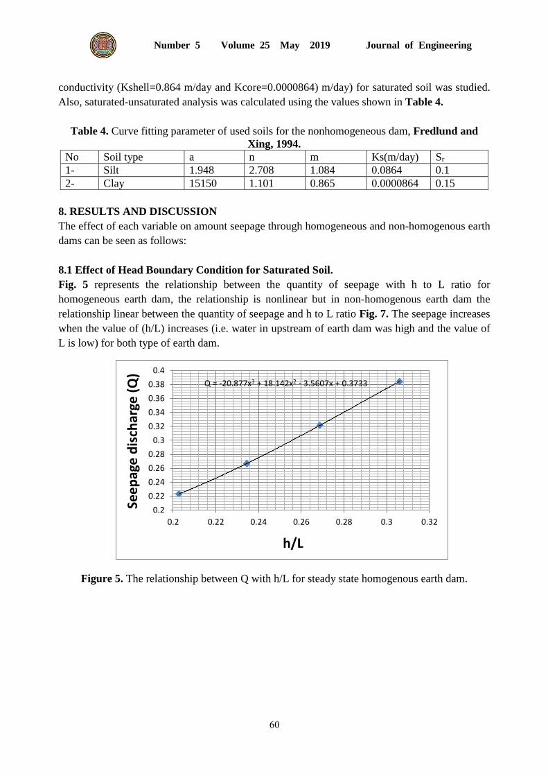
8.1 Effect of Head Boundary Condition for Saturated Soil.
Fig. 5 represents the relationship between the quantity of seepage with h to L ratio for
homogeneous earth dam, the relationship is nonlinear but in non-homogenous earth dam the
relationship linear between the quantity of seepage and h to L ratio Fig. 7. The seepage increases
when the value of (h/L) increases (i.e. water in upstream of earth dam was high and the value of
L is low) for both type of earth dam.
Figure 5. The relationship between Q with h/L for steady state homogenous earth dam.
Q = -20.877x3 + 18.142x2 - 3.5607x + 0.3733
0.2
0.22
0.24
0.26
0.28
0.3
0.32
0.34
0.36
0.38
0.4
0.2 0.22 0.24 0.26 0.28 0.3 0.32
See
pag
e d
isch
arge
(Q
)
h/L

Journal of Engineering Volume 25 May 2019 Number 5
61
Figure 6. The relationship between (Q) with (H/L) for steady state non-homogenous
earth dam.
8.2 Effect of Method of Prediction SWCC on Seepage through Soil.
For homogenous earth dam, Fig.7 illustrates the relationship between the type of analysis
with seepage (Q), the highest value of (Q) when the soil is saturated and smallest value is
when using the method of (VG.) for all type of soil (sand, silt, and clay).
Figure 7. Comparison between methods of prediction of SWCC on seepage through saturated-
unsaturated soil for different type of soil.
y = 0.5479x + 0.0596
0.15
0.2
0.25
0.2 0.23 0.26 0.29 0.32
See
pag
e (
Q x
0.0
1)
X=h/L

Journal of Engineering Volume 25 May 2019 Number 5
62
8.3 Effect of Type of Analysis
For non-homogeneous earth dam, Fig. 8 represents the relationship between seepage (Q) with the
method of analysis, the result shows that the value of seepage is highest for saturated and
smallest value is obtained when using of Van Genuchten method.
Figure 8. The relationship between seepage (Q) with the method of analysis.
8.4 Effect of Curve Fitting Parameter on the Seepage
To study the effect of curve fitting parameters on seepage through different types of soil,
different values of a parameter for each soil are used with constant n and m and constant
hydraulic conductivity as show in Table 4.
Table 4. Curve fitting parameter of used soils for homogenous dam
Sr Ks m/day m( Fr.) n a ( kPa) Soil type
0.08 0.864 1.157 4.524 0.1 Sand
1
1.799
0.1 0.00864 1.084 2708 1.948 Silt
10
25
0.15 0.0000864 1 1.5 625 Clay
1000
1500
Journal of Engineering Volume 25 May 2019 Number 5
63
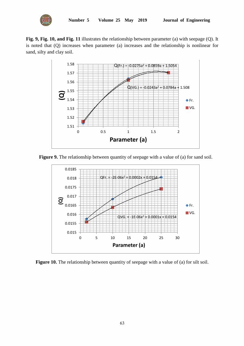
Fig. 9, Fig. 10, and Fig. 11 illustrates the relationship between parameter (a) with seepage (Q). It
is noted that (Q) increases when parameter (a) increases and the relationship is nonlinear for
sand, silty and clay soil.
Figure 9. The relationship between quantity of seepage with a value of (a) for sand soil.
Figure 10. The relationship between quantity of seepage with a value of (a) for silt soil.
Q(Fr.) = -0.0275a2 + 0.0859a + 1.5054
Q(VG.) = -0.0243a2 + 0.0784a + 1.508
1.51
1.52
1.53
1.54
1.55
1.56
1.57
1.58
0 0.5 1 1.5 2
(Q)
Parameter (a)
Fr.
VG.
QFr. = -2E-06x2 + 0.0002x + 0.0154
QVG. = -1E-06x2 + 0.0001x + 0.0154
0.015
0.0155
0.016
0.0165
0.017
0.0175
0.018
0.0185
0 5 10 15 20 25 30
(Q)
Parameter (a)
Fr.
VG.

Journal of Engineering Volume 25 May 2019 Number 5
64
Figure 11. The relationship between the quantity of seepage with a value of (a) for clay soil.
8.5 Effect of (Kshell/Kcore) of Soil
The values of hydraulic conductivity of shell and core soil for nonhomogeneous dam within the
limit shown in Table 6 are compared with an equivalent (Kequ) = (Kshell+Kcore)/2. Fig. 12
illustrates the relationship between the quantities of seepage (Q) with hydraulic conductivity. The
result shows that the difference is high for the first and second case (42% and 202%) whereas the
difference is very low in case three when (Kshell and Kcore) =100 (4%) therefore, for simplicity
equivalent hydraulic conductivity can be used successfully when Kshell/Kcore ≤ 100.
Table 6. Hydraulic conductivity of shell and core of used soils.
Soil type of
shell
Kshell(m/day) Soil type of core Kcore(m/day) Kshell/Kcore Kequ(m/day)
Find sand 0.864 Clay 0.0000864 10000 0.4320432
Silt clay 0.0864 0.0000864 1000 0.0432432
0.00864 0.0000864 100 0.0043632
Q (Fr.) = -2E-12x2 + 7E-09x + 0.0002
Q (VG.) = 4E-12a2 - 7E-09a + 0.0002
0.000168
0.000169
0.00017
0.000171
0.000172
0.000173
0.000174
0.000175
0.000176
0.000177
0.000178
0.000179
500 700 900 1100 1300 1500 1700
(Q)
Parameter (a)
Fr.
VG.

Journal of Engineering Volume 25 May 2019 Number 5
65
Figure 12. The relationship between the quantity of seepage with a value of hydraulic
conductivity
9. CONCLUSIONS
The following main conclusions can be summarized as:-
The quantity of seepage through homogeneous and non-homogeneous earth dam is
increased with increasing ratio of height water in upstream to length (from the end of
water height to end of earth fill dam).
The highest amount of seepage through homogeneous and non-homogeneous earth dam
is for saturated soil and lowest value when using van Genuchten method
The quantity of seepage is increased when increasing the parameter (a) in sand, silt, and
clay.
The quantity of seepage is increased when increasing the value Kshell/Kcore.
9. REFERENCES
Abbas, J. k., 2017, Determination of flow through homogeneous earth dams with triangular
toe filter, Tikrit Journal of engineering sciences. Vol. 24, No. 1 pp.81-88.
Al-Damluji, O. A., Fattah, M. Y., and Al-Adthami, R. A. 2004, Solution of two-dimensional
steady-state flow field problems by the boundary element method, Journal of Engineering
and Technology, Vol. 23, No. 12, PP. 750-766.
Agus, S. S., Leong, E. C., Rahardjo, H., 2005, Estimating permeability functions of
Singapore residual soils, Engineering Geology 78, pp-119–133.
Al.Jairry, H. H., 2010, 2D-Flow Analysis Through Zoned Earth Dam Using Finite Element
Approach, Eng. and Tech. Journal, Vol. 28, No. 21, PP. 6315-6324.

Journal of Engineering Volume 25 May 2019 Number 5
66
Das, B.M., 2006, Principles of Geotechnical Engineering, 5th Publication United States.
Fattah, M. Y., Ahmed, M. D. and Ail, N. A., 2014, Prediction of Coefficient of permeability
of Unsaturated soil, Journal of Engineering Baghdad vol. 20 PP. 33-48.
Fredlund, D.G. and Rahardjo, H., 1993, An overview of unsaturated soil behavior,
proceeding of ASCE specialty series on unsaturated soils properties, Dallas, Texas, October
24-28, pp.1-13.
Fredlund, D.G., 1994, Visualization of the word of soil mechanics, presented to the: Sino-
Candian symposium on expansive soils/unsaturated soils, Wuhan, China.
Fredlund, D. G. and Xing, A., 1994, Equations for the soil- water characteristic curve,
Canadian Geotechnical Journal. Vol. 31, No. 3, pp.521-532
Fredlund, D. G., Xing, A. and Huang, S., 1994, Predicting the permeability function for
unsaturated soils using the soil – water characteristic curve, Canadian Geotechnical
Journal. Vol. 31 No. 3 pp.533-546
Fredlund, M.D., Sillers, W.S., Fredlund, D.G. and Wilson, G.W., 1996, Design of a
knowledge-based system for unsaturated soil properties, 3rd Canadian Conference on
Computing in Civil and Building Engineering, Montreal, Quebec.
Gallage, C., Kodikara, J. and Uchimura, T., 2013, Laboratory measurement of Hydraulic
conductivity functions of two unsaturated sandy soils during drying and wetting processes,
Journal homepage Soils and Foundations, Vol. 53, No. 3, pp.417-430.
Irzooki, R. H., 2016, Computation of Seepage through homogenous earth dam with
horizontal Toe drain, Eng. and Tech. Journal. Vol. 34, No. 3, PP. 430-440.
Jamel, A. A., 2016, Analysis and Estimation of Seepage through Homogenous Earth Dam
without Filter, Diyala Journal of Engineering Sciences. Vol. 9, No. 2, PP. 38-49
Kamanbedast, A., and Delvari, A., 2012, Analysis of Earth Dam Seepage and Stability
Using Ansys and Geo-Studio Software, World Applied Science Journal, No. 9, Vol. 17, pp.
1087-1094.
Karampoor, F. and Riazi, R., 2015, Investigation the effect of clay core in seepage from non-
homogenous earth dams using SEEP/W Model, Journal of scientific research and
development, No. 2, Vol.5, PP. 280 285.
Majeed, Q. G., 2015, Flow and deformation analysis of zoned earth dam by the finite element
method, Diyala Journal of Engineering Sciences, Vol. 08, No. 03, pp. 38-62

Journal of Engineering Volume 25 May 2019 Number 5
67
Ning Lu and William J. Likos, 2004, Unsaturated soil mechanics, Published simultaneously
in Canada.
Omofunmi, O. E., Kolo, J. G., Oladipo, A. S., Diabana, P. D., and Ojo, A. S., 2017, A
Review on Effects and Control of Seepage through Earth-fill Dam, Current Journal of
Applied and Technology, Vol. 22, No. 1, PP. 1-11.
Pham, H.Q., Fredlund, D. G., Barbour, S. L., 2005, A study of hysteresis models for soil–
water characteristic curves, Canadian Geotechnical Journal 42, pp. 1548–1568.
Sood, E., 2005, Determination of the diffusion coefficient for unsaturated soils, M. Sc.
Thesis, Texas A&M University.
Thieu, N. T. M., Fredlund, M. D., Fredlund, D.G., and Hung, V. Q., 2001, Seepage
modeling in a saturated/unsaturated soil system, International conference on management of
the land and water Resources, Hanoi, Vietnam, October 20-22, pp. 49-56.
van Dam, J. C., Wosten, J. H. M., Nemes, A., 1996, Unsaturated soil water movement in
hysteretic and water repellent field soil, Journal of Hydrology 184 (3-4) pp.153-173.
Van Genuchten, M. T., 1980, A closed-form equation for predicting the hydraulic
conductivity of unsaturated soils, Soil Society of America Journal 44, 892-898.