Embed Size (px)
DESCRIPTION
PERMEABILITY? Overview of Underground Water Flow? Permeability? Theory? Laboratory and Field Tests? Empirical Correlations? Equivalent Permeability in Stratified SoilSEEPAGE? Laplace’s Equation of Continuity? Continuity Equation for Solution of Simple Flow Problems? Flow Nets? Seepage Calculation? Seepage pressure and Uplift Pressure? Seepage through an Earth Dam
Citation preview
University of Anbar College of Engineering Civil Engineering Department Iraq-Ramadi
Asst. Prof. Khalid R. Mahmood (PhD.)
91
Permeability and Seepage
Topics 1. Permeability
Overview of Underground Water Flow
Permeability Theory Laboratory and Field Tests Empirical Correlations Equivalent Permeability in Stratified Soil
W.T.
Datum
hA = total head
W.T.
h = hA - hB
Impervious Soil
Impervious Soil
pervious Soil
hB= total head
University of Anbar College of Engineering Civil Engineering Department Iraq-Ramadi
Asst. Prof. Khalid R. Mahmood (PhD.)
92
2. Seepage Laplace’s Equation of Continuity Continuity Equation for Solution of Simple Flow Problems Flow Nets Seepage Calculation Seepage pressure and Uplift Pressure Seepage through an Earth Dam
University of Anbar College of Engineering Civil Engineering Department Iraq-Ramadi
Asst. Prof. Khalid R. Mahmood (PhD.)
93
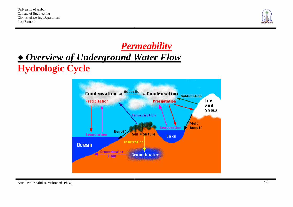
Permeability Overview of Underground Water Flow
Hydrologic Cycle
University of Anbar College of Engineering Civil Engineering Department Iraq-Ramadi
Asst. Prof. Khalid R. Mahmood (PhD.)
94
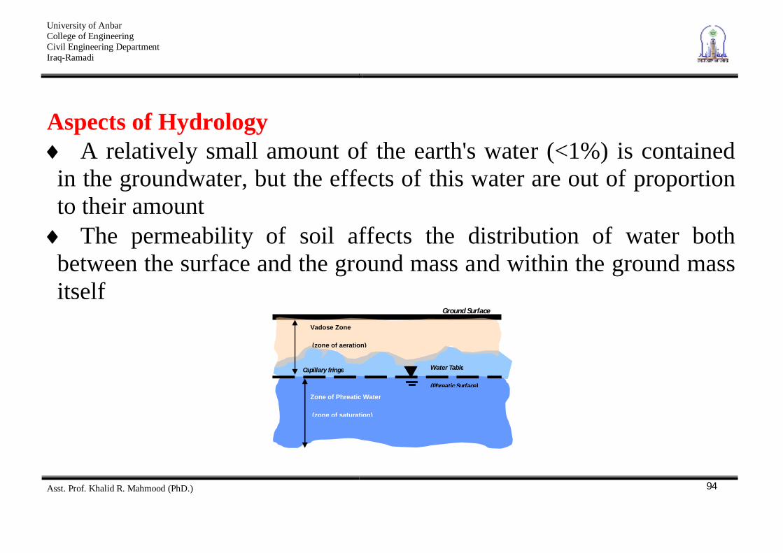
Aspects of Hydrology A relatively small amount of the earth's water (<1%) is contained
in the groundwater, but the effects of this water are out of proportion to their amount The permeability of soil affects the distribution of water both
between the surface and the ground mass and within the ground mass itself
Vadose Zone
(zone of aeration)
Ground Surface
Capillary fringe Water Table
(Phreatic Surface)
Zone of Phreatic Water
(zone of saturation)
University of Anbar College of Engineering Civil Engineering Department Iraq-Ramadi
Asst. Prof. Khalid R. Mahmood (PhD.)
95
Permeability Definition-
The property of soils
allows water to pass through them at some rate. is a product of the granular nature of the soil, although it can
be affected by other factors (such as water bonding in clays) Different soils have different permabilities, understanding of
which is critical to the use of the soil as a foundation or structural element
Soil and rock are porous materials
University of Anbar College of Engineering Civil Engineering Department Iraq-Ramadi
Asst. Prof. Khalid R. Mahmood (PhD.)
96
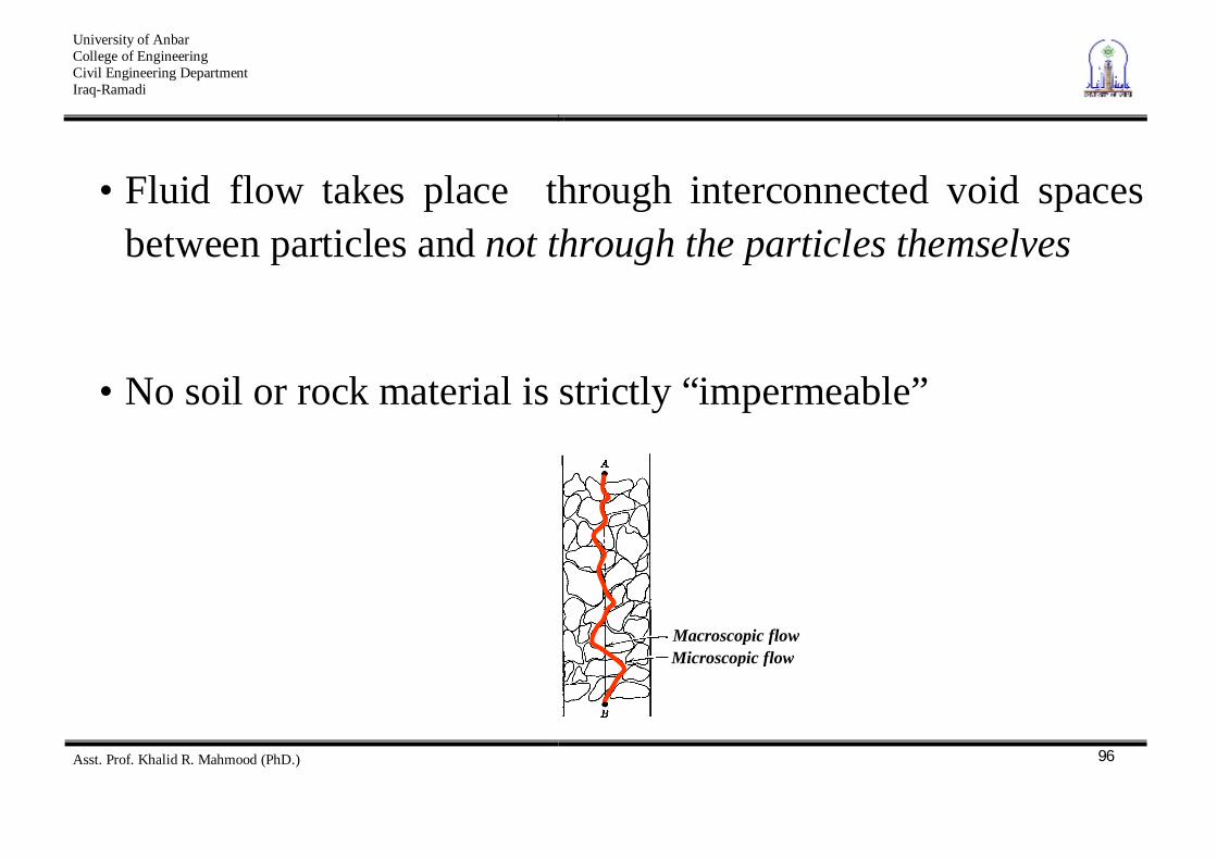
• Fluid flow takes place through interconnected void spaces between particles and not through the particles themselves
• No soil or rock material is strictly “impermeable”
Macroscopic flow Microscopic flow
University of Anbar College of Engineering Civil Engineering Department Iraq-Ramadi
Asst. Prof. Khalid R. Mahmood (PhD.)
97
The study of flow of water through porous media is necessary for-
Estimation Seepage Loss Estimation Pore Water Pressures Evaluation Quicksand Conditions Dewatering System Design Drainage System Design
University of Anbar College of Engineering Civil Engineering Department Iraq-Ramadi
Asst. Prof. Khalid R. Mahmood (PhD.)
98
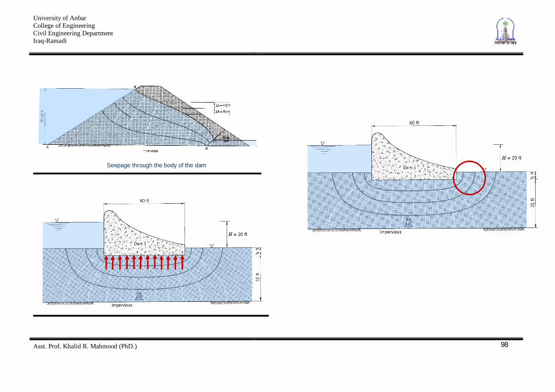
Seepage through the body of the dam
University of Anbar College of Engineering Civil Engineering Department Iraq-Ramadi
Asst. Prof. Khalid R. Mahmood (PhD.)
99
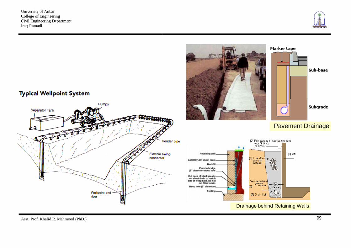
Pavement Drainage
Drainage behind Retaining Walls
University of Anbar College of Engineering Civil Engineering Department Iraq-Ramadi
Asst. Prof. Khalid R. Mahmood (PhD.)
100
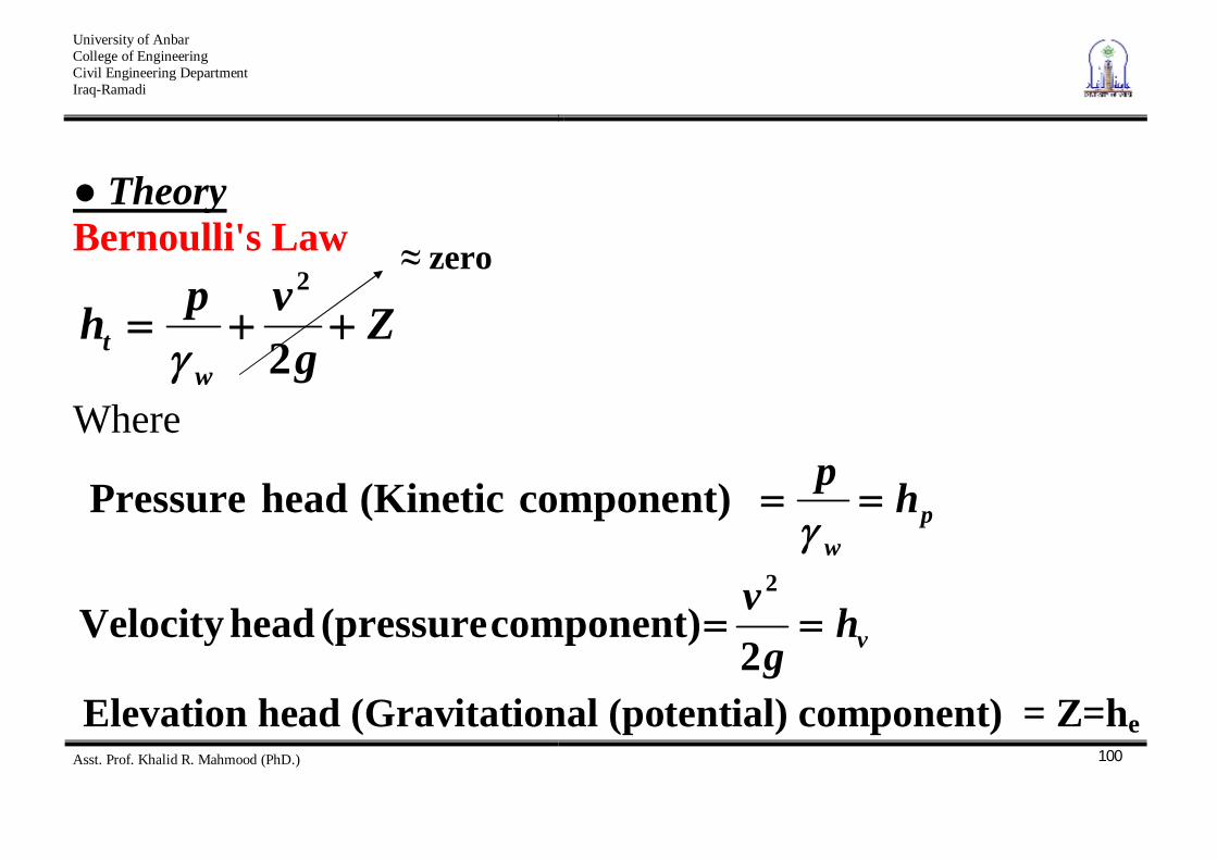
Theory Bernoulli's Law
Zg
vphw
t 2
2
Where
pw
hp component) (Kinetic head Pressure
vhg
v2
component) (pressure head Velocity2
Elevation head (Gravitational (potential) component) = Z=he
zero
University of Anbar College of Engineering Civil Engineering Department Iraq-Ramadi
Asst. Prof. Khalid R. Mahmood (PhD.)
101
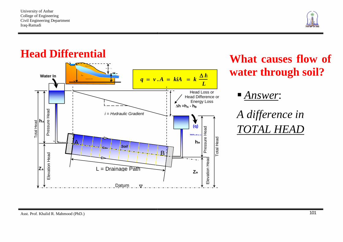
Head Differential
W.T.
Head Loss or Head Difference or
Energy Loss
A B
Soil
Water In
h =hA - hB
hA
hB
i = Hydraulic Gradient
(q)
Water
L = Drainage Path
Datum
hA
W.T.
hB
h = hA - hB
Impervious Soil
Impervious Soil
ZA
Datum
ZB
Elev
atio
n H
ead
Pres
sure
Hea
d
Pres
sure
Hea
d El
evat
ion
Hea
d Tota
l Hea
d Tota
l Hea
d
LhkkiAAvq .
What causes flow of water through soil?
Answer:
A difference in TOTAL HEAD
University of Anbar College of Engineering Civil Engineering Department Iraq-Ramadi
Asst. Prof. Khalid R. Mahmood (PhD.)
102
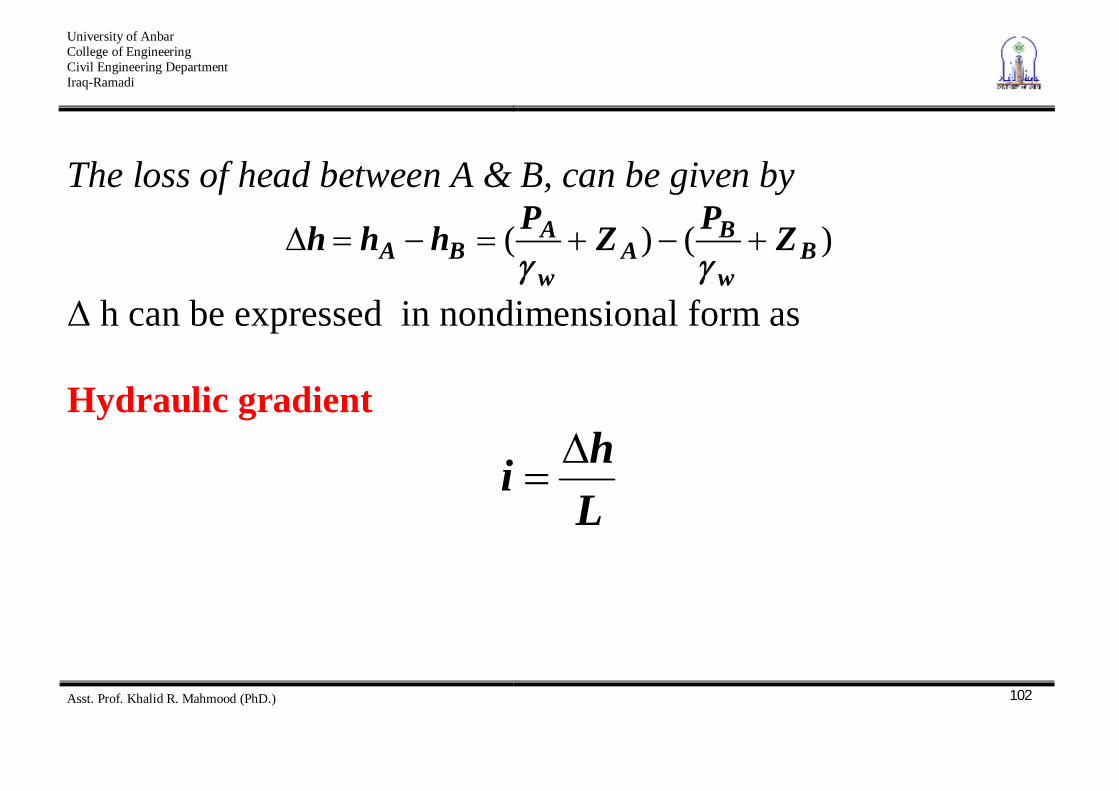
The loss of head between A & B, can be given by
)()( Bw
BA
w
ABA ZPZPhhh
h can be expressed in nondimensional form as Hydraulic gradient
Lhi
University of Anbar College of Engineering Civil Engineering Department Iraq-Ramadi
Asst. Prof. Khalid R. Mahmood (PhD.)
103
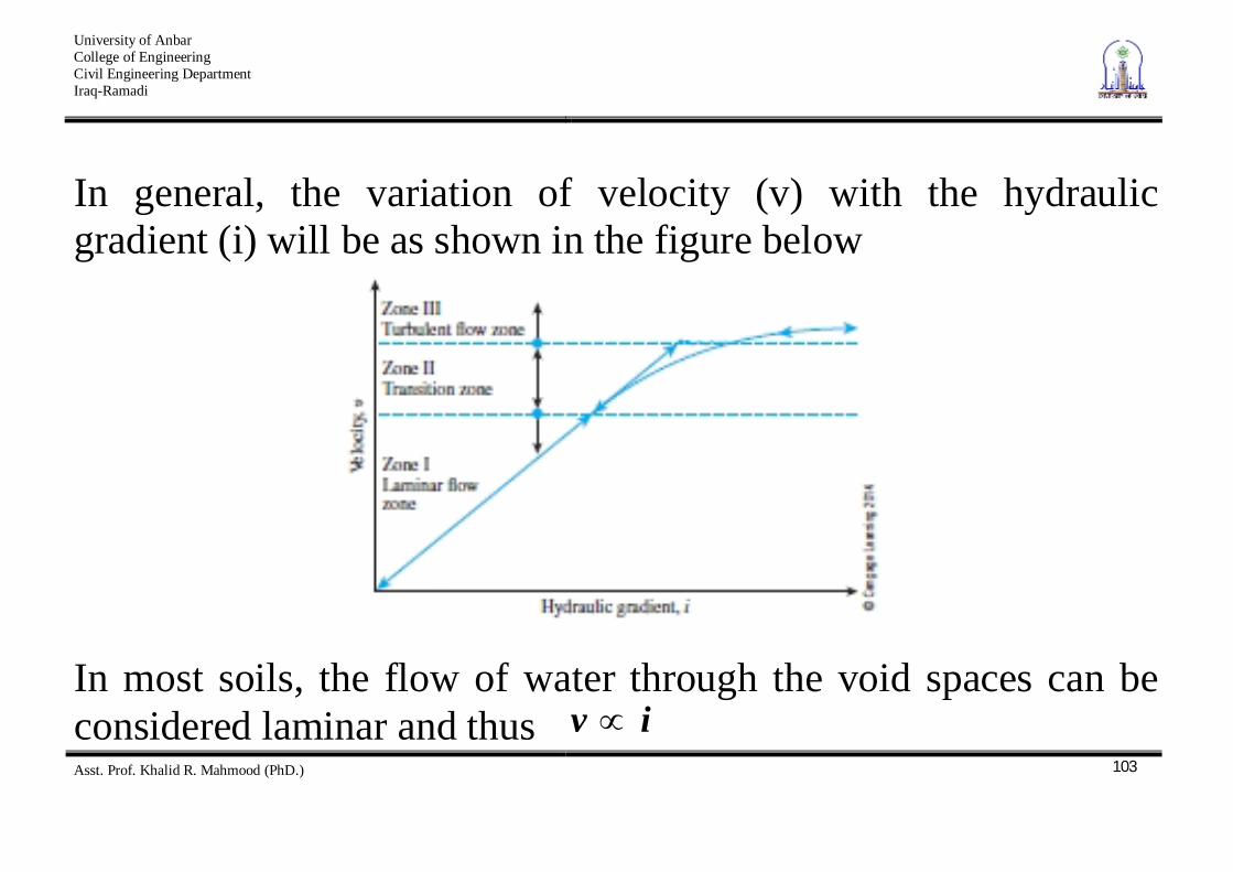
In general, the variation of velocity (v) with the hydraulic gradient (i) will be as shown in the figure below
In most soils, the flow of water through the void spaces can be considered laminar and thus iv
University of Anbar College of Engineering Civil Engineering Department Iraq-Ramadi
Asst. Prof. Khalid R. Mahmood (PhD.)
104
Darcy’s Law In 1856, Darcy published a simple equation for discharge velocity of water through saturated soils, which may expressed as
kiv Where v = discharge velocity = quantity of water flowing in unit time through a unit gross – sectional area of soil at right angles to the direction of flow k = coefficient of permeability
University of Anbar College of Engineering Civil Engineering Department Iraq-Ramadi
Asst. Prof. Khalid R. Mahmood (PhD.)
105
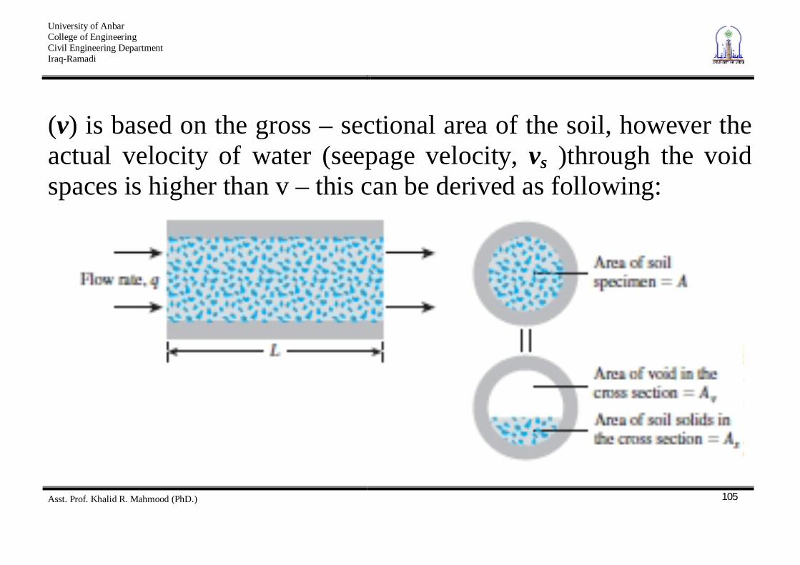
(v) is based on the gross – sectional area of the soil, however the actual velocity of water (seepage velocity, vs )through the void spaces is higher than v – this can be derived as following:
University of Anbar College of Engineering Civil Engineering Department Iraq-Ramadi
Asst. Prof. Khalid R. Mahmood (PhD.)
106
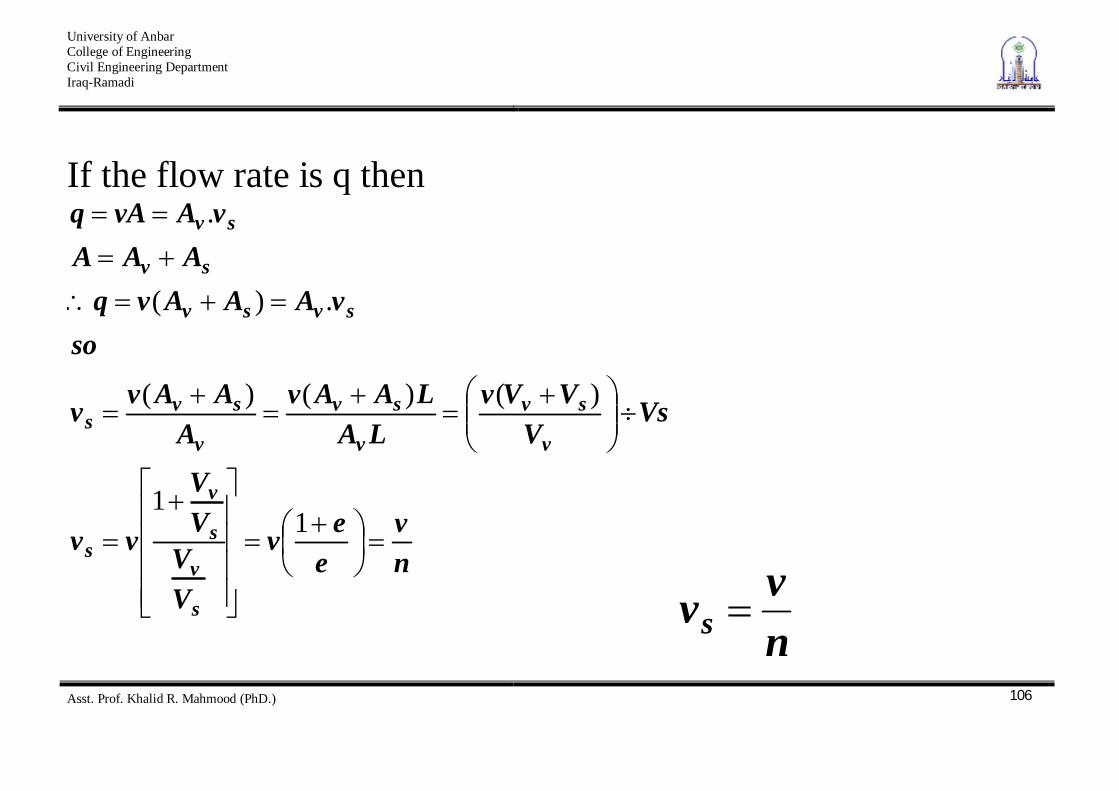
If the flow rate is q then
nv
eev
VV
VV
vv
VsV
VVvLA
LAAvA
AAvv
sovAAAvq
AAAvAvAq
s
v
s
v
s
v
sv
v
sv
v
svs
svsv
sv
sv
11
)()()(
.)(
.
nvvs
University of Anbar College of Engineering Civil Engineering Department Iraq-Ramadi
Asst. Prof. Khalid R. Mahmood (PhD.)
107
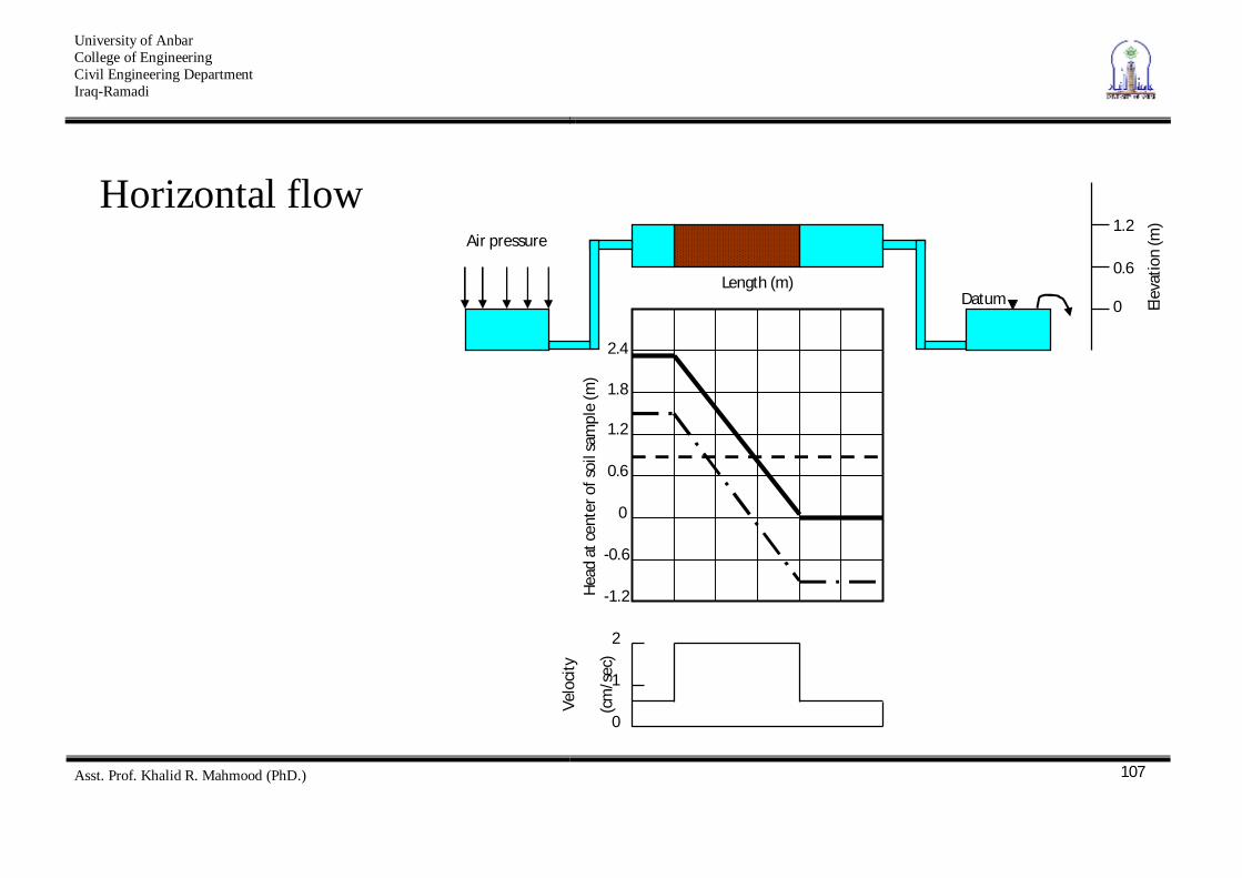
Horizontal flow
Air pressure 1.2
0.6
0 Elev
atio
n (m
)
Length (m)
2.4
1.8
1.2
0.6
0
-0.6
-1.2 Head
at c
ente
r of s
oil s
ampl
e (m
)
2
1
0
Velo
city
(cm
/sec
)
Datum
University of Anbar College of Engineering Civil Engineering Department Iraq-Ramadi
Asst. Prof. Khalid R. Mahmood (PhD.)
108
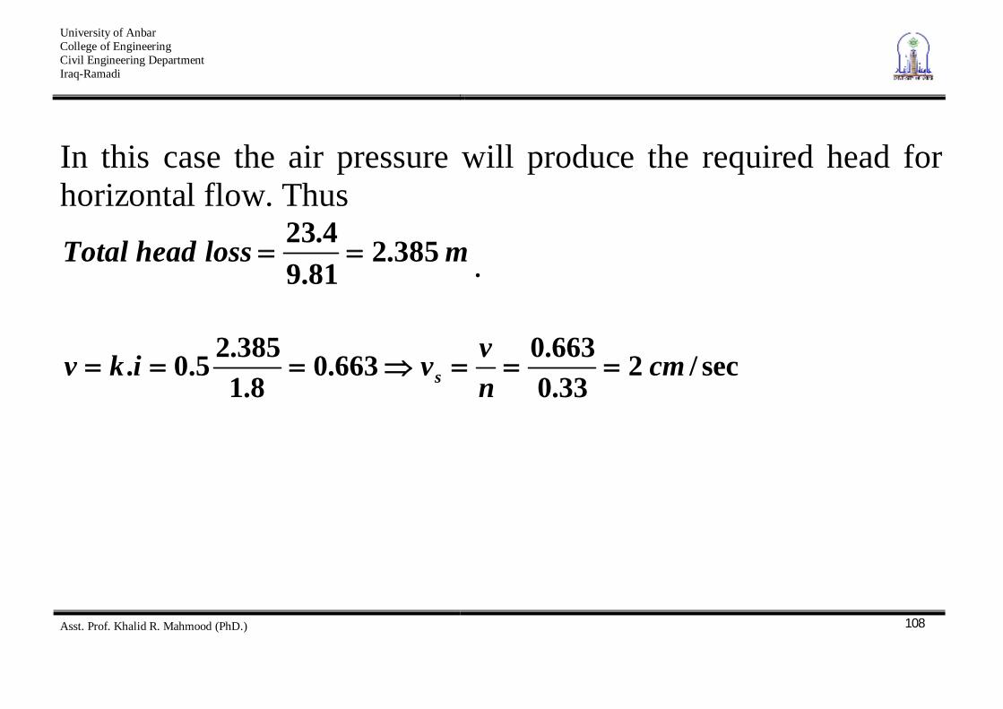
In this case the air pressure will produce the required head for horizontal flow. Thus
mlossheadTotal 385.281.94.23
.
sec/233.0663.0663.0
8.1385.25.0. cm
nvvikv s
University of Anbar College of Engineering Civil Engineering Department Iraq-Ramadi
Asst. Prof. Khalid R. Mahmood (PhD.)
109
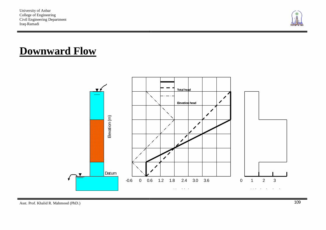
Downward Flow
3.6
3.0
2.4
1.8
1.2
0.6
Elev
atio
n (m
)
-0.6 0 0.6 1.2 1.8 2.4 3.0 3.6
Head (m)
Total head
Elevation head
0 1 2 3
Velocity (cm/sec)
Datum
University of Anbar College of Engineering Civil Engineering Department Iraq-Ramadi
Asst. Prof. Khalid R. Mahmood (PhD.)
110
tube the of partsexit the and entrance theat cm/sec18.16.3.5.0.ikv .
sample soil the through cm/sec333.01
nvvs
University of Anbar College of Engineering Civil Engineering Department Iraq-Ramadi
Asst. Prof. Khalid R. Mahmood (PhD.)
111
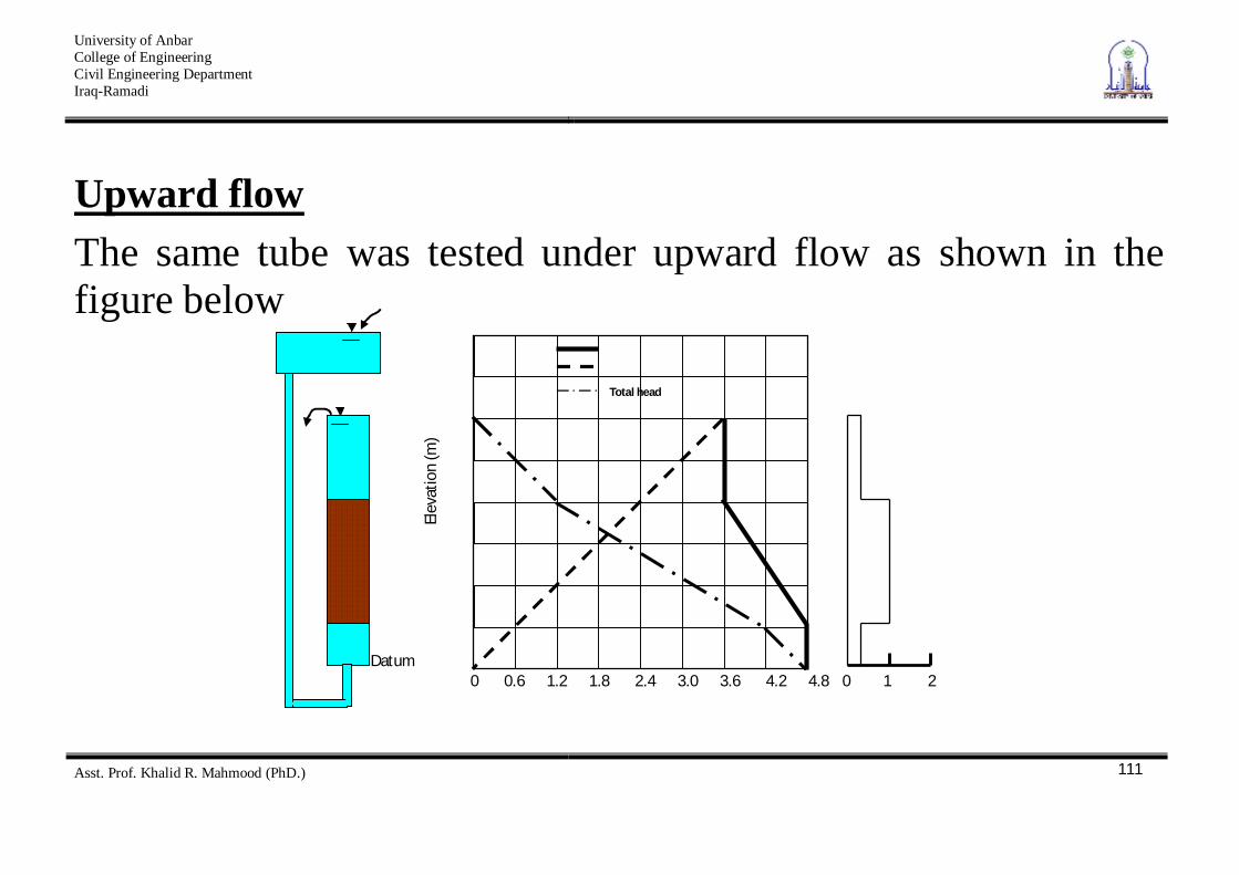
Upward flow The same tube was tested under upward flow as shown in the figure below
0 1 2 0 0.6 1.2 1.8 2.4 3.0 3.6 4.2 4.8
Datum
Elev
atio
n (m
)
Total head
University of Anbar College of Engineering Civil Engineering Department Iraq-Ramadi
Asst. Prof. Khalid R. Mahmood (PhD.)
112
cm/sec133.033.033.0
8.12.1.5.0.
nvvikv s
Hydraulic Conductivity or Coefficient of permeability (k)
It is defined as the rate of flow per unit area of soil under unit hydraulic gradient, it has the dimensions of velocity (L/T) such (cm/sec or ft/sec).
University of Anbar College of Engineering Civil Engineering Department Iraq-Ramadi
Asst. Prof. Khalid R. Mahmood (PhD.)
113
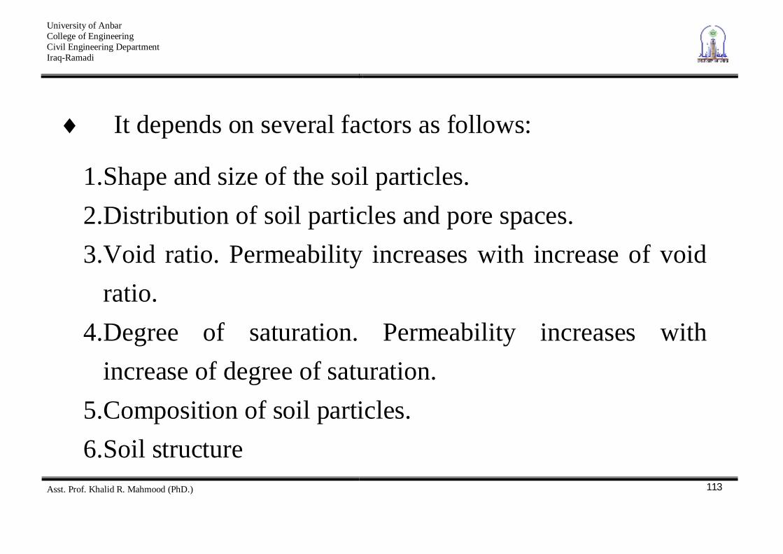
It depends on several factors as follows:
1. Shape and size of the soil particles. 2. Distribution of soil particles and pore spaces. 3. Void ratio. Permeability increases with increase of void
ratio. 4. Degree of saturation. Permeability increases with
increase of degree of saturation. 5. Composition of soil particles. 6. Soil structure
University of Anbar College of Engineering Civil Engineering Department Iraq-Ramadi
Asst. Prof. Khalid R. Mahmood (PhD.)
114
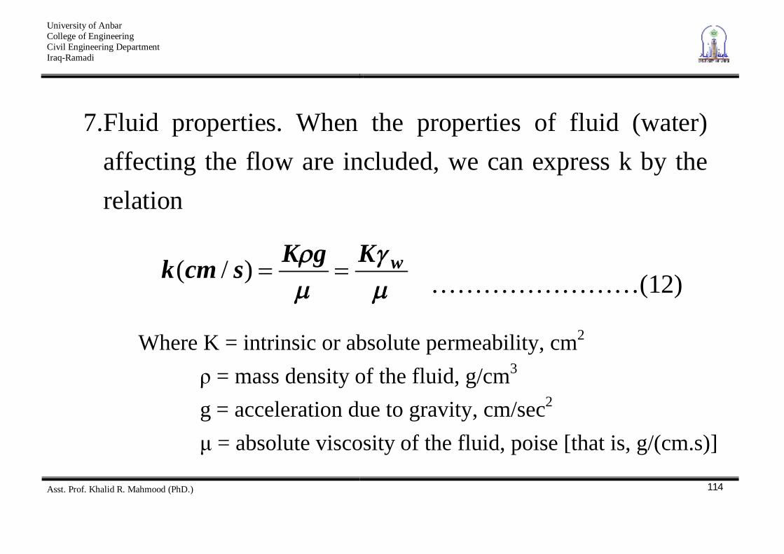
7. Fluid properties. When the properties of fluid (water) affecting the flow are included, we can express k by the relation
wKgKscmk )/( ……………………(12)
Where K = intrinsic or absolute permeability, cm2 = mass density of the fluid, g/cm3 g = acceleration due to gravity, cm/sec2 = absolute viscosity of the fluid, poise [that is, g/(cm.s)]
University of Anbar College of Engineering Civil Engineering Department Iraq-Ramadi
Asst. Prof. Khalid R. Mahmood (PhD.)
115
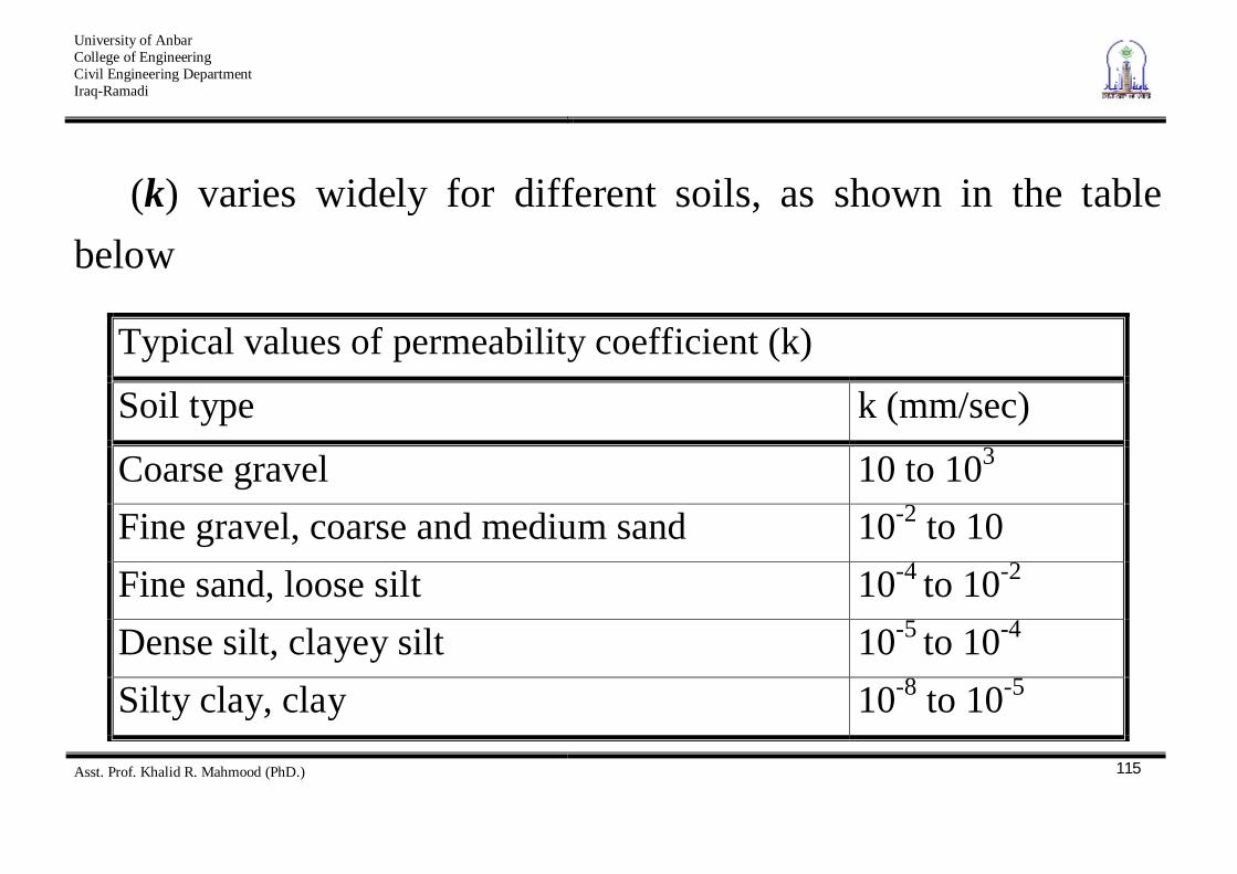
(k) varies widely for different soils, as shown in the table below
Typical values of permeability coefficient (k)
Soil type k (mm/sec)
Coarse gravel 10 to 103 Fine gravel, coarse and medium sand 10-2 to 10 Fine sand, loose silt 10-4 to 10-2
Dense silt, clayey silt 10-5 to 10-4 Silty clay, clay 10-8 to 10-5
University of Anbar College of Engineering Civil Engineering Department Iraq-Ramadi
Asst. Prof. Khalid R. Mahmood (PhD.)
116
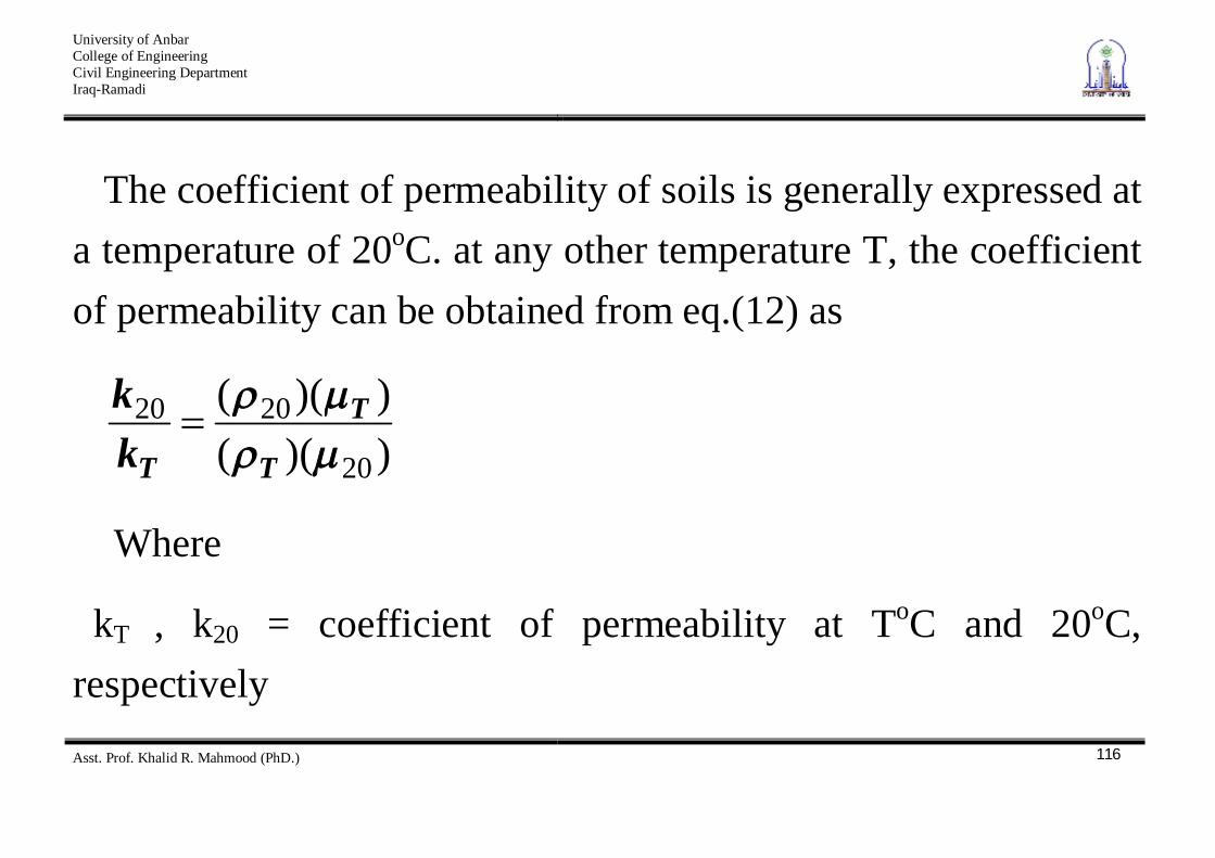
The coefficient of permeability of soils is generally expressed at a temperature of 20oC. at any other temperature T, the coefficient of permeability can be obtained from eq.(12) as
))(())((
20
2020
T
T
Tkk
Where
kT , k20 = coefficient of permeability at ToC and 20oC, respectively
University of Anbar College of Engineering Civil Engineering Department Iraq-Ramadi
Asst. Prof. Khalid R. Mahmood (PhD.)
117
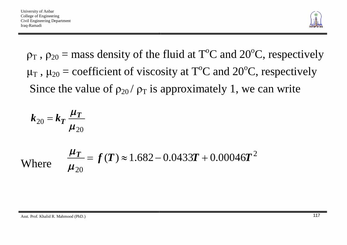
T , 20 = mass density of the fluid at ToC and 20oC, respectively T , 20 = coefficient of viscosity at ToC and 20oC, respectively
Since the value of 20 / T is approximately 1, we can write
2020
TTkk
Where 2
2000046.00433.0682.1)( TTTfT
University of Anbar College of Engineering Civil Engineering Department Iraq-Ramadi
Asst. Prof. Khalid R. Mahmood (PhD.)
118
Laboratory and Field Tests
The four most common laboratory methods for determining the permeability coefficient of soils are the following:
1. Constant – head test. 2. Falling – head test. 3. Indirect determination from consolidation test 4. Indirect determination by horizontal capillary test.
University of Anbar College of Engineering Civil Engineering Department Iraq-Ramadi
Asst. Prof. Khalid R. Mahmood (PhD.)
119
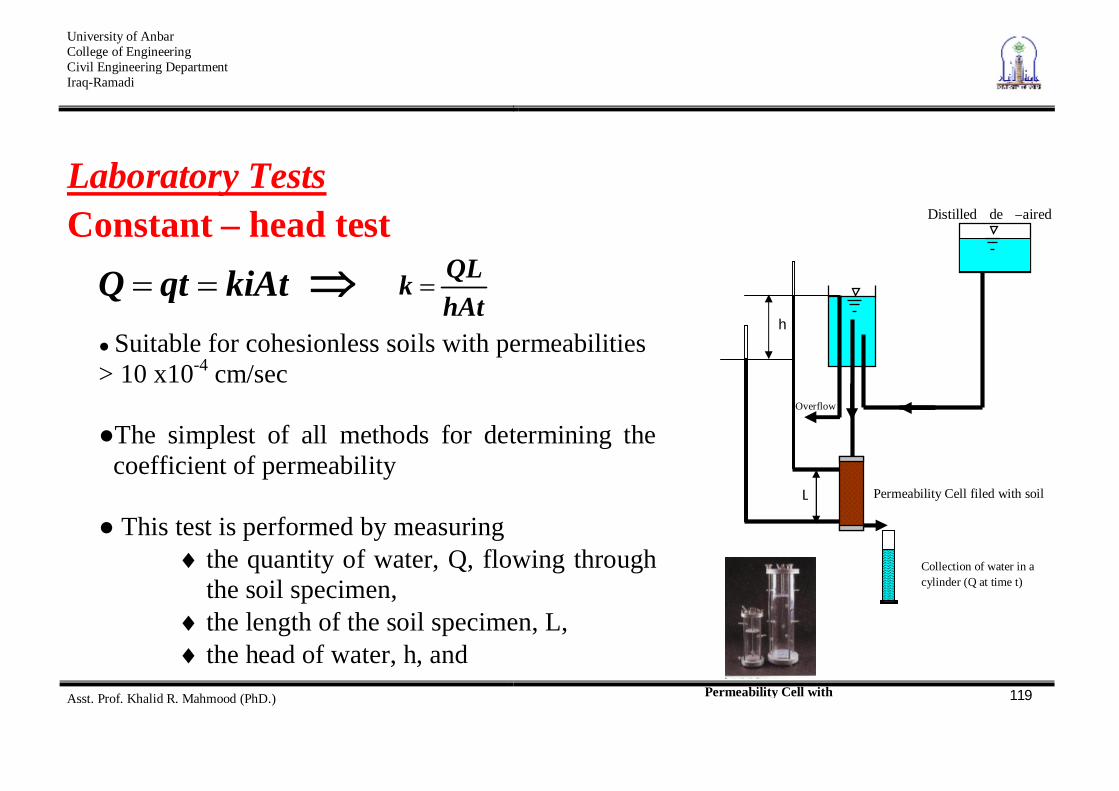
Laboratory Tests Constant – head test
kiAtqtQ hAtQLk
Permeability Cell with
Distilled de –aired
Overflow
h
L
Collection of water in a cylinder (Q at time t)
Permeability Cell filed with soil
Suitable for cohesionless soils with permeabilities
> 10 x10-4 cm/sec
The simplest of all methods for determining the coefficient of permeability
This test is performed by measuring
the quantity of water, Q, flowing through the soil specimen, the length of the soil specimen, L, the head of water, h, and the elapsed time, t.
University of Anbar College of Engineering Civil Engineering Department Iraq-Ramadi
Asst. Prof. Khalid R. Mahmood (PhD.)
120
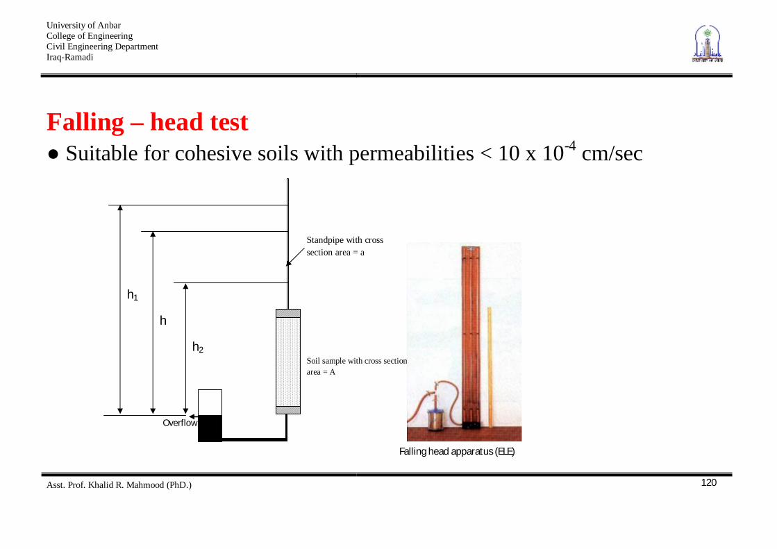
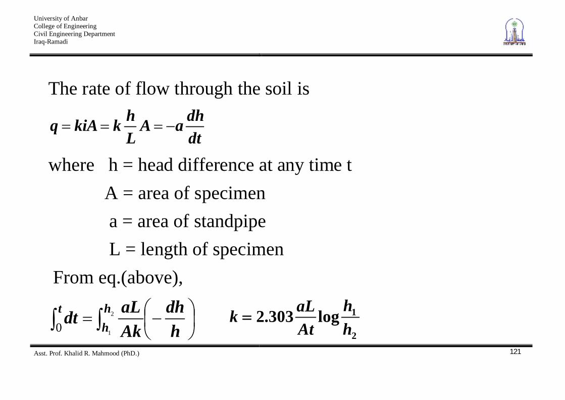
Falling – head test Suitable for cohesive soils with permeabilities < 10 x 10-4 cm/sec
Standpipe with cross section area = a
Soil sample with cross section area = A
h2
h
h1
Overflow
Falling head apparatus (ELE)
University of Anbar College of Engineering Civil Engineering Department Iraq-Ramadi
Asst. Prof. Khalid R. Mahmood (PhD.)
121
The rate of flow through the soil is
dtdhaA
LhkkiAq
where h = head difference at any time t A = area of specimen a = area of standpipe L = length of specimen From eq.(above),
hdh
AkaLdt h
ht 2
10 2
1log303.2hh
AtaLk
University of Anbar College of Engineering Civil Engineering Department Iraq-Ramadi
Asst. Prof. Khalid R. Mahmood (PhD.)
122
Field tests There are many useful methods to determine the permeability coefficient in field such as
1. pumping from wells 2. Bore hole test 3. Open – end test 4. Packer test 5. Variable – head tests by means of piezometer observation
well
University of Anbar College of Engineering Civil Engineering Department Iraq-Ramadi
Asst. Prof. Khalid R. Mahmood (PhD.)
123
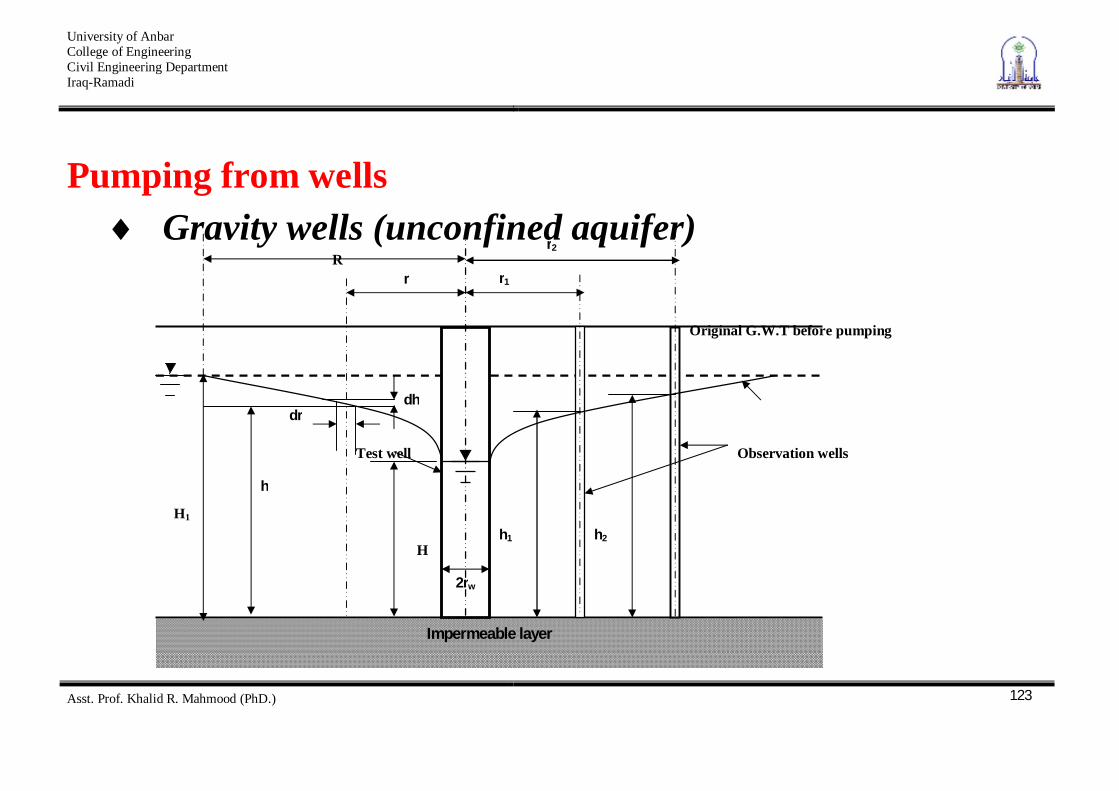
Pumping from wells Gravity wells (unconfined aquifer)
Original G.W.T before pumping
Impermeable layer
dr dh
r1
r2 R
r
Observation wells Test well
h
2rw
h1 h2 H
H1
University of Anbar College of Engineering Civil Engineering Department Iraq-Ramadi
Asst. Prof. Khalid R. Mahmood (PhD.)
124
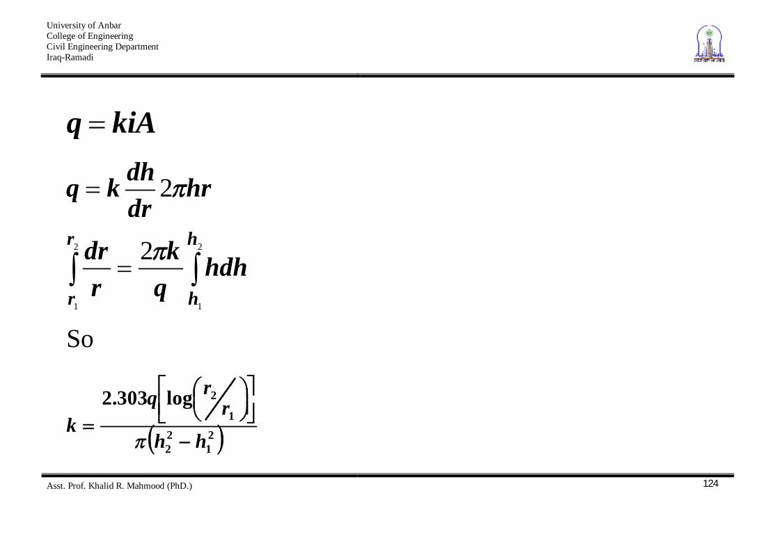
kiAq
2
1
2
1
2
2
h
h
r
rhdh
qk
rdr
hrdrdhkq
So
21
22
1
2log303.2
hhr
rqk
University of Anbar College of Engineering Civil Engineering Department Iraq-Ramadi
Asst. Prof. Khalid R. Mahmood (PhD.)
125
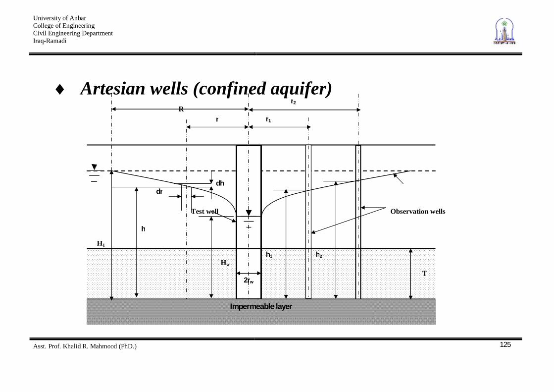
Artesian wells (confined aquifer)
Impermeable layer
dr dh
r1
r2 R
r
Observation wells Test well
h
2rw
h1 h2 Hw
H1
T
University of Anbar College of Engineering Civil Engineering Department Iraq-Ramadi
Asst. Prof. Khalid R. Mahmood (PhD.)
126
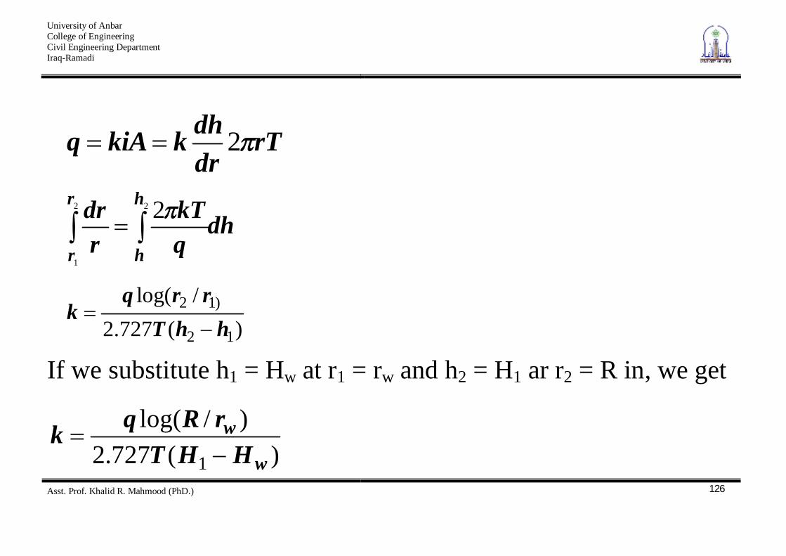
rTdrdhkkiAq 2
dhqkT
rdr h
h
r
r
22
1
2
)(727.2/log(
12
)12
hhTrrq
k
If we substitute h1 = Hw at r1 = rw and h2 = H1 ar r2 = R in, we get
)(727.2)/log(
1 w
wHHT
rRqk
University of Anbar College of Engineering Civil Engineering Department Iraq-Ramadi
Asst. Prof. Khalid R. Mahmood (PhD.)
127
Empirical Correlations Several empirical equations for estimation of the permeability coefficient have been proposed in the past.
University of Anbar College of Engineering Civil Engineering Department Iraq-Ramadi
Asst. Prof. Khalid R. Mahmood (PhD.)
128
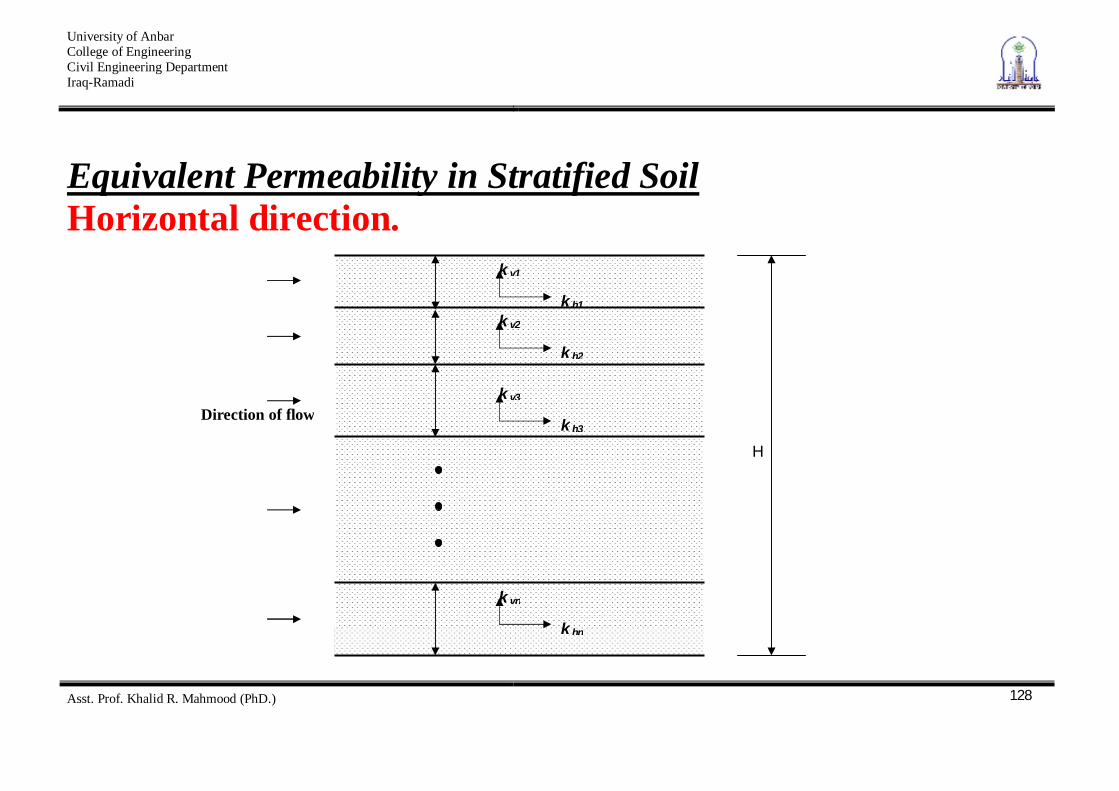
Equivalent Permeability in Stratified Soil Horizontal direction.
k h1
k v1
k h2
k v2
k h3
k v3
k hn
k vn
Direction of flow
H
University of Anbar College of Engineering Civil Engineering Department Iraq-Ramadi
Asst. Prof. Khalid R. Mahmood (PhD.)
129
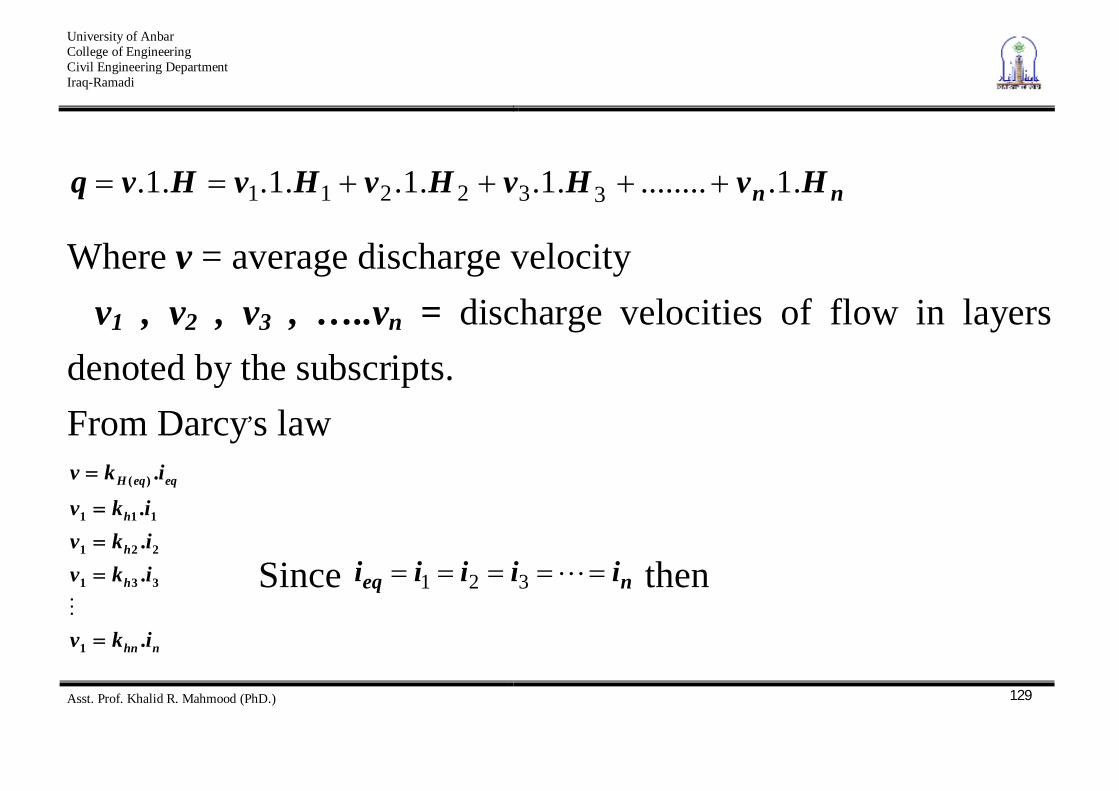
nn HvHvHvHvHvq .1..........1..1..1..1. 332211
Where v = average discharge velocity v1 , v2 , v3 , …..vn = discharge velocities of flow in layers denoted by the subscripts. From Darcy,s law
nhn
h
h
h
eqeqH
ikv
ikvikvikv
ikv
.
.
.
.
.
1
331
221
111
)(
Since neq iiiii 321 then
University of Anbar College of Engineering Civil Engineering Department Iraq-Ramadi
Asst. Prof. Khalid R. Mahmood (PhD.)
130
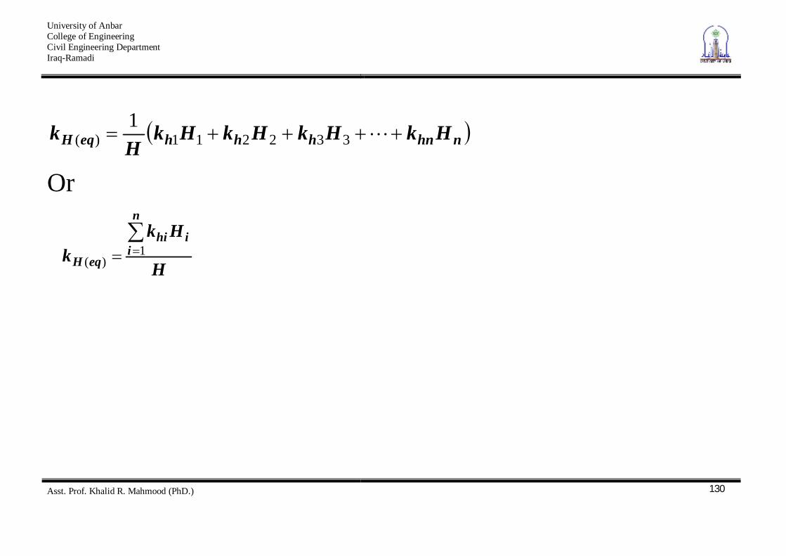
nhnhhheqH HkHkHkHkH
k 332211)(1
Or
H
Hkk
n
iihi
eqH1
)(
University of Anbar College of Engineering Civil Engineering Department Iraq-Ramadi
Asst. Prof. Khalid R. Mahmood (PhD.)
131
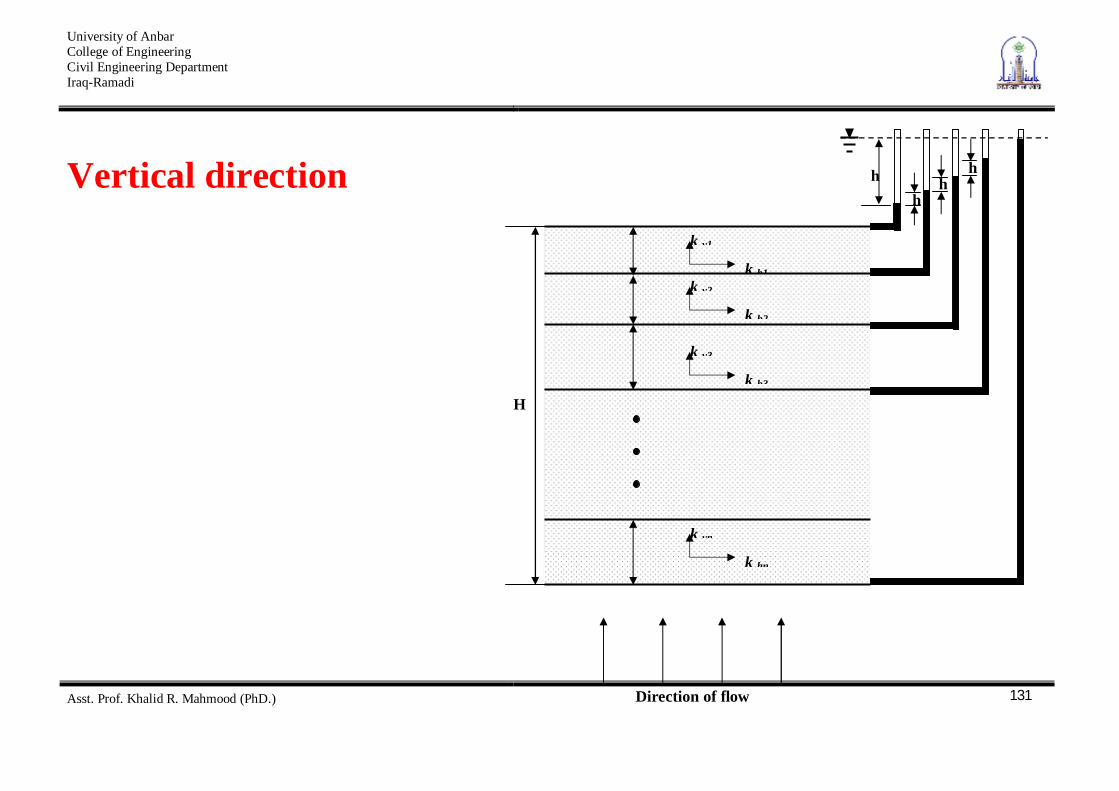
Vertical direction
k h1
k v1
k h2
k v2
k h3
k v3
k hn
k vn
Direction of flow
H
h h
h
h
University of Anbar College of Engineering Civil Engineering Department Iraq-Ramadi
Asst. Prof. Khalid R. Mahmood (PhD.)
132
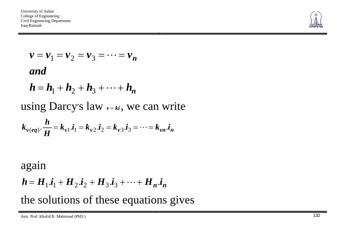
n
n
hhhhhand
vvvvv
321
321
using Darcy,s law kiv , we can write
nvnvvveqv ikikikikHhk ..... 332211)(
again
nn iHiHiHiHh .... 332211 the solutions of these equations gives
University of Anbar College of Engineering Civil Engineering Department Iraq-Ramadi
Asst. Prof. Khalid R. Mahmood (PhD.)
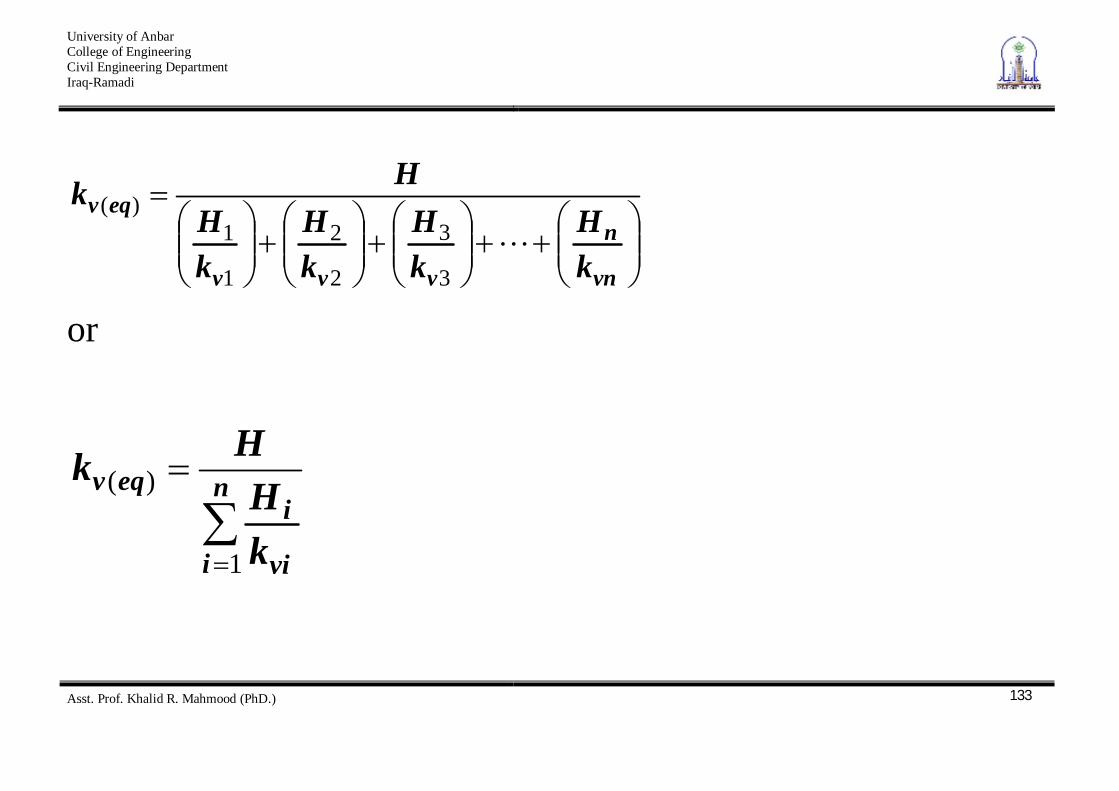
133
vn
n
vvv
eqv
kH
kH
kH
kH
Hk
3
3
2
2
1
1)(
or
n
i vi
ieqv
kH
Hk
1
)(
University of Anbar College of Engineering Civil Engineering Department Iraq-Ramadi
Asst. Prof. Khalid R. Mahmood (PhD.)
134
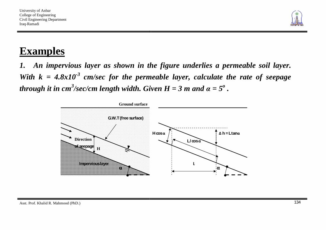
Examples 1. An impervious layer as shown in the figure underlies a permeable soil layer. With k = 4.8x10⁻³ cm/sec for the permeable layer, calculate the rate of seepage through it in cm3/sec/cm length width. Given H = 3 m and = 5o .
Ground surface
G.W.T (free surface)
H
Direction of seepage
Impervious layer
h = L tan H cos
L
L /cos
University of Anbar College of Engineering Civil Engineering Department Iraq-Ramadi
Asst. Prof. Khalid R. Mahmood (PhD.)
135
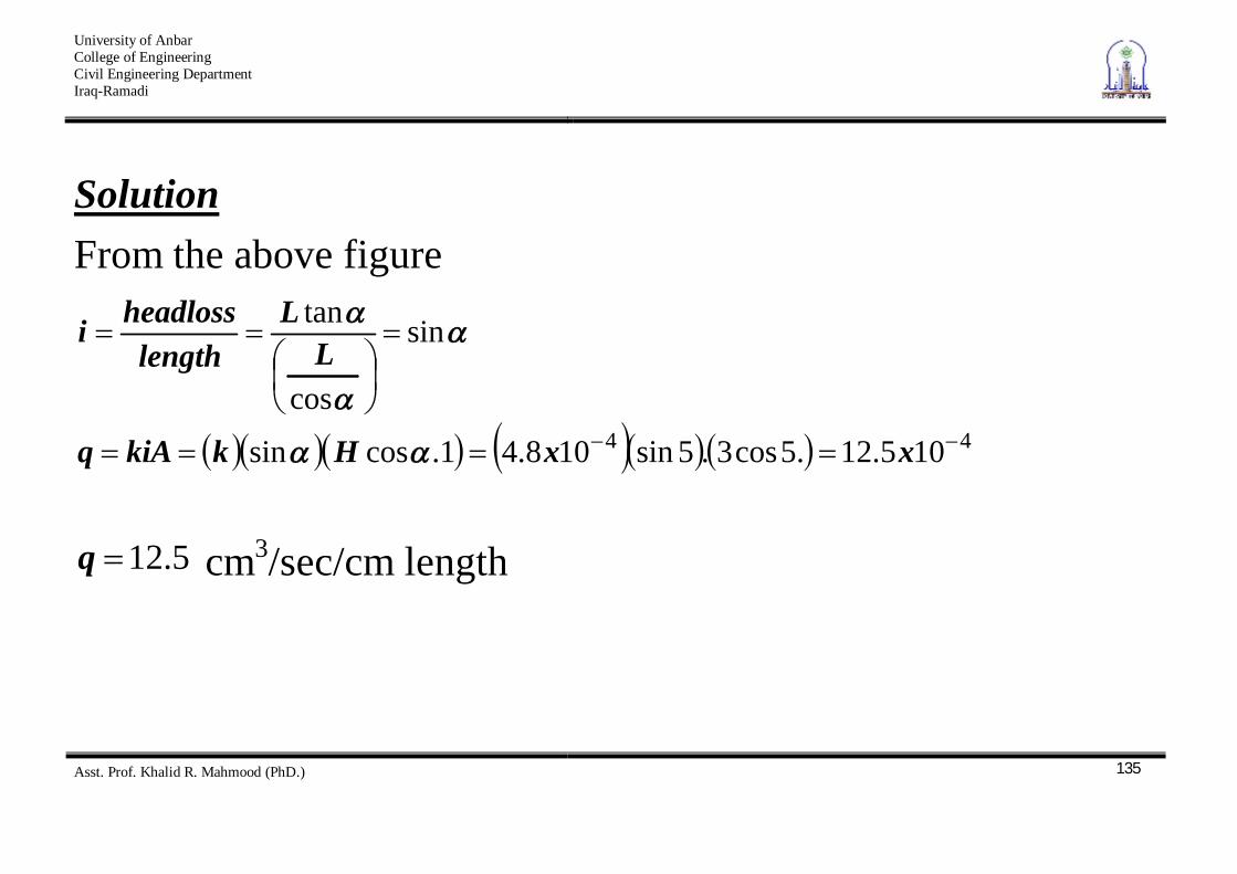
Solution From the above figure
44 105.12.5cos3.5sin108.41.cossin
sin
cos
tan
xxHkkiAq
LL
lengthheadlossi
5.12q cm3/sec/cm length
University of Anbar College of Engineering Civil Engineering Department Iraq-Ramadi
Asst. Prof. Khalid R. Mahmood (PhD.)
136
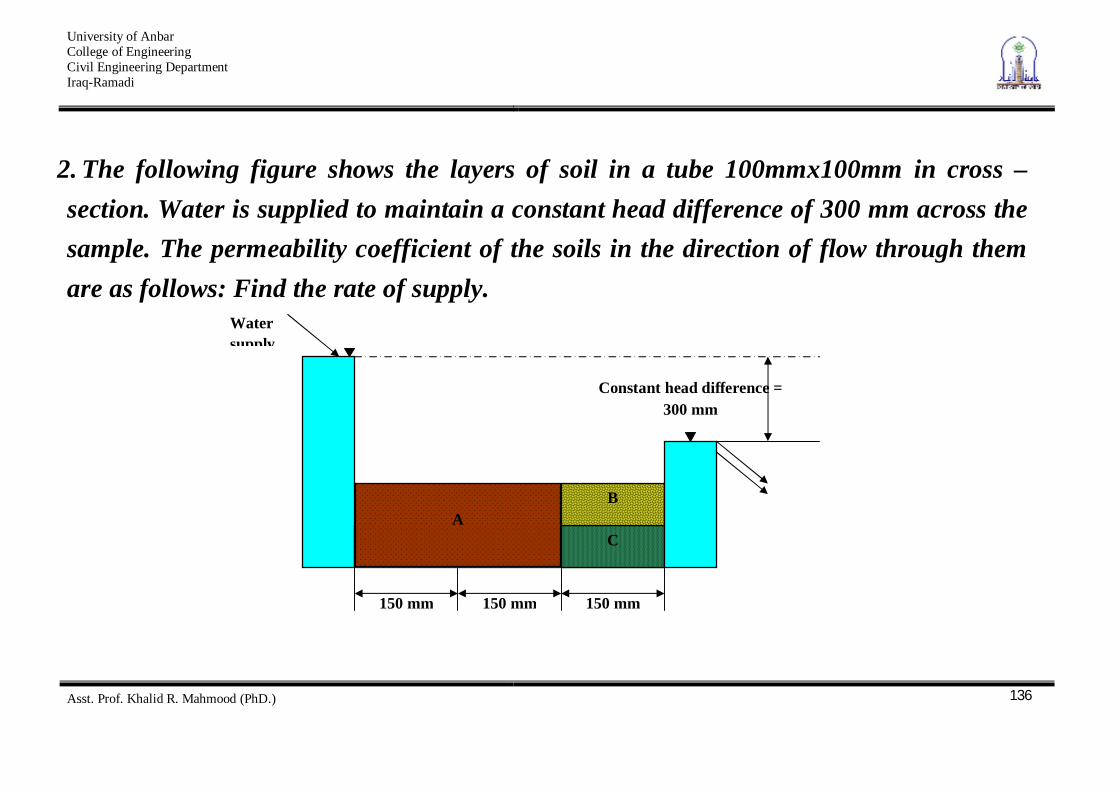
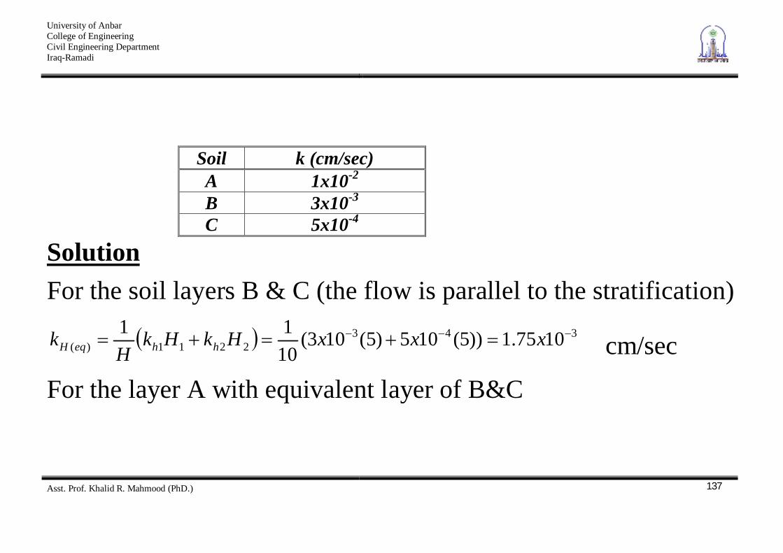
2. The following figure shows the layers of soil in a tube 100mmx100mm in cross – section. Water is supplied to maintain a constant head difference of 300 mm across the sample. The permeability coefficient of the soils in the direction of flow through them are as follows: Find the rate of supply.
A
C
B
Constant head difference = 300 mm
Water supply
150 mm 150 mm 150 mm
University of Anbar College of Engineering Civil Engineering Department Iraq-Ramadi
Asst. Prof. Khalid R. Mahmood (PhD.)
137
Soil k (cm/sec) A 1x10⁻²
B 3x10⁻³ C 5x10⁻⁴
Solution For the soil layers B & C (the flow is parallel to the stratification)
3432211)( 1075.1))5(105)5(103(
1011 xxxHkHk
Hk hheqH cm/sec
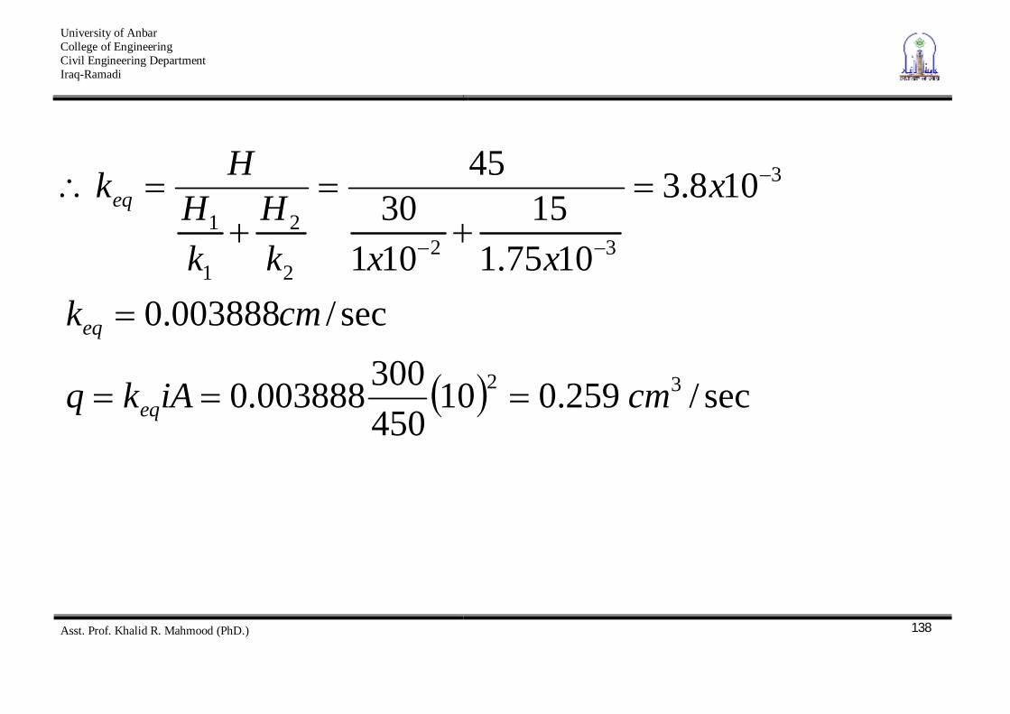
For the layer A with equivalent layer of B&C
University of Anbar College of Engineering Civil Engineering Department Iraq-Ramadi
Asst. Prof. Khalid R. Mahmood (PhD.)
138
sec/259.010450300003888.0
sec/003888.0
108.3
1075.115
10130
45
32
3
322
2
1
1
cmiAkq
cmk
x
xxkH
kH
Hk
eq
eq
eq
University of Anbar College of Engineering Civil Engineering Department Iraq-Ramadi
Asst. Prof. Khalid R. Mahmood (PhD.)
139
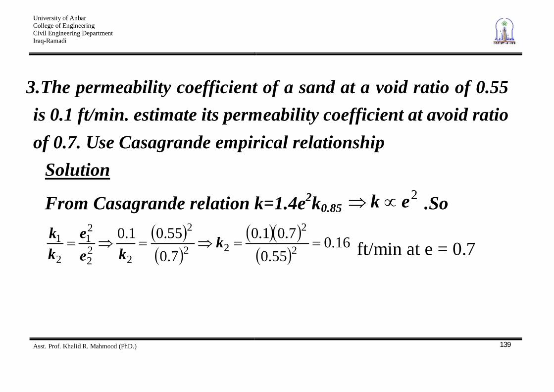
3. The permeability coefficient of a sand at a void ratio of 0.55 is 0.1 ft/min. estimate its permeability coefficient at avoid ratio of 0.7. Use Casagrande empirical relationship
Solution
From Casagrande relation k=1.4e2k0.85 2ek .So
16.055.0
7.01.07.055.01.0
2
2
22
2
222
21
2
1 kke
ekk
ft/min at e = 0.7
University of Anbar College of Engineering Civil Engineering Department Iraq-Ramadi
Asst. Prof. Khalid R. Mahmood (PhD.)
140
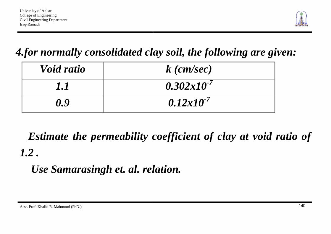
4. for normally consolidated clay soil, the following are given: Void ratio k (cm/sec)
1.1 0.302x10⁻⁷ 0.9 0.12x10⁻⁷
Estimate the permeability coefficient of clay at void ratio of
1.2 . Use Samarasingh et. al. relation.
University of Anbar College of Engineering Civil Engineering Department Iraq-Ramadi
Asst. Prof. Khalid R. Mahmood (PhD.)
141
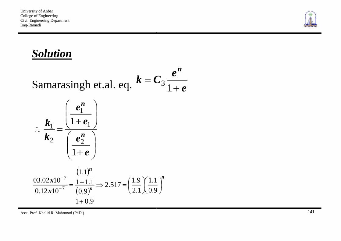
Solution
Samarasingh et.al. eq. eeCk
n
13
e
e
ee
kk
n
n
1
1
2
1
1
2
1
n
n
n
xx
9.01.1
1.29.1517.2
9.019.0
1.111.1
1012.01002.03
7
7
University of Anbar College of Engineering Civil Engineering Department Iraq-Ramadi
Asst. Prof. Khalid R. Mahmood (PhD.)
142
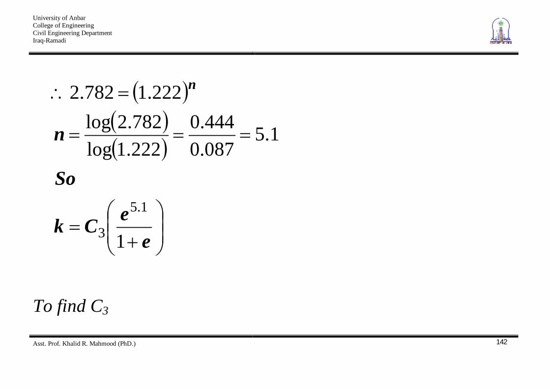
eeCk
So
n
n
1
1.5087.0444.0
222.1log782.2log
222.1782.2
1.5
3
To find C3
University of Anbar College of Engineering Civil Engineering Department Iraq-Ramadi
Asst. Prof. Khalid R. Mahmood (PhD.)
143
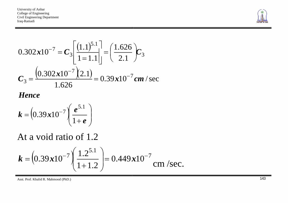
eexk
Hence
cmxxC
CCx
11039.0
sec/1039.0626.1
1.210302.0
1.2626.1
1.111.110302.0
1.57
77
3
3
1.5
37
At a void ratio of 1.2
71.5
7 10449.02.11
2.11039.0 xxk cm /sec.
University of Anbar College of Engineering Civil Engineering Department Iraq-Ramadi
Asst. Prof. Khalid R. Mahmood (PhD.)
144
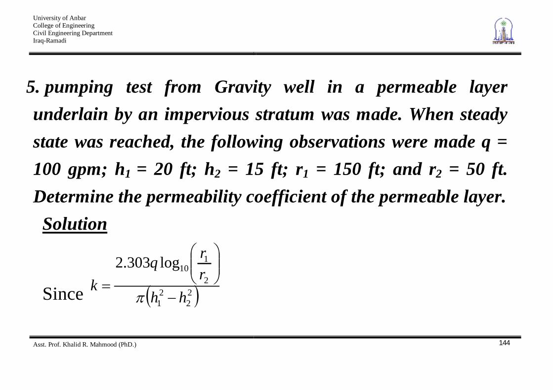
5. pumping test from Gravity well in a permeable layer underlain by an impervious stratum was made. When steady state was reached, the following observations were made q = 100 gpm; h1 = 20 ft; h2 = 15 ft; r1 = 150 ft; and r2 = 50 ft. Determine the permeability coefficient of the permeable layer.
Solution
Since 22
21
2
110log303.2
hhrrq
k
University of Anbar College of Engineering Civil Engineering Department Iraq-Ramadi
Asst. Prof. Khalid R. Mahmood (PhD.)
145
Given: q = 100gpm = 13.37 ft3 / min, so
min/027.0min/0267.01520
50150log37.13303.2
22
10
ftftx
k
University of Anbar College of Engineering Civil Engineering Department Iraq-Ramadi
Asst. Prof. Khalid R. Mahmood (PhD.)
146
Seepage Laplace’s Equation of Continuity
Introduction In many instances, the flow of water through soil is not in one direction only, nor is it uniform over the entire area perpendicular to the flow. In such cases, calculation of ground water flow is generally made by use of graphs referred to as flow nets.
University of Anbar College of Engineering Civil Engineering Department Iraq-Ramadi
Asst. Prof. Khalid R. Mahmood (PhD.)
147
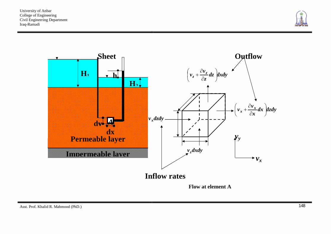
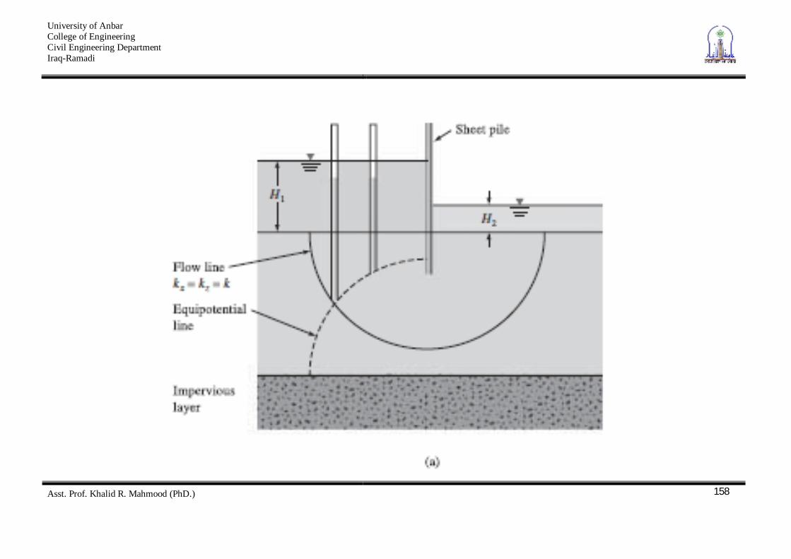
The concept of the flow net is based on Laplace,s equation of continuity, which describes the steady flow condition for a given point in the soil mass. Derivation To derive the Laplace differential equation of continuity, let us take a single row of sheet piles that have been driven into a permeable soil layer, as shown in the figure below.
University of Anbar College of Engineering Civil Engineering Department Iraq-Ramadi
Asst. Prof. Khalid R. Mahmood (PhD.)
148
A
H1
H2
h
Sheet
dx dy
Impermeable layer
Permeable layer dxdyvz
dzdydxxvv x
x
dxdydzzv
v zz
dzdyvx
Flow at element A
Inflow rates
Outflow
vy
vx
University of Anbar College of Engineering Civil Engineering Department Iraq-Ramadi
Asst. Prof. Khalid R. Mahmood (PhD.)
149
Assumptions: 1. The row of sheet piles is impervious 2. The steady state flow of water from the upstream to the
downstream side through the permeable layer is a two – dimensional flow.
3. The water is incompressible 4. No volume change occurs in the soil mass. Thus, the total rate of inflow should be equal to the total rate of outflow
University of Anbar College of Engineering Civil Engineering Department Iraq-Ramadi
Asst. Prof. Khalid R. Mahmood (PhD.)
150
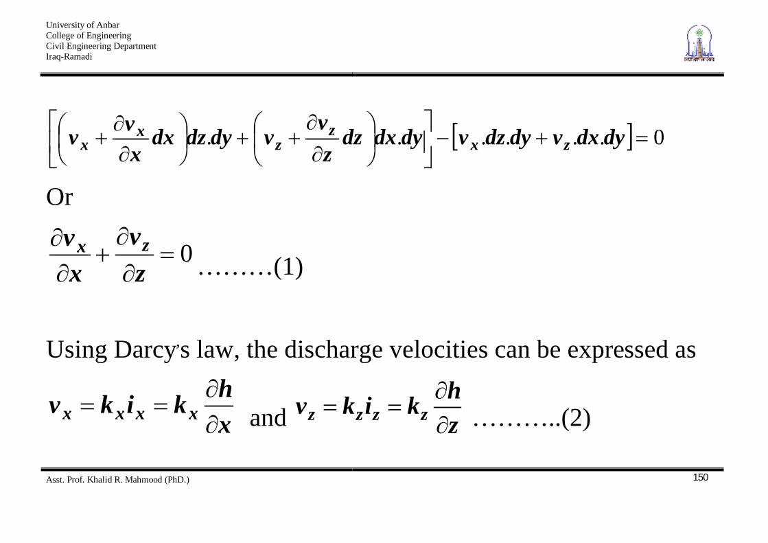
0...... dydxvdydzvdydxdzzv
vdydzdxxvv zx
zz
xx
Or
0zv
xv zx
………(1)
Using Darcy,s law, the discharge velocities can be expressed as
xhkikv xxxx and z
hkikv zzzz ………..(2)
University of Anbar College of Engineering Civil Engineering Department Iraq-Ramadi
Asst. Prof. Khalid R. Mahmood (PhD.)
151
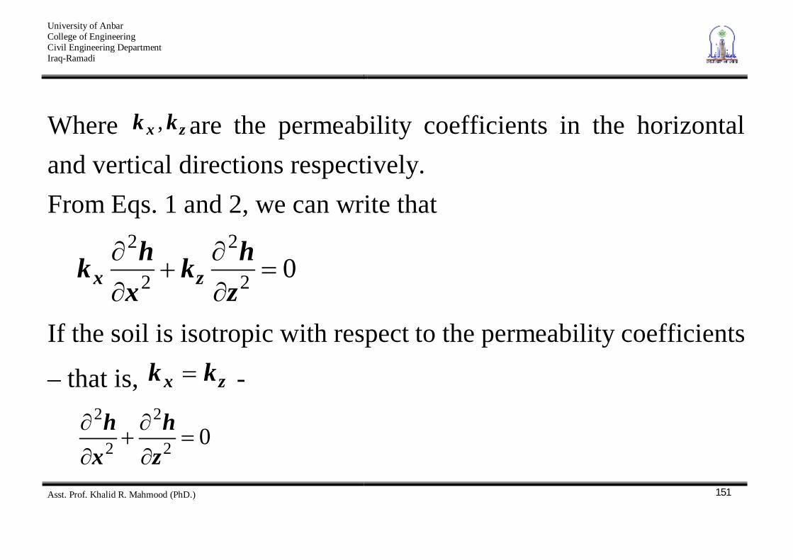
Where zx kk , are the permeability coefficients in the horizontal and vertical directions respectively. From Eqs. 1 and 2, we can write that
02
2
2
2
zhk
xhk zx
If the soil is isotropic with respect to the permeability coefficients
– that is, zx kk -
02
2
2
2
zh
xh
University of Anbar College of Engineering Civil Engineering Department Iraq-Ramadi
Asst. Prof. Khalid R. Mahmood (PhD.)
152
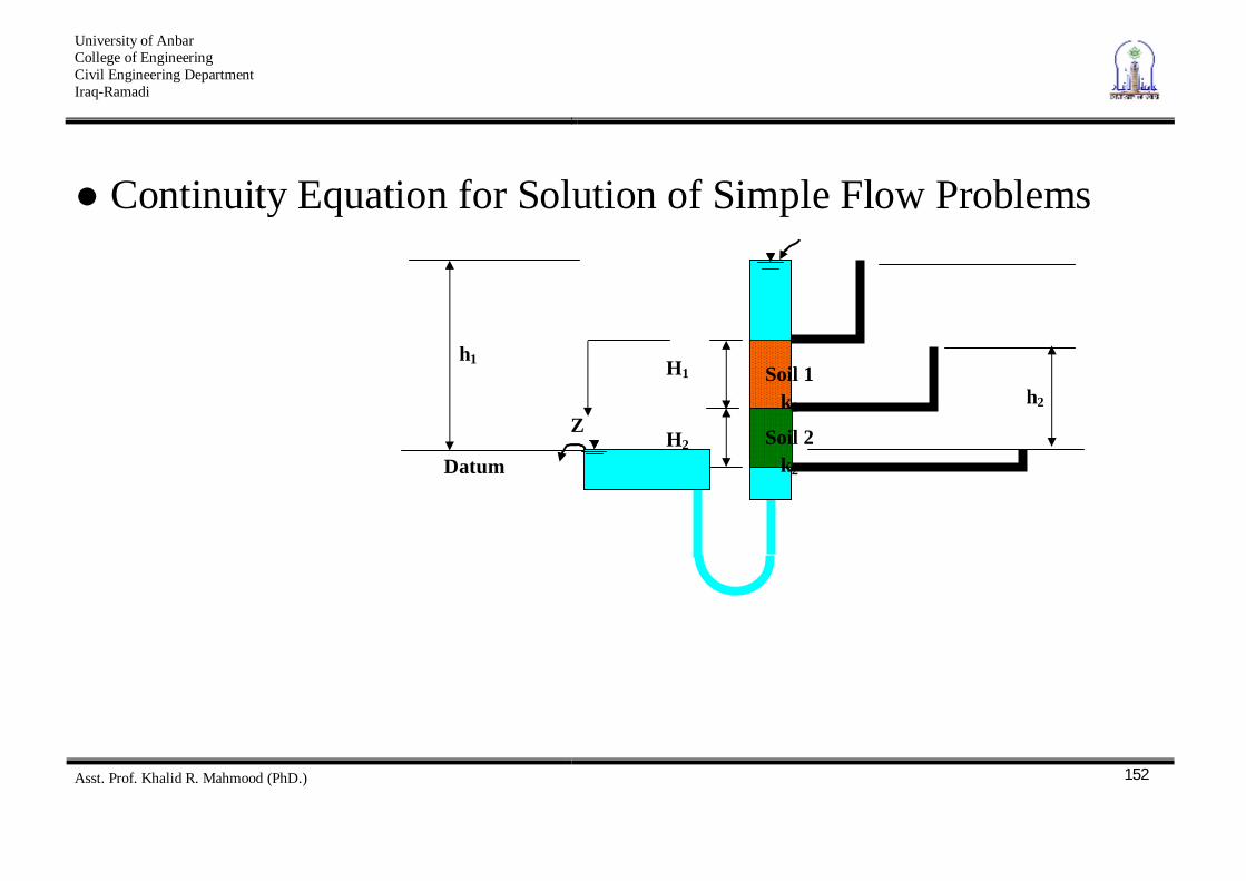
Continuity Equation for Solution of Simple Flow Problems
Soil 1 k1
Soil 2 k2 Datum
Z
h1 H1
H2
h2
University of Anbar College of Engineering Civil Engineering Department Iraq-Ramadi
Asst. Prof. Khalid R. Mahmood (PhD.)
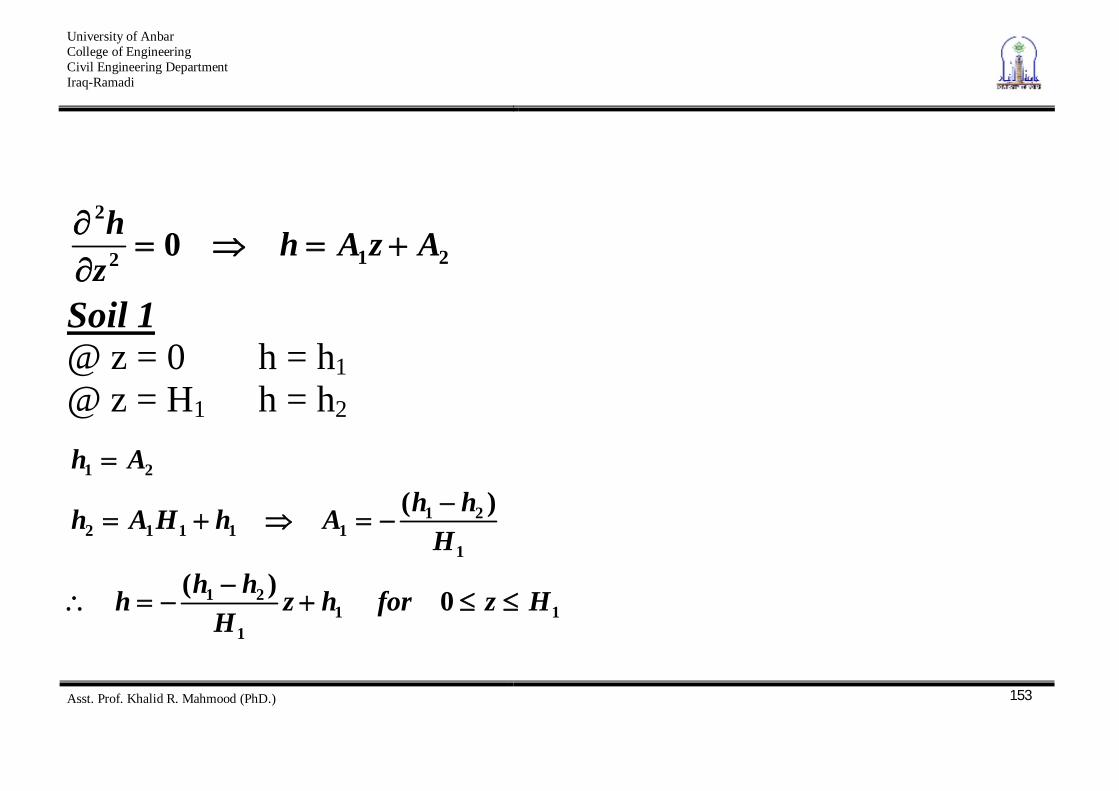
153
212
2
0 AzAhzh
Soil 1 @ z = 0 h = h1 @ z = H1 h = h2
111
21
1
2111112
21
0)(
)(
HzforhzH
hhh
HhhAhHAh
Ah
University of Anbar College of Engineering Civil Engineering Department Iraq-Ramadi
Asst. Prof. Khalid R. Mahmood (PhD.)
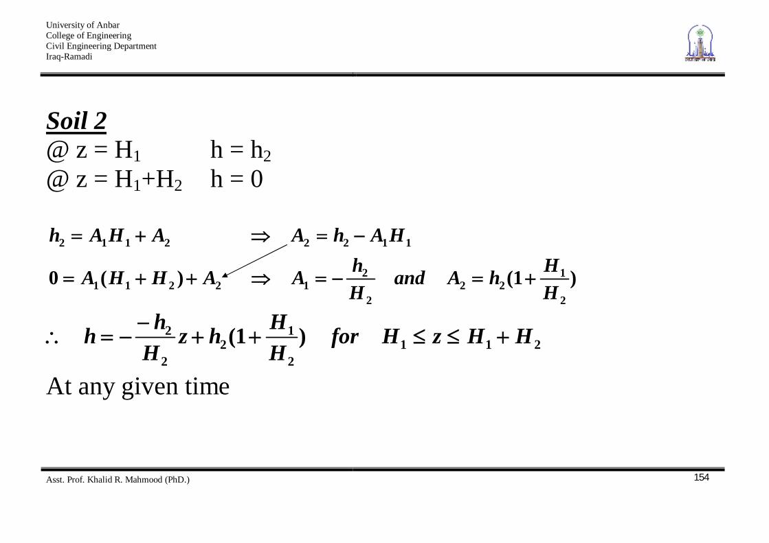
154
Soil 2 @ z = H1 h = h2 @ z = H1+H2 h = 0
)1()(02
122
2
212211
11222112
HHhAand
HhAAHHA
HAhAAHAh
2112
12
2
2 )1( HHzHforHHhz
Hhh
At any given time
University of Anbar College of Engineering Civil Engineering Department Iraq-Ramadi
Asst. Prof. Khalid R. Mahmood (PhD.)
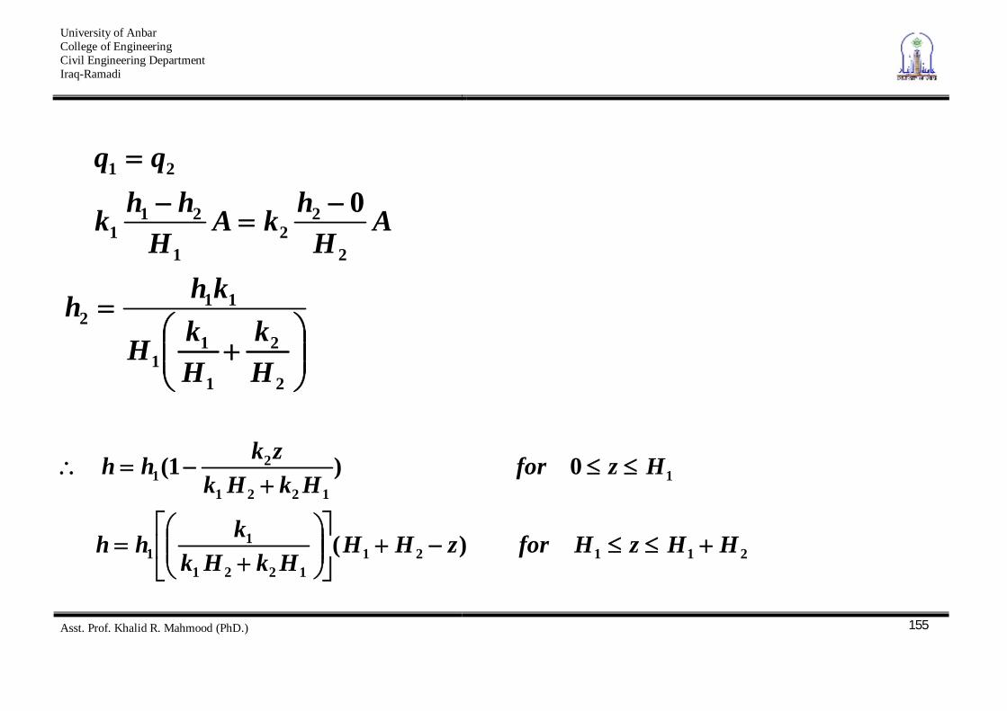
155
2
2
1
11
112
2
22
1
211
21
0
Hk
HkH
khh
AH
hkAH
hhk
211211221
11
11221
21
)(
0)1(
HHzHforzHHHkHk
khh
HzforHkHk
zkhh
University of Anbar College of Engineering Civil Engineering Department Iraq-Ramadi
Asst. Prof. Khalid R. Mahmood (PhD.)
156
Flow Nets The following methods are available for the determination of flow nets: 1. Graphical solution by sketching 2. Mathematical or analytical methods 3. Numerical analysis 4. Models 5. Analogy methods All the methods are based on Laplace’s continuity equation.
University of Anbar College of Engineering Civil Engineering Department Iraq-Ramadi
Asst. Prof. Khalid R. Mahmood (PhD.)
157
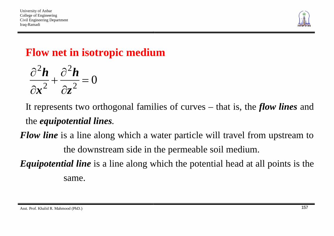
Flow net in isotropic medium
02
2
2
2
zh
xh
It represents two orthogonal families of curves – that is, the flow lines and the equipotential lines.
Flow line is a line along which a water particle will travel from upstream to the downstream side in the permeable soil medium.
Equipotential line is a line along which the potential head at all points is the same.
University of Anbar College of Engineering Civil Engineering Department Iraq-Ramadi
Asst. Prof. Khalid R. Mahmood (PhD.)
158

University of Anbar College of Engineering Civil Engineering Department Iraq-Ramadi
Asst. Prof. Khalid R. Mahmood (PhD.)
159
University of Anbar College of Engineering Civil Engineering Department Iraq-Ramadi
Asst. Prof. Khalid R. Mahmood (PhD.)
160
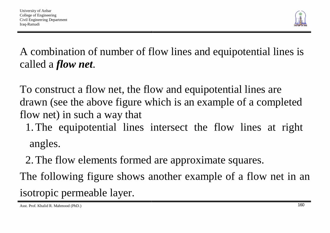
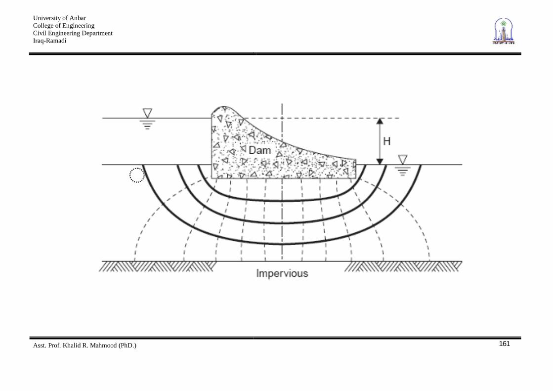
A combination of number of flow lines and equipotential lines is called a flow net. To construct a flow net, the flow and equipotential lines are drawn (see the above figure which is an example of a completed flow net) in such a way that
1. The equipotential lines intersect the flow lines at right angles.
2. The flow elements formed are approximate squares. The following figure shows another example of a flow net in an isotropic permeable layer.
University of Anbar College of Engineering Civil Engineering Department Iraq-Ramadi
Asst. Prof. Khalid R. Mahmood (PhD.)
161
University of Anbar College of Engineering Civil Engineering Department Iraq-Ramadi
Asst. Prof. Khalid R. Mahmood (PhD.)
162
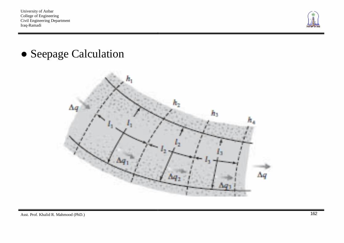
Seepage Calculation
University of Anbar College of Engineering Civil Engineering Department Iraq-Ramadi
Asst. Prof. Khalid R. Mahmood (PhD.)
163
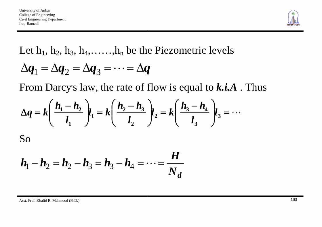
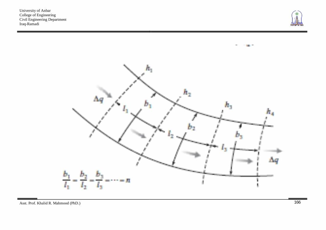
Let h1, h2, h3, h4,……,hn be the Piezometric levels
qqqq 321 From Darcy,s law, the rate of flow is equal to k.i.A . Thus
33
432
2
321
1
21 ll
hhkll
hhkll
hhkq
So
dNHhhhhhh 433221
University of Anbar College of Engineering Civil Engineering Department Iraq-Ramadi
Asst. Prof. Khalid R. Mahmood (PhD.)
164
potential drop between any adjacent equipotential lines And
dNHkq
Where H = the difference of head between the upstream and downstream sides Nd = number of potential drops
University of Anbar College of Engineering Civil Engineering Department Iraq-Ramadi
Asst. Prof. Khalid R. Mahmood (PhD.)
165
If the number of flow channels in a flow net is equal to Nf , then
.... HkNN
Hkqd
f
Where shape factor of the flow net
f
d
NN
University of Anbar College of Engineering Civil Engineering Department Iraq-Ramadi
Asst. Prof. Khalid R. Mahmood (PhD.)
166
University of Anbar College of Engineering Civil Engineering Department Iraq-Ramadi
Asst. Prof. Khalid R. Mahmood (PhD.)
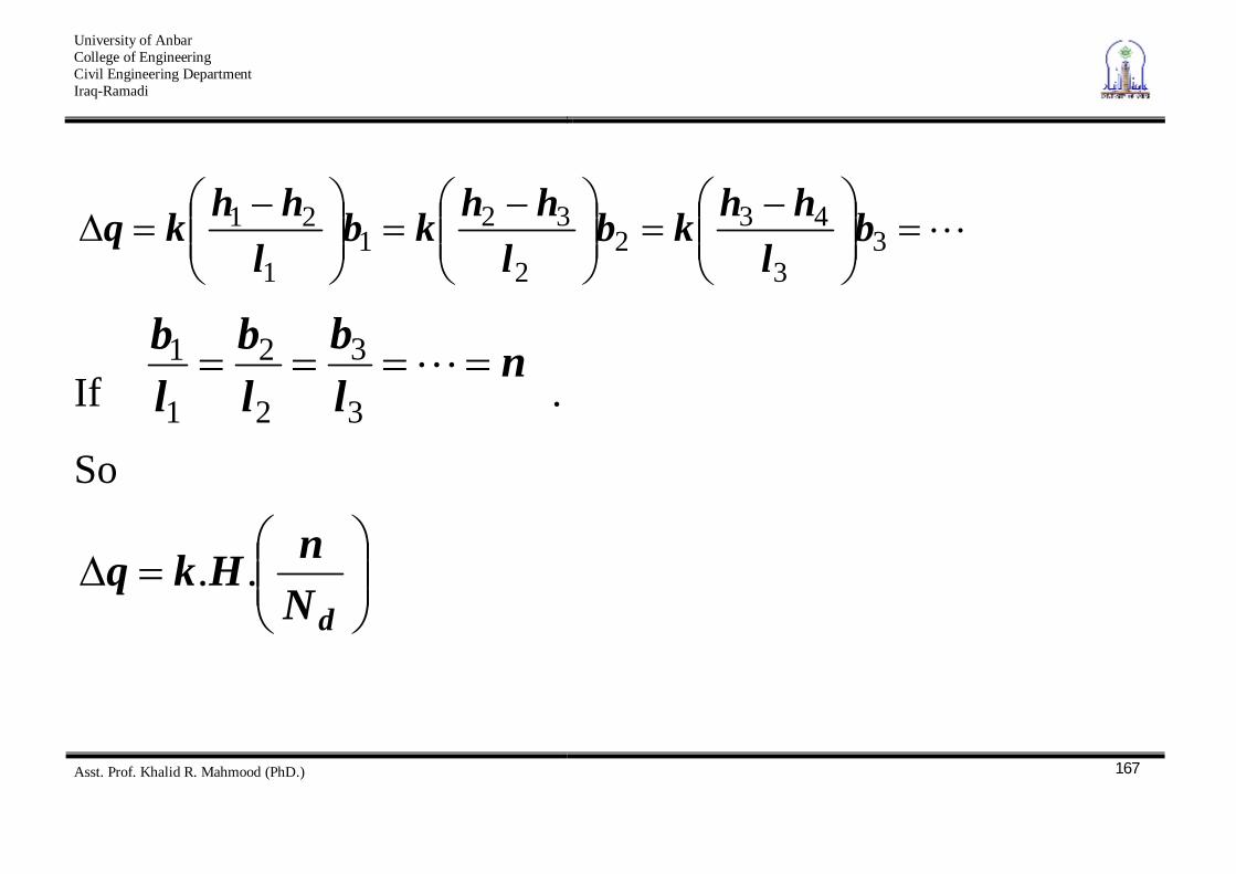
167
33
432
2
321
1
21 bl
hhkbl
hhkbl
hhkq
If n
lb
lb
lb
3
3
2
2
1
1 .
So
dNnHkq ..
University of Anbar College of Engineering Civil Engineering Department Iraq-Ramadi
Asst. Prof. Khalid R. Mahmood (PhD.)
168
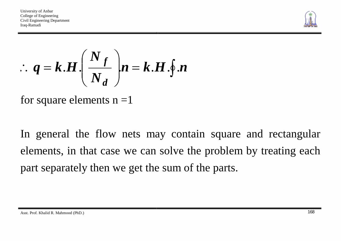
nHknNN
Hkqd
f ......
for square elements n =1 In general the flow nets may contain square and rectangular elements, in that case we can solve the problem by treating each part separately then we get the sum of the parts.
University of Anbar College of Engineering Civil Engineering Department Iraq-Ramadi
Asst. Prof. Khalid R. Mahmood (PhD.)
169
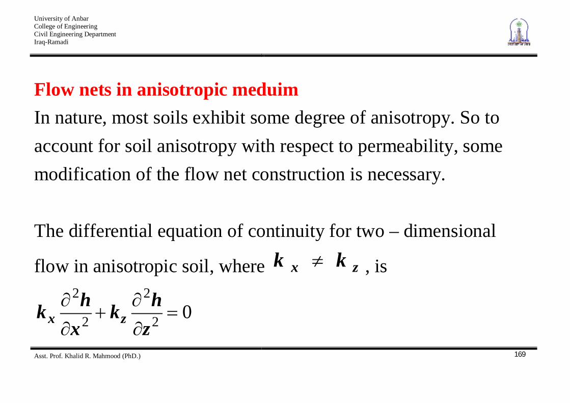
Flow nets in anisotropic meduim In nature, most soils exhibit some degree of anisotropy. So to account for soil anisotropy with respect to permeability, some modification of the flow net construction is necessary. The differential equation of continuity for two – dimensional
flow in anisotropic soil, where zx kk , is
02
2
2
2
zhk
xhk zx
University of Anbar College of Engineering Civil Engineering Department Iraq-Ramadi
Asst. Prof. Khalid R. Mahmood (PhD.)
170
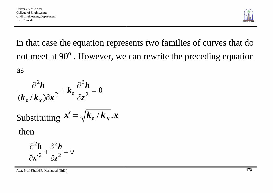
in that case the equation represents two families of curves that do not meet at 90o . However, we can rewrite the preceding equation as
0)/( 2
2
2
2
zhk
xkkh
zxz
Substituting xkkx xz ./ then
02
2
2
2
zh
xh
University of Anbar College of Engineering Civil Engineering Department Iraq-Ramadi
Asst. Prof. Khalid R. Mahmood (PhD.)
171
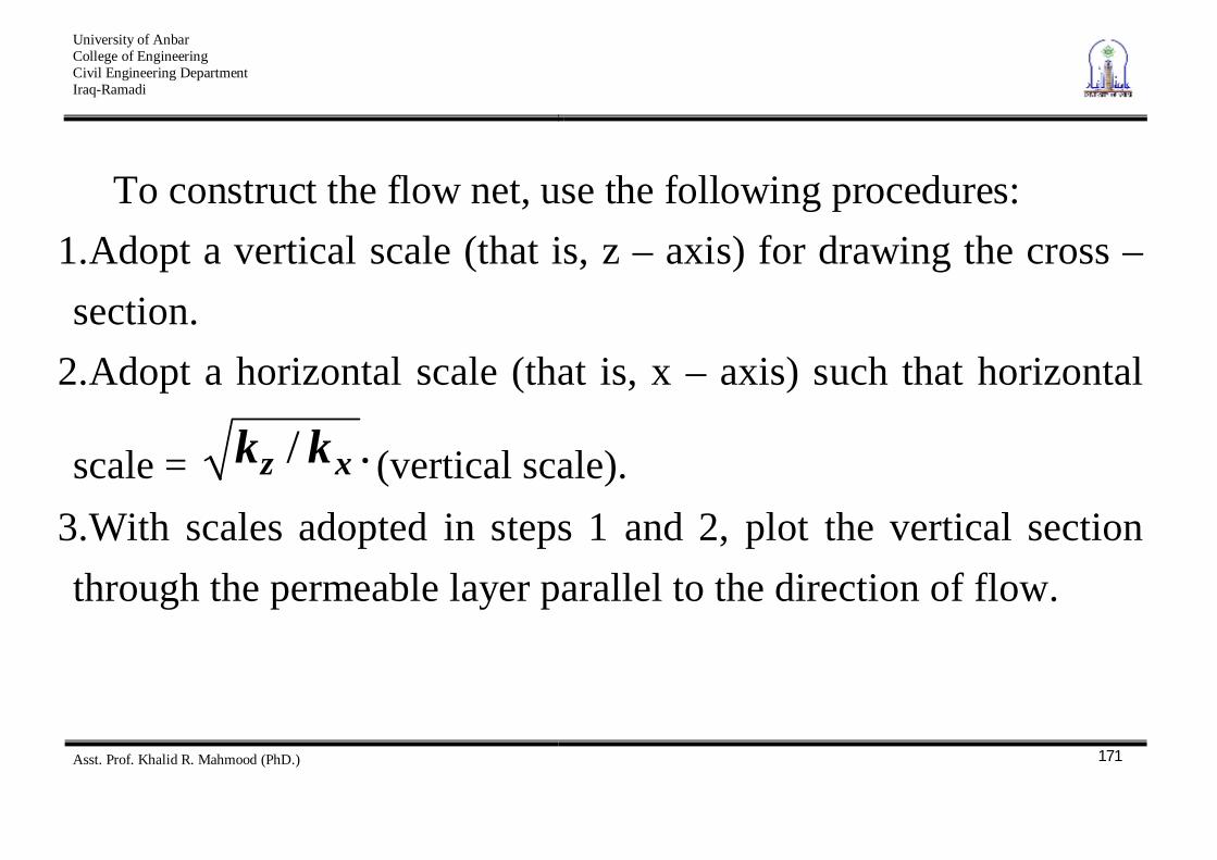
To construct the flow net, use the following procedures: 1. Adopt a vertical scale (that is, z – axis) for drawing the cross – section.
2. Adopt a horizontal scale (that is, x – axis) such that horizontal
scale = ./ xz kk (vertical scale). 3. With scales adopted in steps 1 and 2, plot the vertical section through the permeable layer parallel to the direction of flow.
University of Anbar College of Engineering Civil Engineering Department Iraq-Ramadi
Asst. Prof. Khalid R. Mahmood (PhD.)
172
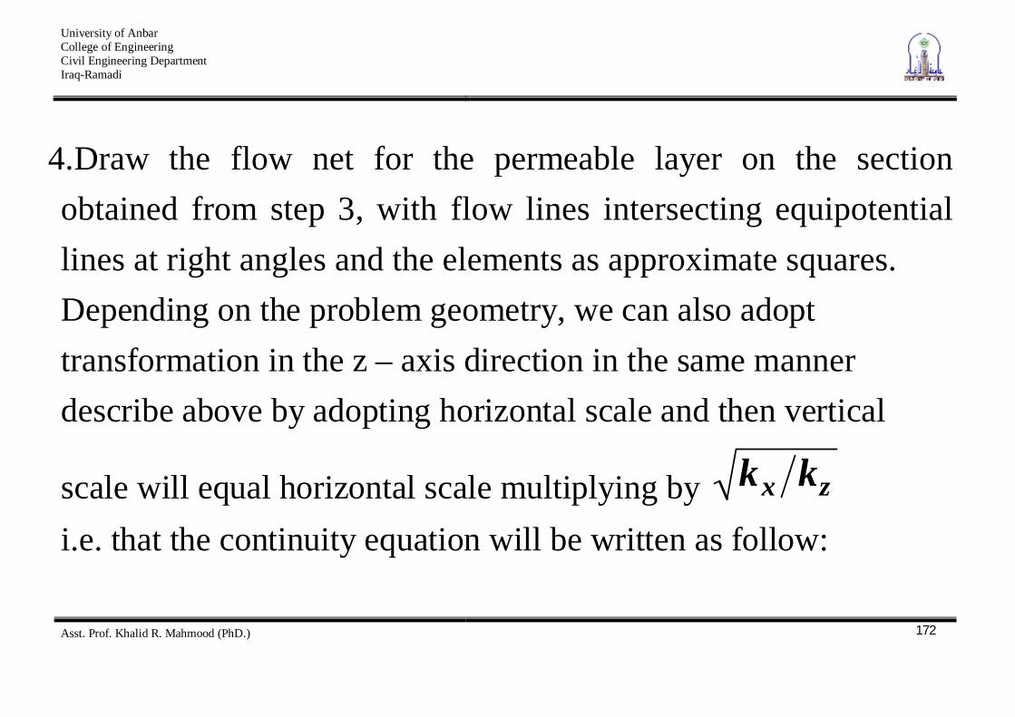
4. Draw the flow net for the permeable layer on the section obtained from step 3, with flow lines intersecting equipotential lines at right angles and the elements as approximate squares. Depending on the problem geometry, we can also adopt transformation in the z – axis direction in the same manner describe above by adopting horizontal scale and then vertical
scale will equal horizontal scale multiplying by zx kk i.e. that the continuity equation will be written as follow:
University of Anbar College of Engineering Civil Engineering Department Iraq-Ramadi
Asst. Prof. Khalid R. Mahmood (PhD.)
173
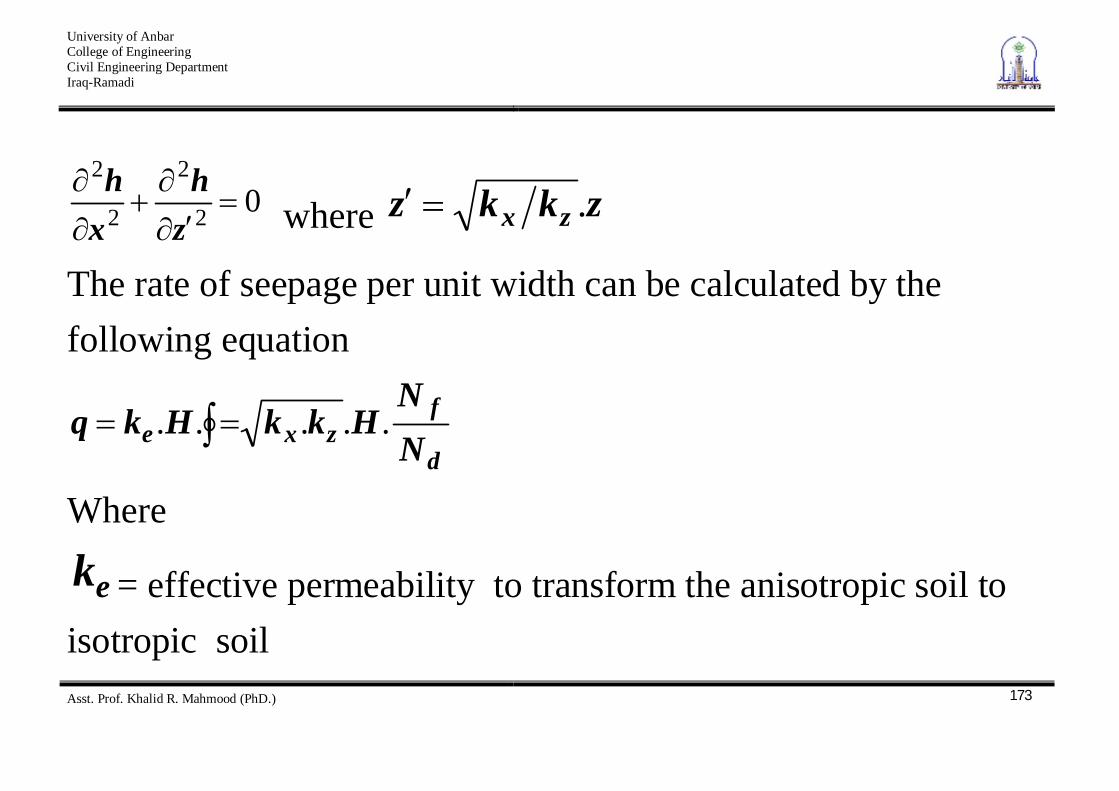
02
2
2
2
zh
xh
where zkkz zx .
The rate of seepage per unit width can be calculated by the following equation
d
fzxe N
NHkkHkq .....
Where
ek = effective permeability to transform the anisotropic soil to isotropic soil
University of Anbar College of Engineering Civil Engineering Department Iraq-Ramadi
Asst. Prof. Khalid R. Mahmood (PhD.)
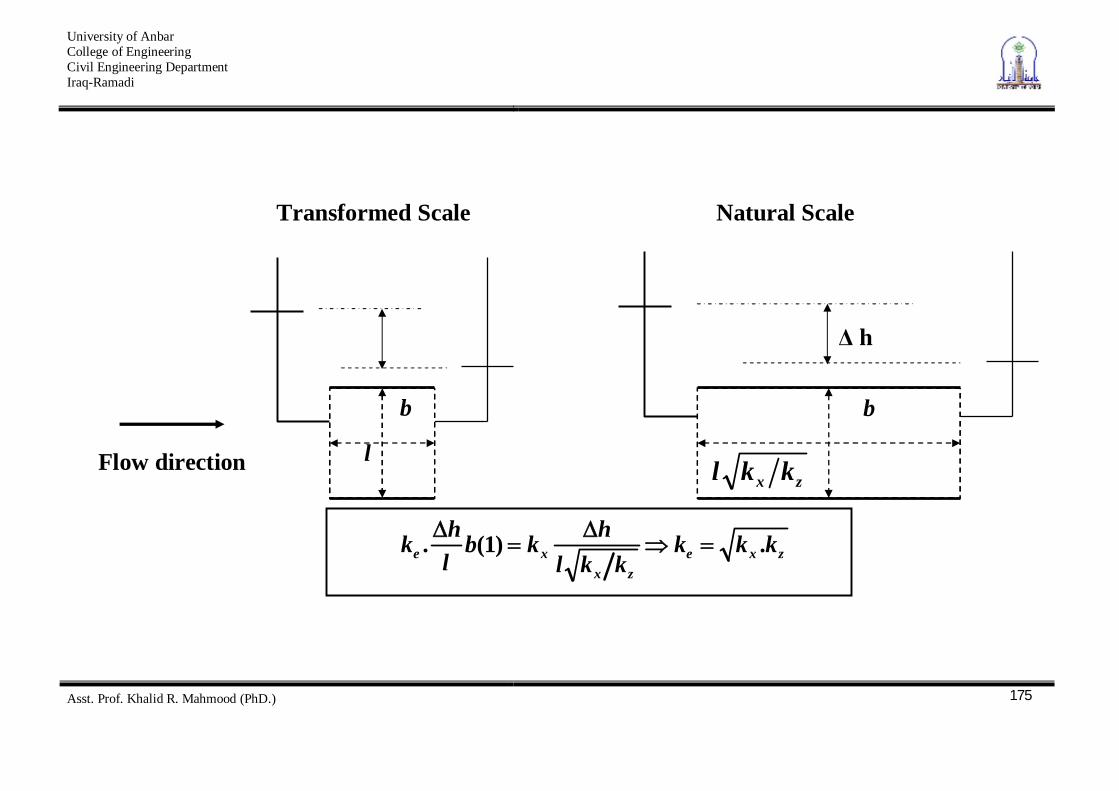
174
To prove that zxe kkk . whatever is the direction of flow let us consider two elements one from a flow net drawn in natural scale the other one drawn in transformed scale as shown below.
University of Anbar College of Engineering Civil Engineering Department Iraq-Ramadi
Asst. Prof. Khalid R. Mahmood (PhD.)
175
h
b
l
b
zx kkl Flow direction
Transformed Scale Natural Scale
zxezx
xe kkkkkl
hkblhk .)1(.
University of Anbar College of Engineering Civil Engineering Department Iraq-Ramadi
Asst. Prof. Khalid R. Mahmood (PhD.)
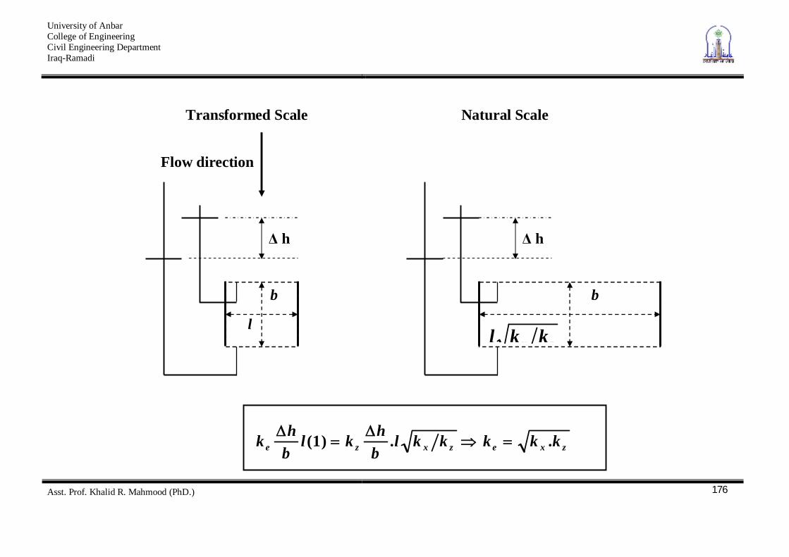
176
b
l
b
zx kkl
h h
Flow direction
Transformed Scale Natural Scale
zxezxze kkkkklbhkl
bhk ..)1(
University of Anbar College of Engineering Civil Engineering Department Iraq-Ramadi
Asst. Prof. Khalid R. Mahmood (PhD.)
177
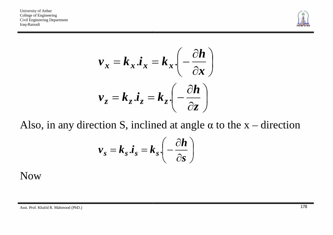
In the anisotropic soil, the permeability coefficient having a maximum value in the direction of stratification and a minimum value in the direction normal to that of stratification: these directions are devoted by x & z i.e.
maxkkx and minkkz From Darcy, s law
University of Anbar College of Engineering Civil Engineering Department Iraq-Ramadi
Asst. Prof. Khalid R. Mahmood (PhD.)
178
zhkikv
xhkikv
zzzz
xxxx
..
..
Also, in any direction S, inclined at angle to the x – direction
shkikv ssss ..
Now
University of Anbar College of Engineering Civil Engineering Department Iraq-Ramadi
Asst. Prof. Khalid R. Mahmood (PhD.)
179
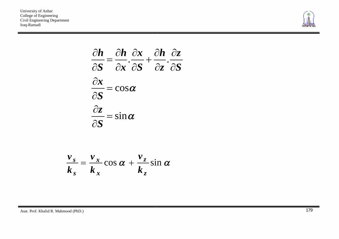
sin
cos
..
SzSx
Sz
zh
Sx
xh
Sh
sincosz
z
x
x
s
skv
kv
kv
University of Anbar College of Engineering Civil Engineering Department Iraq-Ramadi
Asst. Prof. Khalid R. Mahmood (PhD.)
180
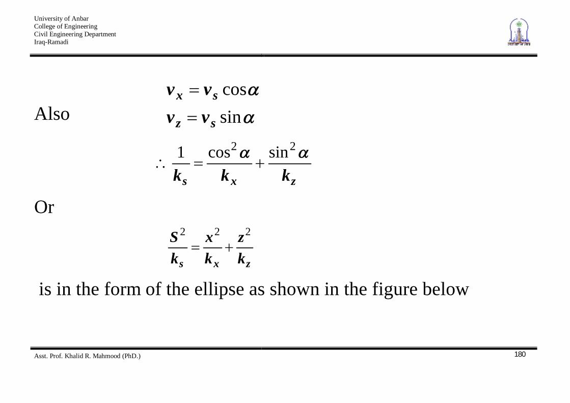
Also sincos
sz
sx
vvvv
zxs kkk
22 sincos1
Or
zxs k
zkx
kS 222
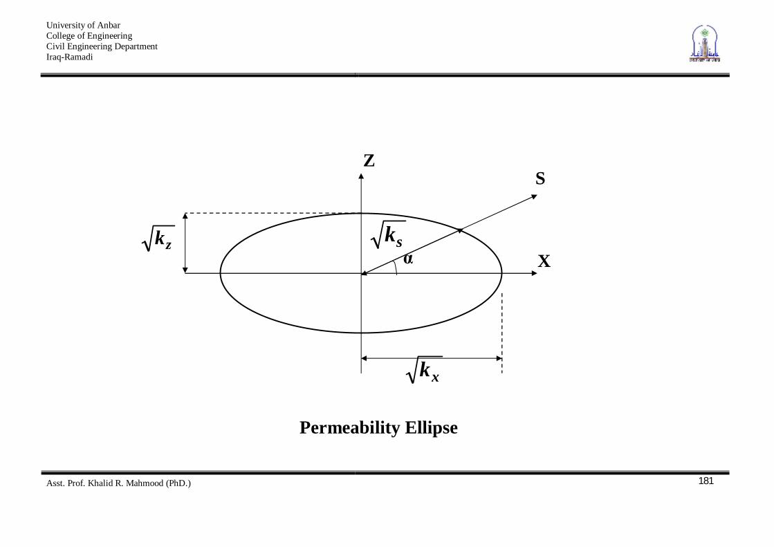
is in the form of the ellipse as shown in the figure below
University of Anbar College of Engineering Civil Engineering Department Iraq-Ramadi
Asst. Prof. Khalid R. Mahmood (PhD.)
181
Z
X
S
xk
zk
sk
Permeability Ellipse
University of Anbar College of Engineering Civil Engineering Department Iraq-Ramadi
Asst. Prof. Khalid R. Mahmood (PhD.)
182
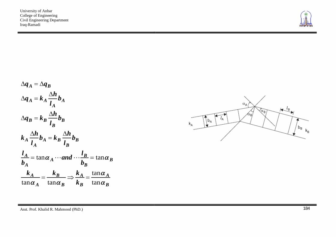
Transfer Condition In case of flow perpendicular to soil strata, the loss of head and rate of flow are influenced primarily by the less pervious soil whereas in the case of flow parallel to the strata, the rate of flow is essential controlled by comparatively more pervious soil. The following shows a flow channel (part of two – dimensional
flow net) going from soil A to soil B with BA kk (two layers). Based on the principle of continuity, i.e., the same rate of flow exists in the flow channel in soil A as in soil B, we can derive the
University of Anbar College of Engineering Civil Engineering Department Iraq-Ramadi
Asst. Prof. Khalid R. Mahmood (PhD.)
183
relationship between the angles of incident of the flow paths with the boundary for the two flow channels. Not only does the direction of flow change at a boundary between soils with different permeabilities, but also the geometry of the figures in the flow net changes. As can be seen in the figure below, the figures in soil B are not squares as is the case in soil A, but rather rectangles.
University of Anbar College of Engineering Civil Engineering Department Iraq-Ramadi
Asst. Prof. Khalid R. Mahmood (PhD.)
184
B
A
B
A
B
B
A
A
BB
BA
A
A
BB
BAA
A
BB
BB
AA
AA
BA
kkkk
bland
bl
bl
hkbl
hk
bl
hkq
bl
hkq
tantan
tantan
tantan
University of Anbar College of Engineering Civil Engineering Department Iraq-Ramadi
Asst. Prof. Khalid R. Mahmood (PhD.)
185
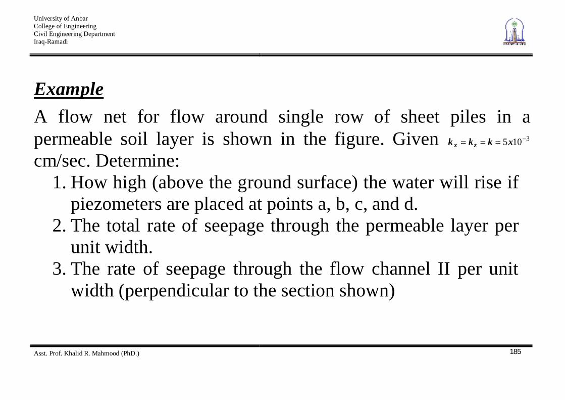
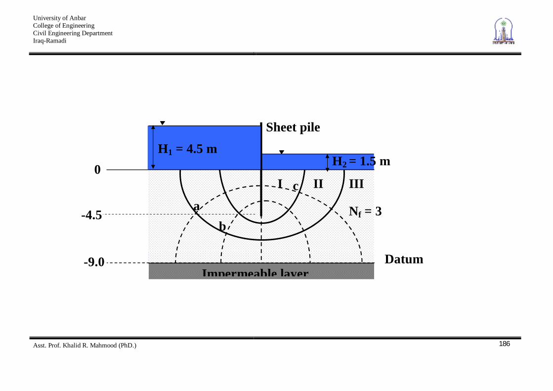
Example A flow net for flow around single row of sheet piles in a permeable soil layer is shown in the figure. Given 3105xkkk zx cm/sec. Determine:
1. How high (above the ground surface) the water will rise if piezometers are placed at points a, b, c, and d.
2. The total rate of seepage through the permeable layer per unit width.
3. The rate of seepage through the flow channel II per unit width (perpendicular to the section shown)
University of Anbar College of Engineering Civil Engineering Department Iraq-Ramadi
Asst. Prof. Khalid R. Mahmood (PhD.)
186
Sheet pile
H2 = 1.5 m H1 = 4.5 m
Impermeable layer
Nf = 3 a b
c I
II III 0
-4.5
-9.0 Datum
University of Anbar College of Engineering Civil Engineering Department Iraq-Ramadi
Asst. Prof. Khalid R. Mahmood (PhD.)
187
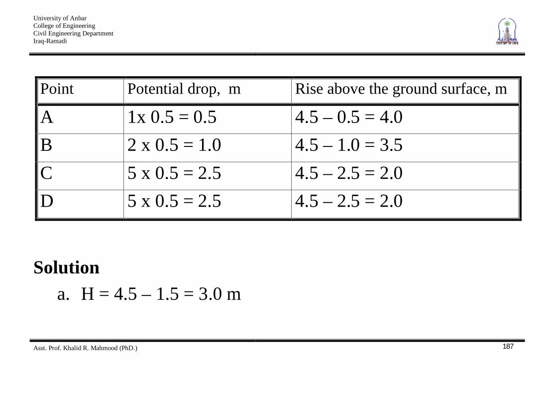
Point Potential drop, m Rise above the ground surface, m
A 1x 0.5 = 0.5 4.5 – 0.5 = 4.0 B 2 x 0.5 = 1.0 4.5 – 1.0 = 3.5 C 5 x 0.5 = 2.5 4.5 – 2.5 = 2.0 D 5 x 0.5 = 2.5 4.5 – 2.5 = 2.0
Solution a. H = 4.5 – 1.5 = 3.0 m
University of Anbar College of Engineering Civil Engineering Department Iraq-Ramadi
Asst. Prof. Khalid R. Mahmood (PhD.)
188
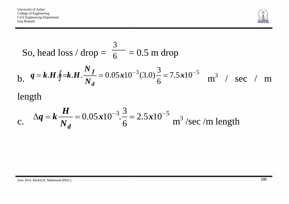
So, head loss / drop = 63
= 0.5 m drop
b. 53 105.7
63)0.3(1005.0.... xx
NN
HkHkqd
f m3 / sec / m
length
c. 53 105.2
63.1005.0 xx
NHkq
d m3 /sec /m length
University of Anbar College of Engineering Civil Engineering Department Iraq-Ramadi
Asst. Prof. Khalid R. Mahmood (PhD.)
189
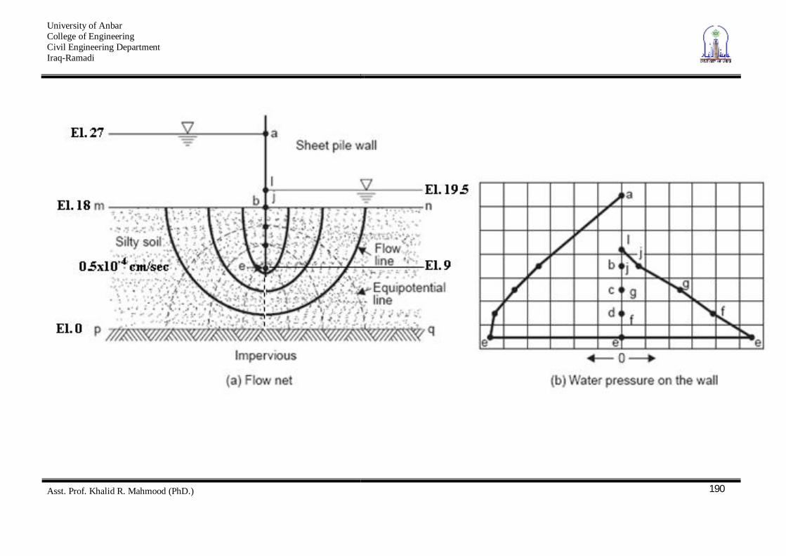
Seepage pressure and Uplift Pressure 1. Seepage Pressure on Sheet Piles
Example Given. Flow net in the following figure Find. Pore pressure at points a to i; quantity of seepage; exit gradient.
University of Anbar College of Engineering Civil Engineering Department Iraq-Ramadi
Asst. Prof. Khalid R. Mahmood (PhD.)
190
University of Anbar College of Engineering Civil Engineering Department Iraq-Ramadi
Asst. Prof. Khalid R. Mahmood (PhD.)
191
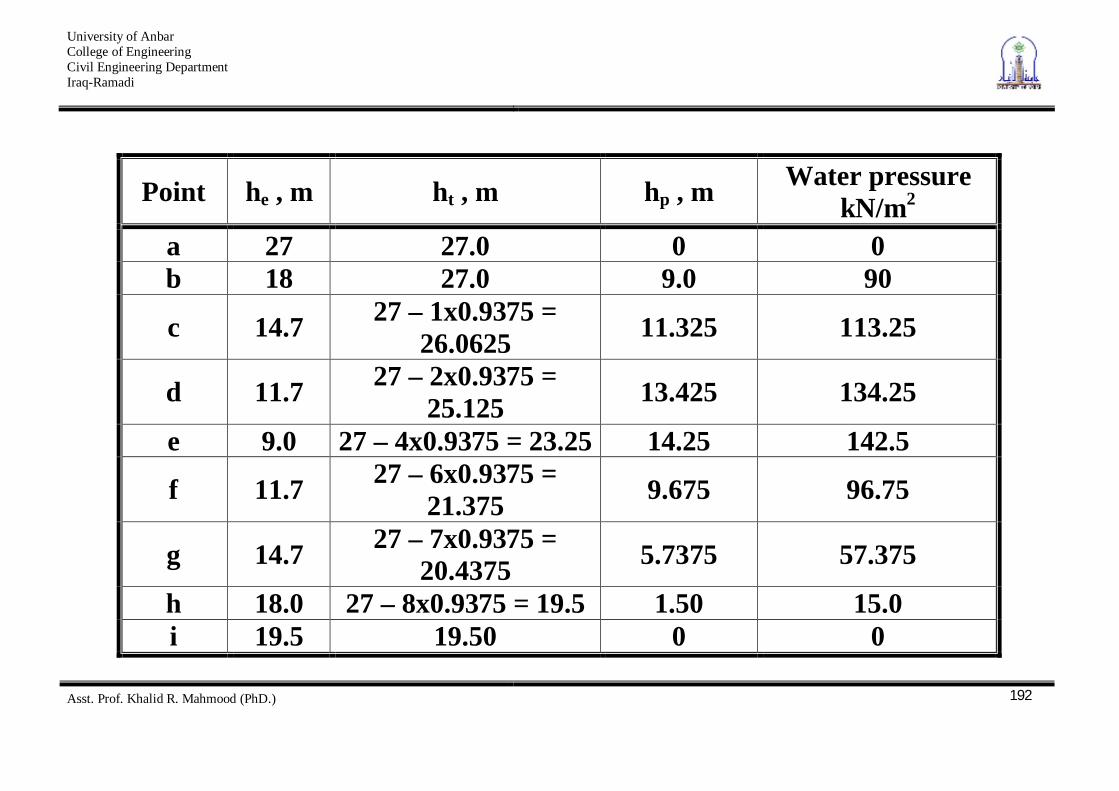
The water pressure plot, such shown in the above figure, is useful in the structural design of the wall and in study of water pressure differential tending to cause leakage through the wall.
Total head loss H = 27 – 19.5 =7.5 m Head loss /drop = 9375.085.7 m
Let w = 10 kN/m2
University of Anbar College of Engineering Civil Engineering Department Iraq-Ramadi
Asst. Prof. Khalid R. Mahmood (PhD.)
192
Point he , m ht , m hp , m Water pressure kN/m2
a 27 27.0 0 0 b 18 27.0 9.0 90
c 14.7 27 – 1x0.9375 = 26.0625 11.325 113.25
d 11.7 27 – 2x0.9375 = 25.125 13.425 134.25
e 9.0 27 – 4x0.9375 = 23.25 14.25 142.5
f 11.7 27 – 6x0.9375 = 21.375 9.675 96.75
g 14.7 27 – 7x0.9375 = 20.4375 5.7375 57.375
h 18.0 27 – 8x0.9375 = 19.5 1.50 15.0 i 19.5 19.50 0 0
University of Anbar College of Engineering Civil Engineering Department Iraq-Ramadi
Asst. Prof. Khalid R. Mahmood (PhD.)
193
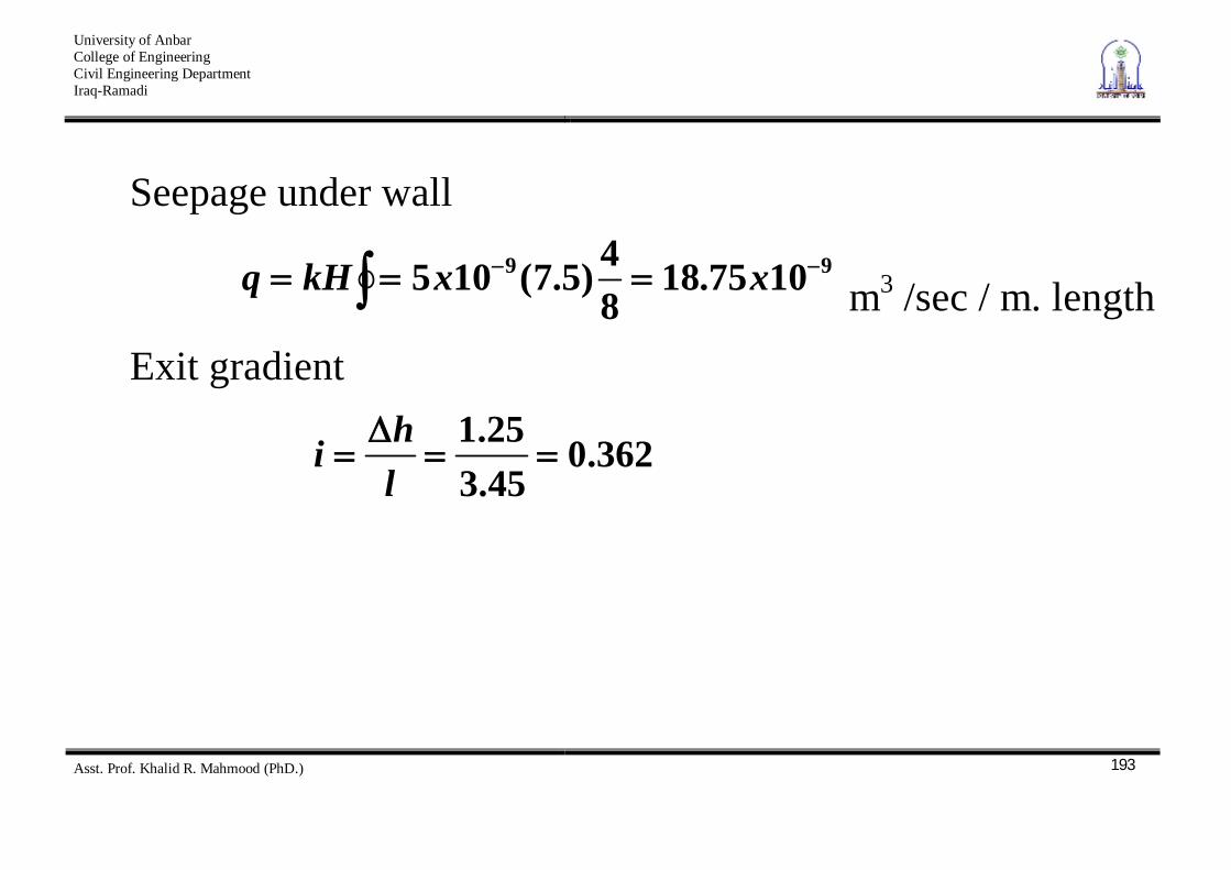
Seepage under wall
99 1075.18
84)5.7(105 xxkHq m3 /sec / m. length
Exit gradient
362.045.325.1
lhi
University of Anbar College of Engineering Civil Engineering Department Iraq-Ramadi
Asst. Prof. Khalid R. Mahmood (PhD.)
194
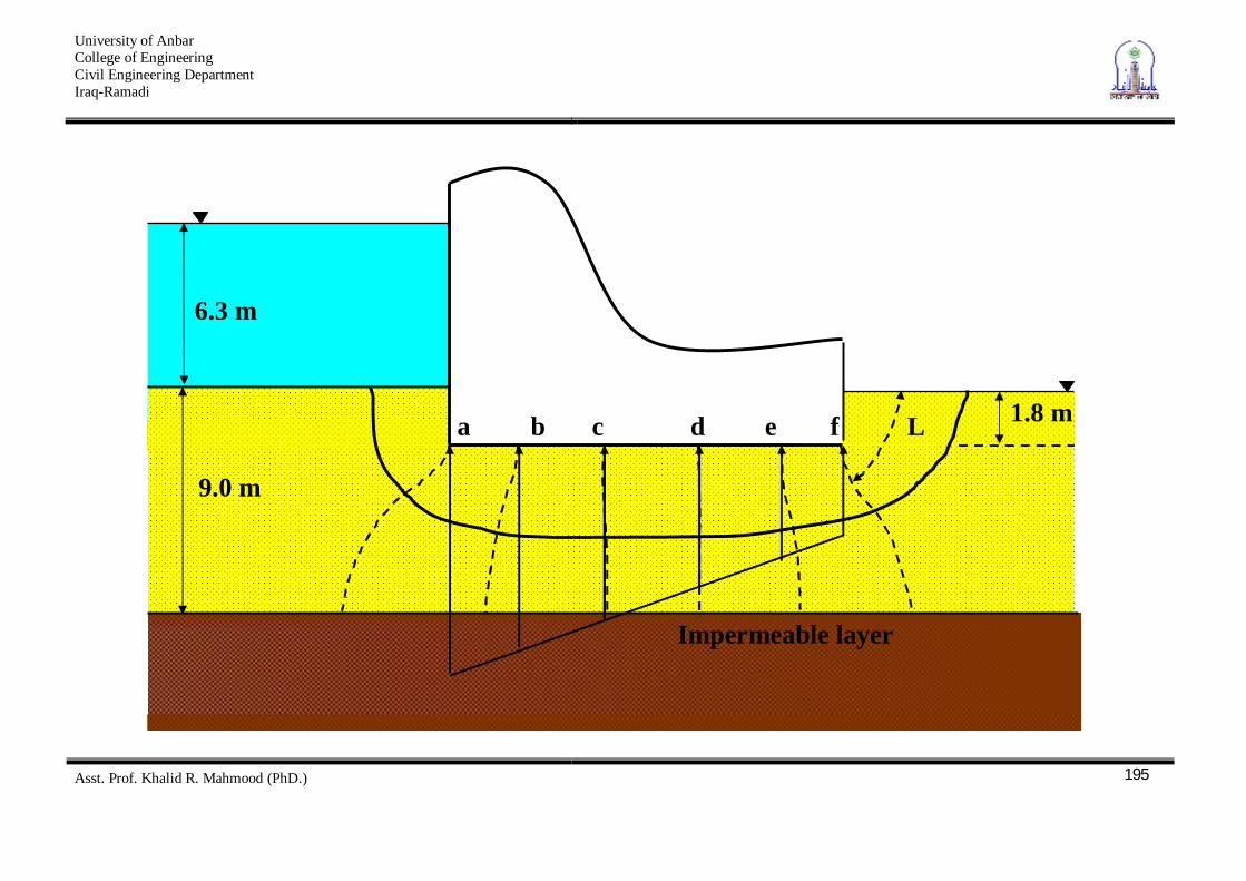
2. Uplift Pressure under Hydraulic structures Example The following figure shows a weir, the base of which is 1.8 m below the ground surface. The necessary flow net also been
drawn (assuming kkk zx ). H = 6.3 m. So, the loss of head for each potential drop is
9.073.67H m.
University of Anbar College of Engineering Civil Engineering Department Iraq-Ramadi
Asst. Prof. Khalid R. Mahmood (PhD.)
195
Impermeable layer
6.3 m
1.8 m
9.0 m
a b c d e f L
University of Anbar College of Engineering Civil Engineering Department Iraq-Ramadi
Asst. Prof. Khalid R. Mahmood (PhD.)
196
The total head at the ground level in the upstream side = 6.3 + 1.8 = 8.1 m Let w = 10 kN/m2
University of Anbar College of Engineering Civil Engineering Department Iraq-Ramadi
Asst. Prof. Khalid R. Mahmood (PhD.)
197
Point
Total head, ht Pressure head, hp
Uplift pressure, kN/m2 U = hp x w
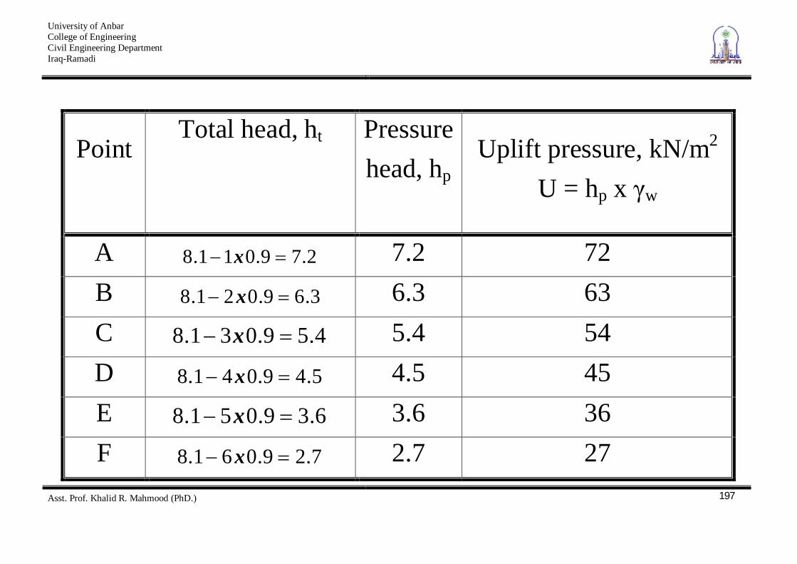
A 2.79.011.8 x 7.2 72 B 3.69.021.8 x 6.3 63 C 4.59.031.8 x 5.4 54 D 5.49.041.8 x 4.5 45 E 6.39.051.8 x 3.6 36 F 7.29.061.8 x 2.7 27
University of Anbar College of Engineering Civil Engineering Department Iraq-Ramadi
Asst. Prof. Khalid R. Mahmood (PhD.)
198
iexit = 0.9 / L High value of exit gradient will affect the stability of the structure and a factor of safety will be applied. This will discussed later
University of Anbar College of Engineering Civil Engineering Department Iraq-Ramadi
Asst. Prof. Khalid R. Mahmood (PhD.)
199
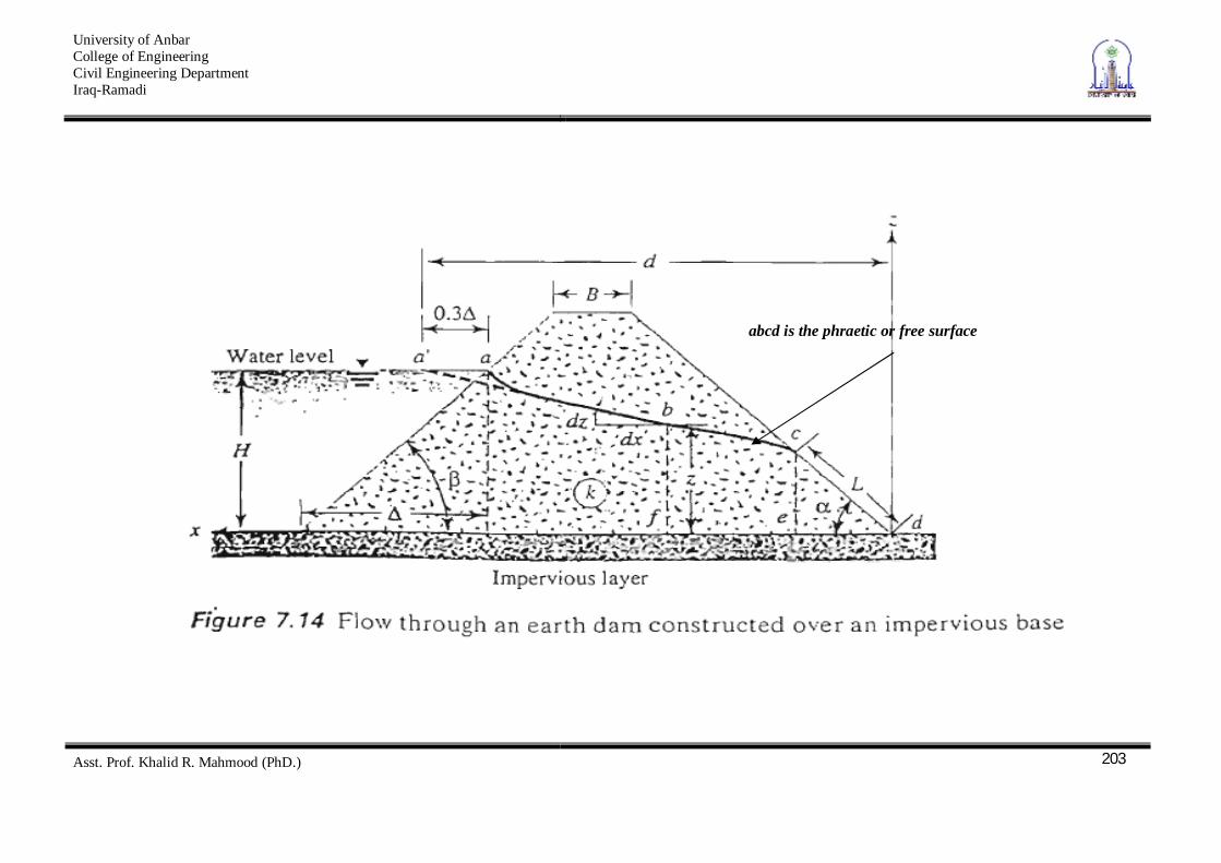
Seepage through an Earth Dam The flow through an earth dam differs from the other cases in that the top flow line is not know in advance of sketching the flow net. Thus, it is a case of unconfined flow. The top flow line as well as the flow net will be dependent upon the nature of internal drainage for the earth dam. Typical cases are shown in Fig. 6.8; the top flow line only is shown.

University of Anbar College of Engineering Civil Engineering Department Iraq-Ramadi
Asst. Prof. Khalid R. Mahmood (PhD.)
200
University of Anbar College of Engineering Civil Engineering Department Iraq-Ramadi
Asst. Prof. Khalid R. Mahmood (PhD.)
201
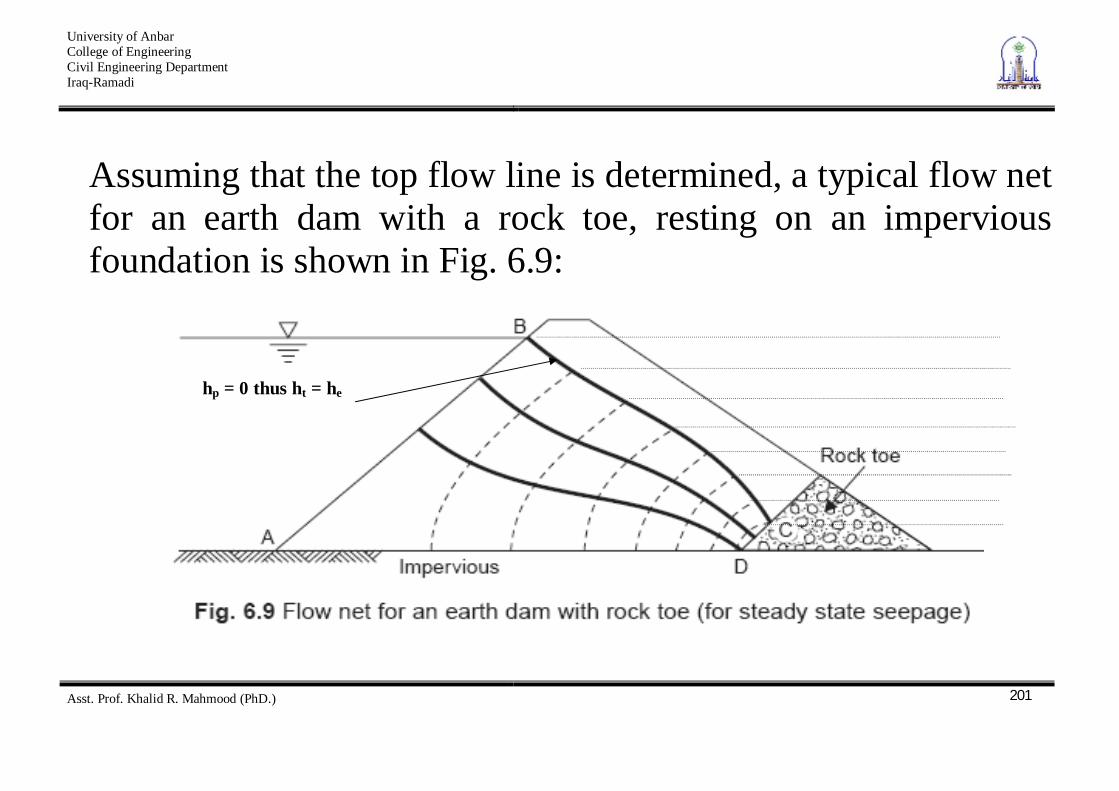
Assuming that the top flow line is determined, a typical flow net for an earth dam with a rock toe, resting on an impervious foundation is shown in Fig. 6.9:
hp = 0 thus ht = he
University of Anbar College of Engineering Civil Engineering Department Iraq-Ramadi
Asst. Prof. Khalid R. Mahmood (PhD.)
202
AB is known to be an equipotential and AD a flow line. BC is the top flow line; at all points of this line the pressure head is zero. Thus BC is also the ‘phreatic line’; or, on this line, the total head is equal to the elevation head. Line CD is neither an equipotential nor a flow line, but the total head equals the elevation head at all points of CD.
University of Anbar College of Engineering Civil Engineering Department Iraq-Ramadi
Asst. Prof. Khalid R. Mahmood (PhD.)
203
abcd is the phraetic or free surface
University of Anbar College of Engineering Civil Engineering Department Iraq-Ramadi
Asst. Prof. Khalid R. Mahmood (PhD.)
204
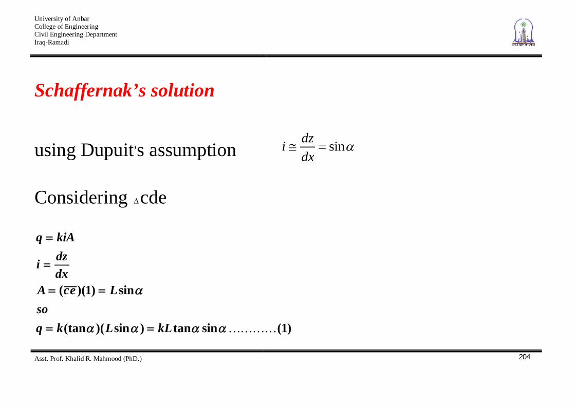
Schaffernak’s solution
using Dupuit,s assumption sindxdzi
Considering cde
)1(sintan)sin)((tan
sin)1)((
kLLkqso
LecAdxdzi
kiAq
University of Anbar College of Engineering Civil Engineering Department Iraq-Ramadi
Asst. Prof. Khalid R. Mahmood (PhD.)
205
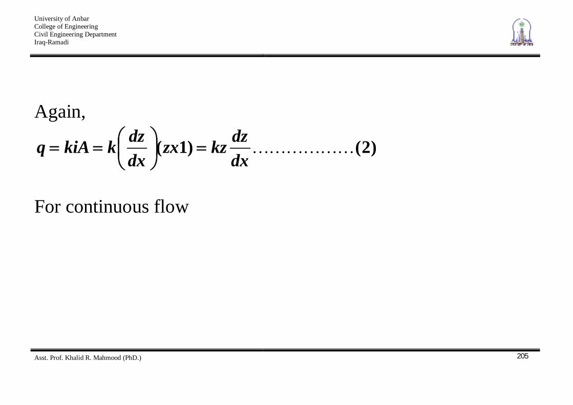
Again,
)2()1(dxdzkzzx
dxdzkkiAq
For continuous flow
University of Anbar College of Engineering Civil Engineering Department Iraq-Ramadi
Asst. Prof. Khalid R. Mahmood (PhD.)
206
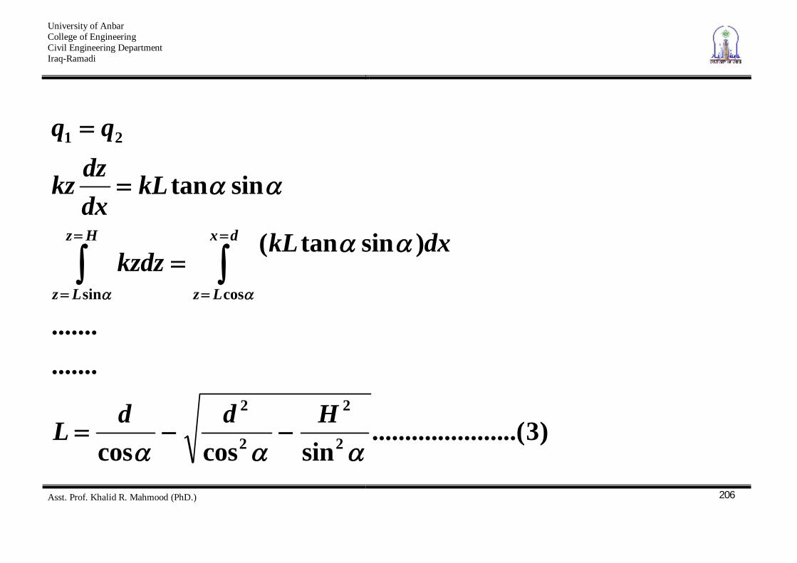
)3..(....................sincoscos
.......
.......
)sintan(
sintan
2
2
2
2
sin cos
21
HddL
dxkLkzdz
kLdxdzkz
Hz
Lz
dx
Lz
University of Anbar College of Engineering Civil Engineering Department Iraq-Ramadi
Asst. Prof. Khalid R. Mahmood (PhD.)
207
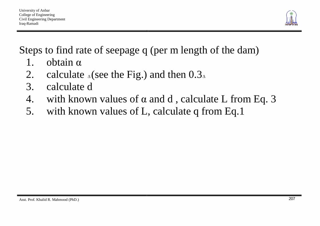
Steps to find rate of seepage q (per m length of the dam) 1. obtain 2. calculate (see the Fig.) and then 0.3 3. calculate d 4. with known values of and d , calculate L from Eq. 3 5. with known values of L, calculate q from Eq.1
University of Anbar College of Engineering Civil Engineering Department Iraq-Ramadi
Asst. Prof. Khalid R. Mahmood (PhD.)
208
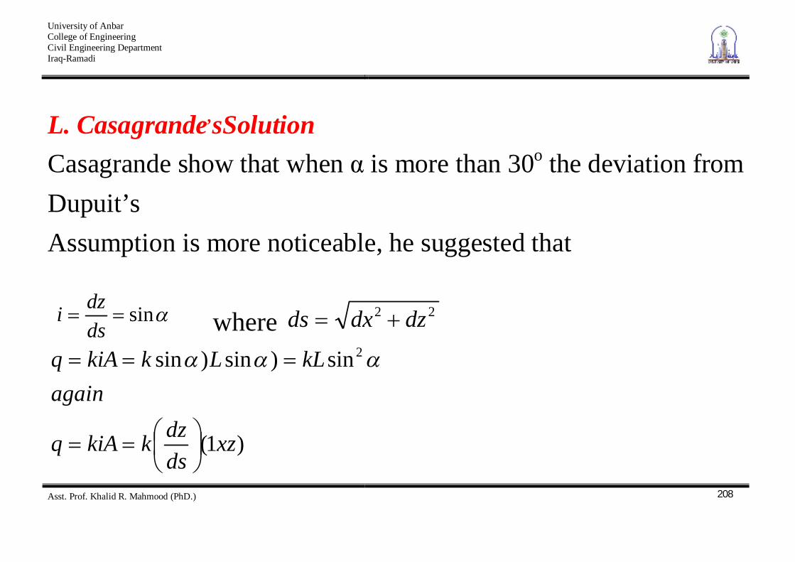
L. Casagrande,sSolution Casagrande show that when is more than 30o the deviation from Dupuit’s
Assumption is more noticeable, he suggested that
sindsdzi where 22 dzdxds
)1(
sin)sin)sin 2
xzdsdzkkiAq
againkLLkkiAq
University of Anbar College of Engineering Civil Engineering Department Iraq-Ramadi
Asst. Prof. Khalid R. Mahmood (PhD.)
209
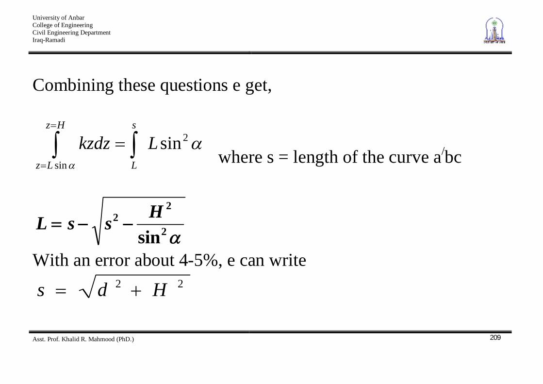
Combining these questions e get,
Hz
Lz
s
L
Lkzdzsin
2sin where s = length of the curve a/bc
2
22
sinHssL
With an error about 4-5%, e can write 22 Hds
University of Anbar College of Engineering Civil Engineering Department Iraq-Ramadi
Asst. Prof. Khalid R. Mahmood (PhD.)
210
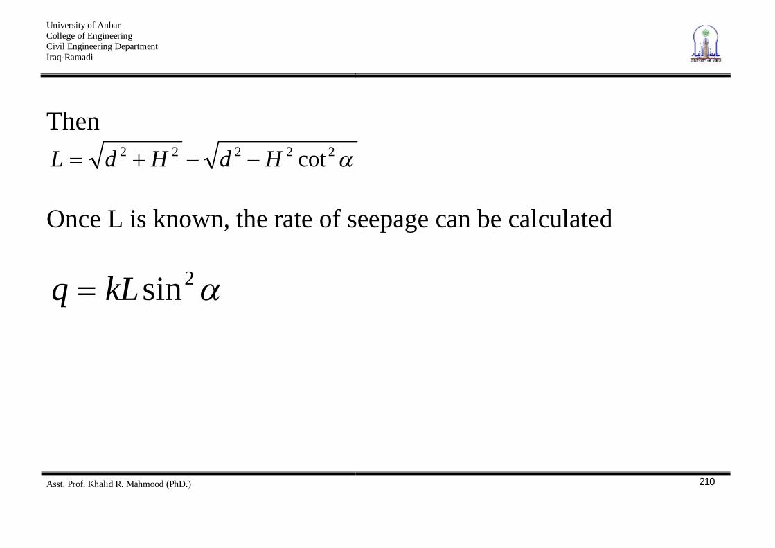
Then 22222 cotHdHdL
Once L is known, the rate of seepage can be calculated
2sinkLq
University of Anbar College of Engineering Civil Engineering Department Iraq-Ramadi
Asst. Prof. Khalid R. Mahmood (PhD.)
211
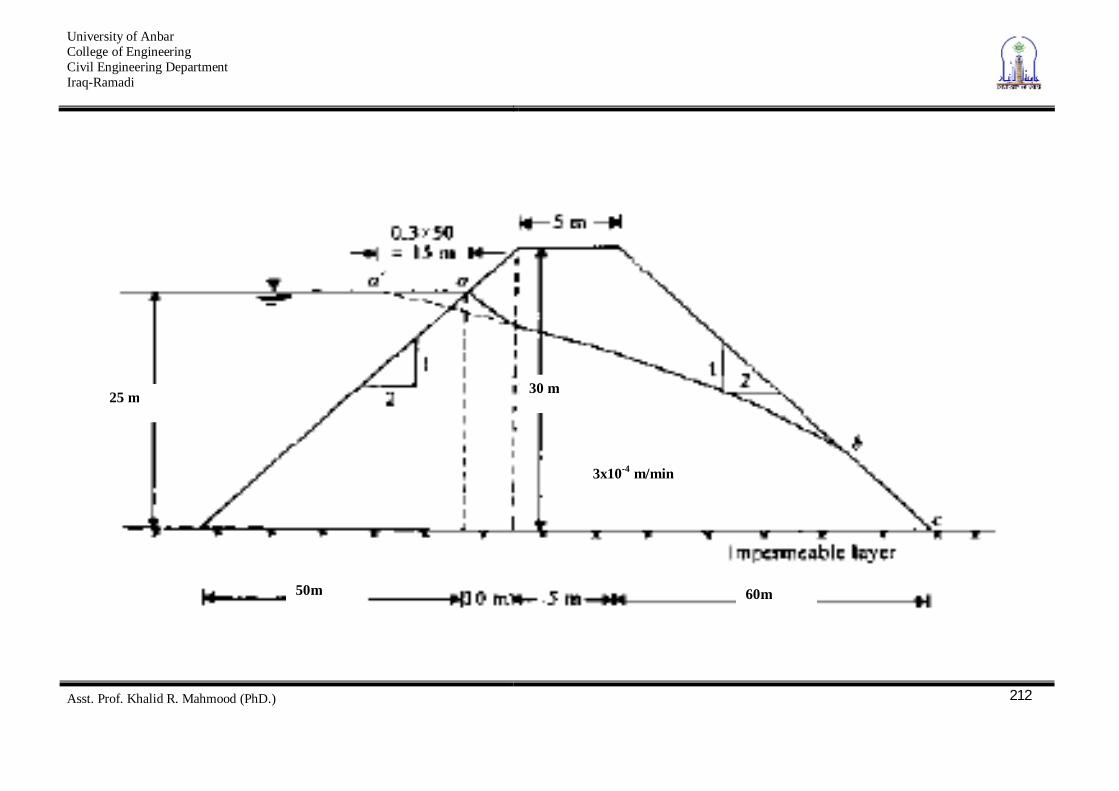
Example The cross-section of an earth dam is shown in Figure. Calculate the rate of seepage through the dam [q in m3/min ·m] by
1. Schaffernak’s solution 2. L. Casagrande’s method;
University of Anbar College of Engineering Civil Engineering Department Iraq-Ramadi
Asst. Prof. Khalid R. Mahmood (PhD.)
212
25 m 30 m
50m 60m
3x10⁻⁴ m/min
University of Anbar College of Engineering Civil Engineering Department Iraq-Ramadi
Asst. Prof. Khalid R. Mahmood (PhD.)
213
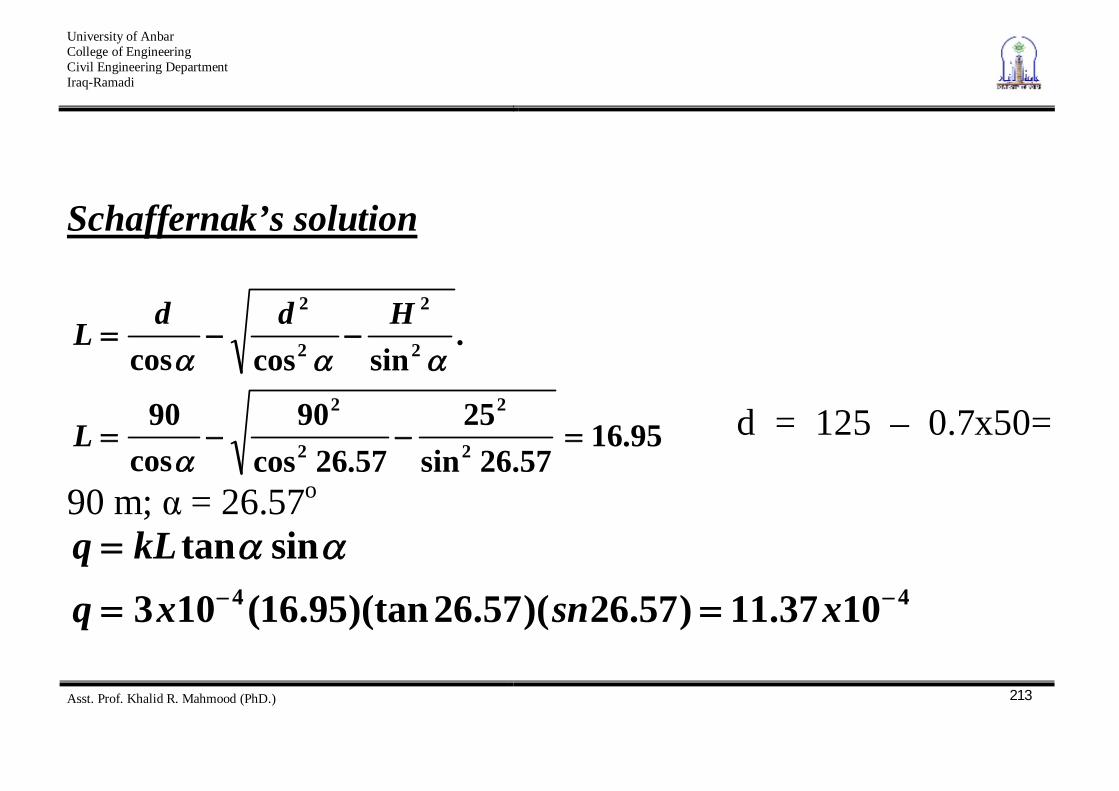
Schaffernak’s solution
95.1657.26sin
2557.26cos
90cos
90
.sincoscos
2
2
2
2
2
2
2
2
L
HddL
d = 125 – 0.7x50=
90 m; = 26.57o
44 1037.11)57.26)(57.26)(tan95.16(103sintan
xsnxqkLq
University of Anbar College of Engineering Civil Engineering Department Iraq-Ramadi
Asst. Prof. Khalid R. Mahmood (PhD.)
214
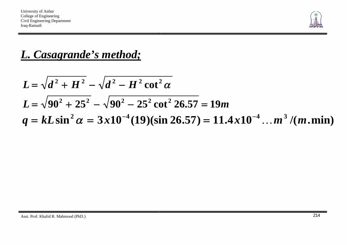
L. Casagrande’s method;
mL
HdHdL
1957.26cot25902590
cot22222
22222
min)./(104.11)57.26)(sin19(103sin 3442 mmxxkLq