Embed Size (px)
Citation preview
1©Copyright 2016, Mi-T-M Corporation EX-1036-120516
PARTS LIST FORAIR COMPRESSOR
AM2-PH09-08WPAM2-PM09-08WP
ENGINE OIL GRADE: SAE 10W-30 ENGINE OIL CAPACITY HONDA/Mi-T-M: 37 oz.MAXIMUM PRESSURE: 175 PSICOMPRESSOR OIL GRADE: SAE30W NON-DETERGENTCOMPRESSOR OIL CAPACITY: 40.5 oz. / 1.2 L
THE WORK PRO®
2©Copyright 2016, Mi-T-M Corporation EX-1036-120516
This Parts Listing has been compiled for your benefit. You can be assured your Mi-T-M Gasoline Air Compressor was constructed and designed with quality and performance in mind. Each component has been rigorously tested to insure the highest level of acceptance.
The contents of this Parts Listing are based on the latest product information available at the time of publication. Mi-T-M reserves the right to make changes in price, color, materials, equipment, specifications or models at any time without notice.
WARNING
THIS IS A PROFESSIONAL GASOLINE AIR COMPRESSOR. CAUTION SHOULD BE OBSERVED WHEN USING OR REPAIRING THIS UNIT! READ AND FOLLOW THE SAFETY WARNINGS LISTED BELOW BEFORE ATTEMPTING ANY REPAIRS ON THIS GASOLINE AIR COMPRESSOR!
SAFETY WARNINGS
1. NEVER alter or modify the equipment. Be sure any accessory items and system components being used will withstand the pressure developed Serious injury may occur from an air compressor malfunction or exploding accessories if incorrect system components, attachments or accessories are used. NEVER exceed manufactures maximum allowable pressure rating of attachments. Use only genuine Mi-T-M parts for repair of your air compressor. Failure to do so can cause hazardous operating conditions and will VOID warranty.2. NEVER make adjustments on machinery while the unit is connected to the engine without first removing the ignition cable from the spark plug. Turning over the machinery by hand during adjustment or cleaning might start the engine and machinery with it, causing serious injury to the operator. 3. Know how to stop and bleed pressures quickly. Be thoroughly familiar with controls. Do not operate without protective covers/ guards.4. Before servicing the unit, turn unit off, relieve the pressure and allow the unit to cool down. Service in a clean, dry, flat area. Block the wheels to prevent the unit from moving. Be especially careful to properly dispose of any flammable materials.5. After testing the machine, DO NOT leave the pressurized unit unattended. Shut off the unit and release pressure before leaving.
Table of Contents
SPECIFICATIONS ...........................................................................................................................................................................................................3FLOW CHART ................................................................................................................................................................................................................4GENERAL THEORY OF OPERATION ...........................................................................................................................................................................5TANK ASSEMBLY FOR AM2-PH09-08M AND AM2-PM09-08WP ................................................................................................................................6PUMP ASSEMBLY (3-0427) ...........................................................................................................................................................................................8PILOT VALVE (22-0270) .................................................................................................................................................................................................10
3©Copyright 2016, Mi-T-M Corporation EX-1036-120516
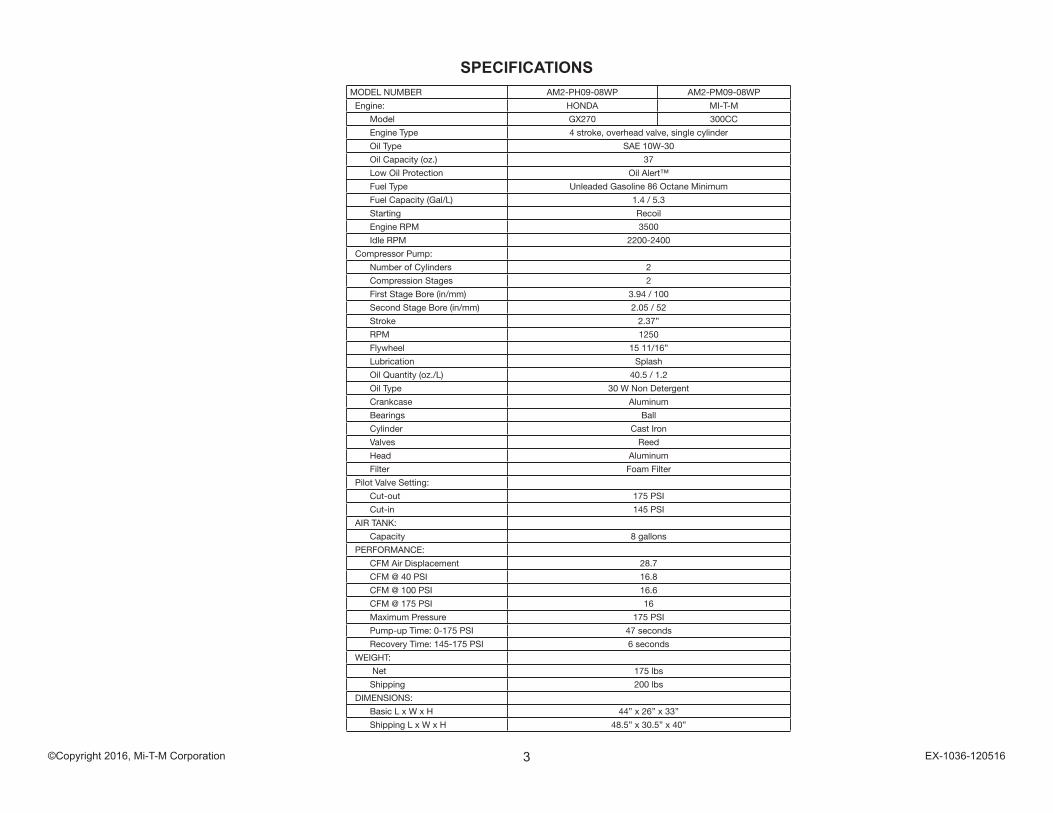
SPECIFICATIONSMODEL NUMBER AM2-PH09-08WP AM2-PM09-08WP
Engine: HONDA MI-T-M
Model GX270 300CC
Engine Type 4 stroke, overhead valve, single cylinder
Oil Type SAE 10W-30
Oil Capacity (oz.) 37
Low Oil Protection Oil Alert™
Fuel Type Unleaded Gasoline 86 Octane Minimum
Fuel Capacity (Gal/L) 1.4 / 5.3
Starting Recoil
Engine RPM 3500
Idle RPM 2200-2400
Compressor Pump:
Number of Cylinders 2
Compression Stages 2
First Stage Bore (in/mm) 3.94 / 100
Second Stage Bore (in/mm) 2.05 / 52
Stroke 2.37”
RPM 1250
Flywheel 15 11/16”
Lubrication Splash
Oil Quantity (oz./L) 40.5 / 1.2
Oil Type 30 W Non Detergent
Crankcase Aluminum
Bearings Ball
Cylinder Cast Iron
Valves Reed
Head Aluminum
Filter Foam Filter
Pilot Valve Setting:
Cut-out 175 PSI
Cut-in 145 PSI
AIR TANK:
Capacity 8 gallons
PERFORMANCE:
CFM Air Displacement 28.7
CFM @ 40 PSI 16.8
CFM @ 100 PSI 16.6
CFM @ 175 PSI 16
Maximum Pressure 175 PSI
Pump-up Time: 0-175 PSI 47 seconds
Recovery Time: 145-175 PSI 6 seconds
WEIGHT:
Net 175 lbs
Shipping 200 lbs
DIMENSIONS:
Basic L x W x H 44” x 26” x 33”
Shipping L x W x H 48.5” x 30.5” x 40”
4©Copyright 2016, Mi-T-M Corporation EX-1036-120516
OM
AC
0051
-102
898-
RD
FLOW CHART
5©Copyright 2016, Mi-T-M Corporation EX-1036-120516
GENERAL THEORY OF OPERATION
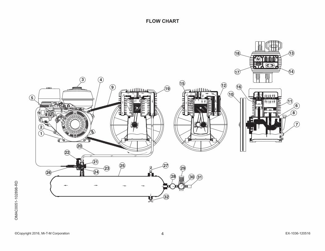
1. The ENGINE (1) supplies power to the air compressor. a. The ENGINE (1) is lubricated by oil. The oil level should be checked before each use by removing the ENGINE OIL DIPSTICK (2). b. The ENGINE (1) runs on gasoline. The FUEL TANK (3) level should be checked before each use. c. The ENGINE ON/OFF SWITCH (4) and STARTER ROPE (5) are used to start the engine. d. Refer to engine owner’s manual for appropriate starting procedures and requirements of the ENGINE (1).
2. The COMPRESSOR PUMP (6) is lubricated by oil. The oil level should be checked before each use by viewing the COMPRESSOR PUMP OIL SIGHTGLASS (7). If the oil level is low, add SAE-30W non-detergent oil to the COMPRESSOR PUMP OIL FILL PORT (8).
3. When the unit is operating, the V-BELT (9) turns the COMPRESSOR PUMP FLYWHEEL (10) which rotates the crankshaft and moves the pistons.
4 As the FIRST STAGE PISTON (11) moves down, air is drawn in through the INLET AIR FILTER (12). Then through the FIRST STAGE INLET REED VALVES (13) and into the first stage piston chamber. At the same time, the FIRST STAGE OUTLET REED VALVES (14) is closed. This allows air to fill the first stage piston chamber.
5. As the FIRST STAGE PISTON (11) moves upward, the FIRST STAGE INLET REED VALVE (13) closes. The FIRST STAGE OUTLET REED VALVE (14) opens allowing the compressed air to flow into the INTERCOOLER (15) and into the second stage.
6. As the SECOND STAGE PISTON (16) moves down, the first stage compressed air is drawn in the through the SECOND STAGE INLET REED VALVES (17) and into the second stage piston chamber. At the same time, the SECOND STAGE OUTLET REED VALVES (18) is closed.
7. As the SECOND STAGE PISTON (16) moves upward, the SECOND STAGE INLET REED VALVES (17) closes. The SECOND STAGE OUTLET REED VALVES (18) opens allowing the compressed air to flow into the AFTERCOOLER (19) and DISCHARGE LINE (20).
8. The compressed air then enters the PILOT CONTROL VALVE (21) which has an TOGGLE KNOB (22) with two positions. a. Easy Start Position: When the TOGGLE KNOB (22) is in the open position (vertical) air moves out the PILOT VALVE MUFFLER (23) allowing the ENGINE (1) to start under no-load conditions . b. Constant Run Position: When the TOGGLE KNOB (22) is in the closed position (horizontal) the compressed air opens the CHECK VALVE (24) and moves into the AIR TANK (25). When the pressure in the AIR TANK (25) reaches the maximum pressure setting of the PILOT CONTROL VALVE (21), the excess air exits the PILOT VALVE MUFFLER (23) and the CHECK VALVE (24) will close. At the same time the THROTTLE CONTROL (26) allows the ENGINE (1) to idle down.
9. The SAFETY RELIEF VALVE (27) protects the system from any overpressure conditions.
10. The TANK PRESSURE GAUGE (28) indicates tank pressure. The AIR PRESSURE REGULATOR (29) can be adjusted to the desired operating pressure which is indicated on the OUTLET PRESSURE GAUGE (30). The air exits through the OUTLET FITTING (31).
11. The ENGINE ON/OFF SWITCH (4) stops the ENGINE (1) when moved to the “OFF” position.
12. When the ENGINE (1) is off, compressed air should be released from the AIR TANK (25) by opening the attached air tool or by pulling on the SAFETY RELIEF VALVE (27). When the TANK PRESSURE GAUGE (28) registers less than 10 PSI, drain the condensation from the AIR TANK (25) by opening the TANK DRAIN (32).
6©Copyright 2016, Mi-T-M Corporation EX-1036-120516
AM
2-P
H09
& P
M09
-08W
P 11
3016
ALCTANK ASSEMBLY FOR AM2-PH09-08M AND AM2-PM09-08WP
7©Copyright 2016, Mi-T-M Corporation EX-1036-120516
AM2-PH09 & PM09-08WP 113016
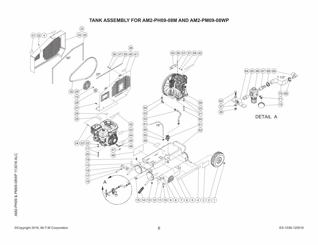
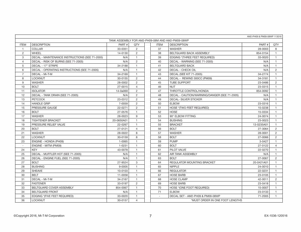
TANK ASSEMBLY FOR AM2-PH09-08M AND AM2-PM09-08WP
ITEM DESCRIPTION PART # QTY ITEM DESCRIPTION PART # QTY
1 COLLAR 33-0351 2 37 WASHER 28-0003 8
2 WHEEL 14-0130 2 38 BELTGUARD BACK ASSEMBLY 854-0154 1
3 DECAL - MAINTENANCE INSTRUCTIONS (SEE 71-2005) N/A 1 39 EDGING *(THREE FEET REQUIRED) 33-0020 1
4 DECAL - RISK OF BURNS (SEE 71-2005) N/A 2 40 DECAL - WARNING (SEE 71-2005) N/A 1
5 DECAL - 17” STRIPE 34-2188 1 41 BELTGUARD BACK N/A 1
6 DECAL - OPERATING INSTRUCTIONS (SEE 71-2005) N/A 1 42 DECAL - CHECK OIL N/A 2
7 DECAL - Mi-T-M 34-2169 1 43 DECAL (SEE KIT 71-2005) 34-2774 1
8 LOCKNUT 30-0155 2 44 DECAL - REWIND 300CC (PM09) 34-3181 1
9 WASHER 28-0002 2 45 TUBE SUPPORT 23-0486 2
10 BOLT 27-0015 4 46 NUT 23-0315 1
11 ISOLATOR 14-0a069 2 47 THROTTLE CONTROL/HONDA 854-0092 1
12 DECAL - TANK DRAIN (SEE 71-2005) N/A 2 48 DECAL - CAUTION/WARNING/DANGER (SEE 71-2005) N/A 1
13 PETCOCK 23-0312 2 49 DECAL- SILVER STICKER N/A 1
14 HANDLE GRIP 7-0059 2 50 ELBOW 23-0316 1
15 PRESSURE GAUGE 22-0271 2 51 HOSE *(TWO FEET REQUIRED) 15-0238 1
16 BOLT 27-0576 1 52 HOSE 15-0334 1
17 WASHER 28-0023 9 53 90° ELBOW FITTING 24-0074 1
18 TIGHTENER BRACKET 20-0650A01 1 54 BUSHING 23-0023 1
19 PRESSURE RELIEF VALVE 22-0267 1 55 BRACKET 13-0235A01 1
20 BOLT 27-0121 4 56 BOLT 27-3064 2
21 WASHER 28-0022 8 57 WASHER 28-0001 2
22 LOCKNUT 30-0159 8 58 BOLT 27-0066 2
23 ENGINE - HONDA (PH09) 1-0065 1 59 PUMP 3-0427 1
- ENGINE - MITM (PM09) 1-0231 1 60 BOLT 27-0122 4
24 KEY 43-0078 1 61 PILOT VALVE 22-0270 1
25 DECAL - MUFFLER HOT (SEE 71-2005) N/A 1 62 AIR TANK ASSEMBLY N/A 1
26 DECAL - ENGINE FUEL (SEE 71-2005) N/A 1 63 BOLT 27-0067 2
27 BOLT 27-9524 3 64 REGULATOR MOUNTING BRACKET 20-0421A01 1
28 BUSHING 9-0005 1 65 NIPPLE 24-0010 1
29 SHEAVE 10-0103 1 66 REGULATOR 22-0231 1
30 BELT 11-0058 1 67 HOSE BARB 23-0105 1
31 DECAL - Mi-T-M 34-2167 1 68 HOSE CLAMP 42-0011 2
32 FASTENER 33-0197 2 69 HOSE BARB 23-0418 1
33 BELTGUARD COVER ASSEMBLY 854-0067 1 70 HOSE *(ONE FOOT REQUIRED) 15-0007 1
34 BELTGUARD FRONT N/A 1 71 ELBOW 23-0133 1
35 EDGING *(FIVE FEET REQUIRED) 33-0020 1 - DECAL SET - AM2-PH09 & PM09-08WP 71-2005 1
36 LOCKNUT 30-0157 4 *MUST ORDER IN ONE FOOT LENGTHS
8©Copyright 2016, Mi-T-M Corporation EX-1036-120516
3-04
27 0
3071
6 A
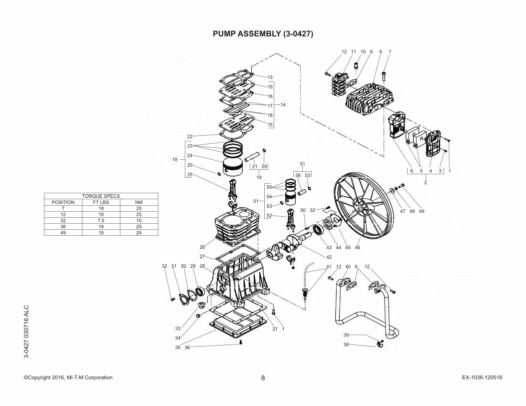
LCPUMP ASSEMBLY (3-0427)

9©Copyright 2016, Mi-T-M Corporation EX-1036-120516
3-0427 030716 ALC
PUMP ASSEMBLY
ITEM DESCRIPTION PART # QTY ITEM DESCRIPTION PART # QTY
1 SCREW 27-8433 8 30 REAR COVER GASKET (SEE KIT 70-0687) SEE KIT 1
2 AIR FILTER ASSY KIT (INC. 3-6) 70-0683 1 31 REAR CRANKCASE COVER 46-1675 1
3 SCREW (SEE KIT 70-0683) 27-8901 1 32 BOLT 27-8906 6
4 AIR FILTER COVER (SEE KIT 70-0683) SEE KIT 1 33 OIL SIGHT GLASS 46-1657 1
5 AIR FILTER (SEE KIT 70-0683) 19-0285 2 34 PLUG 39-0368 1
6 AIR FILTER HOUSING (SEE KIT 70-0683) SEE KIT 1 35 CRANKCASE BOTTOM PAN 46-1676 1
7 BOLT 27-8466 6 36 BOLT 27-8878 12
8 PUMP HEAD 46-1671 1 37 CRANKCASE BOTTOM GASKET (SEE KIT 70-0687) SEE KIT 1
9 AFTERCOOLER GASKET (SEE KIT 70-0687) SEE KIT 3 38 AFTERCOOLER BRACKET 13-0242 1
10 SAFETY VALVE 22-0505 1 39 SCREW 27-8189 1
11 AFTERCOOLER 46-1672 1 40 INTERCOOLER HOSE 46-1677 1
12 BOLT 27-8432 6 41 OIL DIPSTICK ASSY 39-0385 1
13 PUMP HEAD GASKET (SEE KIT 70-0687) SEE KIT 1 42 CRANKSHAFT 46-1678 1
14 REED VALVE ASSY KIT (INC. 15-18) 70-0684 1 43 BALL BEARING 48-0106 1
15 REED VALVE PLATE (SEE KIT 70-0684) SEE KIT 2 44 OIL SEAL (SEE KIT 70-0687) SEE KIT 1
16 VALVE PLATE MIDDLE GASKET (SEE KIT 70-0684) SEE KIT 1 45 FRONT CRANKCASE COVER 46-1679 1
17 HP REED VALVE (SEE KIT 70-0684) SEE KIT 2 46 FLYWHEEL 10-0166 1
18 LP REED VALVE (SEE KIT 70-0684) SEE KIT 4 47 WASHER 28-0022 1
19 PISTON ASSY KIT (INC. 20, 21, 23, 24, 25) 70-0685 1 48 LOCKWASHER 28-1009 1
20 LP SNAP RING (SEE KIT 70-0685) SEE KIT 2 49 BOLT 27-8062 1
21 LP PISTON PIN (SEE KIT 70-0685) SEE KIT 1 50 KEY 43-0149 1
22 CYLINDER GASKET (SEE KIT 70-0687) SEE KIT 1 51 HIGH PRESSURE ASSY KIT (INC. 52-56) 70-0686 1
23 LP PISTON RING ASSY (SEE KIT 70-0685) 46-1673 1 52 HP CONNECTING ROD (SEE KIT 70-0686) SEE KIT 1
24 LP PISTON (SEE KIT 70-0685) SEE KIT 1 53 HP SNAP RING (SEE KIT 70-0686) SEE KIT 2
25 LP CONNECTING ROD (SEE KIT 70-0685) SEE KIT 1 54 HP PISTON (SEE KIT 70-0686) SEE KIT 1
26 CYLINDER 46-1681 1 55 HP PISTON RING ASSY (SEE KIT 70-0686) 46-1680 1
27 CRANKCASE TOP GASKET (SEE KIT 70-0687) SEE KIT 1 56 HP PISTON PIN (SEE KIT 70-0686) SEE KIT 1
28 CRANKCASE 46-1674 1 - SET OF GASKETS KIT (INC. 9, 13, 22, 27, 30, 37, 44) 70-0687 1
29 BALL BEARING 48-0097 1

10©Copyright 2016, Mi-T-M Corporation EX-1036-120516
PILOT VALVE (22-0270)22
-027
0-06
2905
-DLG
11©Copyright 2016, Mi-T-M Corporation EX-1036-120516
22-0270-062905-DLG
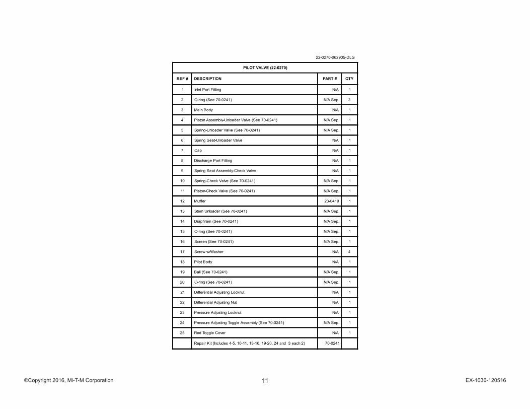
PILOT VALVE (22-0270)
REF # DESCRIPTION PART # QTY
1 Inlet Port Fitting N/A 1
2 O-ring (See 70-0241) N/A Sep. 3
3 Main Body N/A 1
4 Piston Assembly-Unloader Valve (See 70-0241) N/A Sep. 1
5 Spring-Unloader Valve (See 70-0241) N/A Sep. 1
6 Spring Seat-Unloader Valve N/A 1
7 Cap N/A 1
8 Discharge Port Fitting N/A 1
9 Spring Seat Assembly-Check Valve N/A 1
10 Spring-Check Valve (See 70-0241) N/A Sep. 1
11 Piston-Check Valve (See 70-0241) N/A Sep. 1
12 Muffler 23-0419 1
13 Stem Unloader (See 70-0241) N/A Sep. 1
14 Diaphram (See 70-0241) N/A Sep. 1
15 O-ring (See 70-0241) N/A Sep. 1
16 Screen (See 70-0241) N/A Sep. 1
17 Screw w/Washer N/A 4
18 Pilot Body N/A 1
19 Ball (See 70-0241) N/A Sep. 1
20 O-ring (See 70-0241) N/A Sep. 1
21 Differential Adjusting Locknut N/A 1
22 Differential Adjusting Nut N/A 1
23 Pressure Adjusting Locknut N/A 1
24 Pressure Adjusting Toggle Assembly (See 70-0241) N/A Sep. 1
25 Red Toggle Cover N/A 1
Repair Kit (Includes 4-5, 10-11, 13-16, 19-20, 24 and 3 each 2) 70-0241
12©Copyright 2016, Mi-T-M Corporation EX-1036-120516
Manufactured by Mi-T-M50 MI-T-M Drive, Peosta IA 52068563-556-7484/ Fax 563-556-1235