Embed Size (px)
Citation preview
THE MANUFACTURING, MECHANISM,
OPERATION AND USES OF OPTICAL
FIBER AND COMMUNICATION
OPTICAL COMMUNICATION
Page 1 of 15
OPTICAL
COMMUNICATION
INDEX:
1. Introduction ---------------------------------------------------------------- 2
2. Manufacturing of optical fibers ---------------------------------------- 3
2.1. Manufacturing of preform ------------------------------------ 4
2.2. Drawing the fibers --------------------------------------------- 6
2.3. Test and measurements ------------------------------------- 6
3. Operation and mechanism --------------------------------------------- 7
3.1. Fiber optic technology ---------------------------------------- 7
3.2. Types of optical cables --------------------------------------- 8
3.3. Fiber links -------------------------------------------------------- 9
4. Fiber optic communication ---------------------------------------------- 10
4.1. Transmitters ------------------------------------------------------ 10
4.1.1. Light emitting diode -------------------------------- 10
4.1.2. Laser diode ------------------------------------------ 11
4.2. Receivers --------------------------------------------------------- 12
4.2.1. Photodiode ------------------------------------------- 12
4.2.2. Phototransistor -------------------------------------- 13
4.3. Optical amplifiers ----------------------------------------------- 14
5. References ------------------------------------------------------------------ 16
Done by:
Anas Jalal Sulaiman
Andrew Achraf William
Toka Mohamed Rashad
Ahmed Hatem el Sharkawy
Mariam Emad
Abdelrahman Amr El-Adawy
Page 2 of 15
1. Introduction:
What are optical communication links?
Definition: Optical communication links where the signal light is
transported in fibers
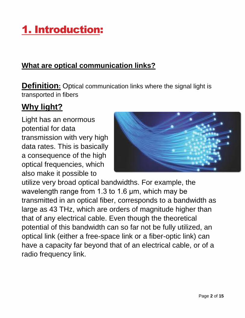
Why light?
Light has an enormous
potential for data
transmission with very high
data rates. This is basically
a consequence of the high
optical frequencies, which
also make it possible to
utilize very broad optical bandwidths. For example, the
wavelength range from 1.3 to 1.6 μm, which may be
transmitted in an optical fiber, corresponds to a bandwidth as
large as 43 THz, which are orders of magnitude higher than
that of any electrical cable. Even though the theoretical
potential of this bandwidth can so far not be fully utilized, an
optical link (either a free-space link or a fiber-optic link) can
have a capacity far beyond that of an electrical cable, or of a
radio frequency link.
Page 3 of 15
2. Manufacturing of optical fiber
Introduction:
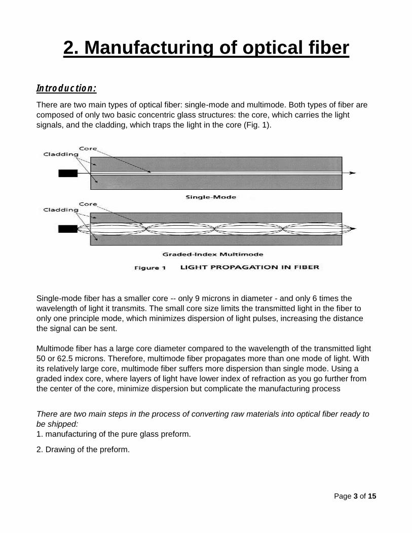
There are two main types of optical fiber: single-mode and multimode. Both types of fiber are
composed of only two basic concentric glass structures: the core, which carries the light
signals, and the cladding, which traps the light in the core (Fig. 1).
Single-mode fiber has a smaller core -- only 9 microns in diameter - and only 6 times the
wavelength of light it transmits. The small core size limits the transmitted light in the fiber to
only one principle mode, which minimizes dispersion of light pulses, increasing the distance
the signal can be sent.
Multimode fiber has a large core diameter compared to the wavelength of the transmitted light
50 or 62.5 microns. Therefore, multimode fiber propagates more than one mode of light. With
its relatively large core, multimode fiber suffers more dispersion than single mode. Using a
graded index core, where layers of light have lower index of refraction as you go further from
the center of the core, minimize dispersion but complicate the manufacturing process
There are two main steps in the process of converting raw materials into optical fiber ready to
be shipped:
1. manufacturing of the pure glass preform.
2. Drawing of the preform.
Page 4 of 15
2.1. Manufacturing the Preform: The first step in manufacturing glass optical fibers is to make a solid glass rod, known as a preform. Ultra-pure chemicals -- primarily silicon tetrachloride (SiCl4) and germanium tetrachloride (GeCl4) -- are converted into glass during preform manufacturing. These chemicals are used in varying proportions to fabricate the core regions for the different types of preforms. The basic chemical reaction of manufacturing optical glass is: SiCl4 (gas) + O2 > SiO2 (solid) + 2Cl2 (in the presence of heat) GeCl4 (gas) + O2 > GeO2 (solid) + 2Cl2 (in the presence of heat) The core composition of all standard communication fibers consists primarily of silica, with varying amounts of Germania added to increase the fiber's refractive index to the desired level. Single-mode fibers typically have only small amounts of Germania and have a uniform composition within the core. Multimode fibers typically have a much higher refractive index, and therefore much higher Germania content. There are several methods used to manufacture preforms. In the Modified Chemical Vapor Deposition (MCVD) process, the highly controlled mixture of chemicals described above is passed through the inside of a rotating glass tube made of pure synthetic SiO2.
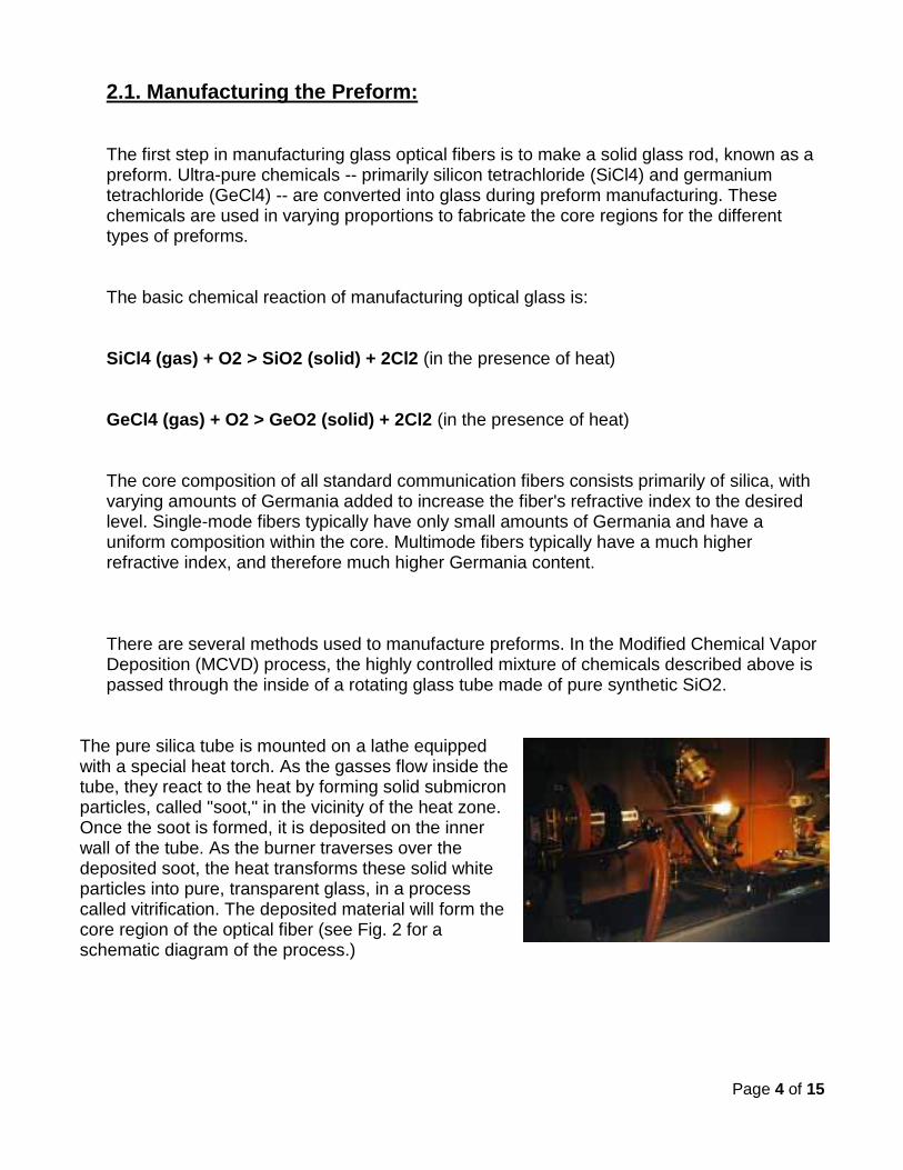
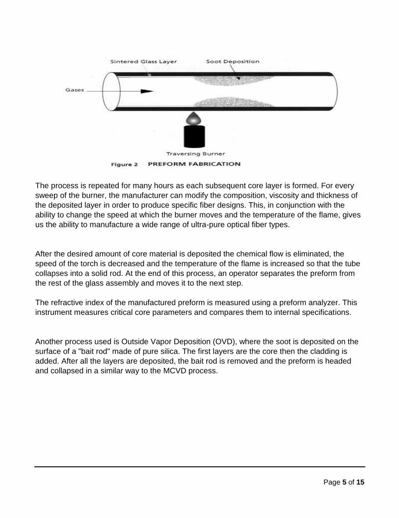
The pure silica tube is mounted on a lathe equipped with a special heat torch. As the gasses flow inside the tube, they react to the heat by forming solid submicron particles, called "soot," in the vicinity of the heat zone. Once the soot is formed, it is deposited on the inner wall of the tube. As the burner traverses over the deposited soot, the heat transforms these solid white particles into pure, transparent glass, in a process called vitrification. The deposited material will form the core region of the optical fiber (see Fig. 2 for a schematic diagram of the process.)
Page 5 of 15
The process is repeated for many hours as each subsequent core layer is formed. For every
sweep of the burner, the manufacturer can modify the composition, viscosity and thickness of
the deposited layer in order to produce specific fiber designs. This, in conjunction with the
ability to change the speed at which the burner moves and the temperature of the flame, gives
us the ability to manufacture a wide range of ultra-pure optical fiber types.
After the desired amount of core material is deposited the chemical flow is eliminated, the
speed of the torch is decreased and the temperature of the flame is increased so that the tube
collapses into a solid rod. At the end of this process, an operator separates the preform from
the rest of the glass assembly and moves it to the next step.
The refractive index of the manufactured preform is measured using a preform analyzer. This
instrument measures critical core parameters and compares them to internal specifications.
Another process used is Outside Vapor Deposition (OVD), where the soot is deposited on the
surface of a "bait rod" made of pure silica. The first layers are the core then the cladding is
added. After all the layers are deposited, the bait rod is removed and the preform is headed
and collapsed in a similar way to the MCVD process.
Page 6 of 15
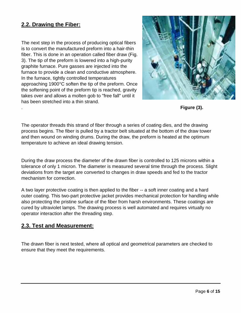
2.2. Drawing the Fiber:
The next step in the process of producing optical fibers
is to convert the manufactured preform into a hair-thin
fiber. This is done in an operation called fiber draw (Fig.
3). The tip of the preform is lowered into a high-purity
graphite furnace. Pure gasses are injected into the
furnace to provide a clean and conductive atmosphere.
In the furnace, tightly controlled temperatures
approaching 1900°C soften the tip of the preform. Once
the softening point of the preform tip is reached, gravity
takes over and allows a molten gob to "free fall" until it
has been stretched into a thin strand.
. Figure (3).
The operator threads this strand of fiber through a series of coating dies, and the drawing
process begins. The fiber is pulled by a tractor belt situated at the bottom of the draw tower
and then wound on winding drums. During the draw, the preform is heated at the optimum
temperature to achieve an ideal drawing tension.
During the draw process the diameter of the drawn fiber is controlled to 125 microns within a
tolerance of only 1 micron. The diameter is measured several time through the process. Slight
deviations from the target are converted to changes in draw speeds and fed to the tractor
mechanism for correction.
A two layer protective coating is then applied to the fiber -- a soft inner coating and a hard
outer coating. This two-part protective jacket provides mechanical protection for handling while
also protecting the pristine surface of the fiber from harsh environments. These coatings are
cured by ultraviolet lamps. The drawing process is well automated and requires virtually no
operator interaction after the threading step.
2.3. Test and Measurement:
The drawn fiber is next tested, where all optical and geometrical parameters are checked to
ensure that they meet the requirements.
Page 7 of 15
3. OPERATION AND MECHANISM
The basic Principle of optic communication:
The optic fiber:
The use of fiber optics in telecommunications and wide area networking has been common for
many years, but more recently fiber optics have become increasingly prevalent in industrial
data communications systems as well. High data rate capabilities, noise rejection and electrical
isolation are just a few of the important characteristics that make fiber optic technology ideal
for use in industrial and commercial systems.
3.1. Fiber Optic Technology:
How does light travel in optic fiber cable?
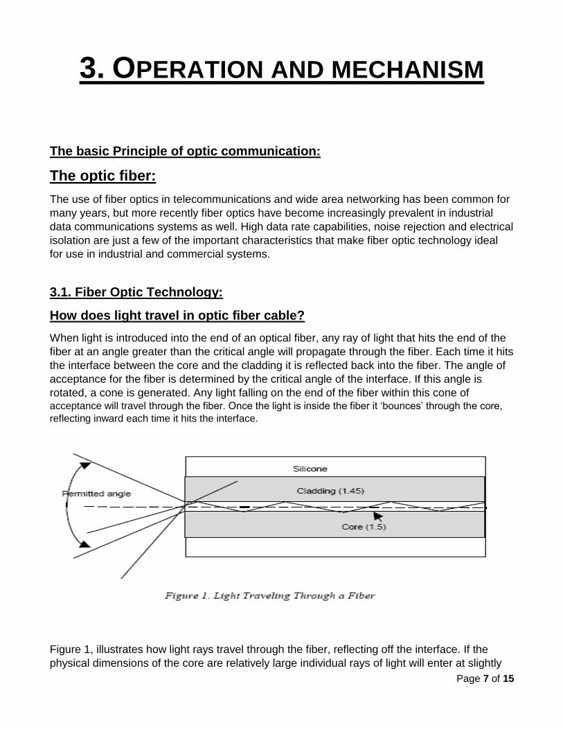
When light is introduced into the end of an optical fiber, any ray of light that hits the end of the
fiber at an angle greater than the critical angle will propagate through the fiber. Each time it hits
the interface between the core and the cladding it is reflected back into the fiber. The angle of
acceptance for the fiber is determined by the critical angle of the interface. If this angle is
rotated, a cone is generated. Any light falling on the end of the fiber within this cone of acceptance will travel through the fiber. Once the light is inside the fiber it ‘bounces’ through the core,
reflecting inward each time it hits the interface.
Figure 1, illustrates how light rays travel through the fiber, reflecting off the interface. If the
physical dimensions of the core are relatively large individual rays of light will enter at slightly
Page 8 of 15
different angles and will reflect at different angles. Since they travel different paths through the
fiber, the distance they travel also varies. As a result they arrive at the receiver at different
times. A pulse signal sent through the fiber will emerge wider than it was sent, deteriorating the
quality of the signal. This is called modal dispersion. Another effect that causes deterioration of
the signal is chromatic dispersion. Chromatic dispersion is caused by light rays of different
wavelengths traveling at different speeds through the fiber. When a series of pulses is sent
through the fiber, modal and chromatic dispersion can eventually cause the pulse to merge
into one long pulse and the data signal is lost.
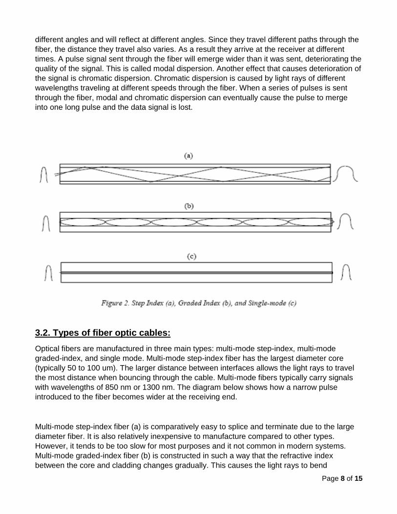
3.2. Types of fiber optic cables:
Optical fibers are manufactured in three main types: multi-mode step-index, multi-mode
graded-index, and single mode. Multi-mode step-index fiber has the largest diameter core
(typically 50 to 100 um). The larger distance between interfaces allows the light rays to travel
the most distance when bouncing through the cable. Multi-mode fibers typically carry signals
with wavelengths of 850 nm or 1300 nm. The diagram below shows how a narrow pulse
introduced to the fiber becomes wider at the receiving end.
Multi-mode step-index fiber (a) is comparatively easy to splice and terminate due to the large
diameter fiber. It is also relatively inexpensive to manufacture compared to other types.
However, it tends to be too slow for most purposes and it not common in modern systems.
Multi-mode graded-index fiber (b) is constructed in such a way that the refractive index
between the core and cladding changes gradually. This causes the light rays to bend
Page 9 of 15
gradually, as well. The resulting pattern of reflections tends to be more uniform and dispersion
is reduced. This provides improved performance for a moderate increase in cost. Graded index
fibers provide wider bandwidth than step-index fibers.
Single-mode fibers (c) give the highest performance of the three types. Manufactured using a
very small diameter fiber (typically 8 um), when light is introduced into the fiber reflections are
kept to a minimum by the dimensions of the core. Light travels virtually straight through the
core and pulses introduced at one end are reproduced at the other end with very little
dispersion. Typically, single-mode fibers carry signals with wavelengths of 1320 nm or 1550
nm. Single-mode fiber is relatively expensive, however, and is more difficult to splice and
terminate since the core must be aligned very accurately.
Single-mode fibers offer much lower attenuation than multi-mode fibers. At typical single-mode
fiber will attenuate a 1310 nm signal less than 0.5 dB per kilometer. A typical multi-mode
graded-index fiber will attenuate the same signal about 3 dB per kilometer. Single-mode fiber
is most often used in applications with high bandwidth requirements over long distances. Some
Ethernet fiber optic equipment can increase distances from two kilometers using multi-mode
fiber to about 70 kilometers over single-mode fiber.
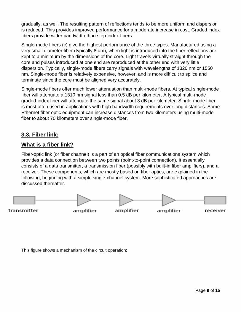
3.3. Fiber link:
What is a fiber link?
Fiber-optic link (or fiber channel) is a part of an optical fiber communications system which
provides a data connection between two points (point-to-point connection). It essentially
consists of a data transmitter, a transmission fiber (possibly with built-in fiber amplifiers), and a
receiver. These components, which are mostly based on fiber optics, are explained in the
following, beginning with a simple single-channel system. More sophisticated approaches are
discussed thereafter.
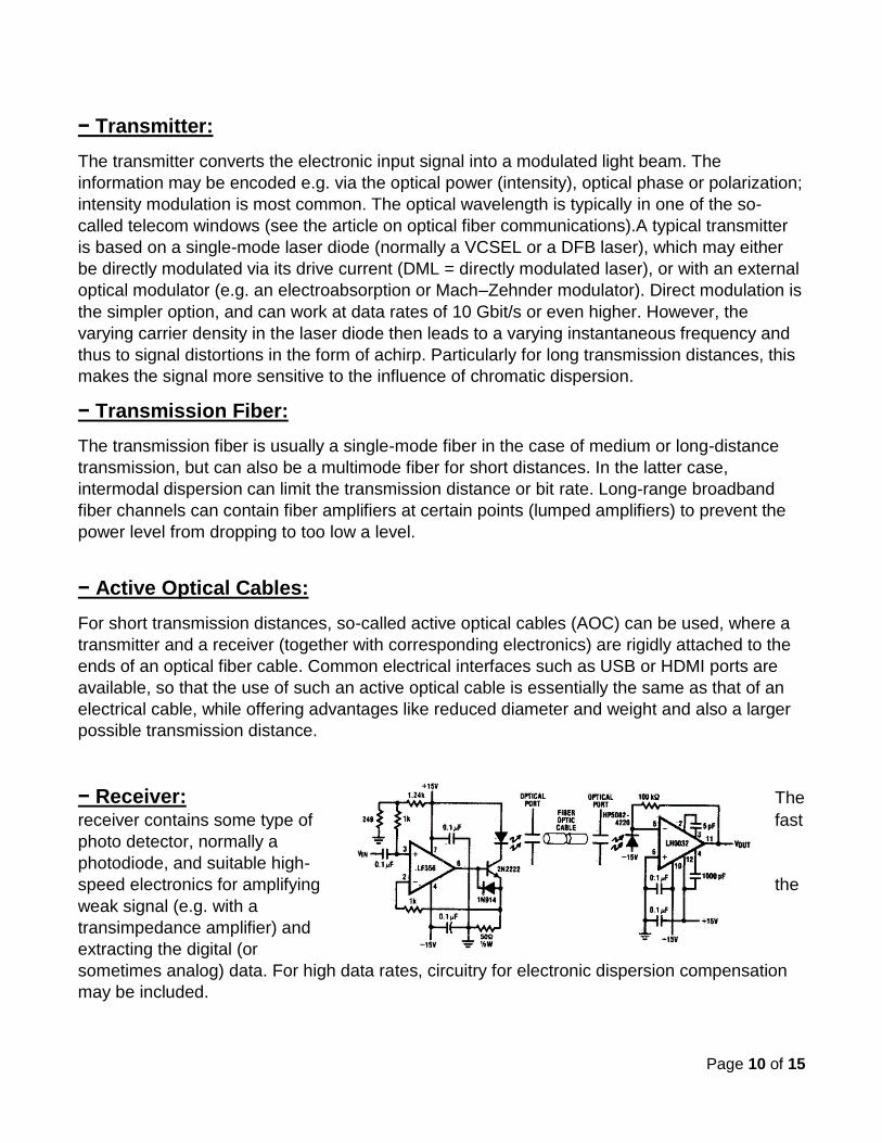
This figure shows a mechanism of the circuit operation:
Page 10 of 15
− Transmitter:
The transmitter converts the electronic input signal into a modulated light beam. The
information may be encoded e.g. via the optical power (intensity), optical phase or polarization;
intensity modulation is most common. The optical wavelength is typically in one of the so-
called telecom windows (see the article on optical fiber communications).A typical transmitter
is based on a single-mode laser diode (normally a VCSEL or a DFB laser), which may either
be directly modulated via its drive current (DML = directly modulated laser), or with an external
optical modulator (e.g. an electroabsorption or Mach–Zehnder modulator). Direct modulation is
the simpler option, and can work at data rates of 10 Gbit/s or even higher. However, the
varying carrier density in the laser diode then leads to a varying instantaneous frequency and
thus to signal distortions in the form of achirp. Particularly for long transmission distances, this
makes the signal more sensitive to the influence of chromatic dispersion.
− Transmission Fiber:
The transmission fiber is usually a single-mode fiber in the case of medium or long-distance
transmission, but can also be a multimode fiber for short distances. In the latter case,
intermodal dispersion can limit the transmission distance or bit rate. Long-range broadband
fiber channels can contain fiber amplifiers at certain points (lumped amplifiers) to prevent the
power level from dropping to too low a level.
− Active Optical Cables:
For short transmission distances, so-called active optical cables (AOC) can be used, where a
transmitter and a receiver (together with corresponding electronics) are rigidly attached to the
ends of an optical fiber cable. Common electrical interfaces such as USB or HDMI ports are
available, so that the use of such an active optical cable is essentially the same as that of an
electrical cable, while offering advantages like reduced diameter and weight and also a larger
possible transmission distance.
− Receiver: The
receiver contains some type of fast
photo detector, normally a
photodiode, and suitable high-
speed electronics for amplifying the
weak signal (e.g. with a
transimpedance amplifier) and
extracting the digital (or
sometimes analog) data. For high data rates, circuitry for electronic dispersion compensation
may be included.
Page 11 of 15
4. Fiber Optic communication Fiber-optic communication is a method of transmitting information from one place to another by
sending pulses of light through an optical fiber. This process consists of 3 stages, transmitting
the light wave, receiving this wave and the movement of the waves between these 2 stages
where amplification occur.
4.1 Transmitter:
There are 2 main types of transmitters, light emitting diodes (LEDs) and laser diodes.
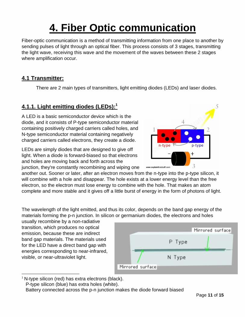
4.1.1. Light emitting diodes (LEDs):1
A LED is a basic semiconductor device which is the
diode, and it consists of P-type semiconductor material
containing positively charged carriers called holes, and
N-type semiconductor material containing negatively
charged carriers called electrons, they create a diode.
LEDs are simply diodes that are designed to give off
light. When a diode is forward-biased so that electrons
and holes are moving back and forth across the
junction, they're constantly recombining and wiping one
another out. Sooner or later, after an electron moves from the n-type into the p-type silicon, it
will combine with a hole and disappear. The hole exists at a lower energy level than the free
electron, so the electron must lose energy to combine with the hole. That makes an atom
complete and more stable and it gives off a little burst of energy in the form of photons of light.
The wavelength of the light emitted, and thus its color, depends on the band gap energy of the
materials forming the p-n junction. In silicon or germanium diodes, the electrons and holes
usually recombine by a non-radiative
transition, which produces no optical
emission, because these are indirect
band gap materials. The materials used
for the LED have a direct band gap with
energies corresponding to near-infrared,
visible, or near-ultraviolet light.
1 N-type silicon (red) has extra electrons (black).
P-type silicon (blue) has extra holes (white). Battery connected across the p-n junction makes the diode forward biased
Page 12 of 15
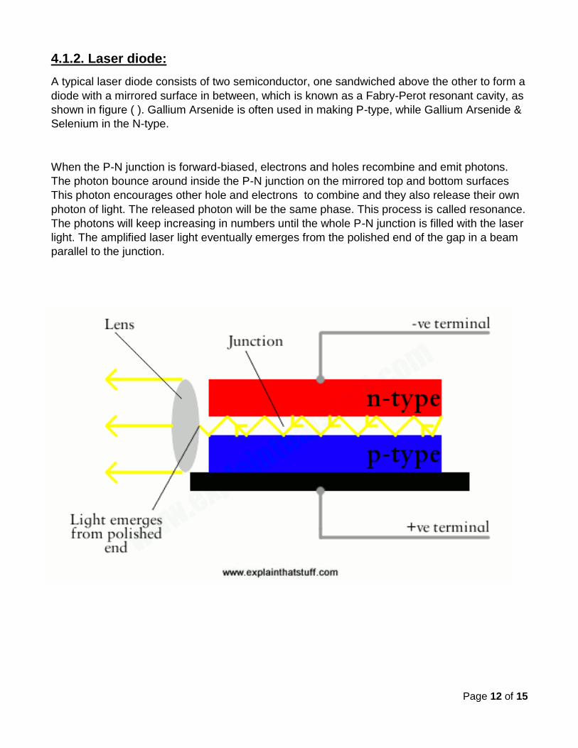
4.1.2. Laser diode:
A typical laser diode consists of two semiconductor, one sandwiched above the other to form a
diode with a mirrored surface in between, which is known as a Fabry-Perot resonant cavity, as
shown in figure ( ). Gallium Arsenide is often used in making P-type, while Gallium Arsenide &
Selenium in the N-type.
When the P-N junction is forward-biased, electrons and holes recombine and emit photons.
The photon bounce around inside the P-N junction on the mirrored top and bottom surfaces
This photon encourages other hole and electrons to combine and they also release their own
photon of light. The released photon will be the same phase. This process is called resonance.
The photons will keep increasing in numbers until the whole P-N junction is filled with the laser
light. The amplified laser light eventually emerges from the polished end of the gap in a beam
parallel to the junction.
Page 13 of 15
4.2. Receivers:
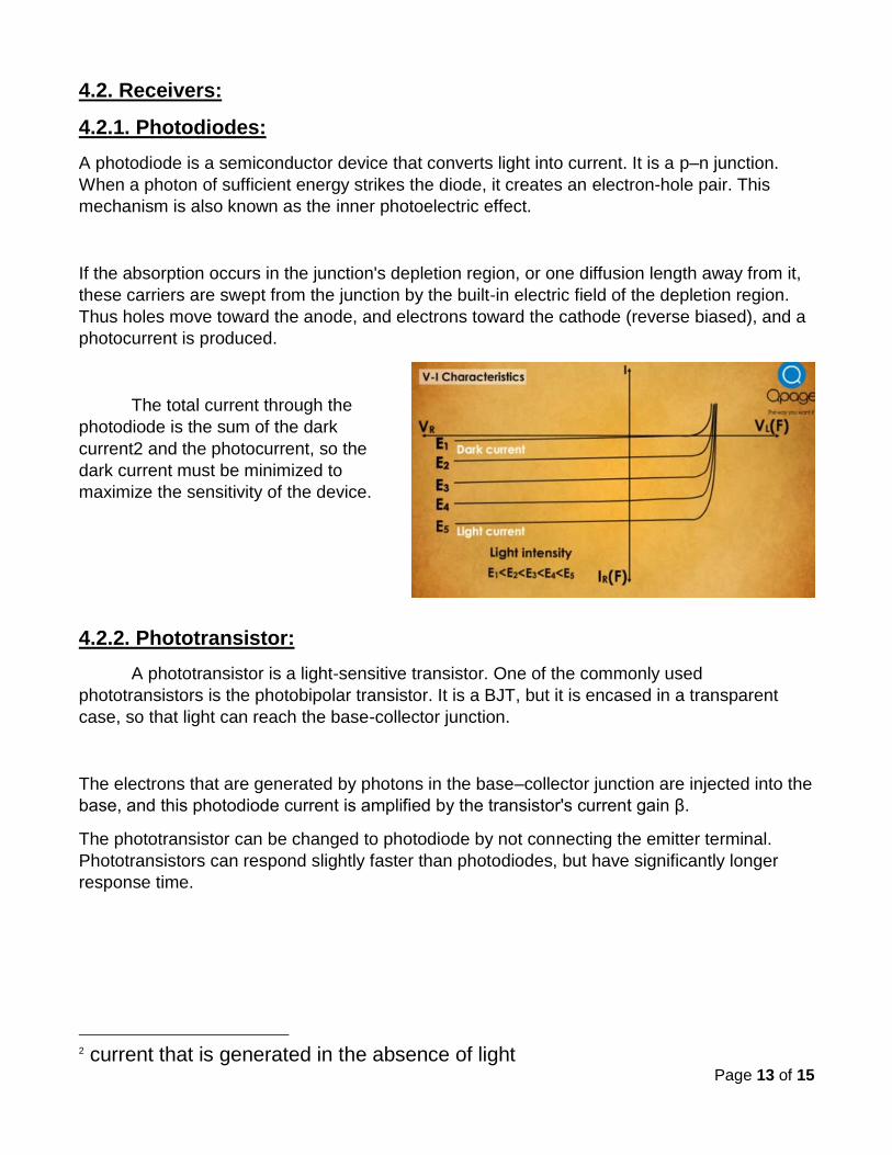
4.2.1. Photodiodes:
A photodiode is a semiconductor device that converts light into current. It is a p–n junction.
When a photon of sufficient energy strikes the diode, it creates an electron-hole pair. This
mechanism is also known as the inner photoelectric effect.
If the absorption occurs in the junction's depletion region, or one diffusion length away from it,
these carriers are swept from the junction by the built-in electric field of the depletion region.
Thus holes move toward the anode, and electrons toward the cathode (reverse biased), and a
photocurrent is produced.
The total current through the
photodiode is the sum of the dark
current2 and the photocurrent, so the
dark current must be minimized to
maximize the sensitivity of the device.
4.2.2. Phototransistor:
A phototransistor is a light-sensitive transistor. One of the commonly used
phototransistors is the photobipolar transistor. It is a BJT, but it is encased in a transparent
case, so that light can reach the base-collector junction.
The electrons that are generated by photons in the base–collector junction are injected into the
base, and this photodiode current is amplified by the transistor's current gain β.
The phototransistor can be changed to photodiode by not connecting the emitter terminal.
Phototransistors can respond slightly faster than photodiodes, but have significantly longer
response time.
2 current that is generated in the absence of light
Page 14 of 15
4.3. Optical amplifier:
An optical amplifier is a device that amplifies an optical signal directly, without the need
to first convert it to an electrical signal. Optical amplifiers are important in optical
communication, when the signal decays due to long distance transmission light is passed
through an optical amplifier to reinforce the signal. There are several different physical
mechanisms that can be used to amplify a light signal for example:
Doped fiber amplifiers:
Doped fiber amplifiers (DFAs) are optical amplifiers that use a doped optical fiber as a gain
medium to amplify an optical signal. The most common example is the Erbium Doped Fiber
Amplifier (EDFA), where the core of a silica fiber is doped with trivalent erbium ions.
Amplification is achieved by stimulated emission of photons from dopant ions in the doped
fiber. The pump laser excites ions into a higher energy from where they can decay via
stimulated emission of a photon at the signal wavelength back to a lower energy level.
Basic principle of EDFA:
A relatively high-powered beam of light is mixed with the input signal using a wavelength
selective coupler. The input signal and the excitation light must be at significantly different
wavelengths. The mixed light is guided into a section of fiber with erbium ions included in the
core. This high-powered light beam excites the erbium ions to their higher-energy state. When
the photons belonging to the signal at a different wavelength from the pump light meet the
excited erbium atoms, the erbium atoms give up some of their energy to the signal and return
to their lower-energy state. A significant point is that the erbium gives up its energy in the form
of additional photons which are exactly in the same phase and direction as the signal being
amplified. So the signal is amplified along its direction of travel only. Thus all of the additional
signal power is guided in the same fiber mode as the incoming signal.
There is usually an isolator placed at the output to prevent reflections returning from the
attached fiber. Such reflections disrupt amplifier operation and in the extreme case can cause
the amplifier to become a laser. The erbium doped amplifier is a high gain amplifier

Page 15 of 15
5. References: http://imcnetworks.com/overview-fiber-optic-technology/
http://www.next.gr/sens-detectors/optical/fiber-optic-link-
l12693.html
http://www.rp-photonics.com/fiber_optic_links.html
http://en.wikipedia.org/wiki/Optical_fiber#Manufacturing
http://www.rp-photonics.com/fiber_amplifiers.html
http://en.wikipedia.org/wiki/Optical_amplifier
http://en.wikipedia.org/wiki/Photodiode
http://hyperphysics.phy-
astr.gsu.edu/hbase/electronic/photdet.html
http://www.explainthatstuff.com/diodes.html
http://www.explainthatstuff.com/semiconductorlaserdiod
es.html
http://en.wikipedia.org/wiki/Light-emitting_diode
http://en.wikipedia.org/wiki/Laser_diode