Embed Size (px)
Citation preview
International Journal of Computer Science and Telecommunications [Volume 2, Issue 6, September 2011] 64
Journal Homepage: www.ijcst.org
Abd El–Naser A. Mohamed1, Hamdy A. Sharshar2,
Ahmed Nabih Zaki Rashed3*, and Sakr A. S. Hanafy
4
1,2,3,4Electronics and Electrical Communications Engineering Department
Faculty of Electronic Engineering, Menouf 32951, Menoufia University, Egypt 3*E-mail: [email protected]
Abstract— This paper has proposed two different fiber
structures for dispersion management are investigated, where
two types of fabrication material link of single mode fiber
made of pure silica and plastic optical fibers are suggested,
where one successive segment of single mode fiber made of
silica fibers is suggested to be employed periodically in the
short transmission systems namely different relative refractive
index differences (∆∆∆∆n). As well as we have presented the total transmission characteristics of both materials based optical
links under the thermal effect of to be processed to handle both
transmission lengths and bit rates per channel for cables of
multi links over wide range of the affecting parameters. Within
maximum time division multiplexing (MTDM) transmission
technique, we have estimated both the transmission bit rate
and capacity distance product per channels for both materials
based optical links under study. The bit rates are studied
within thermal and dispersion sensitivity effects of the
refractive-index of the materials based optical links are taken
into account to present the effects on the performance of
optical fiber cable links. Dispersion characteristics and
dispersion management are deeply studied where two types of
optical fiber cable link materials are used. A new novel
technique of chromatic dispersion management in optical
single mode fiber is introduced to facilitate the design of the
highest and the best transmission performance of bit rates in
advanced local area optical communication networks.
Index Terms— Single Mode Fibers (SMFs), Dispersion
Management, High Data Rate, Optical Link Design and
Thermal Effects
I. INTRODUCTION
PTICAL fiber communications technology has been
extensively employed and deployed in global
communications networks and throughout terrestrial
systems; from fiber to the home schemes in several
countries to internetworking between countries and major
cities [1]. The enormous bandwidth of optical fibers and
advancement of 0optical communications technology
together with the direct photon to photon amplification
make possible several innovative configurations of optical
transmission systems and distribution networks. Current
deployment of optical signals over single mode optical
fibers in the filed are only based on single channels either at
1310 nm or 1550 nm windows [2], except in some field trail
systems and networks. It is essential that these enormous
bandwidth regions should be used extensively. Intense
investigation and experiments of ultra-long and ultra-high
speed optical communication systems have been carried out
together with interests in the multiplexing of optical carriers
in the same fiber channel; the wavelength division
multiplexing techniques have been used as the unique
technology [3].
Current conventional amplification and dispersion
compensation and management have assumed great
importance as there are the main impairing factors for
achieving repeater less transmission distance in excess of
100 km over standard single mode fibers. One of the earliest
techniques suggested to reduce the dispersion at 1550 nm
band was to tailor the refractive index profile of a single
mode fiber in such a way that its zero dispersion wavelength
is shifted from the conventional 1310 nm window to a round
1550 nm [4]. These fibers, called dispersion shifted fibers
(DSF) through appeared promising for a while, but, were
found to be unusable in dense wavelength division
multiplexing (DWDM) link due to the fact that operating a
fiber with near zero dispersion is known to introduce
nonlinear effects like four wave mixing (FWM) [5]. It is
known that FWM effect can be greatly reduced by allowing
a small but finite local dispersion all along a DWDM link.
This task could be fulfilled either through dispersion
management (i.e. by combing alternate lengths of positive
and negative dispersion fibers [6]) or by employing so called
nonzero dispersion shifted fibers. Which is designed to leave
a small residual average dispersion of 2.6 ps/km to omit
nonlinear propagation effects in the single mode fiber?
Chromatic dispersion is a linear effect and inserting a
component with opposite sign could greatly reduce its
detrimental effect in G.652 fibers at the 1550 nm band. Out
of the several different technique that have been proposed in
the literature, the ones which seem to hold immediate
promise could be classified as dispersion compensating fiber
(DCF)[7], chirped fiber Bragg grating (FBG) [8],[9], high
order mode (HOM) fibers[10]. In chirped grating the optical
pitch (product between the grating period and the mode
effective index) varies along length of the FBG. As a result,
resonant reflection frequency of the FBG becomes a
function of position along length of FBG. Thus, each
frequency component of a propagating pulse is reflected
from a different point along length of chirped FBG. This is
depending on the sign of the chirp; a chirped FBG could
impart either a positive or negative dispersion to a
propagating pulse [11]. Since, dispersion compensation is
achieved or reflection to access the dispersion corrected
pulse. And optical circulator or a fiber coupler is required as
an additional component with associated insertion loss.
O
High Transmission Data Rate of Plastic Optical Fibers
over Silica Optical Fibers Based Optical Links for Short
Transmission Ranges ISSN 2047-3338
Ahmed Nabih Zaki Rashed et al. 65
Furthermore, errors in the chirped phase mask periodicity
could lead to ripples in group delay with wavelength [12].
In the present study, plastic optical fibers (POFs) are the
most promising solution for the "last 100 m to 1000 m" in
high data communications over conventional silica optical
fibers for short transmission ranges. The combine the
inherent benefits of all optical fibers such as high
bandwidth, total electromagnetic immunity with additionally
amazing simplicity in handling. These benefits make POFs
attractive for a wide variety of applications for short
transmission range media.
II. MODELING BASICS AND ANALYSIS
A. Simplified Dispersion Model Analysis
The standard single mode fiber link cable is made of both
materials under study which the investigation of the spectral
variations of the waveguide refractive-index, n requires
empirical equation under the form [13]:
26
2
25
24
2
23
22
2
212 1
A
A
A
A
A
An
−+
−+
−+=
λ
λ
λ
λ
λ
λ (1)
The empirical equation coefficients as a function of
ambient temperature and room temperature as:
A1S=0.691663, A2S=0.03684043 (T/T0)2, A3S=0.4079426,
A4S=0.0116241 (T/T0)2, A5S=0.8974749, A6S= 84.76543
(T/T0)2. Where T is ambient temperature in K, and T0 is the
room temperature and is considered as 300 K. Second
differentiation of empirical equation w. r. t operating
wavelength λ as in Ref. [14]. For the plastic fiber material, the coefficients of the Sellmeier equation and refractive-
index variation with ambient temperature are given as: A1P=
0.4963, A2P= 0.6965 (T/T0)2, A3P= 0.3223, A4P= 0.718
(T/T0)2, A5P= 0.1174, and A6P= 9.237. The maximum bit
rates are determined by numerous factors, including the
signal modulation rate, the transmission bandwidth through
the transmission media, and the response time of the
optoelectronic devices. The pulse broadening of grating-
based multiplexing communication system imposes inherent
limitations on the data transmission bit rates. The total
chromatic dispersion in standard single mode fiber that
limits the bit rates in system based ultra multiplexing
communication system can be calculated as follows [15]:
( ) kmnmnMMD wdmdt .sec/,+−= (2)
Where Mmd is the material dispersion coefficient in
nsec/nm.km, Mwd is the waveguide dispersion coefficient in
nsec/nm.km, The material dispersion coefficient is given as:
,2 2
2
2
2
∆−−=
λ
λ
λ
λ
d
nd
cd
nd
cM smd (3)
The waveguide dispersion coefficient is given by:
( ) ,VFc
nnM
scladdingwd
∆−=
λ (4)
Where n is the refractive index of the cladding material, c is
the velocity of light (3x10⁸ m/sec), ∆n is the relative
refractive-index difference, λs is the optical signal
wavelength, F (V) is a function of V number or normalized
frequency. Based on the work [16], they designed the
function F (V) is a function of V as follows:
( ) 5432 48.184.445.1398.638.1 VVVVVVF −−+−= (5)
When they are employing V-number in the range of (0 ≤ V ≤ 1.15) yields the above expression. In our simulation model
design, we are taking into account V-number as unity to
emphasis single mode operation. Where the total dispersion
coefficient (nsec/nm.km) in the plastic fiber link is given by:
( ) ,PWD mdt += (6)
In which both material and profile dispersions were taken
into account as Wmd and P respectively [16]:
( )5.0
112
223
2
22
+
∆
−
−=
αα
λ
λλ
λCnN
d
nd
cd
dn
cWmd (7)
21
221
23
2
2
2
+×
+
−−
∆=
αα
αεα
λcnN
P (8)
Where N1 is the group index for the mode which is given by:
,1 λλd
dnnN −= (9)
Where C1 is a constant related to index exponent and profile
dispersion and is given by:
,2
21 +
−−=
αεα
C (10)
Where α is the index exponent, and ε is the profile dispersion parameter and is given by:
,2
1 nN
n
∆−=
λε (11)
B. MTDM Transmission Technique
To achieve a high data transmission bit rate in the
telecommunication field is the goal of wavelength division
multiplexing technology. The maximum bit rates are
determined by numerous factors, including the signal
modulation rate, the transmission bandwidth through the
transmission media, and the response time of the
optoelectronic devices. In ultra multiplexing communication
system is simply one part of the transmission regime.
Therefore, the total pulse broadening due to the first order
dispersion in standard single mode fiber (SSMF) that limits
the bit rates in system based multiplexing communication
system can be expressed as [17]:
kmnmnLDt .sec/,.. λτ ∆=∆ (12)
Where ∆λ is the spectral linewidth of optical source in nm, and L is the transmission link length in km. The pulse
broadening of grating based multiplexing communication
system imposes inherent limitations on the transmission bit
rates. Then the MTDM transmission bit rate per channel is
given by [18]:
channelGbitBrmc sec//,25.0
4
1
ττ ∆=
∆= (13)
Then the MTDM transmission bit rate per link is given as:
linkGbitN
B linkrml sec//,
.25.0
τ∆= (14)
The available MTDM transmitted bit rate Brm is compared
as the fiber cable length, L, and consequently the MTDM
product Prmc per channel is computed as [19]:
sec/.,. kmGbitLBP rmcrmc = (15)
Also, in the same way, the MTDM product Prml per link is
computed as the following expression:
sec/.,. kmGbitLBP rmlrml = (16)
As well as the transmitted signal bandwidth within single
mode fibers based optical link can be [20]:
,44.0
. .L
WB Sig τ∆= (17)
International Journal of Computer Science and Telecommunications [Volume 2, Issue 6, September 2011] 66
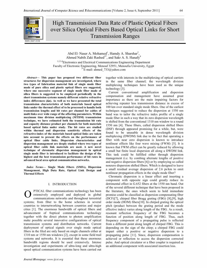
Fig. 1. Sensitivity concept analysis
The thermal sensitivity is the guide of the measurement
the relative variations of the output (response, effect) and
the relative variations of the input (Excitation, cause) as
shown in Fig. 1:
The MTDM bit rate within thermal and dispersion
sensitivity coefficients are taken into account as criteria of a
complete comparison between silica and plastic fibers for
based link design and are given by [21]:
dT
dB
B
TS rm
rm
BTrm .= , (18)
The transmission bit rate thermal penalty as a function of
temperature variations can be expressed as [22]:
[ ] ,)(/)()( 00 TBTBTBP rmrmrmT −= (19)
III. SIMULATION RESULTS AND PERFORMANCE
ANALYSIS
We have been investigated the high data transmission bit
rates of plastic optical fibers over silica optical fibers for
short transmission applications in the interval of 1.3 µm to
1.65 µm under the set of affecting parameters at temperature
range varies from 300 K to 330 K. The following set of the
numerical data of system model design are employed to
obtain transmission bit rate and capacity-distance product
per channel as follows: 1.3 ≤ λs, central optical signal
wavelength, µm ≤ 1.65, spectral line width of the optical
source, Index exponent g=2.5, ∆λ= 0.1 nm, 0.1 ≤ transmission link length, L, km ≤ 1, and 0.0275 ≤ ∆n,
relative refractive-index difference ≤ 0.0495. At the
assumed set of operating parameters {optical signal
wavelength λs, ambient temperature and refractive
refractive-index difference}, both the effective performance
of plastic and silica fibers are processed based on both the
transmission bit rate and capacity-distance product either per
link or per channel. The transmitted bit-rate per optical
channel is also a special criterion for comparison for
different fiber link materials of plastic and silica fibers.
Based on the clarified variations in Figs. (2-22), the
following facts are assured:
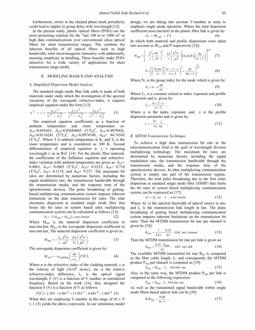
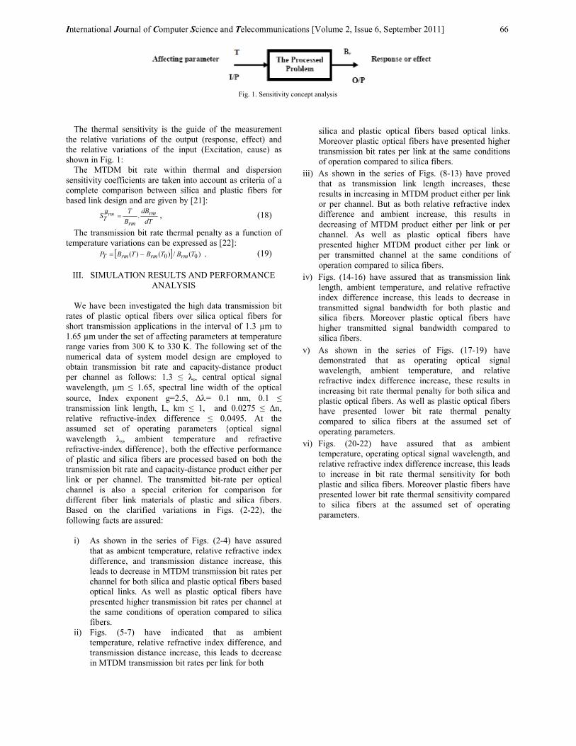
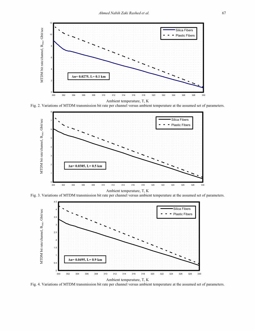
i) As shown in the series of Figs. (2-4) have assured
that as ambient temperature, relative refractive index
difference, and transmission distance increase, this
leads to decrease in MTDM transmission bit rates per
channel for both silica and plastic optical fibers based
optical links. As well as plastic optical fibers have
presented higher transmission bit rates per channel at
the same conditions of operation compared to silica
fibers.
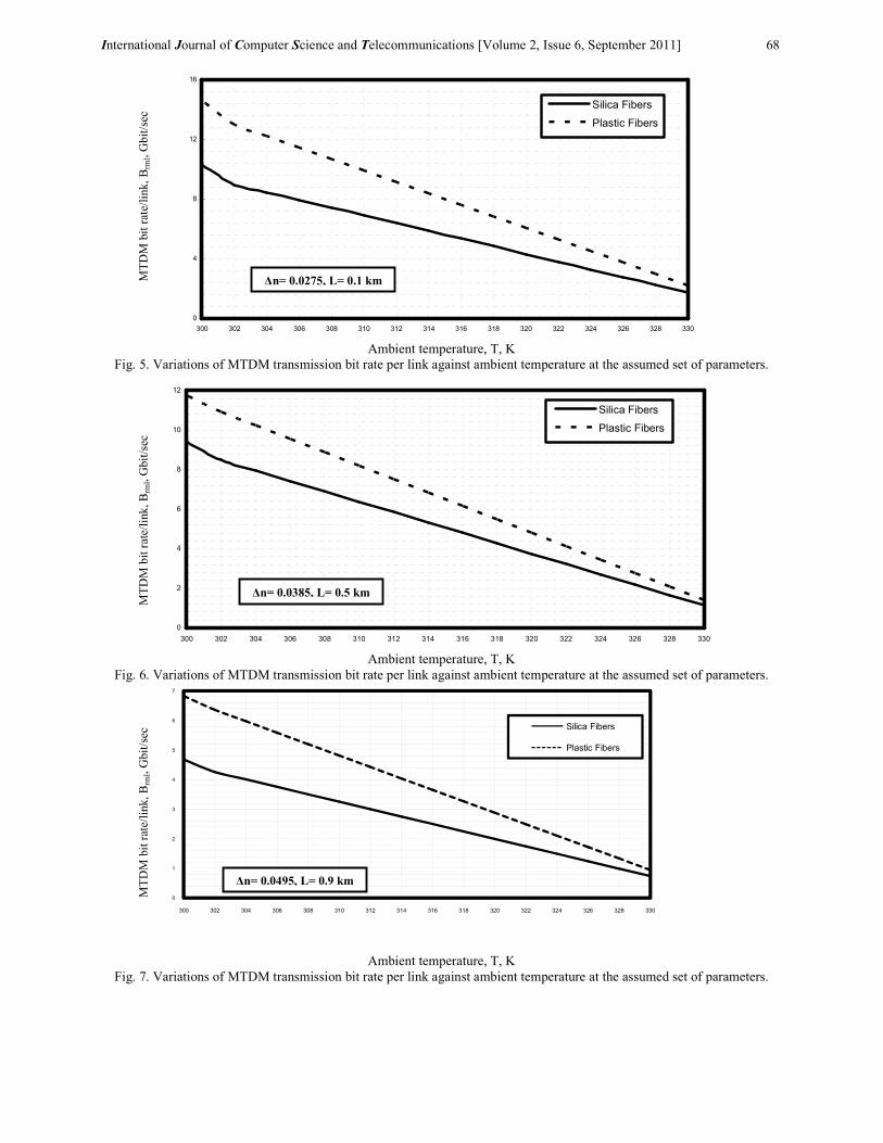
ii) Figs. (5-7) have indicated that as ambient
temperature, relative refractive index difference, and
transmission distance increase, this leads to decrease
in MTDM transmission bit rates per link for both
silica and plastic optical fibers based optical links.
Moreover plastic optical fibers have presented higher
transmission bit rates per link at the same conditions
of operation compared to silica fibers.
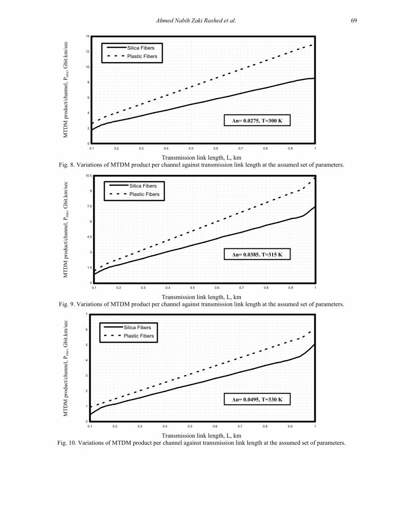
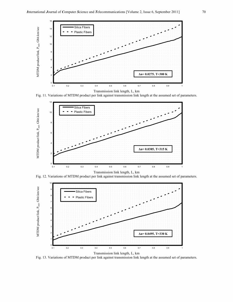
iii) As shown in the series of Figs. (8-13) have proved
that as transmission link length increases, these
results in increasing in MTDM product either per link
or per channel. But as both relative refractive index
difference and ambient increase, this results in
decreasing of MTDM product either per link or per
channel. As well as plastic optical fibers have
presented higher MTDM product either per link or
per transmitted channel at the same conditions of
operation compared to silica fibers.
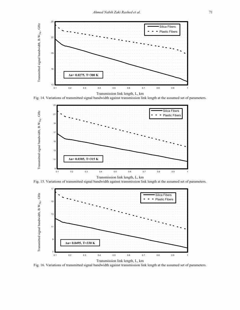
iv) Figs. (14-16) have assured that as transmission link
length, ambient temperature, and relative refractive
index difference increase, this leads to decrease in
transmitted signal bandwidth for both plastic and
silica fibers. Moreover plastic optical fibers have
higher transmitted signal bandwidth compared to
silica fibers.
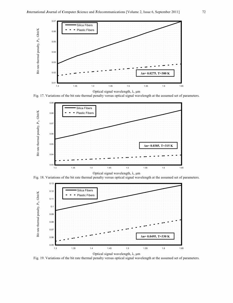
v) As shown in the series of Figs. (17-19) have
demonstrated that as operating optical signal
wavelength, ambient temperature, and relative
refractive index difference increase, these results in
increasing bit rate thermal penalty for both silica and
plastic optical fibers. As well as plastic optical fibers
have presented lower bit rate thermal penalty
compared to silica fibers at the assumed set of
operating parameters.
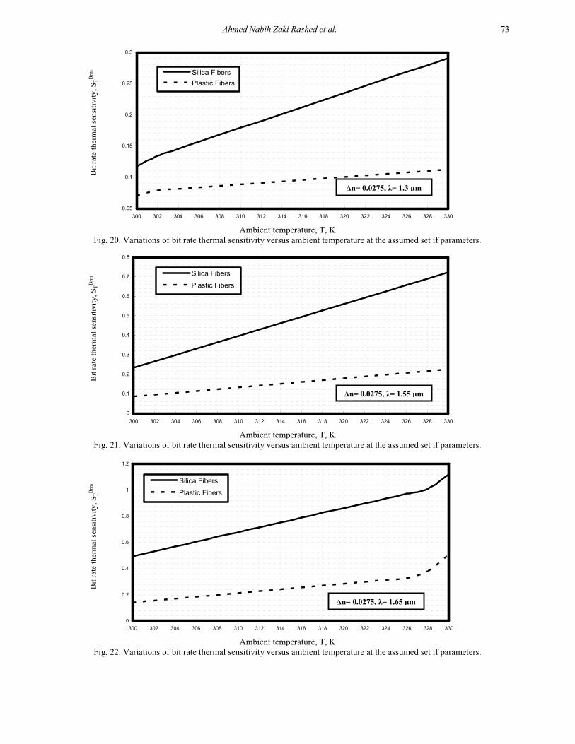
vi) Figs. (20-22) have assured that as ambient
temperature, operating optical signal wavelength, and
relative refractive index difference increase, this leads
to increase in bit rate thermal sensitivity for both
plastic and silica fibers. Moreover plastic fibers have
presented lower bit rate thermal sensitivity compared
to silica fibers at the assumed set of operating
parameters.
Ahmed Nabih Zaki Rashed et al. 67
0
2
4
6
8
10
12
300 302 304 306 308 310 312 314 316 318 320 322 324 326 328 330
Silica Fibers
Plastic Fibers
Ambient temperature, T, K
Fig. 2. Variations of MTDM transmission bit rate per channel versus ambient temperature at the assumed set of parameters.
0
1
2
3
4
5
6
7
8
300 302 304 306 308 310 312 314 316 318 320 322 324 326 328 330
Silica Fibers
Plastic Fibers
Ambient temperature, T, K
Fig. 3. Variations of MTDM transmission bit rate per channel versus ambient temperature at the assumed set of parameters.
0
0.5
1
1.5
2
2.5
3
3.5
4
4.5
300 302 304 306 308 310 312 314 316 318 320 322 324 326 328 330
Silica Fibers
Plastic Fibers
Ambient temperature, T, K
Fig. 4. Variations of MTDM transmission bit rate per channel versus ambient temperature at the assumed set of parameters.
MTDM bit rate/channel, Brmc, Gbit/sec
∆n= 0.0275, L= 0.1 km
MTDM bit rate/channel, Brmc, Gbit/sec
∆n= 0.0385, L= 0.5 km
MTDM bit rate/channel, Brmc, Gbit/sec
∆n= 0.0495, L= 0.9 km
International Journal of Computer Science and Telecommunications [Volume 2, Issue 6, September 2011] 68
0
4
8
12
16
300 302 304 306 308 310 312 314 316 318 320 322 324 326 328 330
Silica Fibers
Plastic Fibers
Ambient temperature, T, K
Fig. 5. Variations of MTDM transmission bit rate per link against ambient temperature at the assumed set of parameters.
0
2
4
6
8
10
12
300 302 304 306 308 310 312 314 316 318 320 322 324 326 328 330
Silica Fibers
Plastic Fibers
Ambient temperature, T, K
Fig. 6. Variations of MTDM transmission bit rate per link against ambient temperature at the assumed set of parameters.
0
1
2
3
4
5
6
7
300 302 304 306 308 310 312 314 316 318 320 322 324 326 328 330
Silica Fibers
Plastic Fibers
Ambient temperature, T, K
Fig. 7. Variations of MTDM transmission bit rate per link against ambient temperature at the assumed set of parameters.
MTDM bit rate/link, Brml, Gbit/sec
MTDM bit rate/link, Brml, Gbit/sec
MTDM bit rate/link, Brml, Gbit/sec
∆n= 0.0495, L= 0.9 km
∆n= 0.0385, L= 0.5 km
∆n= 0.0275, L= 0.1 km
Ahmed Nabih Zaki Rashed et al. 69
0
2
4
6
8
10
12
14
0.1 0.2 0.3 0.4 0.5 0.6 0.7 0.8 0.9 1
Silica Fibers
Plastic Fibers
Transmission link length, L, km
Fig. 8. Variations of MTDM product per channel against transmission link length at the assumed set of parameters.
0
1.5
3
4.5
6
7.5
9
10.5
0.1 0.2 0.3 0.4 0.5 0.6 0.7 0.8 0.9 1
Silica Fibers
Plastic Fibers
Transmission link length, L, km
Fig. 9. Variations of MTDM product per channel against transmission link length at the assumed set of parameters.
0
1
2
3
4
5
6
7
0.1 0.2 0.3 0.4 0.5 0.6 0.7 0.8 0.9 1
Silica Fibers
Plastic Fibers
Transmission link length, L, km
Fig. 10. Variations of MTDM product per channel against transmission link length at the assumed set of parameters.
MTDM product/channel, Prmc, Gbit.km/sec
MTDM product/channel, Prmc, Gbit.km/sec
MTDM product/channel, Prmc, Gbit.km/sec
∆n= 0.0275, T=300 K
∆n= 0.0385, T=315 K
∆n= 0.0495, T=330 K
International Journal of Computer Science and Telecommunications [Volume 2, Issue 6, September 2011] 70
0
2
4
6
8
10
12
14
16
0.1 0.2 0.3 0.4 0.5 0.6 0.7 0.8 0.9 1
Silica Fibers
Plastic Fibers
Transmission link length, L, km
Fig. 11. Variations of MTDM product per link against transmission link length at the assumed set of parameters.
0
2
4
6
8
10
12
0.1 0.2 0.3 0.4 0.5 0.6 0.7 0.8 0.9 1
Silica Fibers
Plastic Fibers
Transmission link length, L, km
Fig. 12. Variations of MTDM product per link against transmission link length at the assumed set of parameters.
0
1
2
3
4
5
6
7
8
9
10
0.1 0.2 0.3 0.4 0.5 0.6 0.7 0.8 0.9 1
Silica Fibers
Plastic Fibers
Transmission link length, L, km
Fig. 13. Variations of MTDM product per link against transmission link length at the assumed set of parameters.
MTDM product/link, Prml, Gbit.km/sec
MTDM product/link, Prml, Gbit.km/sec
MTDM product/link, Prml, Gbit.km/sec
∆n= 0.0275, T=300 K
∆n= 0.0385, T=315 K
∆n= 0.0495, T=330 K
Ahmed Nabih Zaki Rashed et al. 71
13
16
19
22
25
0.1 0.2 0.3 0.4 0.5 0.6 0.7 0.8 0.9 1
Silica Fibers
Plastic Fibers
Transmission link length, L, km
Fig. 14. Variations of transmitted signal bandwidth against transmission link length at the assumed set of parameters.
9
11
13
15
17
19
21
23
0.1 0.2 0.3 0.4 0.5 0.6 0.7 0.8 0.9 1
Silica Fibers
Plastic Fibers
Transmission link length, L, km
Fig. 15. Variations of transmitted signal bandwidth against transmission link length at the assumed set of parameters.
7
9
11
13
15
17
0.1 0.2 0.3 0.4 0.5 0.6 0.7 0.8 0.9 1
Silica Fibers
Plastic Fibers
Transmission link length, L, km
Fig. 16. Variations of transmitted signal bandwidth against transmission link length at the assumed set of parameters.
Transmitted signal bandwidth, B.W
Sig., GHz
Transmitted signal bandwidth, B.W
Sig., GHz
Transmitted signal bandwidth, B.W
Sig., GHz
∆n= 0.0275, T=300 K
∆n= 0.0385, T=315 K
∆n= 0.0495, T=330 K
International Journal of Computer Science and Telecommunications [Volume 2, Issue 6, September 2011] 72
0.01
0.02
0.03
0.04
0.05
0.06
0.07
1.3 1.35 1.4 1.45 1.5 1.55 1.6 1.65
Silica Fibers
Plastic Fibers
Optical signal wavelength, λ, µm
Fig. 17. Variations of the bit rate thermal penalty versus optical signal wavelength at the assumed set of parameters.
0.03
0.04
0.05
0.06
0.07
0.08
0.09
1.3 1.35 1.4 1.45 1.5 1.55 1.6 1.65
Silica Fibers
Plastic Fibers
Optical signal wavelength, λ, µm
Fig. 18. Variations of the bit rate thermal penalty versus optical signal wavelength at the assumed set of parameters.
0.05
0.06
0.07
0.08
0.09
0.1
0.11
0.12
0.13
1.3 1.35 1.4 1.45 1.5 1.55 1.6 1.65
Silica Fibers
Plastic Fibers
Optical signal wavelength, λ, µm
Fig. 19. Variations of the bit rate thermal penalty versus optical signal wavelength at the assumed set of parameters.
Bit rate thermal penalty, PT, Gbit/K
Bit rate thermal penalty, PT, Gbit/K
Bit rate thermal penalty, PT, Gbit/K
∆n= 0.0275, T=300 K
∆n= 0.0385, T=315 K
∆n= 0.0495, T=330 K
Ahmed Nabih Zaki Rashed et al. 73
0.05
0.1
0.15
0.2
0.25
0.3
300 302 304 306 308 310 312 314 316 318 320 322 324 326 328 330
Silica Fibers
Plastic Fibers
Ambient temperature, T, K
Fig. 20. Variations of bit rate thermal sensitivity versus ambient temperature at the assumed set if parameters.
0
0.1
0.2
0.3
0.4
0.5
0.6
0.7
0.8
300 302 304 306 308 310 312 314 316 318 320 322 324 326 328 330
Silica Fibers
Plastic Fibers
Ambient temperature, T, K
Fig. 21. Variations of bit rate thermal sensitivity versus ambient temperature at the assumed set if parameters.
0
0.2
0.4
0.6
0.8
1
1.2
300 302 304 306 308 310 312 314 316 318 320 322 324 326 328 330
Silica Fibers
Plastic Fibers
Ambient temperature, T, K
Fig. 22. Variations of bit rate thermal sensitivity versus ambient temperature at the assumed set if parameters.
Bit rate thermal sensitivity, STBrm
Bit rate thermal sensitivity, STBrm
Bit rate thermal sensitivity, STBrm
∆n= 0.0275, λ= 1.3 µm
∆n= 0.0275, λ= 1.55 µm
∆n= 0.0275, λ= 1.65 µm
International Journal of Computer Science and Telecommunications [Volume 2, Issue 6, September 2011] 74
IV. CONCLUSIONS
In a summary, we have presented high transmission data
rates of plastic optical fibers over conventional silica fibers
based optical links for short transmission applications.
Plastic optical fibers can be designed on window platform so
that users can design or select appropriate fiber types which
are standard single mode optical fibers, dispersion shifted
fibers, dispersion flatten fibers and multi layer refractive
index profile fibers. It is theoretically found that the
increased ambient temperature, relative refractive index
difference, and transmission link length, this leads to the
decreased of MTDM transmission bit rates either per link or
per channel for both plastic and silica fibers. As well as the
increased transmission link length, this results in the
increasing of MTDM product either per link or per channel
for both materials based optical links under study. But the
increased of both ambient temperature and relative
refractive index difference, this leads to the decreased of
MTDM product either per link or per channel for both
materials based optical links under study. It is evident that
the increased of ambient temperature, transmission link
length, and relative refractive index difference, this results
in decreasing of transmitted signal bandwidth for both silica
and plastic fibers. Moreover the increased operating optical
signal wavelength, ambient temperature, and relative
refractive index difference, this leads to the increased of bit
rate thermal penalty for both silica and plastic fibers. It is
also indicated that ambient temperature, relative refractive
index difference and operating optical signal wavelength,
this results in the increased bit rate thermal sensitivity for
both materials based optical links under study. It is
theoretically found that plastic optical fibers have presented
higher MTDM transmission bit rates, products, and
transmitted signal bandwidth. As well as plastic optical
fibers have presented lower bit rate thermal penalty and bit
rate thermal sensitivity compared to silica fibers at the same
conditions of operating parameters.
REFERENCES
[1] M. Hossen, M. Asaduzzaman, and G. C. Sarkar, "Analysis of
Dispersion of Single Mode Optical Fiber," National
Conference on Communication and Information Security , pp.
143-146, NCCIS 2007.
[2] P. S. Andre, and A. N. Pinto, "Chromatic Dispersion Fluctuations in Optical Fibers Due to Temperature and its
Effects in High Speed Optical Communication Systems,"
Optics Communications Vol. 24, No. 6, pp. 303–311, 2005.
[3] M. Kovacevica, and A. Djordjevichb, "Temperature
Dependence Analysis of Mode Dispersion in Step-Index
Polymer Optical Fibers," Vol. 16, No. 4, pp. 649-651,
Proceedings of the International School and Conference on
Photonics 2009.
[4] L. N. Binh, L. H. Binh, and V. T. Tu, "Routing and
Wavelength Assignment and Survivability of Optical
Channels in Ultra-high Speed IP over DWDM Networks Under Constraints of Residual Dispersion and Nonlinear
Effects," IJCSNS International Journal of Computer Science
and Network Security, VOL. 9, No. 2, pp. 49-60, Feb. 2009.
[5] R. Randy, "Performance of Multiclad Scintillating And
Waveguide Optical Fibers Readout With Visible Light Photon
Counters” pp. 78-94, Proc. SPIE 2007. [6] A. Ghatak and K. Thyagarajan, “Introduction to Fiber Optics.”
Cambridge Univ. Press, 2008.
[7] H. Y. Choi, Paul K. J. Park, and Y. C. Chung," Chromatic
Dispersion Monitoring Technique Using Pilot Tone Carried
by Broadband Light Source," IEEE Photonics Technology Letters,
Vol. 21, No. 9, pp. 578-580, May 2009.
[8] A. Sangeetha , S. K. Sudheer, and K. Anusudha, "Performance
Analysis of NRZ, RZ, and Chirped RZ Transmission Formats
in Dispersion Managed 10 Gbps Long Haul WDM Light
Wave Systems," International Journal of Recent Trends in Engineering, Vol. 1, No. 4, pp. 103-105, May 2009.
[9] O. L. Ladouceur, H. Wang, A. S. Garg, and K. Bergman, "Low
Power, Transparent Optical Network Interface for High
Bandwidth Off Chip Interconnects," Optics Express, Vol. 17,
No. 8, pp. 6550-6561, April 2009. [10] A. S. Samra, and H. A. M. Harb, "Multi-layer Fiber for
Dispersion Compensating And Wide Band Amplification,"
UbiCC Journal, Vol. 4, No. 3, pp. 807-812, August 2009.
[11] A. M. Rocha, B. Neto, M. Faveo, and P. S. Andre, "Low
Cost Incoherent Pump Solution for Raman Fiber Amplifier,"
Optica Applicata, Vol. XXXIX, No. 2, pp. 287-293, 2009.
[12] M. S. Ab-Rahman, H. Guna, M. H. Harun, S. D. Zan and K.
Jumari, "Cost-Effective Fabrication of Self-Made 1x12
Polymer Optical Fiber-Based Optical Splitters for Automotive
Application," American J. of Engineering and Applied
Sciences, Vol. 2, No. 2, pp. 252-259, 2009.
[13] W. Fleming, “Dispersion in GeO2-SiO2 Glasses,” Applied Optics, Vol. 23, No. 24, pp. 4486-4493, 1984.
[14] L. N. Binh and L. H. Binh, " Transport of Assigned
Wavelength Channels Over Ultra-high Speed Ethernet All-
Optical DWDM Networks Under Constraints of Fiber
Chromatic and Polarization Mode Dispersion Effects," JCSNS
International Journal of Computer Science and Network
Security, VOL. 9 No. 8, pp. 27-37, August 2009.
[15] Mohamed M. E. El-Halawany, “Sensitivities Dependence on
Laser Pulses Soliton Propagation under Pure and Sea Waters”
International Journal of Computer Science and
Telecommunications (IJCST), Vol. 2, No. 1, pp. 1-9, March
2011.
[16] H. Murofushi, “Low Loss Perfluorinated POF,” in Proc. Fifth
International Conference on PLAstic Optical Fibers and
Applications-POF’96, Paris (France), pp.17-23, 1996.
[17] Abd El-Naser A. Mohammed, Mohamed El-Halawany,
Ahmed Nabih Zaki Rashed, and Mohamoud M. Eid “Optical Add Drop Multiplexers with UW-DWDM Technique in
Metro Optical Access Communication Networks”
International Journal of Computer Science and
Telecommunications, Vol. 2, No. 2, pp. 5-13, April 2011.
[18] Abd El-Naser A. Mohammed, Mohamed M. E. El-Halawany,
Ahmed Nabih Zaki Rashed, and Sakr Hanafy “High
Performance of Plastic Optical Fibers within Conventional
Amplification Technique in Advanced Local Area Optical
Communication Networks ” International Journal of
Multidisciplinary Sciences and Engineering (IJMSE), Vol. 2,
No. 2, pp. 34-42, May 2011. [19] Abd El-Naser A. Mohammed, Abd El-Fattah A. Saad, Ahmed
Nabih Zaki Rashed, and Hazem Hageen “Low Performance
Characteristics of Optical Laser Diode Sources Based on NRZ
Coding Formats under Thermal Irradiated Environments”
International Journal of Computer Science and
Telecommunications, Vol. 2, No. 2, pp. 20-30, April 2011. [20] Mohamed A. metawe’e, “Ultra Wide Arrayed Waveguide
Grating (AWG) Devices for Dense Wavelength Division
Multiplexing Optical Communication Systems” International
Journal of Computer Science and , Vol. 2, No. 2, pp. 38-44,
April 2011.
[21] Abd El-Naser A. Mohammed, Mohamed M. E. El-Halawany, Ahmed Nabih Zaki Rashed, and Mohammed S. F. Tabour
“High Transmission Performance of Radio over Fiber
Systems over Traditional Optical Fiber Communication
Systems Using Different Coding Formats for Long Haul”
International Journal of Computer Science and
Telecommunications, Vol. 2, No. 3, pp. 29-42, June 2011.
Ahmed Nabih Zaki Rashed et al. 75
[22] Abd El-Naser A. Mohammed, Abd El-Fattah A. Saad, and
Ahmed Nabih Zaki Rashed, “Spectral Sensitivity Coefficients (SSCs) of the Based Materials for Photonic Devices Under
Optical Wavelength and Temperature Sensing Variations in
Modern Optical Access Networks,” International Journal of
Library and Information Science, Vol. 1, No. 4, pp. 43-54,
Sep. 2009.
Authors Profile
Dr. Ahmed Nabih Zaki Rashed was born in
Menouf city, Menoufia State, Egypt country in
23 July, 1976. Received the B.Sc., M.Sc., and Ph.D. scientific degrees in the Electronics and
Electrical Communications Engineering
Department from Faculty of Electronic
Engineering, Menoufia University in 1999,
2005, and 2010 respectively. Currently, his job
carrier is a scientific lecturer in Electronics and
Electrical Communications Engineering
Department, Faculty of Electronic Engineering,
Menoufia university, Menouf. Postal Menouf
city code: 32951, EGYPT.
His scientific master science thesis has focused on polymer fibers in optical access communication systems. Moreover his scientific
Ph. D. thesis has focused on recent applications in linear or
nonlinear passive or active in optical networks. His interesting
research mainly focuses on transmission capacity, a data rate
product and long transmission distances of passive and active
optical communication networks, wireless communication, radio over fiber communication systems, and optical network security
and management. He has published many high scientific research
papers in high quality and technical international journals in the
field of advanced communication systems, optoelectronic devices,
and passive optical access communication networks.
His areas of interest and experience in optical communication
systems, advanced optical communication networks, wireless
optical access networks, analog communication systems, optical
filters and Sensors, digital communication systems, optoelectronics
devices, and advanced material science, network management
systems, multimedia data base, network security, encryption and
optical access computing systems. As well as he is editorial board member in high academic scientific International research Journals.
Moreover he is a reviewer member in high impact scientific
research international journals in the field of electronics, electrical
communication systems, optoelectronics, information technology
and advanced optical communication systems and networks. His personal electronic mail ID (E-mail:[email protected]).