Embed Size (px)
Citation preview
S-72.3310 Transmission Media in Communications
Optical Fibers
Dr. Edward MutafungwaDepartment of Communications and Networking, Helsinki University of
Technology (TKK), P. O. Box 2300,
FIN-02015 TKK, FinlandTel: +358 9 451 2318, E-mail: [email protected]
April 08 EMu/S-72.3310/OpticalFibers Slide 2 of 65
Lecture Highlights
� Part I: Overview of the transmission medium
� Introduction
� Comparison of transmission media
� Basics of fiber propagation and impairments
� Wavelength-division multiplexing
� Link and System Design
� Part II: Deployment Considerations
� Introduction
� Fiber in:
• Global, backbone, metro, local access networks
� Fiber deployment options
� Miscellaneous networks
� Conclusions
April 08 EMu/S-72.3310/OpticalFibers Slide 3 of 65
Part I: Overview of the fiber transmission medium
April 08 EMu/S-72.3310/OpticalFibers Slide 4 of 65
1. Introduction
�Technology must-haves
� Internet Protocol (IP)
• Inherently connectionless and distributed, seamless flow across multiple media, low overhead
• All-IP, everything over IP etc.
• IP-based service offerings e.g. VoIP, IPTV, VPNs
� Wireless mobility
• The Internet comes to you, any time and any place
� Fiber-optic communications
• Optical networks at the epicenter of the Internet
April 08 EMu/S-72.3310/OpticalFibers Slide 5 of 65
2. Fiber Transmission Medium
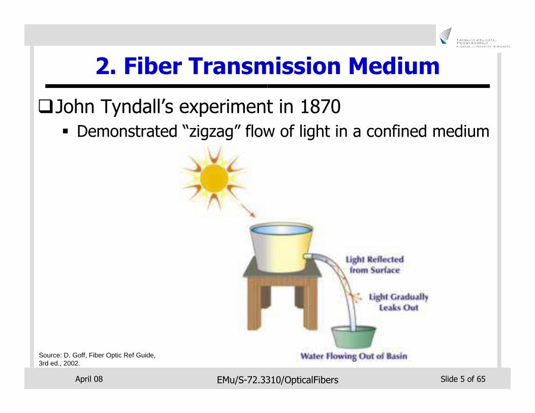
�John Tyndall’s experiment in 1870
� Demonstrated “zigzag” flow of light in a confined medium
Source: D. Goff, Fiber Optic Ref Guide, 3rd ed., 2002.
April 08 EMu/S-72.3310/OpticalFibers Slide 6 of 65
2.1 Operating Wavelength Bands
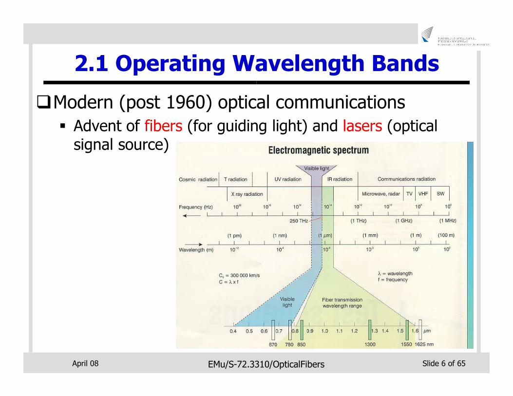
�Modern (post 1960) optical communications
� Advent of fibers (for guiding light) and lasers (optical signal source)
April 08 EMu/S-72.3310/OpticalFibers Slide 7 of 65
2.2 Advantages of Fiber
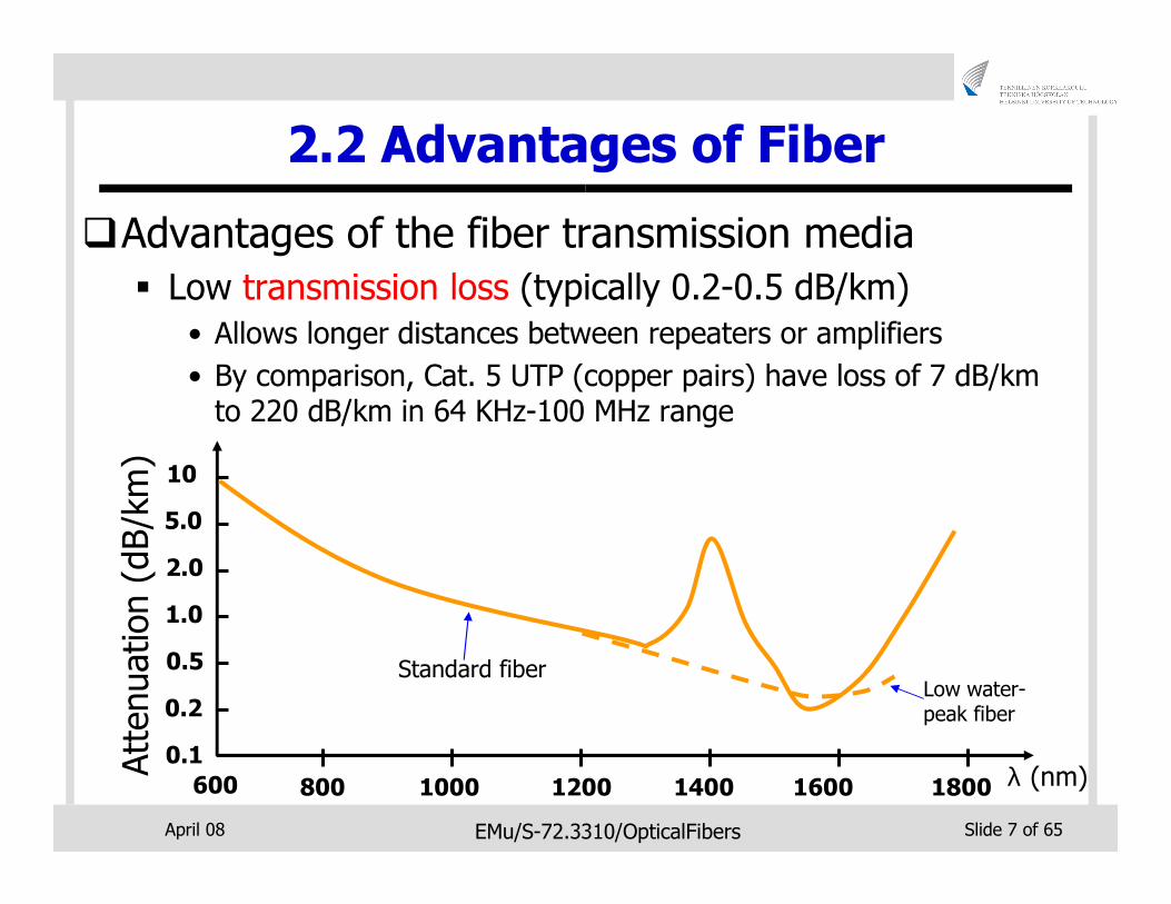
�Advantages of the fiber transmission media
� Low transmission loss (typically 0.2-0.5 dB/km)
• Allows longer distances between repeaters or amplifiers
• By comparison, Cat. 5 UTP (copper pairs) have loss of 7 dB/km to 220 dB/km in 64 KHz-100 MHz range
600
0.1λ (nm)
0.2
0.5
1.0
2.0
5.0
10
Attenuation (dB/km)
800 1000 1200 1400 1600 1800
Standard fiberLow water-peak fiber
April 08 EMu/S-72.3310/OpticalFibers Slide 8 of 65
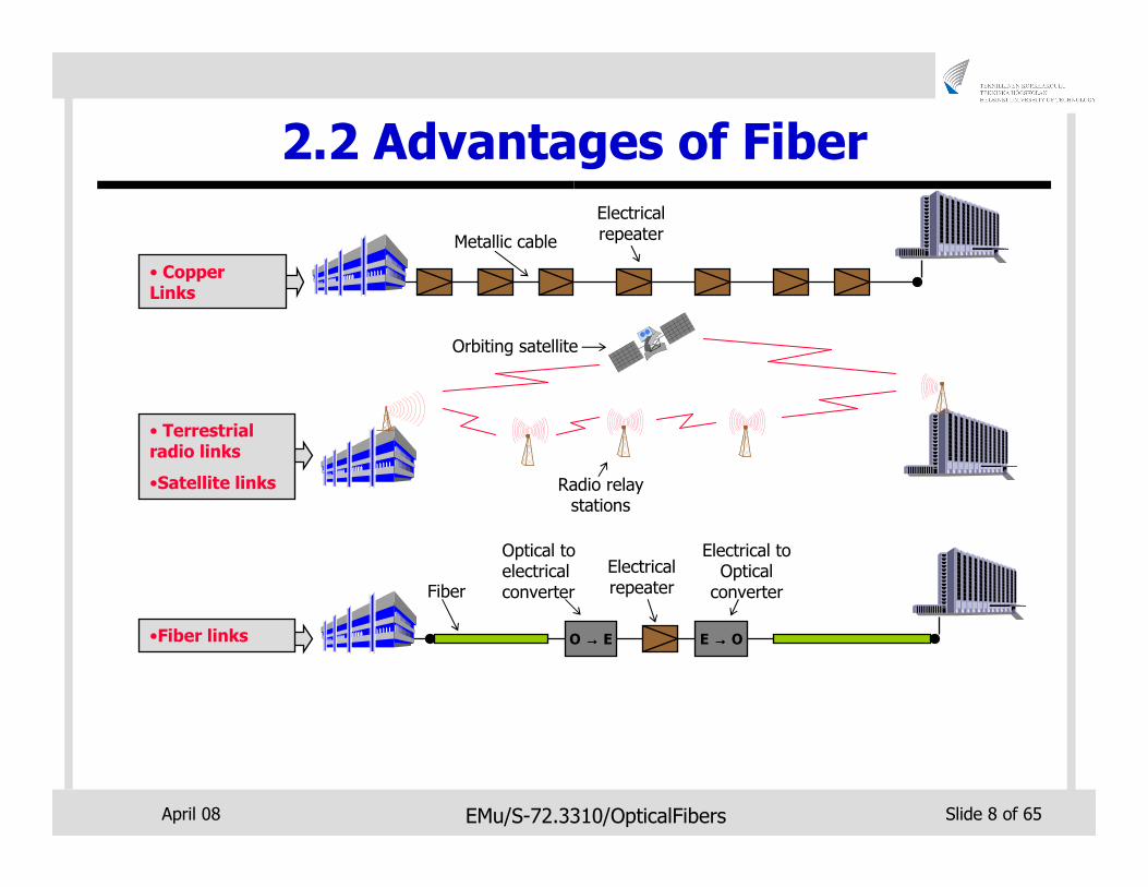
2.2 Advantages of Fiber
Electrical repeaterMetallic cable
• Copper Links
• Terrestrial radio links
•Satellite links Radio relay stations
Orbiting satellite
•Fiber links
Electrical repeater
Electrical to Optical
converter
O →→→→ E E →→→→ O
Optical to electrical converterFiber
April 08 EMu/S-72.3310/OpticalFibers Slide 9 of 65
2.2 Advantages of Fiber
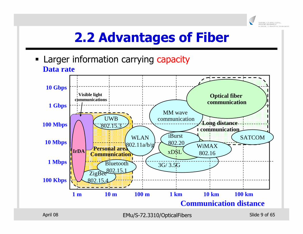
� Larger information carrying capacity
3G/ 3.5G
UWB802.15.3
xDSL
10 Gbps
MM wave communication
1 Gbps
100 Mbps
10 Mbps
1 Mbps
100 Kbps
1 km100 m10 m 10 km1 m
ZigBee802.15.4
WLAN802.11a/b/g
Optical fiber communication
Communication distance
Personal areaCommunicationIrDA
Long distance communication
Data rate
Visible light communications
100 km
iBurst802.20 WiMAX
802.16
Bluetooth802.15.1
SATCOM
April 08 EMu/S-72.3310/OpticalFibers Slide 10 of 65
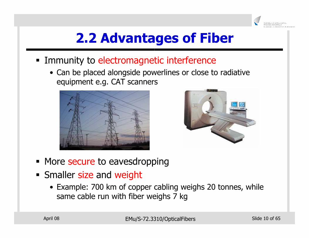
2.2 Advantages of Fiber
� Immunity to electromagnetic interference
• Can be placed alongside powerlines or close to radiative equipment e.g. CAT scanners
� More secure to eavesdropping
� Smaller size and weight
• Example: 700 km of copper cabling weighs 20 tonnes, while same cable run with fiber weighs 7 kg
April 08 EMu/S-72.3310/OpticalFibers Slide 11 of 65
3. Basics of Fiber Propagation
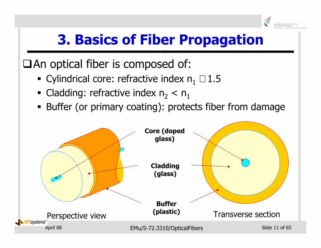
�An optical fiber is composed of:
� Cylindrical core: refractive index n1 ≅ 1.5
� Cladding: refractive index n2 < n1� Buffer (or primary coating): protects fiber from damage
Core (doped glass)
Cladding (glass)
Buffer (plastic)
Perspective view Transverse section
April 08 EMu/S-72.3310/OpticalFibers Slide 12 of 65
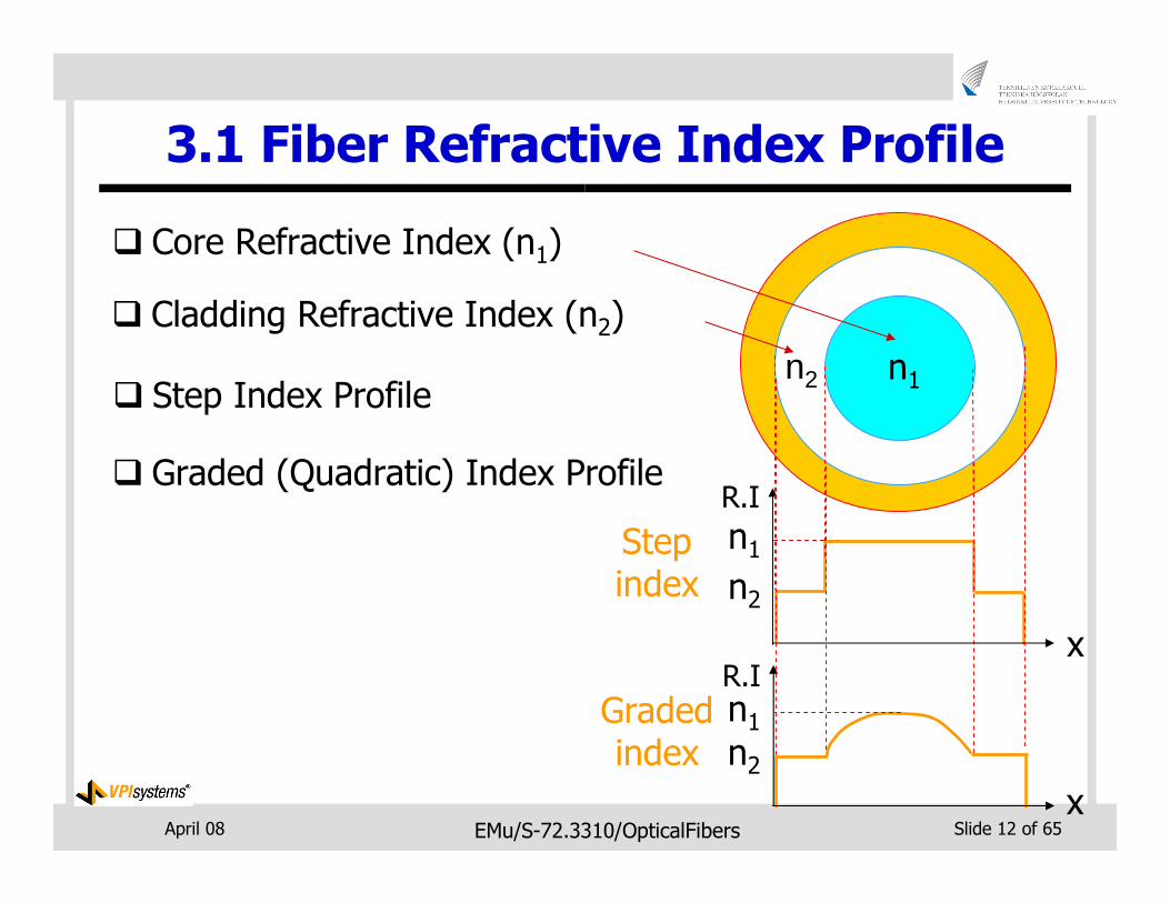
3.1 Fiber Refractive Index Profile
� Core Refractive Index (n1)
� Cladding Refractive Index (n2)
� Step Index Profile
� Graded (Quadratic) Index Profile
n1n2
n2
Step index
Graded index
n2 n1
x
R.I
n1
x
R.I
April 08 EMu/S-72.3310/OpticalFibers Slide 13 of 65
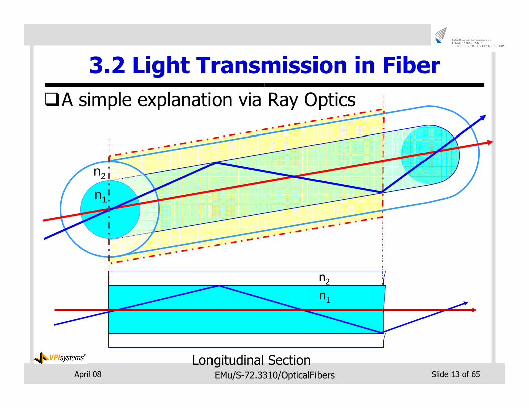
3.2 Light Transmission in Fiber
�A simple explanation via Ray Optics
n1
n2
Longitudinal Section
n2
n1
April 08 EMu/S-72.3310/OpticalFibers Slide 14 of 65
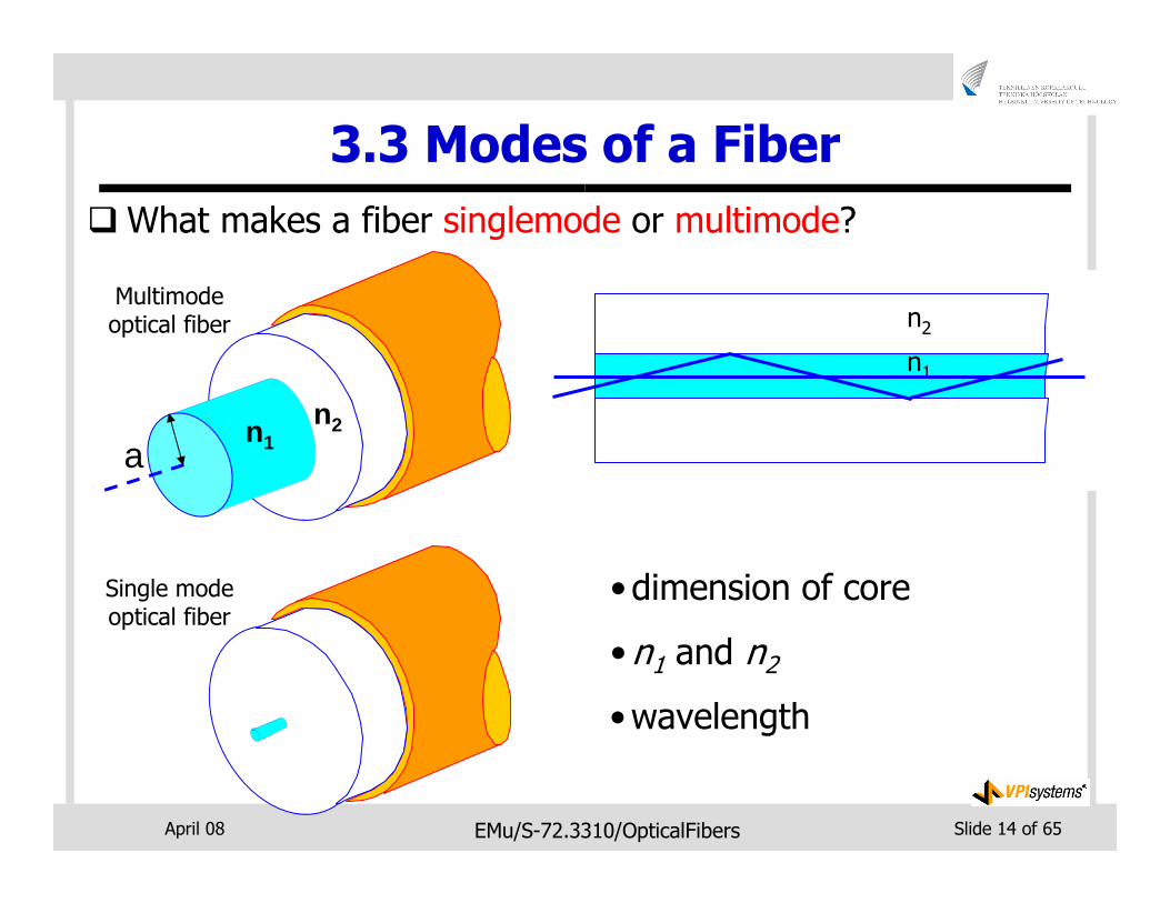
3.3 Modes of a Fiber
�What makes a fiber singlemode or multimode?
Single mode optical fiber
n1
n2
n1
n2n2
n1
•dimension of core
•n1 and n2
•wavelength
Multimode optical fiber
an1
n2
April 08 EMu/S-72.3310/OpticalFibers Slide 15 of 65
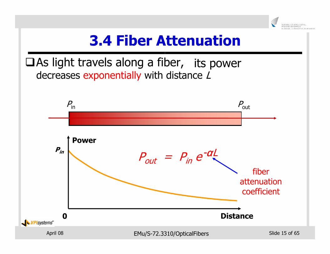
3.4 Fiber Attenuation
�As light travels along a fiber,
Pout = Pin e-ααααL
Pin Pout
Distance
Power
0
Pin
fiber attenuation coefficient
decreases exponentially with distance Lits power
April 08 EMu/S-72.3310/OpticalFibers Slide 16 of 65
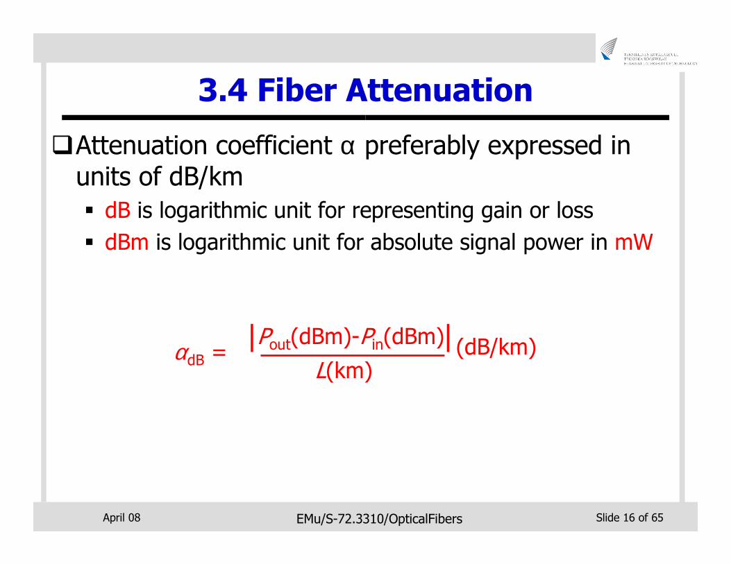
3.4 Fiber Attenuation
�Attenuation coefficient α preferably expressed in units of dB/km
� dB is logarithmic unit for representing gain or loss
� dBm is logarithmic unit for absolute signal power in mW
αdB =L(km)
| |Pout(dBm)-Pin(dBm) (dB/km)
April 08 EMu/S-72.3310/OpticalFibers Slide 17 of 65
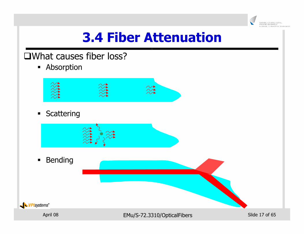
3.4 Fiber Attenuation
�What causes fiber loss?� Absorption
� Scattering
� Bending
April 08 EMu/S-72.3310/OpticalFibers Slide 18 of 65
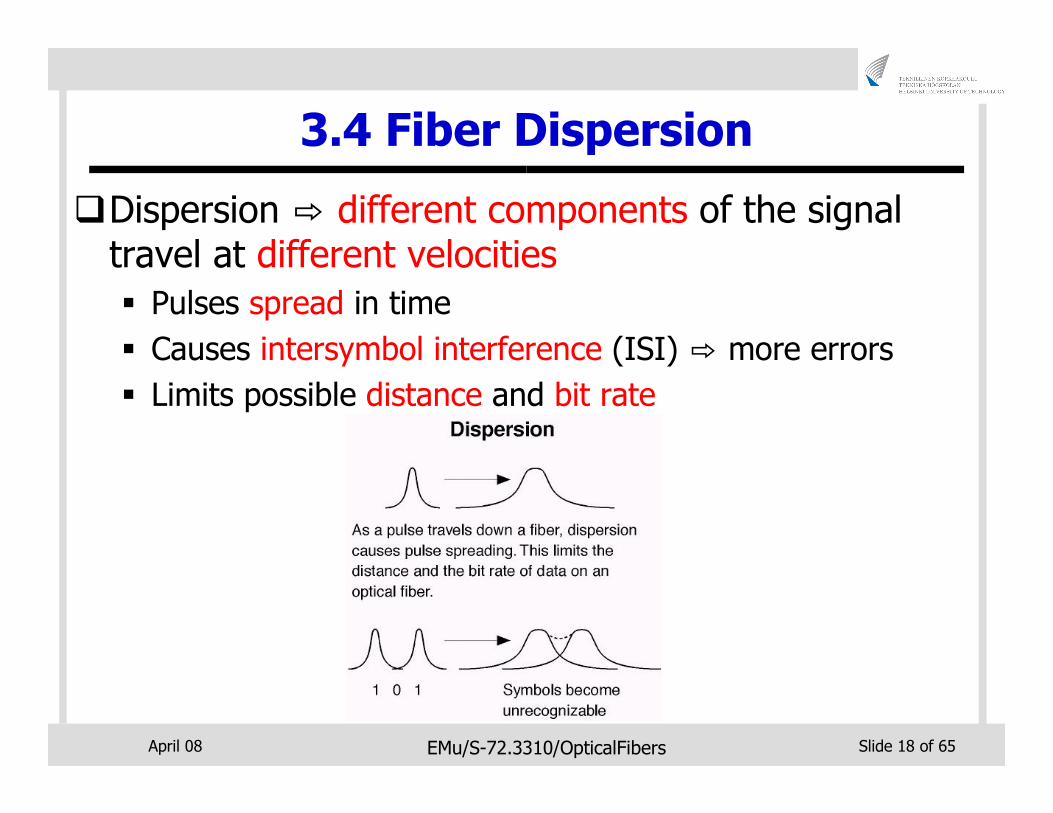
3.4 Fiber Dispersion
�Dispersion ⇨ different components of the signal travel at different velocities
� Pulses spread in time
� Causes intersymbol interference (ISI) ⇨ more errors
� Limits possible distance and bit rate
April 08 EMu/S-72.3310/OpticalFibers Slide 19 of 65
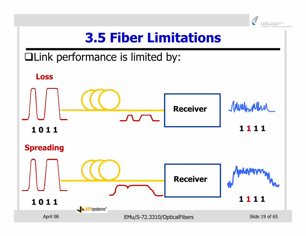
�Link performance is limited by:
Loss
Receiver
Spreading
1 0 1 1 1 1 1 1
Receiver
1 0 1 1 1 1 1 1
3.5 Fiber Limitations
April 08 EMu/S-72.3310/OpticalFibers Slide 20 of 65
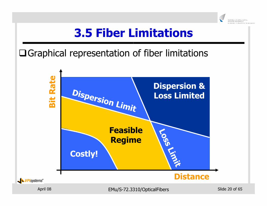
3.5 Fiber Limitations
�Graphical representation of fiber limitations
Distance
Bit Rate
Dispersion & Loss LimitedDispersion Limit
Loss L
imit
Costly!
Feasible Regime
April 08 EMu/S-72.3310/OpticalFibers Slide 21 of 65
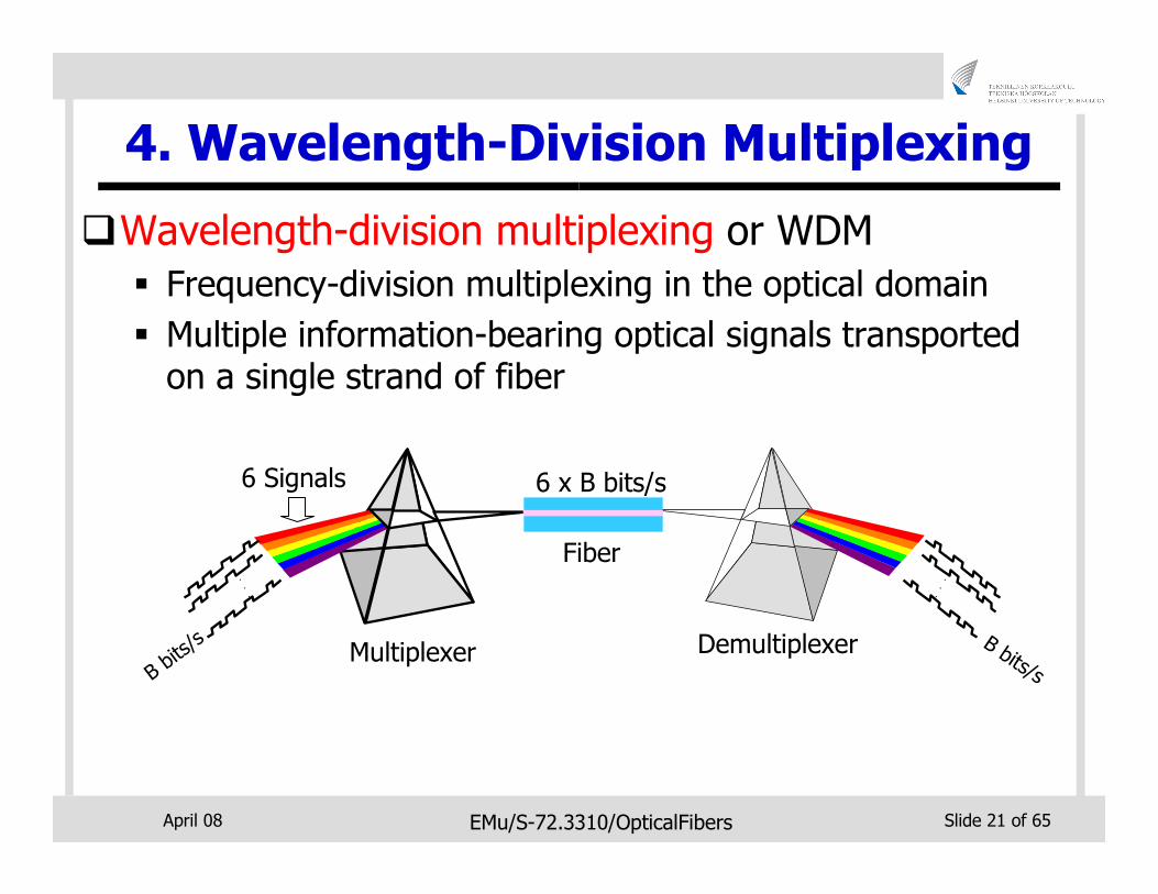
4. Wavelength-Division Multiplexing
�Wavelength-division multiplexing or WDM
� Frequency-division multiplexing in the optical domain
� Multiple information-bearing optical signals transported on a single strand of fiber
6 x B bits/s
..
.
B bits/s
..
.
B bits/sMultiplexer
Fiber
Demultiplexer
6 Signals
April 08 EMu/S-72.3310/OpticalFibers Slide 22 of 65
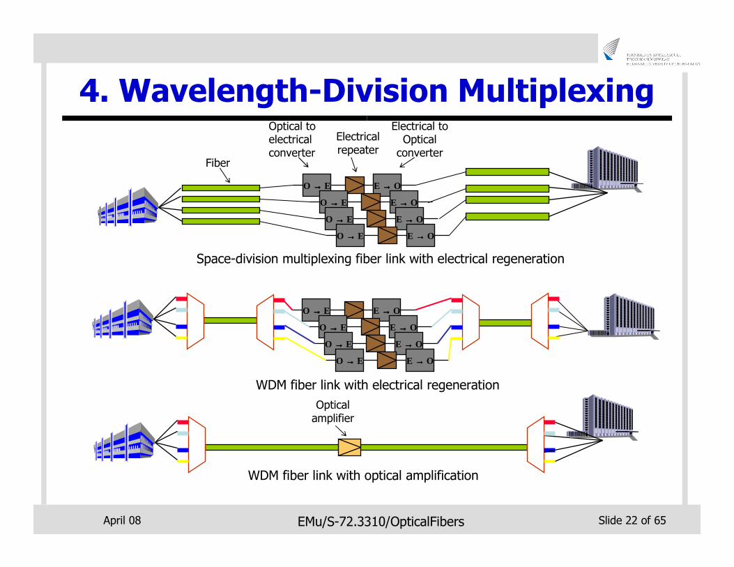
4. Wavelength-Division Multiplexing
Optical amplifier
WDM fiber link with optical amplification
Space-division multiplexing fiber link with electrical regeneration
O →→→→ E E →→→→ O
O →→→→ E E →→→→ O
O →→→→ E E →→→→ O
Electrical repeater
Electrical to Optical
converter
Optical to electrical converter
Fiber
O →→→→ E E →→→→ O
O →→→→ E E →→→→ O
O →→→→ E E →→→→ O
O →→→→ E E →→→→ O
O →→→→ E E →→→→ O
WDM fiber link with electrical regeneration
April 08 EMu/S-72.3310/OpticalFibers Slide 23 of 65
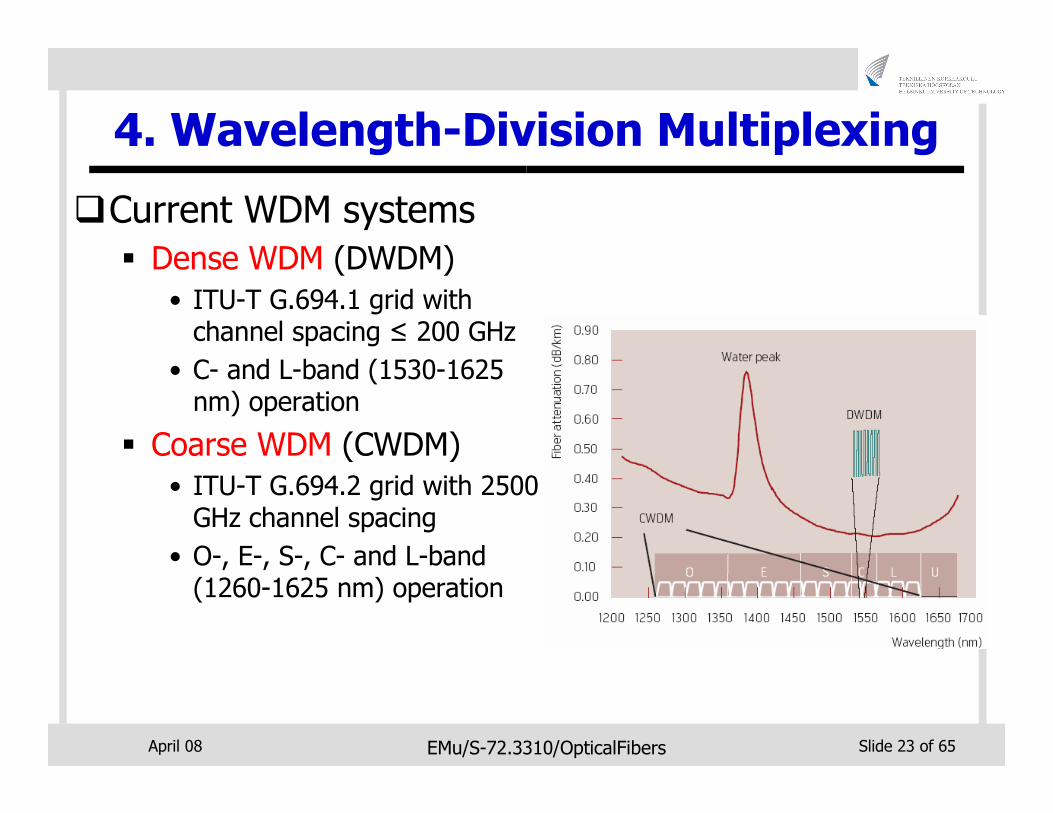
4. Wavelength-Division Multiplexing
�Current WDM systems
� Dense WDM (DWDM)
• ITU-T G.694.1 grid with channel spacing ≤ 200 GHz
• C- and L-band (1530-1625 nm) operation
� Coarse WDM (CWDM)
• ITU-T G.694.2 grid with 2500 GHz channel spacing
• O-, E-, S-, C- and L-band (1260-1625 nm) operation
April 08 EMu/S-72.3310/OpticalFibers Slide 24 of 65
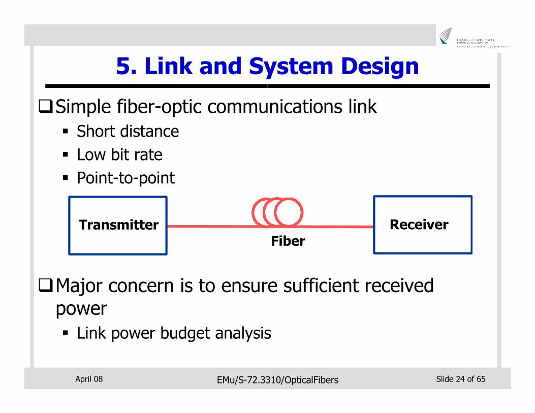
5. Link and System Design
�Simple fiber-optic communications link
� Short distance
� Low bit rate
� Point-to-point
�Major concern is to ensure sufficient received power
� Link power budget analysis
Fiber
ReceiverReceiverTransmitterTransmitter
April 08 EMu/S-72.3310/OpticalFibers Slide 25 of 65
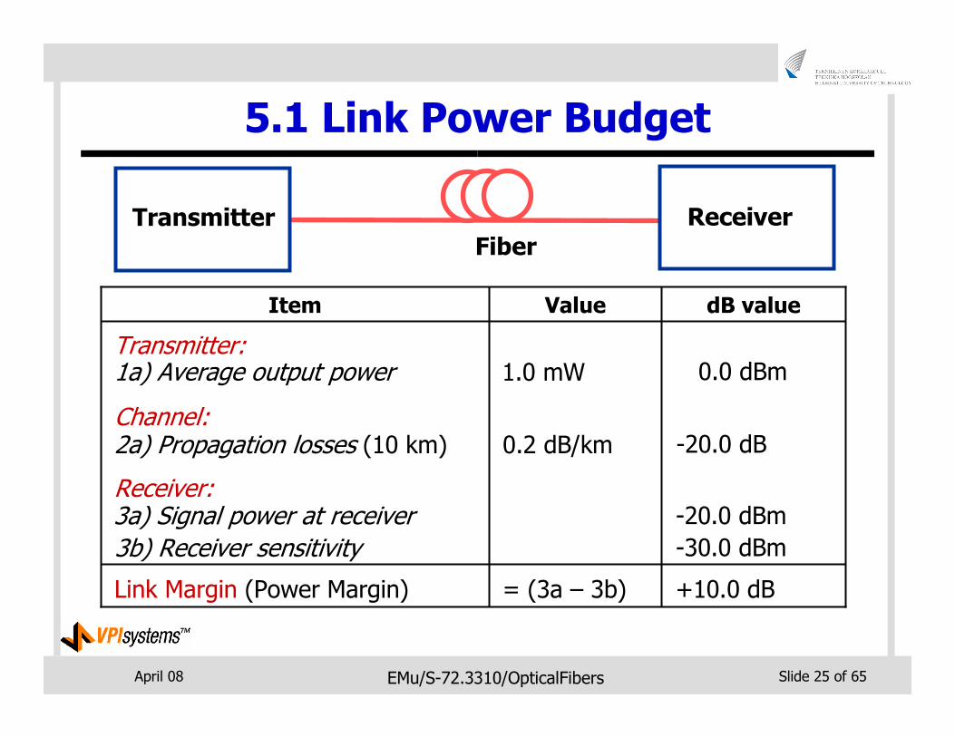
5.1 Link Power Budget
Fiber
ReceiverTransmitter
dB valueValueItem
1a) Average output power
2a) Propagation losses (10 km)
Receiver:3a) Signal power at receiver
3b) Receiver sensitivity
Link Margin (Power Margin)
Transmitter:
Channel:
1.0 mW
0.2 dB/km
= (3a – 3b)
0.0 dBm
-20.0 dB
-20.0 dBm
-30.0 dBm
+10.0 dB
April 08 EMu/S-72.3310/OpticalFibers Slide 26 of 65
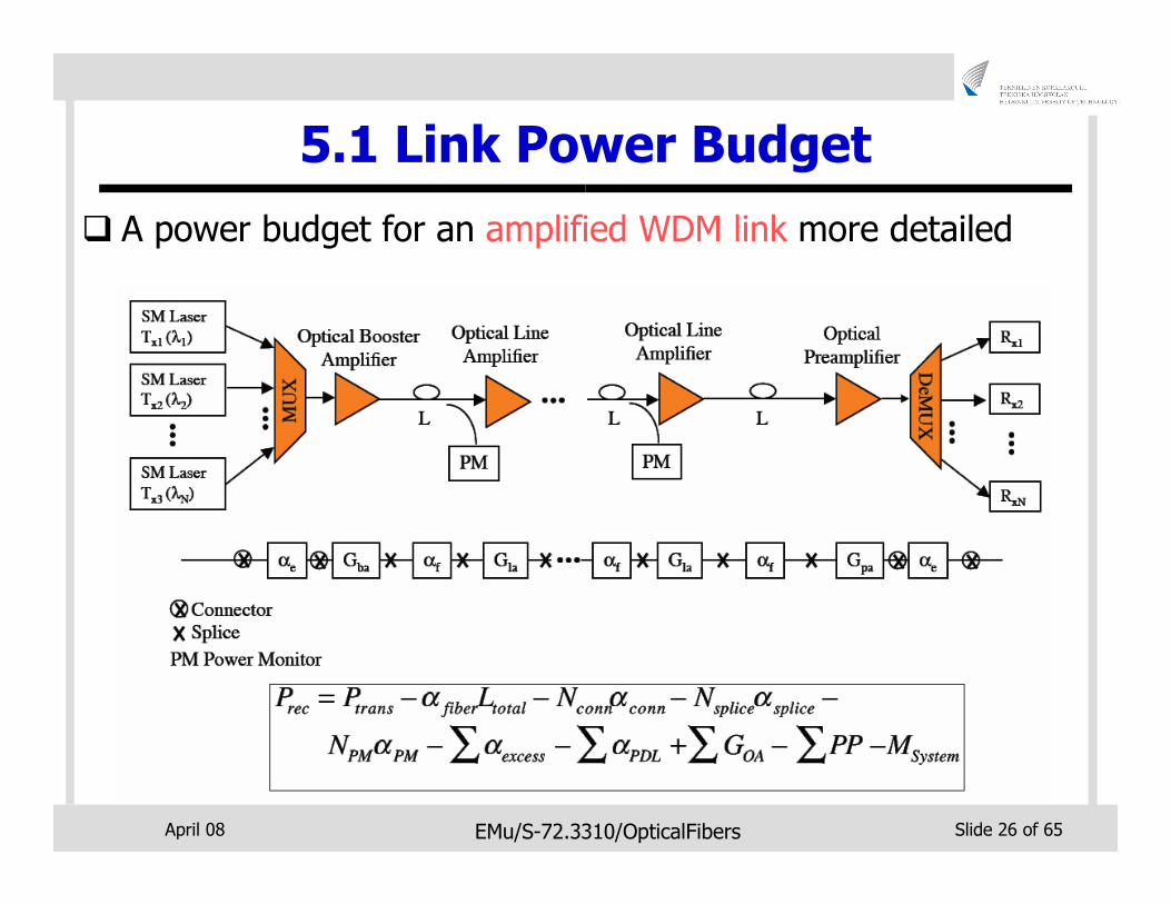
5.1 Link Power Budget
� A power budget for an amplified WDM link more detailed
April 08 EMu/S-72.3310/OpticalFibers Slide 27 of 65
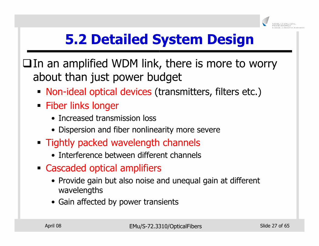
5.2 Detailed System Design
�In an amplified WDM link, there is more to worry about than just power budget
� Non-ideal optical devices (transmitters, filters etc.)
� Fiber links longer
• Increased transmission loss
• Dispersion and fiber nonlinearity more severe
� Tightly packed wavelength channels
• Interference between different channels
� Cascaded optical amplifiers
• Provide gain but also noise and unequal gain at different wavelengths
• Gain affected by power transients
April 08 EMu/S-72.3310/OpticalFibers Slide 28 of 65
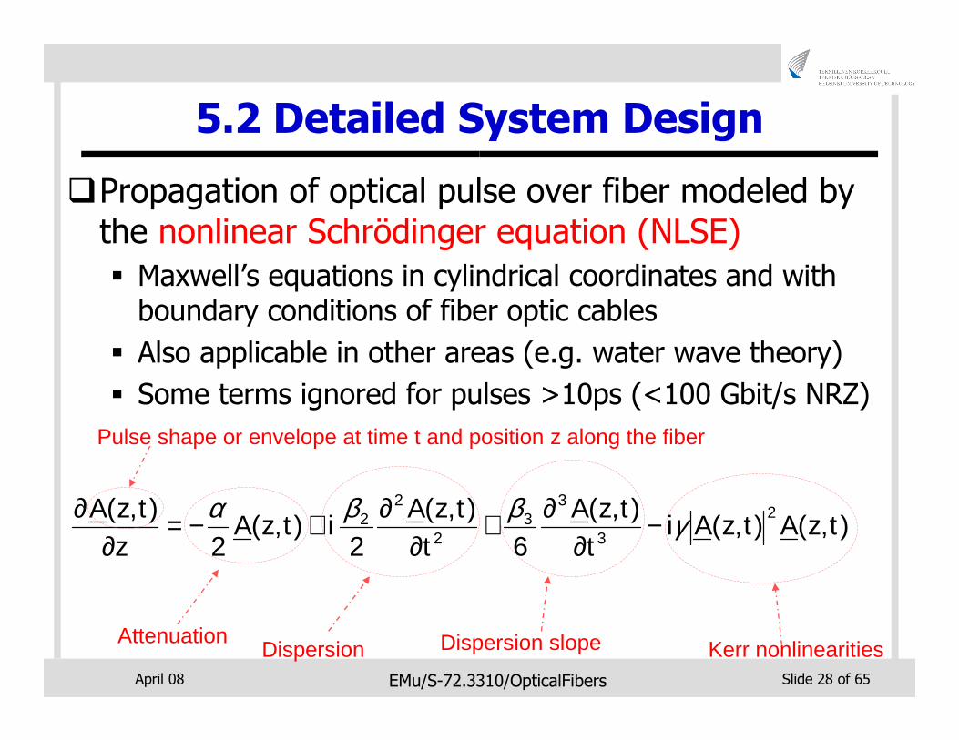
5.2 Detailed System Design
�Propagation of optical pulse over fiber modeled by the nonlinear Schrödinger equation (NLSE)
� Maxwell’s equations in cylindrical coordinates and with boundary conditions of fiber optic cables
� Also applicable in other areas (e.g. water wave theory)
� Some terms ignored for pulses >10ps (<100 Gbit/s NRZ)
),(),(),(
6),(
2),(
2),( 2
3
33
2
22 tzAtzAi
ttzA
ttzA
itzAz
tzA γββα −∂
∂+∂
∂+−=∂
∂
AttenuationDispersion Dispersion slope Kerr nonlinearities
Pulse shape or envelope at time t and position z along the fiber
April 08 EMu/S-72.3310/OpticalFibers Slide 29 of 65
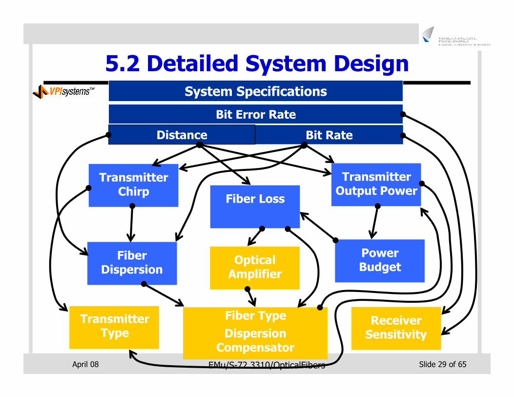
5.2 Detailed System DesignSystem Specifications
Distance Bit Rate
Transmitter Type
Fiber Type Receiver Sensitivity
Fiber Loss
FiberDispersion
Transmitter Chirp
Transmitter Output Power
Power Budget
Optical Amplifier
Bit Error Rate
Dispersion Compensator
April 08 EMu/S-72.3310/OpticalFibers Slide 30 of 65
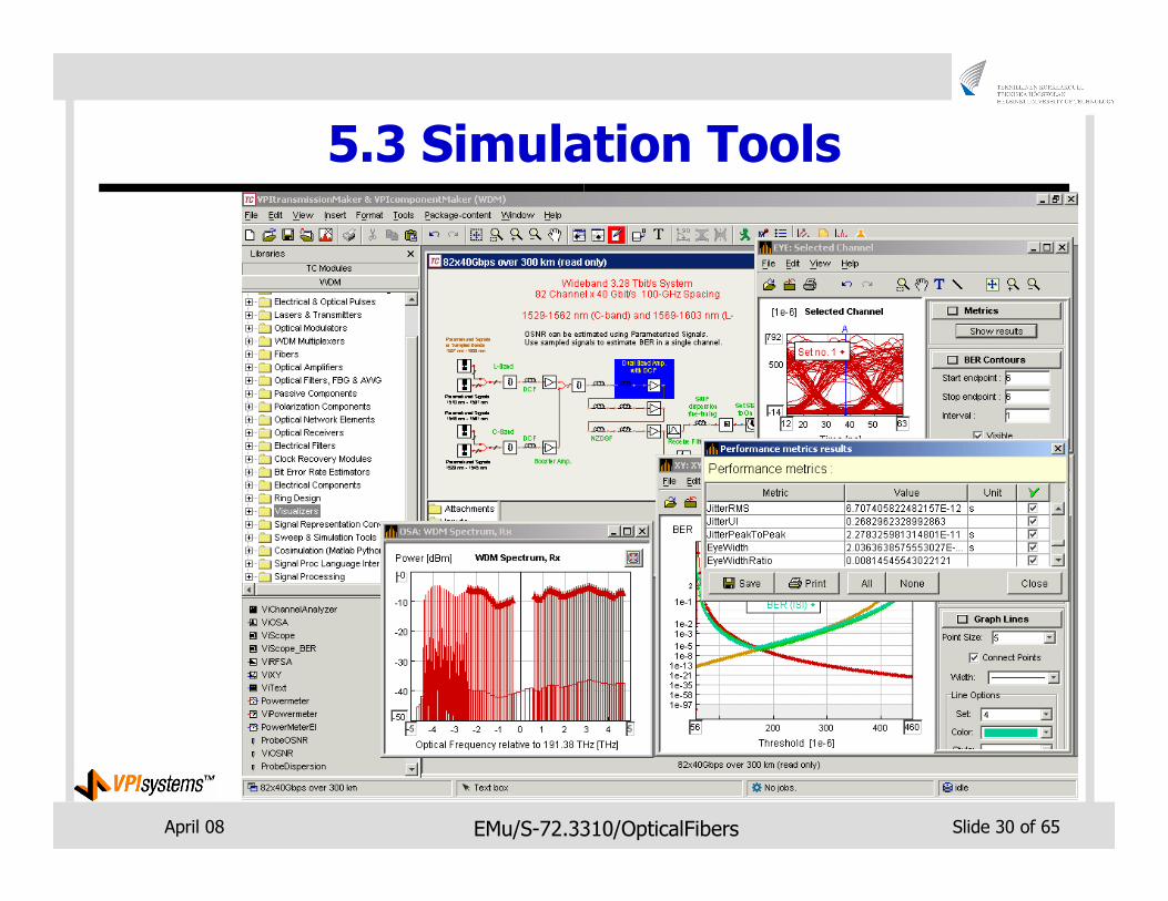
5.3 Simulation Tools
April 08 EMu/S-72.3310/OpticalFibers Slide 31 of 65
Part II: Deployment Considerations
April 08 EMu/S-72.3310/OpticalFibers Slide 32 of 65
1. Introduction
�Optical networks are now widely deployed in different environments
�Special considerations have to be taken when deploying network infrastructure
� Environmental conditions
� Security
� Support facilities
� Cost
� Demand
� Legal considerations
April 08 EMu/S-72.3310/OpticalFibers Slide 33 of 65
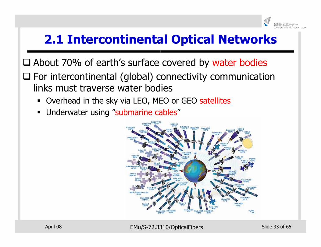
2.1 Intercontinental Optical Networks
� About 70% of earth’s surface covered by water bodies
� For intercontinental (global) connectivity communication links must traverse water bodies
� Overhead in the sky via LEO, MEO or GEO satellites
� Underwater using ”submarine cables”
April 08 EMu/S-72.3310/OpticalFibers Slide 34 of 65
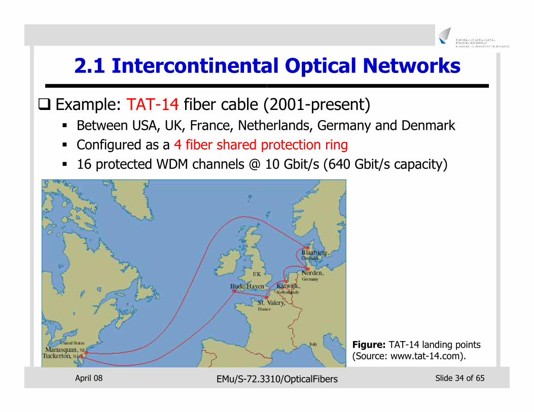
2.1 Intercontinental Optical Networks
� Example: TAT-14 fiber cable (2001-present)
� Between USA, UK, France, Netherlands, Germany and Denmark
� Configured as a 4 fiber shared protection ring
� 16 protected WDM channels @ 10 Gbit/s (640 Gbit/s capacity)
Figure: TAT-14 landing points (Source: www.tat-14.com).
April 08 EMu/S-72.3310/OpticalFibers Slide 35 of 65
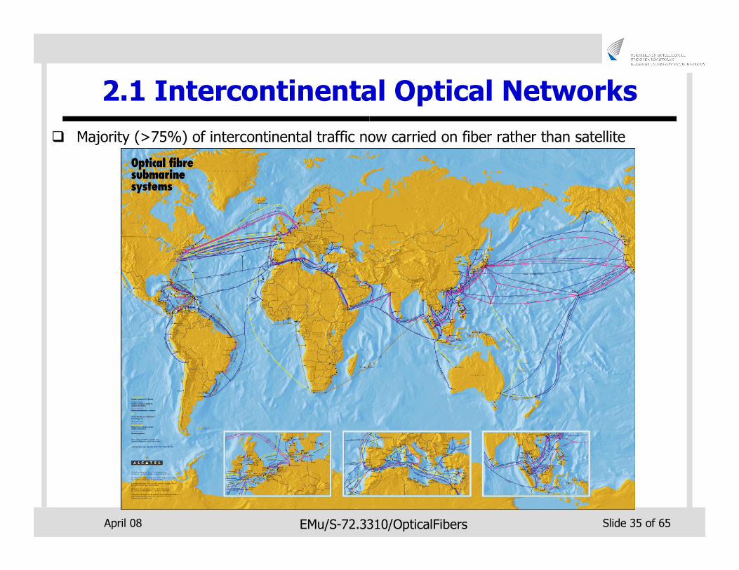
2.1 Intercontinental Optical Networks
� Majority (>75%) of intercontinental traffic now carried on fiber rather than satellite
April 08 EMu/S-72.3310/OpticalFibers Slide 36 of 65
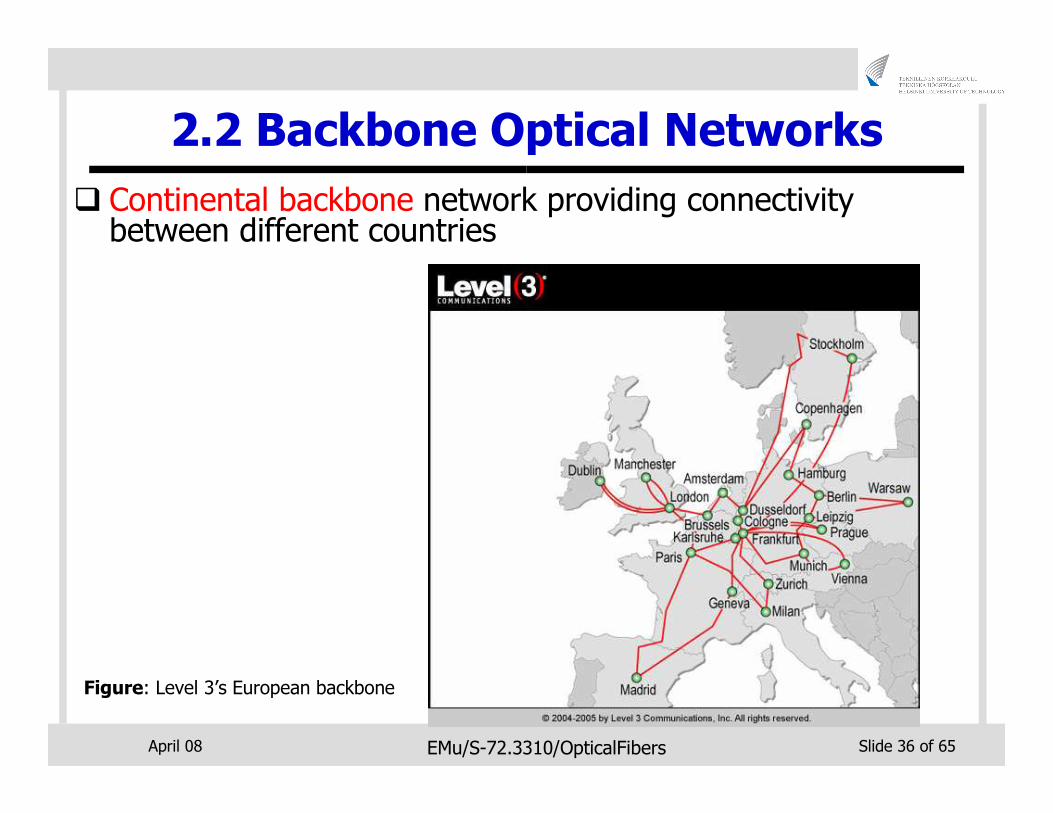
2.2 Backbone Optical Networks
� Continental backbone network providing connectivity between different countries
Figure: Level 3’s European backbone
April 08 EMu/S-72.3310/OpticalFibers Slide 37 of 65
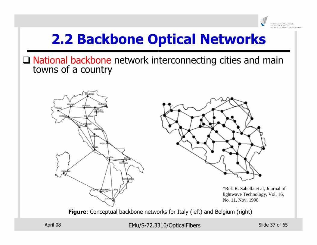
2.2 Backbone Optical Networks
� National backbone network interconnecting cities and main towns of a country
Figure: Conceptual backbone networks for Italy (left) and Belgium (right)
*Ref: R. Sabella et al, Journal of lightwave Technology, Vol. 16, No. 11, Nov. 1998
April 08 EMu/S-72.3310/OpticalFibers Slide 38 of 65
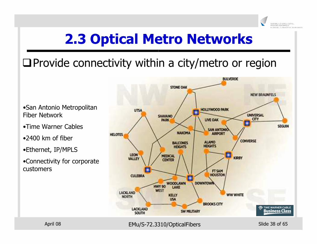
2.3 Optical Metro Networks
�Provide connectivity within a city/metro or region
•San Antonio Metropolitan Fiber Network
•Time Warner Cables
•2400 km of fiber
•Ethernet, IP/MPLS
•Connectivity for corporate customers
April 08 EMu/S-72.3310/OpticalFibers Slide 39 of 65
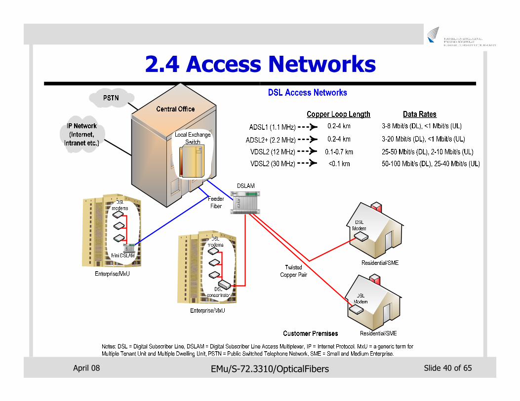
2.4 Access Networks
�Access network are “last leg” of telecommunications network
� Between service provider distribution facility and user’s home or business
� Other names:
• last mile
• local loop
• first mile
• etc.
�Fiber is increasingly deployed now in access networks
April 08 EMu/S-72.3310/OpticalFibers Slide 40 of 65
2.4 Access Networks
April 08 EMu/S-72.3310/OpticalFibers Slide 41 of 65
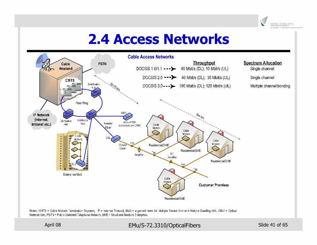
2.4 Access Networks
few km
50-70 km
April 08 EMu/S-72.3310/OpticalFibers Slide 42 of 65
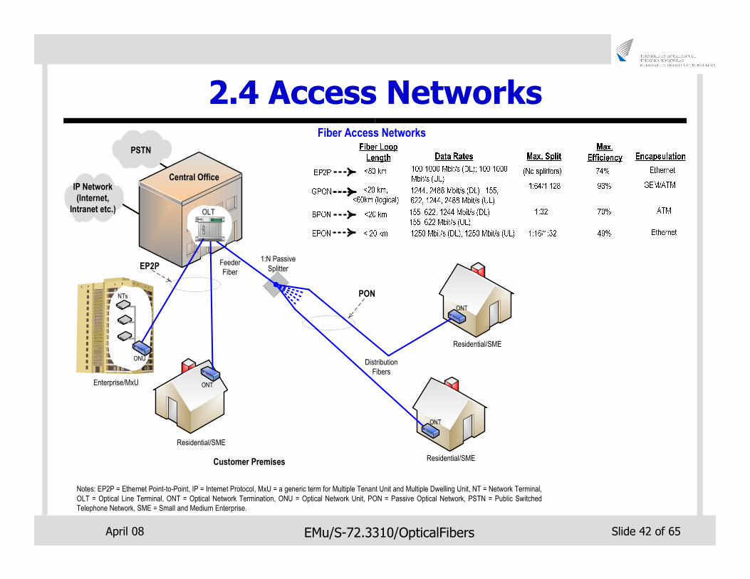
2.4 Access Networks
IP Network
(Internet,
Intranet etc.)
PSTN
1:N Passive
SplitterFeeder
Fiber
Central Office
ONT
ONT
EP2P
PON
OLT
Fiber Access Networks
Distribution
Fibers
Notes: EP2P = Ethernet Point-to-Point, IP = Internet Protocol, MxU = a generic term for Multiple Tenant Unit and Multiple Dwelling Unit, NT = Network Terminal,
OLT = Optical Line Terminal, ONT = Optical Network Termination, ONU = Optical Network Unit, PON = Passive Optical Network, PSTN = Public Switched
Telephone Network, SME = Small and Medium Enterprise.
Residential/SME
Residential/SME
NTs
Enterprise/MxU
ONU
ONT
Residential/SME
Customer Premises
April 08 EMu/S-72.3310/OpticalFibers Slide 43 of 65
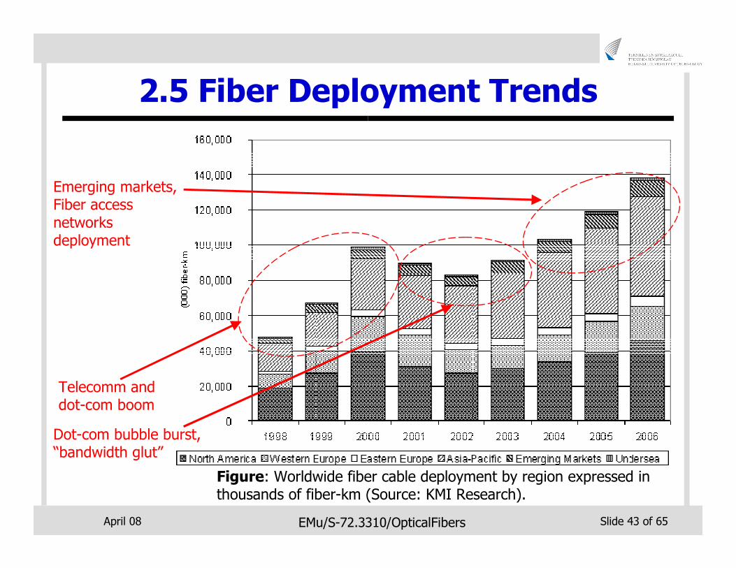
2.5 Fiber Deployment Trends
Figure: Worldwide fiber cable deployment by region expressed in thousands of fiber-km (Source: KMI Research).
Telecomm and dot-com boom
Dot-com bubble burst, “bandwidth glut”
Emerging markets, Fiber access networks deployment
April 08 EMu/S-72.3310/OpticalFibers Slide 44 of 65
3. Deployment Methods
�Various methods exist for deployment of fibercables
�Selected cable deployment method depends on various factors
� Geographical topography of an area
� Availability of rights-of-way
� Time constraints
� Operator’s business strategy
April 08 EMu/S-72.3310/OpticalFibers Slide 45 of 65
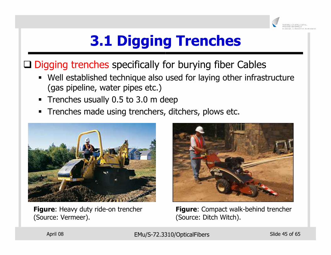
3.1 Digging Trenches
� Digging trenches specifically for burying fiber Cables
� Well established technique also used for laying other infrastructure (gas pipeline, water pipes etc.)
� Trenches usually 0.5 to 3.0 m deep
� Trenches made using trenchers, ditchers, plows etc.
Figure: Heavy duty ride-on trencher (Source: Vermeer).
Figure: Compact walk-behind trencher (Source: Ditch Witch).
April 08 EMu/S-72.3310/OpticalFibers Slide 46 of 65
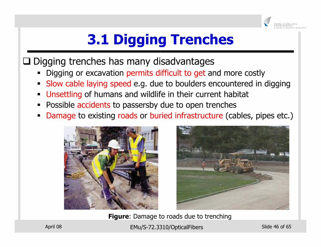
3.1 Digging Trenches
� Digging trenches has many disadvantages� Digging or excavation permits difficult to get and more costly
� Slow cable laying speed e.g. due to boulders encountered in digging
� Unsettling of humans and wildlife in their current habitat
� Possible accidents to passersby due to open trenches
� Damage to existing roads or buried infrastructure (cables, pipes etc.)
Figure: Damage to roads due to trenching
April 08 EMu/S-72.3310/OpticalFibers Slide 47 of 65
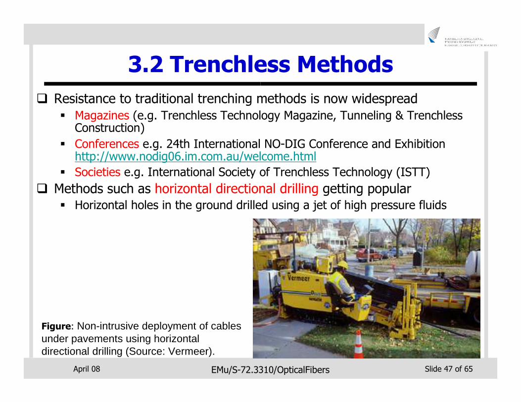
3.2 Trenchless Methods
� Resistance to traditional trenching methods is now widespread
� Magazines (e.g. Trenchless Technology Magazine, Tunneling & Trenchless Construction)
� Conferences e.g. 24th International NO-DIG Conference and Exhibition http://www.nodig06.im.com.au/welcome.html
� Societies e.g. International Society of Trenchless Technology (ISTT)
� Methods such as horizontal directional drilling getting popular� Horizontal holes in the ground drilled using a jet of high pressure fluids
Figure: Non-intrusive deployment of cables under pavements using horizontal directional drilling (Source: Vermeer).
April 08 EMu/S-72.3310/OpticalFibers Slide 48 of 65
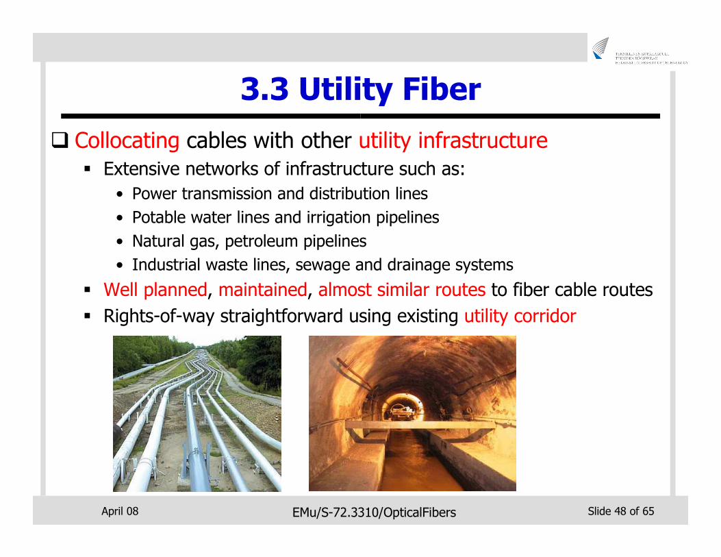
3.3 Utility Fiber
� Collocating cables with other utility infrastructure
� Extensive networks of infrastructure such as:
• Power transmission and distribution lines
• Potable water lines and irrigation pipelines
• Natural gas, petroleum pipelines
• Industrial waste lines, sewage and drainage systems
� Well planned, maintained, almost similar routes to fiber cable routes
� Rights-of-way straightforward using existing utility corridor
April 08 EMu/S-72.3310/OpticalFibers Slide 49 of 65
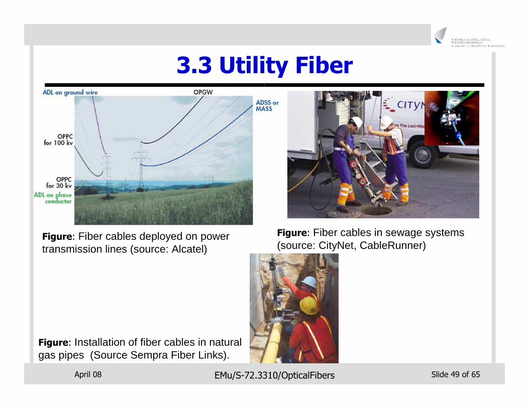
3.3 Utility Fiber
Figure: Fiber cables deployed on power transmission lines (source: Alcatel)
Figure: Fiber cables in sewage systems (source: CityNet, CableRunner)
Figure: Installation of fiber cables in natural gas pipes (Source Sempra Fiber Links).
April 08 EMu/S-72.3310/OpticalFibers Slide 50 of 65
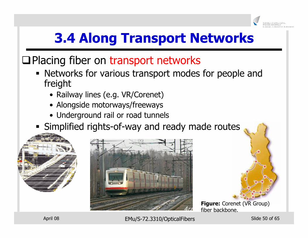
3.4 Along Transport Networks
�Placing fiber on transport networks� Networks for various transport modes for people and freight• Railway lines (e.g. VR/Corenet)
• Alongside motorways/freeways
• Underground rail or road tunnels
� Simplified rights-of-way and ready made routes
Figure: Corenet (VR Group) fiber backbone.
April 08 EMu/S-72.3310/OpticalFibers Slide 51 of 65
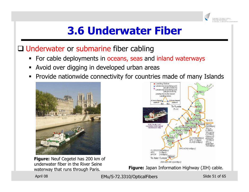
3.6 Underwater Fiber
� Underwater or submarine fiber cabling
� For cable deployments in oceans, seas and inland waterways
� Avoid over digging in developed urban areas
� Provide nationwide connectivity for countries made of many Islands
Figure: Japan Information Highway (JIH) cable.
Figure: Neuf Cegetel has 200 km of underwater fiber in the River Seine waterway that runs through Paris.
April 08 EMu/S-72.3310/OpticalFibers Slide 52 of 65
4. Miscellaneous Networks
�Optical networking technologies now used for various non-conventional applications
�Introduce high-capacity and low signal lossadvantages to new application environments
�Need for some device modifications from traditional optical networks
� Different operating environment
� Unfamiliar traffic types
April 08 EMu/S-72.3310/OpticalFibers Slide 53 of 65
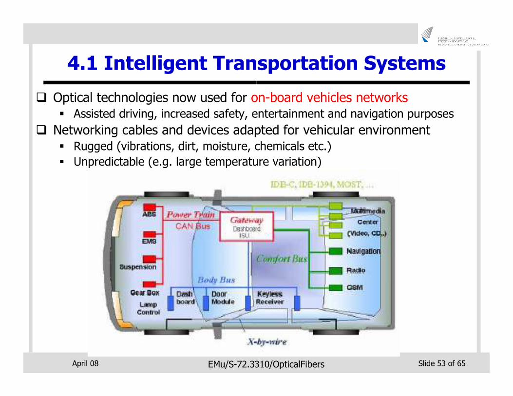
4.1 Intelligent Transportation Systems
� Optical technologies now used for on-board vehicles networks� Assisted driving, increased safety, entertainment and navigation purposes
� Networking cables and devices adapted for vehicular environment � Rugged (vibrations, dirt, moisture, chemicals etc.)
� Unpredictable (e.g. large temperature variation)
April 08 EMu/S-72.3310/OpticalFibers Slide 54 of 65
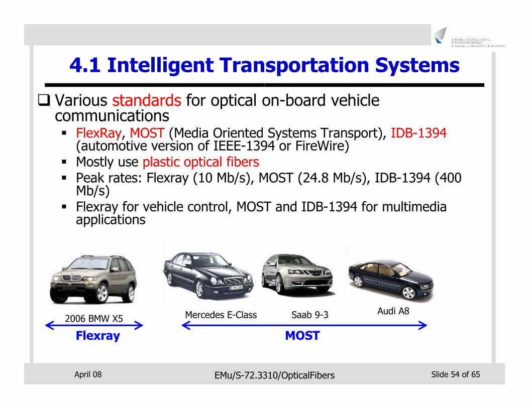
4.1 Intelligent Transportation Systems
� Various standards for optical on-board vehicle communications� FlexRay, MOST (Media Oriented Systems Transport), IDB-1394
(automotive version of IEEE-1394 or FireWire)� Mostly use plastic optical fibers� Peak rates: Flexray (10 Mb/s), MOST (24.8 Mb/s), IDB-1394 (400
Mb/s)� Flexray for vehicle control, MOST and IDB-1394 for multimedia
applications
2006 BMW X5 Mercedes E-Class Saab 9-3 Audi A8
Flexray MOST
April 08 EMu/S-72.3310/OpticalFibers Slide 55 of 65
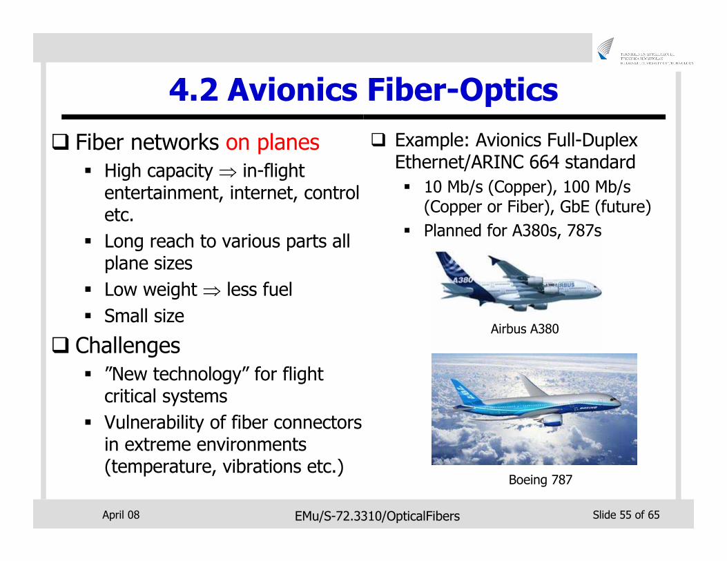
4.2 Avionics Fiber-Optics
� Fiber networks on planes
� High capacity ⇒ in-flight entertainment, internet, control etc.
� Long reach to various parts all plane sizes
� Low weight ⇒ less fuel
� Small size
� Challenges
� ”New technology” for flight critical systems
� Vulnerability of fiber connectors in extreme environments (temperature, vibrations etc.)
� Example: Avionics Full-Duplex Ethernet/ARINC 664 standard
� 10 Mb/s (Copper), 100 Mb/s (Copper or Fiber), GbE (future)
� Planned for A380s, 787s
Airbus A380
Boeing 787
April 08 EMu/S-72.3310/OpticalFibers Slide 56 of 65
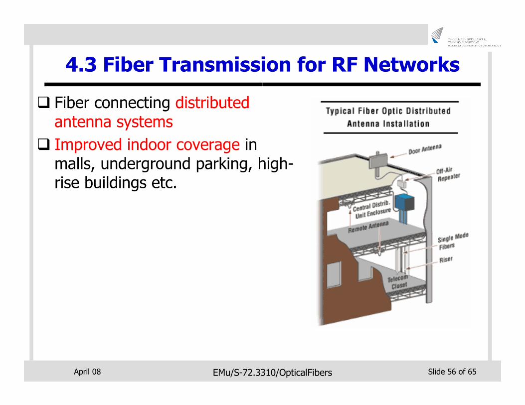
4.3 Fiber Transmission for RF Networks
� Fiber connecting distributed antenna systems
� Improved indoor coverage in malls, underground parking, high-rise buildings etc.
April 08 EMu/S-72.3310/OpticalFibers Slide 57 of 65
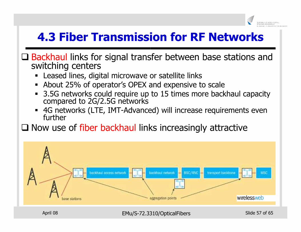
4.3 Fiber Transmission for RF Networks
� Backhaul links for signal transfer between base stations and switching centers� Leased lines, digital microwave or satellite links � About 25% of operator’s OPEX and expensive to scale� 3.5G networks could require up to 15 times more backhaul capacity
compared to 2G/2.5G networks� 4G networks (LTE, IMT-Advanced) will increase requirements even
further
� Now use of fiber backhaul links increasingly attractive
April 08 EMu/S-72.3310/OpticalFibers Slide 58 of 65
4.4 Optical Wireless
�Transmission of infrared beams (optical signals) in free space (fiberless)� Also known as free space optics (FSO)
� Utilize conventional optical 1300/1550 nm transmitters and receivers with some slight modifications
April 08 EMu/S-72.3310/OpticalFibers Slide 59 of 65
4.4 Optical Wireless
�Advantages of FSO over fiber communications
� Tetherless flexibility
� Cost-effectiveness
�Advantages of FSO over RF wireless communications
� Availability of large unregulated unlicensed bandwidth
� Data rates up to a several Gbit/s possible
� Links usually not affected by multipath fading
April 08 EMu/S-72.3310/OpticalFibers Slide 60 of 65
4.4 Optical Wireless
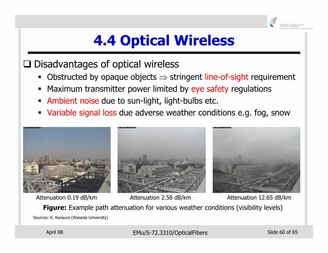
� Disadvantages of optical wireless
� Obstructed by opaque objects ⇒ stringent line-of-sight requirement
� Maximum transmitter power limited by eye safety regulations
� Ambient noise due to sun-light, light-bulbs etc.
� Variable signal loss due adverse weather conditions e.g. fog, snow
Attenuation 0.19 dB/km
Sources: K. Kazaura (Waseda University)
Attenuation 2.58 dB/km Attenuation 12.65 dB/km
Figure: Example path attenuation for various weather conditions (visibility levels)
April 08 EMu/S-72.3310/OpticalFibers Slide 61 of 65
4.4 Optical Wireless
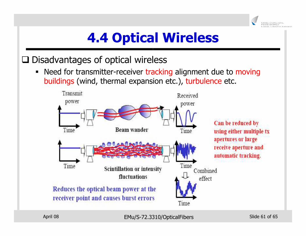
� Disadvantages of optical wireless
� Need for transmitter-receiver tracking alignment due to moving buildings (wind, thermal expansion etc.), turbulence etc.
April 08 EMu/S-72.3310/OpticalFibers Slide 62 of 65
4.4 Optical Wireless
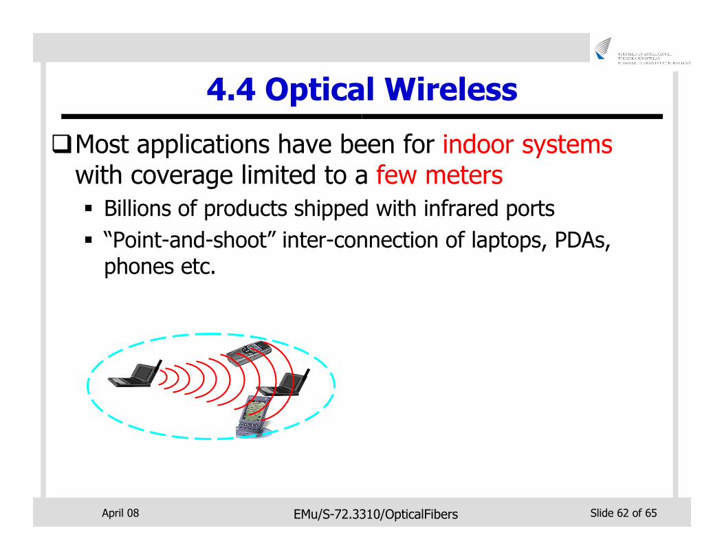
�Most applications have been for indoor systemswith coverage limited to a few meters
� Billions of products shipped with infrared ports
� “Point-and-shoot” inter-connection of laptops, PDAs, phones etc.
April 08 EMu/S-72.3310/OpticalFibers Slide 63 of 65
4.4 Optical Wireless
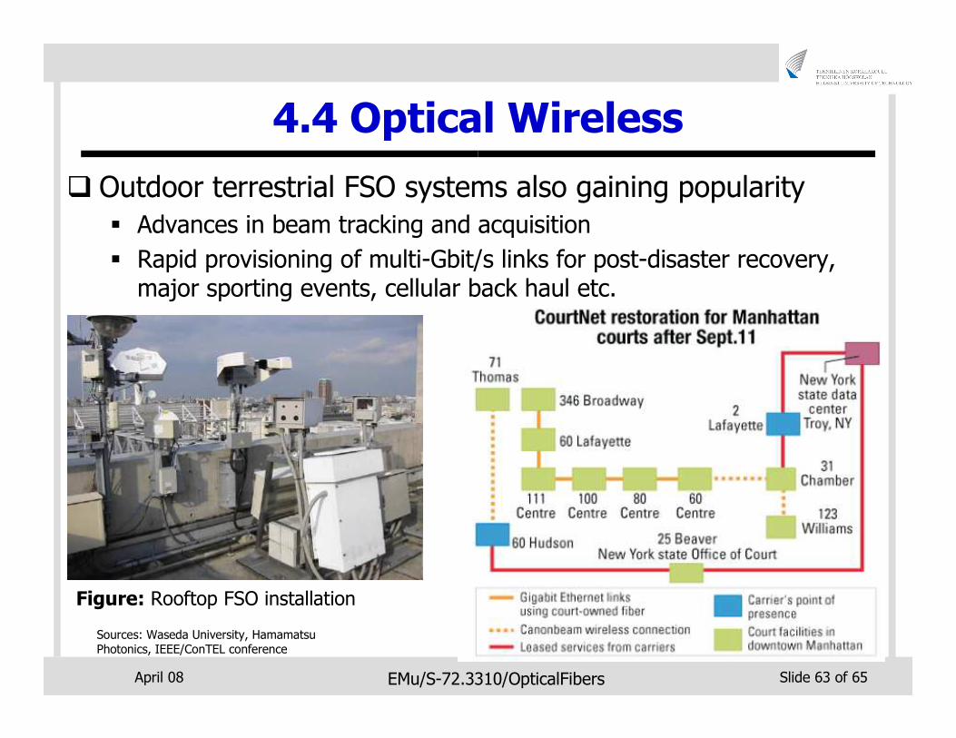
� Outdoor terrestrial FSO systems also gaining popularity
� Advances in beam tracking and acquisition
� Rapid provisioning of multi-Gbit/s links for post-disaster recovery, major sporting events, cellular back haul etc.
Sources: Waseda University, Hamamatsu Photonics, IEEE/ConTEL conference
Figure: Rooftop FSO installation
April 08 EMu/S-72.3310/OpticalFibers Slide 64 of 65
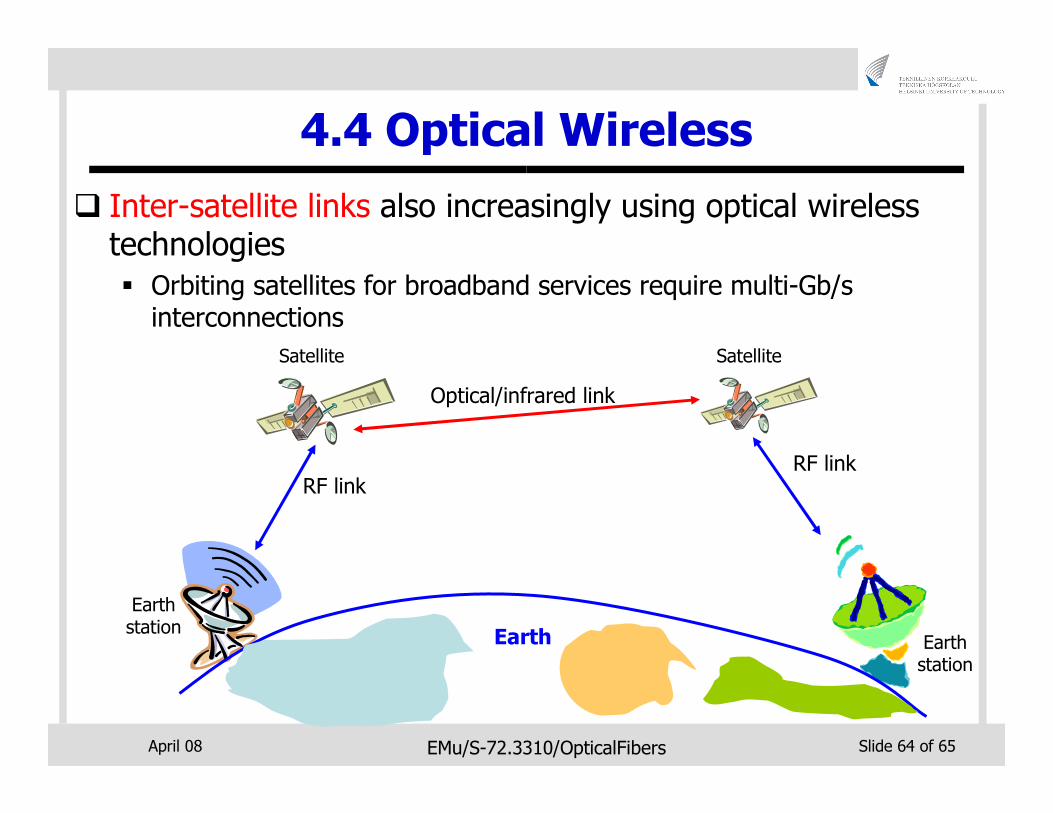
4.4 Optical Wireless
� Inter-satellite links also increasingly using optical wireless technologies
� Orbiting satellites for broadband services require multi-Gb/sinterconnections
Earth
RF linkRF link
Optical/infrared link
Satellite Satellite
Earthstation
Earthstation
April 08 EMu/S-72.3310/OpticalFibers Slide 65 of 65
6. Conclusions
�Optical networks are now an integral part of manycurrent systems
�Fiber likely to get even closer to the user e.g. fiber-to-the-desk

April 08 EMu/S-72.3310/OpticalFibers Slide 66 of 65
Thank You!


![Optical Communications [OC]](https://img.pdfslide.us/doc/110x75/577d1fe11a28ab4e1e918737/optical-communications-oc.jpg)