Embed Size (px)
Citation preview

The TESLA Cavity: Design Considerations and RF Properties
Deutsches Elektronen-Synchrotron DESY NotkestraBe 85, 22603 Hamburg, Germany
1. Abstract
This paper summarizes the effort of the TESLA collaboration in designing the electrical properties of the superconducting TESLA cavity. The work was started in 1990 at the first TESLA workshop at Cornell [l]. At the time of writing this paper several Cu and two Nb cavities have been fabricated and measured. In the first part design considerations concerning choice of frequency, number of cells and optimization of shape are discussed. The second part describes results of calculations and measurements. A detailed discussion of the mechanical layout of the TESLA cavity is given in PI .
2. Introduction
Superconducting cavities are in operation at storage rings (HERA, LEP, Tristan) and at linacs (CEBAF, Darmstadt, HEPL). In a storage ring the relative high beam current results in a cavity design with higher order mode (HOM) and fundamental mode couplers of strong coupling values. The design specification for both input and HOM couplers is relaxed in linac application. The superconducting cavities are operated under continuous (cw) conditions in all existing accelerators. Operating gradients around 5 MVIm are specified although recent measurements at CEBAF show higher gradients for mass produced cavities [3]. For TESLA much higher gradients (25 MVIm) are needed to keep the length of a 1 TeV linear collider short enough. The quadratic increase of the surface loss with accelerating gradient results in a need of pulsed operation to bring the cryogenic effort down. Therefore it was necessary to reconsider the design criteria for a superconducting cavity for TESLA.
Proceedings of the Sixth Workshop on RF Superconductivity, CEBAF, Newport News, Virginia, USA
SRF93G01

3. Design Considerations
Parameters like fundamental frequency, number of cells, shape of the cavity and higher order mode damping have to be fixed in designing a superconducting cavity. Some parameters will influence other design values and vice versa. For example a strong coupling HOM damper allows to go to a high number of cells per coupler. The coupling strength, on the other hand, can only be determined after elaborate measurement on a model with given number of cells. The conclusion of the measurement might be to increase or to reduce the number of cells. It is not clear whether there is a straight forward optimization process to find the overall design maximum.
3.1 Choice of freauencv
There are distinct arguments for the choice of a high or low fundamental mode frequency (see Table 1).
Table 1: Choice of frequency
high:
low:
Arguments in favor of high frequency are: The shunt impedance per length increases linearly with frequency. This means that the cryogenic loss decreases if one assumes a constant cavity quality factor Q. If one takes into account the temperature and frequency dependent surface resistance, then an optimum temperature has to be determined for each frequency. The analysis in [4] concludes, that at higher frequencies the cryogenic effort is reduced and the optimum temperature is lowered.
high r/Q (low cryogenic load at fundamental) small surface area low stored energy low dark current small wakes (K_L,K_LI) low HOM power long cavity module (for fixed # of cells) low R B C ~ (thermally stable at high gradient)
broad minimum of total cryogenic load for 1 ... 3 GHz low frequency
1.3 GHz, klystrons available .
Proceedings of the Sixth Workshop on RF Superconductivity, CEBAF, Newport News, Virginia, USA
SRF93G01

The surface area of the cavity decreases with increasing frequency. An analysis of the maximum surface fields measured shows, that higher fields can be reached with smaller surfaces. This is explained by a statistical model of defects. The stored RF energy is lower at higher frequencies. During pulsed operation, this energy must be delivered by the klystron and will be dissipated during decay of the cavity field. The threshold of captured field emitted current, i.e. the onset of dark current scales linearly with frequency. This has been calculated and was verified by experiments [5]. The threshold value is 25 MVlm at 2.5 GHz.
Arguments in favor of lower frequencies are: Wake fields are strongly influenced by the iris diameter. The longitudinal k factor (transverse k factor) scales inverse with the third (fourth) power of the iris diameter. Therefore emittance dilution is strongly reduced at lower frequencies. The maximum number of cells per cavity is mainly determined by HOM damping requirements. For a given cavity layout the number of "components" per length (couplers, welds, cryostat penetrations, tuners,. . .) increases linearly with frequency. The superconducting surface resistance R ~ c s scales with a-2) . Therefore a thermal runaway situation due to enhanced RF heating is suppressed at lower frequencies.
In summary the arguments for low frequencies are more relevant. The total cryogenic load due to fundamental and HOM dissipation shows a broad minimum around 1 to 3 GHz [6] . Pulsed high power klystrons are available at 1.3 and 3 GHz. The lower frequency was chosen because of the advantage of lower wake fields.
3.2 Choice of geometry
Several geometric parameters of the cavity must be determined (see Table 2):
number of cells, equator diameter, iris diameter, iris rounding, equator rounding, transition iris to equator, cut off pipe diameter, iris distance.
Proceedings of the Sixth Workshop on RF Superconductivity, CEBAF, Newport News, Virginia, USA
SRF93G01

Table 2 Cavity design
The number of cells should be high to get a large filling factor. The danger of trapped modes, field unflatness problems and the beam power per input coupler give an upper limit for this number. The extrapolation of the experience with 4- and 5-cell cavities in storage rings seems to allow a number of cells around 10. No striking arguments are known to propose an even or odd number. Finally 9 cells were chosen for the TESLA cavity. Equator diameter and iris distance are fixed to first order by choice of frequency and velocity of light condition, respectively. The diameter of the iris has different consequences to figures of merit like the ratio of the peak electric surface field to the accelerating field, Epeak/Eacc, the fundamental shunt impedance, R, the cell to cell coupling, k, the ratio of magnetic surface field to the accelerating field, Hpeak/Eacc and the HOM loss factors, klong and ktrans. Table 3 lists the consequence of enlarging the iris diameter. The chosen iris diameter of 70 mm is a compromise of reducing Epeak/Eacc, klong and ktrans at an acceptable reduction of R and k and increase of Hpeak/Eacc. As next step the iris rounding was varied in order to further decrease the Epeak value. URMEL was used to calculate the peak electric field for different shapes. As can be seen in Fig.1 a sufficient number of mesh points has to be used for consistent results. Fig.2 shows the contour of three different shapes: a is the scaled HERA shape with a Epeak/Eacc ratio of 2.5, b and c are improved curvatures. The shape c was selected because of its higher cell to cell coupling value k of 1.8 %. Fig. 3 lists the dimensions of the TESLA cavity.
Proceedings of the Sixth Workshop on RF Superconductivity, CEBAF, Newport News, Virginia, USA
SRF93G01

Calculation of el= tric surface fields
URMEL, wsion DESY
Number of meshpoints Cf0001
Fig. 1 URMEL calculation of Epeak/Eacc for different number of meshpoints
Fig. 2 Contour of different cavities for minimizing Epeak/Eacc (a: scaled HERA shape; b and c: improved cavity shape)
Proceedings of the Sixth Workshop on RF Superconductivity, CEBAF, Newport News, Virginia, USA
SRF93G01

~ a ' d t y shape parameters . All dimensions in (mm} ( O ~ - u - - - - ~ H I 0 r - . ~ I ~ 0 Y I L I I I U I . ) . ) . ) I I ~ ~ I ~ ~ I I ~ ~ I I I I ~ ~ ~ 0 Y I I ~ - C l ~ r - r . - - - - - - - - - - ~ - I - - - - - - ~ - - - I ~ - - - - - - - - ~
/ cavity ahape parameter : midcup : endcupl : endcup2 I .------------------------------------------------------- -------------------*------------.- --------- L. I cavity radiua Ro ! 103.3 ! 103.3 : 103.3 {------------------------------------------------------------------------------------- (external cur~. radius R : 42.0 : 40.34 : 42 I----------------------------------------------------------------------------------------- 1 iris radius Ri : 36 39 39
I ------ 1 horizontal half axis a : 12 16 9 I------------------------------------------------------------------------------------------------------------ { vertical half axis b : 19 13.5 ! 12.8 I -------------------------------------------------- -- ----------- - ----- ----- ------------------------ 1 length L : 57.692 : 66 67
1 - ---- -------- - --- - ----- ----- ------- ------ - - - --- - - - - - - - ---- -- - -- - - - ----- - - - - - - -- - - - - - - -- - - - -
Fig. 3 Dimensions of the TESLA cavity
Proceedings of the Sixth Workshop on RF Superconductivity, CEBAF, Newport News, Virginia, USA
SRF93G01

a b c
EpeakIEacc small increase small field emission limits Eacc
shunt impedance large decrease small refrigerator load
HpeakIEacc small increase small local heating
cell to cell coupling large increase large field unflatness in cavity
one cell limits Eacc change of input coupling
loss factor kl;kll small decrease large HOM power to 2 K
alignment tolerance trapped modes in cavity small ? ?
beam instability
Table 3: Optimization of cavity geometry (a: optimum value, b: effect to value by enlarging the iris diameter, c: recommended iris diameter)
4.1 Trapped HOM
Some higher order modes have the tendency to concentrate the stored energy in the middle cells. This results in low field values at the end cells and makes damping by HOM couplers at the beam pipe very inefficient. The TE121 mode is one of these resonances, which are usually named "trapped modes". The unequal distribution of the stored energy can be explained by different resonance frequencies of the individual cells. Both end cells are distorted by the presence of the beam pipe on either end of the cavity. In the fundamental mode frequency both end cells are compensated in order to produce a flat field profile. This is, of course, not true for the HOMs. Tuning the end cells for the "trapped modes" is one way to improve the field profile. The fundamental mode should not be influenced by this method. The curvature from equator to iris, the iris ellipsis and the iris distance were modified in order to "untrapp" the TE12 1 but still have the TMolo flat and preserve good coupling for the TE 1 1 1, TM110 and TMo 1 1. It turned out, that an unsymmetric end cell tuning gave the best results [7]. The TE121 will have sufficient high fields at one end of the cavity. Fig. 4 shows the field profile of the most dangerous member of the passband of the TE121 for non tuned and asymmetric tuned end cells. This result will not be
Proceedings of the Sixth Workshop on RF Superconductivity, CEBAF, Newport News, Virginia, USA
SRF93G01

changed by errors in fabrication of the individual cells. Fig. 5 compares the field profile of the T E l l l mode as fabricated and with artificial detuning of one cell by 1 MHz. Fig. 6 summarizes the effect of asymmetric end cell tuning.
Datun: 12.1.1SS3 Uhrzeit: 17:50 FO: 3075 .389 HZ
Datum: 15 .I -1993 Uhrzeit: 15:29, FO : 3075. a+ Mtlz
Fig. 4 Trapped mode TE121 (upper curve) untrapped TE121 by asymmetric end cells (lower curve). The 9-cell cavity extends from 116 to 960 on the horizontal scale.
Proceedings of the Sixth Workshop on RF Superconductivity, CEBAF, Newport News, Virginia, USA
SRF93G01

Fig. 5 Effect of detuning of one cell to the T E l l l field profile; upper curve as fabricated, lower curve with one cell detuned by 1 MHz
Another method of tuning the end cells for HOM field profile is to vary the length of the beam pipe between two 9-cell structures [7]. This method also produces sufficient HOM fields at the location of the HOM coupler. The disadvantage is that the cavity to cavity distance is no longer a free parameter.
Proceedings of the Sixth Workshop on RF Superconductivity, CEBAF, Newport News, Virginia, USA
SRF93G01

Fig. 6 Effect of asymmetric end cell tuning. The fields in the end cells are indicated in the lower graph.
4.2 Filling time in standing wave structures
The slope in the Brillouin diagram can be interpreted as group velocity. For the TESLA 9-cell cavity this slope at the n -mode frequency is near to zero. Therefore the question was raised, whether the beam extracted power can be refilled uniformly in the 1 Fsec between bunches. Some measurements were done on a 9-cell copper cavity to investigate the transient behavior of a standing wave structure. The cavity was exited by a fast RF-pulse in cell 1 and the fields in the other cells were monitored. This experiment was simulated by a lumped element circuit. There is good agreement between experiment and model calculation [8]. The main conclusions are:
The delay of the start of filling depends on the distance from the drive cell. The filling curve is modulated by an interference type of distortion. At some time intervals the more distant cells have a higher field than the near by cells. The filling process does not depend on the drive frequency; it does depend on the slope of the drive pulse.
Fig. 7 shows a comparison of measured and calculated filling behavior. The amplitude modulation of the filling curve is caused by interference between fields of other members of the passband.
Proceedings of the Sixth Workshop on RF Superconductivity, CEBAF, Newport News, Virginia, USA
SRF93G01

With the given parameters of the 9-cell cavity (Qo=5E9, Qext=3E6 and coupling k=1.8 %) all nine cells will be refilled within the 1 psec between bunches. The modulation of the filling curve might degrade the energy resolution of the beam. This effect can be substantially reduced by increasing the rise time of the drive pulse Dl.
hp running
0.00000 s 1.00000 us 2.00000 us 200 ns/div
Fig. 7 Filling process of a 9-cell cavity; drive pulse in cell 1, field in cell 9: upper curve as calculated, lower curve as measured.
Horizonal axis in both cases 200 nsecldiv.
4.3 Need of polarized cavities?
Dipole modes have two resonant frequencies with orthogonal field patterns. In the worst case a HOM coupler might see only electric fields at one resonance and magnetic fields at the other frequency.
Proceedings of the Sixth Workshop on RF Superconductivity, CEBAF, Newport News, Virginia, USA
SRF93G01

Therefore a single cell cavity should be equipped with two HOM couplers, one at each side and a relative angle of 90" between both couplers (see Fig. 8, upper graph). For a multi cell cavity, however, two couplers on each side are needed. A sensitive HOM might tilt the field profile (in non predictable manner) due to fabrication tolerances (see Fig. 8, lower graph). One way to overcome the need
A l l modes which are not rotational symmetric have two polarization due to the perturbation of the symmetry of the cavity
1 -cell structure
Very good coupling I( par allel tu the antenna tip vcrticnl to thc nntcnnn tip
2 HOM couolers shifted with ancle cb Pi/(Zm) p~.t-nride alnra)ra crrupling.
m-1 for dipoles m-L lor quadrupoles ni-3 fnr sawtupnlas
N- cell structure
Not only pulnritatiull but also field unf'lattness lllakes da~ l lp i~ lg mure difficult
/-:\f3,J7\/.qf .)f-WF\, f -.\ ,,-) , 1 - i x x x x x 1 x 1 x x x x x x x x x
Fig. 8 Damping of dipole modes. The upper graph demonstrates that two couplers are needed for a single cell. The lower graph demonstrates that four couplers are needed for a multicell cavity.
x ~ x x x x x x x x x ? ? l ? x x x x X X X X X X X X X ? ? ? T ? X ? ? I
of two HOM couplers on each side of the cavity is to polarize the cavity and thus fix the plane of polarization (see Fig. 9).
E has high amplitude but crrupler i s lslaced a1 w 1 UIIK a ~ i ~ ~ ~ u l l r a l yusiliul~,l~u LUU y l i ~ ~ n
E has low amplitude, couplcr is placcd dt goi'rd azi 111utIlal positinn,nn coupling
Proceedings of the Sixth Workshop on RF Superconductivity, CEBAF, Newport News, Virginia, USA
SRF93G01
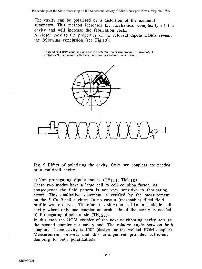
The cavity can be polarized by a distortion of the azimutal symmetry. This method increases the mechanical complexity of the cavity and will increase the fabrication costs. A closer look to the properties of the relevant dipole HOMs reveals the following conclusion (see Fig.10):
Instead of 4 HOM couplers, one can fix polarization of the mod!? and use only 2 couplers.at such position that each one couples to both polarization.
Fig. 9 Effect of polarizing the cavity. Only two couplers are needed or a multicell cavity.
a) Non propagating dipole modes (TE111, TM 1 1 0) : These two modes have a large cell to cell coupling factor. As consequence the field pattern is not very sensitive to fabrication errors. This qualitative statement is verified by the measurement on the 5 Cu 9-cell cavities. In no case a (reasonable) tilted field profile was observed. Therefore the situation is like in a single cell cavity where only one coupler on each side of the cavity is needed. b) Propagating dipole mode (TE 1 2 1 ) : In this case the HOM coupler of the next neighboring cavity acts as the second coupler per cavity end. The relative angle between both couplers at one cavity is 150" (design for the welded HOM coupler). Measurements proved, that this arrangement provides sufficient damping to both polarizations.
Proceedings of the Sixth Workshop on RF Superconductivity, CEBAF, Newport News, Virginia, USA
SRF93G01

1) Non propagating dipole modes: TElll and TMllO
All 5 copper models did not show any f i e l d unflatness:
- cel ls are well manufactured - cell to cell coupling is big:
k ,,,, ,= 10% and k,,,= 4.8 %
2) Propagating dipole modes: TE121
A m l 2 ~ 1 4 4 m 2 &,- )g,/4 256
Lower frequencies ( 6 untrapped m d e s ) :
- Qext 3 orders of mag. below required values.
Higher frequencies : - a l l propagating modes which have
stored energy in the beam t u b e s arc damped by 4 HOM couplers and couplers change polarization of the modes.
Fig. 10 Strategy to overcome the need of polarizing the cavity
4.4 Lorentz force detuning
The Lorentz force of the electromagnetic field with the surface currents deform the cavity wall and thus change the resonance frequency. The iris wall is bent inwards, the equator is bent outwards. Both result in lowering the resonant frequency. Fig. 11 plots this deformation as calculated for Eacc=25 MVIm and a wall thickness of 2.8 mm. The deviation is shown with an enhancement of a factor 1E5. The predicted frequency change is 1200 Hz. This has to be compared with the bandwidth of the cavity of 330 Hz (at Qext=3E6). Various stiffening schemes have been considered [2]. In
Proceedings of the Sixth Workshop on RF Superconductivity, CEBAF, Newport News, Virginia, USA
SRF93G01

the present layout the iris region is stabilized by a stiffening ring. Fig. 1 1 shows the design and the remaining deformation, equivalent to 320 Hz frequency change. It can be seen, that for further stabilization the region of the equator has to be made, stiffer.
3 equator equator
Fig. 1 1 Calculated effect of the Lorentz force to the cavity shape (at 25 MVIm, wall thickness 2.8 mm). Open line: originial shape, dark line: deformed shape (deviation enhanced by 1E5)
All above calculations have been done under the assumption that both ends of the cavity are hold fixed by the cryostat. A careful analysis of the rigidity of the LHe vessel concluded that considerable effort is needed here to keep the detuning of the cavity small enough by this effect .
Measurements of the Lorentz force detuning of a 9-cell TESLA cavity have not been done until the time of writing this paper. A comparison with calculated and measured data on similar cavities, however, confirms the validity of the codes used [9]. A strategy of frequency and phase control has been worked out to compensate the effect of detuning during pulsing one cavity [lo]. On the other hand, one klystron will power 16 different cavities. It remains to be demonstrated that the RF control system can handle this problem or whether further reduction of the Lorentz force detuning is required.
Proceedings of the Sixth Workshop on RF Superconductivity, CEBAF, Newport News, Virginia, USA
SRF93G01

5. Conclusion
The electrical design of the TESLA cavity has been finished. The major aim of the design was to reduce field emission by a low Epeak value and increase the number of cells to the maximum value allowed. Other properties like higher order mode damping, fundamental shunt impedance or cell to cell coupling were optimized at the same time, too. The detuning of the cavity by the Lorentz force was intensively investigated by calculations. The proposed stiffening scheme has to be verified by experiments.
Acknowledgements
Fruitful discussions with many members of the TESLA collaboration are greatfully acknowledged. Special thanks are given to A. Mosnier, J. Sekutowicz and H. Kaiser for extensive exchange of experience.
References
[I] Proceedings of the "First International TESLA Workshop", July 1990, Cornell. Editor H. Padamsee
[2] H. Kaiser, this conference [3] F. Dylla, to be published in Proceedings of IEEE Particle
Accelerator Conference, 1993, Washington [4] C.H. Rode, D. Proch, Proceedings of the 4th Workshop on RF
Superconductivity, KEK, 1989, Editor Y. Kojima, p. 75 1 [5] G. Geschonke, D. Proch, Proceedings of LC92, Garmisch
Partenkirchen, 1992, p. 407 [6] H. Padamsee, private communication [7] J. Sekutowicz, this conference [8] J. Sekutowicz, to be published in Particle Accelerators [9] A. Mosnier, TESLA Report 93-10 [ lo] H. Henke, B. Littmann, TESLA Report 93-12
Proceedings of the Sixth Workshop on RF Superconductivity, CEBAF, Newport News, Virginia, USA
SRF93G01


![Superconducting TESLA cavities - CERN · set for the TESLA Test Facility (TTF) linac [2]. The TESLA cavities are quite similar in their layout to the 5-cell 1.5 GHz cavities of the](https://img.pdfslide.us/doc/110x75/5f08b08b7e708231d4233ee5/superconducting-tesla-cavities-cern-set-for-the-tesla-test-facility-ttf-linac.jpg)