Embed Size (px)
Citation preview

' I
NASA Contractor Report 4084
The Surface Properties of Carbon Fibers and Their Adhesion to Organic Polymers
w. E. Bascorr, and L. T. Drza!
CONTRACT NAS1-17918 JULY 1987
https://ntrs.nasa.gov/search.jsp?R=19870016001 2018-05-07T05:56:08+00:00Z

NASA Contractor Report 4084
The Surface Properties of Carbon Fibers and Their Adhesion to Organic Polymers
W. D. Bascom Hercu Zes Aerospace Magna, Utah
L. T. Drzal Michigan State University East Lansing, Micbigan
Prepared for Langley Research Center under Contract NAS1-17918
National Aeronautics and Space Administration
Scientific and Technical Information Off ice
1987

Table of Contents
Page
I Introduction . . . . . . . . . . . . . . . . . . . . . . . . . . 1
I1 State-of-Knowledge of Carbon Fiber Surfaces . . . . . . . . . . 4
A Carbon Fibers . Structure and B u l k Properties . . . . . . . . 4
B Carbon Fiber Surface Treatment and Sizing . . . . . . . . . . 20
C Surface Characterization Techniques . . . . . . . . . . . . . 23
1 Microscopy . . . . . . . . . . . . . . . . . . . . . . . . 23
2 Surface Spectroscopies . . . . . . . . . . . . . . . . . . 26
3 Wetting Measurements . . . . . . . . . . . . . . . . . . . 30
4 Direct Chemical Analysis . . . . . . . . . . . . . . . . . 32
5 Other Techniques . . . . . . . . . . . . . . . . . . . . . 33 D Carbon Fiber Surface Properties . . . . . . . . . . . . . . . 34
1 Surface Morphology . . . . . . . . . . . . . . . . . . . . 34
2 Surface Chemistry . . . . . . . . . . . . . . . . . . . . 38
3 Surface Free Energy . . . . . . . . . . . . . . . . . . . 41
I11 State-of-Knowledge of Carbon Fiber Adhesion t o Polymers . . . . 43
A Adhesion vs Bond Strength . . . . . . . . . . . . . . . . . . 43
B Adhesive Interfacial Shear Strength . . . . . . . . . . . . . 53
C Adhesive Tensile Strength . . . . . . . . . . . . . . . . . . 59
D Polymer Properties Near the Interface . . . . . . . . . . . . 60 E Interfacial Processing Conditions . . . . . . . . . . . . . . 65 F Fiber/Matrix Adhesion and Composite Mechanical Properties . . 68

Page
I V C r i t i c a l Issues . . . . . . . . . . . . . . . . . . . . . . . . 73
A Propert ies o f Carbon F i b e r Surfaces . . . . . . . . . . . . . 74
B Propert ies o f the M a t r i x . . . . . . . . . . . . . . . . . . 78
C Propert ies o f the Interphase . . . . . . . . . . . . . . . . 79
V Conclusion and Recommendations . . . . . . . . . . . . . . . . . 81
V I Appendix . . . . . . . . . . . . . . . . . . . . . . . . . . . . 83
V I 1 References . . . . . . . . . . . . . . . . . . . . . . . . . . . 86
i v
.

I INTRODUCTION
The purpose o f t h i s r e p o r t i s t o document t h e s t a t e o f knowledge o f t h e
su r face p r o p e r t i e s o f carbon f i b e r (CF) and t h e p r o p e r t i e s o f t h e i n t e r f a c e
between carbon f i b e r and polymers w i t h emphasis on t h e f i b e r / m a t r i x
adhesion i n carbon f i b e r r e i n f o r c e d p l a s t i c s (CFRP). The r e p o r t i s an I
I
j ou tg rowth o f a conference h e l d a t NASA Larigley Research Center on December
10-12, 1985 which had been c a l l e d t o rev iew t h e problem o f low bond
s t r e n g t h between carbon f i b e r s and c e r t a i n t h e r m o p l a s t i c po lymers . The
conferees i nc luded a s m a l l g roup of s p e c i a l i s t s i n composite m a t e r i a l s ,
su r face chemis t ry , and composite mechanical behav io r and were drawn f rom
government, academe and i n d u s t r y (Appendix I).
It was e v i d e n t a t t h e c l o s e o f t h i s meet ing that t h e r e i s a se r ious
I l a c k o f knowledge n o t o n l y about CF adhesion t o t h e r m o p l a s t i c s but on t h e
n a t u r e o f t h e CF su r face i t s e l f and i t s i n t e r f a c e w i t h a l l c lasses o f
po lymers. Consequently, t h i s r e p o r t draws n o t o n l y on t h e d i s c u s s i o n
genera ted a t t h e meet ing a t Langley but a l s o on t h e a v a i l a b l e i n f o r m a t i o n
i n t h e open l i t e r a t u r e and f rom p r i v a t e d i scuss ions w i t h peop le work ing on
carbon f i b e r composites.
I n t h e search f o r improved de lamina t ion r e s i s t a n c e i n cont inuous CF
r e i n f o r c e d composites t h e impor tance o f m a t r i x f r a c t u r e energy has become
e v i d e n t (1) and has prompted i n t e r e s t i n using t h e i n h e r e n t l y h i g h f r a c t u r e
energy t h e r m o p l a s t i c s as m a t r i x r e s i n s . However, i t was d i scove red that

I
t h e tough the rmop las t i c polymers that had t h e o t h e r necessary requ i rements
f o r a m a t r i x i n s t r u c t u r a l components (e .g . , s o l v e n t res i s tance , high
modulus, and high Tg) do not have t h e bond s t r e n g t h t o carbon f i b e r s
e q u i v a l e n t t o that o f t h e the rmose t t i ng polymers such as t h e epox ies and
p o l y e s t e r s ,
The problem became e s p e c i a l l y e v i d e n t i n t h e NRSA/Langley program on
t h e micromechanics o f d e l a m i n a t i o n when a s e r i e s o f t h e r m o p l a s t i c polymers
were se lec ted t o model d i f f e r e n t modes o f m a t r i x f a i l u r e .
e l e c t r o n microscopy (SEM) o f t h e f r a c t u r e sur faces o f composites revea led
evidence o f low f i b e r / m a t r i x adhes ion .
Scanning
Table 1-1 l i s t s t h e r m o p l a s t i c po lymers known t o e x h i b i t poo r adhes ion
t o carbon f i b e r based on f r a c t o g r a p h i c (SEM) examinat ion i n d i c a t i n g an
absence o f polymer on t h e f i b e r s compared t o a s i m i l a r CF/epoxy m a t r i x
f r a c t u r e su r face . R lso l i s t e d i n Tab le 1-1 a r e t h e c r i t i c a l aspec t r a t i o s
(Rc/d) measured u s i n g a s i n g l e f i b e r shear adhes ion t e s t desc r ibed
l a t e r ( S e c t i o n 1114). The c r i t i c a l aspec t r a t i o i s an i n v e r s e f u n c t i o n o f
f i b e r r e s i n adhesion f o r a g i v e n f i b e r s t r e n g t h (a ) and f i b e r d iamete r f
(d) *
2

Table 1-1
Thermoplast ic Polymers Which E x h i b i t
Poor Adhesion t o AS4 Carbon F i b e r
Polymer _.I._ C r i t i c a l Asp2ct R a t i o , kc@
Po lye the re the rke tone*
Polyphenylene s u l f i d e *
Polycarbonate
Polypheny l e n e o x i d e
Po 1 ye t h e r im ide
Po ly s u l f o n e
( t y p i c a l epoxy)*
_.
106
125
93
121
60
-...-
* Adhesion can be s i g n i f i c a n t l y improved by p r o p r i e t a r y methods
W . 0. Bascom and L. W . Cordner, NASA C o n t r a c t NAS1-17918
W E p o n 828/m-PDA ( re fe rence 48)
I n t h e d i s c u s s i o n o f t h i s problem a t t h e Langley meet ing i t became
e v i d e n t that t h e r e was i n s u f f i c i e n t i n f o r m a t i o n about t h e CF s u r f a c e
p r o p e r t i e s and CF/polymer adhesion t o adequate ly e x p l a i n t h e adhesion
problems t o t h e r m o p l a s t i c s .
b r o a d l y grouped i n t o ;
The key ques t i ons brought f o r th can be
3

0 chemical and morpho log ica l c h a r a c t e r o f CF sur faces
0 p h y s i c a l and chemica l n a t u r e o f t h e CF/polymer i n te rphase
f a c t o r s that i n f l u e n c e adhes ion between CF and polymers
t h e e f f e c t o f CF/matrix adhes ion on lam ina te mechanica l p r o p e r t i e s
The scope o f t h i s r e p o r t i s t o r e v i e w t h e s t a t e o f knowledge i n these
key areas, i d e n t i f y s p e c i f i c ques t ions , and suggest research areas that
c o u l d s i g n i f i c a n t l y improve t h e unders tand ing o f these i ssues . A
comprehensive d i s c u s s i o n o f a l l aspec ts o f CF su r face p r o p e r t i e s and
adhesion i s beyond t h e scope o f t h i s r e p o r t but i n many ins tances t h e
reader i s d i r e c t e d t o s p e c i f i c re fe rences f o r d e t a i l e d i n f o r m a t i o n .
I T STATE-.OF-KNOWLEDGE OF CARBON FIBER SURFACES
A . Carbon F i b e r s - S t r u c t u r e and Bu lk Properti-e?
The carbon f i b e r re in fo rcemen t used a lmos t e x c l u s i v e l y i n s t r u c t u r a l
a p p l i c a t i o n s today i s made by t h e o x i d a t i o n / c a r b o n i z a t i o n of
p o l y a c r y l o n i t r i l e (PAN) f i b e r . Consequently, t h e d i s c u s s i o n he re i s
r e s t r i c t e d t o PAN-based CF. The b a s i c s t r u c t u r e o f PAN i s ;
4

CH CH2 - ,CH2 CH 2 ‘CH’ \CH’ 2‘CH ’
I CN
I C N
polyacrylonitrile
which is oxidized at temperatures of about 2OOOC to a ladder polymer
structure according to the scheme shown in Figure 11-1. The anion X
is presumed to be present; as an impurity in the PflN precursor.
Subsequent heat treatment at temperatures up to 1000°C and higher
results in a polyaromatic structure as shown in Figure 11-2. These
are highly idealized schematics but serve to illustrate that
graphitic structures can form at least over limited spatial regions.
The resultant fiber is generally described as a columnar
arrangement of misoriented turbostratic graphite crystallites. It is
generally agreed that the degree of graphitization and crystalline
organization is increased with increasing carbonization temperature.
However, because of crystal misalignment and the presence of
non-graphitized structure, these fibers are generally referred to as
carbon rather than graphite fibers.
5

::@ H H H
X YWy: H H H
Figure 11-1 Schematic o f the oxidat ion o f PFIN precusor to a ladder polymer ( 2 )

N H - 8 / \
H
ti r3 I \
400-6OO'C 1 -&hydrogem t ion
600- 1300'C 1 0cn4 trogcnrt ion
Figure 11-2 Schematic of graphitization o f oxidized PAN (3)
7

Various models o f t h e i n t e r n a l s t r u c t u r e o f carbon f i b e r have been
suggested based on high r e s o l u t i o n microscopy, e l e c t r o n and X-ray
d i f f r a c t i o n , neut ron s c a t t e r i n g and o t h e r techn iques . C u r r e n t t h i n k i n g
favors l o c a l i z e d f i b r i l l a r s t r u c t u r e s which arc! o rgan ized i n t o w r i n k l e d
and d i s t o r t e d r ibbons and sheets as shown i n F i g u r e 11:-3. One f e a t u r e o f
t h e s t r u c t u r e i n F i g u r e 11-3 i s t he sk in-core arrangement. The o u t e r
layers ( s k i n ) a r e more organ ized than t h e i n t e r i o r ( c o r e ) . The r e l a t i v e
p r o p o r t i o n o f s k i n t o core appears t o be a f u n c t i o n o f t h e f i n a l
ca rbon iza t i on temperature - high temperatures l e a d i n g t o t h i c k s k i n
s t r u c t u r e . (5)
C r y s t a l l i t e d imens iona l parameters have been measured u s i n g X-ray
d i f f r a c t i o n , e l e c t r o n d i f f r a c t i o n and n e u t r o n s c a t t e r i n g . These
parameters a r e t h e c r y s t a l l i n e s t a c k i n g th ickness , L and t h e average
l a y e r width L as shown i n F i g u r e 11-4. These c r y s t a l l i t e dimensions
C
ap
vary with t h e process ing c o n d i t i o n s a s shown i n Tab le 11-1‘’). Note i n
Table 11-1 t h e marked e f f e c t on c r y s t a l l i t e s i z e o f a p p l y i n g s t r e s s t o t h e
f i b e r d u r i n g process ing .
8

Figure 11-3 Carbon fiber three-dimensional model (4)

I A C
I
200 i t I
Figure 11-4 Crystallite dimensional parameters (6)
10
a

Table 11-1
C r y s t a l l i t e Dimensions o f PAN Carbon Fibers
(Reference 7)
Heat Treatment
Temperature
0
1.000
1400
2000
2400
2800
2250a
2500b
Lc
0
1 .o
1.8
3.4
4.0
6.0
20.0
5.7
1 aP
0
2.0
3.5
5.4
6.21
7.0
50.0
4.6
a
'Con t r o 1
Stress graphit ized
U n t i l very recently PAN-based f ibers have been c l a s s i f i e d i n t o two
categories; Type I (high modulus) and Type 11 (high strength). The range
o f properties of these f i b e r types are l i s t e d i n Table 11-2.
11

T a b l e 11-2
Carbon F i b e r C l a s s i f i c a t i o n
Heat: Treatment Temperature Modulus T e n s i l e S t r e n g t h l o n g Range Order IYPS. ---"""""-.o" -..--__-_ -.--.- GN/m2 I" ......-- GN/m2----".* ............................
1 I1
> 2000 -1500
3 10-517 1.68-1.45 145-276 2.35-3.10
high low
Over t h e p a s t few years f i b e r c l a s s i f i c a t i o n has become l e s s c l e a r c u t
due p r i m a r i l y t o i n d u s t r i a l demands f o r a "balance" o f mechanical
p r o p e r t i e s . Tab le 11-3 l i s t s some c u r r e n t f i b e r t ypes used f o r s t r u c t u r a l
a p p l i c a t i o n s .
The f i b e r c l a s s i f i c a t i o n s i n Tab le 11-3 c l e a r l y o v e r l a p which r e f l e c t a
demand f o r a m i x o f p r o p e r t i e s and t h e f a c t that f i b e r development i s i n an
e v o l u t i o n a r y s tage . C u r r e n t l y , t h e i n t e r m e d i a t e modulus I M f i b e r s a r e i n
g r e a t e s t demand s i n c e they o f f e r high s t r e n g t h , s t i f f n e s s , and e l o n g a t i o n .
However, t h e a i r f r a m e and m i s s i l e i n d u s t r i e s a r e l o o k i n g t o t h e carbon
f i b e r manufacturers f o r even b e t t e r performance; a 7 . 0 GN/M (1000 k s i )
s t r e n g t h f i b e r w i t h 2% e l o n g a t i o n and a modulus o f 345 GN/m
h i g h e r .
and i t i s o n l y a m a t t e r o f t i m e b e f o r e these l a b o r a t o r y processes a r e
scaled up t o p r o d u c t i o n l e v e l .
2
2 (50 M s i ) or
F i b e r s w i t h t hese p r o p e r t i e s have been r e a l i z e d i n t h e l a b o r a t o r y
12

Table 11-3
C u r r e n t State-of- the-f i r t Carbon F i b e r s
(Tow Test Data)
Modulus F i b e r Typ2 -*....- GN/m2
U l t r a High Modulus 524
High Modulus (Type I) 350-360
I n t e r m e d i a t e Modulus 280-310
Tens i l e Tens i l e E l o n g a t i o n
I_- S t r e n q t h GN/m2 -..-.xQ .....--
2 . 1 0 . 4
2 . 5 0 . 7
4.8-5.5 1.8-1.95
High E l o n g a t i o n 240-260 4.5-4.8 1 -90-2.0
- Examp .......- l e s
P 7 5 ( 4
IM-6 ( b, IM-7(b) HiTex 42(d) Toray 40(")
FlS-6( b, 'Toray 700(e)
I n t e r m e d i a t e 235 S t r e n g t h (Type 11)
4 . 1 1.5-1.7
-...1_1_
(a) fimoco Chemicals Corp. (b) Hercu les I n c . (c) BFlSF F i b e r s (d) Owens Corn ing F i b e r g l a s s Corp. (e) Toray I n d u s t r i e s I n c . , Osaka, Japan
I t should be emphasized that t h e mechanical p r o p e r t y data depend ve ry
much o n t h e way t h e f i b e r i s t e s t e d . B a s i c a l l y t h e r e a r e t h r e e methods o f
d e t e r m i n i n g t h e u n i d i r e c t i o n a l Oo p r o p e r t i e s o f CF; s i n g l e f i b e r t e n s i l e
t e s t s , t o w t e s t s , and lam ina te t e s t s . S i n g l e f i b e r t e s t s a r e ted ious ,
p r o v i d e o n l y s t r e n g t h data, and a r e seldom r e p o r t e d excep t as research
r e s u l t s . I n F i g u r e 11-5 s i n g l e f i b e r data a r e presented as a W e i b u l l
d i s t r i b u t i o n o f t e n s i l e s t r e n g t h s . The data d i s p e r s i o n i s t y p i c a l o f any
1 3

b r i t t l e f i b e r f o r which t h e s t r e n g t h i s determined by a d v e n t i t i o u s f l a w s ,
Carbon f i b e r t e n s i l e s t r e n g t h s a r e more commonly r e p o r t e d as tow data o r as
Oo laminate data. Impregnated tows f r o m 1000 t o 12,000 f i l a m e n t s a r e
p u l l e d th rough a l i q u i d epoxy and t h e n a d i e t o bring t o a p r e d e t e r m i n e d
f i b e r volume f r a c t i o n , V f .
l eng ths (ASTM D4018-81). Laminates a r e prepared by p rep reg l a y u p a c c o r d i n g
t o ASTM D3039 (prepreg sheets o f f i b e r impregnated w i t h uncured r e s i n ) .
Tow and lam ina te data a r e presented as W e i b u l l p l o t s i n F i g u r e s 11-6 and
11-7. FI comparison o f Oo t e n s i l e p r o p e r t i e s i s presented i n T a b l e 11-4
( d a t a f rom F i g s . 11-5, 6 and 7 ) .
The r e s i n i s cured arid t h e n t e s t e d i n 6-8in.
T a b l e 11-4
E f f e c t o f Test Method on Tensi le Strength (a,)
o f IM-6 Carbon F i b e r
S i n q l e F i l amen t Test*
2 GN/m
SD I -af
4.24 1.15
Tow T e s t ( 8 1 w Oo Laminate T e s t ( 8 ) w
GN/m2 GN/m2
SD .- -af SD - -af
5.35 0 . 2 8 4.84 0 .19
W a r r e n Schimpf, Hercules I n c .
#data normal ized t o 100% Vf
14

+++
I U c
cn m m m m \D
_- -1 Z66
+ ++ ++
+ ++ +
+ +
Zl8 1 599
ooz
99 T
+ I 15

Tow Test
(IM6/Unsized)
98.9
80.8
45.5
20 ,
"1 3 . 0
B" at
t 4-
t 4
t
t 4-
0 CJ r-
0 ur b
0 a, r-
U e a
Tensile Strength
(ksi)
Figure 11-6 Tow tensile strength data for IM-6 fihers in diglycidylether epoxy cured with an aromatic amine mixture. Fiber volume normalized to 100%
(Bascorn, W . D. and Hummel, K.; Hercules Inc. unpublished data)
16

Laminate Tensile Strength (IM6/Unsized)
98.9
80.8..
45.5"
20.0"
7.9"
3 . a
-
1 - 1 b W ci 03 0 c.
t 0 W
4
t t +
t t
t
Figure 11-7 Laminate (OO) tensile strength data for IM-6 fiber in Hercules 2502 resin. Fiber volume normalized to 100%
(Bascorn, W. D. and Hummel, K.; Hercules InC. Unpublished data)
17

Tab le 11:-5
E f f e c t o f M a t r i x Resin F r a c t u r e Energy
* on Oo Laminate T e n s i l e P r o p e r t i e s
Proper ty @ FJ
Oo T e n s i l e S t r e n g t h
( GN/m2)
**
I.. M a t r j x Resin-
DR-4 .-.I_
--...- 3501-6 _.- DR-1 DR-2 DR-3
4 . 2 1 4.29 5 .00 4.98 4.92
Oo T e n s i l e Modulus ** (GN/m2) 24 1 238 285 27 1 246
Oo T e n s i l e E l o n g a t i o n
(%I 1.55 1.79 1.79 1 . 8 1 1.94
Resin F r a c t u r e Energy
( J/m2) 74 507 734 787 1102
**Normalized to 100% Fiber Volume
18

The r e s u l t s i n Tab le 11-4 c l e a r l y i n d i c a t e t h e e f f e c t o f t e s t method on
Oo mechanica l p r o p e r t i e s . S i n g l e f i b e r t e s t s p r o v i d e e s s e n t i a l i n f o r m a t i o n
about t h e f i b e r i t s e l f - t h e n a t u r e of' t h e f l a w t ypes and d i s t r i b u t i o n .
However, r e s u l t s f rom tow and l a m i n a t e t e s t i n g a r e composite data and a r e
more p e r t i n e n t t o end-use purposes; tow data i s sought as a measure o f hoop
s t r e n g t h by t h e m i s s i l e community whereas l am ina te data i s used by t h e
a i r f rame i n d u s t r y where s t r u c t u r e s are most o f t e n f a b r i c a t e d by prepreg
layup .
In e v a l u a t i n g t e n s i l e p r o p e r t i e s , it i s obv ious that i n o r d e r t o make
r a t i o n a l comparisons t h e t e s t method must be s p e c i f i e d . Another
c o n s i d e r a t i o n i s that tow and laminate data a r e u s u a l l y normal ized t o some
c o n s t a n t f i b e r volume (V ), 65% o r loo%, which can f u r t h e r confuse
comparisons.
no rma l i zed t o 100% V f .
t o a f f e c t t e n s i l e s t r e n g t h . I n Tab le 11-5 data a r e presented f o r t h e
t e n s i l e s t reng ths and e l o n g a t i o n o f f i b e r s f rom a s i n g l e p r o d u c t i o n l o t
t e s t e d i n r e s i n s that were fo rmula ted t o have i n c r e a s i n g f r a c t u r e energ ies
by a sys temat i c i nc rease i n t h e amount o f a homogenous p l a s t i c i z e r . T h i s
sampling o f data suggests that t h e f i b e r e x h i b i t s i n c r e a s i n g s t r e n g t h and
e l o n g a t i o n w i t h i n c r e a s i n g r e s i n toughness. The s i t u a t i o n i s n o t as s imp le
as Tab le 11-5 might suggest i n that o t h e r r e s i n p r o p e r t i e s can i n f l u e n c e
t h e t e s t r e s u l t s . Nonetheless i t i s c l e a r that f i b e r t e n s i l e t e s t i n g i s by
no means independent of t h e r e s i n ma t r i x o r t e s t method;
f
I n Tab le 11-3 a l l t h e data a r e f r o m tow t e s t i n g and a r e
Moreover, t he cho ice o f m a t r i x r e s i n a l s o appears
19

The advances that have been made i n CF p r o p e r t i e s , e s p e c i a l l y o v e r t h e
l a s t f i v e years, a r e t h e r e s u l t o f t h e f o l l o w i n g f a c t o r s ;
changes i n t h e chemis t ry o f t h e PAN p r e c u r s o r
improvement i n t h e q u a l i t y o f t h e PAN p r e c u r s o r e s p e c i a l l y w i t h
rega rd t o d e f e c t s
i n t r o d u c t i o n o f f i b e r s t r e t c h a t v a r i o u s stages o f f i b e r p r o d u c t i o n
improved su r face trGatinent methods
cont inuous E b a t c h f i b e r p r o d u c t i o n ( l e s s post-manufacture damage)
improved f i b e r s i z i n g s
F i b e r Sur face Treatment and S i z i n g B * - -.....--.-.-----.-..-----̂-.---.---
It has been r e a l i z e d s i n c e t h e f i r s t development work on carbon f i b e r
tha t laminate p r o p e r t i e s , e s p e c i a l l y under shear l oad ing , c o u l d be
d r a m a t i c a l l y improved by an o x i d a t i v e s u r f a c e t rea tmen t . There i s a l a r g e
body of l i t e r a t u r e on t h e e f f e c t of these t rea tmen ts on t h e sur face
p r o p e r t i e s o f t h e f i b e r and on lam ina te s t r e n g t h . T h i s s u b j e c t i s
discussed i n more d e t a i l i n l a t e r s e c t i o n s o f t h i s r e p o r t . It i s g e n e r a l l y
thought that t h e sur face t rea tmen t " a c t i v a t e s " t h e su r face t o improve
20

adhesion to matrix polymers primarily by introducing oxygen functionality
for interfacial reactions. This is probably a simplistic picture. The
most commonly used surface treatments are air oxidation and electrolysis
which lend themselves to continuous production but the details of these
industrial processes are proprietary.
Sizing of carbon fiber involves application of an organic film (usually
polymeric) to protect the fiber during fabrication into structures. The
amount of sizing varies between 0.5-1.5 wt % of the fiber depending on the
fiber type and its intended purpose. Occasionally, surface treatment and
sizing are confused and thought to be synonymous; clearly they are not.
Sizings are applied to hold fiber bundles (tows) together and provide some
protection during processing. Filament winding of CF is especially
aggressive in that the tows are held under tension as they pass through
eyelets and over guides. Sizings for filament winding tend to encapsulate
the tow and hold it as a relatively cohesive bundle. Clt the same time, the
sizing must be sufficiently friable to allow the tow to be opened up and
readily impregnated by the liquid resin. Similar requirements are
necessary for the weaving of carbon fiber tows and often the same sizing is
used for both weaving and filament winding. In prepregging operations, the
tows are collimated and brought into contact with pre-filmed resin, often
between nip rolls. This is a less aggressive process than filament winding
or weaving so that prepreg sizings leave the fiber tow less encapsulated
and more flexible. The role o f sizing for prepreg is primarily to hold
down loose fiber ends which otherwise become misaligned in the prepreg
21

sheet o r break l oose and g a t h e r i n to s m a l l bundles o f t e n r e f e r r e d t o as
"comets."
o r comets have any s i g n i f i c a n t e f f e c t o n l am ina te mechanical p r o p e r t i e s .
Nonetheless, they d e t r a c t f rom t h e cosmet ic appearances o f t h e p rep reg and
they may i n t e r f e r e w i t h high r a t e p r o d u c t i o n equipment such as au tomat i c
tape l a y i n g machines that a r e r a p i d l y b e i n g i n t r o d u c e d i n t o t h e a i r f r a m e
i n d u s t r y .
I t i s p r o b l e m a t i c a l whether a s m a l l number o f m i s a l i g n e d f i b e r s
There i s no c l e a r c u t evidence that t h e commerical s i z i n g s c u r r e n t l y
a p p l i e d t o carbon f i b e r f o r epoxy/matr ix composi tes s i g n i f i c a n t l y improve
laminate mechanical p r o p e r t i e s . I n f a c t , i n d e v e l o p i n g s i z i n g s f o r
improved p rocess ing one o f t h e c r i t e r i a i s that t h e s i z i n g agent n o t have a-
s e r i o u s l y adverse a f f e c t on l am ina te p r o p e r t i e s . I n a r e c e n t s tudy a
comparison was made o f t h e l am ina te p r o p e r t i e s u s i n g uns i zed CF w i t h
laminates prepared u s i n g f i v e d i f f e r e n t epoxy-compatible s i z i n g s . I t was
found that t h e s i z i n g s had no a f f e c t on l a m i n a t e p r o p e r t i e s compared t o t h e
uns ized f i b e r . I n t h i s s tudy t h e data sampl ing was l a r g e enough t o show
that any apparent e f f e c t s o f s i z i n g were w i th in t h e normal data s c a t t e r and
n o t s t a t i s t i c a l l y s i g n i f i c a n t . However, t h e r e have been r e p o r t s where t h e
s i z i n g does have an e f f e c t on l a m i n a t e p r o p e r t i e s '
l a t e r s e c t i o n (III-D) evidence i s p resen ted that r e s i n c o a t i n g s on CF can
s i g n i f i c a n t l y a f f e c t f i b e r - m a t r i x adhesion. However, s i z i n g agents
p r e s e n t l y i n commercial use a r e des igned f o r p rocess ing and n o t t a i l o r e d t o
enhance lam ina te p r o p e r t i e s .
*
I . Indeed, i n a
h Bascom, W. D. and H u m l , K.; Hercules Inc. unpublished data
22

C. Surface C h a r a c t e r i z a t i o n Techniques
The i n t e r a c t i o n o f a carbon f i b e r su r face w i t h a p o l y m e r i c m a t e r i a l
depends on t h e t o p o g r a p h i c a l fea tures o f t h e f i b e r su r face as w e l l as i t s
a tomic and molecu la r composi t ion.
f r o m l e s s than t e n t o o v e r a thousand nanometers.
o f t h e f i b e r su r face can c o n s i s t o f weakly adsorbed m a t e r i a l wh ich can be
removed by t h e a p p l i c a t i o n o f thermal energy a s w e l l as s t r o n g l y adsorbed
m a t e r i a l which i s chemica l l y a t tached t o t h e f i b e r su r face w i t h s t rong
c o v a l e n t bonds.
f i b e r - m a t r i x i n t e r a c t i o n and t h e r e f o r e b o t h m u s t be comple te ly
c h a r a c t e r i z e d . f l wide v a r i e t y o f microscopic , spec t roscop ic and
thermodynamic techniques a r e a v a i l a b l e which a r e s u i t a b l e f o r t h i s t ype o f
c h a r a c t e r i z a t i o n .
a n a l y s i s technique which by i t s e l f can g i v e t h e combina t ion o f p h y s i c a l ,
chemical , thermodynamic and topograph ica l i n f o r m a t i o n r e q u i r e d t o p rov ide a
f i r m b a s i s f o r unders tand ing t h e polymer-carbon f i b e r i n t e r f a c e . However,
s e l e c t i v e use of a combinat ion o f these techniques can p r o v i d e a complete
p i c t u r e .
Topographica l f e a t u r e s can range i n s i z e
The chemical compos i t ion
Both types o f m a t e r i a l a r e capable o f a f f e c t i n g t h e
I t should be po in ted o u t that t h e r e i s no s i n g l e sur face
1. Plicroscopy The most fundamental sur face c h a r a c t e r i z a t i o n
techn ique i s microscopy. O p t i c a l , scanning e l e c t r o n microscopy (SEM) and
t r a n s m i t t e d e l e c t r o n microscopy (TEM) o f f e r a s e t o f complementary
e x p e r i m e n t a l techniques which prov ide v a l u a b l e topograph ic i n f o r m a t i o n f rom
t h e macroscopic down t o t h e a tomic l e v e l .
23

O p t i c a l microscopy i s used t o p r o v i d e b a s i c i n f o r m a t i o n abou t t h e f i b e r
and i t s g e o m e t r i c a l c h a r a c t e r i s t i c s . F o r t h e t e n pm o r l e s s d i a n w t e r
carbon f i b e r s , o p t i c a l microscopy can p r o v i d e i n f o r m a t i o n abou t t h e f i b e r
d iameter and c ross -sec t i on and v a r i a t i o n i n d iamete r w i t h l e n g t h . The
upper l i m i t o f r e s o l u t i o n o f t h e o p t i c a l microscope i s about one-tenth o f a
m ic ron so f e a t u r e s l e s s than a m ic ron can not be w e l l c h a r a c t e r i z e d .
Scanning E l e c t r o n Microscopy uses e l e c t r o n s as t h e p r o b i n g medium and
t h e r e f o r e has a much h i g h e r l i m i t o f r e s o l u t i o n . Pr imary and secondary
e l e c t r o n s can be c o l l e c t e d a f t e r i n t e r a c t i o n w i t h t h e carbon f i b e r and used
t o r e c o n s t r u c t t h e image o f t h e s u r f a c e . The l a r g e dep th o f f i e l d
assoc ia ted w i t h t h e SEM observa t i ons make t h e s u r f a c e images ve ry
i n f o r m a t i v e . Features o f t h e f i b e r s u r f a c e down t o t h e 5 nanometer l e v e l
can be observed. A n a d d i t i o n a l advantage a s s o c i a t e d w i t h t h e l a r g e dep th
o f f i e l d is t h e a b i l i t y t o observe t h r e e d imens iona l f e a t u r e s on a
sur face. Sample stages man ipu la tab le i n t h r e e dimensions p r o v i d e complete
access t o any f e a t u r e o f t h e f i b e r topography.
Scanning e l e c t r o n microscopy o f CF i s l i m i t e d f o r most i ns t rumen ts by
"charging" o f t h e s u r f a c e . E l e c t r o n build-up on t h e r e l a t i v e l y low
c o n d u c t i v i t y f i b e r can s e r i o u s l y obscure sur face d e t a i l s .
overcome by t h e e l e c t r o d e p o s i t i o n of c o n d u c t i v e m e t a l c o a t i n g s ( e . g . , A u )
t o t h e s u r f a c e . However, as u s e f u l as t h e c o a t i n g s may be, t hey a r e 10-20
nm t h i c k and may obscure s m a l l s c a l e s u r f a c e f e a t u r e s .
T h i s problem i s
24

The Transmission Electron Microscope provides the highest resolution of
any of the microscopic techniques routinely available. The attainment of
this capability requires that the electron be transmitted through the
sample. The depth of penetration of an electron into a solid is limited by
the accelerating voltage. This limits the technique to either samples less
than one hundred nanometers in thickness or to replicas of the surfaces of
interest .
Replication of surfaces for TEM has been used for decades. CI composite
replica made from a thin polymer and surface coating is formed on the fiber
surface by deposition techniques and then removed intact for direct
observation in the TEM. Limitations of this approach are in the ability to
remove the replica intact and the generation of surface artifacts through
the replication process itself.
Direct 1EM observation of the fiber surface can be achieved through the
use of ultramicrotomy. Ultrathin samples, typically about 50 nanometers in
thickness, are cut from the sample. This involves encapsulating the carbon
fiber in a resin to immobilize it during the cutting process. A diamond
knife is passed through the sample and consecutive slices of material are
made, floated on the surface of a fluid and collected on an electron
microscope grid for direct TEM observation.
for fiber-matrix interfacial characterization by observing a through
thickness section that includes the fiber surface and adjacent regions.
This technique is very useful
25

Frac tu re events o c c u r r i n g b e f o r e sample m ic ro toming can be preserved f o r
l a t e r a n a l y s i s and t h e l ocus o f i n t e r f a c i a l f a i l u r e can be d e t e c t e d by t h i s
technique. L i k e any exper imen ta l t echn ique however, a r t i f a c t s a r e produced
i n t h e c u t t i n g process wh ich must be c h a r a c t e r i z e d and separated b e f o r e
i n t e r p r e t i n g t h e r e s u l t s .
2. Q.-face Spectroscopies Fundamental i n f o r m a t i o n abou t t h e a tomic
and molecular compos i t i on o f t h e f i b e r s u r f a c e can be ob ta ined th rough t h e
use of s u i t a b l e su r face spec t roscop ies .
bombarding t h e s u r f a c e o f i n t e r e s t w i t h a probe atom, i on , e l e c t r o n o r
photon. These species e i t h e r i n t e r a c t w i t h t h e s u r f a c e and a r e energy
analyzed o r cause t h e emiss ion o f s u r f a c e species which a r e c h a r a c t e r i s t i c - o f t h e s u r f a c e environment. Each spec t roscop ic techn ique has i t s own
advantages and l i m i t a t i o n s when a p p l i e d t o carbon f i b e r s .
These analyses opera te by
Auger E l e c t r o n Spectroscopy (AES) probes t h e s u r f a c e w i t h high energy
e l e c t r o n s . These e l e c t r o n s i n t e r a c t w i t h atoms a t and below t h e s u r f a c e
causing t h e emiss ion o f Auger e l e c t r o n s .
such as t o r e s t r i c t t h e i r em iss ion t o those i n t h e f i r s t t h i r t y o r f o r t y
a tomic l a y e r s o f t h e m a t e r i a l , The energy o f t h e Auger e l e c t r o n s i s
measured and u n i q u e l y r e l a t a b l e t o t h e h o s t atom f r o m which t h e e l e c t r o n
came. Q u a n t i t a t i o n o f t h e sur face a t o m i c compos i t i on and c o n c e n t r a t i o n can
be obta ined and i n some ins tances m o l e c u l a r i n f o r m a t i o n i s p o s s i b l e f rom
The energy o f t hese e l e c t r o n s i s
a n a l y s i s o f t h e data ( 9 ) .
26

As with any electron bombardment technique, electron induced surface
heating, desorption, etc. is possible coincident with the analysis. This
is much less likely in a conducting material or in a material that is
stable to high temperatures. While beam effects on carbon atoms in the
fiber are a remote possibility, desorption of physisorbed and chemisorbed
material is very likely rendering the analysis susceptible to changing
composition during the experiment. New advances which use a very narrow
focused beam which is scanned across the surface reduce the dangers of
surface change during analysis. Most of the published data on surface
analysis of carbon fibers using FiES has been collected with older model
instruments without the scanning capability and has been limited to
identification of atomic composition and concentration. Many of the
experimental limitations associated with sample heating, electron induced
desorption, etc. can be eliminated through the use of X-ray Photoelectron
Spectroscopy (XPS) also known as Electron Spectroscopy for Chemical
CInalysis (ESCA). X-ray photons are used as the probing species rather than
electrons as in CIES. These photons cause the ejection of core electrons
from atoms in the material under investigation. Because o f the short mean
free path for these core electrons, only electrons from the first few
atomic layers are able to escape from the surface to the collector. This
makes the analysis a surface sensitive technique. Since there are unique
binding energies associated with the molecular environment of each core
electron, in principle it is possible to determine the molecular
environment each electron came from. Counting techniques are quantitative
and surface concentrations can be accurately and reproducibly
determined (10) 27
Photon induced d e s o r p t i o n o f su r face spec ies a r e much l e s s l i k e l y than
e l e c t r o n induced e f f e c t s , consequent ly su r face changes induced during t h e
spread o f b i n d i n g energ ies f o r a l l carbon oxygen species f o r example covers
course o f t h e a n a l y s i s a r e l e s s l i k e l y w i t h XPS. Sample h e a t i n g i s a l s o
reduced because o f t h e lower power coupled t o t h e su r face .
C e r t a i n l i m i t a t i o n s do e x i s t however. The a b s o l u t e va lue o f t h e
I
I I
I o n l y 3 eV. I n p r a c t i c e , model s t u d i e s have been used t o q u a n t i t a t i v e l y
determine t h e mo lecu la r s t r u c t u r e (").
c o l l e c t e d can a r i s e f rom t h e su r face l a y e r as w e l l as f r o m up t o t e n a tomi?
l a y e r s below t h e su r face .
semiconductor such as carbon f i b e r . T h i s can be m i t i g a t e d by t h e use o f a I
f l o o d gun t o keep t h e su r face p o t e n t i a l o f t h e f i b e r s cons tan t . These
L ikewise , t h e pho toe lec t rons
Sample cha rg ing can be a problem f o r a I
I
f a c t o r s must be cons idered when t h e data i s reduced. F o r carbon f i b e r s ,
r e l a t i v e comparisons a r e s t r a i g h t f o r w a r d and a f i n i t e number of su r face
species and mo lecu la r s t a t e s e x i s t f o r t h e atoms t y p i c a l l y found on t h e
f i b e r sur faces .
I o n S c a t t e r i n g Spectroscopy (ISS) i s t h e t h i r d major su r face a n a l y s i s
technique. The mo lecu la r probe i n t h i s case i s an ion wh ich i s d i r e c t e d a t
t h e surface, loses energy during t h e c o l l i s i o n , and i s c o l l e c t e d and t h e
energy analyzed. ISS i s t r u l y a sur face s e n s i t i v e techn ique i n that o n l y
28

t h e a tomic environment o f t h e outermost su r face w i t h wh ich t h e i o n c o l l i d e s
determines t h e s c a t t e r i n g behav io r . The l i m i t a t i o n s o f t h e techn ique a r e
that o n l y a tomic i n f o r m a t i o n can be obta ined, t h e s e n s i t i v i t y f o r each
e lement v a r i e s across t h e p e r i o d i c char t , and t h e c o l l i s i o n process i t s e l f
causes some d e s o r p t i o n o f su r face species. Most a p p l i c a t i o n s t o carbon
f i b e r s have been used t o i d e n t i f y elements i n t h e ou termost su r face
l a y e r ( 12) .
P o s i t i v e and Negat ive Secondary I o n Mass Spectroscopy (+ o r - SIMS)
makes use o f t h e s p u t t e r i n g process t o cause removal o f t h e su r face a tomic
l a y e r i n a c o n t r o l l e d manner u s i n g acce le ra ted i o n s i n t h e same manner as
w i t h t h e I S S a n a l y s i s . I n t h i s case t h e s p u t t e r e d spec ies a r e c o l l e c t e d i n
a mass spect rometer wh ich has been b iased e i t h e r p o s i t i v e l y o r n e g a t i v e l y .
C rack ing p a t t e r n s hav ing un ique molecu la r c h a r a c t e r i s t i c s r e s u l t f r o m t h e
d e s t r u c t i o n o f pa ren t molecules i n a manner i d e n t i c a l t o that found i n a
mass spec t rometer . Simultaneous s o l u t i o n o f these s p e c t r a u s i n g known
c r a c k i n g p a t t e r n s g i v e s q u a n t i t a t i v e i n f o r m a t i o n about t h e i d e n t i f i c a t i o n
o f parrrnt sur face molecules and t h e i r c o n c e n t r a t i o n . The species de tec ted
a r e o n l y from t h e su r face l a y e r . The ma jo r l i m i t a t i o n s a r e that t h e
c r a c k i n g p a t t e r n s of t h e p a r e n t molecules must be known f o r t h e c o n d i t i o n s
o f t h e exper iment and that techniques l i k e ISS o r SIMS a r e d e s t r u c t i v e i n
that t h e sur face l a y e r i s b e i n g removed during t h e a n a l y s i s ,
O the r su r face techn iques e x i s t f o r t h e i d e n t i f i c a t i o n o f su r face
compos i t i on . The most n o t a b l e i s f o u r i e r t r a n s f o r m i n f r a - r e d
29

spectroscopy. A p p l i c a t i o n s o f t h i s mo lecu la r spect roscopy have l i m i t e d use
f o r carbon f i b e r s because o f t h e a d s o r p t i o n uf t h e i n t e r r o g a t i n g r a d i a t i o n
by t h e f i b e r and because o f t h e s m a l l sur face t o volume s i g n a l f o r t h e
f i b e r s themselves. Advances a r e o c c u r r i n g wh ich have t h e promise f o r
i nc reas ing t h e s e n s i t i v i t y o f t h e techn ique so that mo lecu la r i n f o r m a t i o n
about the su r face compos i t ion can be ach ieved.
3 . Wet t i nq Measurements A necessary c r i t e r i o n f o r a c h i e v i n g a s t a b l e
f iber -po lymer i n t e r f a c e i s that t h e s u r f a c e f r e e energy m u s t decrease when
t h e i n t e r f a c e i s formed. Sur face f r e e energ ies o f s o l i d s cannot be
c a l c u l a t e d f o r r e a l sur faces and cannot be measured d i r e c t l y . I n d i r e c t
measurements a r e p o s s i b l e however.
The c o n t a c t ang le wh ich a d r o p o f l i q u i d forms when p laced i n c o n t a c t
w i t h a sur face rep resen ts t h e e q u i l i b r i u m s t a t e between t h e l i q u i d and t h e
subs t ra te and can be used a s an i n d i c a t i o n o f c o m p a t a b i l i t y . I f t h e
c o n t a c t ang le 0 formed i s l e s s than 900 t h e n t h e su r face i s s a i d t o be
' w e t ' by t h e l i q u i d . I f t h e c o n t a c t ang le i s ze ro t h e l i q u i d i s s a i d t o
' spread ' on t h e s u b s t r a t e . Spreading i s more d e s i r a b l e than w e t t i n g a lone
a l though each insu res an acceptab le i n t e r f a c i a l f r e e energy f o r adhesion i n
that the thermodynamic work of adhes ion (W,) i s p o s i t i v e (see S e c t i o n
1114).
The measurement of c o n t a c t ang les on c y l i n d r i c a l f i b e r s of l e s s than
t e n microns i n d iameter p resents Some fo rmidab le exper imen ta l problems i f
30
done o p t i c a l l y .
f i b e r i n t o t h e l i q u i d o f i n t e r e s t and measuring t h e f o r c e o f immersion o r
emers ion. fl s imp le f o r c e balance a l l ows t h e c o n t a c t ang le t o be c a l c u l a t e d
fl v a r i a t i o n o f t h e technique i s p o s s i b l e by immersing t h e
i f t h e f i b e r pe r ime te r and sur face f ree energy o f t h e l i q u i d a r e known.
The f i b e r p e r i m e t e r can be c a l c u l a t e d d i r e c t l y u s i n g a l i q u i d w i t h a known
low s u r f a c e f r e e energy wh ich spreads on t h e f i b e r su r face and does n o t
f o r m a f i n i t e c o n t a c t ang le . The apparatus u s u a l l y employed f o r these
t e s t s i s t h e Wilhelmy balance descr ibed i n standard sur face chemis t ry
t e x t s ( 13,14)
f l d d i t i o n a l i n f o r m a t i o n c h a r a c t e r i s t i c o f t h e f i b e r su r face and
f i b e r - m a t r i x i n t e r f a c e i s p o s s i b l e us ing t h i s techn ique. I f a s e r i e s o f
l i qu ids o f s i m i l a r s t r u c t u r e and i n c r e a s i n g su r face f r e e energy i s used t o
measure t h e c o n t a c t angle, a p l o t o f t h e cos ine o f t h e c o n t a c t ang le versus
l i q u i d su r face f r e e energy w i l l r e s u l t i n a s t ra ight l i n e wh ich can be
e x t r a p o l a t e d t o cos 8 = 1 o r ze ro contac t ang le . T h i s p o i n t i s d e f i n e d
as t h e Zisman c r i t i c a l su r face tens ion o f t h e s o l i d o r t h e va lue o f t h e
s u r f a c e t e n s i o n below wh ich l i qu ids w i l l "spread" and above wh ich they w i l l
"wet" ( 15)
I f c o n t a c t ang les a r e measured us ing l i q u i d s w i t h d i f f e r e n t p o l a r and
d i s p e r s i v e c h a r a c t e r and t h e assumption made that t h e p o l a r and d i s p e r s i v e
components of t h e su r face f r e e energy a r e a d d i t i v e t h e n t h e p o l a r and
d i s p e r s i v e components o f t h e sur face f r e e energy o f t h e s o l i d can be
31

obta ined(16) . The assumptions wh ich a r e t h e b a s i s f o r t h i s d e t e r m i n a t i o n
a r e the s u b j e c t o f c o n t i n u i n g debate.
by the d e c l a r a t i o n that t h e nond ispe rs i ve f o r c e s can be c h a r a c t e r i z e d a s
CI re f inement t o t h i s process e x i s t s
b e i n g t h e sum o f a c i d and base i n t e r a c t i o n s . The measurement o f c o n t a c t
angles coupled w i t h t h e measurements o f t h e hea ts o f a d s o r p t i o n o f probe
l i q u i d s can p r o v i d e a measure o f t h e ac id /base c h a r a c t e r o f a s o l i d
sur face (17)
l h e s u r f a c e f r e e energ ies o f l i q u i d polymers can be measured d i r e c t l y
using a v a r i e t y o f techniques e i t h e r based on t h e same immersion techn ique
used f o r c o n t a c t ang les on f i b e r s o r t h rough d e t e r m i n a t i o n o f t h e shape o f
a molten d r o p o f polymer e i t h e r hanging o r r e s t i n g on a su r face *
.
From the s u r f a c e f r e e energy o f t h e polymer one can p r e d i c t i n t e r f a c i a l
c o m p a t a b i l i t y and thermodynamic e q u i l i b r i u m w i t h a s u b s t r a t e .
4 . D i r e c t Chemical CInalysis CI l a r g e body o f l i t e r a t u r e e x i s t s on t h e
chemical a n a l y s i s o f su r face groups on carbon f i b e r s . These techn iques
i n c l u d e acid-base t i t r a t i o n s , s p e c i f i c chemica l r e a c t i o n s such a s
diazomethane t o d e t e c t h y d r o x y l groups, and t h e use o f r a d i o t r a c e r l a b e l e d
reac tan ts . Ehrburger and Donnet (I8) found a s t r o n g c o r r e l a t i o n between
weak ac id groups (de tec ted by sodium e t h a n o l a t e ) on t r e a t e d f i b e r and
composite i n t e r l a m i n a r shear s t r e n g t h i n epoxy m a t r i x . The s u b j e c t has
been reviewed by Donnet and Bansa l (19) , but has been l a r g e l y superseded
by spect roscopic techn iques . O n i n t e r e s t i n g combina t ion o f "wet chemis t r y "
and spectroscopy i s t h e l a b e l i n g o f s u r f a c e groups w i t h heavy m e t a l i o n s
*see reference 14; pages 12 and 25
32

which are then analyzed by XPS or some other appropriate
spectroscopy (20) .
uncertainties as to the chemical specificity of the labeling ion.
However, as with chemical titration, there can be
5. Other Techniques Other methods of characterizing the molecular
surface environment of carbon fibers exist.
fiber surface can be determined by oxygen chemisorption measurements. A
fiber sample is heated in a high vacuum to temperatures at which surface
species are all removed. Careful introduction of oxygen into the sample
chamber and monitoring the amount chemisorbed either directly through
weight changes or indirectly through volumetric changes will allow
quantification of the chemisorption sites. Variation of the thermal
conditions associated with the chemisorption can be used to differentiate
site reactivities.
'The chemical reactivity of the
The desorption process itself provides much information about the
atomic and molecular character of the fiber surface. If a sample of carbon
fiber is confined to a vacuum chamber on which a mass spectrometer is
attached, identification of surface molecular species that desorb as a
function of temperature can be made ( 11,12). Weakly physisorbed material
is removed from the fiber surface at temperatures up to 150OC. This
material is always present on every fiber surface and if not removed
(21) properly can create interfacial voids during composite processing . At higher temperatures, surface chemical groups are desorbed. The type and
quantity of material volatilized at high temperatures provides information
on the chemical structure of the surface. 3 3

Measurements of specific heats of adsorption between probe molecules
and the fiber sites can be made either indirectly or directly. Adsorption
studies using gaseous molecules having functional groups can be conducted.
Distinction between physisorption and chemisorption can be made by checking
for reversibility of adsorption. Replicate isotherms determined at various
temperatures can be used to measure the heats of adsorption. An added
benefit of this measurement is the determination of the fiber surface area
through adsorption of inert gas molecules (11s12), Topographical changes
caused by surface treatments such as the creation of pores, cracks and
fissures can readily be detected.
Direct measurement of the heats of adsorption of model probe molecules
having the same functional groups as the polymer under investigation can be
conducted using calorimetry. Flow microcalorimetry can be conducted in
which small amounts of carbon fiber are confined to a sample chamber and
the heats of adsorption of various probes molecules can be determined
directly.
D . carbon Fiber Surface Properties
1. Carbon Fiber Surface Morpholoqy The surface properties of carbon
fibers are intimately tied to the internal structure of the fiber itself.
The basic building block of the fibers are the graphitic crystallites which
are formed during the conversion of the PAN based precursor to the carbon
3 4

fiber(**). This crystallite is in turn composed of layers of graphite
basal planes which are arranged turbostratically into a layered structure.
The size of these crystallites is governed by the time and temperature
conditions seen by the fiber as it is converted from PRN to carbon during
(23) the heat treatment step of its manufacture . longer residence times
coupled with higher graphitization temperatures in an inert environment
promote larger planar graphitic basal planes and larger layered
crystallites.
The crystallites themselves are arranged in a filamentary or
ribbon-like morphology roughly parallel to the fiber axis. Strain applied
during the processing steps and high temperature cause the axial alignment
of these fibrillar entities to become more perfect and parallel to the
fiber axis (Table 11-1).
The result of these mechanisms is that the high modulus fibers tend to
have surfaces that are predominantly composed of graphitic basal planes.
In the lower modulus fibers, produced at relatively low graphitization
temperatures, the orientation of the crystallites is altered to produce a
surface with less graphitic basal planes. The edges and corners of these
crystallites intersect the fiber surface in a greater percentage in the
lower modulus fibers.
This mechanistic model presents an ideal picture of the bulk and
surface structure of the carbon fiber after graphitization. The real
3 5

composi t ion o f t h e f i b e r sur face i s determined by t h e c a t a c l y s m i c events
which occur during t h e g r a p h i t i z a t i o n of t h e f i b e r .
t h e p o l y a c r y l o n i t r i l e polymer backbone and subsequent rearrangement o f t h e
carbon atoms i n t o t h e hexagonal g r a p h i t i c s t r u c t u r e i n v o l v e s t h e g e n e r a t i o n
and removal o f v o l a t i l e m a t e r i a l f r o m t h e i n t e r i o r a s w e l l as t h e s u r f a c e
o f t h e f i b e r . G r a p h i t i z a t i o n most p robab ly occurs f rom t h e s u r f a c e
inward. The escaping v o l a t i l e s must c o n t i n u o u s l y be t r a n s p o r t e d th rough
t h i s forming su r face l e a v i n g behind a ve ry d i s r u p t e d s t r u c t u r e . The
skin-core s t r u c t u r e observed f o r some carbon f i b e r s ( S e c t i o n 11-4) c l e a r l y
i nvo l ves two opposing processes, c o n s o l i d a t i o n o f t h e o u t e r l a y e r s and t h e
simultaneous d i s r u p t i o n o f these l a y e r s as v o l a t i l e s escape f r o m t h e
i n t e r i o r . Consequently, an as-formed carbon f i b e r w i t h o u t any t r e a t m e n t
whatsoever would be expected t o have a ve ry d e f e c t laden o u t e r s u r f a c e .
The decomposi t ion o f
Publ ished s t r u c t u r a l s t u d i e s c o n f i r m t h i s p i c t u r e . I t has even been
shown that a su r face l a y e r e x i s t s on t h e f i b e r s u r f a c e which appears t o be
q u i t e d i f f e r e n t m o r p h o l o g i c a l l y than t h e b u l k o f t h e f i b e r . (24)
Adsorp t i on t o o l s have been used t o probe t h e f i b e r s u r f a c e t o d e t e c t
cracks, pores and f i s s u r e s induced by f i b e r s u r f a c e t r e a t m e n t s . Prolonged
o x i d a t i v e t rea tmen ts do produce a l a r g e a r r a y o f cracks, pores and f i s s u r e s
wh ich d r a m a t i c a l l y i nc rease t h e f i b e r sur face area‘”). There i s an
accompanying l o s s i n f i b e r mechanica l p r o p e r t i e s w i t h these t rea tmen ts
wh ich i n d i c a t e s that t h e f laws genera ted a r e exceeding a c r i t i c a l s i z e .
However, t h e commercial t rea tmen ts e v i d e n t l y o p e r a t e w i t h o u t c r e a t i n g
c r i t i c a l f l a w s s ince f i b e r t e n s i l e s t r e n g t h s a r e n o t reduced a f t e r
commercial su r face t rea tmen ts , F i g u r e 11-8 ( 2 5 ) 36

c3 z w d w cn w - s cn
li
0
1 0 (v 4
0 0 r(
0 00
e 0
9
0 4
0 cv
!O
4
37

The presence of basal planes on the fiber surfaces has implications for
the surface chemical nature of the fiber surface. It has been shown that
the graphitic basal plane is very inert to chemical attack. The sites for
chemical attack of graphite are the edges and corners of the graphitic
crystallites and not the basal plane surface(26).
increase in basal plane orientation with increasing graphitization
temperature and therefore modulus, less potential sites for the addition of
chemical functionality exist on the higher modulus fibers than on the lower
modulus material.
Because of the
2 . Carbon Fiber Surface Chem,istry. The main atomic constituent of the
carbon fiber surface is carbon.
assessing the functionality of the carbon fiber surfaces assumed that the
only other surface constituent was oxygen.
black which has a surface area of 100-200 times that of the carbon fiber,
led to the opinion that oxygen was present on the fiber surface only in
four forms. Carbonyl, phenolic, ether or lactone structures were
postulated based on titration measurements (27 1
Early work using wet chemical means of
Results obtained with carbon
Within the last decade, the application of surface spectroscopic tools
to the determination of the surface composition of the carbon fiber has
presented a different picture of the atomic and molecular composition.
huger and XPS measurements have shown that in addition to carbon and
oxygen, other elements including nitrogen, sulphur, silicon and trace
metals can be present on the fiber surface (28s29!Their presence decreases
38

with increasing graphitization temperature. The source of these other
atomic constituents is both from within the fiber itself and the oven
environment .
The results in Table 11-6 quantify the molecular environment of the
surface atomic species. The total oxygen content is seen to be between 10
and 20% of the fiber surface with nitrogen from 4 to 6% (29*30).
three different oxygen states have been detected and have been assigned to
the phenolic, carbonyl and ether structures(31).
assigned an amine like state. Other species are in a very low
concentration (- 1%) which makes quantification of their molecular state
very difficult,
ht least
The nitrogen has been
39

Fiber+
CIU 1
CIS 1
I4MU
HMS
CIu4
CIS4
T 3 00
C 6 0 0 0 w
n o 0
CIS 1
CIS4
CIS6
IM6
--.II__
c_
86
70
95
89
79
80
96
8 1
82
84
83
85
87
Table 11-6
XPS CInalysis of Carbon Fiber Surfaces
9
9
20
5
9
14
15
2
14
16
11
12
9
9
I
2
6
3
4
3
4
4
4
3
.,I..
5
- .... I
.....
..._
.....
0 . 2
0 . 2
0 . 4
0 . 3
!!!!a 3
4
1 .o
1 .o
0 . 7
1 . 7
0 . 6
* see Table 11-3 f o r f i b e r type (U-designation indicates no surface
t r e a t men t )
**BCISF Fibers, Type I1
40

Significant physisorbed material is present on the fiber surfaces
also. Volatile species such as water, carbon monoxide and carbon dioxide
have been detected desorbing from the fiber surface with mass spectroscopy
at temperatures up to 150OC. fit temperatures above this point desorption
of chemisorbed species begins to occur'"). A constant evolution of
material continues until temperatures around 75OOC are reached before the
removal of surface species is complete(32).
elevated temperatures (>2OO0C) may provide information about surface
structure especially if the desorbed material is analyzed by gas
chromatography/mass spectroscopy techniques. However, it is quite possible
that some of the evolved material comes from within the fiber.
Thus thermal desorption at
3. Syrface Free Energy The result of the combination of
morphological features and surface chemical composition is the interaction
of the carbon fiber surface with the environment. Thermodynamic analysis '
of the fiber surface free energy provides an ideal macroscopic method of
Characterizing the fiber surface in equilibrium with air.
The determination of the carbon fiber surface free energy is not
directly possible for solid surfaces.
however from wettability (contact angle) measurements using homologous
series of liquids(15), with different liquids chosen for their polar or
dispersive character(16), or with liquids which vary in their acid and
Fln indirect approach is possible
41

base c h a r a c t e r i s t i c s ' 17). These measurements y i e l d t h e t o t a l s u r f a c e
f r e e energy and, i n some cases, t h e s u r f a c e f r e e energy i n terms of
p o l a r / d i s p e r s i v e and ac id/base components.
For t h e low modulus carbon f i b e r s , t h e s u r f a c e f r e e energ ies have been
2 2 determined t o be up t o 50 mJ/m (erg/cm ) . As t h e g r a p h i t i z a t i o n
temperature increases, t h e presence o f s u r f a c e chemical groups d i m i n i s h e s
and the percentage o f t h e i n e r t g r a p h i t i c b a s a l p lane increases caus ing t h e
h i g h e r modulus carbon f i b e r su r faces t o be l ower i n s u r f a c e f r e e energy
(about 4 0 mJ/m ) . Most polymers have s u r f a c e f r e e energ ies o f 40 e rgs
p e r square c e n t i m e t e r o r l e s s and t h e r e f o r e t h e thermodynamic c r i t e r i o n f o r
w e t t i n g o f t h e f i b e r s u r f a c e i s met (see S e c t i o n 1114). T h i s i m p l i e s that-
i n t i m a t e c o n t a c t between f i b e r and m a t r i x has occu r red . I n some h i g h l y
v iscous m a t e r i a l s , t h e c o n s t r a i n t s o f p rocess ing a t s h o r t t imes and l o w
temperatures may n o t a l l o w t h e r e q u i r e d e q u i l i b r i u m t o t a k e p l a c e r e s u l t i n g
i n a n o n e q u i l i b r i u m i n t e r f a c i a l c o n d i t i o n .
2
P o l a r / d i s p e r s i v e energy a n a l y s i s o f w e t t a b i l i t y data separates t h e
sur face f r e e energy ' i n to
s e n s i t i v e t o su r face t r e a t m e n t c o n d i t i o n s ( 3 0 ) ,
d i s p e r s i v e and p o l a r components wh ich a r e
The p o l a r c h a r a c t e r o f
t h e f i b e r s u r f a c e decreases w i t h i n c r e a s i n g modulus. F o r t h e i n t e r m e d i a t e
modulus f i b e r s ( i . e . 315 GN/m ) t h e p o l a r component i s o n l y 20% o f t h e 2
t o t a l f r e e energy. T h i s i s r e l a t e d t o t h e l ower p o p u l a t i o n o f edges and
corners o f t h e g r a p h i t i c b a s a l p lanes p r e s e n t on these f i b e r s which have
undergone t h e high temperature g r a p h i t i z a t i o n w i t h t h e r e s u l t a n t g rowth i n
c r y s t a l l i t e s i z e and more un i fo rm a l i g n m e n t , The lower modulus f i b e r s have 42

a h i g h e r p o l a r component of t h e sur face f r e e energy that can amount t o
abou t 50% o f t h e t o t a l va lue .
of t h e p o l a r / d i s p e r s i v e c h a r a c t e r may be i m p o r t a n t t o o p t i m i z i n g t h e
Kaelb le has shown that match ing o f t h e r a t i o
i n t e r f a c e (33 )
I11 STATE -- OF KNOWLEDGE OF CRRBON FIBER ADHESION TO POLYMERS
13. Adhesion v s Bond S t r e n g t h
The t e r m "adhesion" o r "adhesion s t r e n g t h " i s commonly used t o d e s c r i b e
t h e l o a d o r s t r e s s r e q u i r e d t o separate two d i s s i m i l a r s o l i d s a t o r nea r
t h e i r common boundary. I n t h e f o l l o w i n g paragraph t h e p o i n t i s made that
adhesion i s an e a s i l y d e f i n e d thermodynamic q u a n t i t y that i s d i f f i c u l t t o
measure. What i s u s u a l l y measured i s more c o r r e c t l y c a l l e d a boundary
s t r e n g t h o r more o f t e n bond s t r e n g t h o r j o i n t s t r e n g t h .
The adhesion between two s o l i d s ( o r a s o l i d and a l i qu id ) has a ve ry
s p e c i f i c thermodynamic d e f i n i t i o n ; the work o f adhesion ( W A ) .
t h e i d e a l i z e d exper iment shown schemat i ca l l y i n F i g u r e 1 1 1 - 1 A where u n i t
a r e a o f s o l i d A i s separated f r o m s o l i d B . I f we c o n s i d e r that t h e only
work done i s t o c r e a t e o r e l i m i n a t e su r faces t h e n t h e exper iment i n v o l v e s
g e n e r a t i n g a un i t a r e a o f s u r f a c e 6, YsR, un i t a r e a o f s u r f a c e B,
Yss, and e l i m i n a t e u n i t a r e a o f i n t e r f a c e , YsAB.
g i v e n by,
Consider
Then WA i s
'A = 'SA 'SB - 'SA6 c11
43

For the sake of s implici ty we assume t h a t there i s no rearrangement of
molecules a t the in te r face i n separat ing t h e two so l id s and t h a t there i s
no adsorption of molecules onto the separated surfaces from the surrounding
environment .
I n general , the work of adhesion i s ac tua l ly a small component of the
ac tua l energy t o separate two s o l i d s . Even i n t h e simplest of cases ,
separation involves deformational energies (4)) that a r e orders of
magnitude g rea t e r t h a n W
deformational energies a r e addi t ive t h e n we can wr i te f o r the t o t a l work of
s e para t ion ;
Assuming t h a t t h e surface energies and the A '
(OT = 4) + W A A
where @ A >>WFI.
44
C2l

t t t
A
YSAB - B
I + + t
P 'SB
- U -
Figure 1 1 1 - 1 A Schematic of purely surface chemical interfacial adhesion
+ + +
t t t
+ I +
c Figure 111-10 Interface separation by crack initiation and
pro pag a t i on
45

Consider a somewhat more r e a l i s t i c s i t u a t i o n a s shown i n F i g u r e I I I - 1 B
i n which we recogn ize that i n o r d e r t o separate t h e two s o l i d s some form of
i r r e v e r s i b l e de fo rma t ion i s i n v o l v e d . S p e c i f i c a l l y , i f s o l i d FI i s an epoxy
polymer and s o l i d B an aluminum bar, f o r s e p a r a t i o n t o occu r a crack m u s t
nuc lea te and then propagate a long t h e i n t e r f a c e . (in e s t i m a t e o f W made
f rom equat ion 1 y i e l d s a va lue of - 12OmJ/m based on s u r f a c e
energe t i cs a lone . I n a study of aluminum/epoxy bu t t j o i n t s (34) i t was
found t h a t t he energy t o f r a c t u r e t h e i n t e r f a c e was a c t u a l l y 2x10
mJ/m , 7 o rde rs o f magnitude g r e a t e r than W
FI 2
9
2 F I *
The p o i n t o f t h i s d i s c u s s i o n i s that i n t h e g r e a t m a j o r i t y o f
"adhesion" t e s t s what i s a c t u a l l y b e i n g measured i s a j o i n t o r bond
s t r e n g t h and t h a t t h e l a r g e r par t o f t h i s s t r e n g t h i n v o l v e s p l a s t i c
de format ion o f one o r b o t h o f t h e adherends. U n f o r t u n a t e l y , t h i s s imp le
f a c t i s o f t e n ignored i n e f f o r t s t o c o r r e l a t e su r face chemica l parameters
w i t h bond s t r e n g t h . Such c o r r e l a t i o n s a r e u s u a l l y f o r t u i t o u s o r a t b e s t
c o i n c i d e n t a l .
F o r a very i n s t r u c t i v e i l l u s t r a t i o n o f how d e f o r m a t i o n a l ene rg ies
g e n e r a l l y dominate j o i n t s t r e n g t h t h e reader i s r e f e r r e d t o a study by
46

Elhagon and Gent (35) on the adhesion of an elastomer to glass.
wide range of strain rates the peel strength was dominated by the
irreversible deformation of the elastomer and only at strain rates that
were large compared to the relaxation times of the elastomer was the work
Over a
of peeling comparable to the thermodynamic work of adhesion; - wEl *
FI study pertinent to the purposes of this report illustrates the
complexities of measuring an interfacial strength. Roselman and
l a bo r (36) studied the friction between two crossed carbon filaments using
the apparatus shown schematically in Figure 111-2. They found the
frictional (static) forces were finite even in the absence of an applied
load; there is a measurable force of
filaments (Figure 111-3). From this
surface energy for Type TI fibers to
adhesion between the contacting
adhesion strength, Tabor estimated a
be -80mJ/m . This is a reasonable 2
value compared to 40mJ/m2 for the graphite basal planes considering that
the surface of carbon fibers includes high surface energy edge planes as
well as basal planes.
47

Miyoscope
Height adjustable to vary normal load
Condenser lens
Light source + Figure 111-2 Schematic of single filament friction test (36)
48

80 t 0 Type I untreated 0 Type I treated 0 Type II untreated -
49

Tabar also computed the interfacial shear strength between the carbon
filaments at the no load condition. Surprisingly he found an apparent
shear strength o f 200MN/m , This value is nearly lOOX the basal plane
shear strength of graphite crystals and close to the theoretical shear
strength of single crystal graphite (-600MN/m ) . Tabor concluded that
at very low contact loads, the surface of the fiber exhibits a very high
deformational resistance to shear. In terms of equation 2 the value of
W
the surface layers o f the fiber are much more flexible and deformable than
would be expected from the Young's modulus of bulk graphite. Consequently,
the static friction (the bond strength) is very high (-7) at low loads.
At high contact loads (10 -10 mg) the static coefficient of friction
falls to 0 . 2 - 0 . 5 which corresponds to the surface layers having an
effective modulus close to that of bulk graphite.
surface o f the CF used in this study behaved more like a highly viscous
semi-solid than a rigid brittle solid at low contact pressures. At high
contact loads, the surface structure evidently consolidates and behaves as
a rigid solid.
2
2
is reasonable but (bA is unexpectedly high. Tabor suggests that A
3 5
It would appear that the
The study by Tabor illustrates two complexities that always exist in
considering adhesion between two solids. The first has already been
stated; the joint strength can be very dependent on the stress condition at
the interface. The second point is that it is difficult, if not
impossible, to determine a unique interface between two solids. The high
50

c o e f f i c i e n t o f f r i c t i o n a t low contac t loads suggests a su r face l a y e r o f
some macroscopic dep th ( n o t a mathematical p lane) that i s s t r u c t u r a l l y
q u i t e d i f f e r e n t f rom t h e i n t e r i o r o f t h e f i b e r . Moreover, t h e su r face has
some degree of r u g o s i t y ; c o n t a c t a t low loads i n v o l v e s o n l y a few su r face
a s p e r i t i e s . T h i s su r face l a y e r c o n s t i t u t e s par t o f t h e i n te rphase between
f i b e r and m a t r i x and i n f l u e n c e s t h e bond s t r e n g t h between t h e two phases.
F i g u r e 111-4'~~) i l l u s t r a t e s t h e in te rphase between CF and a polymer
m a t r i x and inc ludes v a r i a t i o n s i n both t h e m a t r i x a s w e l l a s t h e f i b e r
p r o p e r t i e s . I n any a t tempt t o understand t h e s t r e n g t h between f i b e r and
m a t r i x i t i s necessary t o c h a r a c t e r i z e t h i s i n t e r p h a s e r e g i o n and i d e n t i f y
t h e l ocus o f f a i l u r e f o r d i f f e r e n t s t r e s s c o n d i t i o n s .
51

INTERPHASE
thermal chemical.
Figure 111-4 Schematic representation of the components o f the three dimensional interphase between fiber and matrix. (37)
52
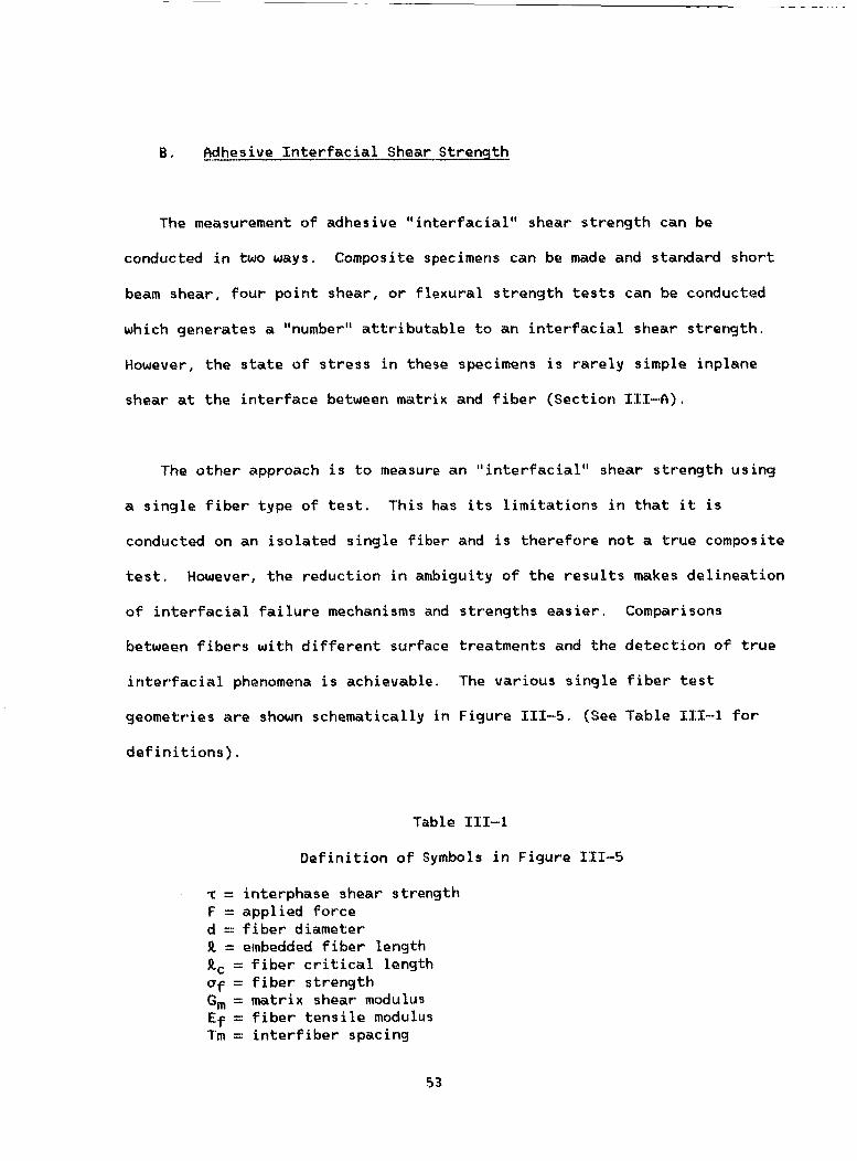
8. Cdhesive Inte-rfacial Shear Strength
The measurement of adhesive "interfacial" shear strength can be
conducted in two ways. Composite specimens can be made and standard short
beam shear, four point shear, or flexural strength tests can be conducted
which generates a "number" attributable to an interfacial shear strength.
However, the state of stress in these specimens is rarely simple inplane
shear at the interface between matrix and fiber (Section 111-0).
'The other approach is to measure an "interfacial" shear strength using
a single fiber type of test. This has its limitations in that it is
conducted on an isolated single fiber and is therefore not a true composite
test. However, the reduction in ambiguity of the results makes delineation
of interfacial failure mechanisms and strengths easier. Comparisons
between fibers with different surface treatments and the detection of true
interfacial phenomena is achievable. The various single fiber test
geometries are shown schematically in Figure 111-5. (See Table 111-1 for
definitions).
Table 111-1
Definition of Symbols in Figure 1111-5
T = interphase shear strength F = applied force d = fiber diameter R = ernbedded fiber length Rc = fiber critical length af = fiber strength Gm = matrix shear modulus Ef = fiber tensile modulus Tm = interfiber spacing
53

Single f l b e r methods f o r measuring i n t e r f a c i a l shear s t rength
I. Pull-out method
11. Microbond method
F F r = - = - A n d t
F
111. Embedded i n t e r f a c i a l shear method (37) - - - - - - - - - __t
U f d T=2n,
IV. Microdebond
Figure 111-5 Schematics of s ing le f i b e r methods of measuring i n t e r f a c i a l shear s t rengths .
54

The o l d e s t s i n g l e f i b e r t e s t i s that o f t h e f i b e r p u l l - o u t (38)
(F igu re 111-5). I n t h i s experiment a specimen i s f a b r i c a t e d i n which a
s i n g l e f i b e r i s o r i e n t e d th rough a th in d i s c o f t h e polymer o f i n t e r e s t .
The d i s c i s th in enough so that the f i l a m e n t can be p u l l e d o u t o f t h e
specimen w i t h o u t b reak ing . The fo rce r e q u i r e d t o i n i t i a l l y de tach t h e
f i b e r f r o m t h e d i s c m a t e r i a l and the f r i c t i o n a l f o r c e r e q u i r e d t o s l i d e t h e
f i b e r o u t o f t h e m a t r i x a r e recorded. Exper iments a r e conducted where t h e
embedded l e n g t h i s inc reased up t o t h e p o i n t o f f i b e r f r a c t u r e and t h e
measured fo rce f o r debonding i s p l o t t e d versus embedded l e n g t h . The s lope
o f t h i s l i n e i s t aken as t h e shear debonding s t r e n g t h .
P r a c t i c a l l y , assumptions o f a u n i f o r m shear s t r e s s d i s t r i b u t i o n a l o n g
t h e f i b e r embedded l e n g t h a r e assumed. S c a t t e r i n t h e data i s q u i t e high.
The shape o f t h e polymer meniscus a t t h e p o i n t where t h e t h e f i b e r comes
o u t o f t h e d i s c causes undes i rab le s t r e s s c o n c e n t r a t i o n f a c t o r s that
c o n t r i b u t e t o high s c a t t e r . The s t a t e o f s t r e s s under these p u l l - o u t
l o a d i n g c o n d i t i o n s c rea tes a normal t e n s i l e s t r e s s wh ich a c t s t o p u l l t h e
m a t r i x away from t h e f i b e r a t t h e e x i t p o i n t .
i s observed i n a composite.
T h i s i s t h e o p p o s i t e o f what
CI v a r i a t i o n o f t h i s technique has r e c e n t l y been developed i n wh ich a
d r o p l e t o f polymer i s formed on the f i b e r i n s t e a d o f t h e f i b e r pass ing
th rough a suppor ted d i s c (F igu re 111-5). The d r o p l e t i s cured i n a
c o n v e n t i o n a l manner and t h e f i b e r i s p u l l e d o u t o f t h e d r o p l e t as before.
55

The major d i f f e r e n c e i s that t h e s m a l l d r o p l e t c o n t r a c t s due t o s u r f a c e
t e n s i o n e f f e c t s i n t o an e l l i p s o i d a l shape h a v i n g a smooth c u r v i n g boundary
where the f i b e r e x i t s f r o m t h e d r o p . T h i s reduces but does not e l i m i n a t e
t h e s t ress c o n c e n t r a t i o n f a c t o r and t h e v a r i a b i l i t y i n t h e data observed
w i t h t h i s technique decreases (39)
Some r e s u l t s have been p u b l i s h e d u s i n g t h e p u l l - o u t t echn ique w i t h
carbon f i b e r s . The l i m i t e d number o f such r e s u l t s a r e i n some par t due t o
t h e d i f f i c u l t y i n handling s m a l l b r i t t l e f i l a m e n t s t e n microns o r l e s s i n
d iameter . Publ ished r e s u l t s f o r carbon f i b e r s i n epoxy m a t r i c e s show a
dependence o f t h e i n t e r f a c i a l shear s t r e n g t h on f i b e r t r e a t m e n t
cond it ions (40,411
c1 second approach t o t h e measurement o f i n t e r f a c i a l shear s t r e n g t h i s
t h rough t h e use o f a t o t a l l y embedded f i b e r . Fldvantage i s t a k e n o f t h e
mismatch i n s t r a i n - t o - f a i l u r e o f t h e b r i t t l e f i b e r and a d u c t i l e r e s i n . Fl
t e n s i l e specimen i s f a b r i c a t e d i n wh ich a s i n g l e f i b e r i s o r i e n t e d a x i a l l y
w i th in the t e s t coupon (F igu re 111-5). Under t e n s i l e l o a d i n g , shear f o r c e s
a r e t r a n s f e r r e d f rom m a t r i x t o f i b e r a t t h e i n t e r f a c e . The t r a n s f e r causes
t h e bui ld-up o f t e n s i l e f o r c e s i n t h e f i b e r u n t i l t h e l o c a l t e n s i l e
s t r e n g t h o f t h e f i b e r i s exceeded. The f i b e r f r a c t u r e s w i t h i n t h e polymer
coupon. T h i s process i s repeated u n t i l t h e f ragments rema in ing a r e no
l o n g e r l a r g e enough t o suppor t s u f f i c i e n t shear ing f o r c e s t o exceed t h e
f i b e r t e n s i l e s t r e n g t h . C l t t h i s p o i n t t h e f ragment l e n g t h s rema in ing
r e p r e s e n t t h e c r i t i c a l t r a n s f e r l e n g t h f o r r e i n f o r c e m e n t . f? s imp le f o r c e
56

balance r e l a t e s t h i s l eng th , t h e f i b e r p e r i m e t e r and t h e f i b e r t e n s i l e
s t r e n g t h a t t h i s c r i t i c a l l e n g t h t o an i n t e r f a c i a l shear s t r e n g t h .
The advantage of t h i s method o f measurement i s that t h e upper l i m i t t o
i n t e r f a c i a l shear s t r e n g t h i s t h e m a t r i x shear s t r e n g t h , t h e s t a t e o f
s t r e s s more c l o s e l y resembles what i s encountered i n an a c t u a l composite,
and t h e a c t u a l f i b e r - m a t r i x i n t e r f a c e can be observed w i t h p o l a r i z e d
t r a n s m i t t e d l i g h t . The f i b e r t e n s i l e s t r e n g t h can be measured
independent ly a s a f u n c t i o n o f l eng th o r su r face t rea tmen t .
f ragment l e n g t h and d iamete r a r e measured in -s i tu f o r t r a n s p a r e n t polymers
and can be determined by d i s s o l u t i o n and f i l t e r i n g o r combustion o f t h e
m a t r i x f o r t r a n s l u c e n t o r opaque m a t e r i a l s . The r e s u l t i n g parameter, t h e
i n t e r f a c i a l shear s t reng th , s t i l l i s based on t h e assumption o f a u n i f o r m
s t r e s s d i s t r i b u t i o n i n t h e f i b e r f ragments.
The f i b e r
Var ious au tho rs have pub l ished i n t e r f a c i a l shear s t r e n g t h measurements
w i t h carbon f i b e r s and epoxy ma t r i ces .
on s i m i l a r f i b e r s i n s i m i l a r mat r i ces agree q u i t e w e l l .
The va lues ob ta ined (Table 111-1)
57

F i b e r
AU
flS
tiMU
HMS
AU 1
AS 1
AU 4
AS4
AS6
IM6
C6000
C6000
T300
Tab le 111-1
F i b e r - M a t r i x I n t e r f a c i a l Shear S t r e n g t h
zP!Ec!
24
74
14
20
46
77
35
70
60
64
68
45
89
Method
Embedded S i n g l e F i b e r
Embedded S i n g l e F i b e r
Embedded S i n g l e F i b e r
Embedded S i n g l e F i b e r
Embedded S i n g l e F i b e r
Embedded S i n g l e F i b e r
Embedded S i n g l e F i b e r
Embedded S i n g l e F i b e r
Embedded S i n g l e F i b e r
Embedded S i n g l e F i b e r
Embedded s i n g l e F i b e r
M i c r o Debond
M i c r o Debond
Reference
37
37
37
37
30
30
30
30
30
30
41
42
42
A t h i r d t y p e o f t e s t r e c e n t l y proposed i s a h y b r i d between s i n g l e f i b e r
t e s t i n g and composite t e s t i n g ( F i g u r e 111-5). A p o l i s h e d c r o s s s e c t i o n o f
a c t u a l composite i s prepared and p laced under a s p e c i a l l y c o n s t r u c t e d
microscope. A s p h e r i c a l i n d e n t e r of abou t t h e same s i z e as t h e f i b e r i s
p o s i t i o n e d o v e r a f i b e r end and loaded u n t i l a f o r c e o f detachment between
f i b e r and m a t r i x i s d e t e c t e d w i t h an i n t e g r a l t r a n s d u c e r . The load i s
58

input f o r a micromechanica l model w h i c h i s t h e n used t o c a l c u l a t e an
i n t e r f a c i a l shear s t r e n g t h . 'The advantage o f t h e method i s that i t i s
a p p l i e d t o an a c t u a l composite specimen. The d isadvantage i s that a
thorough unders tand ing o f t h e events o c c u r r i n g a t t h e p o i n t o f debonding i s
n o t a v a i l a b l e . The l o a d measured has not been shown t o be a t t r i b u t a b l e
e n t i r e l y t o t h e debonding process ( 4 2 ) .
C. f t thes ive T e n s i l e S t r e n q t h
The i n t e r f a c i a l shear s t r e n g t h i s o b v i o u s l y an impor tan t s t r e n g t h
parameter o f any f i b e r - m a t r i x combinat ion. O the r l o a d i n g d i r e c t i o n s can
a r i s e wh ich do not depend on t h e f i b e r - m a t r i x shear s t r e n g t h however.
example, under t ransve rse load ing , i t i s t h e f i b e r - m a t r i x i n t e r p h a s e
t e n s i l e s t r e n g t h normal t o t h e f i b e r s u r f a c e wh ich is i m p o r t a n t .
f i b e r method f o r measuring that component o f t h e i n t e r f a c i a l s t r e n g t h i s
a v a i l a b l e .
Fo r
A s i n g l e
A compression specimen o f polymer w i t h a s i n g l e f i b e r l o c a t e d c e n t r a l l y
t h rough t h e a x i s o f t h e specimen i s f a b r i c a t e d and loaded i n compression
( F i g u r e 111-6).
compressive l oad on t h e specimen and makes use o f t h e Po isson 's e f f e c t t o
concen t ra te a normal t e n s i l e f o r c e pe rpend icu la r t o t h e f i b e r a x i s i n t h e
c e n t e r of t h e specimen. Us ing r e f l e c t e d l i g h t i t i s p o s s i b l e t o d e t e c t t h e
l o a d a t wh ich t h e m a t r i x debonds from t h e f i b e r . T h i s va lue can be used t o
c a l c u l a t e an i n t e r f a c i a l t e n s i l e s t reng th .
The hour-glass shape o f t h e sample maintains a s t a b l e
59

P r a c t i c a l l y t h i s method had been used p r i m a r i l y w i t h g l a s s f i b e r s .
f i t tempts t o use i t w i t h carbon f i b e r s have been unsuccess fu l because of t h e
compressive f r a c t u r e o f t h e f i b e r p reced ing t h e a c t u a l p o i n t o f i n t e r f a c i a l
s e para t i o n a
D. Polymer P r o p z t i e s Near t h e I n t e r f a c e
I t i s u n l i k e l y that t h e p r o p e r t i e s o f t h e m a t r i x polymer i n t h e
i n te rphase r e g i o n a r e i d e n t i c a l t o t h e b u l k polymer p r o p e r t i e s . There a r e
a number of p o s s i b l e po l ymer - f i be r i n t e r a c t i o n s ; s e l e c t i v e a d s o r p t i o n of
m a t r i x components, c o n f o r m a t i o n a l e f f e c t s , p e n e t r a t i o n o f polymer molecules
i n t o t h e f i b e r sur face, d i f f u s i o n and i n t e r a c t i o n o f low MW components from
t h e f i b e r , and c a t a l y t i c e f f e c t s o f t h e f i b e r s u r f a c e on polymer network
f o r m a t i on .
60

where m, € = matrix, f i b e r V = Poisson's ratio U axial stress a t mlnimum cross-sectlon E Young's modulus
Figure 111-6 fin interfacial adhesion tensile test configuration ( 4 6 )
6 1

V a r i a t i o n s i n m a t r i x p r o p e r t i e s nea r t h e carbon f i b e r s u r f a c e can be
i n f e r r e d f r o m i n d i r e c t exper iments. Spec t roscop ic p r o b i n g would r e q u i r e
s p a t i a l r e s o l u t i o n o f one-tenth o f a m ic ron o r l e s s . Such a probe i s n o t
a v a i l a b l e .
The t y p e o f substrate-polymer i n t e r a c t i o n that can occu r i s i l l u s t r a t e d
by a study o f t h e bonding o f epoxy m a t r i c e s cured w i t h an amine c u r i n g
agen t t o a copper su r face (43 ) . T h i s work documented t h e d i f f u s i o n and
chemiso rp t i on o f t h e amine f rom t h e b u l k polymer t o t h e copper s u r f a c e .
Because o f t h e concur ren t d i f f u s i o n and r e a c t i o n o f t h e amine, an amine
d e f i c i e n t l a y e r o f l e s s than a hundred nanometers i n t h i c k n e s s was c r e a t e d
between t h e s u r f a c e enhanced and b u l k r e g i o n s
A s i m i l a r o b s e r v a t i o n was made i n work d i r e c t e d a t understanding t h e
r o l e o f a r e s i n r i c h f i n i s h on carbon f i b e r - m a t r i x adhesion (44),
amine d e f i c i e n t l a y e r was c rea ted around t h e f i b e r , m a t r i x f r a c t u r e
r e s u l t e d under t h e same l o a d i n g c o n d i t i o n s that had p r e v i o u s l y g i v e n r i s e
t o i n t e r f a c i a l f r a c t u r e . The p r o p e r t i e s o f t h i s amine d e f i c i e n t l a y e r were
shown t o be more b r i t t l e than t h e b u l k m a t r i x h a v i n g t h e s t o i c h i o m e t r i c
amount o f c u r i n g agen t .
When an
Other m a t r i x p r o p e r t i e s a f f e c t i n g t h e i n t e r f a c i a l adhesion have been
documented i n t h e l i t e r a t u r e . S e m i c r y s t a l l i n e t h e r m o p l a s t i c m a t r i c e s have
been shown t o n u c l e a t e and c r y s t a l l i z e on t h e s u r f a c e o f carbon f i b e r s i n a
62

manner d i f f e r e n t f rom t h e b u l k polymer. The su r face c r y s t a l l i z a t i o n has
been hypothes ized a s b e i n g respons ib le f o r improvements i n adhes ion
p r o p e r t i e s between f i b e r and m a t r i x . (45 1
The commercial s i z i n g agents a p p l i e d t o carbon f i b e r t o reduce f i b e r
damage during p rocess ing (Sec t i on 11-8) undoubtedly a f f e c t t h e i n te rphase
compos i t i on r e l a t i v e t o t h e b u l k m a t r i x . However, t h e r e has not been any
c l e a r ev idence that these s i z i n g s a f f e c t composite mechanica l p r o p e r t i e s
p o s s i b l y because they a r e u s u a l l y fo rmula ted t o be chemica l l y s i m i l a r t o
t h e m a t r i x r e s i n so that any i n t e r d i f f u s i o n o f s i z i n g and m a t r i x does n o t
produce a s t r o n g g r a d i e n t i n p r o p e r t i e s th rough t h e i n te rphase r e g i o n .
FI number o f research s t u d i e s have been r e p o r t e d on f i b e r s i z i n g s o r
(46-48 c o a t i n g s " t a i l o r e d " t o improve composite p r o p e r t i e s . Subramanian
has r e p o r t e d e x t e n s i v e l y on e lec t ro -depos i ted c o a t i n g s and p u b l i c a t i o n s by
McMahon, Ying and Maximovich ( 5 0 9 5 1 ) compare v a r i o u s s i z i n g s against a
commercial epoxy-based s i z i n g . For t h e m o s t part t h e e f f e c t s o f t h e
d i f f e r e n t s i z i n g s were r e l a t i v e l y s m a l l and f r e q u e n t l y i n v o l v e d a t r a d e - o f f
i n p r o p e r t i e s , e .g . , an inc rease i n impact s t r e n g t h but a decrease i n
t e n s i l e and/or shear p r o p e r t i e s .
FI s p e c i a l t y p e o f s i z i n g i s t h e " i n n e r l a y e r " that i s a p p l i e d t o c r e a t e
a g r a d i e n t i n mechanica l p r o p e r t i e s between f i b e r and m a t r i x . The
t h e o r e t i c a l mechanics o f a low modulus i n n e r l a y e r have been developed by
63

Savin(52) and by A r r i d g e ( 5 3 ) .
develop l o w modulus i n n e r l a y e r s but w i t h mixed e f f e c t s o n composi te
p r o p e r t i e s . Some o f t h e e l e c t r o d e p o s i t e d c o a t i n g s developed by Sabramanian
were designed t o be low modulus i n n e r l a y e r s . Kardos, Cheng and
To 1 b e r t (54) showed that t h e development o f a c r y s t a l l i n e l a y e r a t t h e
CF/polycarbonate i n t e r f a c e s i g n i f i c a n t l y improved composi te p r o p e r t i e s .
W i l l i a m s and Kousiounelos (55) d e s c r i b e a system o f a thermoplast ic ’
c o a t i n g w i t h t h e r m o p l a s t i c m i c r o f i b e r s i n a CF/epoxy composi te. Some o f
t h e i r data a r e shown i n Tab le 111-2. F o r t h r e e d i f f e r e n t l a m i n a t e
c o n f i g u r a t i o n s they show an improvement i n both t e n s i l e s t r e n g t h (except
f o r COO]) and notched f r a c t u r e s t r e s s , K .
Numerous a t tempts have been made t o
4
Recent ly, McGarry, e t a l . (56) have extended t h e i r i n v e s t i g a t i o n s o f
e las tomer i c a d d i t i v e s f o r c r o s s l i n k e d g l a s s y polymers (epoxys, p o l y e s t e r s )
t o t h e use o f t hese e lastomers as th in (50-70nm) c o a t i n g s on carbon f i b e r
re in fo rcemen t ,
64

Laminate
C o n f i q u r a t i o n
T e n s i l e S t r e n g t h and F r a c t u r e Toughness (K ) q
Table 111-2
Compos i t e Po ly s u l f o n e
Proper tL - Coatinq __
452
1 3 . 9
540
1 7 . 2
587
2 7 . 1
No Coa t inq
3 75
8 . 5
396
8 . 7
664
6 . 8
2 * unnotched t e n s i l e s t reng th , MN/m , normal ized t o cons tan t f i b e r
volume f r a c t u r e
3 /2 ,#*notched f r a c t u r e s t r e s s i n t e n s i t y , MN/m
E. I n t e r f a c i a l Process inq Cond i t ions
The process ing o f po l ymer i c composites brings t h e polymer i n t o i n t i m a t e
c o n t a c t w i t h t h e f i b e r su r face .
v i s c o s i t y f l u i d s i n t h e mol ten s ta te , p rocess ing v a r i a b l e s , such as t ime,
tempera ture and pressure become very i m p o r t a n t f o r insuring i n t i m a t e
c o n t a c t . Carbon f i b e r su r face chemical compos i t ion , thermodynamic
p r o p e r t i e s such a s f i b e r su r face f r e e energy and polymer su r face f r e e
65
Because most polymers a r e r e l a t i v e l y high

energy, sur face t o p o g r a p h i c a l f ea tu res , and o t h e r su r face and i n t e r f a c i a l
p r o p e r t i e s a r e p o t e n t i a l l y use less i n e i t h e r p romot ing o r p r e d i c t i n g
f i b e r - m a t r i x adhesion i f t r u e e q u i l i b r i u m i n t i m a t e mo lecu la r c o n t a c t i s n o t
achieved a t t h e i n t e r f a c e .
Th is has i m p l i c a t i o n s f o r va r ious processes wh ich t a k e p l a c e during t h e
fo rma t ion o f t h e f i b e r - m a t r i x i n t e r p h a s e . The f i r s t process t o occu r i s
t h e w e t t i n g o f t h e carbon f i b e r by t h e mo l ten polymer. The macroscopic
parameter c h a r a c t e r i s t i c o f t h i s process i s t h e v i s c o s i t y . Temperature
increases can be used t o reduce t h e v i s c o s i t y t o a m i n i m u m va lue f o r a
g i v e n polymer. Pressure and t i m e can be used t o extend t h e c o n t a c t t i m e
and promote i n t e r a c t i o n a t t h e mo lecu la r l e v e l .
F l f te r i n t i m a t e c o n t a c t has been ach ieved t h e su r face and i n t e r f a c i a l
f o r c e s a c t i n g i n t h e r e g i o n can a l t e r t h e l o c a l compos i t ion . I n polymers
o f i d e n t i c a l compos i t ion f o r example, o l i gomers o f d i f f e r e n t mo lecu la r
w e i g h t can e x i s t wh ich a l t h o u g h c h e m i c a l l y i d e n t i c a l can have d i f f e r e n t
s u r f a c e f r e e energ ies . Under su r face f r e e energy d r i v i n g forces, l o n g e r
mo lecu la r we igh t components would be p r e f e r e n t i a l l y adsorbed a t t h e
i n t e r f a c e .
would depend on t h e s e l f - d i f f u s i o n p r o p e r t i e s o f t h e polymer cha ins . R
process ing t i m e o f very s h o r t d u r a t i o n would n o t a l l o w t h i s e q u i l i b r i u m
c o n d i t i o n t o be achieved.
promote a seg rega t ion by mo lecu la r we igh t that may be d e s i r a b l e o r
undes i rab le depending on how i t a f f e c t s i n t e r p h a s e p r o p e r t i e s .
The t ime r e q u i r e d f o r t h i s e q u i l i b r a t i o n by mo lecu la r w e i g h t
On t h e o t h e r hand, a long p rocess ing t i m e may
66

The same type of segregation can occur by differential adsorption. In
thermoset systems preferential adsorption may drive one component to the
fiber surface. The attainment of an adsorption equilibrium may never be
achieved if the time and temperature conditions are not correct. High
temperatures allow faster diffusion but increase
early formation of the crosslinking polymer network. Even under
equilibrium conditions there is no %,,priori, reason why the composition o f
the adsorbed phase should be identical to that of the bulk phase.
the reaction rate causing
The phenomena of epitaxial crystallization has been shown to occur with
carbon fibers in semicrystalline thermoplastics. Here again there is a
nucleation step which is the precursor to crystallization. Crystallite
growth then exhibits a time and temperature dependency which varies with
the polymer structure.
Finally as has been shown earlier, significant quantities of
potentially volatile materials desorb from the fiber surface under
temperatures encountered during composite processing. The removal of these
volatile materials is important to achieving molecular contact. If the
volatiles are not removed with the application of vacuum before
consolidation, they may create voids at the fiber-matrix interface. The
only possible mechanism for removal after consolidation of the matrix is by
dissolution into the matrix and diffusion away from the fiber-matrix
interface. While the amount of materials volatilized is potentially very
67

s m a l l (one monolayer e q u i v a l e n t ) , t h e l o c a l c o n c e n t r a t i o n of desorbed
m a t e r i a l (water , carbon monoxide and carbon d i o x i d e ) can be q u i t e high
T h i s s i t u a t i o n w i l l be aggravated if t h e desorbed m a t e r i a l i s p o o r l y
s o l u b l e i n t h e surrounding m a t r i x po lymer,
F . F i b e r / M a t r i x Adhesion and Composite Mechanical- P r o p e r t i e s
T e n s i l e (Oo) S t r e n q t h The p r imary f u n c t i o n o f t h e m a t r i x r e s i n i n a
f i b e r r e i n f o r c e d composi te i s t o t r a n s f e r s t r e s s between f i l a m e n t s . I n
exper iments w i t h s i n g l e f i l a m e n t s embedded i n r e s i n i t i s a r e l a t i v e l y
s imp le m a t t e r t o show that t h e l e v e l o f s t r e s s t r a n s f e r i n t o t h e f i l a m e n t
i s d i r e c t l y r e l a t e d t o t h e s t r e n g t h o f t h e bond between m a t r i x and f i b e r
(see Sec t ion I I L - B ) . I n a f i b e r tow o r l a m i n a t e t h e s i t u a t i o n i s more
complex. I f a f i b e r breaks, t h e m a t r i x t r a n s l a t e s t h e l o a d t o t h e
ne ighbor ing f i b e r s . However, a t t h e b roken f i b e r ends t h e r e i s r e g i o n o f
s t r e s s c o n c e n t r a t i o n and u n l e s s d i s s i p a t e d may induce f a i l u r e i n a d j a c e n t
f i b e r s and p r e c i p i t a t e c a t a s t r o p i c f a i l u r e o f t h e tow o r l a m i n a t e .
A c t u a l l y , t h e r e i s a high shear s t r e s s c o n c e n t r a t i o n a t t h e t i p o f a broken
f i l a m e n t which can cause i n t e r p h a s e debonding and r e l i e v e l o c a l s t r e s s
concen t ra t i ons . A l though t h e d e t a i l s a r e obscure and s u b j e c t t o debate,
t h e r e i s g e n e r a l agreement that some l o c a l c l u s t e r o f f i b e r breaks
( c r i t i c a l c l u s t e r ) must deve lop i n o r d e r f o r t h e tow o r l a m i n a t e t o
f r a c t u r e .
a c r i t i c a l c l u s t e r and a l a r g e body of l i t e r a t u r e has developed around t h i s
concept
Bo th t h e o r y (57 y 5 8 ) and exper iment (59) suppor t t h e concept o f
68

I n t h e c o n t e x t o f t h i s r e p o r t , i t would appear that f o r m a x i m u m t e n s i l e
s t r e n g t h t h e bond between f i b e r and r e s i n must be s u f f i c i e n t t o a l l o w
s t r e s s t r a n s f e r f r o m r e s i n t o f i b e r b u t s u f f i c i e n t l y weak t o f a i l i n shear
t o r e l i e v e s t r e s s c o n c e n t r a t i o n s i n t h e v i c i n i t y o f a f i b e r b reak .
Transverse (goo) S t r e n q t h I n the t r a n s v e r s e d i r e c t i o n , t h e f i b e r - r e s i n
i n t e r f a c e i s sub jec ted t o t e n s i l e s t resses . F i n i t e element a n a l y s i s
i n d i c a t e s s t r e s s m a g n i f i c a t i o n a t the i n t e r f a c e (60) and i t has been
suggested that f i b e r debonding i s the p robab le cause o f t r a n s v e r s e crack
i n i t i a t i o n .
i n OO/900/Oo l am ina tes and p resen t evidence that c rack p ropaga t ion i s c l o s e
t o t h e f i b e r r e s i n boundary.
B a i l e y and co-workers (61) have s t u d i e d t r a n s v e r s e c r a c k i n g
I n r e c e n t work Adams, e t . a l . (62) used a f i n i t e element method (FEM)
a n a l y s i s t o c h a r a c t e r i z e t h e micromechanics o f t r a n s v e r s e f a i l u r e . fin
example o f t h e r e s u l t s o f t h i s a n a l y s i s i s g i v e n i n F i g u r e 111-7 which
shows one quadrant f o r a carbon f i b e r i n a high modulus epoxy m a t r i x .
that t h e a n a l y s i s p r e d i c t s m a t r i x y i e l d i n g i n t h e r e g i o n a l o n g t h e 00
d i r e c t i o n and that subsequent f r a c t u r e leads to m a t r i x c r a c k i n g and
apparen t i n t e r f a c i a l f a i l u r e . T h i s s tudy i n c l u d e d v a r i o u s m a t r i x r e s i n s ,
t h e e f f e c t of the rma l s t resses and adsorbed m o i s t u r e on t r a n s v e r s e
s t r e n g t h .
e x p e r i m e n t a l t e s t r e s u l t s when a maximum normal s t r e s s f a i l u r e c r i t e r i a was
used. A t e l e v a t e d temperatures and m o i s t u r e a d s o r p t i o n l e v e l s , t h e
Note
There was good agreement between p r e d i c t e d f a i l u r e l o a d and
69

a) No Mechanical Loading
c) a' = 25 MPa (3 .6 k s i ) x
Figure 111-7 Transverse t e n s i l e loading: 3501/cIS-4 unid i rect ional composite, 25OC, <. 40% RH. Shaded areas, m a t r i x ye i ld ing , dark areas m a t r i x f racture (62 1
70

a n a l y s i s i s " co r rec ted" f o r some assumed pe rcen t deg rada t ion o f t h e
i n t e r f a c i a l bond r e l a t i v e t o t h e " p e r f e c t bond" developed a t 25OC. T h i s
combined use o f FEM a n a l y s i s and exper imenta l t e s t data i s very p o w e r f u l i n
t h e a n a l y s i s and p r e d i c t i o n of f a i l u r e micromechanics. However, i t shou ld
be p o i n t e d o u t that a FEM p r e d i c t i o n o f i n t e r f a c i a l f a i l u r e i s l i m i t e d t o
t h e s i z e o f t h e s m a l l e s t g r i d element a t t h e f i b e r r e s i n boundary and t h a t
t h i s element m u s t o f n e c e s s i t y be l a r g e compared t o mo lecu la r d imensions.
Thus, t h e i n t e r f a c i a l f a i l u r e p r e d i c t e d i n F i g u r e 111-7 i s near t h e f i b e r
r e s i n i n t e r f a c e but w i th in some r e l a t i v e l y macroscopic s i z e e lement .
Indeed, i n t h e model used by Rdams, a d e g r a d a t i o n i n bond s t r e n g t h i s
i n t r o d u c e d a s a degrada t ion i n t h e m a t r i x p r o p e r t i e s o f t h e element a t t h e
f i b e r r e s i n boundary. T h i s work i s b e i n g extended t o reduce t h e
i n t e r f a c i a l g r i d s i z e and i n t r o d u c e r e l e v e n t i n te rphase p r o p e r t i e s .
-I--."...- Shear S t r e n g t h Laminate shear t e s t s have been r o u t i n e l y used t o
e v a l u a t e f i b e r m a t r i x bond s t r e n g t h . I t i s g e n e r a l l y assumed that a
c o n d i t i o n o f in-p lane shear e x i s t s and that f a i l u r e occurs by m a t r i x shear
y i e l d i n g , debonding o r some combinat ion o f b o t h . Indeed t h e r e a r e a t l e a s t
two ins tances where low i n t e r f a c i a l s t r e n g t h has been determined
independent ly (by s i n g l e f i b e r t e s t s (37)) and t h e cor respond ing l am ina te
shear s t r e n g t h found t o be low.
- vs RS4 i n Tab le 111-1) and t h e other i s high modulus f i b e r (HMS i n Tab le
IIX-1) where t h e sur face of t h e f i b e r i t s e l f i s cohes ive l y weak. F i g u r e
11-8 g i v e s an example o f t h e e f f e c t o f su r face t rea tmen t on 4-po in t shear
s t r e n g t h ,
One case i s unsur face t r e a t e d f i b e r (RU4
The shear s t r e n g t h f o r f i b e r w i t h o u t su r face t rea tmen t was
7 1

significantly low but increased to a plateau level within less than the
normal surface treatment level and maintained this plateau level up to
surface treatments 120% greater than normal. In this instance the fiber
was given various levels of electrolysis treatment both above and below the
condition normally used in production. The matrix resin was a
tetrafunctional/amine cured epoxy. It was not possible to find treatment
levels that gave shear strength intermediate between no treatment and the
plateau level. Other studies of surface treatment variations have also
found it difficult to find a set of conditions that give intermediate shear
strengths. It would appear that the shear tests are nut sensitive enough
to detect small differences in fiber surface conditions.
Unfortunately, there is a widely held belief that shear tests,
especially the short beam shear (SBS, ASTM D2344) test, provide an
unambiguous measure o f fiber resin bond strength. As already mentioned
shear failure involves matrix shear yielding, debonding or some combination
of the two. Moreover, the bonding may include cohesive (shear) failure of
the fiber surface itself. The possibility of matrix yielding is especially
likely in laminates manufactured by prepreg layup which usually result in a
distinct resin layer between plys.
strength test results invariably means low interfacial strength has led to
some heroic (and expensive) efforts to increase the chemical functionality
on the fiber surface on the assumption that this would improve laminate
shear properties,
The misconception that low shear
72

The t y p e o f shear t e s t s can a l s o be a f a c t o r . The SBS t e s t specimen,
f o r example, can f a i l by modes o t h e r than in -p lane shear, e .g . , t e n s i l e o r
compressive f r a c t u r e , and c r u s h i n g under t h e loading b a r s . The s u b j e c t o f
shear t e s t i n g has been thorough ly documented i n t h e l i t e r a t u r e (63,64 1
SgmAression ( O O ) S t r e n q t h Laminate f a i l u r e under u n i d i r e c t i o n a l (00)
compressive loads i s n o t w e l l understood and, i n f a c t , has been t h e s u b j e c t
o f cons ide rab le s tudy i n r e c e n t years . The c u r r e n t t heo ry i s that
compressive s t r e n g t h i s determined by l am ina te b u c k l i n g s t a b i l i t y .
C o r r e l a t i o n s have been found between t h e compressive s t r e n g t h and m a t r i x
modulus--the s t i f f e r t h e m a t r i x t h e b e t t e r t h e f i b e r suppor t . R t a more
m ic roscop ic l e v e l , r e c e n t ev idence has been presented that f o r o r g a n i c
f i b e r s (Kev la r , PBT) t h e micro-buck l ing i s determined by t h e
(66) m i c r o - s t r u c t u r e of t h e f i b e r
(65 1
To t h e e x t e n t that in te rphase s t r e n g t h i nh ib i t s f i b e r m i c r o b u c k l i n g o r
f i b e r bund le k i n k i n g , one might expect t o observe some e f f e c t on
compressive s t r e n g t h . T h i s p o s s i b l i t y i s i m p l i c i t i n t h e a n a l y s i s by Hahn
and W i l l i a m s (65).
(10%) e f f e c t of carbon sur face a l t e r a t i o n on compression s t r e n g t h .
However, C u r t i s and Mar ton (67) found o n l y a s m a l l
I V CRIT’ICRL. ISSUES
Our p r e s e n t s t a t e o f knowledge on o r g a n i c m a t r i x carbon f i b e r
composites a s o u t l i n e d i n t h e preceding s e c t i o n s i s severe ly inadequate as
73

a base f o r p r e d i c t i n g t h e e f f e c t o f t h e i n t e r f a c e on composi te p r o p e r t i e s .
There i s o n l y f ragmentary i n f o r m a t i o n about t h e mechanica l p r o p e r t i e s o f
t h e sur face o f CF o r about CF/matr ix i n te rphases . Chemical i n f o r m a t i o n i s
e q u a l l y l i m i t e d about t h e CF s u r f a c e a s i t i s produced, a f t e r su r face
t rea tmen t and i n t h e CF/matr ix i n t e r p h a s e . The s i t u a t i o n i s made worse by
t h e f a c t that most o f what i s known i s based on ve rs ions o f carbon f i b e r
that a r e no l onger produced o r , if i n p roduc t i on , t h e manu fac tu r ing
c o n d i t i o n s have been s i g n i f i c a n t l y a l t e r e d t o i nc rease p r o d u c t i o n r a t e s .
I n some ins tances t h e r e have been s i g n i f i c a n t changes i n t h e PAN
p recu rso r . There i s e s s e n t i a l l y no i n f o r m a t i o n i n t h e open l i t e r a t u r e o n
t h e newer f o r m s o f CF such as t h e i n t e r m e d i a t e modulus f i b e r s .
1; the n e x t few s e c t i o n s ques t i ons a r e posed that need t o be answered
i n o r d e r t o b e t t e r c h a r a c t e r i z e CF sur faces , CF/matr ix i n t e r p h a s e r e g i o n s
and t h e e f f e c t o f t h e i n te rphase on mechanica l p r o p e r t i e s .
R . P r o p e r t i e s o f CF Sur faces
1. The "as formed" s u r f a c e o f CF i s a p o o r l y d e f i n e d carbonaceous
l a y e r t h a t i s p a r t l y a romat i c and p a r t l y a l i p h a t i c w i t h adsorbed m a t e r i a l
( i n c l u d i n g l o w MW o r g a n i c m a t e r i a l s ) and h i g h l y r e a c t i v e s i t e s (unpa i red
e l e c t r o n s , f r e e r a d i c a l s , i o n i c spec ie ) . I t i s p robab ly c o h e s i v e l y weak.
T h i s sur face begins t o e q u i l i b r a t e w i t h t h e ambient env i ronment a s soon a s
t h e f i b e r emerges f r o m t h e carbonization/graphitization f u rnaces .
Commercial su r face t rea tmen t processes a l t e r t h i s s u r f a c e l a y e r by removing
74

" loose" m a t e r i a l and changing i t s chemical compos i t i on .
understand t h e i n t e r f a c i a l p r o p e r t i e s o f CF composites i t i s necessary t o
c h a r a c t e r i z e t h i s t r e a t e d sur face. The f o l l o w i n g a r e some o f t h e e s s e n t i a l
ques t i ons that need t o be answered.
I n o r d e r t o
a. How much o f t h e su r face t rea tment process i s a mechanica l c l e a n i n g
o f l oose m a t e r i a l and how much i s chemica l a l t e r a t i o n ?
b. f i re t h e r e s i g n i f i c a n t d i f f e r e n c e s i n t h e e f f e c t o f d i f f e r e n t
commercial su r face t reatments. ?
c . What a r e t h e mechanica l p r o p e r t i e s o f t h e t r e a t e d su r face and how
do they va ry w i t h depth?
d . I s t h e su r face l a y e r porous and what i s t h e s c a l e o f t h e p o r o s i t y ?
e . What i s t h e chemical c o n s t i t u t i o n o f t h e t r e a t e d su r face and how
does t h e chemis t ry vary w i t h depth?
f . What i s t h e degree o f sur face h e t e r o g e n e i t y b o t h i n topography and
chemica l c o n s t i t u t i o n ? What i s t h e s c a l e o f t h e he te rogene i t y?
75

2. There are a variety of techniques that can be used to determine
the chemical and mechanical properties of CF surfaces.
a , Wettability measurements; Sensitive to outer surface molecular
constitution (surface specific), provide information on surface
heterogeneity and surface energetics.
Experimentally difficult, data analysis in terms of surface
chemical composition can be ambiguous.
b. Surface spectroscopics (Auqer, XPS, SIMS); Provide information on
atomic and molecular constituents, techniques vary in surface
specificity, can be used for depth profile measurements, limited
to testing in high vacuum. Examination of single fibers would
require development of special equipment.
c. Thermal desorption; Useful for characterizing physically and
chemically adsorbed specie, and surface decomposition at
processing temperatures.
d . fhdsorption analysis; Provide information on surface morphology
(porosity) and, using chemically specific adsorbents, on chemical
composition. The low specific area of CF requires very sensitive
analytical detectors.
76

3 . There a r e c r i t i c a l ques t i ons abou t t h e mechanical p r o p e r t i e s o f CF
s u r f a c e s .
a. What a r e t h e modulus and s t r e n g t h o f t h e s u r f a c e l a y e r ? How
do they d i f f e r i n shear, t e n s i o n and compression?
b. How do t h e mechanica l p r o p e r t i e s vary i n d e p t h and a l o n g t h e
l e n g t h of t h e f i b e r ?
c . Are t h e mechanica l p r o p e r t i e s d i f f e r e n t f o r d i f f e r e n t s u r f a c e
t reatments, do they change w i t h t i m e a f t e r s u r f a c e t rea tmen t?
d . What r e l a t i o n s h i p i s t he re between t h e mechanica l p r o p e r t i e s
o f t h e s u r f a c e l a y e r and t h e s u r f a c e f l a w s that i n i t i a t e
? f i b e r breakage.
4 . The t o o l s a v a i l a b l e t o determine CF' s u r f a c e mechanica l p r o p e r t i e s
a r e r e l a t i v e l y l i m i t e d .
a. Contact f r i c t i o n : Rdhesion s t r e n g t h and s t a t i c and dynamic
f r i c t i o n between c o n t a c t i n g f i l a m e n t s can, i n p r i n c i p l e , g i v e
d i r e c t i n f o r m a t i o n about s u r f a c e mechanica l p r o p e r t i e s . The
technique i s very d i f f i c u l t and r e p o r t e d o n l y once i n t h e
open l i t e r a t u r e (39). Nonetheless, i t m e r i t s f u r t h e r
i n v e s t i g a t i o n .
77

b. Sur face D i f f r a c t i o n : Some i n f o r m a t i o n about mechanical
p r o p e r t i e s cou ld be d e r i v e d from su r face s p e c i f i c X-ray,
e l e c t i o n o r neu t ron d i f f r a c t i o n . I n many ins tances low a n g l e
s c a t t e r i n g techniques would need t o be r e f i n e d o r developed.
8 . Prp_pert ies o f t h e Matt-&,
The m o l e c u l a r p r o p e r t i e s o f t h e m a t r i x polymer u l t i m a t e l y i n f l u e n c e t h e
in te rphase r e g i o n . Measurement o f these p r o p e r t i e s a r e r e l a t i v e l y straight
forward a l t h o u g h i t cannot be assumed these b u l k p r o p e r t i e s a r e unchanged
when the polymer con tac ts t h e f i b e r . Some o f t h e e s s e n t i a l i n f o r m a t i o n
needed are ;
1. V i s c o s i t y ( i n c l u d i n g t ime/ tempera ture dependence).
2 . Sur face tens ion , e s p e c i a l l y o f m o l t e n t h e r m o p l a s t i c s .
3 . Chemical compos i t ion i n c l u d i n g r e a c t i v e groups, m o l e c u l a r we igh t
and we igh t d i s t r i b u t i o n , i m p u r i t i e s , m o l e c u l a r s i z e .
4 . Q d s o r p t i o n behav io r on CF su r faces i n c l u d i n g b o t h chemical and
p h y s i c a l adso rp t i on , and a d s o r p t i o n conformat ion ( f rom s o l u t i o n
and m e l t ) .
78

C. P r g e r t i e s o f t h e I n t e r p h a L t
1. The p r o p e r t i e s o f t h e in terphase r e g i o n , both mechanical and
chemical , a r e c r i t i c a l t o composi te performance. U n f o r t u n a t e l y , t hese
p r o p e r t i e s a r e d i f f i c u l t t o measure d i r e c t l y and t h e i n t e r p r e t a t i o n o f
i n d i r e c t measurements a r e o f t e n ambiguous. Some o f t h e e s s e n t i a l q u e s t i o n s
that need study a re ;
a . What a r e t h e mechanical p r o p e r t i e s o f t h e i n t e r p h a s e reg ion?
How do these p r o p e r t i e s va ry normal t o t h e CF/matr ix boundary
and a l o n g t h e f i b e r ?
b.
C .
d .
e .
Given t h e mechanica l p r o p e r t i e s f o r t h e i n te rphase , a r e
e x i s t i n g a n a l y t i c a l models adequate t o p r e d i c t t h e e f f e c t o f
t h e i n t e r p h a s e on composite p r o p e r t i e s ?
Is t h e r e p e n e t r a t i o n o f matr ix molecules i n t o t h e carbon
f i b e r s u r f a c e l a y e r ? What i s t h e d e p t h o f p e n e t r a t i o n ?
Does t h e f i b e r sur face i n f l u e n c e t h e m a t r i x polymer s t r u c t u r e
by d i f f e r e n t i a l adsorpt ion, polymer c o n f o r m a t i o n a l e f f e c t s
and/or e f f e c t i n g t h e c ross - l i nked network s t r u c t u r e ?
How do s i z i n g s a f f e c t t h e i n te rphase? How can s i z i n g
c o a t i n g s be t a i l o r e d t o enhance composi te p r o p e r t i e s .
79

f . What are the effects of residual stresses on the properties
and structure of the interphase?
g . Can CF surfaces nucleate crystallization of matrix polymers,
what are the nucleation sites? What are the conditions
(thermal history, etc. ) for crystall.ization?.
h . What are the conditions for flaw initiation and growth in the
interphase region. ?
2. Some of the methods of studying the interphase region are;
a. Single fiber shear adhesion tests; The interphase shear
strength can be measured by embedded fiber or fiber pull-out
(and push-out) tests. If the organic matrix is transparent
and photoelastic, the stress birefringence patterns provide
useful information.
b. Transmission electron microscopy; Cross-sectioning can be
used to identify the locus o f failure and some
microstructural properties of the interphase.
80

c. Depth profilinq; The interphase region can be analyzed by
SIMS or other surface spectroscopy techniques but the
experimental conditions must be carefully designed and will
require high resolution beam instruments.
d. Laminate testinq; Testing of composite specimens in
combination with closed-form or FEM analyses oFfer
considerable potential for discerning the properties o f the
interphase and its effect on composite properties.
CONCLUSIONS
The overall conclusion of this review is that our state-of--knowledge
concerning the adhesion of carbon fibers to organic matrix polymers is
unacceptably poor. Two major consequences of this fact are:
1. The adhesion of carbon fiber to thermoplastic polymers is very low
so it is doubtful that the full mechanical properties and
environmental stability of these composites are being realized.
2. Without some quantitative knowledge of the mechanical (and
chemical) properties of the carbon fiber/matrix interphase, it is
difficult to realistically model composite mechanical behavior.
81

Clearly, research is needed to characterize carbon fiber surfaces,
their interfacial interactions with organic polymers and the properties o f
the interphase. This research must be:
I 1. Interdisciplinary - surface chemistry and physics, mechanical
testing and modelling.
2. Exploration of unconventional experimental and analytical
approaches,
3. Funded on a short term basis to "fix" the thermoplastic problem
and on a long term, high risk, basis to address difficult
questions and explore unconventional investigative techniques.
82

APPENDIX I
Attendees a t t h e workshop on C r i t i c a l I s s u e s on Carbon F i b e r adhesion, NASa Langley Research Center, Hampton VA, Dec 10-12, 1985.
P r o f . Don Adams Dept . O f Mechanica l Eng ineer ing U n i v e r s i t y o f Wyoming Box 3295 U n i v e r s i t y S t a t i o n Laramie, WY 82071
O r . Wi l lard Bascom Hercu les Aerospace D i v . Bacchu s Works Magna, UT 84044
D r . John Crews NASI9/LaRC M a i l S t o p 188E Hampton, VA 23665-5225
D r . Jane Crosby, Manager Produc t Development D i v i s i o n LNP C o r p o r a t i o n 412 King S t r e e t Ma lvern , PCI 19355
Tad D e V i l b i s s Virginia Tech Chemist ry Dept . B lacksburg, VCI 24061
D r . Ron Deh l N a t i o n a l Bureau o f Standards B l d g 224, Rm. I9209 Ga i thersburg , MD 20899
P r o f e s s o r Lawrence D r z a l M ich igan S t a t e U n i v e r s i t y Dept . o f Chemical Eng ineer ing E a s t Lansing, M I 48824-1226
D r . J e f f r e y H ink l e y NASA/L.aRC M a i l S t o p 226 Hampton, V I I 23665-5225
83

D r . Paul Hergenro ther NASFI/L.aRC M a i l Stop 226 Hampton, VFI 23665-5225
M r . Ken Hummel Hercules heros pace Bacchu s Works Magna, U T 84044
D r . Norman Johns t o n D r . Paul Hergenro ther NFISfVLaRC M a i l Stop 226 Hampton, VFI 23665-5225
D r . Robert Lande l J e t P ropu ls ion Labora to ry C a l i f o r n i a I n s t i t u t e o f Technology M a i l Code 67-201 4800 Oak Grove D r i v e Pasadena, Ch 91109
P r o f . John Mande 11 School o f Eng ineer ing Massachusetts I n s t i t u t e o f Technology Cambridge, MFI 02139
D r . Bernard M i l l e r T e x t i l e Research I n s t i t u t e P.O. Box 625 Pr ince ton , N J 08542
D r . Lynn Penn M i d w e s t Research I n s t i t u t e 425 Vo lker B l v d . Kansas C i t y , MO 64110
D r , R. E . Robertson Dept o f M a t e r i a l s S c i . & Eng. H.H. Don B l d g The U n i v e r s i t y o f M ich igan FInn Orbor, M I 48109-2135
P r o f . George M. Whi tes ides Department o f Chemistry Harvard U n i v e r s i t y 12 O x f o r d S t r e e t Cambridge, MFI 02138
84

Dr. Edwina Ying Celanese Research Company 86 Morris Rvenue Summit, NJ 07901
Dr. Lincoln Ying M&T Chemicals, Inc. P . O . Box 1104 Rahway, NJ 07065
85

REFERENCES
1 . Johnston, N J.: "Synthesis and Toughness Properties of Resins and Composites', > Corllposite Matmals and
NASA CP-2321, August 1984.
2. Coleman, M.M.; and Siuy, 6.1.: "Fourier Transfor I R Studies o f the Degradatlon of Polyacrylonltrlle Copolymers-I," Carbon 1p 123 (1981 1
3. Goodhew, P. J.: " A Reuieur o f the Fabrication and Properties o f Carbon Fibres,' Mat. Sci. Eng., 3 (1975)
4. Bennett,S.C.; and Johnson,DJ.: proc. Fifth London C a m d Grg Dnite J;PDferenc&Uoi I, SOC. Chem. Ind., London, 1978, p.377
5 Watts, W.; and Johnson, 0. J,: proc. m d C p n l on 1- Graohite. SOC. Chem. Ind., London, 1971, p.417
6. Perret, R.;and Ruland, W.: "The Microstructure of PAN-Base Carbon Fibres", J. Appl. Cryst. 3 525 (1970)
7. Johnson, 01.: Carbon Fibers 9 Their Cornos ition and Q R I U U U Q , The Plastics Institute, 1971, p.57
8. Peters, P.W.M.; and Springer, 6. S.: "Effect of Cure and Sizing on Fiber -MatriH Bond Strength,", ACWAL- TR - 86- 4054, Sept 84-Sept 86, Wright- Patterson, AFB, , OH.
9. Hopfgarten, F.: 'Surface studies o f Carbon Fiber with Auger Electron Spectroscopy' Biennial Conf. on Carbonu 288 (1977)
10. Slegbahn, K.; Nordberg,G. 'ESCA Applied to Free Molecules," North- Holland Press, Amsterdam, 1969
11. Drzal, 1.1.: 'The Surface Composition and Energetics of Type A Graphite Fibers,' Carbon, 129 (1977).
1 2. Dnal, 1.1.; Meschner,J.A.;and Hall,D.L.: "The Surface Composition and Energetics of Type HM Graphite Fibers,': Carbon 11 375 (1979).
13. Bendure, R.L.: "Dynamic Adhesion Tension Measurements," J. Colloid and Interface Sci., 92 137 (1 973).
1 4.Adamson, A.W.: of Solids, Wiley. N.V., 1976, p344.
15. Ellison, A.H.; f OH, H.W.;and Zitman, W.cI.: "Wetting of Fluorinated Solids by Hydrogen-Bonding Liquids," J. Phys. Cham. Z 622 (1953).
8 6

16. Ulu, S.,mymsr Interfocs and Fldhea ions Dekksr, NY 1982.
17. Fourkes,F.M; and Mostafa, J.A.: " Acid-Base interactions in Polymer Adsorption," 1nd.t) Eng.Chem., Prod.Res.and Deu., u 3 (1978)
18. Ehrburger,P.;and 0onnetJ.B.: " interface in Composite Materials," Phil. Trans. R. SOC. Lond. 495 (1980)
19. Donnet, J.B.; and Bansal, R m C a : m o n F W , Dekker, NY 1984.
20. Denison,P.; Jones, F.R.; and Ulatts, J.F.: "X-ray Photoelectron Spectroscopic Analysis of Barium-Labelled Carbon Fibre Surfaces," J. Mat. Scl. 2p 4647 (1985).
21. Drzai, 1.1.; Rich,M J.; Camping,D J.; and Park, Ul J.: " Interfacial Shear Strength and Failure Mechanisms in Graphite Fiber Composites," 35th Proc. Reinforced Plastics and Composites Conference, SOC. Plastics ind., 1980, p.20-6.
22. Diefendorf,R J.; and Tokarsky,E.: "High Performance Carbon Fibers," Polym. Eng. Sci. fi 150 (1975).
23 Badami, D.U.; Joiner, J.C.; and Jones, 6.A.: "Microstructure of High Strength, High Modulus Carbon Fibres," Nature -386 (1967).
24. Chen,K J.; and Dlefendorf, R J.: etngress in Science and h9jneeriOg pf Corllpositet T. Hayashi, Ed.;, ICCS-IU, Tokyo, 1982.
25. Bascom, W.D.; and Boll, D J a : "Crltical Properties Control o f Carbon Fiber Reinforcements," Final Report, Air Force Contract AFUlClL-TR-82- 4165, A i r Force Rept., No. H400-12-1-0?5, December 1982, Hercules Aerospace, Magna Ut.
26. Donnet, J.B.: "Structure and Reactiuity o f Carbons : From Carbon Black to Carbon Composites," Carbon 2p 267 (1982).
27. Boehm, H.P.; Diehl, E.; Heck ID.; and Sappock, R.:"Surface Oxides o f Carbon" Agneur. Chem., ;T 669 (1964).
28. Hopfgarten, F.: "Surface Study o f Carbon Fibres with ESCA and Auger Electron Spectroscopy," Flber Sci. Tech., u 6 7 (1978).
29. Hammer, 6.E.; and Dnal, 1.1.: "Graphite Fiber Surface Analysis by X- Ray Photoelectron Spectroscopy and Polar/Dispersion Free Energy Anal~sis," Appl. SUrfa S C l a , 9 350 (1980).
a7

30. Rich, MJ.; and Orzal, L.T.: "Interfacial Properties of Some High-Strain Carbon Fibers in an EPOHY MatriH," 4lst Ann. Conf. Reinforced Plastics/Composites Inst., SOC. Plastics. ind., January 1986, p. 2F.
31. Ishitanl, A.: "Application of H-ray Photoelectron Spectroscopy to Structure AnalpiS of Carbon Fiber," Carbon 1p 269 (1981).
32. Beitel, 6. A. : "The Use of Graphite in High and Ultrahigh Uacuum ; A Reuiew," Uac. Scl. Tech. 647 (1971).
33. Kaeible, D.H.,mysical Chemistr y a f Adhesiok Wiley-interscience, NY, 1971.
34. BascomJJ.0.; Gadomski, S.T.; Henderson, C.M.; and Jones, R.L.: "Fracture Markings on Stress-Corroded EpoHy/AlUminUm Butt Joints," J. Adhesion 8 21 3 (1977).
35. Ahagon, A; and Gent, A.N.: "Effect o f interfacial Bonding on the Strength of Adhesion," J. Polym. Sci. 1285 (i975).
36. Roselman, I.C.; and Tabor, 0.: "The Friction of Carbon Fibres," J. Phys. 0: Appl. Phys. p 2517 (1976).
37. Drzal, 1. T.; Rich, M.J.; and Lloyd, P.F.: "Adhesion o f Graphite Fibers to EPOHY Matrices: I. The Role of Fiber Surface Treatment," J. Adhesion @ I (1983).
38. Broutman, 11.: "Measurement of the Fiber-Polymer MatriH Interfacial Stmngth," -in%, ASTM STP 327, Amer. SOC. for Tertlng Meterlals, Philadelphia, PR. 1963, p.133.
39. Miller, E.; Muri, P.; and Rebenfeld,L.: " A Microbond Method for Detemination of the Shear Strength of a Fiber/Resin Interface," Comp. Sci. and Technol. 28 17 (1986).
40. Penn, 1.; Bystry, F.; Karp, UJ.; and lee, S.: "AramidlEpoxy us Graphite/Epoxy; Origin of the Difference in Strength at the Interface," plolecular Chwteri;L9tion of Cpmgrrsite Interfaces, H. lshida dnd 6. Kumar, Eds., Plenum Pub. 1985, p.93.
41. Ving,L: "Effects of Fiber/Matrix Interactions on the Properties of Graphite/Lpo~y Composites," 38th Ann. Tech. Conf., Reinforced Plastics/Comporltes, SOC. Plastics Ind., 1980, p 20C.

42. Mandell, J.F.; Grande, D.N.; Tsiang, T.H.; and McGarry, F.J.: "Modified Mlcrodebonding les t for Direct lnsitu Fiber/MatriH Bond Strength Determinations in Fiber Composites," FISTM STP 893, B s t and W W , ~ Qmf, I 3. Whitnsy, Ed. , tlmsr Soc for Teating Hat. , Philadelphia, PCI, 1996, p. 87.
43. Racich, J.L.; and Koutsky, J.A.: "Boundary layers in Thermosets," Cnemistrumd PrQDerties of Cross - Linked P o w e r s , S. Labona, Ed., Academic Press 1977 p. 303.
'44. Drzal, 1.1.; Rich, M.J.; Lloyd, P.F.; and Koenig, M.F.:*Adhesion of Graphite Fibers to EPOHY Matrices: II The Effect of Fiber Finish," J. Adhesion, fi 133 (1983).
45. Hobbs, S.Y.: "Row Nucleation o f Isotactic Polypropylene on Graphite Fibres," Nature 12 (1971 1.
46. Subramanian, R. U,; and Jakubowksi, J.J.: "Electropolymerization on Graphite Fibers," Polym. Eng. Sci., fi 590 (1978).
47. Subramanian, R.U.; Jakubowski, J J.; " Interphase Resin Modifications in Graphite Composites," RCS Symp. Series, h i n s for f l erosw€&, uz 257 (1980).
48. Subramanian, R.U.; Jakubowski, J.J.; and Williams, R.D.: " Interfacial Aspects o f Polymer Coatings by Electropolymerization," J. Adhesion 9 185 (1978).
49. Deleted.
50. McMahon, P.E.; and Ying, 1.: "Effects of Fiber/MatriH Interactions on the Properties of Graphite/EpoHy Composites," NASA CR-3607, Sept 1982.
51. McMahon, P.E.; and MaHimouich, M.: flduances in Corngosite Materials, A.R. Bunsell, C.Bathias, A. Martrenehar, 0.Menices and 6. Uerchory, Eds., Uol2, ICCM 3, Proc. 3rd Inter. Conf. on Composite Materials, Paris, Sept. 1980 Pergamon Press.
52 Sauin, 6.N.: Stress C-on ArPlunefiPlae Pergamon Press, London, 1961,p.234.
53. Arrldge, R.G.C.: "The Effect of Interlayers on the Transuerse Stresses in Fiber Composites," Polym. Eng. 0 Sci., 15 757 (1975).
89

54. Kardos, d.1. ; Cheng, F.S.; and Tolbert, T.L.: "Teyloring the Interface in Graphite-Rslnlorced Polycarbonate," Polym Eng.D Sci. 13 455 (1973).
55. Williams, J.H.; and Kousiounelos, P.N., 'Thermoplastic Fibre Coatings Enhance Composite Strength and Toughness,' Fiber Sci. and Tech. u 8 3 (1978).
56. McGarry, FJ.; Mandell, J.F.: and Kawamoto,J.: "Rubber in Crosslinked Glassy Polymers, " Rduanced Composites Conf., Proc. Amer. Sot. Metals, Dec 1985.
57. Phoenix, S. 1.; and KUO, C.C.:"Recent Rduances in Statistical and Micromechanical Modeling of the Time Dependent Failure of Fibrous
Yuccogin, R.L.Sicrakourski, D.% Glasgour, Eds., Rmer. Soc. Mech. Engs., NY 1983.
Composites," fldu.in AeroSpace S tflctures, Mate rials ana DY-9
58. Mandert, P.W.; Bader, M.C.; and Chou T-UI.: 'Monte Carlo Simulation of the Strength of Composite Fiber Bundles," Fiber Sci. and Tech., 17 183 (1982).
59. Jamison, R.D.: 'The Role of Microdamage in Tensile Failure of Graphite/EpoHy Laminates,' Comp. Sci. and Tech., 24 83 (1985).
60. Chamis, C.C.: m- Uol 5,L.J.Jroutman and R.H. Krock, Eds., 1974.
61. Bailey, J.E.; Curtis, PJ.; and Porulzi, R.:"On the Transuerse Cracking and Longitudinal Sglit'ting of Carbon Fiber Reinforced Epoxy Cross-Ply Laminates and tbe Effect of Poisson and Thermally Generated Strain," Proc. R. Soc London, n366 599 (1979).
62. Zimmerman, R.S.; and Rdams, 0. F.: 'Mechanical Properties Testing of Candidate ,Polymer Matrix Materials for Use in High Performance Composites,' NASA CR-177970, Dec 1985.
63, Chlao, C.C. ; Moore, R.L.; and Chiao, T.T.: "Measurement o f Shear Properties of fiber Composites. Part I, Eualuation of Test Methods," Composites B(July) 16 1 (1977) . 64. Ulhitney, J. M.; and Husman, 6.E.: "Use o f the FleHUre Test for Determining Enuironmental Rehauior o f Fibrous Composites,"EHp, Mech, 18 185 (1978).

I i I I
65. Hahn, H.T.; and Ulllllams, 3.6.: 'Con3g8site failure Mechasnisms in Unidirectional composite^,^ tWW TM-85834, nug 1984.
66. DeTeresa, SJ.; Portef, R.S.; (M9 PanJs, Rd.: " A Model for the Compressiue Buckling ef fatended Chain Polymers,' J. Mat. Sei., 2Q 1645 (1985).
67. Curtis, P. T.; and Harton, J.: P r n a r e J E c e -gl(reerjngqf m m ICCM-IU, Tokyo, 1982.
91

Standard Bibliographic Page
1. Report No.
NASA CR-4084 2. Government Accession No.
7. Author(s) W . D . Bascom and L . T . Drzal
17. Key Words (Suggested by Authors(s))
Carbon fibers F i ber/matri x adhesi on Organic matrix composites
9. Performing Organization Name and Address
Hercules Aerospace Magna, UT 84044
18. Distribution Statement
Unclassified - Unlimited
Subject Category 24
12. Sponsoring Agency Name and Address
National z4eronautics and Space Adminis t ra t ion Washington, DC 20546-0001
Langley Technical Monitor: J. A. Hink1e.y 15. Supplementary Notes
19. Security Classif.(of this report) Uncl assi fied
3. Recipient’s Catalog No.
20. Security Classif.(of.this page) 21. No. of Pages 22. Price Unclassified 96 A0 5
5 . Report Date
July 1987 6. Performing Organization Code
8. Performing Organization Report No.
10. Work Unit No.
505-66-41-04 11. Contract or Grant No.
NAS1-17918 13. Type of Report and Period Covered
Contractor Report 14. Sponsoring Agency Code
- - W. D. Bascom:
L . T. Drzal: Michigan State University, East Lansing, Michigan 48823
Hercules Aerospace, Magna, Utah (presently a t University of Utah, Materials Science and Engineering Department, S a l t Lake City, Utah 84112)
16. Abstract
The s t a t e of knowledge of the surface properties of carbon f ibers i s reviewed, with emphasis on fiber/matrix adhesion i n carbon f ibe r reinforced plast ics . Subjects treated include carbon f ibe r structure and chemistry, techniques for the study of the f iber surface, polymerlfiber bond strength and i t s measurement, variations in polymer properties i n the interphase, and the influence of f iber matr ix adhesion on composite mechanical properties. Crit ical issues are summarized and research recommendations are made.
For sale by the National Technical Information Service, Springfield, Virginia 22161 NASA-Langley , 1987