Embed Size (px)
Citation preview
Load Transfer Analysis in Short Carbon Fibers with Radially-Aligned Carbon Nanotubes Embedded in a Polymer Matrix
The MIT Faculty has made this article openly available. Please share how this access benefits you. Your story matters.
Citation Ray, M.C., Roberto Guzman de Villoria and brian L. Wardle. "LoadTransfer Analysis in Short Carbon Fibers with Radially-AlignedCarbon Nanotubes Embedded in a Polymer Matrix." Journal ofAdvanced Materials, issue 4, (Jan. 2009).
As Published http://www.sampe.org/news/jam/2009/2009jamissue4.aspx
Publisher Society for the Advancement of Material and Process Engineering
Version Author's final manuscript
Citable link http://hdl.handle.net/1721.1/71852
Terms of Use Creative Commons Attribution-Noncommercial-Share Alike 3.0
Detailed Terms http://creativecommons.org/licenses/by-nc-sa/3.0/
Load Transfer Analysis in Short Carbon Fibers with Radially-Aligned Carbon
Nanotubes Embedded in a Polymer Matrix
M. C. Ray
Department of Mechanical Engineering, Indian Institute of Technology, Kharagpur
721302, India
Roberto Guzman de Villoria and Brian L. Wardle
Department of Aeronautics and Astronautics, Massachusetts Institute of Technology,
Cambridge, MA 02139, USA
A novel shortfiber composite in which the microscopic advanced fiber reinforcements
are coated with radially aligned carbon nanotubes (CNTs) is analyzed in this study. A
shear-lag model is developed to analyze the load transferred to such coated fibers from
the aligned-CNT reinforced matrix in a hybrid composite application. It is found that if
the carbon fibers are coated with radially aligned CNTs, then the axial load transferred
to the fiber is reduced due to stiffening of the matrix by the CNTs. Importantly, it is
shown that at low loading of CNTs in the polymer matrix, there is a significant reduction
in the maximum interfacial shear stress, e.g., at 1% CNTs, there is an ~25 % reduction
in this maximum stress. Further, the modification in the load sharing between the fiber
and the matrix plateaus at ~2% CNT matrix loading, indicating a small but critical
window for engineering the interface in this manner. Effects of the variation of the
aspect ratio of the fiber, CNT volume fraction and the application of radial load on the
load transferred to such CNT coated fibers are also investigated.
KEYWORDS: Nanocomposites, Composite Structures

2
1. Introduction
The identification of carbon nanotubes1 (CNTs) has stimulated extensive
research devoted to the prediction of their elastic properties through experiments and
theoretical modeling. Of interest is to determine elastic properties of the CNTs as an
input to models that predict composite behaviour. Early work by Treacy et al.2
experimentally determined that CNTs have Young’s modulus in the terapascal (TPa)
range. Li and Chou3 linked structural and molecular mechanics (MM) approaches to
compute elastic properties of CNTs. Sears and Batra4 used three MM potentials to
simulate axial and torsional deformations of a CNT assuming that the tube can be
regarded as a hollow cylinder of mean diameter equal to that of the CNT and
determined the wall thickness, Young’s modulus and Poisson’s ratio of the CNT. Shen
and Li5 assumed that a CNT should be modeled as a transversely isotropic material
with the axis of transverse isotropy coincident with the centroidal axis of the tube. They
determined values of the five elastic constants by using a MM potential and an energy
equivalence principle. Batra and Sears6 proposed that the axis of transverse isotropy of
a CNT is a radial line rather than the centroidal axis of the tube and found that Young’s
modulus in the radial direction equals about 1/4th of that in the axial direction. Wu et al.7
developed an atomistic based finite deformation shell theory for single-walled CNT and
found its stiffness in tension, bending and torsion.
A great deal of research has also been carried out on the prediction of effective
elastic properties of CNT-reinforced composites. For example, Thostensen and Chou8
have estimated the elastic moduli of CNT-reinforced composite through
micromechanical analysis. Gao and Li9 derived a shear lag model of CNT reinforced
3
polymer composites by replacing the CNT with an equivalent solid fiber. Song and
Yoon10 numerically estimated the effective elastic properties of CNT-reinforced polymer
based composites. Siedel and Lagoudas11 carried out a micromechanical analysis to
estimate the effective properties of CNT-reinforced composites. Guzman de Villoria and
Miravete devolped a model to estimate the effect of the CNTs dispersion in composites
matrix by micromechanical analysis12. Jiang et al.13 derived a continuum based model
to study the effect of CNT/matrix interface on the macroscopic properties of CNT-
reinforced composites. Odegard et al.14, 15 have modeled CNT-reinforced composite to
estimate effective elastic moduli using an equivalent-continumm modeling method that
connects computational chemistry and solid mechanics models. To avoid the long times
of simulation of materials at nanoscale level, Yamakov and Glaessgen16 have linked
continuum mechanics in with atomic-level simulations, in one case to study the fracture
tip of several metals. Zhang and He17 theoretically investigated the viscoelastic behavior
of CNT-reinforced composites developing a three-phase shear-lag model. Most
recently, Ray and Batra18 carried out a micromechanical analysis to estimate the
effective elastic and piezoelectric properties of CNT and piezoelectric fiber reinforced
hybrid composite. Several review articles have appeared that summarize the various
advances in these two-phase (CNTs plus a matrix) nanocomposites19-21.
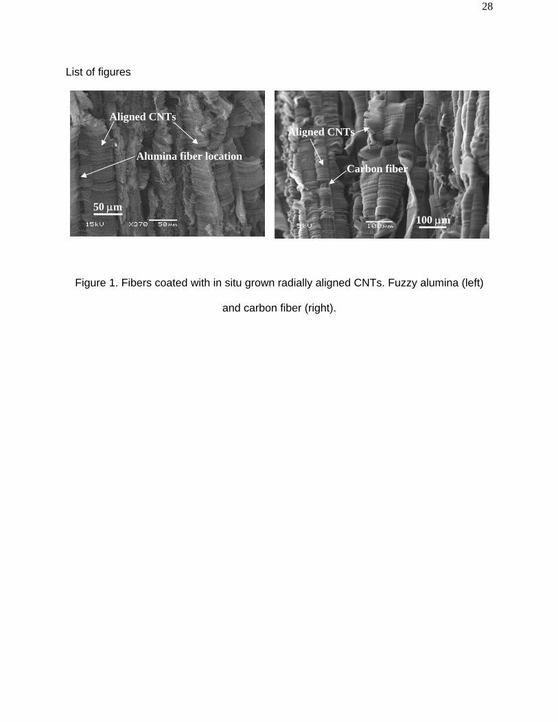
Here we analyze a new hybrid composite composed of micron-scale diameter
advanced fibers with in situ grown radially aligned CNTs and a polymer matrix. Growth
of aligned CNTs on advanced fibers (see examples in Figure 1) have been investigated
by several groups22-26 and recently, bulk composites have been realized using aligned
‘fuzzy’ fibers27-29. The objective of this work is to investigate the load transferred to a

4
carbon fiber from the matrix in the case where the micon-scale fuzzy fiber is
discontinuous (see Figure 2). A closed-form shear lag model is developed for such
investigation, incorporating a micromechanics model for predicting the radially-
orthotropic properties of the aligned-CNT reinforced polymer matrix. Such composites
can be described as a hybrid nano-engineered composite, where the polymer matrix is
reinforced with radially aligned-CNT resulting in an aligned-CNT nanocomposite matrix
that surrounds the micron-scale advanced fiber (see Figure 3). Such nano-engineered
composites can be fabricated using capillarity-driven wetting of the aligned CNTs by
advanced polymers29, 30.
2. Shear lag model
A schematic sketch of the cylindrical representative volume element (RVE) of the
composite analyzed here is shown in Figure 3. The cylindrical coordinate system ( , r θ
and ) is considered in such a way that the axis of the RVE coincides with the axis
while the CNTs are aligned along the -direction. The model is derived by dividing the
RVE into three zones. The portion of the RVE in the zone
x x
r
ff LxL ≤≤− consists of a
discontinuous micro-scale advanced fiber (carbon is considered here) reinforcement on
which radially aligned CNTs have been grown. When this resulting fuzzy fiber is
embedded in a polymer material, the CNT forest is filled with the polymer creating a
nano-reinforced polymer matrix, what many have called a polymer nanocomposite
(PNC) 31, 32. Thus, the radially aligned CNTs reinforce the polymer matrix and the
portion of the RVE in the zone ff LL x ≤≤− can be viewed as a hybrid composite
comprised of the carbon fiber reinforcement embedded in the CNT-reinforced polymer

5
matrix composite phase. The radius and the length of the carbon fiber are denoted by
and , respectively. The inner and outer radii of the CNT-reinforced matrix phase
are and
a fL2
a R , respectively. The portions of the RVE in the zones fLxL −≤≤− and
are treated in the model as an imaginary fiber and the matrix phase, both
composed of the polymer material. The radius of the imaginary fiber is also denoted by
while the inner and outer radii of the matrix phase are also represented by a and
L≤x≤Lf
a R ,
respectively. Thus, the shear lag model developed for the zone ff LxL ≤≤− can be
applied to derive the shear lag models for the zones fLxL −≤≤− and . LxLf ≤≤
ff xL L≤≤−In what follows, the shear lag model for the zone is first derived. A
tensile stress is applied to the RVE along x direction at 0σ Lx ±= while the RVE is
subjected to a radial normal stress at 0q Rr = . In order to derive this shear lag model,
the effective properties of the aligned CNT-reinforced matrix phase are needed. This
PNC matrix phase has transverse isotropy in a radial coordinate system due to the CNT
alignment and isotropic nature of the polymer. This is a slight approximation because
the grown CNTs have reduced volume fraction as they grow radially, but volume
fraction may be considered constant over the small (microns) CNT lengths considered.
Micromechanics is used to calculate properties in this region as they have not been
determined experimentally to date. A micromechanics model by Ray and Batra18 is used
to calculate the effective elastic constants for a forest of aligned single-walled CNTs
(properties from Ref.5 given in Table 1) embedded in a polymer (results summarized in
Table 2). These results are used as an input to the shear-lag model.
Returning to the shear-lag model, the governing equations for the different
6
phases of this RVE concerning equilibrium along direction are given by x
01=
∂σ∂
+∂σ∂
r)r(
rx
ixr
ix , fi = and
(1)
m
while the relevant constitutive relations are
and ; ir
iiiix
iix CCC ∈+∈+∈=σ θ 131211
ixr
iixr C ∈=σ 55 fi = and
(2)
m
In Eqs. (3) and (4), superscripts and denote, respectively, the carbon fiber and the
CNT-reinforced PNC matrix. For the i -th constituent phase, and represent the
normal stresses in the and r , directions, respectively; , and are the normal
strains along , and , directions, respectively; is the transverse shear stress,
is the transverse shear strain and are the elastic constants . It should be noted
here that the principal material coordinates 1, 2, 3 axes are also considered to be
coincident with the problem coordinate axes ,
f m
iijC
ixσ
iθ∈
irσ
ir∈x
r
ix∈
x θ ixrσ
ixr∈
x θ , , respectively. Hence, the
conventional subscripts are used to write the elastic constants appearing in Eq. (2). The
strain-displacement relations for an axisymmetric problem relevant to this RVE are
r
xui
ix ∂
∂=∈ ,
rw i
i =∈θ , r
wiir ∂
∂=∈ and
xw
ru ii
ixr ∂
∂+
∂∂
=∈ ; and
(3)
fi = m

7
in which and represent the axial and radial displacements at any point of the i -th
phase along x and r , directions, respectively. The traction boundary conditions are
given by
iu iw
0qRr
mr =σ
= and 0=σ
=Rrmxr
(4)
and the continuity conditions are
ar
mrar
fr ==
σ=σ , iarmxrar
fxr τ=σ=σ
==,
arm
arf uu
=== and
arm
arf ww
===
(5)
Where, is the transverse shear stress at the interface between the carbon fiber and
the PNC matrix phase The average axial stresses in the different phases are defined as
iτ
rdra
afx
fx π∫ σ
π=σ 21
02 , and rdr
)aR(
R
a
mx
mx π∫ σ
−π=σ 21
22
(6)
Now, making use of Eqs. (1) and (4) to (6), it can be derived that
i
fx
axτ−=
∂σ∂ 2 and i
mx
aRa
xτ
−=
∂σ∂
222
(7)

8
Since the radial dimension of this RVE is very small, it is reasonable to assume that the
gradient of with respect to the axial coordinate ( x ) is independent of the radial
coordinate (r ). Thus let us assume that
mxσ
)x(x
mx φ=
∂σ∂
(8)
Integrating the governing equation (1) for the PNC matrix phase from to r R , it can be
shown that
mxrrR
r)x( σ−
−=φ 222
(9)
Substituting iarmxr τ=σ
= in Eq. (9), the transverse shear stress in the PNC matrix can be
expressed in terms of the interface shear stress iτ as follows:
imxr )aR(
arr
Rτ
−⎟⎟⎠
⎞⎜⎜⎝
⎛−=σ 22
2
(10)
Also, since the RVE is an axisymmetric problem, it may further be assumed that the
gradient x
wi
∂∂ of radial displacements with respect to -direction is negligible and so,
from the constitutive relation (2) between and one can write,
x
mxrσ m
xr∈

9
mrxi
m
Cxu
σ=∂
∂
55
1
(11)
Solving Eq. (11), the axial displacement of the matrix phase along x direction can be
derived as follows:
(12)
ifa
m Auu τ+= 1
in which ar
ffa uu
== and
⎭⎬⎫
⎩⎨⎧ −−
−= )ar(
arlnR
)aR(CaA m
22222
552 2
1
(13)
The radial displacements in the two phases can be assumed as in33 :
and rAw ff =
rB
rAw mm
m +=
(14)
where , and are unknown constants. Invoking the continuity conditions for
radial displacement at the interface (
fA mA mB
ar = ) it can be found that:
mfm A)
rar(A
raw
22−+=
(15)

10
Invoking the continuity condition ar
mrar
fr ==
σ=σ and satisfying the boundary condition
0qRr
mr =σ
=, the following equations for solving and are derived : fA mA
xCA
qCC
CCAA
AAAA i
mf
fx
m
fm
m
f
∂τ∂
⎭⎬⎫
⎩⎨⎧
+⎭⎬⎫
⎩⎨⎧
−+
σ
⎭⎬⎫
⎩⎨⎧ −
=⎭⎬⎫
⎩⎨⎧
⎥⎦
⎤⎢⎣
⎡
1320
1113
1213
2221
1211 01
0
(16)
where,
mmf
fff CC
C)C(
CCA 233311
212
1211112
−+−+= , , mCA 3312 2−= f
fmmm
CCC
Ra)CC(A
11
12132
2
2333212
+−= ,
2
2
2333332322 Ra)CC(CCA mmmm −++= , RrAA
== 12 .
From Eq. (16), the solutions of and can be expressed as: fA mA
x
LqLLA ifxf ∂
τ∂++σ= 131211 and
xLqLLA if
xm ∂τ∂
++σ= 232221
(17)
The expressions of the coefficients are evident from Eq. (16) and are not shown
here for the sake of brevity. The equilibrium of force along the axial ( x ) direction yields
ijL

11
(18)
∫ πσ∫ +πσ=σπR
a
mx
afx rdrrdrR 22
00
2
Using Eqs. (6), (17) and the constitutive relations, Eq. (18) can be reduced to
fx
i
LL
qLL
LR
xσ−+
σ=
∂τ∂
3
20
3
1
3
02
(19)
where,
2221211 LBLBL −= , 21211122
11
1122 LBLB)aR(
CC
aL f
m
+−−+= , , 2321311133 LBLBCAL m +−=
∫=R
ardrAA 13 2 , ∫ ⎥
⎦
⎤⎢⎣
⎡−−=
R
a
mmf
mf
drr
a)CC(rC
CCB
2
131211
11121
22 ,
and ∫ ⎥⎦
⎤⎢⎣
⎡−−+=
R
a
mmmm drr
a)CC(r)CC(B2
131213122 2 .
Substitution of Eq. (7)1 into Eq. (19) yields the governing equation for the average axial
stress in the carbon fiber coated with radially aligned CNTs as follows:
002
2
2
qx
fx
fx μ−ησ−=σα−
∂
σ∂

12
(20)
where,
3
22 2aLL
=α , 3
22aLR
=η and 3
12aL
L=μ
(21)
Following the above procedure, the governing equation for the average axial stress
( pfxσ ) in the imaginary fiber made of the polymer material lying in the zones
and can be written as fLxL −≤≤− LxLf ≤≤
002
12
2
qx
pfx
pfx μ−ση−=σα−
∂
σ∂
(22)
In the above equation, the expressions for , 21α η and μ are similar to those of , 2α η
and , respectively. But these are to be derived by considering .
Solutions of Eqs. (21) and (22) are given by:
μ pij
mij
fij CC = C=
qecec xxfx 2221 α
μ+σ
αη
++=σ α−α
(23)
021
021
43 qecec xxpfx
α
μ+σ
α
η++=σ α−α
(24)

13
in which , , and are the constants of integrations to be evaluated from the
following end conditions:
1c 2c 3c 4c
0σ=σ pfx at Lx ±= and pf
xfx σ=σ at fLx ±=
(25)
Utilizing the end conditions given by (25) in Eqs. (23) and (24), the final solutions for
pfxσ and f
xσ are obtained as follows:
00
02
12
102
1
02
11
1 1 σ⎪⎭
⎪⎬⎫
⎪⎩
⎪⎨⎧
σα
μ+
α
η+⎟
⎟⎠
⎞⎜⎜⎝
⎛
σα
μ−
α
η−
αα
=σqq
)Lcosh()xcosh(pf
x
(26)
00
20
20
022
122
102
1
02
11
1 1 σ⎥⎥⎦
⎤
⎢⎢⎣
⎡
σα
μ+
αη
+⎪⎭
⎪⎬⎫
⎪⎩
⎪⎨⎧
σ⎟⎟⎠
⎞⎜⎜⎝
⎛
αμ
−α
μ+
αη
−α
η+⎟
⎟⎠
⎞⎜⎜⎝
⎛
σα
μ−
α
η−
αα
αα
=σqqq
)Lcosh()Lcosh(
)Lcosh()xcosh( f
f
fx
(27)
In the case that the fiber and matrix are isotropic, and with =0, the above model
reduces to that presented by Gao and Li9 for a CNT reinforced polymer composite.
Finally, substitution of Eq. (27) into Eq. (7) yields the expression for the interface shear
stress as follows:
0q
00
022
122
102
1
02
11
1 12
σ⎥⎥⎦
⎤
⎢⎢⎣
⎡
⎪⎭
⎪⎬⎫
⎪⎩
⎪⎨⎧
σ⎟⎟⎠
⎞⎜⎜⎝
⎛
αμ
−α
μ+
αη
−α
η+⎟
⎟⎠
⎞⎜⎜⎝
⎛
σα
μ−
α
η−
αα
ααα
−=τqq
)Lcosh()Lcosh(
)Lcosh()xsinh(a f
fi
(28)

14
3. Results and Discussion
The elastic coefficients of arm chair type CNTs with respect to the coordinate system
considered here are obtained from Shen and Li5 which are listed in Table 1. The
polymer material and the carbon fiber are elastically isotropic. The isotropic elastic
coefficients ( ) of the polymer materia18 and the elastic constants ( ) of the high
modulus M40 carbon fiber34 needed for computing the numerical results are as given by
pijC f
ijC
GPa.Cp 3511 = , , and . GPa.Cp 1312 = GPa.Cf 8937311 = GPa.Cf 5612 =
A discussion on the effective properties of the PNC matrix is now in order.
Recently, Ray and Batra18 derived a micromechanics model to predict the effective
properties of CNT and piezoelectric fiber reinforced hybrid composite. In the absence of
piezoelectric fibers this micromechanics model is reduced to a model which predicts the
effective elastic properties of the transversely isotropic PNC matrix with radially aligned
CNTs considered here and is given by:
(29)
142
131
−− += ]V][C[]V][C[]C[ m
The various matrices appearing in (29) are presented in the Appendix. At a particular
value of CNT volume fraction ( =1.0%), the effective values of the elastic constants
of the PNC matrix predicted from Eq. (29) are presented in Table 2 for different
types of armchair CNTs. Also, for =1.0%, the elastic constants of the PNC
CNTV
mijC
CNTV mijC
15
matrix with (10, 10) CNTs presented in Table 2 yield the values of the Young’s modulus
( ) in the radial direction and the Poisson’s ratio ( ) as 14.34 GPa and 0.369,
respectively. The values of the same are also predicted identically from simple rule of
mixtures validating the micromechanics model given by Eq. (29). Thus Eq. (29) can be
used to compute the effective elastic constants of the PNC matrix for evaluating the
numerical results.
mrE m
xrυ
mijC
For presenting the results, following nondimensional parameters are adopted:
0
fx
σσ
=*σ and 0
10σ
τ=τ i*
(31)
Unless otherwise mentioned, the values of the geometrical parameters of the RVE are
taken as:
m.a μ= 53 , maR μ+= 10 , 10=a/Lf and 21.L/ fL =
Arm chair type (10, 10) CNTs are used to compute the numerical results for the axial
stress and the interface shear stress, unless specifically varied. In order to validate the
model derived in the previous section, first the normalized average axial stress in the
fiber without coated with CNTs and the interface shear stress are compared with those
obtained by an existing model9 as shown in Figure 4. For this comparison, the fiber is
an arm chair (10, 10) CNT as considered in Ref.9. It may be noted that the good

16
agreement between the two sets of results have been obtained verifying the present
model. The marginal differences observed may be attributed to the fact that the model
in Ref.9 did not consider the radial deformation, whereas in the present model radial
deformations have been taken into account. Next, results are computed for carbon
fibers coated with radially aligned CNTs.
The variations of the axial normal stress in the short carbon fiber and the
transverse shear stress at the interface between the fiber and the PNC matrix along the
length of the fiber are shown in Figure 5. It may be observed that the carbon fiber
coated with radially aligned-CNTs shares less load than the fiber without coated with
CNTs. This is attributed simply to the radial and axial stiffening of the polymer matrix by
the CNTs. Note that the axial Young’s moduli of the PNC matrix with 1% (10, 10) CNT
and the polymer are and , respectively while the radial
Young’s moduli are and , respectively. The CNTs create
a radially orthotropic PNC matrix and an increase in the CNT volume fraction increases
both the axial and radial modulii. Importantly, the maximum interfacial shear stress is
reduced in the case of CNTs reinforcing the matrix. A critical parameter in the design of
polymer matrices for composites is the ratio of this maximum stress to the strength of
the matrix. Load sharing improves this ratio with the presence of only 1% CNTs by 23%,
and it is also expected that the strength of the interface should increase due to the
CNTs as well, further improving the effect. The axial load transferred to the carbon fiber
and the interfacial shear stress decreases with the increase in the radial stiffness of the
PNC matrix as shown in Figure 6 and Figure 7, respectively. Also, compared in Figure 6
and Figure 7is the case where the matrix remains isotropic but the value of its Young’s
GPa.Emx 413=
GPa.mr 3414=
GPa.Epx 013=
GPa.Epr 013=E

17
modulus is increased to that of of the PNC with =1.0% (Poisson’s ratio is
assumed as 0.33). It may be observed from these figures that isotropically stiffening the
matrix causes (as expected) a significant increase in load carried by the matrix and a
reduction in the interfacial maximum shear stress beyond what is seen at 1% radially-
aligned PNC.
mrE CNTV
a/R In Figure 8, it may be seen that if the value of ( ) decreases then the load
transfer from the matrix to the fiber coated with radially aligned CNTs significantly
decreases as expected due to the larger proportion of overall load carried by the
enhanced-stiffness matrix relative to the fiber. Beyond a few percent volume fraction of
CNTs in the matrix, overall load sharing is not signficantly affected as evidenced both in
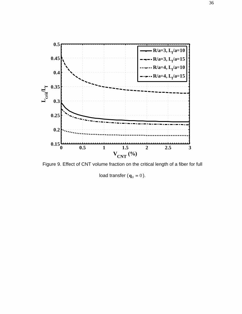
Figure 8 and Figure 9. In Figure 9 the effect of CNT volume fraction on the critical length
( ) of the fiber is presented. Here, is measured from the center of the fiber and
determined based on the situation when of the maximum value of . It may
be noted from this figure that as the CNT volume fraction increases, the critical length of
the fiber decreases rapidly in the region V
critL critL
*σ %98= *σ
%.01CNT < and then decreases
monotonically. For a particular value of volume fraction of the carbon fiber, the critical
length increases if the aspect ratio of the fiber increases, while for a particular value of
aspect ratio of the fiber this critical length decreases with the increase in the volume
fraction of the carbon fiber. In Figure 10 a critical value of is shown to exist
beyond which the radial orthotropy of the PNC matrix does not appreciably alter load
sharing capability of the fiber. After ~2% , there is little change in the load sharing
between the PNC matrix and the fiber.
CNTV
CNTV
Variations of maximum values of the axial stress in the carbon fiber coated with

18
radially aligned CNTs ( =1.0%) and the interface shear stress with the aspect ratio
of the fiber are presented in Figure 11. The maximum value of the axial load shared by
the fiber increases sharply with the increase in the value of the aspect ratio as long as
. For , the axial load sharing capability of the fiber becomes
independent of the variation of the aspect ratio of the fiber. In case of interface shear
stress, its maximum value also increases rapidly with the increase in the value of the
aspect ratio of the fiber till
CNTV
20>12<a/Lf a/Lf
8<a/Lf . The maximum value of becomes saturated for
.
*τ
10>a/Lf
The effect of application of radial load on the load transferred to the fiber is
presented in Figure 12. If the applied radial load is compressive, then the maximum
values of the axial normal stress in the fiber and the interface shear stress are higher
than those without the application of radial load ( 00 =q ), and vice versa. The variations
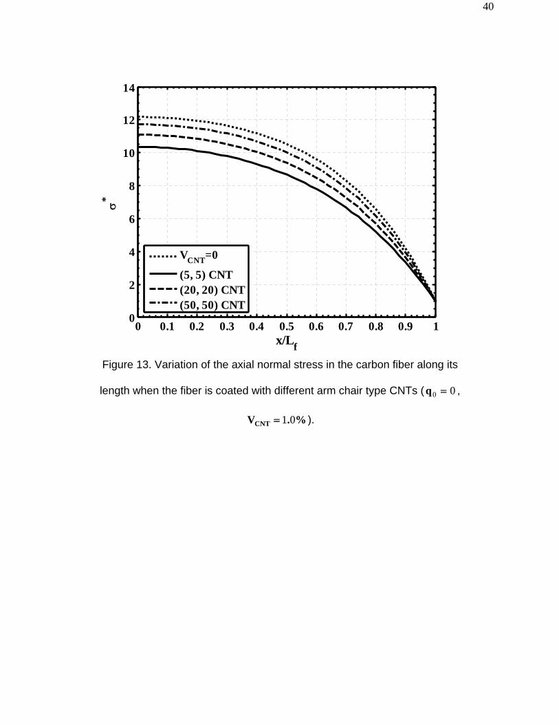
of axial normal stress in the carbon fiber and the interface shear stress along its length
are presented in Figure 13 and Figure 14, respectively, for different arm chair type
CNTs in Table 1. It may be observed from these figures that for a particular value of
, as the diameter of CNT increases, both the axial normal load transferred to the
fiber and the interface shear stress increase. This may be attributed to the fact that as
the diameter of CNT increases, elastic coefficients of CNT decreases (see Table 1)
which results in the decrease in the values of the effective elastic properties of the CNT-
reinforced PNC matrix. Overall, the type of CNT has a small effect on the composite
fiber load sharing relative to varying volume fraction of the CNTs in the PNC matrix.
CNTV

19
4. Conclusions
In this paper, load sharing in a shortfiber composite where the matrix is reinforced with
radially-aligned CNTs has been analyzed. The fiber reinforcement of the composite is a
discontinuous carbon fiber coated with radially aligned CNTs. A shear lag model
considering radial and axial deformations of the different phases of the RVE has been
developed to analyze the axial load transferred to this carbon fiber. Since the radially
aligned CNTs grown on the carbon fiber reinforce the polymer matrix, the effective
elastic properties of the resulting CNT-reinforced PNC matrix are modified. Hence, if the
fiber is coated with CNTs, the axial load transferred to the carbon fiber and the shear
stress at the interface between the fiber and the PNC matrix decrease, and the CNT-
reinforced matrix carries more of this load. If the volume fraction of CNTs increases,
both the axial load transferred to the fiber and the interface shear stress decrease,
including importantly the maximum shear stress at the fiber-matrix interface. The critical
length of the carbon fiber varies little with CNT volume fraction beyond a few percent.
For a particular value of CNT volume fraction, compressive radial load applied to the
RVE increases the axial load transferred to the fiber and the interface shear stress.
Future work should consider load-transfer in randomly-oriented shortfiber composites,
and also load transfer around a broken fiber in continuous filament composites, in
addition to load sharing in the presence of applied shear stress.

20
Appendix
The various matrices appearing in Eq. (29) are given by
⎥⎥⎥⎥⎥⎥⎥⎥
⎦
⎤
⎢⎢⎢⎢⎢⎢⎢⎢
⎣
⎡
=
000000000000000000000000000000000
3323131
nnn
nCCC
v]C[ , ,
⎥⎥⎥⎥⎥⎥⎥⎥
⎦
⎤
⎢⎢⎢⎢⎢⎢⎢⎢
⎣
⎡
=
p
p
p
pp
pp
pp
ppp
ppp
CC
CCvCvCv
CCCCCC
]C[
44
44
44
111212
121112
121211
2
000000000000000000000000
CNTn VaR
Rv 22
2
−= , , , , np vv −= 1 ]C[]C][V[]V[]V[ 3
14213
−+= ]C[]C][V[]V[]V[ 41
3124−+=
⎥⎥⎥⎥⎥⎥⎥⎥
⎦
⎤
⎢⎢⎢⎢⎢⎢⎢⎢
⎣
⎡
=
n
n
n
nnn
nnn
CC
C
CCCCCC
]C[
66
55
44
232212
131211
3
000000000000000000100000000
, ,
⎥⎥⎥⎥⎥⎥⎥⎥
⎦
⎤
⎢⎢⎢⎢⎢⎢⎢⎢
⎣
⎡
=
p
p
p
ppp
ppp
CC
C
CCCCCC
]C[
44
44
44
121112
121211
4
000000000000000000100000000
and
(2)
⎥⎥⎥⎥⎥⎥⎥⎥
⎦
⎤
⎢⎢⎢⎢⎢⎢⎢⎢
⎣
⎡
=
n
n
n
n
n
vv
v
vv
]V[
0000000000000000000000000000000
1
⎥⎥⎥⎥⎥⎥⎥⎥
⎦
⎤
⎢⎢⎢⎢⎢⎢⎢⎢
⎣
⎡
=
p
p
p
p
p
vv
v
vv
]V[
0000000000000000001000000000000
2

21
In the above matrices, and are the elastic coefficients of the CNT and the
polymer material, respectively. The volume fractions of the polymer and the CNT with
respect to the volume of the PNC are represented by and while denotes
the volume fraction of CNTs with respect to the volume of the RVE.
nijC p
ijC
pv nv CNTV

22
References
1S. Iijima, Helical microtubules of graphitic carbon, Nature 1991, 354, 56-58.
2M. M. J. Treacy, T. W. Ebbessen, J. M. Gibson, Exceptionally high Young's modulus
observed for individual carbon nanotubes, Nature 1996, 381, 678 - 680.
3C. Li, T. W. Chou, A structural mechanics approach for the analysis of carbon
nanotubes, International Journal of Solids Structures 2003, 40, 2487 - 2499.
4A. Sears, R. C. Batra, Macroscopic properties of carbon nanotubes from molecular
mechanics simulations, Physical Review B 2004, 69, 1-10.
5L. Shen, J. Li, Transversely isotropic elastic properties of single-walled carbon
nanotubes, Physical Review B 2004, 69, 1-10.
6R. C. Batra, A. Sears, Uniform radial expansion/contraction of carbon nanotubes and
their transverse elastic moduli, Modelling and Simulation in Materials Science and
Engineering 2007, 15, 835-844.
7J. Wu, K. C. Hwang, Y. Huang, An atomistic-based finite-deformation shell theory for
single-wall carbon nanotubes, Journal of the Mechanics and Physics of Solids 2008, 56,
279-292.
8E. T. Thostenson, T. W. Chou, On the elastic properties of carbon nanotube based
composites: modeling and characterization, Journal of Physics D: Applied Physics
2003, 36, 573-582.
9X. L. Gao, K. Li, A shear-lag model for carbon nanotube reinforced polymer
composites, International Journal of Solids and Structures 2005, 42, 1649-1667.
10Y. S. Song, J. R. Youn, Modeling of effective elastic properties for polymer based
carbon nanotube composites, Polymer 2006, 47, 1741-1748.

23
11G. D. Seidel, D. C. Lagoudas, Micromechanical analysis of the effective elastic
properties of carbon nanotube reinforced composites, Mechanics of materials 2006, 38,
884-907.
12R. Guzman de Villoria, A. Miravete, Mechanical model to evaluate the effect of the
dispersion in nanocomposites, Acta Materialia 2007, 55, 3025-3031.
13L. Y. Jiang, H. L. Tan, J. Wu, Y. G. Huang, K. C. Hwang, Continuum modeling of
interfaces in polymer matrix composites reinforced by carbon nanotubes, Nano Letters
2007, 2, 139-148.
14G. M. Odegard, T. S. Gates, K. E. Wise, C. Park, E. J. Siochi, Constitutive modeling of
nanotube-reinforced polymer composites, Composites Science and Technology 2003,
63, 1671-1687.
15G. M. Odegard, T. S. Gates, L. M. Nicholson, K. E. Wise, Equivalent-Continuum
Modeling of Nano-Structured Materials, Composites Science and Technology 2002, 62,
1869-1880.
16V. I. Yamakov, E. H. Glaessegen, To twin or not to twin, Nature Materials 2007, 6,
795-796.
17J. Zhang, C. He, A three-phase cylindrical shear-lag model for carbon nanotube
composites, Acta Mechanica 2008, 196, 33-54.
18M. C. Ray, R. C. Batra, Effective properties of carbon nanotube and piezoelectric fiber
reinforced hybrid smart composite, accepted in ASME Journal of Applied mechanics
2008.
19E. T. Thostenson, C. Li, T.-W. Chou, Nanocomposites in context, Composites Science
and Technology 2005, 65, 491-516.

24
20E. T. Thostenson, Z. Ren, T.-W. Chou, Advances in the science and technology of
carbon nanotubes and their composites: a review, Composites Science and Technology
2001, 61, 1899-1912.
21J. N. Coleman, U. Khan, W. J. Blau, Y. K. Gun'ko, Small but strong: A review of the
mechanical properties of carbon nanotube-polymer composites, Carbon 2006, 44,
1624-1652.
22J. O. Zhao, L. Liu, Q. G. Guo, J. Shi , G. Zhai , J. Song, Z. Liu, Growth of carbon
nanotubes on the surface of carbon fibers, Carbon 2008, 46, 380-383.
23Q. J. Gong, H. J. Li, X. Wang, Q. G. Fua, Z. W. Wanga, K. Z. Lia, In situ catalytic
growth of carbon nanotubes on the surface of carbon cloth, Composite Science and
Technology 2007, 67, 2986-2989.
24L. T. Qu, Y. Zhao, L. M. Dai, Carbon microfibers sheathed with aligned carbon
nanotubes: Towards multidimensional, multicomponent, and multifunctional
nanomaterials, Small 2006, 2, 1052-1059.
25L. J. Ci, Z. G. Zhao, J. B. Bai, Direct growth of carbon nanotubes on the surface of
ceramic fibers, Carbon 2005, 43, 883-886.
26Z. G. Zhao, L. J. Ci, H. M. Cheng, J. B. Bai, The growth of multi-walled carbon
nanotubes with different morphologies on carbon fibers, Carbon 2005, 43, 663-665.
27R. B. Mathur, S. Chatterjee, B. P. Singh, Growth of carbon nanotubes on carbon fibre
substrates to produce hybrid/phenolic composites with improved mechanical properties,
Composite Science and Technology 2008, 68, 1608-1615.
25
28V. P. Veedu, A. Cao, X. Li, K. Ma, C. Soldano, S. Kar, P. M. Ajayan, M. N. Ghasemi-
Nejhad, Multifunctional Composites Using Reinforced Laminae with Carbon Nanotube
Forests, Nature Materials 2006, 5, 457-462.
29E. J. Garcia, B. L. Wardle, A. J. Hart, N. Yamamoto, Fabrication and Multifunctional
Properties of a Hybrid Laminate with Aligned Carbon Nanotubes Grown In Situ,
Composites Science & Technology 2008, 68, 2034-2041.
30E. J. García, A. J. Hart, B. L. Wardle, A. H. Slocum, Fabrication of composite
microstructures by capillarity-driven wetting of aligned carbon nanotubes with polymers,
Nanotechnology 2007, 18, 165602 (165611 pp).
31K. I. Winey, R. A. Vaia, Polymer Nanocomposites, MRS Bulletin 2007, 32, 314-322.
32P. Ajayan, P. Braun, L. Schadler, Nanocomposite Science and Technology, 2003.
33Z. Hashin, W. Rosen, The elastic moduli of fiber reinforced materials, Journal of
Applied Mechanics 1964, 31, 223-232.
34J. D. H. Hughes, The carbon fiber/epoxy interface - a review, Composite Science and
Technology 1991, 41, 13-45.

26
List of tables
Table 1. Material properties of CNTs (Ref. 5). The 3-axis is aligned with the long
axis of the CNT.
CNT
Type
nC11
(GPa)
nC22
(GPa)
nC33
(GPa)
nC12
(GPa)
nC13
(GPa)
nC44
(GPa)
nC55
(GPa)
nC66
(GPa)
(5,5) 668 668 2143 404 184 791 791 132
(10,10) 288 288 1088 254 87.7 442 442 17
(20,20) 138 138 545 134 43.5 227 227 2
(50,50) 55.1 55.1 218 54.9 17.5 92 92 0.1
27
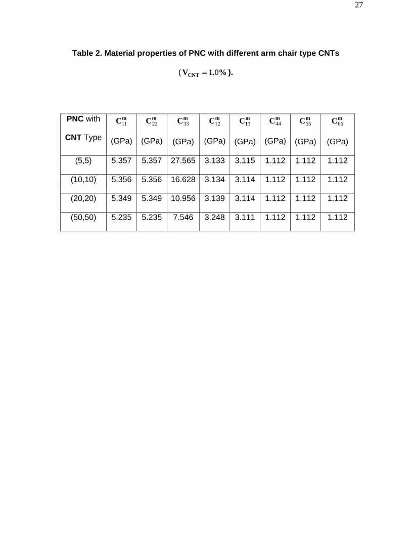
Table 2. Material properties of PNC with different arm chair type CNTs
( %.VCNT 01= ).
PNC with
CNT Type
mC11 22 33 12 13 44 55 66
(GPa)
mC
(GPa)
mC
(GPa)
mC
(GPa)
mC
(GPa)
mC
(GPa)
mC
(GPa)
mC
(GPa)
(5,5) 5.357 5.357 27.565 3.133 3.115 1.112 1.112 1.112
(10,10) 5.356 5.356 16.628 3.134 3.114 1.112 1.112 1.112
(20,20) 5.349 5.349 10.956 3.139 3.114 1.112 1.112 1.112
(50,50) 5.235 5.235 7.546 3.248 3.111 1.112 1.112 1.112
28
List of figures
Carbon fiber
Aligned CNTs
100 μm 50 μm
Aligned CNTs
Alumina fiber location
Figure 1. Fibers coated with in situ grown radially aligned CNTs. Fuzzy alumina (left)
and carbon fiber (right).

29
qo
σ0 σ0
y
x z
Figure 2. Model nano-engineered composite with representative volume element
(RVE) indicated at the center.

30
x
r
2R2a
Carbon FiberCNTs
EpoxyLL
σ σ
f f
L L
q
q
r
CNTs Epoxy
Carbon Fiber
Transverse Cross-Section
Longitudinal Cross-Section
θ
0
0
0
0
Figure 3. RVE of the composite containing a fiber reinforcement coated with radially-
aligned CNTs.

31
0 1 2 3 4 5 6 70
4
8
12
16
20
24
x/2a
σ∗ &
τ∗ σ*, Present
τ*, Presentσ*, Ref. [10]τ*, Ref. [10]
Figure 4. Model validation by comparison to Ref.9 for the case of an isotropic matrix
phase (no CNTs) around the fiber. =10 a/Lf

32
0 0.1 0.2 0.3 0.4 0.5 0.6 0.7 0.8 0.9 10
2
4
6
8
10
12
14
16
18
20
x/Lf
σ* &
τ*
σ*, VCNT=0
σ*, VCNT=1.0%
τ*, VCNT=0
τ*, VCNT=1.0%
Figure 5. Variation of normalized axial normal stress in the carbon fiber and
the interface shear stress along the fiber length ( 00 =q ).

33
0 0.1 0.2 0.3 0.4 0.5 0.6 0.7 0.8 0.9 10
2
4
6
8
10
12
14
x/Lf
σ*
PNC, VCNT=0
PNC, VCNT=0.5%
PNC, VCNT=1.5%
Isotropic Stiff Matrix
Figure 6. Variation of axial normal stress in the carbon fiber along its length
( 00 =q )

34
0 0.1 0.2 0.3 0.4 0.5 0.6 0.7 0.8 0.9 10
2
4
6
8
10
12
14
16
18
20
x/Lf
τ*PNC, VCNT=0
PNC, VCNT=0.5%
PNC, VCNT=1.5%
Isotropic stiff matrix
Figure 7. Variation of transverse shear stress at the interface between the
matrix and the carbon fiber along the length of the fiber for different CNT
volume fraction and considering isotropic stiffening of the matrix (
00 =q ).

35
0 0.1 0.2 0.3 0.4 0.5 0.6 0.7 0.8 0.9 10
2
4
6
8
10
12
14
x/Lf
σ*
R/a=3, VCNT=0
R/a=3, VCNT=1.0%
R/a=4, VCNT=0
R/a=4, VCNT=1.0%
Figure 8. Load transfer in the carbon fiber for different values of a/R
( %.VCNT 01= , 00 =q )
36
0 0.5 1 1.5 2 2.5 30.15
0.2
0.25
0.3
0.35
0.4
0.45
0.5
VCNT (%)
L crit/L
fR/a=3, Lf/a=10
R/a=3, Lf/a=15
R/a=4, Lf/a=10
R/a=4, Lf/a=15
Figure 9. Effect of CNT volume fraction on the critical length of a fiber for full
load transfer ( 00 =q ).

37
0 0.5 1 1.5 2 2.5 310
11
12
13
14
15
16
17
18
19
VCNT (%)
max
( σ* , τ
* )σ
*
τ*
Figure 10. Variation of maximum axial stress and interfacial shear stress on the carbon
fiber ( ) as a function of CNT volume fraction ( ). 10=a/f_L 00 =q

38
0 5 10 15 20 25 30 35 40 45 500
2
4
6
8
10
12
14
16
18
20
Aspect Ratio (Lf/a)
max
( σ* , τ
* )
σ*, VCNT=0
σ*, VCNT=1.0%
σ*, VCNT=0
σ*, VCNT=1.0%
Figure 11. Variation of maximum values of the axial normal stress and the
transverse shear stress at the interface between the matrix and the carbon
fiber with the aspect ratio of the fiber ( 00 =q , %.VCNT 01= ).

39
-0.8 -0.6 -0.4 -0.2 0 0.2 0.4 0.6 0.88
10
12
14
16
18
20
Normalized radial load (q0/σ0)
max
( σ* , τ
* )σ
*
τ*
Figure 12. Variation of maximum values of the axial normal stress and the transverse
shear stress at the interface between the matrix and the carbon fiber with the applied
radial load ( 10=a/Lf , %.VCNT 01= ).
40
0 0.1 0.2 0.3 0.4 0.5 0.6 0.7 0.8 0.9 10
2
4
6
8
10
12
14
x/Lf
σ*
VCNT=0
(5, 5) CNT(20, 20) CNT(50, 50) CNT
Figure 13. Variation of the axial normal stress in the carbon fiber along its
length when the fiber is coated with different arm chair type CNTs ( 00 =q ,
%.VCNT 01= ).

41
0 0.1 0.2 0.3 0.4 0.5 0.6 0.7 0.8 0.9 10
2
4
6
8
10
12
14
16
18
20
x/Lf
τ*VCNT=0
(5, 5) CNT(20, 20) CNT(50, 50) CNT
Figure 14. Variation of the transverse shear stress at the interface between
the matrix and the carbon fiber along its length when the fiber is coated with
different arm chair type CNTs ( 00 =q , %.VCNT 01= ).


![Compression Characterization of High-modulus Carbon Fibers...High modulus carbon fibers, such as Dialead fibers, are very stiff. A quasi-isotropic ([0 ,90 ,45 ,-45 ] S) material reinforced](https://img.pdfslide.us/doc/110x75/60bef11d8565e13c36101f20/compression-characterization-of-high-modulus-carbon-fibers-high-modulus-carbon.jpg)