Embed Size (px)
Citation preview
THE ROSETTA LANDER ANCHORING SYSTEM
Markus Thiel 1), Jakob Stöcker 1), Christian Rohe 1), Norbert I. Kömle 2), Günter Kargl 2), Olaf Hillenmaier 3), Peter Lell 4)
1) Max-Planck-Institut für extraterrestrische Physik, Garching, Germany 2) Space Research Institute, Austrian Academy
of Sciences, Graz, Austria 3) Magson GmbH, Berlin, Germany 4) Pyroglobe GmbH, Hettenshausen, Germany
Address of principal author: Max-Planck-Institut für extraterrestrische Physik, Giessenbachstraße, D-85748 Garching, Phone: +49-(0)89-30000-3395, Fax: +49-(0)89-30000-3569, e-mail: [email protected]
ABSTRACT Central part of Landing Gear
A major goal of the ESA cornerstone mission ROSETTA is to land a package of scientific instruments known as the ROSETTA Lander on the nucleus of a comet. Due to the low gravity a highly reliable fixation of the ROSETTA Lander to the target comet 67P/Churyumov-Gerasimenko (3rd) is essential. For that purpose a redundant Anchoring System, consisting of two pyrotechnically actuated Anchoring Harpoons and a redundant Control Electronics has been developed, built and qualified at the Max-Planck-Institut für extrater-restrische Physik (MPE), Garching.
(MPAe Katlenburg-Lindau)
Harpoon 1
Distance keeperHarpoon 2
Distance keeper
The pyrotechnical gas generator has been developed jointly by Pyroglobe GmbH and MPE, the procurement of the control electronics has been sub-contracted to Magson GmbH, Berlin. A study to obtain a suitable lubrication method for the commutator of a brushed DC motor has been conducted at the European Space Tri-bology Laboratory (ESTL; S. D. Lewis et al., 2003).
Fig. 1:Mounting positions of Anchoring Harpoons
One harpoon (the default unit) shall be fired automati-cally upon touchdown of the ROSETTA Lander on the comet nucleus. The firing of the harpoon is triggered by a touchdown signal generated by the Landing Gear. The anchor cable is pulled out from a cable magazine which is mounted beside the expansion cylinder. Immediately after the firing the Rewind System is operated automati-cally to spool up the cable and tighten the Lander to the comet surface. The tightening force is commandable in eight steps. A freewheeling mechanism maintains the cable tension after the rewind actuator is switched off. A motor-driven unlocking clutch allows to release the cable tension. An identical second harpoon is available in case of failure of the default unit.
1. INTRODUCTION
The design of the Anchoring System is governed by extraordinary requirements arising from its outstanding importance for the success of the mission, from a long cruise phase of more than ten years, low temperatures (-160 ... -190°C) and from strict power and mass restric-tions (1.5 kg subsystem mass). To meet these require-ments several sub-units had to be either specifically developed or optimized for this application and numer-ous development tests had to be performed. Two miniature sensors are implemented in each of the
anchoring projectiles as part of the MUPUS instrument (Multi Purpose Sensor for Surface and Sub-Surface Science): A shock accelerometer measuring the accel-eration and deceleration of the projectile during the anchor shot and a temperature sensor (PT100) to meas-ure temperature variations below the surface over at least several rotation periods of the comet (Kömle et. al., 1997, 2001; Kargl et al., 2001).
2. SUBSYSTEM CONCEPT
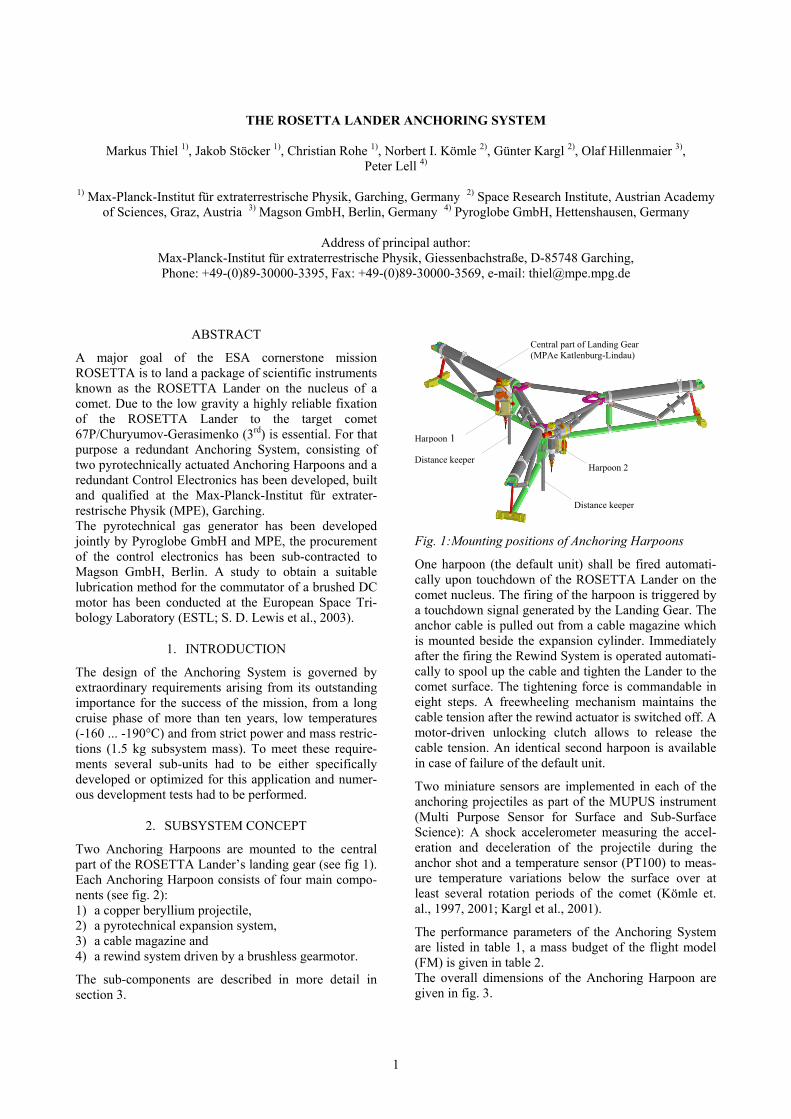
Two Anchoring Harpoons are mounted to the central part of the ROSETTA Lander’s landing gear (see fig 1). Each Anchoring Harpoon consists of four main compo-nents (see fig. 2): 1) a copper beryllium projectile, 2) a pyrotechnical expansion system, The performance parameters of the Anchoring System
are listed in table 1, a mass budget of the flight model (FM) is given in table 2.
3) a cable magazine and 4) a rewind system driven by a brushless gearmotor.
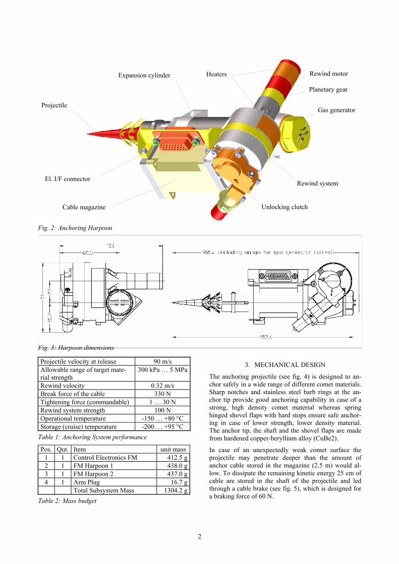
The overall dimensions of the Anchoring Harpoon are given in fig. 3.
The sub-components are described in more detail in section 3.
1
Heaters
Planetary gear
El. I/F connector
Gas generator
Cable magazine Unlocking clutch
Rewind system
Rewind motor Expansion cylinder
Projectile
Fig. 2: Anchoring Harpoon
Fig. 3: Harpoon dimensions
Projectile velocity at release 90 m/s Allowable range of target mate-rial strength
300 kPa … 5 MPa
Rewind velocity 0.32 m/s Break force of the cable 330 N Tightening force (commandable) 1 … 30 N Rewind system strength 100 N Operational temperature -150 … +80 °C Storage (cruise) temperature -200 … +95 °C
3. MECHANICAL DESIGN
The anchoring projectile (see fig. 4) is designed to an-chor safely in a wide range of different comet materials. Sharp notches and stainless steel barb rings at the an-chor tip provide good anchoring capability in case of a strong, high density comet material whereas spring hinged shovel flaps with hard stops ensure safe anchor-ing in case of lower strength, lower density material. The anchor tip, the shaft and the shovel flaps are made from hardened copper-beryllium alloy (CuBe2). Table 1: Anchoring System performance
Pos. Qut. Item unit mass 1 1 Control Electronics FM 412.5 g2 1 FM Harpoon 1 438.0 g3 1 FM Harpoon 2 437.0 g4 1 Arm Plug 16.7 g Total Subsystem Mass 1304.2 g
In case of an unexpectedly weak comet surface the projectile may penetrate deeper than the amount of anchor cable stored in the magazine (2.5 m) would al-low. To dissipate the remaining kinetic energy 25 cm of cable are stored in the shaft of the projectile and led through a cable brake (see fig. 5), which is designed for a braking force of 60 N.
Table 2: Mass budget
2
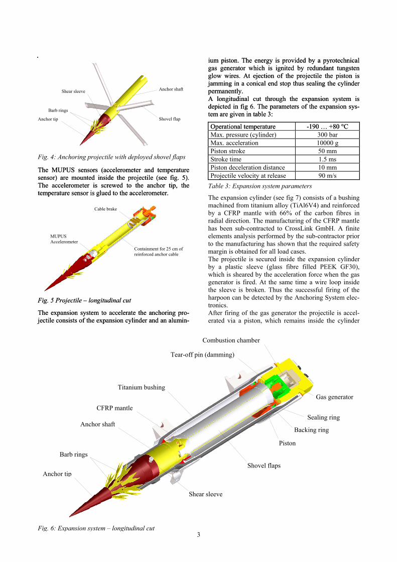
Fig. 4: Anchoring projectile with deployed shovel flaps
The MUPUS sensors (accelerometer and temperature sensor) are mounted inside the projectile (see fig. 5). The accelerometer is screwed to the anchor tip, the temperature sensor is glued to the accelerometer.
The MUPUS sensors (accelerometer and temperature sensor) are mounted inside the projectile (see fig. 5). The accelerometer is screwed to the anchor tip, the temperature sensor is glued to the accelerometer.
Fig. 5 Projectile – longitudinal cut Fig. 5 Projectile – longitudinal cut
The expansion system to accelerate the anchoring pro-jectile consists of the expansion cylinder and an alumin-
ium piston. The energy is provided by a pyrotechnical gas generator which is ignited by redundant tungsten glow wires. At ejection of the projectile the piston is jamming in a conical end stop thus sealing the cylinder permanently.
The expansion system to accelerate the anchoring pro-jectile consists of the expansion cylinder and an alumin-
ium piston. The energy is provided by a pyrotechnical gas generator which is ignited by redundant tungsten glow wires. At ejection of the projectile the piston is jamming in a conical end stop thus sealing the cylinder permanently. Anchor shaft Shear sleeve
A longitudinal cut through the expansion system is depicted in fig 6. The parameters of the expansion sys-tem are given in table 3:
A longitudinal cut through the expansion system is depicted in fig 6. The parameters of the expansion sys-tem are given in table 3:
Barb rings
Shovel flap Anchor tip
Operational temperature Operational temperature -190 … +80 °C -190 … +80 °C Max. pressure (cylinder) 300 bar Max. acceleration 10000 g Piston stroke 50 mm Stroke time 1.5 ms Piston deceleration distance 10 mm Projectile velocity at release 90 m/s
Table 3: Expansion system parameters
The expansion cylinder (see fig 7) consists of a bushing machined from titanium alloy (TiAl6V4) and reinforced by a CFRP mantle with 66% of the carbon fibres in radial direction. The manufacturing of the CFRP mantle has been sub-contracted to CrossLink GmbH. A finite elements analysis performed by the sub-contractor prior to the manufacturing has shown that the required safety margin is obtained for all load cases.
Cable brake
MUPUS Accelerometer
Containment for 25 cm of reinforced anchor cable
The projectile is secured inside the expansion cylinder by a plastic sleeve (glass fibre filled PEEK GF30), which is sheared by the acceleration force when the gas generator is fired. At the same time a wire loop inside the sleeve is broken. Thus the successful firing of the harpoon can be detected by the Anchoring System elec-tronics. After firing of the gas generator the projectile is accel-erated via a piston, which remains inside the cylinder
Combustion chamber
Backing ring
Tear-off pin (damming)
Barb rings
Anchor tip Shovel flaps
Shear sleeve
Anchor shaft
Gas generator
Sealing ring
Piston
Titanium bushing
CFRP mantle
3Fig. 6: Expansion system – longitudinal cut
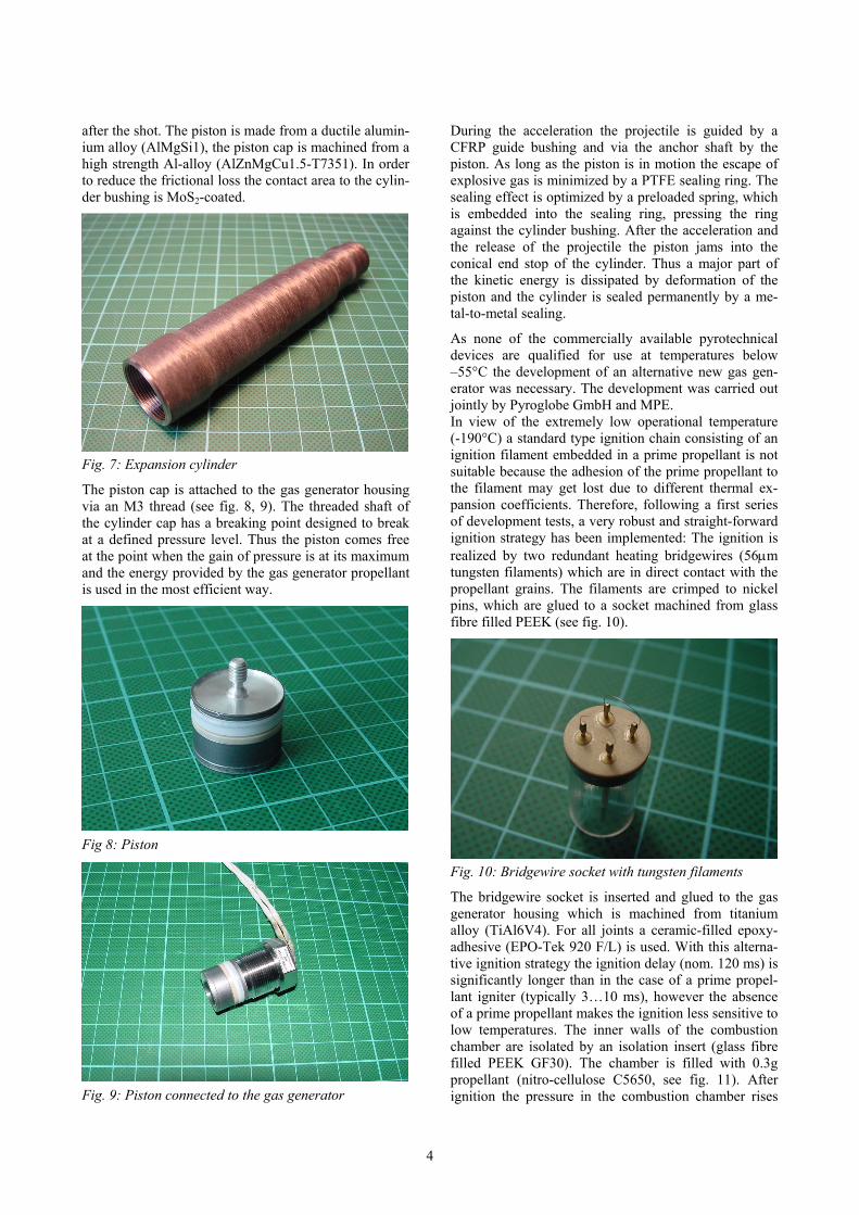
after the shot. The piston is made from a ductile alumin-ium alloy (AlMgSi1), the piston cap is machined from a high strength Al-alloy (AlZnMgCu1.5-T7351). In order to reduce the frictional loss the contact area to the cylin-der bushing is MoS2-coated.
During the acceleration the projectile is guided by a CFRP guide bushing and via the anchor shaft by the piston. As long as the piston is in motion the escape of explosive gas is minimized by a PTFE sealing ring. The sealing effect is optimized by a preloaded spring, which is embedded into the sealing ring, pressing the ring against the cylinder bushing. After the acceleration and the release of the projectile the piston jams into the conical end stop of the cylinder. Thus a major part of the kinetic energy is dissipated by deformation of the piston and the cylinder is sealed permanently by a me-tal-to-metal sealing.
As none of the commercially available pyrotechnical devices are qualified for use at temperatures below –55°C the development of an alternative new gas gen-erator was necessary. The development was carried out jointly by Pyroglobe GmbH and MPE. In view of the extremely low operational temperature (-190°C) a standard type ignition chain consisting of an ignition filament embedded in a prime propellant is not suitable because the adhesion of the prime propellant to the filament may get lost due to different thermal ex-pansion coefficients. Therefore, following a first series of development tests, a very robust and straight-forward ignition strategy has been implemented: The ignition is realized by two redundant heating bridgewires (56µm tungsten filaments) which are in direct contact with the propellant grains. The filaments are crimped to nickel pins, which are glued to a socket machined from glass fibre filled PEEK (see fig. 10).
Fig. 7: Expansion cylinder
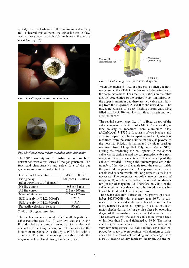
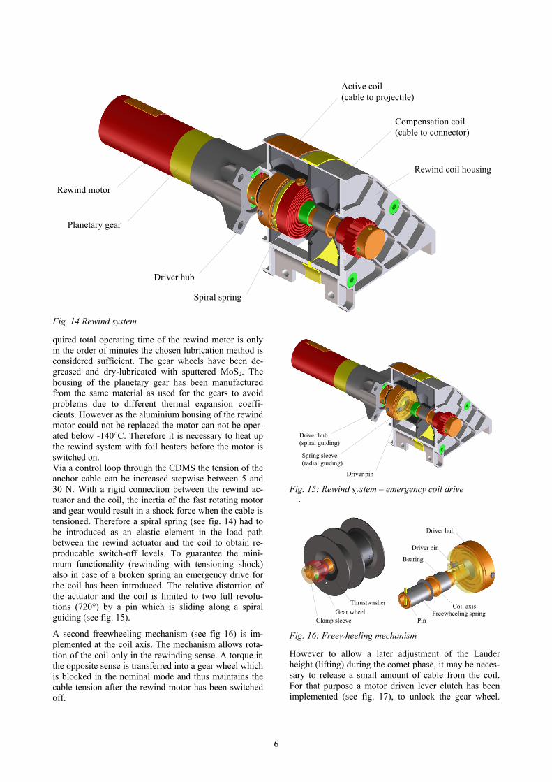
The piston cap is attached to the gas generator housing via an M3 thread (see fig. 8, 9). The threaded shaft of the cylinder cap has a breaking point designed to break at a defined pressure level. Thus the piston comes free at the point when the gain of pressure is at its maximum and the energy provided by the gas generator propellant is used in the most efficient way.
Fig 8: Piston
Fig. 10: Bridgewire socket with tungsten filaments
The bridgewire socket is inserted and glued to the gas generator housing which is machined from titanium alloy (TiAl6V4). For all joints a ceramic-filled epoxy-adhesive (EPO-Tek 920 F/L) is used. With this alterna-tive ignition strategy the ignition delay (nom. 120 ms) is significantly longer than in the case of a prime propel-lant igniter (typically 3…10 ms), however the absence of a prime propellant makes the ignition less sensitive to low temperatures. The inner walls of the combustion chamber are isolated by an isolation insert (glass fibre filled PEEK GF30). The chamber is filled with 0.3g propellant (nitro-cellulose C5650, see fig. 11). After ignition the pressure in the combustion chamber rises Fig. 9: Piston connected to the gas generator
4
quickly to a level where a 100µm aluminium damming foil is sheared thus allowing the explosive gas to flow over to the cylinder via eight 0.7-mm holes in the nozzle insert (see fig. 12).
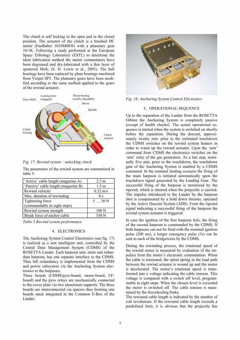
Magazine A (anchor cable)
Magazine B (compensation cable)
Fig. 13: Cable magazine (with rewind system) PTFE foil
When the anchor is fired and the cable pulled out from magazine A, the PTFE foil offers only little resistance to the cable movement. Thus the tensile stress on the cable and the deceleration of the projectile are minimized. At the upper aluminium cap there are two cable exits lead-ing from the magazines A and B to the rewind coil. The magazine consists of a case machined from glass fibre filled PEEK (GF30) with Helicoil thread inserts and two aluminium caps.
Fig. 11: Filling of combustion chamber
The rewind system (see fig. 14) is fixed on top of the cable magazine with four bolts M2.5. The rewind sys-tem housing is machined from aluminium alloy (AlZnMgCu1.5–T7351). It consists of two brackets and a central separator. The two-part rewind coil, which is machined from the same aluminium alloy, is pivoted to the housing. Friction is minimized by plain bearings machined from MoS2-filled Polyimide (Vespel SP3). During the rewinding the coil spools up the anchor cable via magazine A and the compensation cable from magazine B at the same time. Thus a twisting of the cable is avoided. Through the uninterrupted cable the transfer of the electrical signals from the sensors inside the projectile is guaranteed. A slip ring, which is not considered reliable within this long-term mission is not necessary. The compensation coil diameter (on top of magazine B) is only about half of the rewind coil diame-ter (on top of magazine A). Therefore only half of the cable length in magazine A has to be stored in magazine B and the total cable length is minimized.
Fig. 12: Nozzle insert (right: with aluminium damming)
The ESD sensitivity and the no-fire current have been determined with a test series of the gas generator. The functional characteristics and safety data of the gas generator are summarized in table 3.
Operational temperature -190 … +80 °C Firing delay (after powering of 1st filament)
120 (nom.) … 410 ms
No fire current 0.5 A / 5 min All fire current 2.2 A / 200 ms Nominal fire current 2.5 A / 120 ms ESD sensitivity (5 kΩ, 500 pF) > 25kV ESD sensitivity (0 kΩ, 500 pF) > 10kV Projectile velocity at release 90 m/s
The rewind actuator, a brushless DC gearmotor (Faul-haber 1628T024B with planetary gear 16/7), is con-nected to the rewind coils via a freewheeling mecha-nism, realized by a helicoil spring. This solution allows motor checks during the long cruise phase by operating it against the rewinding sense without driving the coil. The actuator allows the anchor cable to be wound back within less than 8 s and tightened to 30 N. The motor and the gear have been modified for use in vacuum at very low temperature: All ball bearings have been re-placed by space proven bearings with titanium carbide-coated balls to avoid cold-welding and steel cages with a PTFE-coating as dry lubricant reservoir. As the re-
Table 3: Gas generator data
The anchor cable is stored twistfree (8-shaped) in a cable magazine (see fig. 13) with two sections (A and B) and is led via a two-part rewind coil to the electrical connector without any interruption. The cable exit at the bottom of magazine A is shut by a PTFE foil with a cross cut. This foil is securing the cable inside the magazine at launch and during the cruise phase.
5
Spiral spring
Driver hub
Rewind coil housing
Planetary gear
Rewind motor
Compensation coil (cable to connector)
Active coil (cable to projectile)
Fig. 14 Rewind system
quired total operating time of the rewind motor is only in the order of minutes the chosen lubrication method is considered sufficient. The gear wheels have been de-greased and dry-lubricated with sputtered MoS2. The housing of the planetary gear has been manufactured from the same material as used for the gears to avoid problems due to different thermal expansion coeffi-cients. However as the aluminium housing of the rewind motor could not be replaced the motor can not be oper-ated below -140°C. Therefore it is necessary to heat up the rewind system with foil heaters before the motor is switched on. Via a control loop through the CDMS the tension of the anchor cable can be increased stepwise between 5 and 30 N. With a rigid connection between the rewind ac-tuator and the coil, the inertia of the fast rotating motor and gear would result in a shock force when the cable is tensioned. Therefore a spiral spring (see fig. 14) had to be introduced as an elastic element in the load path between the rewind actuator and the coil to obtain re-producable switch-off levels. To guarantee the mini-mum functionality (rewinding with tensioning shock) also in case of a broken spring an emergency drive for the coil has been introduced. The relative distortion of the actuator and the coil is limited to two full revolu-tions (720°) by a pin which is sliding along a spiral guiding (see fig. 15).
A second freewheeling mechanism (see fig 16) is im-plemented at the coil axis. The mechanism allows rota-tion of the coil only in the rewinding sense. A torque in the opposite sense is transferred into a gear wheel which is blocked in the nominal mode and thus maintains the cable tension after the rewind motor has been switched off.
Driver hub (spiral guiding)
Spring sleeve (radial guiding)
Driver pin
Fig. 15: Rewind system – emergency coil drive
Driver hub
Driver pin
Bearing
Thrustwasher Coil axis
Fig. 16: Freewheeling mechanism
However to allow a later adjustment of the Lander height (lifting) during the comet phase, it may be neces-sary to release a small amount of cable from the coil. For that purpose a motor driven lever clutch has been implemented (see fig. 17), to unlock the gear wheel.
Clamp sleeve Gear wheel Freewheeling spring
Pin
6
The clutch is self locking in the open and in the closed position. The actuator of the clutch is a brushed DC motor (Faulhaber 1016M003G with a planetary gear 10/1K. Following a study performed at the European Space Tribology Laboratory (ESTL) to determine the ideal lubrication method the motor commutators have been degreased and dry-lubricated with a thin layer of sputtered MoS2 (S. D. Lewis et al., 2003). The ball bearings have been replaced by plain bearings machined from Vespel SP3. The planetary gears have been modi-fied according to the same method applied to the gears of the rewind actuator.
Thrust bearing Locking lever Fig. 18: Anchoring System Control Electronics (axially adjustable) (engaged) Gear wheel
Driver
5. OPERATIONAL SEQUENCE Spindle
Up to the separation of the Lander from the ROSETTA Orbiter the Anchoring System is completely passive (except of health checks). The actual operational se-quence is started when the system is switched on shortly before the separation. During the descent, approxi-mately twenty min. prior to the estimated touchdown the CDMS switches on the rewind system heaters in order to warm up the rewind actuator. Upon the ‘arm’ command from CDMS the electronics switches on the ‘arm’ relay of the gas generators. As a last step, nomi-nally five min. prior to the touchdown, the touchdown gate of the Anchoring System is enabled by a CDMS command. In the nominal landing scenario the firing of the main harpoon is initiated automatically upon the touchdown signal generated by the Landing Gear. The successful firing of the harpoon is monitored by the ripcord, which is sheared when the projectile is ejected. The impulse introduced to the Lander by the harpoon shot is compensated by a hold down thruster, operated by the Active Descent System (ADS). From the ripcord signal indicating a successful firing of the harpoon the rewind system actuator is triggered.
Clutch housing
Clutch actuator
Fig. 17: Rewind system – unlocking clutch
The parameters of the rewind system are summarized in table 5:
‘Active’ cable length (magazine A) 2.5 m ‘Passive’ cable length (magazine B) 1.5 m Rewind velocity 0.32 m/s Max. duration of rewinding 8 s Tightening force (commandable in eight steps)
5 … 30 N
Rewind system strength 100 N Break force of anchor cable 330 N
In case the ignition of the first harpoon fails, the firing of the second harpoon is commanded by the CDMS. If both harpoons can not be fired with the nominal ignition pulse (200 ms), a longer emergency pulse (3s) can be sent to each of the bridgewires by the CDMS.
Table 5 Rewind system performance
4. ELECTRONICS
The Anchoring System Control Electronics (see fig. 17) is realized as a non intelligent unit, controlled by the Central Data Management System (CDMS) of the ROSETTA Lander. Each harpoon unit, main and redun-dant harpoon, has one separate interface to the CDMS. Thus full redundancy is implemented from the CDMS and power subsystem via the Anchoring System elec-tronics to the harpoons.
During the rewinding process, the rotational speed of the rewind motor is measured by evaluation of the im-pulses from the motor’s electronic commutation. When the cable is tensioned, the spiral spring in the load path between the rewind actuator is wound up and the motor is decelerated. The motor’s rotational speed is trans-formed into a voltage indicating the cable tension. This voltage is compared with a switch off level, program-mable in eight steps. When the chosen level is exceeded the motor is switched off. The cable tension is main-tained by the freewheeling brake.
Three boards (CDMS/pyro-board, motor-board, I/F-board) and the pyro relays are mechanically connected to the cover plate via two aluminium supports. The three boards are interconnected via spacers thus forming one boards stack integrated in the Common E-Box of the Lander. The rewound cable length is indicated by the number of
coil revolutions. If the rewound cable length exceeds a predefined limit, it is obvious that the projectile has
7
N. I. Kömle et al. 1997, Using the anchoring device of a comet lander to determine surface mechanical proper-ties, Planetary and Space Science 45 (1997) 1515-1538
been pulled out from the soil, up to the level of the land-ing gear and thus the anchoring is not safe. In the nominal case a status bit ‘safe anchoring’ is gen-erated. If this status bit has not been generated within a predefined time interval, CDMS must autonomously command the firing of the redundant harpoon.
M. Thiel at al. 1999, The ROSETTA Lander Anchoring System - Subsystem and Scientific Instrument, Pene-trometry in the Solar System, Proceedings of the Inter-national Workshop held in Graz, October 18-20, 1999, Editors: N. I. Kömle, G. Kargl, A. J. Ball, R. D. Lorenz, Verlag der Österreichischen Akademie der Wissen-schaften
To release a small amount of cable from the coil, the motor of the unlocking clutch can be operated via the CDMS. In both the engaged and disengaged position the mechanism is limited by hard stops. At the hard stop the motor current exceeds a switch-off level and the motor is switched off. Günter Kargl et al. 2001, Accelerometry measurements
using the Rosetta Lander's anchoring harpoon: experi-mental set-up, data reduction and signal analysis, Plane-tary and Space Science 49 (2001) 425-435
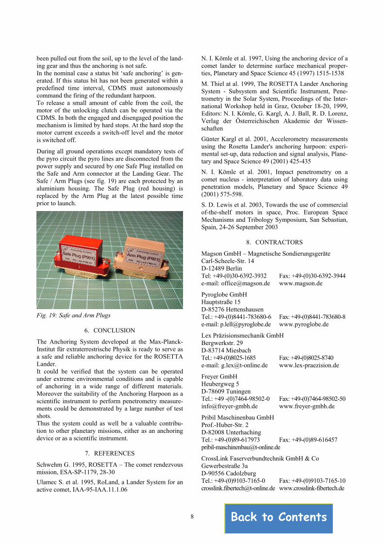
During all ground operations except mandatory tests of the pyro circuit the pyro lines are disconnected from the power supply and secured by one Safe Plug installed on the Safe and Arm connector at the Landing Gear. The Safe / Arm Plugs (see fig. 19) are each protected by an aluminium housing. The Safe Plug (red housing) is replaced by the Arm Plug at the latest possible time prior to launch.
N. I. Kömle et al. 2001, Impact penetrometry on a comet nucleus - interpretation of laboratory data using penetration models, Planetary and Space Science 49 (2001) 575-598.
S. D. Lewis et al. 2003, Towards the use of commercial of-the-shelf motors in space, Proc. European Space Mechanisms and Tribology Symposium, San Sebastian, Spain, 24-26 September 2003
8. CONTRACTORS
Magson GmbH – Magnetische Sondierungsgeräte Carl-Scheele-Str. 14 D-12489 Berlin Tel: +49-(0)30-6392-3932 Fax: +49-(0)30-6392-3944 e-mail: [email protected] www.magson.de
Pyroglobe GmbH Hauptstraße 15 D-85276 Hettenshausen
Fig. 19: Safe and Arm Plugs Tel.: +49-(0)8441-783680-6 Fax: +49-(0)8441-783680-8 e-mail: [email protected] www.pyroglobe.de
6. CONCLUSION Lex Präzisionsmechanik GmbH
The Anchoring System developed at the Max-Planck-Institut für extraterrestrische Physik is ready to serve as a safe and reliable anchoring device for the ROSETTA Lander.
Bergwerkstr. 29 D-83714 Miesbach Tel.: +49-(0)8025-1685 Fax: +49-(0)8025-8740 e-mail: [email protected] www.lex-praezision.de
It could be verified that the system can be operated under extreme environmental conditions and is capable of anchoring in a wide range of different materials. Moreover the suitability of the Anchoring Harpoon as a scientific instrument to perform penetrometry measure-ments could be demonstrated by a large number of test shots.
Freyer GmbH Heubergweg 5 D-78609 Tuningen Tel.: +49 -(0)7464-98502-0 Fax: +49-(0)7464-98502-50 [email protected] www.freyer-gmbh.de
Pribil Maschinenbau GmbH Thus the system could as well be a valuable contribu-tion to other planetary missions, either as an anchoring device or as a scientific instrument.
Prof.-Huber-Str. 2 D-82008 Unterhaching Tel.: +49-(0)89-617973 Fax: +49-(0)89-616457 [email protected]
7. REFERENCES CrossLink Faserverbundtechnik GmbH & Co
Schwehm G. 1995, ROSETTA – The comet rendezvous mission, ESA-SP-1179, 28-30
Gewerbestraße 3a D-90556 Cadolzburg Tel.: +49-(0)9103-7165-0 Fax: +49-(0)9103-7165-10 Ulamec S. et al. 1995, RoLand, a Lander System for an
active comet, IAA-95-IAA.11.1.06 [email protected] www.crosslink-fibertech.de
8