Embed Size (px)
Citation preview

1
The Role Of Control System/Algorithm Subsystems In
Mechatronics Systems Design
Farhan A. Salem1,2
1Mechatronics Engineering Program, Dept. of Mechanical Engineering, College of Engineering,
Taif University, 888, Taif, Saudi Arabia.
2Alpha Center for Engineering Studies and Technology Researches, Amman, Jordan.
ABSTRACT
This paper focuses on control systems and control algorithms subsystems selection, evaluation, design
and synergestic integration stage in Mechatronics systems design and development methodology, main
concepts, classifications, role, description of main features and selection criteria are presented and
discussed. The paper intended to support engineering educators and help students in solving Mechatronics
design and development tasks. Key Words: Mechatronics design, Control system, Control algorithm, Synergy, Integration.
INTRODUCTION
The modern advances in information technology and decision making, as well as the synergetic
integration of different fundamental engineering domains caused the engineering problems to get harder,
broader and deeper. Problems are multidisciplinary and to solve them require a multidisciplinary
engineering systems approach, such modern multidisciplinary systems are called Mechatronics systems.
Mechatronics engineer is expected to design products with synergy and integration toward constrains like
higher performance, speed, precision, efficiency, lower costs and functionality, also in order to evaluate
such concepts and others generated during the design process, without building and testing each one,
Mechatronics engineer must be skilled in the modeling, simulation, analysis and control of dynamic
systems and understand the key issues in hardware implementation[1-2], due to different disciplines
involved, the Mechatronics design process may become very complex, and correspondingly, engineering
educators face daunting challenges.
The key element in success of a Mechatronics engineering program, and correspondingly Mechatronics
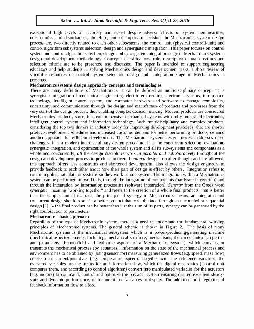
engineering graduates, is directly related to the applied structural design methodology. A guidelines for
structural design methodology and tools for the development process of Mechatronic products, that can
support educators and help students in solving Mechatronics design tasks with their specific properties
and can be applied in educational process is highly required, such guidelines for structural design
methodology are proposed in [1], this methodology is developed, based on VDI 2206 guideline and
different industrial, scientific and educational resources listed and some discussed in [1], and is proposed
to fulfill Mechatronics optimal program requirements. The proposed methodology consists of a
systematic specific simple and clear steps (depicted in diagram 1) that are easy to memorize, follow and
aims to support engineering educators and help non experienced student or group of students to integrate
gained multidisciplinary abilities and knowledge, in various stages in solving Mechatronics design
integrated tasks.
Mechatronics systems are supposed to be designed with synergy and integration toward constrains like
higher performance, speed, precision, efficiency, lower costs and functionality, and operate with
International Journal of Innovative Scientific & Engineering
Technologies Research 4(1):1-23, Jan-Mar. 2016
© SEAHI PUBLICATIONS, 2016 www.seahipaj.org ISSN: 2360-896X
2
exceptional high levels of accuracy and speed despite adverse effects of system nonlinearities,
uncertainties and disturbances, therefore, one of important decisions in Mechatronics system design
process are, two directly related to each other subsystems; the control unit (physical controll-unit) and
control algorithm subsystems selection, design and synergisteic integration. This paper focuses on control
system and control algorithm selection, design and synergisteic integration stage in Mechatronics systems
design and development methodology. Concepts, classifications, role, description of main features and
selection criteria are to be presented and discussed. The paper is intended to support engineering
educators and help students in solving Mechatronics design and development tasks. a short review of
scientific resources on control system selection, design and integration stage in Mechatronics is
presented.
Mechatronics systems design approach- concepts and terminologies
There are many definitions of Mechatronics, it can be defined as multidisciplinary concept, it is
synergistic integration of mechanical engineering, electric engineering, electronic systems, information
technology, intelligent control system, and computer hardware and software to manage complexity,
uncertainty, and communication through the design and manufacture of products and processes from the
very start of the design process, thus enabling complex decision making. Modern products are considered
Mechatronics products, since, it is comprehensive mechanical systems with fully integrated electronics,
intelligent control system and information technology. Such multidisciplinary and complex products,
considering the top two drivers in industry today for improving development processes, that are shorter
product-development schedules and increased customer demand for better performing products, demand
another approach for efficient development. The Mechatronic system design process addresses these
challenges, it is a modern interdisciplinary design procedure, it is the concurrent selection, evaluation,
synergetic integration, and optimization of the whole system and all its sub-systems and components as a
whole and concurrently, all the design disciplines work in parallel and collaboratively throughout the
design and development process to produce an overall optimal design– no after-thought add-ons allowed,
this approach offers less constrains and shortened development, also allows the design engineers to
provide feedback to each other about how their part of design is effect by others. Integration refers to
combining disparate data or systems so they work as one system. The integration within a Mechatronics
system can be performed in two kinds, through the integration of components (hardware integration) and
through the integration by information processing (software integration). Synergy from the Greek word
synergeia meaning "working together“ and refers to the creation of a whole final products that is better
than the simple sum of its parts, the principle of synergy in Mechatronics means, an integrated and
concurrent design should result in a better product than one obtained through an uncoupled or sequential
design [1]. ]- the final product can be better than just the sum of its parts, synergy can be generated by the
right combination of parameters
Mechatronic – basic approach
Regardless of the type of Mechatronic system, there is a need to understand the fundamental working
principles of Mechatronic systems. The general scheme is shown in Figure 2. The basis of many
Mechatronic systems is the mechanical subsystem which is a power-producing/generating machine
(mechanical aspects/elements, including; mechanical structure, mechanisms, their mechanical properties
and parameters, thermo-fluid and hydraulic aspects of a Mechatronics system), which converts or
transmits the mechanical process (by actuators). Information on the state of the mechanical process and
environment has to be obtained by (using sensor for) measuring generalized flows (e.g. speed, mass flow)
or electrical current/potentials (e.g. temperature, speed). Together with the reference variables, the
measured variables are the inputs for an information flow, which the digital electronics (Control unit
compares them, and according to control algorithm) convert into manipulated variables for the actuators
(e.g. motors) to command, control and optimize the physical system ensuring desired excellent steady-
state and dynamic performance, or for monitored variables to display. The addition and integration of
feedback information flow to a feed.
Salem …. Int. J. Inno. Scientific & Eng. Tech. Res. 4(1):1-23, 2016
Ok
3
Pre-Study Process (The problem statement ) :(It is the process of understanding what the problem is, its goals and functions , and to state it in clear
terms. Done by identification, gathering and analysis as much as possible information about) :
Aesthetics: if pleasing elegant design is required, color, shape, form and texture to be specified
The problem statement in clear terms : based on up steps, description of what is the problem? the goal? the top-level functions, and/or state the problem in terms of the deficiency that must be ameliorated user and system requirements,
b
1
Conceptual Design, functional specifications and their structure.
(Consider the system as a whole, building a description of it in terms of an interdisciplinary set of integrated general ideas and concepts, conceptual design is usually evolve from problem statement; user and system requirements)
2
Identification, description and analysis of the required system ,what is the system?, it's overall function? ,
sub-functions?, behavior/performance?, how it looks like?. a
Morphological analysis; Build Morphological table, suggest solutions for functions, evaluate the best solution. b
c
Parallel (concurrent) selection, evaluation, synergetic integration and optimization of the system and all its
sub-systems as a whole and concurrently, all the design disciplines work in parallel and collaboratively
throughout the design and development process to produce an overall optimal design– no after-thought
add-ons allowed. 3
Parallel (concurrent) optimal selection, evaluation, synergetic integration and optimization of the system
and all its modules-sub-systems and all components as a whole and concurrently throughout the design
and development process, with respect to the realization of the design specifications and requirements
Mechanical sub-system; the design of all mechanical aspects in full details to meet the requirements; structure Eements, Mechanisms, Dimensions, Materials, Properties, Parameters ...(CAD/CAM tools ....)
Electric & Electronics; Interconnections, signal conditioning, interfacing.
Divided the system into realizable modules ( subsystems).a
Sensors subsystem Actuators subsystemControl unit sub-system Control algorithm and design
Human–machine interaction field
Develop system's complete and detailed block diagram layout
Modeling, simulation ,analysis and evaluating:
The main goal; early identifying system level problems (to verify main and sub-functions and to test and analyze sub-systems and the whole system model), and ensuring that all design requirements are met (satisfied)
4
Two types of modeling process ; Analytical modeling; Represent the sub-systems and whole system
using mathematical equations suitable for computer simulation ( e.g. MATLAB, Labviev). Physical
(Experimental ) modeling; based on obtained measurements from the system
b
b
c
Prototyping, testing, evaluation and optimization
To take into account the unmodeled errors and enhance precision, performance and gather early user feedback5
Virtual Prototype: 2-3D model of a product presented in a virtual (PC) environment with, ideally, all
information and properties included, used to examine, manipulate, and test the form, fit, motion, logistics,
and human factors of conceptual designs on a computer monitor,
a
Physical Prototype: system integration to ensure that subsystems, components and whole system work
together under operating condition
Manufacturing and Commercialization6 Support, Service and Market feedback Analysis 7
simul
tane
ous s
yner
gisti
c in
tegr
atio
n an
d op
timiza
tion
of th
e sys
tem
and
all
its su
bsys
tem
s as a
who
le, n
o af
ter-t
houg
ht a
dd-o
ns a
llow
ed--
Itera
te fo
rwar
d an
d ba
ckw
ard
to fu
lfill
requ
irem
ents
Target user, market and user interests/needs/requirements identification and analysis; (build user
requirements table)
Build requirements analysis table; fixed and soft requirements, description and types
Create detailed functional specifications.
Built system functional model (function box, Sequence or Hierarchy ), depicting the flow of (information,
Energy or Material) between the system’s components
Build preliminarysystem block diagram and layout of main components.
Identify system’s preliminary necessary structure ( e.g. mechanical, electric, control….),
A preliminary economic analysis;feasibility study , cost-benefit evaluation d
Designing system as a whole, serve as methodological basis for Mechatronic Systems development
Prototype development may be carried out in the following two forms
Integration refers to combining disparate data or systems so they work as one system. The integration
can be performed in two kinds: The integration of components (hardware integration), results fromdesigning the mechatronics system as an overall system and embedding (placement ) the sensors,actuators, and microcomputers into the mechanical process. The integration by information processing
(software integration) is based on advanced control function
d
A preliminary ideas about mechanical, electric problems and the necessary sensors, actuators, interfaces.
Synergy can be generated by the right combination /selection of proper parameters that is, the final
product can be better than just the sum of its parts.c
a
Break down the overall function/system into subfunction/subsystems; what are major subsystems/components? what
are subsystem’s/components' functions? how components interact ?and how they should be connected?
Generate preliminary decisions about the dominant mechanical properties, (e.g. matrials, sizing, volume,
DOF, joints types)
Subsystems models; in open and closed loop
aModeling process ; Verifying sub-functions and testing sub-systems, consists of two levels:
Overall system model; the verified sub-functions and tested sub-systems are integrated in one overall
system model interacting similar to real situation is checked
Simulation process ; is used to decide on the design specifications of the mechatronic system in terms of
specification of requirements. simulation divided into three parts: Mechanical simulation; To test the
kinematics and dynamics variables. System simulation; To test the system’s response to different inputs
in both open and closed loop. Electronic simulation; To test circuits functionality and compatibility
System requirements/specifications identification, definition and analysis; functional, Performance
and environmental and non-functional requirements.
Figure 1 Systematic guideline steps for Mechatronics systems design education-oriented methodology
Salem …. Int. J. Inno. Scientific & Eng. Tech. Res. 4(1):1-23, 2016
Ok

4
forward energy flow in the mechanical system (e.g. motor drive, drainage pump) is one of the
characteristics of many Mechatronic systems. Interactions of man and machine have been profoundly
enhanced by the development of electronics and IT technologies (e.g. SMS, voice control) and
interactions have become more versatile and user-friendly [2-4].
Mechanical
system
Control
systemActuator
Electro-
mechanicalElectrical
system
D/A
A/D
Interfacing
Sensor
Humane machine
interface
Reference variable
Energy supply
Auxiliary Energy
supply (to actuator)
Figure 2(a)
Control unit /
Algorithm
(PLC,
Microcontroller,
Microcomputer
…
ON/OFF, PID,
Ladder program..
Input signal
conditioning &
interfacing
(ADC, MOSFET,
amplifier, Relay,
Voltage div….)
Output signal
conditioning &
interfacing:
(DAC, filters,
(H-bridge,
Relay, PWM…...)
Sensor/input
subsystemActuator/output
subsystem
Humane machine
interface
(Mechanical
system: structure, mechanisms,parameters, thermo-fluid/
hydraulic aspects)
Energy supply
Auxiliary Energy
supply (to actuator)
Reference variable
Measured variable
Manipulated
variable
Figure 2(b)
Figure 2(a)(b) Working principle and main subsystems of Mechatronic products
Control Unit/Algorithm Selection, Design and Integration in Mechatronics Design
Control stage components
During the cuncurrent design of Mechatronic systems, it is important that changes in the mechanical
structure and other subsystems be evaluated simultaneously; a badly designed mechanical system will
never be able to give a good performance by adding a sophisticated control system, therefore,
Mechatronic systems design requires that a mechanical system, dynamics and its control system structure
be designed as an integrated system (this desired that (sub-)models be reusable), modeled and simulated
to obtain unified model of both, that will simplify the analysis, prediction of whole system effects,
performance, and generally to achieve a better performance, a more flexible system, or just reduce the
cost of the system[2].One of most important decisions in Mechatronics design process are, two directly
related to each other subsystems; the control unit (physical controller) and control algorithm subsystems
selection, design and synergitic integration. As shown in Figure 3, three components can be identified at
this level; the control system, control algorithm and the electronic unit subsystems. The physical-
controller subsystem, can be structured, basically, around six basic forms (options) of programmable
Salem …. Int. J. Inno. Scientific & Eng. Tech. Res. 4(1):1-23, 2016
Ok

5
control system: Personal computer (PC), Microcomputer, Microcontroller (Mc), Digital signal processors
(DSP), Application specific integrated circuits (ASICs) and Programmable logic controller (PLC)[1].
also, there are a variety of control algorithms exits, including: ON-OFF, PID modes, feedforward,
adaptive, intelligent (Fuzzy logic, Neural network , Expert Systems and Genetic) control algorithms. The
key factors that might influence the decision on selecting certain control unit/algorithm include; a)
Operation (how system will run and how tasks/ instructions are processed), b) Robustness/environment
(e.g. industrial, soft.. ), c) Serviceability (availability of replacement components and ease of repair/
replacement over controller life), d) Security (e.g. viruses), e) programming: Both programming
environment (how control executes program) and language (e.g. C++) affect machine development time
and operation f) unit cost, cost of final product, precision, required time to market, g) size-space saving, h)
integration, i) processing power, also, safety criticality of the application, and number of products to be
produced [1][6].
In Mechatronics system design, the selection of control unit, control algorithm, sensors and actuators is
followed by selecting and integrating the electronic unit subsystem; in particular, Interconnection, signal
conditioning, and interfacing e.g. power supplies, drives circuits, signal processing-conditioning circuits
and data acquisition systems. As shown in Figure 4 these are selected to interface the whole system
components and match components specifications and ratings in and to optimize the system performance.
Since most measurement and control apparatus are of an analog nature, while control units are digital, to
enable the control unit to communicate with the outside analog world, interface hardware allows
analog/digital interfacing, communication of sensor signal to control unit and communication of control
signal from the control unit to the actuator.. The electronic unit has to adjust the control signals output by
the control unit and by the sensor subsystem to the level required by the actuator subsystem, in order to be
useful to the control unit. Sometimes, this unit can fulfill additional tasks: system protection, display and
setting of some functional parameters etc. The electronic unit can contain: a) basic electronic
components: resistors, potentiometers, condensers, rectifier diodes, stabilizers, transistors etc. b) linear
integrated circuits based on operational amplifiers: ramp generators, step generators, adders, PID
regulators, Dither generators, current generators, oscillators, demodulators etc. c) supply units; A/D and
D/A convertors[7].
PC
Mechatronics system design approach
( The concurrent, selection , synergistic integration and optimization of the whole system and all its subsystems as a whole and concurrently,
including ; Mechanical, sensors, actuators, electric, electronics control)
Control stage
Control system
(Unit) subsystem
Electronic s unit
subsystem
Concurrency Integration
Programmable Control system
Control algorithm
subsystem
Microcomputer
Microcontroller
DSP
ASICs
ON-OFF
PID-modes
Feedforward
Adaptive
Intelligent
PLC
Fuzzy logic Neural network
Geneticalgorithm
Expert Systems
Synergy
Figure 3a Components at control stage; Control system/ algorithm electronic unit subsystems
Salem …. Int. J. Inno. Scientific & Eng. Tech. Res. 4(1):1-23, 2016
Ok

6
(a) (b) (c) (d)
Figure 3(b) (Physical) controller options; a) PLC, b)Microcontroller, c) Computer control, d) Analog
controllers.
Control unit /
Algorithm
(PLC,
Microcontroller,
Microcomputer
…
ON/OFF, PID,
Ladder program..
Input signal
conditioning &
interfacing
(ADC, MOSFET,
amplifier, Relay,
Voltage div….)
Output signal
conditioning &
interfacing:
(DAC, filters,
H-bridge, Relay,
PWM…...)
Figure 4 Interconnection, signal conditioning, and interfacing.
Control system strategies/algorithms selection and design There are many control strategies that may be more or less appropriate to a specific type of application,
each has its advantages and disadvantages; the designer must select the best one for specific application
[8-10]. Engineering practice usually dictates that one chooses the simplest controller that meets all the
design specifications. In most cases, the more complex a controller is, the more it costs, the less reliable it
is, and the more difficult it is to design. Choosing a specific controller for a specific application is often
based on the designer's past experience and sometimes intuition, and it entails as much art as it does
science [10] the choice of the controller type is an integral part of the overall controller design, taking into
account selection factors, and in particular, with final aim to obtain the best cost/benefit ratio and
therefore the simplest controller capable to obtain a satisfactory performance should be preferred [11].
Based on up mentioned, and on particular Mechatronics system purpose, destination, desired
performance, precision, efficiency, costs, functionality and complexity, the control unit and algorithm are
selected and designed.
The terms control system design can be referred to any of the following three forms; a) writing
corresponding control program/algorithm (e.g. for PLC, CNC or Microcontroller) to control the process,
or b) Developing a knowledge base, Inference mechanisms and communication interfaces for intellegent
control or, c) The process of selecting feedback gains (poles and zeros) that meet design specifications in
a closed-loop control system. Most design methods are iterative, combining parameter selection with
analysis, simulation, and insight into the dynamics of the plant [11-12]. Different control system design
approaches are available and can be applied to design and test the selected control algorithm [1]. In [13-
14] is presented simple and user friendly controllers and design guide that illustrates the basics of
controllers and control algorithms, their elements, effects, selection and design procedures.
3. Control system-units classification and description of main features
Automatic control applications are particularly well suited to take advantage of microcontroller/
microprosseeor technology. Microprocessor-based control systems are rapidly replacing many older
control systems based on analog circuits or electromechanical relays. One of the first microprocessor-
based controllers made specifically for control applications was the programmable logic controller (PLC)
Salem …. Int. J. Inno. Scientific & Eng. Tech. Res. 4(1):1-23, 2016
Ok

7
[15]. As noted, the physical-controller subsystem, can be structured, basically, around six basic forms of
programmable control system, those basically are computers which have four basic operational parts
depicted in Figure 5(a); Central processing unit (CPU), Programmable memory, and I/O peripherals. All
computers have a means of getting input, a means of generating output, a means of controlling the flow of
signals and operations, memory for data storage, and an arithmetic logic unit (ALU) which executes the
instructions. The ALU and control elements are often called the central processing unit (CPU). Small
computers, which just contain a CPU, are often called microprocessors (Figure 5(b)). Memory for these
computers is often attached to the microprocessor but in distinct electronic packages. Input and output to
the microprocessor is often handled by electronics called peripherals. If the memory is included in the
same package, the computer is called either a microcomputer or computer depending on its physical size.
CPU and memory on a single electronics chip is often called a microcomputer [16].
Arithmetic logic unit (ALU)
Control
Storage memory
CPU
Input Output
Figure 5(a) Main elements of a computer.
Microprocessor
Memory Input Output
Figure 5(b) Microprocessor and Microcontroller [15]
VARIABLES, PROCESSES AND CONTROLS There are two basic types of variables (and parameters) that characterize (production) operations;
continuous and discrete variables. Corresponding to these two types, there are two basic types of
production processes; continious and discrete, corresponding to this, there are two basic types of
industrial control; continuous and discrete control systems. Continuous control is used to control the
continuous variables in continues processes in processes industries (e.g. an oven temperature).
Continuous controllers automatically and continuously measure and compare the value of controlled
variables to the reference set-point to determine if an error exists, and take corresponding actions to alter
the processes. Discrete control is used widely in both discrete manufacturing, as well as, in the process
industries. Consequently many industrial controllers are designed with the capability to receive, operate
on, and transmit both types of signals and data (continuous and discrete). The metioned categorization are
depicted in Figure 12(a). Discrete control system executes their actions to change and alter the processes
in the following two cases: a) When discrete-state of the controlled process has changed, or b) when a
certain a mount of time has elapsed. According to these changes, we can distinguish two types of
processes: a) Discrete event – driven processes, and b) Time-driven-process. Also, we can distinguish
two types, executed by controller, changes to alter the process : a) Discrete event–driven executed
Salem …. Int. J. Inno. Scientific & Eng. Tech. Res. 4(1):1-23, 2016
Ok
8
changes: the controller execute the next step in the program to act on the processes , in response to the
occurrence of some discrete processes event, that change the state of the system, and b) Time-driven
executed changes: The execution of control changes occur, when a certain a mount of time has elapsed or
at a specific point in time. Corresponding to this, we can distinguish two types of discrete control: a)
Combinational logic control ( or logic control), and b) Sequential control. Logic control and sequencing
are referred as switching systems in the sense that they switch their output vales ON and OFF in response
in changes in events or time, whose output values at any time are, exclusively, determined from the
present combination of inputs. The basic elements of combinational logic control are the logic gates ( e.g.
AND, OR, NOT , NOR, NAND) and the use of ladder logic and Boolean algebra. Meanwhile, sequential
control, controls a process that is defined as a series-sequence of time/event-driven operations of tasks to
be performed, one after the other and the controller execute the next step in the program to act on the
processes , in response to the occurrence of some discrete processes event, that change the state of the
system. Examples of discrete processes: Manufacturing lines, elevators, traffic systems, Conveyors and
other material transport system, automated storage system, stand-alone production machines, all these
processes operate by following a defined sequence of performed operations (start and stop actions, on
and off ) [15].
Control loops (Sensor-Controller-Actuator) can be divided into two categories: a) Single variable single-
loop control, b) Multivariable multi-loop control. In practical control problems, there are a number of
process variables which must be controlled and a number of variables which can be manipulated.
Multivariable multi-loop control loop :are control loops in which a primary controller controls one
process variable by sending signals to a controller of different loop that impacts the process variable of
the primary loop.The common terms used for single loop control include: a) feedback control loop, b)
Feedforward control loop. Meanwhile, key terms of multiple control loops include; a) Feedback plus
Feedforward, b) Cascade control, c) Ratio control, d) override controls.
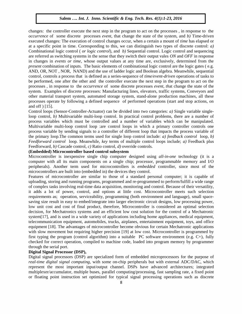
(Embedded) Microcontroller based control subsystem
Microcontroller is inexpensive single chip computer designed using all-in-one technology (it is a
computer with all its main components on a single chip; processor, programmable memory and I/O
peripherals). Another term used for microcontrollers is embedded controller, since most of the
microcontrollers are built into (embedded in) the devices they control.
Features of microcontroller are similar to those of a standard personal computer; it is capable of
uploading, storing and running programs, programmed and re-programmed to perform/fulfill a wide range
of complex tasks involving real-time data acquisition, monitoring and control. Because of their versatility,
it adds a lot of power, control, and options at little cost. Microcontroller meets such selection
requirements as; operation, serviceability, programming (both environment and language), small space-
saving size result in easy to embed/integrate into larger electronic circuit designs, low processing power,
low unit cost and cost of final product, therefore, Microcontroller is considered an optimal selection
decision, for Mechatronics systems and an efficient low cost solution for the control of a Mechatronic
system[17], and is used in a wide variety of applications including home appliances, medical equipment,
telecommunication equipment, automobiles, trucks, airplanes, entertainment equipment, toys, and office
equipment [18]. The advantages of microcontroller become obvious for certain Mechatronic applications
with slow movement but requiring higher precision [19] at low cost. Microcontroller is programmed by
first typing the program (control algorithm) into a suitable PC software environment (e.g. C+), fully
checked for correct operation, compiled to machine code, loaded into program memory by programmer
through the serial port.
Digital Signal Processor (DSP),
Digital signal processors (DSP) are specialized form of embedded microprocessors for the purpose of
real-time digital signal computing, with some on-chip peripherals but with external ADC/DAC, which
represent the most important input/output channel. DSPs have advanced architectures; integrated
multiplexer/accumulator, multiple buses, parallel computing/processing, fast sampling rate, a fixed point
or floating point instruction set optimized for typical signal processing operations such as discrete
Salem …. Int. J. Inno. Scientific & Eng. Tech. Res. 4(1):1-23, 2016
Ok

9
transformations, filtering, convolution, and coding all for the purpose of real-time digital signal
computing.
DSP is an optimal cotrol selection decision and preferred over microcontrollers, for application requiring
real-time DSP computing constrains ( implement complex and iterative algorithms and perform
computationally efficient and fast algorithms), like sound processing/generation, sensor (e.g., Vibration)
signal analysis telecommunications (e.g., bandpass filter and digital modulation/demodulation in mobile
phones, communication transceivers, modems), missile control and vector control of AC motors. [16]
[20-22].
Application specific integrated circuits (ASICs) Are custom made devices to perform a specific application/operation such as a PID algorithm, run a cell
phone, control the functions of the vehicle. ASICs can contain a CPU or memory or peripheral functions
or even a MAC cell as part of its makeup [16].
ASIC is an optimal selection decision, for Mechatronics systems designer who wish to define the function
of his own integrated circuit. The major incentive to design an ASIC for an application is its impact on the
overall cost, size and performance of a system, many functions can be integrated into single devices, and
therefore, the number of components and size circuit board can be reduced [23].
Computer based control subsystem
In Mechatronic systems, computers play a variety of roles; they model, analyze, and simulate
Mechatronic systems and components and are useful for control design. As part of measurement systems,
they are used to measure the performance of Mechatronic systems, to determine the value of component
parameters, and to validate models experimentally. Finally, they form the central component in digital
control systems for Mechatronic designs. Because most Mechatronic systems are analog (the sensor and
the final control element are analog devices), it must have both ADC and DAC converters, which serve as
translators that let the computer communicate with the outside analog world[24]. Personal computer
based control subsystem is not suitable for a large number of Mechatronics products and is limited by the
high costs and size involved. Advantages include superior signals processing, graphical capabilities, and
software flexibility.
Personal computer based control subsystem, are an optimal selection decision, for Mechatronics systems
in the case of very complex applications, and when extensive signal processing and in-depth analysis is
required, also in research activities, in laboratory conditions, e.g. when an experimental model has to be
tested. PC can be made suitable for industrial environment (discussed in 3.6 PLC), some models of these
computers are rack-mountable and contain their own battery-backup power supply.
There are two basic requirements that must be placed on the computer (and managed by controller) to
achieve real-time control requirements: a) Process-initiated interrupts; to respond to incoming signals
from the process, b) Timer-initiated actions: to executing certain actions at specific points in time. These
two basic requirements correspond to the two types of changes in discrete control, a) Event-driven
changes, b) Time-driven changes. In addition to these two basic requirements, the control computer must
also deal with other types of interruptions and events, these include: a) Computer command to process
actuators (able to send control signals to the process to accomplish a corrective action), b) System-and
program-initiated events: such as the printing or display of reports on a printer or monitor, c) operator-
initiated events: entering new programs, editing existing program, entering customer data, order or
number, or startup instructions for the next production run, Emergency stop.
If the control system is configured around a PC, one of the following versions can be chosen: a)
Computer-Aided Data Acquisition consisting of; PC , data acquisition board (DAC) and software. b)
PC, I/O modules and software, an example temperature, computer based control system, of an eclectic
furnace, is shown in Figure 6, the temperature in electric furnace is measured by analog thermometer, the
analog temperature is converted to digital temperature by ADC converter, the digital temperature is fed to
controller (Computer) through an interface, this digital temperature is compared with the programmed
input temperature, and if there is an error, the controller, according to written control algorithm program,
Salem …. Int. J. Inno. Scientific & Eng. Tech. Res. 4(1):1-23, 2016
Ok

10
sends out control signal to control the actuator (Heater) , through an interface, amplifier, and relay, to
bring the furnace temperature to desired value[25].
A generation refers to the state of improvement in the development of a product. This term is also used
in the different advancements of computer technology, with each new generation, the circuitry has gotten
smaller and more advanced than the previous generation before it. As a result of
the miniaturization, speed, power, and memory of computers. The development of the computer, and then
the microcomputer, led to embedded computers/ Microcomputers. Microcomputers can be integrated with
the actuator/sensors, this integration lead to smart sensors and smart actuators. Embedded
microcomputers are hidden in products such as machines, vehicles, measuring instruments,
telecommunication devices, home appliances, consumer electronic products (cameras, hi-fi systems,
televisions, video recorders, mobile phones, music instruments, toys, air-conditioning). They are
connected with sensors, user interfaces (buttons and displays), and actuators[1][26]
Relay Amplifier PC Interface
PC Interface ADC
converter
Power
Thermocouple
Furnace Inputs
Figure 6 an example of temperature, computer based control system, of an eclectic furnace [25].
Programmable logic controller (PLC), based control subsystem
PLC is form of programmable automation, it can be defined as a microcomputer based controller that use
control program instructions stored on its programmable memory to implement logic, sequencing, timing,
counting and arithmetic functions through digital or analog input/output devices, it purpose to sense,
activate and control industrial equipments, machine and process, and to operate in an unfriendly
industrial environment. Therefore, PLC is an optimal efficient selection decision, for controlling
industrial Mechatronics systems. Advantages of PLC include: designed for hursh industrial environment,
programming is very user friendly (using ladder diagrams, instructions or function blocks), can be
programmed to carry out arithmetic operations and control tasks e.g PID control algorithm, be re-
programmed, can be connected to computer system-network, or with human interfaces, low price (PLC
prices going down), size shrinking, and performance of PLCs improving over the years, have integrated
diagnostics, can display process state, signal failures and override functions, applications can be
immediately documented.
Differences between computer and PLC, include :a) PLC has the advantage of being designed for the
harsh environment of factory, while PC was designed for office environment. b) PLC with its built-in
input and output interface could be readily connected to external equipments, whereas the PC requires
special input and output cards to enable such connections. c) In PLC, there is much more proprietarily
software and architecture than in PC. d)Advances had mad PC speeds doubling every 18 months which is
much more rapidly than PLC technology. PC can be made suitable for industrial environment, where
numerous manufacturers are selling rugged PCs that can survive in harsh industrial environments: a) PC
can be equipped with membrane-type key-boards for protection against factory moisture, oil, and dirt.. b)
PC can be ordered (customised) to come with have sealed cases and filters covering the air vents, also,
with input and output cards and related hardware, to provide the necessary devices to connect the
industrial equipment's and processes[15].
Salem …. Int. J. Inno. Scientific & Eng. Tech. Res. 4(1):1-23, 2016
Ok

11
Digital Communications
Intercommunication among Mechatronics subsystems plays a key role in their engagement of
applications, both of fixed and flexible configurations. Digital communication depends on the designer's
demands for the amount of transferred data, the distance between the systems, and the requirements on
the degree of data reliability and security. The signal is represented by alterations of amplitude,
frequency, or phase. This is accomplished by changes in voltage/current in metallic wires or by
electromagnetic waves, both in radio-transmission and infrared optical transmission [16][22]
CONTROL ALGORITHMS; ROLE AND DESCRIPTION OF MAIN FEATURES
Different types of control algorithms are available for Mechatronics system control, including; ON-OFF,
PID modes, feedforward, adaptive, intelligent (Fuzzy logic, Neural network , Expert Systems and
Genetic) control algorithms [1].
ON-OFF control algorithm
Also called Discrete (or bang-bang) controller. It is the simplest of all control algorithms and are ones
that, in response to input error, have only two output modes (positions); fully OFF or fully ON ( a third
output may be; No change). It requires actuators (final control elements) that have two corresponding
command positions: on/off (open-closed). The main purpose, of this algorithm, is to keep a given physical
variable within certain limits or to change it according to a predetermined program. Home heating
thermostat is an ideal examples of mechanical on/off controller.
Advantages of ON-OFF control algorithm include; a) simple, requires basic types of
instruments/components, b) easy to troubleshoot, d) low cost. Disadvanteges include; a) no fixed
operating, the controlled process oscillates, becouse control doesn’t hold the variable at setpoint, but
keeps the variable within proximity of setpoint, b) excessive wear of final control element, since it is
always opening and closing.
ON-OFF control algorithm is optimal selection decision, for slow acting operations not requiring high
accuracy; such as industrial automation applications, refrigeration unit, home water heater, and
applications like smart home, microwave, washing machine.
Proportional-Integral-Derivative (PID) control algorithm modes.
PID control algorithm is combinations of three control algorithms; Proportional (P), Integral (I), and
Derivative (D) algorithms. The modes of PID control algorithm are combination of these thee algorithms:
P-, PI- ,PD-, PID -, lag, lead or lag-lead algorithm, where the last three are soft approximation, PI,PD and
PID modes respectively.The input to PID algorthims is the error between actual and setpoit values, if
there is an error, the controller adjusts its output according to P-, I-, or D- parameters (gains) that have to
be set in the algorithm, where, as noted, the term control system design refers to the process of selecting
feedback algorithm parameters (gains) that meet desired design specifications in a closed-loop control
system.
Role/effect of each tuning parameter (gain) on system's response, include: a) P-algorithm; is proportional
to error,it is the simpliest and determines how much correction should be made, speeds up response and
reduces, but never eliminates steady state error. b) I-algorithm; inegrates error and determines how long
should the correction be applied, slows the response times and reduce/eliminates steady-state error. d) D-
algorithm; deffirentiates error and determines how fast should the correction be applied, acts only in the
transient response, speeds up response and reducs overshoot. In [13-14] is presented simple and user
friendly controllers and design guide that illustrates the basics of controllers and control algorithms, their
elements, effects, selection and design procedures. the following simplified guide for PID control
algorithm selection, can be suggested; (1) for processes that can operate with continuous cycling, the
relatively inexpensive two position controller is adequate.(2) For processes that cannot tolerate
continuous cycling, a P-controller is often employed. (3) For processes that can tolerate neither
continuous cycling nor offset error, a PI controller can be used. (4) For processes that need improved
stability and can tolerate an offset error, a PD-controller is employed. (5) However, there are some
Salem …. Int. J. Inno. Scientific & Eng. Tech. Res. 4(1):1-23, 2016
Ok

12
processes that cannot tolerate offset error, yet need good stability, the logical solution is to use a control
mode that combines the advantages of the three controllers' action [13][27]
PID algorithms provides an optimal solution to both reference tracking and disturbances rejection, also,
due to it's simplicty, ease of design, moderate cost, PID control algorithms are an assential part of the
control loop of many applications in manufaturing industies and process industries.
Control system configurations selection Most of the conventional selection and design methods in control systems rely on the so-called fixed-
configuration design in that the designer at the outset decides the basic configuration of the overall
designed system and decides where the controller is to be positioned relative to the controlled process?.
The five commonly used system configurations with controller compensation, are ( see Figure 7)
(1)Series (cascade) compensation; it is the most common control system topology, were the controller
placed in series with the controlled process(plant), with cascade compensation the error signal is found,
and the control signal is developed entirely from the error signal. (2)Feedback compensation, the
controller is placed in the minor inner feedback path in parallel with the controlled process. (3) State-
feedback compensation the system generates the control signal by feeding back the state variables through
constant real gains. (4)Series-feedback compensation a series controller and a feedback controller are used
(5) Feedforward compensation: the controller is placed in series with the closed-loop system, which has a
controller in the forward path the Feedforward controller is placed in parallel with the forward path[13]
system to be controlled
G(s)
Reference
Input command
R(s)
Controlled
variable
C(s)+
-
Primary feedback B(s)
controller
ERROR
E(s)The actuating signal
U(s)
Feedback element
Sensor /Transducer
H(s)
Disturbances
D(s)
Input , R(s) Output , C(s) Compensator
H(s)
G(s)
Fixed PlantDesignable controller
Figure 1 (a) Figure 1 (b)
Figure 7(a) series or cascade compensation and Components
Input , R(s) Output , C(s) G(s)
Fixed Plant
Compensator
Designable controller
GP(s)
y(t)u(t)
+ -
x(t)
K
Feedback
Cr(t)
Figure7(c) Feedback compensation Figure 7(d) State feedback
E(t)u(t)
G(s)r(t)
++-
-
y(t)Gc(s)
GH(s)
y(t)r(t) e(t)
+-
u(t)PlantGf (s) Gc (s)
Figure 7(e) Series-Feedback compensation
(2DOF)
Figure 7(f) forward with series
compensations
r(t) y(t)+
-Plant
Gf (s)
Gc (s) +
u(t)
Figure 7(f) Forward compensations
Salem …. Int. J. Inno. Scientific & Eng. Tech. Res. 4(1):1-23, 2016
Ok

13
Feedforward (Feedforward/ feedback) control algorithm.
The main disadvantage of feedback control loop, is that the controlled variable must leave setpoint, (an
error must occur) for control action to be taken to return the controlled variable to desired setpoint, that is
the disturbance must propagate through the entire process, before the feedback control can initiate action
or compensation[28]. Feedforward control algorithm, addresses this weakness, it compensates for
measured disturbances, it monitors (predicts and measures) all factors (important disturbance variables)
influencing a process, as it enters the process, decides how to compensate for these factors and takes
corrective action (how quickly and directly to cancel out the effect of a disturbance) a head of time before
factors effect the controlled process. Therefor, the error is prevented, rather than correct.
Because of the difficulty of accounting (and anticipating) for every disturbance factor influencing a
process and to decide how to compensate for each factor a head, feedforward are often combined with
feedback algorithm(shown in Figure 8), where a feedback algorithm is required to track setpoint changes
and to resject the effect of unmeasured disturbances upon the controlled variables. Feedforward algorithm
is optimal selection decision when the system stability and disturbance rejection are crucial, and only a
small error is allowed.
Feed forward controller
Disturbance sensor
Disturbance
Feedbackcontroller
Actuator
Sensor
E(s)C(s)
Plant+-
FF action
Figure 8 Block diagram of feedforwar-feedback control algorithm
Adaptive control algorithm
To ''adapt" means to change a behavior to conform to new circumstances[29]. An adaptive controller is a
controller that can modify its behavior in response to changes in the dynamics of the process and the
character of the disturbances. Adaptive control algorithm covers a set of techniques which provide a
systematic approach for automatic adjustment of controllers in real time, in order to achieve or to
maintain a desired level of control system performance when the parameters of the plant dynamic model
are unknown and/or change in time.
As shown in Figure 9, Adaptive control systems consist of two loops; an ordinary feedback loop and a
second loop which adjusts parameters of the feedback loop. The parameter adjustment loop comprises
two main modular elements. One module performs operations to estimate the parameters of the model
governing the plant process. Based on this knowledge, the second module computes the value of control
parameters for the regulator. Both parameter estimation and control adaptation can be done in many
different ways. Recursive least-squares estimation is one of the most commonly used estimation
technique [6]. Different adaptive control algorithms exist, including feedback adaptive and feedforward
adaptive. Adaptive control algorithm is optimal selection decision for dynamic systems operating in
unstable environments, ranging from aircraft to medical robots.
Salem …. Int. J. Inno. Scientific & Eng. Tech. Res. 4(1):1-23, 2016
Ok

14
Actuator
Sensor
E(s)C(s)
Plant+-
R(s) Feedbackcontroller
Controller design ; (estimating controller
parameters)
System identification; (estimating plant parameters)
Adaptive control
Parameters
adjustment
Figure 9 Adaptive control algorithm
Intelligent control algorithms
The fact is that there are problems of control which cannot be formulated and studied in the conventional
differential/difference equation mathematical framework. To address these problems in a systematic way,
a number of methods have been developed that are collectively known as intelligent control
methodologies [30]. Intelligent control algorithms include, but not limited to; Fuzzy logic, Neural
network, Expert Systems, Genetic, Bayesian and Neuro- Fuzzy algorithms.
Various definitions of intelligent control systems do exist, can be found in [31-33]. Intelligent control
algorithms can be defined as: a class of control algorithm techniques offer alternatives to conventional
approaches, by the use of various artificial intelligent (AI) computing approaches to develope systems
that display aspects of intelligent behaviour and designed to imitate the human capabilities of thinking,
sensing and decision-making. An intelligent system can be built up, with the ability “to model, reason and
learn the process and its automatic functions within a given frame and to govern it towards a certain
goal”.
Intelligent control comprises: a) multi-control (executive) functions, b) a knowledge base ; contains
quantitative and qualitative knowledge, c) Inference mechanisms; draws conclusions either by
quantitative reasoning (e.g., Boolean methods) or by qualitative reasoning (e.g., possibilistic methods)
and takes decisions for the executive functions, d) and communication interfaces [34].
Intelligent control algorithm is optimal selection decision, when understanding of the plant or its internal
dynamics are unknown, ( no accurate plant's model or plant is too complex to be modeled) , also for
plants with uncertain and varying operational conditions and environment, to result in improved
efficiency, effectiveness and performance, disadvantages of intelligent control algorithms include; In
some cases controller structures require the model of the plant, which may be is complex /uncertain and
tedious to get., the design of controller requires understanding (experience) the system and to know the
relationships between the input-output .
Fuzzy logic control algorithm
Fuzzy control is a practical alternative methodology to represent, manipulate and implement a smart
human’s heuristic knowledge about how to control a system [35]; it provides a convenient method for
constructing nonlinear controllers via the use of a human’s heuristic knowledge, where it integrates
human’s heuristic knowledge (thinking, understanding, sensing, decision-making and experience) of
skilled operators and/or control engineer, then express it using a natural description language (descriptive
model), as rules on how to control the process and achieve high-performance control, these rules are
incorporated into a fuzzy controller that emulates the decision-making process of the human. Fuzzy
control structure is shown in Figure 10,
The structure of the fuzzy controller largely depends on the input and output classifications. Fuzzy logic
algorithm can be expanded to fuzzy-PD, fuzzy-PI, fuzzy-adaptive algorithms, where for example as
Salem …. Int. J. Inno. Scientific & Eng. Tech. Res. 4(1):1-23, 2016
Ok

15
shown in Figure 10(b), fuzzy algorithm is applied to assign the correct values of PID/PD/PI parameters
based on the state of error and derivative/integral of error. Fuzzy control algorithm is optimal selection
decision, when the internal dynamics of the plant are unknown, too complex real-world systems (no
accurate plant model - difficult to model and simulate). Fuzzy control (as an intelligence control
algorithm) is select for controlling complex system difficult to model, and is accomplished through
system experienced based understanding. also, because of the simplicity of design and implementation,
and thus significantly reduces the time required to develop the entire system[6]. Disadvantages of fuzzy
control include that fuzzy controllers with fixed structures fail to stabilize the plant under wide variations
of the operating condition.
Rule Knowledge base
Inference mechanism
Fuzz
ific
atio
n
DeF
uzzi
fica
tion
Output
Input(1)
Input(2)
Figure 10(a)
PID modesR(s)
Rule Knowledge base
Inference mechanism
Fuzz
ific
atio
n
DeF
uzz
ific
atio
n
Output
Input(1)
Input(2)
Plant
Sensor
E(s) C(s)
Fuzzy PID modes-gains scheduling
Figure 10(b) example of fuzzy logic algorithm expansion to fuzzy-PD, fuzzy-PI, fuzzy-adaptive
algorithms 4.7 Expert control algorithm.
Also called knowledge-based control system, conceptually similar to fuzzy control algorithm, and can be
defined as an artificial intelligence based system which can convert the knowledge and experience of an
expert, to emulate the reasoning procedures of a human expert in order to generate the necessary control
action. Expert systems can learn, gain new knowledge, and improve their performance through
experience.
Expert systems are software programs, supplemented by man-machine interfaces, which use knowledge
and symbolic reasoning to perform complex tasks at a performance level usually achieved by human
experts. The Expert system is composed of ordinary estimation and control algorithms which are
combined with a knowledge-based system that captures the heuristics concerning the design and
operational practice [36].
Salem …. Int. J. Inno. Scientific & Eng. Tech. Res. 4(1):1-23, 2016
Ok

16
4.8 Neural Networks algorithm
Also more appropriately called ''Artificial Neural Network, ANN'' , and are used to estimate or
approximate, to capture and represen, functions that can depend on a large number of inputs and are
generally unknown. Neural networks based control system performs a specific form of adaptive control. It
is represented as a nonlinear map between the inputs and outputs which represent the dynamic behavior of
the system, this map forms a network that can be trained to implement any kind of control strategy. The
challenge in using ANN for feedback control purposes is to select a suitable control system structure, and
then to demonstrate using mathematically acceptable techniques how the ANN weights can be tuned so
that closed-loop stability and performance are guaranteed [37].
ANN are modeled based on the structure of biological nervous systems, where the brain of all the
advanced living creatures (Humans and other animals) process information with neural networks, which
consists of neurons (a basic nerve cells). The sole purpose of a Neuron is to receive electrical signals,
accumulate them and see further if they are strong enough to pass forward. Artificial Neural Network is
shown in Figure 11. The circles in the image represents neurons. The network is called multilayered
because it consists of more than two layers,(The neurons are arranged in a number of layers), generally
three; a) input (is passive meaning they do not modify the data, they receive a numeric single value on
their input, and duplicate/ pass the value to to the next level), b) hidden/middle; is active meaning it
modify the numeric input, does some calculations and forwards to the next layer, the number of neurons
in this layer is crucial. There is no formula for calculating the number, the values entering a hidden node
are multiplied by weights, a set of predetermined numbers stored in the program. The weight associated
with a dendrites basically determines the importance of incoming value. A weight with larger value
determines that the value from that particular neuron is of higher significance. The weighted inputs are
then added to produce a single number. Before leaving the node, this number is passed through a
nonlinear mathematical function called a sigmoid. This is an "s" shaped curve that limits the node's
output. That is, the input to the sigmoid is a value between -∞ and +∞, while its output can only be
between 0 and 1. c) output layers (active, consists of neurons which does alculations and gives the final
result output). [38-39]
Figure 11 Artificial Neural Network
5. CONTROL IN MECHATRONICS OF PRODUCTION SYSTEM (MECHATRONICS
AUTOMATION TECHNOLOGY) [15][40-42]
Production, Manufacturing and Automation
Industry can be defined as: any type of economic activity producing or supplying goods or services, it is
part of a chain from raw materials to finished product, finished product to service sector, and service
sector to research and development. Industry varies over time and between different countries. As shown
in Figure 12(a),industry can be calssified into, four categories: Primary, Secondary, Tertiary and
Quaternary industries.
Automation is derived from Greek word automatos: Auto 'self 'and Matos 'moving or acting' means self
dictated or self acting. automation can be applied in different fields resulting in such fields as Home
Salem …. Int. J. Inno. Scientific & Eng. Tech. Res. 4(1):1-23, 2016
Ok
17
automation, library automation, industrial automation. In the concepts of automation and production, If
there is industry present, chances are good that there is automation present. An automation system is a
precisely planned change in a physical or administrative task (e.g. manufacturing or data-processing)
utilizing a new process, method, or machine that increases productivity, quality, and profit while
providing methodological control and analysis. The value of system automation is in its ability to improve
efficiency; reduce wasted resources associated with rejects or errors; increase consistency, quality, and
customer satisfaction; and maximize profit. Manufacturing Automation can be defined as the process of
having the machines follow a predetermined sequence of operations with little or no human labor using
specialized equipment and devices that perform and control manufacturing process by applying advances
in technology to all types of enterprise’s (factory) production system operations. Automated
manufacturing systems (AMSs), are combination of mechanical design/mechanics, automation, drive
technology, sensors, saftey teachnoloy and others. AMSs operate in the factory on the physical product,
which perform operations such as: processing, assembly, inspection, Material handling. It is called
automated because they perform operation with reduced human participation compared to manual
process/system.
Production means all the stages and processes of producing a product, including market studying and
analyzing, product designing, design for manufacturing, and manufacturing processing stages, packaging,
distribution. (information and processing stages). Manufacturing : the word manufacturing is derived
from the Latin word manu factus (manu = hand, factus = made), which mean mad by hand, it is the
process of converting (changing the shape, physical properties or appearance) of raw materials to create a
final product. Production system is a dynamic network (it is the collection) of people, , principles,
methods, procedures, tools , equipments (material handling, inspection and testing equipments),
Production machines and workstations and computer system to coordinate and control, all these
components are organized for planning, manufacturing and for continuous improvement of business
processes. Production system can be clissified into, a) manufacturing system facilities(come in direct
physically contact with the parts (touch the product) and/or assemblies the product being made, and
include; people, machines, equipments, computer), b) The manufacturing support systems include;
Market analysis, Product design, Design for Manufacture and manufacturing planning, that do not contact
the product, but they plan and control the product’s progress through the factory and insuring that the
products meets quality standards.
Automation of the production system corresponding to the production system classification, and classified
into; , a) Automation of manufacturing system ; It is the process of automating the physical operations
sequence on the product, such as processing using machine tools, assembly machines, inspection or
material handling using specialized equipment and devices that perform and control manufacturing
process, e.g. Computer numerically controlled machines (CNC), Automated Production Machines using
PLC, Automation of Tool changing ,Automated Storage and Retrieval Systems and Automated
Warehousing , all using PLC, b) Computerization of manufacturing the support system; Using the
computer systems to accomplish the information processing activities that providing the data and
knowledge required to successfully produce the product ( CAD (computer systems that allow to sit and
create the drawings on the computer screen instead of on a paper), CAM ( linking of computer files
directly from the CAD system to the shop floor) , CAD/CAM, and also CIM (Computer integrated
manufacturing is the integration of the total manufacturing enterprise involves the integration of different
manufacturing systems, and involves communication between robots, sensors, CNC machinery, and other
types of devices that perform manufacturing operation) .
As shown in Figure 12(a), Automation system can be classified based on the flexibility and level of
integration in manufacturing process operations into; a) Hard (or fixed) automation; It is an automation
system in which sequence of processing (or assembly) operations is fixed by equipment configurations
(production machines). Production machines are specialized and have a fixed set of operation and
designed to be efficient for this set, and thus lack flexibility, examples include: automated assembly
systems, Machining transfer lines, Distillation Process. b) Soft (or flexible) automation: also called
Salem …. Int. J. Inno. Scientific & Eng. Tech. Res. 4(1):1-23, 2016
Ok

18
Programmable automation; It is an automation system that has greater flexibility through the use of
computer control of machine and its functions by various programs, The machine can be easily and
readily reprogrammed to produce a part that has a shape or dimensions different than those produced just
before it . Advances in soft automation, can allow dividing soft automation into two subcategories: 1)
Soft (or flexible) automation. 2) Programmable automation system ; the production equipment is designed
with the capability to change the sequence of operations to accommodate different product configurations,
examples of Programmable automation include; (NC), industrial robots, and programmable logic
controllers (PLC) .the third class of automation: c) Integrated Automation; it symbolizes full integration
of process and management operations using information and communication technologies. It denotes
complete automation of a manufacturing plant, with all processes functioning under computer control and
under coordination through digital information processing. It includes technologies such as computer-
aided design and manufacturing, computer-aided process planning, computer numerical control machine
tools, flexible machining systems, automated storage and retrieval systems, automated material handling
systems such as robots and automated cranes and conveyors, computerized scheduling and production
control, typical examples are seen in Advanced Process Automation Systems and Computer Integrated
Manufacturing (CIM)[15][40-42].
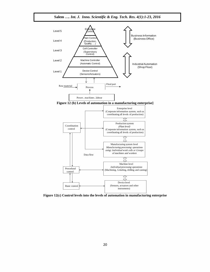
Levels of automation in a manufacturing enterprise
The levels of automation in a manufacturing enterprise, are: a) Device level: control system components
as sensors, actuators and other hardware components that comprise the machine level, b) Machine level:
Hardware at the device level is assembled into individual machines; examples include industrial robots,
powered conveyers, Control function at this level include performing the sequence of steps in the program
of instructions in the correct order and making sure that each step is properly executed, c) Cell or system
level: A manufacturing cell or system is group of machines or workstations connected and supported by a
material handling system, computer and other equipment appropriate to the manufacturing process,
Functions at this level include part dispatching and machine loading, coordination among machines and
material handling system, and collecting and evaluating inspection data, d) Plant level: This is the factory
or production system level, it receives instructions from the corporate information system and translates
them into operational plans for production, Functions at this level include: order processing, process
planning, inventory control, purchasing, material requirements, shop floor control, and quality control, f)
Enterprise level .This is the highest level, consisting of the corporate information system, it is concerned
with all of the function necessary to manage the company: marketing and sales, accounting, design,
research, aggregate planning, and master production scheduling. these levels are shown in Figure 12(b)
Levels of industrial process control
The levels of industrial process control in manufacturing enterprise are:a) Basic control ; the lowest level
of control, and corresponding to the device level- e.g. controlling servomotors and other actuators of the
production machines, b) Procedural control ; intermediate level of control -data collected, changing
setpoints , parameters in basic control, and changing controller's gain constants , error detecting, c)
Coordination control; the highest level in control. It is corresponds to the supervisory control level, these
levels are shown in Figure 12(b,c).
Forms of computer control of manufacturing systems
as noted, PC can be made suitable for industrial environment. There are several ways in which digital
computer can be used to control a process, the most commonly used: a) Computer process monitoring;
the computer is not used to directly control the process, but used to observe of the process and associated
equipment, collecting and recording data from the process, b) Direct digital control-DDC; applied when
many processes are occurring simultaneously and must be coordinated, because the output of one process
is the input of another. Using single large computer, all local processes can be implemented, monitored,
and adjusted from the same place, enhance total system performance, the drawback is that the whole plant
is dependent on that one computer, d) Distributed control systems –DCS; The advent of small
microprocessor-based controllers has led to a new approach called distributed computer control, each
process has its own separate controller located at the site. These local controllers are interconnected via a
Salem …. Int. J. Inno. Scientific & Eng. Tech. Res. 4(1):1-23, 2016
Ok

19
LAN, so that all controllers on the network can be monitored or reprogrammed from a single supervisory
computer, Once programmed, each process is essentially operating independently. This makes for a more
robust and safe system, because all the local processes will continue to function even if the supervisory
computer or network goes down), c) Supervisory control.
Figure 12(a) Production, Manufacturing, control and automation in production system
Salem …. Int. J. Inno. Scientific & Eng. Tech. Res. 4(1):1-23, 2016
Ok
20
Enterprise Control
Plant Control
(Production, Quality, …)
Cell Controller
(Supervisory Control)
Machine Controller
(Automatic Control)
Device Control
(Sensors/Actuators)Level 1
Level 2
Level 3
Level 4
Level 5
Industrial Automation
(Shop Floor)
Business Information
(Business Office)
Raw materialFinal part
Power , machines , labour
Process
Figure 12 (b) Levels of automation in a manufacturing enterprise]
Enterprise level
(Corporate information system, such as
coordinating all levels of production)
Production system
(Plant level) (Corporate information system, such as
coordinating all levels of production)
Manufacturing system level
Manufacturing processing operations using: Individual work cells or Groups
of machines and workers
Machine level
Individual processing operations(Machining, Grinding, drilling and casting)
Device level
(Sensors, actuators and other
instruments)
Coordination
control
Procedural
control
Basic control
Data flow
Figure 12(c) Control levels into the levels of automation in manufacturing enterprise
Salem …. Int. J. Inno. Scientific & Eng. Tech. Res. 4(1):1-23, 2016
Ok

21
outputInput
Process
Desired
objectives
Feedback Actuators
Direct process
control
Supervisory control Human
interface
Figure 12(d) Supervisory control
Figure 12 (e) Distributed computer control using local controllers[15][40-42]
Figure 12 (f) Direct computer control of three processes[15][40-42]
CONCLUSION
To support educators and help students in solving Mechatronics design tasks with their specific
properties, this paper focused on control systems and control algorithms subsystems selection, evaluation,
design and synergistic integration stage in Mechatronics systems design and development methodology,
main concepts, classifications, role, description of main features and selection criteria are presented and
discussed.
REFERENCES
[1] Farhan A. Salem, Ahmad A. Mahfouz Mechatronics Design And Implementation Education-Oriented
Methodology; A Proposed Approach, Journal of Multidisciplinary Engineering Science and
Technology Volume. 1 , Issue. 03 , October – 2014.
Salem …. Int. J. Inno. Scientific & Eng. Tech. Res. 4(1):1-23, 2016
Ok

22
[2] Farhan A. Salem, Ahmad A. Mahfouz’’ A Proposed Approach to Mechatronics Design and
Implementation Education-Oriented Methodology 'Innovative Systems Design and Engineering,
Vol.4, No.10, pp 12-29, 2013.
[3] K. Craig, F. Stolfi “Teaching control system design through Mechatronics: academic and industrial
perspectives.” Mechatronics, Vol 12, No. 2, pp. 371-381,2002.
[4] Vasilije S. Vasić ,Mihailo P. Lazarević, Standard Industrial Guideline for Mechatronic Product
Design , FME Transactions, 104 , vol. 36, No 3, 2008 .
[5] Radu-Emil Precup , Stefan Preitl, Control Solutions in Mechatronics Systems, FACTA
UNIVERSITATIS (NI_S), SER.: ELEC. ENERG. vol. 18, no. 3, December 2005, 379-394.
[6] L Al-Sharif (2010), A Saleem, and TA Tutunji, Mechatronic system design: The ideal capstone
course? 7th International Symposium on Mechatronics and its Applications (ISMA), , also L Al-
Sharif "Mechatronics System Design 0908531: Course Notes", Mechatronics Engineering
Department, University of Jordan.
[7] Mihai Avram, The Control Subsystem of a Mechatronic System, Proceedings of International
Conference On Innovations, Recent Trends And Challenges In Mechatronics, Mechanical
Engineering And New High-Tech Products Development – MECAHITECH’11, vol. 3, year: 2011.
[8] Farhan A. Salem, Ahmad A. Mahfouz, Modeling and controller design for electric motor, using
different control strategies and verification using MATLAB/Simulink , Submitted and accepted , to
I.J. Intelligent Systems and Applications, Submission ID 124 , 2012.
[9] Hedaya Alasooly, Control of DC motor using different control strategies, global journal of technology
and optimization 2011.
[10] Farid Golnaraghi , Benjamin C. Kuo, Automatic control systems, John wiley &sons, 2000.
[11] D'AzzoJohn Joachim, Houpis, Constantine H, “Linear control system analysis and design:
conventional and modern“, 1988) .
[12] Hedaya Alasooly, ''Control of DC motor using different control strategies'' global journal of
technology and optimization, 2011.
[13] Farhan A. Salem, PID Controllers and Algorithms: Selection and Design Techniques Applied in
Mechatronics Systems Design - Part II, International Journal of Engineering Sciences, 2(5) May
2013, Pages: 191-203
[14] Farhan A. Salem, Controllers and Control Algorithms: Selection and Time Domain Design
Techniques Applied in Mechatronics Systems Design (Review and Research) Part I, International
Journal of Engineering Sciences, 2(5) May 2013, Pages: 160-190.
[15] Ayman A. Ali, Farhan A Salem, Fundamentals of Automation and Industrial Control Systems Using
PLC: automation and control technologies, LAP Lambert Academic Publishing (May 11 2012).
[16] Robert H, Bishop, Mechatronics systems sensors, and actuators, fundamentals and modeling, CRC
Press, 2008.
[17] Mihai Avram, Constantin Bucşan, Despina Duminică, The Control Subsystem of a Mechatronic
System, Proceedings of International Conference On Innovations, Recent Trends And Challenges In
Mechatronics, Mechanical Engineering And New High-Tech Products Development –
MECAHITECH’11, vol. 3, year: 2011
[18] Godefry Onwubolu, Mechatronics Principles and Applications
[19] Andrei DRUMEA, Paul SVASTA, MICROCONTROLLER-BASED ELECTRONIC MODULE
FOR CONTROLLING MECHATRONIC SYSTEMS , U.P.B. Sci. Bull., Series C, Vol. 71, Iss. 2,
2009
[20] Mrinmoy Sengupta ,Microcontroller Based Infrared Tracking Device In 2D Motion, International
Journal of Scientific & Engineering Research Volume 3, Issue 9, September-2012
[21] Edward A. Lee, Programmable DSP archetucture, Part I, IEEE magazine , October, 1988
[22] Robert H. Bishop, the Mechatronics Handbook, CRC, Press, 2002.
[23] D. A. Bradly, D. Dawson, N. C. Burd, A. J. Loader, Mechatronics: Electronics in Products and
Processes, chapman and hall, 1993.
Salem …. Int. J. Inno. Scientific & Eng. Tech. Res. 4(1):1-23, 2016
Ok

23
[24] K. Craig, “The role of computers in Mechatronics”, Computing in Science & Engineering, Vol. 5,
No. 2, pp. 80-85, 2003
[25] Katuhiko Ogata, Modern control engineering, third edition, Prentice Hall,1990
[26] Huong Nguyen, Introduction to Computer Science, 2009, http://cnx.org/content/col10776/1.1.
[27] Douglas J. Cooper , '' practical process control' http://www. controlguru. com/wp/ p69.html
[28] Carl A. Smith, Armando B. Corripio, Principles and practice of automatic process control, second
edition, Wiley, 2013.
[29] Astrom , Wittenmark , "Adaptive control" Addison-Wesley, 1995
[30] Report of the Task Force on Intelligent Control IEEE Control Systems Society Panos Antsaklis,
Chair, 1993.
[31] Saridis, G. N., Self Organizing Control of Stochastic Systems. Marcel Dekker, New York, 1977.
[32] Saridis, G. N. and Valavanis, K. P., Analytical design of intelligent machines. Automatica, 24:123–
133, 1988.
[33] Åström, K. J., Intelligent control. In Proc. European Control Conf., Grenoble, 1991.
[34] Robert H. Bishop , Mechatronics: an introduction. CRC, Taylor & Francis, 2006
[35] Kevin M. Passino, Fuzzy Control, Addison-Wesley , 1998.
[36] Spyros G. Tzafestas , Control systems, Robotics and automation , Expert Control Systems Vol. XVII
–
[37] F.L. Lewis, Shuzhi Sam Ge, Neural Networks in Feedback Control Systems, John Wiley, New York,
2005.
[38] By Steven W. Smith, The Scientist and Engineer's Guide to Digital Signal Processing ,
http://www.dspguide.com/ch26/2.htm
[39] http://paraschopra.com/tutorials/nn/
[40] Ayman A. Ali, Farhan A. Salem, Fundamentals of computer numerical control: Automation and
mechanization, automation and control technologies, LAP Lambert Academic Publishing, 2012.
[41] Mikell P. Groove,r Automation, Production Systems, and Computer-Integrated Manufacturing,3rd
Edition, Prentice Hall , 2007
[42] Frank D. Petruzella, 2011 by McGraw-Hill Companies in New York, NY , Frank D. Petruzella
works (PLC 7th edition 1989 , control system).
Salem …. Int. J. Inno. Scientific & Eng. Tech. Res. 4(1):1-23, 2016
Ok