Embed Size (px)
Citation preview
The RISC-V Instruction Set ManualVolume II: Privileged Architecture
Privileged Architecture Version 1.10Document Version 1.10
Warning! This draft specification may change before being accepted asstandard by the RISC-V Foundation. While the editors intend future changes
to this specification to be forward compatible, it remains possible thatimplementations made to this draft specification will not conform to the future
standard.
Editors: Andrew Waterman1, Krste Asanovic1,21SiFive Inc.,
2CS Division, EECS Department, University of California, [email protected], [email protected]
May 7, 2017
Contributors to all versions of the spec in alphabetical order (please contact editors to suggestcorrections): Krste Asanovic, Rimas Avizienis, Jacob Bachmeyer, Allen J. Baum, Paolo Bonzini,Ruslan Bukin, Christopher Celio, David Chisnall, Anthony Coulter, Palmer Dabbelt, Monte Dal-rymple, Dennis Ferguson, Mike Frysinger, John Hauser, David Horner, Olof Johansson, YunsupLee, Andrew Lutomirski, Jonathan Neuschafer, Rishiyur Nikhil, Stefan O’Rear, Albert Ou, JohnOusterhout, David Patterson, Colin Schmidt, Wesley Terpstra, Matt Thomas, Tommy Thorn, RayVanDeWalker, Megan Wachs, Andrew Waterman, and Reinoud Zandijk.
This document is released under a Creative Commons Attribution 4.0 International License.
This document is a derivative of the RISC-V privileged specification version 1.9.1 released underfollowing license: c© 2010–2017 Andrew Waterman, Yunsup Lee, Rimas Avizienis, David Patterson,Krste Asanovic. Creative Commons Attribution 4.0 International License.
Please cite as: “The RISC-V Instruction Set Manual, Volume II: Privileged Architecture, Version1.10”, Editors Andrew Waterman and Krste Asanovic, RISC-V Foundation, May 2017.
Preface
This is version 1.10 of the RISC-V privileged architecture proposal. Changes from version 1.9.1include:
• The previous version of this document was released under a Creative Commons Attribution4.0 International Licence by the original authors, and this and future versions of this documentwill be released under the same licence.
• The explicit convention on shadow CSR addresses has been removed to reclaim CSR space.Shadow CSRs can still be added as needed.
• The mvendorid register now contains the JEDEC code of the core provider as opposed toa code supplied by the Foundation. This avoids redundancy and offloads work from theFoundation.
• The interrupt-enable stack discipline has been simplified.
• An optional mechanism to change the base ISA used by supervisor and user modes has beenadded to the mstatus CSR, and the field previously called Base in misa has been renamedto MXL for consistency.
• Clarified expected use of XS to summarize additional extension state status fields in mstatus.
• Optional vectored interrupt support has been added to the mtvec and stvec CSRs.
• The SEIP and UEIP bits in the mip CSR have been redefined to support software injectionof external interrupts.
• The mbadaddr register has been subsumed by a more general mtval register that can nowcapture bad instruction bits on an illegal instruction fault to speed instruction emulation.
• The machine-mode base-and-bounds translation and protection schemes have been removedfrom the specification as part of moving the virtual memory configuration to sptbr (nowsatp). Some of the motivation for the base and bound schemes are now covered by the PMPregisters, but space remains available in mstatus to add these back at a later date if deemeduseful.
• In systems with only M-mode, or with both M-mode and U-mode but without U-modetrap support, the medeleg and mideleg registers now do not exist, whereas previously theyreturned zero.
• Virtual-memory page faults now have mcause values distinct from physical-memory accessexceptions. Page-fault exceptions can now be delegated to S-mode without delegating excep-tions generated by PMA and PMP checks.
• An optional physical-memory protection (PMP) scheme has been proposed.
• The supervisor virtual memory configuration has been moved from the mstatus register tothe sptbr register. Accordingly, the sptbr register has been renamed to satp (Supervisor
i
ii Volume II: RISC-V Privileged Architectures V1.10
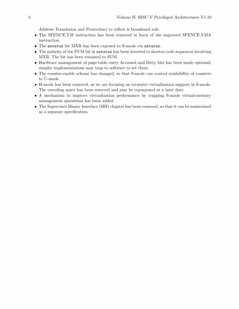
Address Translation and Protection) to reflect is broadened role.
• The SFENCE.VM instruction has been removed in favor of the improved SFENCE.VMAinstruction.
• The mstatus bit MXR has been exposed to S-mode via sstatus.
• The polarity of the PUM bit in sstatus has been inverted to shorten code sequences involvingMXR. The bit has been renamed to SUM.
• Hardware management of page-table entry Accessed and Dirty bits has been made optional;simpler implementations may trap to software to set them.
• The counter-enable scheme has changed, so that S-mode can control availability of countersto U-mode.
• H-mode has been removed, as we are focusing on recursive virtualization support in S-mode.The encoding space has been reserved and may be repurposed at a later date.
• A mechanism to improve virtualization performance by trapping S-mode virtual-memorymanagement operations has been added.
• The Supervisor Binary Interface (SBI) chapter has been removed, so that it can be maintainedas a separate specification.
Volume II: RISC-V Privileged Architectures V1.10 iii
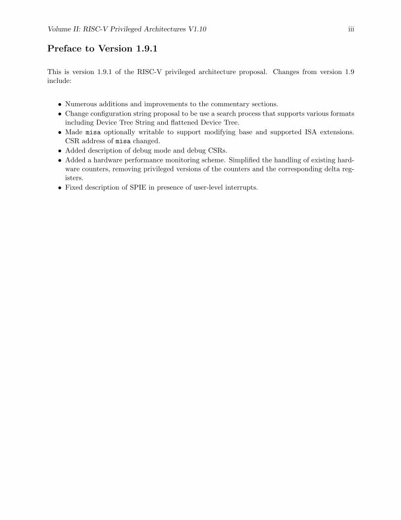
Preface to Version 1.9.1
This is version 1.9.1 of the RISC-V privileged architecture proposal. Changes from version 1.9include:
• Numerous additions and improvements to the commentary sections.
• Change configuration string proposal to be use a search process that supports various formatsincluding Device Tree String and flattened Device Tree.
• Made misa optionally writable to support modifying base and supported ISA extensions.CSR address of misa changed.
• Added description of debug mode and debug CSRs.
• Added a hardware performance monitoring scheme. Simplified the handling of existing hard-ware counters, removing privileged versions of the counters and the corresponding delta reg-isters.
• Fixed description of SPIE in presence of user-level interrupts.

iv Volume II: RISC-V Privileged Architectures V1.10
Contents
Preface i
1 Introduction 1
1.1 RISC-V Hardware Platform Terminology . . . . . . . . . . . . . . . . . . . . . . . . 1
1.2 RISC-V Privileged Software Stack Terminology . . . . . . . . . . . . . . . . . . . . . 2
1.3 Privilege Levels . . . . . . . . . . . . . . . . . . . . . . . . . . . . . . . . . . . . . . . 3
1.4 Debug Mode . . . . . . . . . . . . . . . . . . . . . . . . . . . . . . . . . . . . . . . . 5
2 Control and Status Registers (CSRs) 7
2.1 CSR Address Mapping Conventions . . . . . . . . . . . . . . . . . . . . . . . . . . . 7
2.2 CSR Listing . . . . . . . . . . . . . . . . . . . . . . . . . . . . . . . . . . . . . . . . . 9
2.3 CSR Field Specifications . . . . . . . . . . . . . . . . . . . . . . . . . . . . . . . . . . 13
3 Machine-Level ISA, version 1.10 15
3.1 Machine-Level CSRs . . . . . . . . . . . . . . . . . . . . . . . . . . . . . . . . . . . . 15
3.1.1 Machine ISA Register misa . . . . . . . . . . . . . . . . . . . . . . . . . . . . 15
3.1.2 Machine Vendor ID Register mvendorid . . . . . . . . . . . . . . . . . . . . . 18
3.1.3 Machine Architecture ID Register marchid . . . . . . . . . . . . . . . . . . . 18
3.1.4 Machine Implementation ID Register mimpid . . . . . . . . . . . . . . . . . . 19
3.1.5 Hart ID Register mhartid . . . . . . . . . . . . . . . . . . . . . . . . . . . . . 19
3.1.6 Machine Status Register (mstatus) . . . . . . . . . . . . . . . . . . . . . . . . 19
3.1.7 Privilege and Global Interrupt-Enable Stack in mstatus register . . . . . . . 20
v
vi Volume II: RISC-V Privileged Architectures V1.10
3.1.8 Base ISA Control in mstatus Register . . . . . . . . . . . . . . . . . . . . . . 21
3.1.9 Memory Privilege in mstatus Register . . . . . . . . . . . . . . . . . . . . . . 22
3.1.10 Virtualization Support in mstatus Register . . . . . . . . . . . . . . . . . . . 22
3.1.11 Extension Context Status in mstatus Register . . . . . . . . . . . . . . . . . 23
3.1.12 Machine Trap-Vector Base-Address Register (mtvec) . . . . . . . . . . . . . . 26
3.1.13 Machine Trap Delegation Registers (medeleg and mideleg) . . . . . . . . . . 27
3.1.14 Machine Interrupt Registers (mip and mie) . . . . . . . . . . . . . . . . . . . 28
3.1.15 Machine Timer Registers (mtime and mtimecmp) . . . . . . . . . . . . . . . . 30
3.1.16 Hardware Performance Monitor . . . . . . . . . . . . . . . . . . . . . . . . . . 31
3.1.17 Counter-Enable Registers ([m|h|s]counteren) . . . . . . . . . . . . . . . . . 32
3.1.18 Machine Scratch Register (mscratch) . . . . . . . . . . . . . . . . . . . . . . 33
3.1.19 Machine Exception Program Counter (mepc) . . . . . . . . . . . . . . . . . . 34
3.1.20 Machine Cause Register (mcause) . . . . . . . . . . . . . . . . . . . . . . . . 34
3.1.21 Machine Trap Value (mtval) Register . . . . . . . . . . . . . . . . . . . . . . 35
3.2 Machine-Mode Privileged Instructions . . . . . . . . . . . . . . . . . . . . . . . . . . 37
3.2.1 Environment Call and Breakpoint . . . . . . . . . . . . . . . . . . . . . . . . 37
3.2.2 Trap-Return Instructions . . . . . . . . . . . . . . . . . . . . . . . . . . . . . 37
3.2.3 Wait for Interrupt . . . . . . . . . . . . . . . . . . . . . . . . . . . . . . . . . 38
3.3 Reset . . . . . . . . . . . . . . . . . . . . . . . . . . . . . . . . . . . . . . . . . . . . . 39
3.4 Non-Maskable Interrupts . . . . . . . . . . . . . . . . . . . . . . . . . . . . . . . . . . 39
3.5 Physical Memory Attributes . . . . . . . . . . . . . . . . . . . . . . . . . . . . . . . . 39
3.5.1 Main Memory versus I/O versus Empty Regions . . . . . . . . . . . . . . . . 41
3.5.2 Supported Access Type PMAs . . . . . . . . . . . . . . . . . . . . . . . . . . 41
3.5.3 Atomicity PMAs . . . . . . . . . . . . . . . . . . . . . . . . . . . . . . . . . . 41
3.5.4 Memory-Ordering PMAs . . . . . . . . . . . . . . . . . . . . . . . . . . . . . 42
3.5.5 Coherence and Cacheability PMAs . . . . . . . . . . . . . . . . . . . . . . . . 43
3.5.6 Idempotency PMAs . . . . . . . . . . . . . . . . . . . . . . . . . . . . . . . . 44
3.6 Physical Memory Protection . . . . . . . . . . . . . . . . . . . . . . . . . . . . . . . . 44
Volume II: RISC-V Privileged Architectures V1.10 vii
3.6.1 Physical Memory Protection CSRs . . . . . . . . . . . . . . . . . . . . . . . . 45
4 Supervisor-Level ISA, Version 1.10 49
4.1 Supervisor CSRs . . . . . . . . . . . . . . . . . . . . . . . . . . . . . . . . . . . . . . 49
4.1.1 Supervisor Status Register (sstatus) . . . . . . . . . . . . . . . . . . . . . . 49
4.1.2 Base ISA Control in sstatus Register . . . . . . . . . . . . . . . . . . . . . . 50
4.1.3 Memory Privilege in sstatus Register . . . . . . . . . . . . . . . . . . . . . . 51
4.1.4 Supervisor Trap Vector Base Address Register (stvec) . . . . . . . . . . . . . 51
4.1.5 Supervisor Interrupt Registers (sip and sie) . . . . . . . . . . . . . . . . . . 52
4.1.6 Supervisor Timers and Performance Counters . . . . . . . . . . . . . . . . . . 53
4.1.7 Counter-Enable Register (scounteren) . . . . . . . . . . . . . . . . . . . . . 53
4.1.8 Supervisor Scratch Register (sscratch) . . . . . . . . . . . . . . . . . . . . . 54
4.1.9 Supervisor Exception Program Counter (sepc) . . . . . . . . . . . . . . . . . 54
4.1.10 Supervisor Cause Register (scause) . . . . . . . . . . . . . . . . . . . . . . . 54
4.1.11 Supervisor Trap Value (stval) Register . . . . . . . . . . . . . . . . . . . . . 55
4.1.12 Supervisor Address Translation and Protection (satp) Register . . . . . . . . 56
4.2 Supervisor Instructions . . . . . . . . . . . . . . . . . . . . . . . . . . . . . . . . . . . 58
4.2.1 Supervisor Memory-Management Fence Instruction . . . . . . . . . . . . . . . 58
4.3 Sv32: Page-Based 32-bit Virtual-Memory Systems . . . . . . . . . . . . . . . . . . . 59
4.3.1 Addressing and Memory Protection . . . . . . . . . . . . . . . . . . . . . . . 59
4.3.2 Virtual Address Translation Process . . . . . . . . . . . . . . . . . . . . . . . 62
4.4 Sv39: Page-Based 39-bit Virtual-Memory System . . . . . . . . . . . . . . . . . . . . 62
4.4.1 Addressing and Memory Protection . . . . . . . . . . . . . . . . . . . . . . . 63
4.5 Sv48: Page-Based 48-bit Virtual-Memory System . . . . . . . . . . . . . . . . . . . . 63
4.5.1 Addressing and Memory Protection . . . . . . . . . . . . . . . . . . . . . . . 64
5 Hypervisor Extensions, Version 0.0 65
6 RISC-V Privileged Instruction Set Listings 67
viii Volume II: RISC-V Privileged Architectures V1.10
7 Platform-Level Interrupt Controller (PLIC) 69
7.1 PLIC Overview . . . . . . . . . . . . . . . . . . . . . . . . . . . . . . . . . . . . . . . 69
7.2 Interrupt Sources . . . . . . . . . . . . . . . . . . . . . . . . . . . . . . . . . . . . . . 69
7.2.1 Local Interrupt Sources . . . . . . . . . . . . . . . . . . . . . . . . . . . . . . 70
7.2.2 Global Interrupt Sources . . . . . . . . . . . . . . . . . . . . . . . . . . . . . . 71
7.3 Interrupt Targets and Hart Contexts . . . . . . . . . . . . . . . . . . . . . . . . . . . 71
7.4 Interrupt Gateways . . . . . . . . . . . . . . . . . . . . . . . . . . . . . . . . . . . . . 71
7.5 Interrupt Identifiers (IDs) . . . . . . . . . . . . . . . . . . . . . . . . . . . . . . . . . 72
7.6 Interrupt Priorities . . . . . . . . . . . . . . . . . . . . . . . . . . . . . . . . . . . . . 72
7.7 Interrupt Enables . . . . . . . . . . . . . . . . . . . . . . . . . . . . . . . . . . . . . . 73
7.8 Interrupt Priority Thresholds . . . . . . . . . . . . . . . . . . . . . . . . . . . . . . . 73
7.9 Interrupt Notifications . . . . . . . . . . . . . . . . . . . . . . . . . . . . . . . . . . . 74
7.10 Interrupt Claims . . . . . . . . . . . . . . . . . . . . . . . . . . . . . . . . . . . . . . 74
7.11 Interrupt Completion . . . . . . . . . . . . . . . . . . . . . . . . . . . . . . . . . . . . 75
7.12 Interrupt Flow . . . . . . . . . . . . . . . . . . . . . . . . . . . . . . . . . . . . . . . 75
7.13 PLIC Core Specification . . . . . . . . . . . . . . . . . . . . . . . . . . . . . . . . . . 76
7.14 Controlling Access to the PLIC . . . . . . . . . . . . . . . . . . . . . . . . . . . . . . 76
8 Machine Configuration Description 77
8.1 Configuration String Search Procedure . . . . . . . . . . . . . . . . . . . . . . . . . . 77
9 History 79
9.1 Research Funding at UC Berkeley . . . . . . . . . . . . . . . . . . . . . . . . . . . . 79
Chapter 1
Introduction
This is a draft of the privileged architecture description document for RISC-V. Feedback welcome.Changes will occur before the final release.
This document describes the RISC-V privileged architecture, which covers all aspects of RISC-Vsystems beyond the user-level ISA, including privileged instructions as well as additional function-ality required for running operating systems and attaching external devices.
Commentary on our design decisions is formatted as in this paragraph, and can be skipped if thereader is only interested in the specification itself.
We briefly note that the entire privileged-level design described in this document could be replacedwith an entirely different privileged-level design without changing the user-level ISA, and pos-sibly without even changing the ABI. In particular, this privileged specification was designed torun existing popular operating systems, and so embodies the conventional level-based protectionmodel. Alternate privileged specifications could embody other more flexible protection-domainmodels.
1.1 RISC-V Hardware Platform Terminology
A RISC-V hardware platform can contain one or more RISC-V-compatible processing cores to-gether with other non-RISC-V-compatible cores, fixed-function accelerators, various physical mem-ory structures, I/O devices, and an interconnect structure to allow the components to communicate.
A component is termed a core if it contains an independent instruction fetch unit. A RISC-V-compatible core might support multiple RISC-V-compatible hardware threads, or harts, throughmultithreading.
A RISC-V core might have additional specialized instruction set extensions or an added coprocessor.We use the term coprocessor to refer to a unit that is attached to a RISC-V core and is mostlysequenced by a RISC-V instruction stream, but which contains additional architectural state andinstruction set extensions, and possibly some limited autonomy relative to the primary RISC-Vinstruction stream.
1
2 Volume II: RISC-V Privileged Architectures V1.10
We use the term accelerator to refer to either a non-programmable fixed-function unit or a core thatcan operate autonomously but is specialized for certain tasks. In RISC-V systems, we expect manyprogrammable accelerators will be RISC-V-based cores with specialized instruction set extensionsand/or customized coprocessors. An important class of RISC-V accelerators are I/O accelerators,which offload I/O processing tasks from the main application cores.
The system-level organization of a RISC-V hardware platform can range from a single-core micro-controller to a many-thousand-node cluster of shared-memory manycore server nodes. Even smallsystems-on-a-chip might be structured as a hierarchy of multicomputers and/or multiprocessors tomodularize development effort or to provide secure isolation between subsystems.
This document focuses on the privileged architecture visible to each hart (hardware thread) runningwithin a uniprocessor or a shared-memory multiprocessor.
1.2 RISC-V Privileged Software Stack Terminology
This section describes the terminology we use to describe components of the wide range of possibleprivileged software stacks for RISC-V.
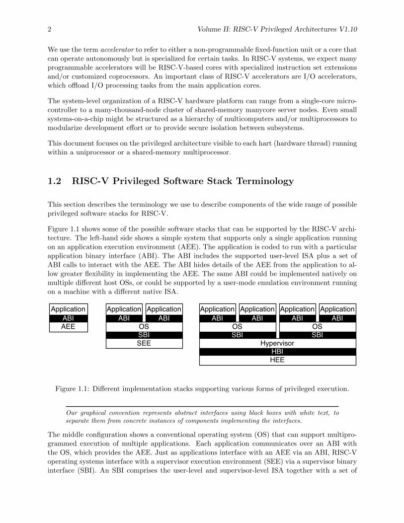
Figure 1.1 shows some of the possible software stacks that can be supported by the RISC-V archi-tecture. The left-hand side shows a simple system that supports only a single application runningon an application execution environment (AEE). The application is coded to run with a particularapplication binary interface (ABI). The ABI includes the supported user-level ISA plus a set ofABI calls to interact with the AEE. The ABI hides details of the AEE from the application to al-low greater flexibility in implementing the AEE. The same ABI could be implemented natively onmultiple different host OSs, or could be supported by a user-mode emulation environment runningon a machine with a different native ISA.
ApplicationABIAEE
ApplicationABI
OSSBISEE
ApplicationABI
SBIHypervisor
ApplicationABI
OS
ApplicationABI
ApplicationABI
OS
ApplicationABI
SBI
HBIHEE
Figure 1.1: Different implementation stacks supporting various forms of privileged execution.
Our graphical convention represents abstract interfaces using black boxes with white text, toseparate them from concrete instances of components implementing the interfaces.
The middle configuration shows a conventional operating system (OS) that can support multipro-grammed execution of multiple applications. Each application communicates over an ABI withthe OS, which provides the AEE. Just as applications interface with an AEE via an ABI, RISC-Voperating systems interface with a supervisor execution environment (SEE) via a supervisor binaryinterface (SBI). An SBI comprises the user-level and supervisor-level ISA together with a set of
Volume II: RISC-V Privileged Architectures V1.10 3
SBI function calls. Using a single SBI across all SEE implementations allows a single OS binaryimage to run on any SEE. The SEE can be a simple boot loader and BIOS-style IO system in alow-end hardware platform, or a hypervisor-provided virtual machine in a high-end server, or athin translation layer over a host operating system in an architecture simulation environment.
Most supervisor-level ISA definitions do not separate the SBI from the execution environmentand/or the hardware platform, complicating virtualization and bring-up of new hardware plat-forms.
The rightmost configuration shows a virtual machine monitor configuration where multiple multi-programmed OSs are supported by a single hypervisor. Each OS communicates via an SBI withthe hypervisor, which provides the SEE. The hypervisor communicates with the hypervisor execu-tion environment (HEE) using a hypervisor binary interface (HBI), to isolate the hypervisor fromdetails of the hardware platform.
The ABI, SBI, and HBI are still a work-in-progress, but we are now prioritizing support forType-2 hypervisors where the SBI is provided recursively by an S-mode OS.
Hardware implementations of the RISC-V ISA will generally require additional features beyond theprivileged ISA to support the various execution environments (AEE, SEE, or HEE).
1.3 Privilege Levels
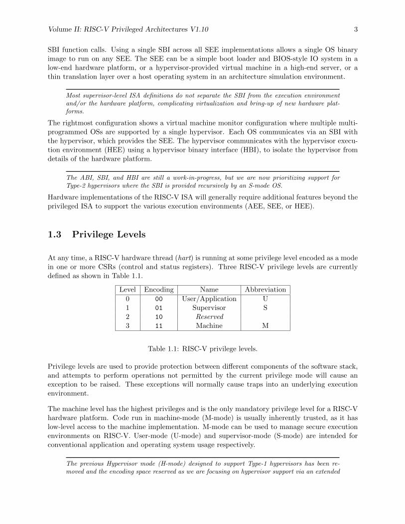
At any time, a RISC-V hardware thread (hart) is running at some privilege level encoded as a modein one or more CSRs (control and status registers). Three RISC-V privilege levels are currentlydefined as shown in Table 1.1.
Level Encoding Name Abbreviation
0 00 User/Application U1 01 Supervisor S2 10 Reserved3 11 Machine M
Table 1.1: RISC-V privilege levels.
Privilege levels are used to provide protection between different components of the software stack,and attempts to perform operations not permitted by the current privilege mode will cause anexception to be raised. These exceptions will normally cause traps into an underlying executionenvironment.
The machine level has the highest privileges and is the only mandatory privilege level for a RISC-Vhardware platform. Code run in machine-mode (M-mode) is usually inherently trusted, as it haslow-level access to the machine implementation. M-mode can be used to manage secure executionenvironments on RISC-V. User-mode (U-mode) and supervisor-mode (S-mode) are intended forconventional application and operating system usage respectively.
The previous Hypervisor mode (H-mode) designed to support Type-1 hypervisors has been re-moved and the encoding space reserved as we are focusing on hypervisor support via an extended
4 Volume II: RISC-V Privileged Architectures V1.10
S mode suitable for both Type-1 and Type-2 hypervisors as described in Chapter 5. The encod-ing space for H is reserved for future use and to avoid backwards incompatible changes in bitpositions in various status regusters. The bit positions might be reused in the future for differentType-1 hypervisor support or possibly additional secure execution modes.
Each privilege level has a core set of privileged ISA extensions with optional extensions and variants.For example, machine-mode supports several optional standard variants for address translation andmemory protection. Also, supervisor-mode can be extended to support Type-2 hypervisor executionas described in Chapter 5.
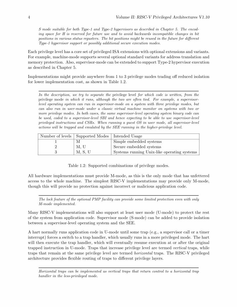
Implementations might provide anywhere from 1 to 3 privilege modes trading off reduced isolationfor lower implementation cost, as shown in Table 1.2.
In the description, we try to separate the privilege level for which code is written, from theprivilege mode in which it runs, although the two are often tied. For example, a supervisor-level operating system can run in supervisor-mode on a system with three privilege modes, butcan also run in user-mode under a classic virtual machine monitor on systems with two ormore privilege modes. In both cases, the same supervisor-level operating system binary code canbe used, coded to a supervisor-level SBI and hence expecting to be able to use supervisor-levelprivileged instructions and CSRs. When running a guest OS in user mode, all supervisor-levelactions will be trapped and emulated by the SEE running in the higher-privilege level.
Number of levels Supported Modes Intended Usage
1 M Simple embedded systems2 M, U Secure embedded systems3 M, S, U Systems running Unix-like operating systems
Table 1.2: Supported combinations of privilege modes.
All hardware implementations must provide M-mode, as this is the only mode that has unfetteredaccess to the whole machine. The simplest RISC-V implementations may provide only M-mode,though this will provide no protection against incorrect or malicious application code.
The lock feature of the optional PMP facility can provide some limited protection even with onlyM-mode implemented.
Many RISC-V implementations will also support at least user mode (U-mode) to protect the restof the system from application code. Supervisor mode (S-mode) can be added to provide isolationbetween a supervisor-level operating system and the SEE.
A hart normally runs application code in U-mode until some trap (e.g., a supervisor call or a timerinterrupt) forces a switch to a trap handler, which usually runs in a more privileged mode. The hartwill then execute the trap handler, which will eventually resume execution at or after the originaltrapped instruction in U-mode. Traps that increase privilege level are termed vertical traps, whiletraps that remain at the same privilege level are termed horizontal traps. The RISC-V privilegedarchitecture provides flexible routing of traps to different privilege layers.
Horizontal traps can be implemented as vertical traps that return control to a horizontal traphandler in the less-privileged mode.
Volume II: RISC-V Privileged Architectures V1.10 5
1.4 Debug Mode
Implementations may also include a debug mode to support off-chip debugging and/or manufac-turing test. Debug mode (D-mode) can be considered an additional privilege mode, with even moreaccess than M-mode. The separate debug specification proposal describes operation of a RISC-Vhart in debug mode. Debug mode reserves a few CSR addresses that are only accessible in D-mode,and may also reserve some portions of the physical memory space on a platform.

6 Volume II: RISC-V Privileged Architectures V1.10
Chapter 2
Control and Status Registers (CSRs)
The SYSTEM major opcode is used to encode all privileged instructions in the RISC-V ISA. Thesecan be divided into two main classes: those that atomically read-modify-write control and statusregisters (CSRs), and all other privileged instructions. In addition to the user-level state describedin Volume I of this manual, an implementation may contain additional CSRs, accessible by somesubset of the privilege levels using the CSR instructions described in the user-level manual. Inthis chapter, we map out the CSR address space. The following chapters describe the function ofeach of the CSRs according to privilege level, as well as the other privileged instructions whichare generally closely associated with a particular privilege level. Note that although CSRs andinstructions are associated with one privilege level, they are also accessible at all higher privilegelevels.
2.1 CSR Address Mapping Conventions
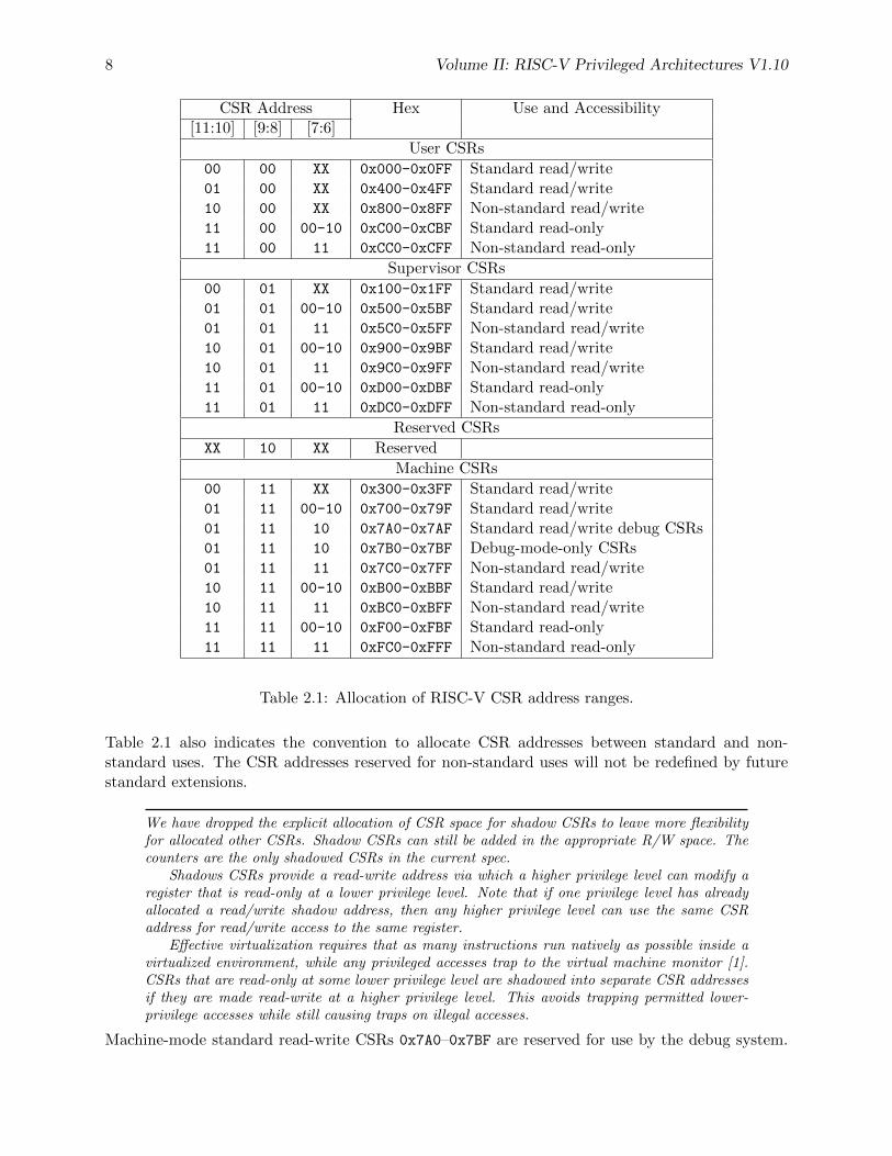
The standard RISC-V ISA sets aside a 12-bit encoding space (csr[11:0]) for up to 4,096 CSRs.By convention, the upper 4 bits of the CSR address (csr[11:8]) are used to encode the read andwrite accessibility of the CSRs according to privilege level as shown in Table 2.1. The top two bits(csr[11:10]) indicate whether the register is read/write (00, 01, or 10) or read-only (11). The nexttwo bits (csr[9:8]) encode the lowest privilege level that can access the CSR.
The CSR address convention uses the upper bits of the CSR address to encode default accessprivileges. This simplifies error checking in the hardware and provides a larger CSR space, butdoes constrain the mapping of CSRs into the address space.
Implementations might allow a more-privileged level to trap otherwise permitted CSR ac-cesses by a less-privileged level to allow these accesses to be intercepted. This change should betransparent to the less-privileged software.
Attempts to access a non-existent CSR raise an illegal instruction exception. Attempts to access aCSR without appropriate privilege level or to write a read-only register also raise illegal instructionexceptions. A read/write register might also contain some bits that are read-only, in which casewrites to the read-only bits are ignored.
7
8 Volume II: RISC-V Privileged Architectures V1.10
CSR Address Hex Use and Accessibility[11:10] [9:8] [7:6]
User CSRs
00 00 XX 0x000-0x0FF Standard read/write01 00 XX 0x400-0x4FF Standard read/write10 00 XX 0x800-0x8FF Non-standard read/write11 00 00-10 0xC00-0xCBF Standard read-only11 00 11 0xCC0-0xCFF Non-standard read-only
Supervisor CSRs
00 01 XX 0x100-0x1FF Standard read/write01 01 00-10 0x500-0x5BF Standard read/write01 01 11 0x5C0-0x5FF Non-standard read/write10 01 00-10 0x900-0x9BF Standard read/write10 01 11 0x9C0-0x9FF Non-standard read/write11 01 00-10 0xD00-0xDBF Standard read-only11 01 11 0xDC0-0xDFF Non-standard read-only
Reserved CSRs
XX 10 XX Reserved
Machine CSRs
00 11 XX 0x300-0x3FF Standard read/write01 11 00-10 0x700-0x79F Standard read/write01 11 10 0x7A0-0x7AF Standard read/write debug CSRs01 11 10 0x7B0-0x7BF Debug-mode-only CSRs01 11 11 0x7C0-0x7FF Non-standard read/write10 11 00-10 0xB00-0xBBF Standard read/write10 11 11 0xBC0-0xBFF Non-standard read/write11 11 00-10 0xF00-0xFBF Standard read-only11 11 11 0xFC0-0xFFF Non-standard read-only
Table 2.1: Allocation of RISC-V CSR address ranges.
Table 2.1 also indicates the convention to allocate CSR addresses between standard and non-standard uses. The CSR addresses reserved for non-standard uses will not be redefined by futurestandard extensions.
We have dropped the explicit allocation of CSR space for shadow CSRs to leave more flexibilityfor allocated other CSRs. Shadow CSRs can still be added in the appropriate R/W space. Thecounters are the only shadowed CSRs in the current spec.
Shadows CSRs provide a read-write address via which a higher privilege level can modify aregister that is read-only at a lower privilege level. Note that if one privilege level has alreadyallocated a read/write shadow address, then any higher privilege level can use the same CSRaddress for read/write access to the same register.
Effective virtualization requires that as many instructions run natively as possible inside avirtualized environment, while any privileged accesses trap to the virtual machine monitor [1].CSRs that are read-only at some lower privilege level are shadowed into separate CSR addressesif they are made read-write at a higher privilege level. This avoids trapping permitted lower-privilege accesses while still causing traps on illegal accesses.
Machine-mode standard read-write CSRs 0x7A0–0x7BF are reserved for use by the debug system.
Volume II: RISC-V Privileged Architectures V1.10 9
Implementations should raise illegal instruction exceptions on machine-mode access to these regis-ters.
2.2 CSR Listing
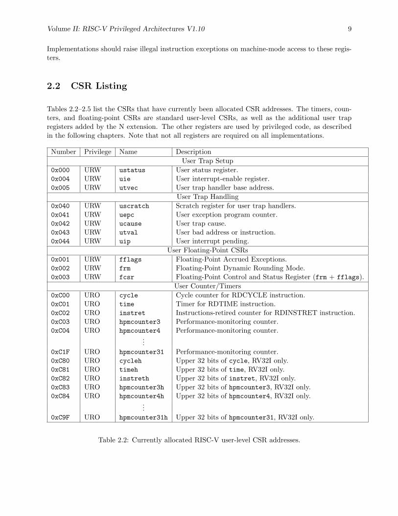
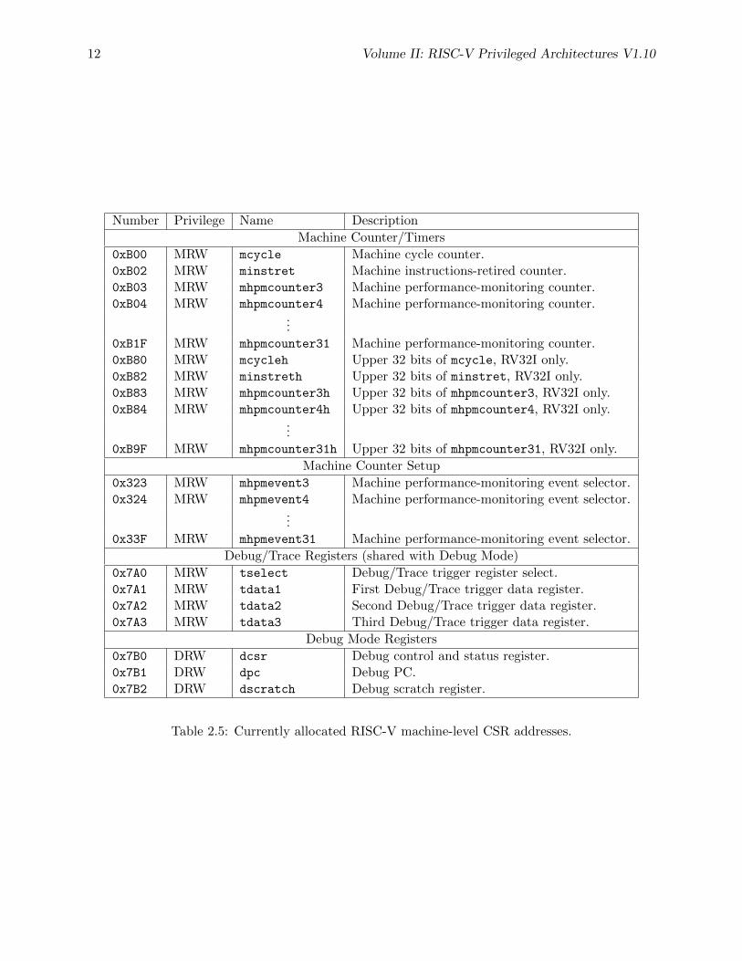
Tables 2.2–2.5 list the CSRs that have currently been allocated CSR addresses. The timers, coun-ters, and floating-point CSRs are standard user-level CSRs, as well as the additional user trapregisters added by the N extension. The other registers are used by privileged code, as describedin the following chapters. Note that not all registers are required on all implementations.
Number Privilege Name Description
User Trap Setup
0x000 URW ustatus User status register.0x004 URW uie User interrupt-enable register.0x005 URW utvec User trap handler base address.
User Trap Handling
0x040 URW uscratch Scratch register for user trap handlers.0x041 URW uepc User exception program counter.0x042 URW ucause User trap cause.0x043 URW utval User bad address or instruction.0x044 URW uip User interrupt pending.
User Floating-Point CSRs
0x001 URW fflags Floating-Point Accrued Exceptions.0x002 URW frm Floating-Point Dynamic Rounding Mode.0x003 URW fcsr Floating-Point Control and Status Register (frm + fflags).
User Counter/Timers
0xC00 URO cycle Cycle counter for RDCYCLE instruction.0xC01 URO time Timer for RDTIME instruction.0xC02 URO instret Instructions-retired counter for RDINSTRET instruction.0xC03 URO hpmcounter3 Performance-monitoring counter.0xC04 URO hpmcounter4 Performance-monitoring counter.
...0xC1F URO hpmcounter31 Performance-monitoring counter.0xC80 URO cycleh Upper 32 bits of cycle, RV32I only.0xC81 URO timeh Upper 32 bits of time, RV32I only.0xC82 URO instreth Upper 32 bits of instret, RV32I only.0xC83 URO hpmcounter3h Upper 32 bits of hpmcounter3, RV32I only.0xC84 URO hpmcounter4h Upper 32 bits of hpmcounter4, RV32I only.
...0xC9F URO hpmcounter31h Upper 32 bits of hpmcounter31, RV32I only.
Table 2.2: Currently allocated RISC-V user-level CSR addresses.
10 Volume II: RISC-V Privileged Architectures V1.10
Number Privilege Name Description
Supervisor Trap Setup
0x100 SRW sstatus Supervisor status register.0x102 SRW sedeleg Supervisor exception delegation register.0x103 SRW sideleg Supervisor interrupt delegation register.0x104 SRW sie Supervisor interrupt-enable register.0x105 SRW stvec Supervisor trap handler base address.0x106 SRW scounteren Supervisor counter enable.
Supervisor Trap Handling
0x140 SRW sscratch Scratch register for supervisor trap handlers.0x141 SRW sepc Supervisor exception program counter.0x142 SRW scause Supervisor trap cause.0x143 SRW stval Supervisor bad address or instruction.0x144 SRW sip Supervisor interrupt pending.
Supervisor Protection and Translation
0x180 SRW satp Supervisor address translation and protection.
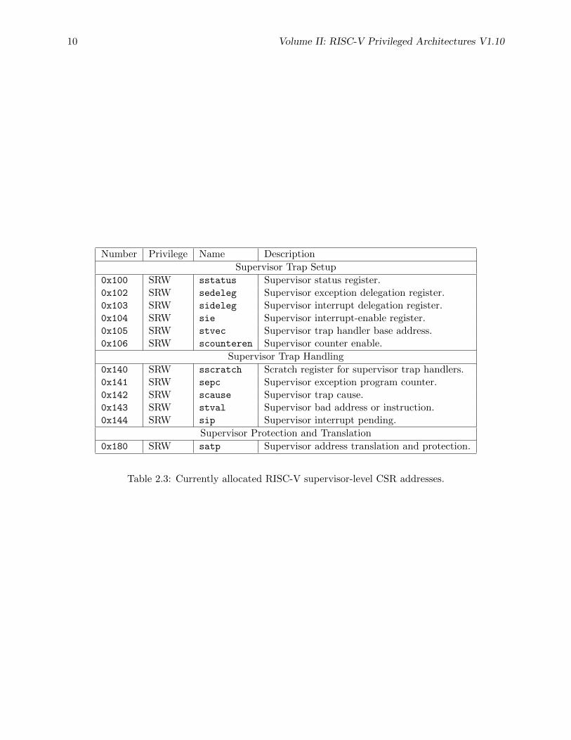
Table 2.3: Currently allocated RISC-V supervisor-level CSR addresses.
Volume II: RISC-V Privileged Architectures V1.10 11
Number Privilege Name Description
Machine Information Registers
0xF11 MRO mvendorid Vendor ID.0xF12 MRO marchid Architecture ID.0xF13 MRO mimpid Implementation ID.0xF14 MRO mhartid Hardware thread ID.
Machine Trap Setup
0x300 MRW mstatus Machine status register.0x301 MRW misa ISA and extensions0x302 MRW medeleg Machine exception delegation register.0x303 MRW mideleg Machine interrupt delegation register.0x304 MRW mie Machine interrupt-enable register.0x305 MRW mtvec Machine trap-handler base address.0x306 MRW mcounteren Machine counter enable.
Machine Trap Handling
0x340 MRW mscratch Scratch register for machine trap handlers.0x341 MRW mepc Machine exception program counter.0x342 MRW mcause Machine trap cause.0x343 MRW mtval Machine bad address or instruction.0x344 MRW mip Machine interrupt pending.
Machine Protection and Translation
0x3A0 MRW pmpcfg0 Physical memory protection configuration.0x3A1 MRW pmpcfg1 Physical memory protection configuration, RV32 only.0x3A2 MRW pmpcfg2 Physical memory protection configuration.0x3A3 MRW pmpcfg3 Physical memory protection configuration, RV32 only.0x3B0 MRW pmpaddr0 Physical memory protection address register.0x3B1 MRW pmpaddr1 Physical memory protection address register.
...0x3BF MRW pmpaddr15 Physical memory protection address register.
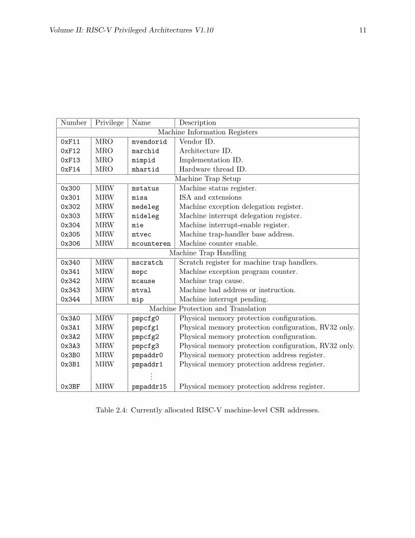
Table 2.4: Currently allocated RISC-V machine-level CSR addresses.
12 Volume II: RISC-V Privileged Architectures V1.10
Number Privilege Name Description
Machine Counter/Timers
0xB00 MRW mcycle Machine cycle counter.0xB02 MRW minstret Machine instructions-retired counter.0xB03 MRW mhpmcounter3 Machine performance-monitoring counter.0xB04 MRW mhpmcounter4 Machine performance-monitoring counter.
...0xB1F MRW mhpmcounter31 Machine performance-monitoring counter.0xB80 MRW mcycleh Upper 32 bits of mcycle, RV32I only.0xB82 MRW minstreth Upper 32 bits of minstret, RV32I only.0xB83 MRW mhpmcounter3h Upper 32 bits of mhpmcounter3, RV32I only.0xB84 MRW mhpmcounter4h Upper 32 bits of mhpmcounter4, RV32I only.
...0xB9F MRW mhpmcounter31h Upper 32 bits of mhpmcounter31, RV32I only.
Machine Counter Setup
0x323 MRW mhpmevent3 Machine performance-monitoring event selector.0x324 MRW mhpmevent4 Machine performance-monitoring event selector.
...0x33F MRW mhpmevent31 Machine performance-monitoring event selector.
Debug/Trace Registers (shared with Debug Mode)
0x7A0 MRW tselect Debug/Trace trigger register select.0x7A1 MRW tdata1 First Debug/Trace trigger data register.0x7A2 MRW tdata2 Second Debug/Trace trigger data register.0x7A3 MRW tdata3 Third Debug/Trace trigger data register.
Debug Mode Registers
0x7B0 DRW dcsr Debug control and status register.0x7B1 DRW dpc Debug PC.0x7B2 DRW dscratch Debug scratch register.
Table 2.5: Currently allocated RISC-V machine-level CSR addresses.
Volume II: RISC-V Privileged Architectures V1.10 13
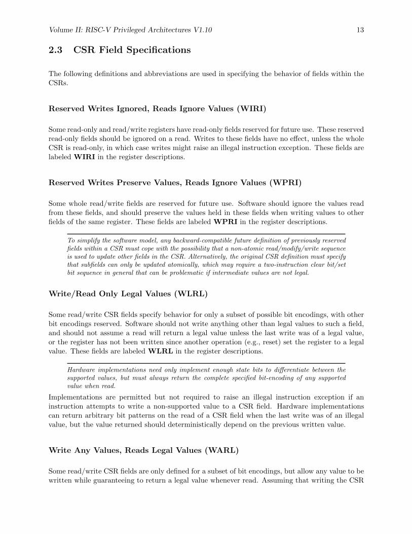
2.3 CSR Field Specifications
The following definitions and abbreviations are used in specifying the behavior of fields within theCSRs.
Reserved Writes Ignored, Reads Ignore Values (WIRI)
Some read-only and read/write registers have read-only fields reserved for future use. These reservedread-only fields should be ignored on a read. Writes to these fields have no effect, unless the wholeCSR is read-only, in which case writes might raise an illegal instruction exception. These fields arelabeled WIRI in the register descriptions.
Reserved Writes Preserve Values, Reads Ignore Values (WPRI)
Some whole read/write fields are reserved for future use. Software should ignore the values readfrom these fields, and should preserve the values held in these fields when writing values to otherfields of the same register. These fields are labeled WPRI in the register descriptions.
To simplify the software model, any backward-compatible future definition of previously reservedfields within a CSR must cope with the possibility that a non-atomic read/modify/write sequenceis used to update other fields in the CSR. Alternatively, the original CSR definition must specifythat subfields can only be updated atomically, which may require a two-instruction clear bit/setbit sequence in general that can be problematic if intermediate values are not legal.
Write/Read Only Legal Values (WLRL)
Some read/write CSR fields specify behavior for only a subset of possible bit encodings, with otherbit encodings reserved. Software should not write anything other than legal values to such a field,and should not assume a read will return a legal value unless the last write was of a legal value,or the register has not been written since another operation (e.g., reset) set the register to a legalvalue. These fields are labeled WLRL in the register descriptions.
Hardware implementations need only implement enough state bits to differentiate between thesupported values, but must always return the complete specified bit-encoding of any supportedvalue when read.
Implementations are permitted but not required to raise an illegal instruction exception if aninstruction attempts to write a non-supported value to a CSR field. Hardware implementationscan return arbitrary bit patterns on the read of a CSR field when the last write was of an illegalvalue, but the value returned should deterministically depend on the previous written value.
Write Any Values, Reads Legal Values (WARL)
Some read/write CSR fields are only defined for a subset of bit encodings, but allow any value to bewritten while guaranteeing to return a legal value whenever read. Assuming that writing the CSR

14 Volume II: RISC-V Privileged Architectures V1.10
has no other side effects, the range of supported values can be determined by attempting to writea desired setting then reading to see if the value was retained. These fields are labeled WARL inthe register descriptions.
Implementations will not raise an exception on writes of unsupported values to an WARL field.Implementations must always deterministically return the same legal value after a given illegalvalue is written.
Chapter 3
Machine-Level ISA, version 1.10
This chapter describes the machine-level operations available in machine-mode (M-mode), which isthe highest privilege mode in a RISC-V system. M-mode is the only mandatory privilege mode ina RISC-V hardware implementation. M-mode is used for low-level access to a hardware platformand is the first mode entered at reset. M-mode can also be used to implement features that are toodifficult or expensive to implement in hardware directly. The RISC-V machine-level ISA containsa common core that is extended depending on which other privilege levels are supported and otherdetails of the hardware implementation.
3.1 Machine-Level CSRs
In addition to the machine-level CSRs described in this section, M-mode code can access all CSRsat lower privilege levels.
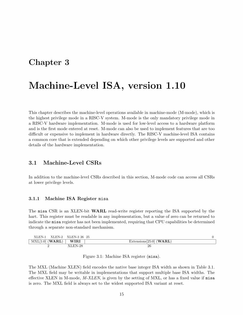
3.1.1 Machine ISA Register misa
The misa CSR is an XLEN-bit WARL read-write register reporting the ISA supported by thehart. This register must be readable in any implementation, but a value of zero can be returned toindicate the misa register has not been implemented, requiring that CPU capabilities be determinedthrough a separate non-standard mechanism.
XLEN-1 XLEN-2 XLEN-3 26 25 0
MXL[1:0] (WARL) WIRI Extensions[25:0] (WARL)
2 XLEN-28 26
Figure 3.1: Machine ISA register (misa).
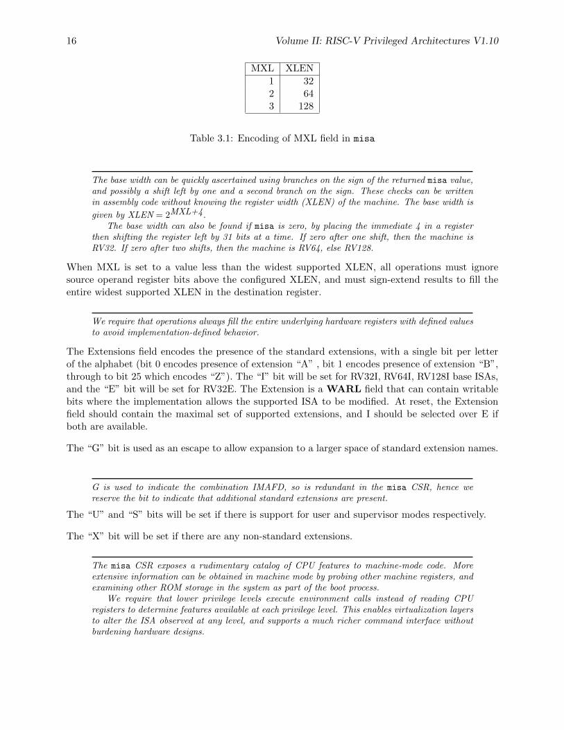
The MXL (Machine XLEN) field encodes the native base integer ISA width as shown in Table 3.1.The MXL field may be writable in implementations that support multiple base ISA widths. Theeffective XLEN in M-mode, M-XLEN, is given by the setting of MXL, or has a fixed value if misais zero. The MXL field is always set to the widest supported ISA variant at reset.
15
16 Volume II: RISC-V Privileged Architectures V1.10
MXL XLEN
1 322 643 128
Table 3.1: Encoding of MXL field in misa
The base width can be quickly ascertained using branches on the sign of the returned misa value,and possibly a shift left by one and a second branch on the sign. These checks can be writtenin assembly code without knowing the register width (XLEN) of the machine. The base width is
given by XLEN = 2MXL+4.The base width can also be found if misa is zero, by placing the immediate 4 in a register
then shifting the register left by 31 bits at a time. If zero after one shift, then the machine isRV32. If zero after two shifts, then the machine is RV64, else RV128.
When MXL is set to a value less than the widest supported XLEN, all operations must ignoresource operand register bits above the configured XLEN, and must sign-extend results to fill theentire widest supported XLEN in the destination register.
We require that operations always fill the entire underlying hardware registers with defined valuesto avoid implementation-defined behavior.
The Extensions field encodes the presence of the standard extensions, with a single bit per letterof the alphabet (bit 0 encodes presence of extension “A” , bit 1 encodes presence of extension “B”,through to bit 25 which encodes “Z”). The “I” bit will be set for RV32I, RV64I, RV128I base ISAs,and the “E” bit will be set for RV32E. The Extension is a WARL field that can contain writablebits where the implementation allows the supported ISA to be modified. At reset, the Extensionfield should contain the maximal set of supported extensions, and I should be selected over E ifboth are available.
The “G” bit is used as an escape to allow expansion to a larger space of standard extension names.
G is used to indicate the combination IMAFD, so is redundant in the misa CSR, hence wereserve the bit to indicate that additional standard extensions are present.
The “U” and “S” bits will be set if there is support for user and supervisor modes respectively.
The “X” bit will be set if there are any non-standard extensions.
The misa CSR exposes a rudimentary catalog of CPU features to machine-mode code. Moreextensive information can be obtained in machine mode by probing other machine registers, andexamining other ROM storage in the system as part of the boot process.
We require that lower privilege levels execute environment calls instead of reading CPUregisters to determine features available at each privilege level. This enables virtualization layersto alter the ISA observed at any level, and supports a much richer command interface withoutburdening hardware designs.
Volume II: RISC-V Privileged Architectures V1.10 17
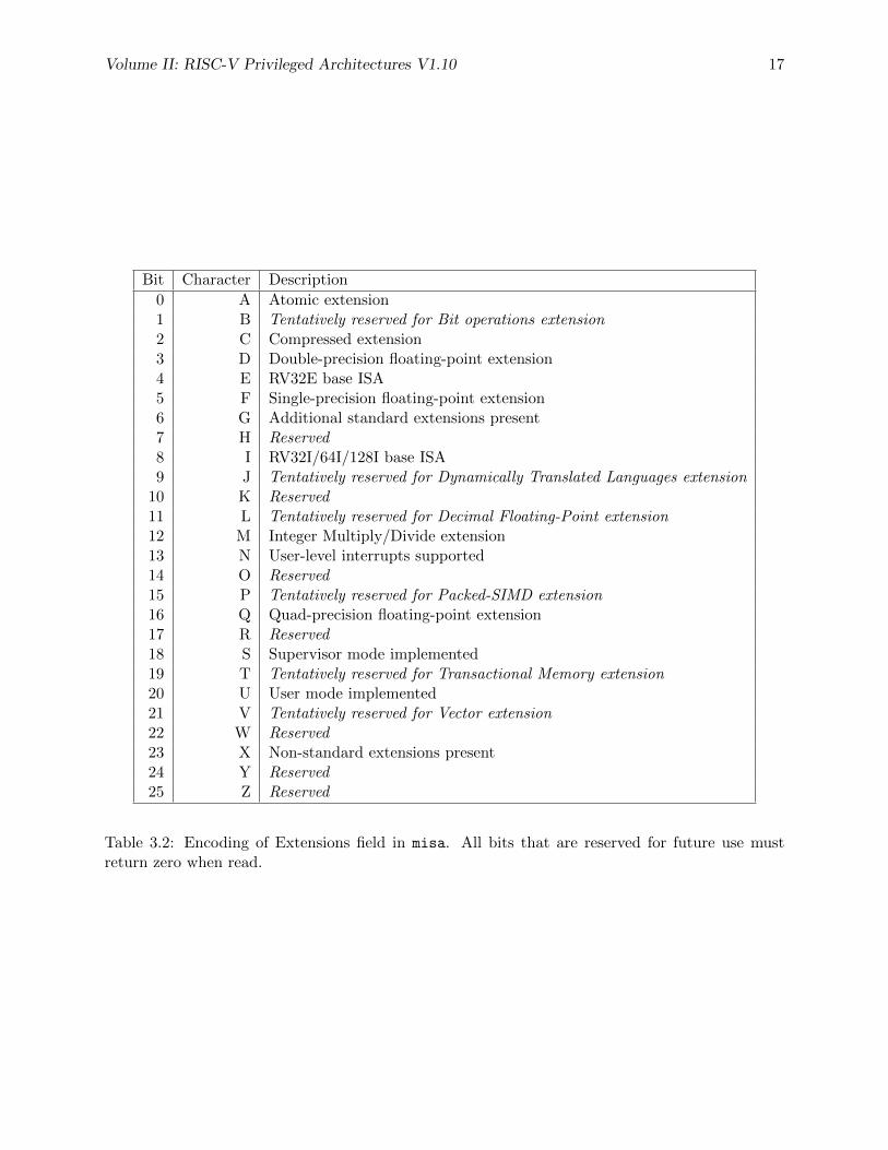
Bit Character Description
0 A Atomic extension1 B Tentatively reserved for Bit operations extension2 C Compressed extension3 D Double-precision floating-point extension4 E RV32E base ISA5 F Single-precision floating-point extension6 G Additional standard extensions present7 H Reserved8 I RV32I/64I/128I base ISA9 J Tentatively reserved for Dynamically Translated Languages extension
10 K Reserved11 L Tentatively reserved for Decimal Floating-Point extension12 M Integer Multiply/Divide extension13 N User-level interrupts supported14 O Reserved15 P Tentatively reserved for Packed-SIMD extension16 Q Quad-precision floating-point extension17 R Reserved18 S Supervisor mode implemented19 T Tentatively reserved for Transactional Memory extension20 U User mode implemented21 V Tentatively reserved for Vector extension22 W Reserved23 X Non-standard extensions present24 Y Reserved25 Z Reserved
Table 3.2: Encoding of Extensions field in misa. All bits that are reserved for future use mustreturn zero when read.
18 Volume II: RISC-V Privileged Architectures V1.10
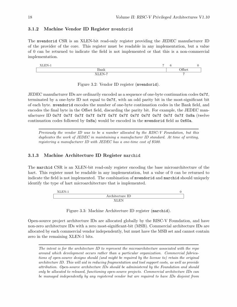
3.1.2 Machine Vendor ID Register mvendorid
The mvendorid CSR is an XLEN-bit read-only register providing the JEDEC manufacturer IDof the provider of the core. This register must be readable in any implementation, but a valueof 0 can be returned to indicate the field is not implemented or that this is a non-commercialimplementation.
XLEN-1 7 6 0
Bank Offset
XLEN-7 7
Figure 3.2: Vendor ID register (mvendorid).
JEDEC manufacturer IDs are ordinarily encoded as a sequence of one-byte continuation codes 0x7f,terminated by a one-byte ID not equal to 0x7f, with an odd parity bit in the most-significant bitof each byte. mvendorid encodes the number of one-byte continuation codes in the Bank field, andencodes the final byte in the Offset field, discarding the parity bit. For example, the JEDEC man-ufacturer ID 0x7f 0x7f 0x7f 0x7f 0x7f 0x7f 0x7f 0x7f 0x7f 0x7f 0x7f 0x7f 0x8a (twelvecontinuation codes followed by 0x8a) would be encoded in the mvendorid field as 0x60a.
Previously the vendor ID was to be a number allocated by the RISC-V Foundation, but thisduplicates the work of JEDEC in maintaining a manufacturer ID standard. At time of writing,registering a manufacturer ID with JEDEC has a one-time cost of $500.
3.1.3 Machine Architecture ID Register marchid
The marchid CSR is an XLEN-bit read-only register encoding the base microarchitecture of thehart. This register must be readable in any implementation, but a value of 0 can be returned toindicate the field is not implemented. The combination of mvendorid and marchid should uniquelyidentify the type of hart microarchitecture that is implemented.
XLEN-1 0
Architecture ID
XLEN
Figure 3.3: Machine Architecture ID register (marchid).
Open-source project architecture IDs are allocated globally by the RISC-V Foundation, and havenon-zero architecture IDs with a zero most-significant-bit (MSB). Commercial architecture IDs areallocated by each commercial vendor independently, but must have the MSB set and cannot containzero in the remaining XLEN-1 bits.
The intent is for the architecture ID to represent the microarchitecture associated with the repoaround which development occurs rather than a particular organization. Commercial fabrica-tions of open-source designs should (and might be required by the license to) retain the originalarchitecture ID. This will aid in reducing fragmentation and tool support costs, as well as provideattribution. Open-source architecture IDs should be administered by the Foundation and shouldonly be allocated to released, functioning open-source projects. Commercial architecture IDs canbe managed independently by any registered vendor but are required to have IDs disjoint from
Volume II: RISC-V Privileged Architectures V1.10 19
the open-source architecture IDs (MSB set) to prevent collisions if a vendor wishes to use bothclosed-source and open-source microarchitectures.
The convention adopted within the following Implementation field can be used to segregatebranches of the same architecture design, including by organization. The misa register also helpsdistinguish different variants of a design, as does the configuration string if present.
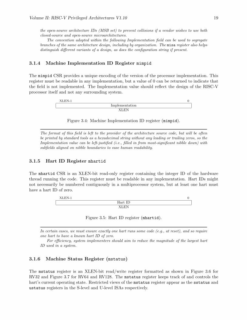
3.1.4 Machine Implementation ID Register mimpid
The mimpid CSR provides a unique encoding of the version of the processor implementation. Thisregister must be readable in any implementation, but a value of 0 can be returned to indicate thatthe field is not implemented. The Implementation value should reflect the design of the RISC-Vprocessor itself and not any surrounding system.
XLEN-1 0
Implementation
XLEN
Figure 3.4: Machine Implementation ID register (mimpid).
The format of this field is left to the provider of the architecture source code, but will be oftenbe printed by standard tools as a hexadecimal string without any leading or trailing zeros, so theImplementation value can be left-justified (i.e., filled in from most-significant nibble down) withsubfields aligned on nibble boundaries to ease human readability.
3.1.5 Hart ID Register mhartid
The mhartid CSR is an XLEN-bit read-only register containing the integer ID of the hardwarethread running the code. This register must be readable in any implementation. Hart IDs mightnot necessarily be numbered contiguously in a multiprocessor system, but at least one hart musthave a hart ID of zero.
XLEN-1 0
Hart ID
XLEN
Figure 3.5: Hart ID register (mhartid).
In certain cases, we must ensure exactly one hart runs some code (e.g., at reset), and so requireone hart to have a known hart ID of zero.
For efficiency, system implementers should aim to reduce the magnitude of the largest hartID used in a system.
3.1.6 Machine Status Register (mstatus)
The mstatus register is an XLEN-bit read/write register formatted as shown in Figure 3.6 forRV32 and Figure 3.7 for RV64 and RV128. The mstatus register keeps track of and controls thehart’s current operating state. Restricted views of the mstatus register appear as the sstatus andustatus registers in the S-level and U-level ISAs respectively.
20 Volume II: RISC-V Privileged Architectures V1.10
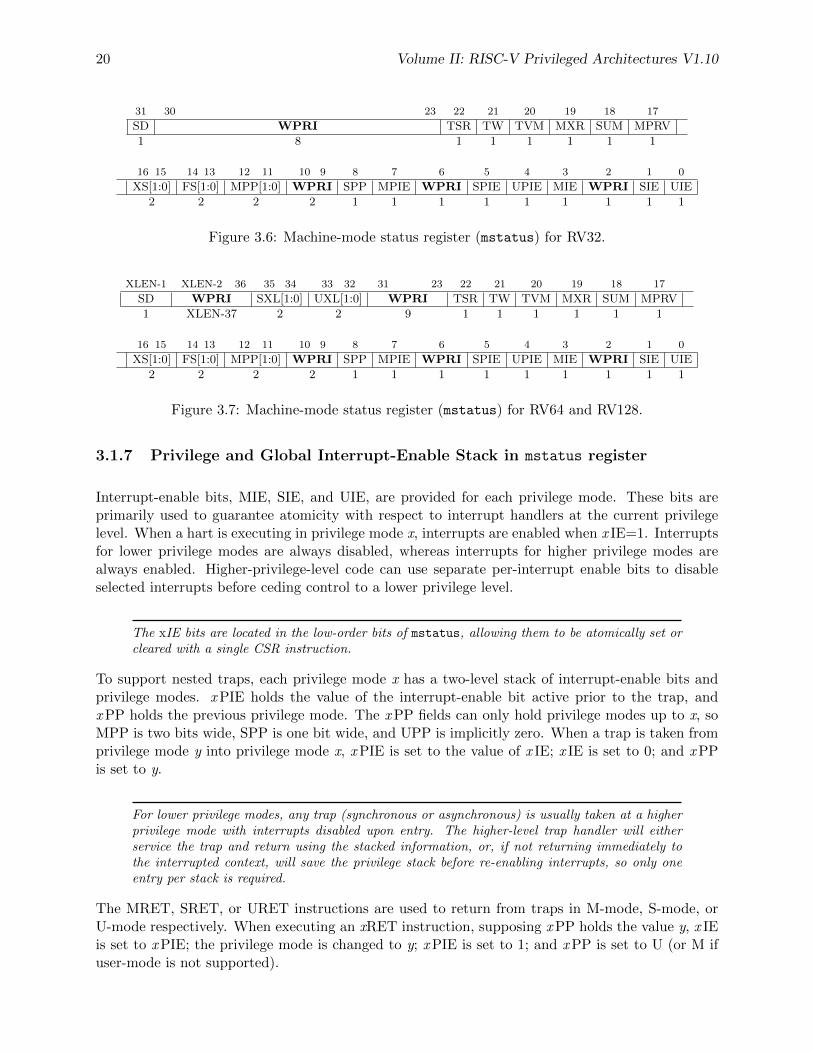
31 30 23 22 21 20 19 18 17
SD WPRI TSR TW TVM MXR SUM MPRV
1 8 1 1 1 1 1 1
16 15 14 13 12 11 10 9 8 7 6 5 4 3 2 1 0
XS[1:0] FS[1:0] MPP[1:0] WPRI SPP MPIE WPRI SPIE UPIE MIE WPRI SIE UIE
2 2 2 2 1 1 1 1 1 1 1 1 1
Figure 3.6: Machine-mode status register (mstatus) for RV32.
XLEN-1 XLEN-2 36 35 34 33 32 31 23 22 21 20 19 18 17
SD WPRI SXL[1:0] UXL[1:0] WPRI TSR TW TVM MXR SUM MPRV
1 XLEN-37 2 2 9 1 1 1 1 1 1
16 15 14 13 12 11 10 9 8 7 6 5 4 3 2 1 0
XS[1:0] FS[1:0] MPP[1:0] WPRI SPP MPIE WPRI SPIE UPIE MIE WPRI SIE UIE
2 2 2 2 1 1 1 1 1 1 1 1 1
Figure 3.7: Machine-mode status register (mstatus) for RV64 and RV128.
3.1.7 Privilege and Global Interrupt-Enable Stack in mstatus register
Interrupt-enable bits, MIE, SIE, and UIE, are provided for each privilege mode. These bits areprimarily used to guarantee atomicity with respect to interrupt handlers at the current privilegelevel. When a hart is executing in privilege mode x, interrupts are enabled when x IE=1. Interruptsfor lower privilege modes are always disabled, whereas interrupts for higher privilege modes arealways enabled. Higher-privilege-level code can use separate per-interrupt enable bits to disableselected interrupts before ceding control to a lower privilege level.
The xIE bits are located in the low-order bits of mstatus, allowing them to be atomically set orcleared with a single CSR instruction.
To support nested traps, each privilege mode x has a two-level stack of interrupt-enable bits andprivilege modes. x PIE holds the value of the interrupt-enable bit active prior to the trap, andx PP holds the previous privilege mode. The x PP fields can only hold privilege modes up to x, soMPP is two bits wide, SPP is one bit wide, and UPP is implicitly zero. When a trap is taken fromprivilege mode y into privilege mode x, x PIE is set to the value of x IE; x IE is set to 0; and x PPis set to y.
For lower privilege modes, any trap (synchronous or asynchronous) is usually taken at a higherprivilege mode with interrupts disabled upon entry. The higher-level trap handler will eitherservice the trap and return using the stacked information, or, if not returning immediately tothe interrupted context, will save the privilege stack before re-enabling interrupts, so only oneentry per stack is required.
The MRET, SRET, or URET instructions are used to return from traps in M-mode, S-mode, orU-mode respectively. When executing an xRET instruction, supposing x PP holds the value y, x IEis set to x PIE; the privilege mode is changed to y; x PIE is set to 1; and x PP is set to U (or M ifuser-mode is not supported).
Volume II: RISC-V Privileged Architectures V1.10 21
When the stack is popped, the lowest-supported privilege mode with interrupts enabled is addedto the bottom of stack to help catch errors that cause invalid entries to be popped off the stack.
x PP fields are WLRL fields that need only be able to store supported privilege modes, includingx and any implemented privilege mode lower than x.
If the machine provides only U and M modes, then only a single hardware storage bit is requiredto represent either 00 or 11 in MPP.
User-level interrupts are an optional extension and have been allocated the ISA extension letter N.If user-level interrupts are omitted, the UIE and UPIE bits are hardwired to zero. For all othersupported privilege modes x, the x IE and x PIE must not be hardwired.
User-level interrupts are primarily intended to support secure embedded systems with only M-mode and U-mode present, but can also be supported in systems running Unix-like operatingsystems to support user-level trap handling.
Fields that were previously allocated for H-mode support in mstatus have now been reserved asWPRI fields. To reduce backwards incompatibility with existing implementations, we did notcompact the register after removing these fields.
3.1.8 Base ISA Control in mstatus Register
For RV64 and RV128 systems, the SXL and UXL fields are WARL fields that control the value ofXLEN for S-mode and U-mode, respectively. The encoding of these fields is the same as the MXLfield of misa, shown in Table 3.1. The effective XLEN in S-mode and U-mode are termed S-XLENand U-XLEN, respectively.
For RV32 systems, the SXL and UXL fields do not exist, and S-XLEN = 32 and U-XLEN = 32.
For RV64 and RV128 systems, if S-mode is not supported, then SXL is hardwired to zero. Other-wise, it is a WARL field that encodes the current value of S-XLEN. In particular, the implemen-tation may hardwire SXL so that S-XLEN = M-XLEN.
For RV64 and RV128 systems, if U-mode is not supported, then UXL is hardwired to zero. Other-wise, it is a WARL field that encodes the current value of U-XLEN. In particular, the implemen-tation may hardwire UXL so that U-XLEN = M-XLEN.
Whenever XLEN in any mode is set to a value less than the widest supported XLEN, all operationsmust ignore source operand register bits above the configured XLEN, and must sign-extend resultsto fill the entire widest supported XLEN in the destination register.
To reduce hardware complexity, the architecture imposes no checks that lower-privilege modeshave XLEN settings less than or equal to the next-higher privilege mode. In practice, suchsettings would almost always be an error, but machine operation is well-defined even in thiscase.
22 Volume II: RISC-V Privileged Architectures V1.10
3.1.9 Memory Privilege in mstatus Register
The MPRV (Modify PRiVilege) bit modifies the privilege level at which loads and stores executein all privilege modes. When MPRV=0, translation and protection behave as normal. WhenMPRV=1, load and store memory addresses are translated and protected as though the currentprivilege mode were set to MPP. Instruction address-translation and protection are unaffected.MPRV is hardwired to 0 if U-mode is not supported.
The MXR (Make eXecutable Readable) bit modifies the privilege with which loads access virtualmemory. When MXR=0, only loads from pages marked readable (R=1 in Figure 4.15) will succeed.When MXR=1, loads from pages marked either readable or executable (R=1 or X=1) will succeed.MXR has no effect when page-based virtual memory is not in effect. MXR is hardwired to 0 ifS-mode is not supported.
The MPRV and MXR mechanisms were conceived to improve the efficiency of M-mode routinesthat emulate missing hardware features, e.g., misaligned loads and stores. MPRV obviates theneed to perform address translation in software. MXR allows instruction words to be loadedfrom pages marked execute-only.
For simplicity, MPRV and MXR are in effect regardless of privilege mode, but in normaluse will only be enabled for short sequences in machine mode.
The SUM (permit Supervisor User Memory access) bit modifies the privilege with which S-modeloads, stores, and instruction fetches access virtual memory. When SUM=0, S-mode memoryaccesses to pages that are accessible by U-mode (U=1 in Figure 4.15) will fault. When SUM=1,these accesses are permitted. SUM has no effect when page-based virtual memory is not in effect.Note that, while SUM is ordinarily ignored when not executing in S-mode, it is in effect whenMPRV=1 and MPP=S. SUM is hardwired to 0 if S-mode is not supported.
3.1.10 Virtualization Support in mstatus Register
The TVM (Trap Virtual Memory) bit supports intercepting supervisor virtual-memory man-agement operations. When TVM=1, attempts to read or write the satp CSR or execute theSFENCE.VMA instruction while executing in S-mode will raise an illegal instruction exception.When TVM=0, these operations are permitted in S-mode. TVM is hard-wired to 0 when S-modeis not supported.
The TVM mechanism improves virtualization efficiency by permitting guest operating systems toexecute in S-mode, rather than classically virtualizing them in U-mode. This approach obviatesthe need to trap accesses to most S-mode CSRs.
Trapping satp accesses and the SFENCE.VMA instruction provides the hooks necessary tolazily populate shadow page tables.
The TW (Timeout Wait) bit supports intercepting the WFI instruction (see Section 3.2.3). WhenTW=0, the WFI instruction is permitted in S-mode. When TW=1, if WFI is executed in S-mode, and it does not complete within an implementation-specific, bounded time limit, the WFIinstruction causes an illegal instruction trap. The time limit may always be 0, in which case WFIalways causes an illegal instruction trap in S-mode when TW=1. TW is hard-wired to 0 whenS-mode is not supported.
Volume II: RISC-V Privileged Architectures V1.10 23
Trapping the WFI instruction can trigger a world switch to another guest OS, rather thanwastefully idling in the current guest.
The TSR (Trap SRET) bit supports intercepting the supervisor exception return instruction, SRET.When TSR=1, attempts to execute SRET while executing in S-mode will raise an illegal instructionexception. When TSR=0, this operation is permitted in S-mode. TSR is hard-wired to 0 whenS-mode is not supported.
Trapping SRET is necessary to emulate the Augmented Virtualization mechanism (see Chap-ter 5) on implementations that do not provide it.
3.1.11 Extension Context Status in mstatus Register
Supporting substantial extensions is one of the primary goals of RISC-V, and hence we define astandard interface to allow unchanged privileged-mode code, particularly a supervisor-level OS, tosupport arbitrary user-mode state extensions.
To date, there are no standard extensions that define additional state beyond the floating-pointCSR and data registers.
The FS[1:0] read/write field and the XS[1:0] read-only field are used to reduce the cost of contextsave and restore by setting and tracking the current state of the floating-point unit and any otheruser-mode extensions respectively. The FS field encodes the status of the floating-point unit,including the CSR fcsr and floating-point data registers f0–f31, while the XS field encodes thestatus of additional user-mode extensions and associated state. These fields can be checked by acontext switch routine to quickly determine whether a state save or restore is required. If a save orrestore is required, additional instructions and CSRs are typically required to effect and optimizethe process.
The design anticipates that most context switches will not need to save/restore state in eitheror both of the floating-point unit or other extensions, so provides a fast check via the SD bit.
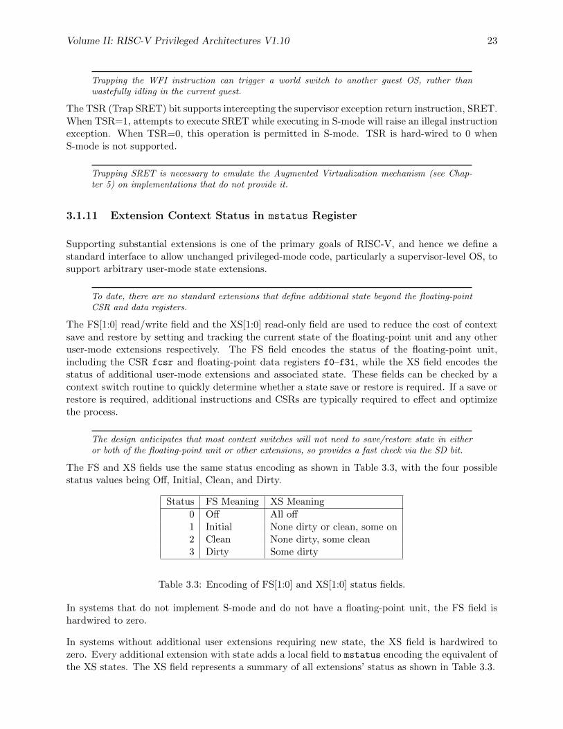
The FS and XS fields use the same status encoding as shown in Table 3.3, with the four possiblestatus values being Off, Initial, Clean, and Dirty.
Status FS Meaning XS Meaning
0 Off All off1 Initial None dirty or clean, some on2 Clean None dirty, some clean3 Dirty Some dirty
Table 3.3: Encoding of FS[1:0] and XS[1:0] status fields.
In systems that do not implement S-mode and do not have a floating-point unit, the FS field ishardwired to zero.
In systems without additional user extensions requiring new state, the XS field is hardwired tozero. Every additional extension with state adds a local field to mstatus encoding the equivalent ofthe XS states. The XS field represents a summary of all extensions’ status as shown in Table 3.3.
24 Volume II: RISC-V Privileged Architectures V1.10
The XS field effectively reports the maximum status value across all user-extension status fields,though individual extensions can use a different encoding than XS.
The SD bit is a read-only bit that summarizes whether either the FS field or XS field signals thepresence of some dirty state that will require saving extended user context to memory. If both XSand FS are hardwired to zero, then SD is also always zero.
When an extension’s status is set to Off, any instruction that attempts to read or write the corre-sponding state will cause an exception. When the status is Initial, the corresponding state shouldhave an initial constant value. When the status is Clean, the corresponding state is potentiallydifferent from the initial value, but matches the last value stored on a context swap. When thestatus is Dirty, the corresponding state has potentially been modified since the last context save.
During a context save, the responsible privileged code need only write out the corresponding stateif its status is Dirty, and can then reset the extension’s status to Clean. During a context restore,the context need only be loaded from memory if the status is Clean (it should never be Dirty atrestore). If the status is Initial, the context must be set to an initial constant value on contextrestore to avoid a security hole, but this can be done without accessing memory. For example, thefloating-point registers can all be initialized to the immediate value 0.
The FS and XS fields are read by the privileged code before saving the context. The FS field isset directly by privileged code when resuming a user context, while the XS field is set indirectly bywriting to the status register of the individual extensions. The status fields will also be updatedduring execution of instructions, regardless of privilege mode.
Extensions to the user-mode ISA often include additional user-mode state, and this state can beconsiderably larger than the base integer registers. The extensions might only be used for someapplications, or might only be needed for short phases within a single application. To improveperformance, the user-mode extension can define additional instructions to allow user-mode softwareto return the unit to an initial state or even to turn off the unit.
For example, a coprocessor might require to be configured before use and can be “unconfigured”after use. The unconfigured state would be represented as the Initial state for context save. If thesame application remains running between the unconfigure and the next configure (which wouldset status to Dirty), there is no need to actually reinitialize the state at the unconfigure instruction,as all state is local to the user process, i.e., the Initial state may only cause the coprocessor stateto be initialized to a constant value at context restore, not at every unconfigure.
Executing a user-mode instruction to disable a unit and place it into the Off state will cause anillegal instruction exception to be raised if any subsequent instruction tries to use the unit beforeit is turned back on. A user-mode instruction to turn a unit on must also ensure the unit’s state isproperly initialized, as the unit might have been used by another context meantime.
Changing the setting of FS has no effect on the contents of the floating-point register state. Inparticular, setting FS=Off does not destroy the state, nor does setting FS=Initial clear the contents.Other extensions might not preserve state when set to Off.
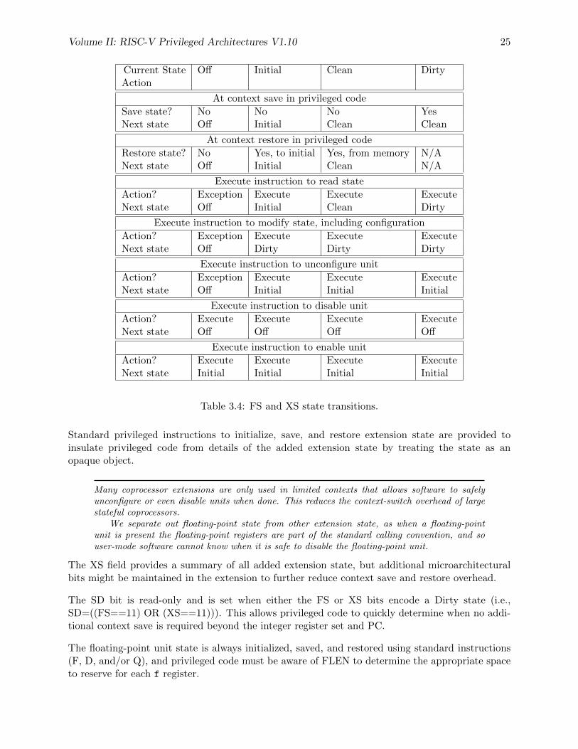
Table 3.4 shows all the possible state transitions for the FS or XS status bits. Note that the standardfloating-point extensions do not support user-mode unconfigure or disable/enable instructions.
Volume II: RISC-V Privileged Architectures V1.10 25
Current State Off Initial Clean DirtyAction
At context save in privileged code
Save state? No No No YesNext state Off Initial Clean Clean
At context restore in privileged code
Restore state? No Yes, to initial Yes, from memory N/ANext state Off Initial Clean N/A
Execute instruction to read state
Action? Exception Execute Execute ExecuteNext state Off Initial Clean Dirty
Execute instruction to modify state, including configuration
Action? Exception Execute Execute ExecuteNext state Off Dirty Dirty Dirty
Execute instruction to unconfigure unit
Action? Exception Execute Execute ExecuteNext state Off Initial Initial Initial
Execute instruction to disable unit
Action? Execute Execute Execute ExecuteNext state Off Off Off Off
Execute instruction to enable unit
Action? Execute Execute Execute ExecuteNext state Initial Initial Initial Initial
Table 3.4: FS and XS state transitions.
Standard privileged instructions to initialize, save, and restore extension state are provided toinsulate privileged code from details of the added extension state by treating the state as anopaque object.
Many coprocessor extensions are only used in limited contexts that allows software to safelyunconfigure or even disable units when done. This reduces the context-switch overhead of largestateful coprocessors.
We separate out floating-point state from other extension state, as when a floating-pointunit is present the floating-point registers are part of the standard calling convention, and souser-mode software cannot know when it is safe to disable the floating-point unit.
The XS field provides a summary of all added extension state, but additional microarchitecturalbits might be maintained in the extension to further reduce context save and restore overhead.
The SD bit is read-only and is set when either the FS or XS bits encode a Dirty state (i.e.,SD=((FS==11) OR (XS==11))). This allows privileged code to quickly determine when no addi-tional context save is required beyond the integer register set and PC.
The floating-point unit state is always initialized, saved, and restored using standard instructions(F, D, and/or Q), and privileged code must be aware of FLEN to determine the appropriate spaceto reserve for each f register.
26 Volume II: RISC-V Privileged Architectures V1.10
In a supervisor-level OS, any additional user-mode state should be initialized, saved, and re-stored using SBI calls that treats the additional context as an opaque object of a fixed maximumsize. The implementation of the SBI initialize, save, and restore calls might require additionalimplementation-dependent privileged instructions to initialize, save, and restore microarchitecturalstate inside a coprocessor.
All privileged modes share a single copy of the FS and XS bits. In a system with more than oneprivileged mode, supervisor mode would normally use the FS and XS bits directly to record thestatus with respect to the supervisor-level saved context. Other more-privileged active modes mustbe more conservative in saving and restoring the extension state in their corresponding version ofthe context.
In any reasonable use case, the number of context switches between user and supervisor levelshould far outweigh the number of context switches to other privilege levels. Note that coproces-sors should not require their context to be saved and restored to service asynchronous interrupts,unless the interrupt results in a user-level context swap.
3.1.12 Machine Trap-Vector Base-Address Register (mtvec)
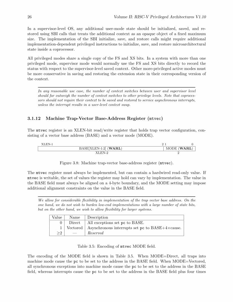
The mtvec register is an XLEN-bit read/write register that holds trap vector configuration, con-sisting of a vector base address (BASE) and a vector mode (MODE).
XLEN-1 2 1 0
BASE[XLEN-1:2] (WARL) MODE (WARL)
XLEN-2 2
Figure 3.8: Machine trap-vector base-address register (mtvec).
The mtvec register must always be implemented, but can contain a hardwired read-only value. Ifmtvec is writable, the set of values the register may hold can vary by implementation. The value inthe BASE field must always be aligned on a 4-byte boundary, and the MODE setting may imposeadditional alignment constraints on the value in the BASE field.
We allow for considerable flexibility in implementation of the trap vector base address. On theone hand, we do not wish to burden low-end implementations with a large number of state bits,but on the other hand, we wish to allow flexibility for larger systems.
Value Name Description
0 Direct All exceptions set pc to BASE.1 Vectored Asynchronous interrupts set pc to BASE+4×cause.≥2 — Reserved
Table 3.5: Encoding of mtvec MODE field.
The encoding of the MODE field is shown in Table 3.5. When MODE=Direct, all traps intomachine mode cause the pc to be set to the address in the BASE field. When MODE=Vectored,all synchronous exceptions into machine mode cause the pc to be set to the address in the BASEfield, whereas interrupts cause the pc to be set to the address in the BASE field plus four times
Volume II: RISC-V Privileged Architectures V1.10 27
the interrupt cause number. For example, a machine-mode timer interrupt (see Table 3.6) causesthe pc to be set to BASE+0x1c. Setting MODE=Vectored may impose an additional alignmentconstraint on BASE, requiring up to 4×XLEN -byte alignment.
When vectored interrupts are enabled, interrupt cause 0, which corresponds to user-mode soft-ware interrupts, are vectored to the same location as synchronous exceptions. This ambiguitydoes not arise in practice, since user-mode software interrupts are either disabled or delegatedto a less-privileged mode.
Reset and NMI vector locations are given in a platform specification.
3.1.13 Machine Trap Delegation Registers (medeleg and mideleg)
By default, all traps at any privilege level are handled in machine mode, though a machine-modehandler can redirect traps back to the appropriate level with the MRET instruction (Section 3.2.2).To increase performance, implementations can provide individual read/write bits within medeleg
and mideleg to indicate that certain exceptions and interrupts should be processed directly by alower privilege level. The machine exception delegation register (medeleg) and machine interruptdelegation register (mideleg) are XLEN-bit read/write registers.
In systems with all three privilege modes (M/S/U), setting a bit in medeleg or mideleg willdelegate the corresponding trap in S-mode or U-mode to the S-mode trap handler. If U-mode trapsare supported, S-mode may in turn set corresponding bits in the sedeleg and sideleg registersto delegate traps that occur in U-mode to the U-mode trap handler.
In systems with two privilege modes (M/U) and support for U-mode traps, setting a bit in medeleg
or mideleg will delegate the corresponding trap in U-mode to the U-mode trap handler.
In systems with only M-mode, or with both M-mode and U-mode but without U-mode trap support,the medeleg and mideleg registers should not exist.
In versions 1.9.1 and earlier , these registers existed but were hardwired to zero in M-mode only,or M/U without N systems. There is no reason to require they return zero in those cases, as themisa register indicates whether they exist.
When a trap is delegated to a less-privileged mode x, the x cause register is written with the trapcause; the x epc register is written with the virtual address of the instruction that took the trap;the x PP field of mstatus is written with the active privilege mode at the time of the trap; thex PIE field of mstatus is written with the value of the active interrupt-enable bit at the time of thetrap; and the x IE field of mstatus is cleared. The mcause and mepc registers and the MPP andMPIE fields of mstatus are not written.
An implementation shall not hardwire any delegation bits to one, i.e., any trap that can be delegatedmust support not being delegated. An implementation can choose to subset the delegatable traps,with the supported delegatable bits found by writing one to every bit location, then reading backthe value in medeleg or mideleg to see which bit positions hold a one.
Traps never transition from a more-privileged mode to a less-privileged mode. For example, ifM-mode has delegated illegal instruction traps to S-mode, and M-mode software later executes
28 Volume II: RISC-V Privileged Architectures V1.10
an illegal instruction, the trap is taken in M-mode, rather than being delegated to S-mode. Bycontrast, traps may be taken horizontally. Using the same example, if M-mode has delegated illegalinstruction traps to S-mode, and S-mode software later executes an illegal instruction, the trap istaken in S-mode.
XLEN-1 0
Synchronous Exceptions (WARL)
XLEN
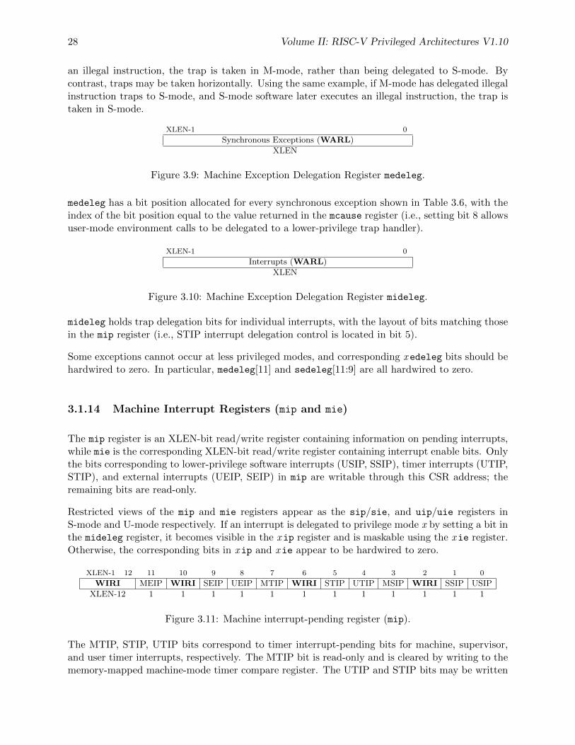
Figure 3.9: Machine Exception Delegation Register medeleg.
medeleg has a bit position allocated for every synchronous exception shown in Table 3.6, with theindex of the bit position equal to the value returned in the mcause register (i.e., setting bit 8 allowsuser-mode environment calls to be delegated to a lower-privilege trap handler).
XLEN-1 0
Interrupts (WARL)
XLEN
Figure 3.10: Machine Exception Delegation Register mideleg.
mideleg holds trap delegation bits for individual interrupts, with the layout of bits matching thosein the mip register (i.e., STIP interrupt delegation control is located in bit 5).
Some exceptions cannot occur at less privileged modes, and corresponding x edeleg bits should behardwired to zero. In particular, medeleg[11] and sedeleg[11:9] are all hardwired to zero.
3.1.14 Machine Interrupt Registers (mip and mie)
The mip register is an XLEN-bit read/write register containing information on pending interrupts,while mie is the corresponding XLEN-bit read/write register containing interrupt enable bits. Onlythe bits corresponding to lower-privilege software interrupts (USIP, SSIP), timer interrupts (UTIP,STIP), and external interrupts (UEIP, SEIP) in mip are writable through this CSR address; theremaining bits are read-only.
Restricted views of the mip and mie registers appear as the sip/sie, and uip/uie registers inS-mode and U-mode respectively. If an interrupt is delegated to privilege mode x by setting a bit inthe mideleg register, it becomes visible in the x ip register and is maskable using the x ie register.Otherwise, the corresponding bits in x ip and x ie appear to be hardwired to zero.
XLEN-1 12 11 10 9 8 7 6 5 4 3 2 1 0
WIRI MEIP WIRI SEIP UEIP MTIP WIRI STIP UTIP MSIP WIRI SSIP USIP
XLEN-12 1 1 1 1 1 1 1 1 1 1 1 1
Figure 3.11: Machine interrupt-pending register (mip).
The MTIP, STIP, UTIP bits correspond to timer interrupt-pending bits for machine, supervisor,and user timer interrupts, respectively. The MTIP bit is read-only and is cleared by writing to thememory-mapped machine-mode timer compare register. The UTIP and STIP bits may be written
Volume II: RISC-V Privileged Architectures V1.10 29
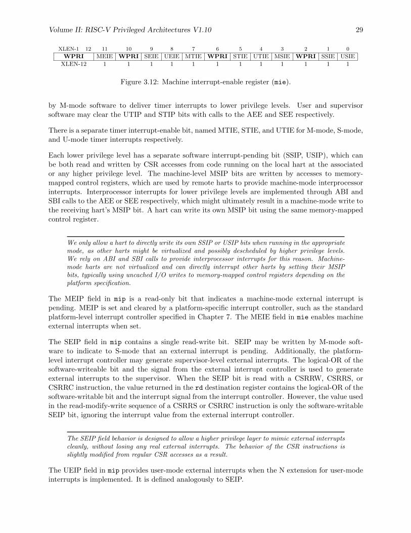
XLEN-1 12 11 10 9 8 7 6 5 4 3 2 1 0
WPRI MEIE WPRI SEIE UEIE MTIE WPRI STIE UTIE MSIE WPRI SSIE USIE
XLEN-12 1 1 1 1 1 1 1 1 1 1 1 1
Figure 3.12: Machine interrupt-enable register (mie).
by M-mode software to deliver timer interrupts to lower privilege levels. User and supervisorsoftware may clear the UTIP and STIP bits with calls to the AEE and SEE respectively.
There is a separate timer interrupt-enable bit, named MTIE, STIE, and UTIE for M-mode, S-mode,and U-mode timer interrupts respectively.
Each lower privilege level has a separate software interrupt-pending bit (SSIP, USIP), which canbe both read and written by CSR accesses from code running on the local hart at the associatedor any higher privilege level. The machine-level MSIP bits are written by accesses to memory-mapped control registers, which are used by remote harts to provide machine-mode interprocessorinterrupts. Interprocessor interrupts for lower privilege levels are implemented through ABI andSBI calls to the AEE or SEE respectively, which might ultimately result in a machine-mode write tothe receiving hart’s MSIP bit. A hart can write its own MSIP bit using the same memory-mappedcontrol register.
We only allow a hart to directly write its own SSIP or USIP bits when running in the appropriatemode, as other harts might be virtualized and possibly descheduled by higher privilege levels.We rely on ABI and SBI calls to provide interprocessor interrupts for this reason. Machine-mode harts are not virtualized and can directly interrupt other harts by setting their MSIPbits, typically using uncached I/O writes to memory-mapped control registers depending on theplatform specification.
The MEIP field in mip is a read-only bit that indicates a machine-mode external interrupt ispending. MEIP is set and cleared by a platform-specific interrupt controller, such as the standardplatform-level interrupt controller specified in Chapter 7. The MEIE field in mie enables machineexternal interrupts when set.
The SEIP field in mip contains a single read-write bit. SEIP may be written by M-mode soft-ware to indicate to S-mode that an external interrupt is pending. Additionally, the platform-level interrupt controller may generate supervisor-level external interrupts. The logical-OR of thesoftware-writeable bit and the signal from the external interrupt controller is used to generateexternal interrupts to the supervisor. When the SEIP bit is read with a CSRRW, CSRRS, orCSRRC instruction, the value returned in the rd destination register contains the logical-OR of thesoftware-writable bit and the interrupt signal from the interrupt controller. However, the value usedin the read-modify-write sequence of a CSRRS or CSRRC instruction is only the software-writableSEIP bit, ignoring the interrupt value from the external interrupt controller.
The SEIP field behavior is designed to allow a higher privilege layer to mimic external interruptscleanly, without losing any real external interrupts. The behavior of the CSR instructions isslightly modified from regular CSR accesses as a result.
The UEIP field in mip provides user-mode external interrupts when the N extension for user-modeinterrupts is implemented. It is defined analogously to SEIP.
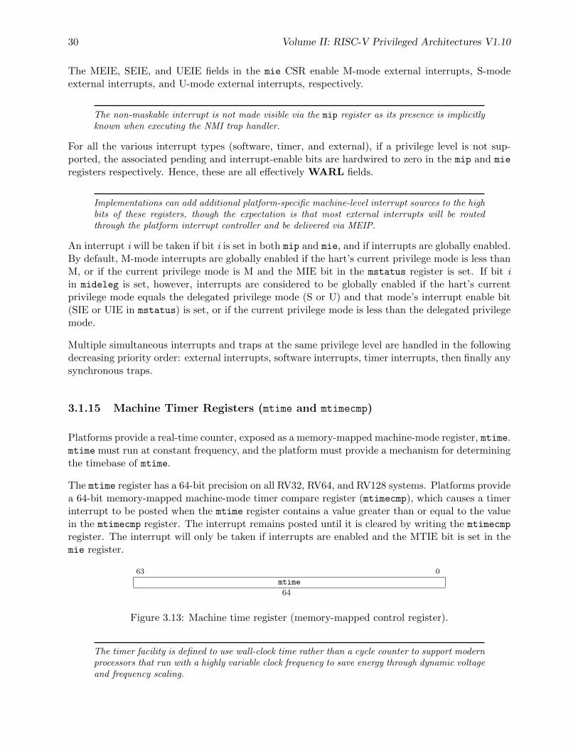
30 Volume II: RISC-V Privileged Architectures V1.10
The MEIE, SEIE, and UEIE fields in the mie CSR enable M-mode external interrupts, S-modeexternal interrupts, and U-mode external interrupts, respectively.
The non-maskable interrupt is not made visible via the mip register as its presence is implicitlyknown when executing the NMI trap handler.
For all the various interrupt types (software, timer, and external), if a privilege level is not sup-ported, the associated pending and interrupt-enable bits are hardwired to zero in the mip and mie
registers respectively. Hence, these are all effectively WARL fields.
Implementations can add additional platform-specific machine-level interrupt sources to the highbits of these registers, though the expectation is that most external interrupts will be routedthrough the platform interrupt controller and be delivered via MEIP.
An interrupt i will be taken if bit i is set in both mip and mie, and if interrupts are globally enabled.By default, M-mode interrupts are globally enabled if the hart’s current privilege mode is less thanM, or if the current privilege mode is M and the MIE bit in the mstatus register is set. If bit iin mideleg is set, however, interrupts are considered to be globally enabled if the hart’s currentprivilege mode equals the delegated privilege mode (S or U) and that mode’s interrupt enable bit(SIE or UIE in mstatus) is set, or if the current privilege mode is less than the delegated privilegemode.
Multiple simultaneous interrupts and traps at the same privilege level are handled in the followingdecreasing priority order: external interrupts, software interrupts, timer interrupts, then finally anysynchronous traps.
3.1.15 Machine Timer Registers (mtime and mtimecmp)
Platforms provide a real-time counter, exposed as a memory-mapped machine-mode register, mtime.mtime must run at constant frequency, and the platform must provide a mechanism for determiningthe timebase of mtime.
The mtime register has a 64-bit precision on all RV32, RV64, and RV128 systems. Platforms providea 64-bit memory-mapped machine-mode timer compare register (mtimecmp), which causes a timerinterrupt to be posted when the mtime register contains a value greater than or equal to the valuein the mtimecmp register. The interrupt remains posted until it is cleared by writing the mtimecmp
register. The interrupt will only be taken if interrupts are enabled and the MTIE bit is set in themie register.
63 0
mtime
64
Figure 3.13: Machine time register (memory-mapped control register).
The timer facility is defined to use wall-clock time rather than a cycle counter to support modernprocessors that run with a highly variable clock frequency to save energy through dynamic voltageand frequency scaling.
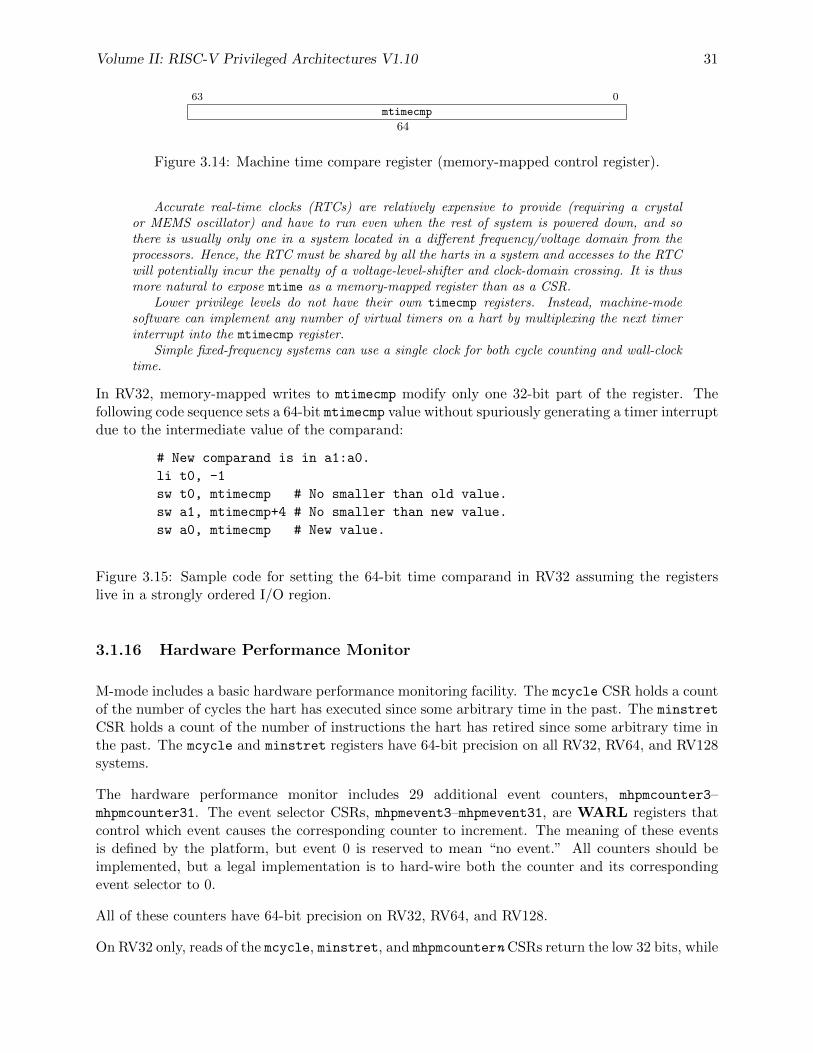
Volume II: RISC-V Privileged Architectures V1.10 31
63 0
mtimecmp
64
Figure 3.14: Machine time compare register (memory-mapped control register).
Accurate real-time clocks (RTCs) are relatively expensive to provide (requiring a crystalor MEMS oscillator) and have to run even when the rest of system is powered down, and sothere is usually only one in a system located in a different frequency/voltage domain from theprocessors. Hence, the RTC must be shared by all the harts in a system and accesses to the RTCwill potentially incur the penalty of a voltage-level-shifter and clock-domain crossing. It is thusmore natural to expose mtime as a memory-mapped register than as a CSR.
Lower privilege levels do not have their own timecmp registers. Instead, machine-modesoftware can implement any number of virtual timers on a hart by multiplexing the next timerinterrupt into the mtimecmp register.
Simple fixed-frequency systems can use a single clock for both cycle counting and wall-clocktime.
In RV32, memory-mapped writes to mtimecmp modify only one 32-bit part of the register. Thefollowing code sequence sets a 64-bit mtimecmp value without spuriously generating a timer interruptdue to the intermediate value of the comparand:
# New comparand is in a1:a0.
li t0, -1
sw t0, mtimecmp # No smaller than old value.
sw a1, mtimecmp+4 # No smaller than new value.
sw a0, mtimecmp # New value.
Figure 3.15: Sample code for setting the 64-bit time comparand in RV32 assuming the registerslive in a strongly ordered I/O region.
3.1.16 Hardware Performance Monitor
M-mode includes a basic hardware performance monitoring facility. The mcycle CSR holds a countof the number of cycles the hart has executed since some arbitrary time in the past. The minstret
CSR holds a count of the number of instructions the hart has retired since some arbitrary time inthe past. The mcycle and minstret registers have 64-bit precision on all RV32, RV64, and RV128systems.
The hardware performance monitor includes 29 additional event counters, mhpmcounter3–mhpmcounter31. The event selector CSRs, mhpmevent3–mhpmevent31, are WARL registers thatcontrol which event causes the corresponding counter to increment. The meaning of these eventsis defined by the platform, but event 0 is reserved to mean “no event.” All counters should beimplemented, but a legal implementation is to hard-wire both the counter and its correspondingevent selector to 0.
All of these counters have 64-bit precision on RV32, RV64, and RV128.
On RV32 only, reads of the mcycle, minstret, and mhpmcountern CSRs return the low 32 bits, while
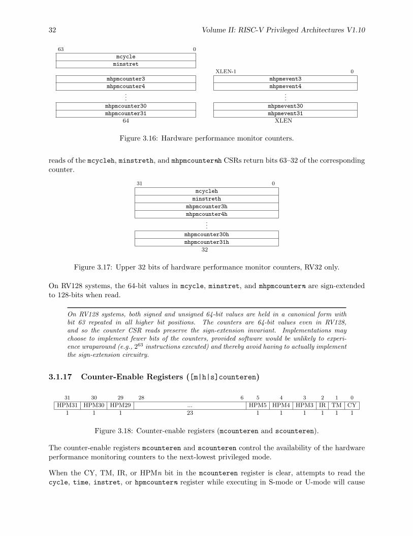
32 Volume II: RISC-V Privileged Architectures V1.10
63 0
mcycle
minstret
XLEN-1 0
mhpmcounter3 mhpmevent3
mhpmcounter4 mhpmevent4...
...mhpmcounter30 mhpmevent30
mhpmcounter31 mhpmevent31
64 XLEN
Figure 3.16: Hardware performance monitor counters.
reads of the mcycleh, minstreth, and mhpmcounternh CSRs return bits 63–32 of the correspondingcounter.
31 0
mcycleh
minstreth
mhpmcounter3h
mhpmcounter4h
...
mhpmcounter30h
mhpmcounter31h
32
Figure 3.17: Upper 32 bits of hardware performance monitor counters, RV32 only.
On RV128 systems, the 64-bit values in mcycle, minstret, and mhpmcountern are sign-extendedto 128-bits when read.
On RV128 systems, both signed and unsigned 64-bit values are held in a canonical form withbit 63 repeated in all higher bit positions. The counters are 64-bit values even in RV128,and so the counter CSR reads preserve the sign-extension invariant. Implementations maychoose to implement fewer bits of the counters, provided software would be unlikely to experi-ence wraparound (e.g., 263 instructions executed) and thereby avoid having to actually implementthe sign-extension circuitry.
3.1.17 Counter-Enable Registers ([m|h|s]counteren)
31 30 29 28 6 5 4 3 2 1 0
HPM31 HPM30 HPM29 ... HPM5 HPM4 HPM3 IR TM CY
1 1 1 23 1 1 1 1 1 1
Figure 3.18: Counter-enable registers (mcounteren and scounteren).
The counter-enable registers mcounteren and scounteren control the availability of the hardwareperformance monitoring counters to the next-lowest privileged mode.
When the CY, TM, IR, or HPMn bit in the mcounteren register is clear, attempts to read thecycle, time, instret, or hpmcountern register while executing in S-mode or U-mode will cause
Volume II: RISC-V Privileged Architectures V1.10 33
an illegal instruction exception. When one of these bits is set, access to the corresponding registeris permitted in the next implemented privilege mode (S-mode if implemented, otherwise U-mode).
If S-mode is implemented, the same bit positions in the scounteren register analogously controlaccess to these registers while executing in U-mode. If S-mode is permitted to access a counterregister and the corresponding bit is set in scounteren, then U-mode is also permitted to accessthat register.
Registers mcounteren and scounteren are WARL registers that must be implemented if U-modeand S-mode are implemented, Any of the bits may contain a hardwired value of zero, indicatingreads to the corresponding counter will cause an exception when executing in a less-privilegedmode.
The counter-enable bits support two common use cases with minimal hardware. For systems thatdo not need high-performance timers and counters, machine-mode software can trap accesses andimplement all features in software. For systems that need high-performance timers and countersbut are not concerned with obfuscating the underlying hardware counters, the counters can bedirectly exposed to lower privilege modes.
The cycle, instret, and hpmcountern CSRs are read-only shadows of mcycle, minstret, andmhpmcountern, respectively. The time CSR is a read-only shadow of the memory-mapped mtime
register.
Implementations can convert reads of the time CSR into loads to the memory-mapped mtime
register, or hard-wire the TM bits in mxcounteren to 0 and emulate this functionality in M-modesoftware.
3.1.18 Machine Scratch Register (mscratch)
The mscratch register is an XLEN-bit read/write register dedicated for use by machine mode.Typically, it is used to hold a pointer to a machine-mode hart-local context space and swappedwith a user register upon entry to an M-mode trap handler.
XLEN-1 0
mscratch
XLEN
Figure 3.19: Machine-mode scratch register.
The MIPS ISA allocated two user registers (k0/k1) for use by the operating system. Althoughthe MIPS scheme provides a fast and simple implementation, it also reduces available userregisters, and does not scale to further privilege levels, or nested traps. It can also require bothregisters are cleared before returning to user level to avoid a potential security hole and to providedeterministic debugging behavior.
The RISC-V user ISA was designed to support many possible privileged system environmentsand so we did not want to infect the user-level ISA with any OS-dependent features. The RISC-V CSR swap instructions can quickly save/restore values to the mscratch register. Unlike theMIPS design, the OS can rely on holding a value in the mscratch register while the user contextis running.
34 Volume II: RISC-V Privileged Architectures V1.10
3.1.19 Machine Exception Program Counter (mepc)
mepc is an XLEN-bit read/write register formatted as shown in Figure 3.20. The low bit of mepc(mepc[0]) is always zero. On implementations that do not support instruction-set extensions with16-bit instruction alignment, the two low bits (mepc[1:0]) are always zero.
The mepc register can never hold a PC value that would cause an instruction-address-misalignedexception.
mepc is a WARL register that must be able to hold all valid physical and virtual addresses. Itneed not be capable of holding all possible invalid addresses. Implementations may convert someinvalid address patterns into other invalid addresses prior to writing them to mepc.
When a trap is taken into M-mode, mepc is written with the virtual address of the instruction thatencountered the exception. Otherwise, mepc is never written by the implementation, though it maybe explicitly written by software.
XLEN-1 0
mepc
XLEN
Figure 3.20: Machine exception program counter register.
3.1.20 Machine Cause Register (mcause)
The mcause register is an XLEN-bit read-write register formatted as shown in Figure 3.21. When atrap is taken into M-mode, mcause is written with a code indicating the event that caused the trap.Otherwise, mcause is never written by the implementation, though it may be explicitly written bysoftware.
The Interrupt bit in the mcause register is set if the trap was caused by an interrupt. The ExceptionCode field contains a code identifying the last exception. Table 3.6 lists the possible machine-levelexception codes. The Exception Code is an WLRL field, so is only guaranteed to hold supportedexception codes.
XLEN-1 XLEN-2 0
Interrupt Exception Code (WLRL)
1 XLEN-1
Figure 3.21: Machine Cause register mcause.
We do not distinguish privileged instruction exceptions from illegal opcode exceptions. This sim-plifies the architecture and also hides details of which higher-privilege instructions are supportedby an implementation. The privilege level servicing the trap can implement a policy on whetherthese need to be distinguished, and if so, whether a given opcode should be treated as illegal orprivileged.
Interrupts can be separated from other traps with a single branch on the sign of the mcause
register value. A shift left can remove the interrupt bit and scale the exception codes to indexinto a trap vector table.
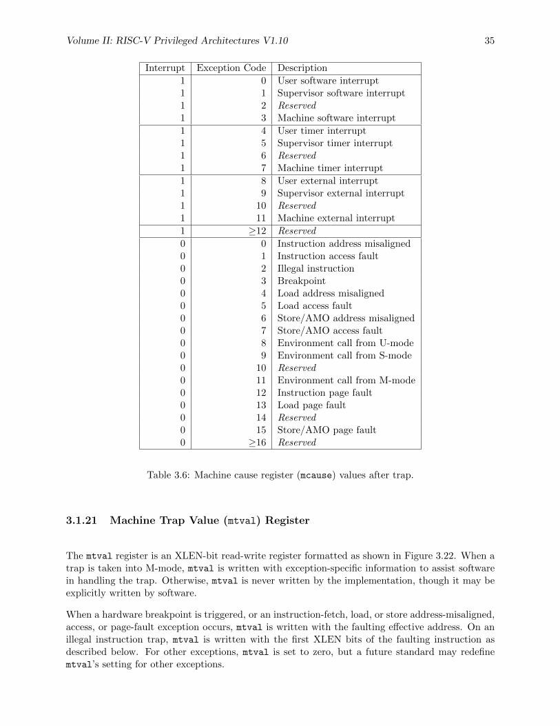
Volume II: RISC-V Privileged Architectures V1.10 35
Interrupt Exception Code Description
1 0 User software interrupt1 1 Supervisor software interrupt1 2 Reserved1 3 Machine software interrupt
1 4 User timer interrupt1 5 Supervisor timer interrupt1 6 Reserved1 7 Machine timer interrupt
1 8 User external interrupt1 9 Supervisor external interrupt1 10 Reserved1 11 Machine external interrupt
1 ≥12 Reserved
0 0 Instruction address misaligned0 1 Instruction access fault0 2 Illegal instruction0 3 Breakpoint0 4 Load address misaligned0 5 Load access fault0 6 Store/AMO address misaligned0 7 Store/AMO access fault0 8 Environment call from U-mode0 9 Environment call from S-mode0 10 Reserved0 11 Environment call from M-mode0 12 Instruction page fault0 13 Load page fault0 14 Reserved0 15 Store/AMO page fault0 ≥16 Reserved
Table 3.6: Machine cause register (mcause) values after trap.
3.1.21 Machine Trap Value (mtval) Register
The mtval register is an XLEN-bit read-write register formatted as shown in Figure 3.22. When atrap is taken into M-mode, mtval is written with exception-specific information to assist softwarein handling the trap. Otherwise, mtval is never written by the implementation, though it may beexplicitly written by software.
When a hardware breakpoint is triggered, or an instruction-fetch, load, or store address-misaligned,access, or page-fault exception occurs, mtval is written with the faulting effective address. On anillegal instruction trap, mtval is written with the first XLEN bits of the faulting instruction asdescribed below. For other exceptions, mtval is set to zero, but a future standard may redefinemtval’s setting for other exceptions.
36 Volume II: RISC-V Privileged Architectures V1.10
The mtval register replaces the mbadaddr register in the previous specification. In additionto providing bad addresses, the register can now provide the bad instruction that triggered anillegal instruction trap (and may in future be used to return other information). Returning theinstruction bits accelerates instruction emulation and also removes some races that might bepresent when trying to emulate illegal instructions.
When page-based virtual memory is enabled, mtval is written with the faulting virtual address,even for physical-memory access exceptions. This design reduces datapath cost for most imple-mentations, particularly those with hardware page-table walkers.
XLEN-1 0
mtval
XLEN
Figure 3.22: Machine Trap Value register.
For instruction-fetch access faults on RISC-V systems with variable-length instructions, mtval willcontain a pointer to the portion of the instruction that caused the fault while mepc will point tothe beginning of the instruction.
The mtval register can optionally also be used to return the faulting instruction bits on an illegalinstruction exception (mepc points to the faulting instruction in memory).
If this feature is not provided, then mtval is set to zero on an illegal instruction fault.
If the feature is provided, after an illegal instruction trap, mtval will contain the entire faultinginstruction provided the instruction is no longer than XLEN bits. If the instruction is less thanXLEN bits long, the upper bits of mtval are cleared to zero. If the instruction is more than XLENbits long, mtval will contain the first XLEN bits of the instruction.
Capturing the faulting instruction in mtval reduces the overhead of instruction emulation, po-tentially avoiding several partial instruction loads if the instruction is misaligned, and likely datacache misses or slow uncached accesses when loads are used to fetch the instruction into a dataregister. There is also a problem of atomicity if another agent is manipulating the instructionmemory, as might occur in a dynamic translation system.
A requirement is that the entire instruction (or at least the first XLEN bits) are fetched intomtval before taking the trap. This should not constrain implementations, which would typicallyfetch the entire instruction before attempting to decode the instruction, and avoids complicatingsoftware handlers.
A value of zero in mtval signifies either that the feature is not supported, or an illegal zeroinstruction was fetched. A load from the instruction memory pointed to by mepc can be usedto distinguish these two cases (or alternatively, the system configuration information can beinterrogated to install the appropriate trap handling before runtime).
mtval is a WARL register that must be able to hold all valid physical and virtual addresses andthe value 0. It need not be capable of holding all possible invalid addresses. Implementations mayconvert some invalid address patterns into other invalid addresses prior to writing them to mtval.If the feature to return the faulting instruction bits is implemented, mtval must also be able to holdall values less than 2N , where N is the smaller of XLEN and the width of the longest supportedinstruction.
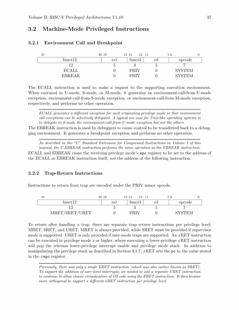
Volume II: RISC-V Privileged Architectures V1.10 37
3.2 Machine-Mode Privileged Instructions
3.2.1 Environment Call and Breakpoint
31 20 19 15 14 12 11 7 6 0
funct12 rs1 funct3 rd opcode
12 5 3 5 7ECALL 0 PRIV 0 SYSTEM
EBREAK 0 PRIV 0 SYSTEM
The ECALL instruction is used to make a request to the supporting execution environment.When executed in U-mode, S-mode, or M-mode, it generates an environment-call-from-U-modeexception, environment-call-from-S-mode exception, or environment-call-from-M-mode exception,respectively, and performs no other operation.
ECALL generates a different exception for each originating privilege mode so that environmentcall exceptions can be selectively delegated. A typical use case for Unix-like operating systems isto delegate to S-mode the environment-call-from-U-mode exception but not the others.
The EBREAK instruction is used by debuggers to cause control to be transferred back to a debug-ging environment. It generates a breakpoint exception and performs no other operation.
As described in the “C” Standard Extension for Compressed Instructions in Volume I of thismanual, the C.EBREAK instruction performs the same operation as the EBREAK instruction.
ECALL and EBREAK cause the receiving privilege mode’s epc register to be set to the address ofthe ECALL or EBREAK instruction itself, not the address of the following instruction.
3.2.2 Trap-Return Instructions
Instructions to return from trap are encoded under the PRIV minor opcode.
31 20 19 15 14 12 11 7 6 0
funct12 rs1 funct3 rd opcode
12 5 3 5 7MRET/SRET/URET 0 PRIV 0 SYSTEM
To return after handling a trap, there are separate trap return instructions per privilege level:MRET, SRET, and URET. MRET is always provided, while SRET must be provided if supervisormode is supported. URET is only provided if user-mode traps are supported. An x RET instructioncan be executed in privilege mode x or higher, where executing a lower-privilege x RET instructionwill pop the relevant lower-privilege interrupt enable and privilege mode stack. In addition tomanipulating the privilege stack as described in Section 3.1.7, x RET sets the pc to the value storedin the x epc register.
Previously, there was only a single ERET instruction (which was also earlier known as SRET).To support the addition of user-level interrupts, we needed to add a separate URET instructionto continue to allow classic virtualization of OS code using the ERET instruction. It then becamemore orthogonal to support a different xRET instruction per privilege level.
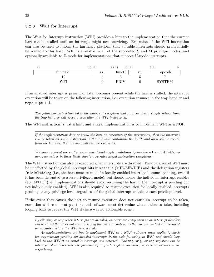
38 Volume II: RISC-V Privileged Architectures V1.10
3.2.3 Wait for Interrupt
The Wait for Interrupt instruction (WFI) provides a hint to the implementation that the currenthart can be stalled until an interrupt might need servicing. Execution of the WFI instructioncan also be used to inform the hardware platform that suitable interrupts should preferentiallybe routed to this hart. WFI is available in all of the supported S and M privilege modes, andoptionally available to U-mode for implementations that support U-mode interrupts.
31 20 19 15 14 12 11 7 6 0
funct12 rs1 funct3 rd opcode
12 5 3 5 7WFI 0 PRIV 0 SYSTEM
If an enabled interrupt is present or later becomes present while the hart is stalled, the interruptexception will be taken on the following instruction, i.e., execution resumes in the trap handler andmepc = pc + 4.
The following instruction takes the interrupt exception and trap, so that a simple return fromthe trap handler will execute code after the WFI instruction.
The WFI instruction is just a hint, and a legal implementation is to implement WFI as a NOP.
If the implementation does not stall the hart on execution of the instruction, then the interruptwill be taken on some instruction in the idle loop containing the WFI, and on a simple returnfrom the handler, the idle loop will resume execution.
We have removed the earlier requirement that implementations ignore the rs1 and rd fields, sonon-zero values in these fields should now raise illegal instruction exceptions.
The WFI instruction can also be executed when interrupts are disabled. The operation of WFI mustbe unaffected by the global interrupt bits in mstatus (MIE/SIE/UIE) and the delegation registers[m|s|u]ideleg (i.e., the hart must resume if a locally enabled interrupt becomes pending, even ifit has been delegated to a less-privileged mode), but should honor the individual interrupt enables(e.g, MTIE) (i.e., implementations should avoid resuming the hart if the interrupt is pending butnot individually enabled). WFI is also required to resume execution for locally enabled interruptspending at any privilege level, regardless of the global interrupt enable at each privilege level.
If the event that causes the hart to resume execution does not cause an interrupt to be taken,execution will resume at pc + 4, and software must determine what action to take, includinglooping back to repeat the WFI if there was no actionable event.
By allowing wakeup when interrupts are disabled, an alternate entry point to an interrupt handlercan be called that does not require saving the current context, as the current context can be savedor discarded before the WFI is executed.
As implementations are free to implement WFI as a NOP, software must explicitly checkfor any relevant pending but disabled interrupts in the code following an WFI, and should loopback to the WFI if no suitable interrupt was detected. The mip, sip, or uip registers can beinterrogated to determine the presence of any interrupt in machine, supervisor, or user moderespectively.
Volume II: RISC-V Privileged Architectures V1.10 39
The operation of WFI is unaffected by the delegation register settings.WFI is defined so that an implementation can trap into a higher privilege mode, either im-
mediately on encountering the WFI or after some interval to initiate a machine-mode transitionto a lower power state, for example.
The same “wait-for-event” template might be used for possible future extensions that wait onmemory locations changing, or message arrival.
3.3 Reset
Upon reset, a hart’s privilege mode is set to M. The mstatus fields MIE and MPRV are reset to0. The pc is set to an implementation-defined reset vector. The mcause register is set to a valueindicating the cause of the reset. All other hart state is undefined.
The mcause values after reset have implementation-specific interpretation, but the value 0 shouldbe returned on implementations that do not distinguish different reset conditions. Implementationsthat distinguish different reset conditions should only use 0 to indicate the most complete reset(e.g., hard reset).
Some designs may have multiple causes of reset (e.g., power-on reset, external hard reset,brownout detected, watchdog timer elapse, sleep-mode wakeup), which machine-mode softwareand debuggers may wish to distinguish.
mcause reset values may alias mcause values following synchronous exceptions. There is noambiguity in this overlap, since on reset the pc is set to a different value than on other traps.
3.4 Non-Maskable Interrupts
Non-maskable interrupts (NMIs) are only used for hardware error conditions, and cause an imme-diate jump to an implementation-defined NMI vector running in M-mode regardless of the state ofa hart’s interrupt enable bits. The mepc register is written with the address of the next instructionto be executed at the time the NMI was taken, and mcause is set to a value indicating the sourceof the NMI. The NMI can thus overwrite state in an active machine-mode interrupt handler.
The values written to mcause on an NMI are implementation-defined, but a value of 0 is reservedto mean “unknown cause” and implementations that do not distinguish sources of NMIs via themcause register should return 0.
Unlike resets, NMIs do not reset processor state, enabling diagnosis, reporting, and possible con-tainment of the hardware error.
3.5 Physical Memory Attributes
The physical memory map for a complete system includes various address ranges, some correspond-ing to memory regions, some to memory-mapped control registers, and some to empty holes in the
40 Volume II: RISC-V Privileged Architectures V1.10
address space. Some memory regions might not support reads, writes, or execution; some mightnot support subword or subblock accesses; some might not support atomic operations; and somemight not support cache coherence or might have different memory models. Similarly, memory-mapped control registers vary in their supported access widths, support for atomic operations, andwhether read and write accesses have associated side effects. In RISC-V systems, these propertiesand capabilities of each region of the machine’s physical address space are termed physical memoryattributes (PMAs). This section describes RISC-V PMA terminology and how RISC-V systemsimplement and check PMAs.
PMAs are inherent properties of the underlying hardware and rarely change during system oper-ation. Unlike physical memory protection values described in Section 3.6, PMAs do not vary byexecution context. The PMAs of some memory regions are fixed at chip design time—for example,for an on-chip ROM. Others are fixed at board design time, depending, for example, on whichother chips are connected to off-chip buses. Off-chip buses might also support devices that couldbe changed on every power cycle (cold pluggable) or dynamically while the system is running (hotpluggable). Some devices might be configurable at run time to support different uses that implydifferent PMAs—for example, an on-chip scratchpad RAM might be cached privately by one corein one end-application, or accessed as a shared non-cached memory in another end-application.
Most systems will require that at least some PMAs are dynamically checked in hardware later inthe execution pipeline after the physical address is known, as some operations will not be supportedat all physical memory addresses, and some operations require knowing the current setting of aconfigurable PMA attribute. While many other systems specify some PMAs in the virtual memorypage tables and use the TLB to inform the pipeline of these properties, this approach injectsplatform-specific information into a virtualized layer and can cause system errors unless attributesare correctly initialized in each page-table entry for each physical memory region. In addition, theavailable page sizes might not be optimal for specifying attributes in the physical memory space,leading to address-space fragmentation and inefficient use of expensive TLB entries.
For RISC-V, we separate out specification and checking of PMAs into a separate hardware structure,the PMA checker. In many cases, the attributes are known at system design time for each physicaladdress region, and can be hardwired into the PMA checker. Where the attributes are run-timeconfigurable, platform-specific memory-mapped control registers can be provided to specify theseattributes at a granularity appropriate to each region on the platform (e.g., for an on-chip SRAMthat can be flexibly divided between cacheable and uncacheable uses). PMAs are checked for anyaccess to physical memory, including accesses that have undergone virtual to physical memorytranslation. To aid in system debugging, we strongly recommend that, where possible, RISC-Vprocessors precisely trap physical memory accesses that fail PMA checks. Precisely trapped PMAviolations manifest as load, store, or instruction-fetch access exceptions, distinct from virtual-memory page-fault exceptions. Precise PMA traps might not always be possible, for example, whenprobing a legacy bus architecture that uses access failures as part of the discovery mechanism. Inthis case, error responses from slave devices will be reported as imprecise bus-error interrupts.
PMAs must also be readable by software to correctly access certain devices or to correctly configureother hardware components that access memory, such as DMA engines. As PMAs are tightly tiedto a given physical platform’s organization, many details are inherently platform-specific, as isthe means by which software can learn the PMA values for a platform. The configuration string(Chapter 8) can encode PMAs for on-chip devices and might also describe on-chip controllers for off-chip buses that can be dynamically interrogated to discover attached device PMAs. Some devices,
Volume II: RISC-V Privileged Architectures V1.10 41
particularly legacy buses, do not support discovery of PMAs and so will give error responses ortime out if an unsupported access is attempted. Typically, platform-specific machine-mode codewill extract PMAs and ultimately present this information to higher-level less-privileged softwareusing some standard representation.
Where platforms support dynamic reconfiguration of PMAs, an interface will be provided to setthe attributes by passing requests to a machine-mode driver that can correctly reconfigure theplatform. For example, switching cacheability attributes on some memory regions might involveplatform-specific operations, such as cache flushes, that are available only to machine-mode.
3.5.1 Main Memory versus I/O versus Empty Regions
The most important characterization of a given memory address range is whether it holds regularmain memory, or I/O devices, or is empty. Regular main memory is required to have a numberof properties, specified below, whereas I/O devices can have a much broader range of attributes.Memory regions that do not fit into regular main memory, for example, device scratchpad RAMs,are categorized as I/O regions. Empty regions are also classified as I/O regions but with attributesspecifying that no accesses are supported.
3.5.2 Supported Access Type PMAs
Access types specify which access widths, from 8-bit byte to long multi-word burst, are supported,and also whether misaligned accesses are supported for each access width.
Although software running on a RISC-V hart cannot directly generate bursts to memory, softwaremight have to program DMA engines to access I/O devices and might therefore need to knowwhich access sizes are supported.
Main memory regions always support read, write, and execute of all access widths required by theattached devices.
In some cases, the design of a processor or device accessing main memory might support otherwidths, but must be able to function with the types supported by the main memory.
I/O regions can specify which combinations of read, write, or execute accesses to which data widthsare supported.
3.5.3 Atomicity PMAs
Atomicity PMAs describes which atomic instructions are supported in this address region. Mainmemory regions must support the atomic operations required by the processors attached. I/Oregions may only support a subset or none of the processor-supported atomic operations.
Support for atomic instructions is divided into two categories: LR/SC and AMOs. WithinAMOs, there are four levels of support: AMONone, AMOSwap, AMOLogical, and AMOArith-metic. AMONone indicates that no AMO operations are supported. AMOSwap indicates that
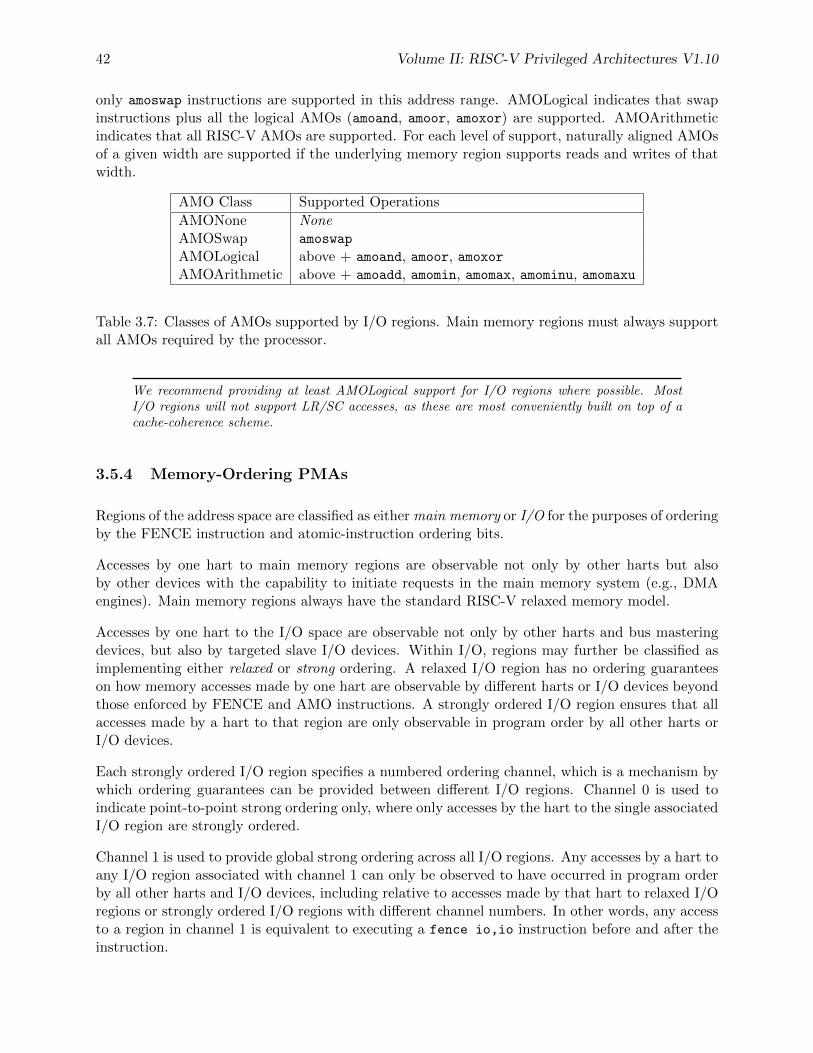
42 Volume II: RISC-V Privileged Architectures V1.10
only amoswap instructions are supported in this address range. AMOLogical indicates that swapinstructions plus all the logical AMOs (amoand, amoor, amoxor) are supported. AMOArithmeticindicates that all RISC-V AMOs are supported. For each level of support, naturally aligned AMOsof a given width are supported if the underlying memory region supports reads and writes of thatwidth.
AMO Class Supported Operations
AMONone NoneAMOSwap amoswap
AMOLogical above + amoand, amoor, amoxorAMOArithmetic above + amoadd, amomin, amomax, amominu, amomaxu
Table 3.7: Classes of AMOs supported by I/O regions. Main memory regions must always supportall AMOs required by the processor.
We recommend providing at least AMOLogical support for I/O regions where possible. MostI/O regions will not support LR/SC accesses, as these are most conveniently built on top of acache-coherence scheme.
3.5.4 Memory-Ordering PMAs
Regions of the address space are classified as either main memory or I/O for the purposes of orderingby the FENCE instruction and atomic-instruction ordering bits.
Accesses by one hart to main memory regions are observable not only by other harts but alsoby other devices with the capability to initiate requests in the main memory system (e.g., DMAengines). Main memory regions always have the standard RISC-V relaxed memory model.
Accesses by one hart to the I/O space are observable not only by other harts and bus masteringdevices, but also by targeted slave I/O devices. Within I/O, regions may further be classified asimplementing either relaxed or strong ordering. A relaxed I/O region has no ordering guaranteeson how memory accesses made by one hart are observable by different harts or I/O devices beyondthose enforced by FENCE and AMO instructions. A strongly ordered I/O region ensures that allaccesses made by a hart to that region are only observable in program order by all other harts orI/O devices.
Each strongly ordered I/O region specifies a numbered ordering channel, which is a mechanism bywhich ordering guarantees can be provided between different I/O regions. Channel 0 is used toindicate point-to-point strong ordering only, where only accesses by the hart to the single associatedI/O region are strongly ordered.
Channel 1 is used to provide global strong ordering across all I/O regions. Any accesses by a hart toany I/O region associated with channel 1 can only be observed to have occurred in program orderby all other harts and I/O devices, including relative to accesses made by that hart to relaxed I/Oregions or strongly ordered I/O regions with different channel numbers. In other words, any accessto a region in channel 1 is equivalent to executing a fence io,io instruction before and after theinstruction.
Volume II: RISC-V Privileged Architectures V1.10 43
Other larger channel numbers provide program ordering to accesses by that hart across any regionswith the same channel number.
Systems might support dynamic configuration of ordering properties on each memory region.
Strong ordering can be used to improve compatibility with legacy device driver code, or to enableincreased performance compared to insertion of explicit ordering instructions when the imple-mentation is known to not reorder accesses.
Local strong ordering (channel 0) is the default form of strong ordering as it is often straight-forward to provide if there is only a single in-order communication path between the hart andthe I/O device.
Generally, different strongly ordered I/O regions can share the same ordering channel withoutadditional ordering hardware if they share the same interconnect path and the path does notreorder requests.
3.5.5 Coherence and Cacheability PMAs
Coherence is a property defined for a single physical address, and indicates that writes to thataddress by one agent will eventually be made visible to other agents in the system. Coherenceis not to be confused with the memory consistency model of a system, which defines what valuesa memory read can return given the previous history of reads and writes to the entire memorysystem. In RISC-V platforms, the use of hardware-incoherent regions is discouraged due to softwarecomplexity, performance, and energy impacts.
The cacheability of a memory region should not affect the software view of the region exceptfor differences reflected in other PMAs, such as main memory versus I/O classification, memoryordering, supported accesses and atomic operations, and coherence. For this reason, we treatcacheability as a platform-level setting managed by machine-mode software only.
Where a platform supports configurable cacheability settings for a memory region, a platform-specific machine-mode routine will change the settings and flush caches if necessary, so the systemis only incoherent during the transition between cacheability settings. This transitory state shouldnot be visible to lower privilege levels.
We categorize RISC-V caches into three types: master-private, shared, and slave-private.Master-private caches are attached to a single master agent, i.e., one that issues read/writerequests to the memory system. Shared caches are located inbetween masters and slaves andmay be hierarchically organized. Slave-private caches do not impact coherence, as they are localto a single slave and do not affect other PMAs at a master, so are not considered further here.We use private cache to mean a master-private cache in the following section, unless explicitlystated otherwise.
Coherence is straightforward to provide for a shared memory region that is not cached by anyagent. The PMA for such a region would simply indicate it should not be cached in a private orshared cache.
Coherence is also straightforward for read-only regions, which can be safely cached by multipleagents without requiring a cache-coherence scheme. The PMA for this region would indicate thatit can be cached, but that writes are not supported.
Some read-write regions might only be accessed by a single agent, in which case they can becached privately by that agent without requiring a coherence scheme. The PMA for such regions
44 Volume II: RISC-V Privileged Architectures V1.10
would indicate they can be cached. The data can also be cached in a shared cache, as otheragents should not access the region.
If an agent can cache a read-write region that is accessible by other agents, whether cachingor non-caching, a cache-coherence scheme is required to avoid use of stale values. In regionslacking hardware cache coherence (hardware-incoherent regions), cache coherence can be im-plemented entirely in software, but software coherence schemes are notoriously difficult to im-plement correctly and often have severe performance impacts due to the need for conservativesoftware-directed cache-flushing. Hardware cache-coherence schemes require more complex hard-ware and can impact performance due to the cache-coherence probes, but are otherwise invisibleto software.
For each hardware cache-coherent region, the PMA would indicate that the region is coherentand which hardware coherence controller to use if the system has multiple coherence controllers.For some systems, the coherence controller might be an outer-level shared cache, which mightitself access further outer-level cache-coherence controllers hierarchically.
Most memory regions within a platform will be coherent to software, because they will befixed as either uncached, read-only, hardware cache-coherent, or only accessed by one agent.
3.5.6 Idempotency PMAs
Idempotency PMAs describe whether reads and writes to an address region are idempotent. Mainmemory regions are assumed to be idempotent. For I/O regions, idempotency on reads and writescan be specified separately (e.g., reads are idempotent but writes are not). If accesses are non-idempotent, i.e., there is potentially a side effect on any read or write access, then speculative orredundant accesses must be avoided.
For the purposes of defining the idempotency PMAs, changes in observed memory ordering createdby redundant accesses are not considered a side effect.
While hardware should always be designed to avoid speculative or redundant accesses to memoryregions marked as non-idempotent, it is also necessary to ensure software or compiler optimiza-tions do not generate spurious accesses to non-idempotent memory regions.
Non-idempotent regions might not support misaligned accesses, in which case software mightemulate misaligned accesses as a sequence of aligned accesses, each possibly causing side effects.Therefore, portable software should not issue misaligned accesses to non-idempotent regions.
3.6 Physical Memory Protection
To support secure processing and contain faults, it is desirable to limit the physical addressesaccessible by software running on a hart. An optional physical memory protection (PMP) unitprovides per-hart machine-mode control registers to allow physical memory access privileges (read,write, execute) to be specified for each physical memory region. The PMP values are checked inparallel with the PMA checks described in Section 3.5.
The granularity of PMP access control settings are platform-specific and within a platform mayvary by physical memory region, but the standard PMP encoding supports regions as small as fourbytes. Certain regions’ privileges can be hardwired—for example, some regions might only ever bevisible in machine mode but in no lower-privilege layers.
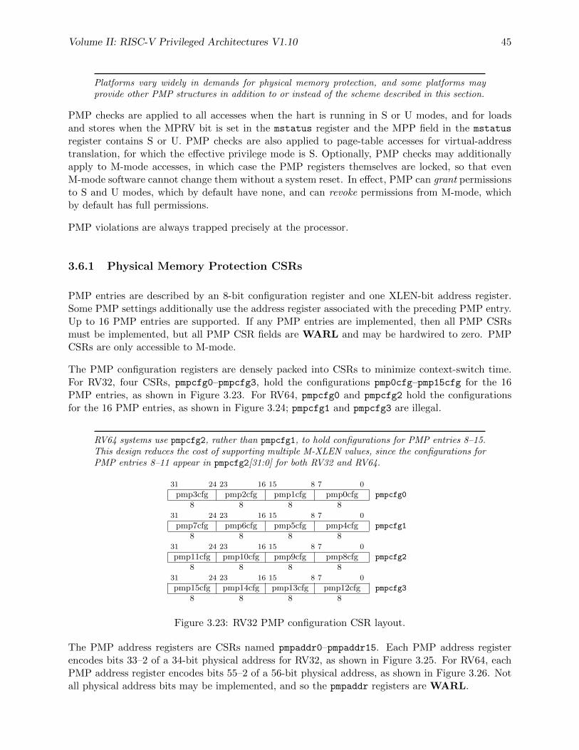
Volume II: RISC-V Privileged Architectures V1.10 45
Platforms vary widely in demands for physical memory protection, and some platforms mayprovide other PMP structures in addition to or instead of the scheme described in this section.
PMP checks are applied to all accesses when the hart is running in S or U modes, and for loadsand stores when the MPRV bit is set in the mstatus register and the MPP field in the mstatus
register contains S or U. PMP checks are also applied to page-table accesses for virtual-addresstranslation, for which the effective privilege mode is S. Optionally, PMP checks may additionallyapply to M-mode accesses, in which case the PMP registers themselves are locked, so that evenM-mode software cannot change them without a system reset. In effect, PMP can grant permissionsto S and U modes, which by default have none, and can revoke permissions from M-mode, whichby default has full permissions.
PMP violations are always trapped precisely at the processor.
3.6.1 Physical Memory Protection CSRs
PMP entries are described by an 8-bit configuration register and one XLEN-bit address register.Some PMP settings additionally use the address register associated with the preceding PMP entry.Up to 16 PMP entries are supported. If any PMP entries are implemented, then all PMP CSRsmust be implemented, but all PMP CSR fields are WARL and may be hardwired to zero. PMPCSRs are only accessible to M-mode.
The PMP configuration registers are densely packed into CSRs to minimize context-switch time.For RV32, four CSRs, pmpcfg0–pmpcfg3, hold the configurations pmp0cfg–pmp15cfg for the 16PMP entries, as shown in Figure 3.23. For RV64, pmpcfg0 and pmpcfg2 hold the configurationsfor the 16 PMP entries, as shown in Figure 3.24; pmpcfg1 and pmpcfg3 are illegal.
RV64 systems use pmpcfg2, rather than pmpcfg1, to hold configurations for PMP entries 8–15.This design reduces the cost of supporting multiple M-XLEN values, since the configurations forPMP entries 8–11 appear in pmpcfg2[31:0] for both RV32 and RV64.
31 24 23 16 15 8 7 0
pmp3cfg pmp2cfg pmp1cfg pmp0cfg pmpcfg0
8 8 8 831 24 23 16 15 8 7 0
pmp7cfg pmp6cfg pmp5cfg pmp4cfg pmpcfg1
8 8 8 831 24 23 16 15 8 7 0
pmp11cfg pmp10cfg pmp9cfg pmp8cfg pmpcfg2
8 8 8 831 24 23 16 15 8 7 0
pmp15cfg pmp14cfg pmp13cfg pmp12cfg pmpcfg3
8 8 8 8
Figure 3.23: RV32 PMP configuration CSR layout.
The PMP address registers are CSRs named pmpaddr0–pmpaddr15. Each PMP address registerencodes bits 33–2 of a 34-bit physical address for RV32, as shown in Figure 3.25. For RV64, eachPMP address register encodes bits 55–2 of a 56-bit physical address, as shown in Figure 3.26. Notall physical address bits may be implemented, and so the pmpaddr registers are WARL.
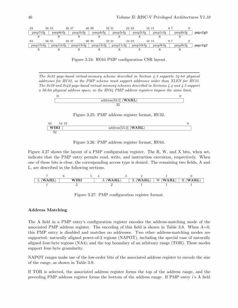
46 Volume II: RISC-V Privileged Architectures V1.10
63 56 55 48 47 40 39 32 31 24 23 16 15 8 7 0
pmp7cfg pmp6cfg pmp5cfg pmp4cfg pmp3cfg pmp2cfg pmp1cfg pmp0cfg pmpcfg0
8 8 8 8 8 8 8 863 56 55 48 47 40 39 32 31 24 23 16 15 8 7 0
pmp15cfg pmp14cfg pmp13cfg pmp12cfg pmp11cfg pmp10cfg pmp9cfg pmp8cfg pmpcfg2
8 8 8 8 8 8 8 8
Figure 3.24: RV64 PMP configuration CSR layout.
The Sv32 page-based virtual-memory scheme described in Section 4.3 supports 34-bit physicaladdresses for RV32, so the PMP scheme must support addresses wider than XLEN for RV32.The Sv39 and Sv48 page-based virtual-memory schemes described in Sections 4.4 and 4.5 supporta 56-bit physical address space, so the RV64 PMP address registers impose the same limit.
31 0
address[33:2] (WARL)
32
Figure 3.25: PMP address register format, RV32.
63 54 53 0
WIRI address[55:2] (WARL)
32
Figure 3.26: PMP address register format, RV64.
Figure 3.27 shows the layout of a PMP configuration register. The R, W, and X bits, when set,indicate that the PMP entry permits read, write, and instruction execution, respectively. Whenone of these bits is clear, the corresponding access type is denied. The remaining two fields, A andL, are described in the following sections.
7 6 5 4 3 2 1 0
L (WARL) WIRI A (WARL) X (WARL) W (WARL) R (WARL)
1 2 2 1 1 1
Figure 3.27: PMP configuration register format.
Address Matching
The A field in a PMP entry’s configuration register encodes the address-matching mode of theassociated PMP address register. The encoding of this field is shown in Table 3.8. When A=0,this PMP entry is disabled and matches no addresses. Two other address-matching modes aresupported: naturally aligned power-of-2 regions (NAPOT), including the special case of naturallyaligned four-byte regions (NA4); and the top boundary of an arbitrary range (TOR). These modessupport four-byte granularity.
NAPOT ranges make use of the low-order bits of the associated address register to encode the sizeof the range, as shown in Table 3.9.
If TOR is selected, the associated address register forms the top of the address range, and thepreceding PMP address register forms the bottom of the address range. If PMP entry i’s A field
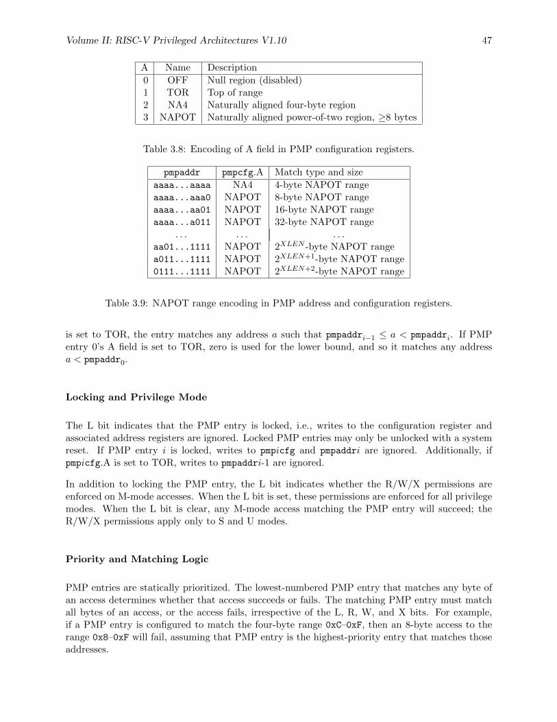
Volume II: RISC-V Privileged Architectures V1.10 47
A Name Description
0 OFF Null region (disabled)1 TOR Top of range2 NA4 Naturally aligned four-byte region3 NAPOT Naturally aligned power-of-two region, ≥8 bytes
Table 3.8: Encoding of A field in PMP configuration registers.
pmpaddr pmpcfg.A Match type and size
aaaa...aaaa NA4 4-byte NAPOT rangeaaaa...aaa0 NAPOT 8-byte NAPOT rangeaaaa...aa01 NAPOT 16-byte NAPOT rangeaaaa...a011 NAPOT 32-byte NAPOT range
. . . . . . . . .aa01...1111 NAPOT 2XLEN -byte NAPOT rangea011...1111 NAPOT 2XLEN+1-byte NAPOT range0111...1111 NAPOT 2XLEN+2-byte NAPOT range
Table 3.9: NAPOT range encoding in PMP address and configuration registers.
is set to TOR, the entry matches any address a such that pmpaddri−1 ≤ a < pmpaddri. If PMPentry 0’s A field is set to TOR, zero is used for the lower bound, and so it matches any addressa < pmpaddr0.
Locking and Privilege Mode
The L bit indicates that the PMP entry is locked, i.e., writes to the configuration register andassociated address registers are ignored. Locked PMP entries may only be unlocked with a systemreset. If PMP entry i is locked, writes to pmpicfg and pmpaddri are ignored. Additionally, ifpmpicfg.A is set to TOR, writes to pmpaddri-1 are ignored.
In addition to locking the PMP entry, the L bit indicates whether the R/W/X permissions areenforced on M-mode accesses. When the L bit is set, these permissions are enforced for all privilegemodes. When the L bit is clear, any M-mode access matching the PMP entry will succeed; theR/W/X permissions apply only to S and U modes.
Priority and Matching Logic
PMP entries are statically prioritized. The lowest-numbered PMP entry that matches any byte ofan access determines whether that access succeeds or fails. The matching PMP entry must matchall bytes of an access, or the access fails, irrespective of the L, R, W, and X bits. For example,if a PMP entry is configured to match the four-byte range 0xC–0xF, then an 8-byte access to therange 0x8–0xF will fail, assuming that PMP entry is the highest-priority entry that matches thoseaddresses.
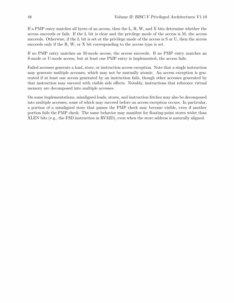
48 Volume II: RISC-V Privileged Architectures V1.10
If a PMP entry matches all bytes of an access, then the L, R, W, and X bits determine whether theaccess succeeds or fails. If the L bit is clear and the privilege mode of the access is M, the accesssucceeds. Otherwise, if the L bit is set or the privilege mode of the access is S or U, then the accesssucceeds only if the R, W, or X bit corresponding to the access type is set.
If no PMP entry matches an M-mode access, the access succeeds. If no PMP entry matches anS-mode or U-mode access, but at least one PMP entry is implemented, the access fails.
Failed accesses generate a load, store, or instruction access exception. Note that a single instructionmay generate multiple accesses, which may not be mutually atomic. An access exception is gen-erated if at least one access generated by an instruction fails, though other accesses generated bythat instruction may succeed with visible side effects. Notably, instructions that reference virtualmemory are decomposed into multiple accesses.
On some implementations, misaligned loads, stores, and instruction fetches may also be decomposedinto multiple accesses, some of which may succeed before an access exception occurs. In particular,a portion of a misaligned store that passes the PMP check may become visible, even if anotherportion fails the PMP check. The same behavior may manifest for floating-point stores wider thanXLEN bits (e.g., the FSD instruction in RV32D), even when the store address is naturally aligned.
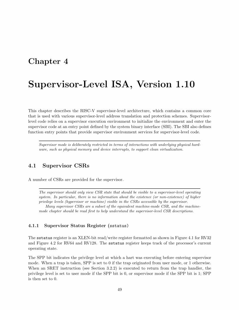
Chapter 4
Supervisor-Level ISA, Version 1.10
This chapter describes the RISC-V supervisor-level architecture, which contains a common corethat is used with various supervisor-level address translation and protection schemes. Supervisor-level code relies on a supervisor execution environment to initialize the environment and enter thesupervisor code at an entry point defined by the system binary interface (SBI). The SBI also definesfunction entry points that provide supervisor environment services for supervisor-level code.
Supervisor mode is deliberately restricted in terms of interactions with underlying physical hard-ware, such as physical memory and device interrupts, to support clean virtualization.
4.1 Supervisor CSRs
A number of CSRs are provided for the supervisor.
The supervisor should only view CSR state that should be visible to a supervisor-level operatingsystem. In particular, there is no information about the existence (or non-existence) of higherprivilege levels (hypervisor or machine) visible in the CSRs accessible by the supervisor.
Many supervisor CSRs are a subset of the equivalent machine-mode CSR, and the machine-mode chapter should be read first to help understand the supervisor-level CSR descriptions.
4.1.1 Supervisor Status Register (sstatus)
The sstatus register is an XLEN-bit read/write register formatted as shown in Figure 4.1 for RV32and Figure 4.2 for RV64 and RV128. The sstatus register keeps track of the processor’s currentoperating state.
The SPP bit indicates the privilege level at which a hart was executing before entering supervisormode. When a trap is taken, SPP is set to 0 if the trap originated from user mode, or 1 otherwise.When an SRET instruction (see Section 3.2.2) is executed to return from the trap handler, theprivilege level is set to user mode if the SPP bit is 0, or supervisor mode if the SPP bit is 1; SPPis then set to 0.
49
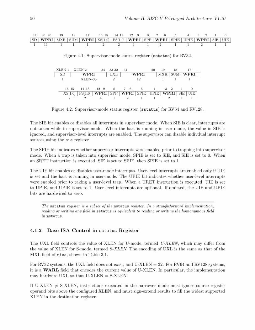
50 Volume II: RISC-V Privileged Architectures V1.10
31 30 20 19 18 17 16 15 14 13 12 9 8 7 6 5 4 3 2 1 0
SD WPRI MXR SUM WPRI XS[1:0] FS[1:0] WPRI SPP WPRI SPIE UPIE WPRI SIE UIE
1 11 1 1 1 2 2 4 1 2 1 1 2 1 1
Figure 4.1: Supervisor-mode status register (sstatus) for RV32.
XLEN-1 XLEN-2 34 33 32 31 20 19 18 17
SD WPRI UXL WPRI MXR SUM WPRI
1 XLEN-35 2 12 1 1 1
16 15 14 13 12 9 8 7 6 5 4 3 2 1 0
XS[1:0] FS[1:0] WPRI SPP WPRI SPIE UPIE WPRI SIE UIE
2 2 4 1 2 1 1 2 1 1
Figure 4.2: Supervisor-mode status register (sstatus) for RV64 and RV128.
The SIE bit enables or disables all interrupts in supervisor mode. When SIE is clear, interrupts arenot taken while in supervisor mode. When the hart is running in user-mode, the value in SIE isignored, and supervisor-level interrupts are enabled. The supervisor can disable indivdual interruptsources using the sie register.
The SPIE bit indicates whether supervisor interrupts were enabled prior to trapping into supervisormode. When a trap is taken into supervisor mode, SPIE is set to SIE, and SIE is set to 0. Whenan SRET instruction is executed, SIE is set to SPIE, then SPIE is set to 1.
The UIE bit enables or disables user-mode interrupts. User-level interrupts are enabled only if UIEis set and the hart is running in user-mode. The UPIE bit indicates whether user-level interruptswere enabled prior to taking a user-level trap. When a URET instruction is executed, UIE is setto UPIE, and UPIE is set to 1. User-level interrupts are optional. If omitted, the UIE and UPIEbits are hardwired to zero.
The sstatus register is a subset of the mstatus register. In a straightforward implementation,reading or writing any field in sstatus is equivalent to reading or writing the homonymous fieldin mstatus.
4.1.2 Base ISA Control in sstatus Register
The UXL field controls the value of XLEN for U-mode, termed U-XLEN, which may differ fromthe value of XLEN for S-mode, termed S-XLEN. The encoding of UXL is the same as that of theMXL field of misa, shown in Table 3.1.
For RV32 systems, the UXL field does not exist, and U-XLEN = 32. For RV64 and RV128 systems,it is a WARL field that encodes the current value of U-XLEN. In particular, the implementationmay hardwire UXL so that U-XLEN = S-XLEN.
If U-XLEN 6= S-XLEN, instructions executed in the narrower mode must ignore source registeroperand bits above the configured XLEN, and must sign-extend results to fill the widest supportedXLEN in the destination register.
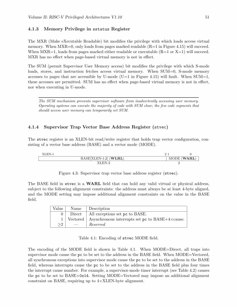
Volume II: RISC-V Privileged Architectures V1.10 51
4.1.3 Memory Privilege in sstatus Register
The MXR (Make eXecutable Readable) bit modifies the privilege with which loads access virtualmemory. When MXR=0, only loads from pages marked readable (R=1 in Figure 4.15) will succeed.When MXR=1, loads from pages marked either readable or executable (R=1 or X=1) will succeed.MXR has no effect when page-based virtual memory is not in effect.
The SUM (permit Supervisor User Memory access) bit modifies the privilege with which S-modeloads, stores, and instruction fetches access virtual memory. When SUM=0, S-mode memoryaccesses to pages that are accessible by U-mode (U=1 in Figure 4.15) will fault. When SUM=1,these accesses are permitted. SUM has no effect when page-based virtual memory is not in effect,nor when executing in U-mode.
The SUM mechanism prevents supervisor software from inadvertently accessing user memory.Operating systems can execute the majority of code with SUM clear; the few code segments thatshould access user memory can temporarily set SUM.
4.1.4 Supervisor Trap Vector Base Address Register (stvec)
The stvec register is an XLEN-bit read/write register that holds trap vector configuration, con-sisting of a vector base address (BASE) and a vector mode (MODE).
XLEN-1 2 1 0
BASE[XLEN-1:2] (WLRL) MODE (WARL)
XLEN-2 2
Figure 4.3: Supervisor trap vector base address register (stvec).
The BASE field in stvec is a WARL field that can hold any valid virtual or physical address,subject to the following alignment constraints: the address must always be at least 4-byte aligned,and the MODE setting may impose additional alignment constraints on the value in the BASEfield.
Value Name Description
0 Direct All exceptions set pc to BASE.1 Vectored Asynchronous interrupts set pc to BASE+4×cause.≥2 — Reserved
Table 4.1: Encoding of stvec MODE field.
The encoding of the MODE field is shown in Table 4.1. When MODE=Direct, all traps intosupervisor mode cause the pc to be set to the address in the BASE field. When MODE=Vectored,all synchronous exceptions into supervisor mode cause the pc to be set to the address in the BASEfield, whereas interrupts cause the pc to be set to the address in the BASE field plus four timesthe interrupt cause number. For example, a supervisor-mode timer interrupt (see Table 4.2) causesthe pc to be set to BASE+0x14. Setting MODE=Vectored may impose an additional alignmentconstraint on BASE, requiring up to 4×XLEN-byte alignment.
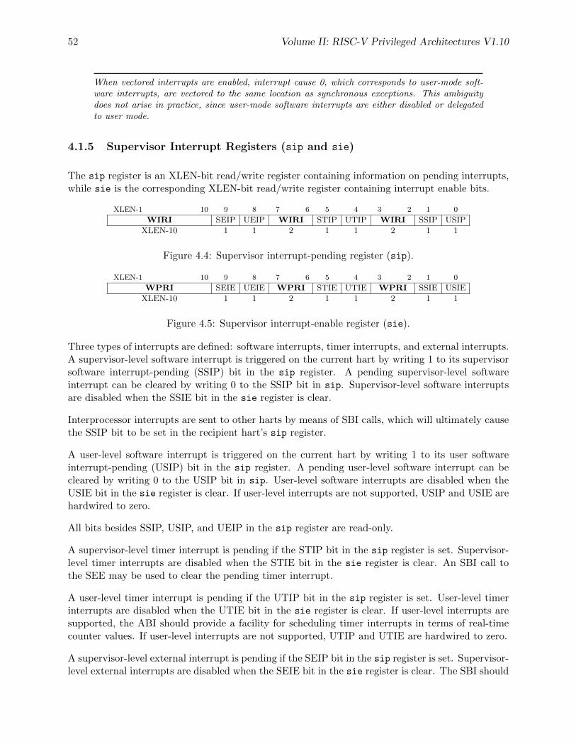
52 Volume II: RISC-V Privileged Architectures V1.10
When vectored interrupts are enabled, interrupt cause 0, which corresponds to user-mode soft-ware interrupts, are vectored to the same location as synchronous exceptions. This ambiguitydoes not arise in practice, since user-mode software interrupts are either disabled or delegatedto user mode.
4.1.5 Supervisor Interrupt Registers (sip and sie)
The sip register is an XLEN-bit read/write register containing information on pending interrupts,while sie is the corresponding XLEN-bit read/write register containing interrupt enable bits.
XLEN-1 10 9 8 7 6 5 4 3 2 1 0
WIRI SEIP UEIP WIRI STIP UTIP WIRI SSIP USIP
XLEN-10 1 1 2 1 1 2 1 1
Figure 4.4: Supervisor interrupt-pending register (sip).
XLEN-1 10 9 8 7 6 5 4 3 2 1 0
WPRI SEIE UEIE WPRI STIE UTIE WPRI SSIE USIE
XLEN-10 1 1 2 1 1 2 1 1
Figure 4.5: Supervisor interrupt-enable register (sie).
Three types of interrupts are defined: software interrupts, timer interrupts, and external interrupts.A supervisor-level software interrupt is triggered on the current hart by writing 1 to its supervisorsoftware interrupt-pending (SSIP) bit in the sip register. A pending supervisor-level softwareinterrupt can be cleared by writing 0 to the SSIP bit in sip. Supervisor-level software interruptsare disabled when the SSIE bit in the sie register is clear.
Interprocessor interrupts are sent to other harts by means of SBI calls, which will ultimately causethe SSIP bit to be set in the recipient hart’s sip register.
A user-level software interrupt is triggered on the current hart by writing 1 to its user softwareinterrupt-pending (USIP) bit in the sip register. A pending user-level software interrupt can becleared by writing 0 to the USIP bit in sip. User-level software interrupts are disabled when theUSIE bit in the sie register is clear. If user-level interrupts are not supported, USIP and USIE arehardwired to zero.
All bits besides SSIP, USIP, and UEIP in the sip register are read-only.
A supervisor-level timer interrupt is pending if the STIP bit in the sip register is set. Supervisor-level timer interrupts are disabled when the STIE bit in the sie register is clear. An SBI call tothe SEE may be used to clear the pending timer interrupt.
A user-level timer interrupt is pending if the UTIP bit in the sip register is set. User-level timerinterrupts are disabled when the UTIE bit in the sie register is clear. If user-level interrupts aresupported, the ABI should provide a facility for scheduling timer interrupts in terms of real-timecounter values. If user-level interrupts are not supported, UTIP and UTIE are hardwired to zero.
A supervisor-level external interrupt is pending if the SEIP bit in the sip register is set. Supervisor-level external interrupts are disabled when the SEIE bit in the sie register is clear. The SBI should
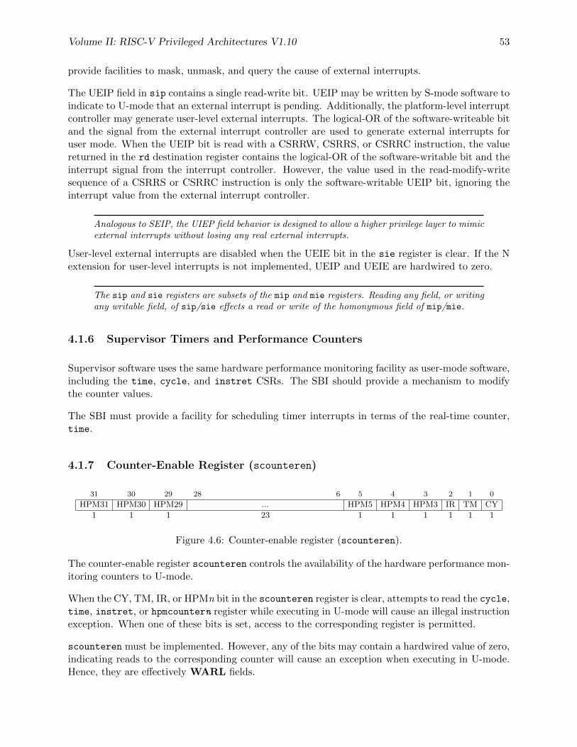
Volume II: RISC-V Privileged Architectures V1.10 53
provide facilities to mask, unmask, and query the cause of external interrupts.
The UEIP field in sip contains a single read-write bit. UEIP may be written by S-mode software toindicate to U-mode that an external interrupt is pending. Additionally, the platform-level interruptcontroller may generate user-level external interrupts. The logical-OR of the software-writeable bitand the signal from the external interrupt controller are used to generate external interrupts foruser mode. When the UEIP bit is read with a CSRRW, CSRRS, or CSRRC instruction, the valuereturned in the rd destination register contains the logical-OR of the software-writable bit and theinterrupt signal from the interrupt controller. However, the value used in the read-modify-writesequence of a CSRRS or CSRRC instruction is only the software-writable UEIP bit, ignoring theinterrupt value from the external interrupt controller.
Analogous to SEIP, the UIEP field behavior is designed to allow a higher privilege layer to mimicexternal interrupts without losing any real external interrupts.
User-level external interrupts are disabled when the UEIE bit in the sie register is clear. If the Nextension for user-level interrupts is not implemented, UEIP and UEIE are hardwired to zero.
The sip and sie registers are subsets of the mip and mie registers. Reading any field, or writingany writable field, of sip/sie effects a read or write of the homonymous field of mip/mie.
4.1.6 Supervisor Timers and Performance Counters
Supervisor software uses the same hardware performance monitoring facility as user-mode software,including the time, cycle, and instret CSRs. The SBI should provide a mechanism to modifythe counter values.
The SBI must provide a facility for scheduling timer interrupts in terms of the real-time counter,time.
4.1.7 Counter-Enable Register (scounteren)
31 30 29 28 6 5 4 3 2 1 0
HPM31 HPM30 HPM29 ... HPM5 HPM4 HPM3 IR TM CY
1 1 1 23 1 1 1 1 1 1
Figure 4.6: Counter-enable register (scounteren).
The counter-enable register scounteren controls the availability of the hardware performance mon-itoring counters to U-mode.
When the CY, TM, IR, or HPMn bit in the scounteren register is clear, attempts to read the cycle,time, instret, or hpmcountern register while executing in U-mode will cause an illegal instructionexception. When one of these bits is set, access to the corresponding register is permitted.
scounteren must be implemented. However, any of the bits may contain a hardwired value of zero,indicating reads to the corresponding counter will cause an exception when executing in U-mode.Hence, they are effectively WARL fields.
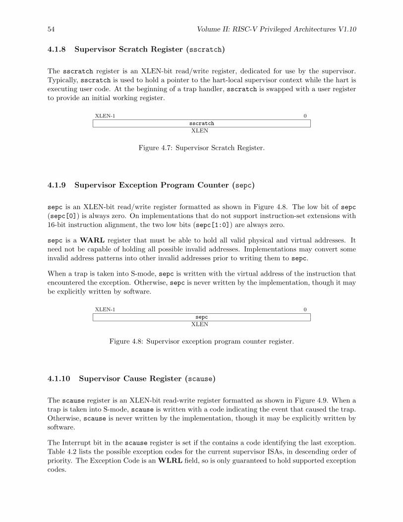
54 Volume II: RISC-V Privileged Architectures V1.10
4.1.8 Supervisor Scratch Register (sscratch)
The sscratch register is an XLEN-bit read/write register, dedicated for use by the supervisor.Typically, sscratch is used to hold a pointer to the hart-local supervisor context while the hart isexecuting user code. At the beginning of a trap handler, sscratch is swapped with a user registerto provide an initial working register.
XLEN-1 0
sscratch
XLEN
Figure 4.7: Supervisor Scratch Register.
4.1.9 Supervisor Exception Program Counter (sepc)
sepc is an XLEN-bit read/write register formatted as shown in Figure 4.8. The low bit of sepc(sepc[0]) is always zero. On implementations that do not support instruction-set extensions with16-bit instruction alignment, the two low bits (sepc[1:0]) are always zero.
sepc is a WARL register that must be able to hold all valid physical and virtual addresses. Itneed not be capable of holding all possible invalid addresses. Implementations may convert someinvalid address patterns into other invalid addresses prior to writing them to sepc.
When a trap is taken into S-mode, sepc is written with the virtual address of the instruction thatencountered the exception. Otherwise, sepc is never written by the implementation, though it maybe explicitly written by software.
XLEN-1 0
sepc
XLEN
Figure 4.8: Supervisor exception program counter register.
4.1.10 Supervisor Cause Register (scause)
The scause register is an XLEN-bit read-write register formatted as shown in Figure 4.9. When atrap is taken into S-mode, scause is written with a code indicating the event that caused the trap.Otherwise, scause is never written by the implementation, though it may be explicitly written bysoftware.
The Interrupt bit in the scause register is set if the contains a code identifying the last exception.Table 4.2 lists the possible exception codes for the current supervisor ISAs, in descending order ofpriority. The Exception Code is an WLRL field, so is only guaranteed to hold supported exceptioncodes.
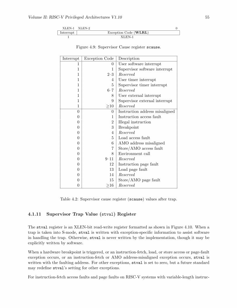
Volume II: RISC-V Privileged Architectures V1.10 55
XLEN-1 XLEN-2 0
Interrupt Exception Code (WLRL)
1 XLEN-1
Figure 4.9: Supervisor Cause register scause.
Interrupt Exception Code Description
1 0 User software interrupt1 1 Supervisor software interrupt1 2–3 Reserved1 4 User timer interrupt1 5 Supervisor timer interrupt1 6–7 Reserved1 8 User external interrupt1 9 Supervisor external interrupt1 ≥10 Reserved
0 0 Instruction address misaligned0 1 Instruction access fault0 2 Illegal instruction0 3 Breakpoint0 4 Reserved0 5 Load access fault0 6 AMO address misaligned0 7 Store/AMO access fault0 8 Environment call0 9–11 Reserved0 12 Instruction page fault0 13 Load page fault0 14 Reserved0 15 Store/AMO page fault0 ≥16 Reserved
Table 4.2: Supervisor cause register (scause) values after trap.
4.1.11 Supervisor Trap Value (stval) Register
The stval register is an XLEN-bit read-write register formatted as shown in Figure 4.10. When atrap is taken into S-mode, stval is written with exception-specific information to assist softwarein handling the trap. Otherwise, stval is never written by the implementation, though it may beexplicitly written by software.
When a hardware breakpoint is triggered, or an instruction-fetch, load, or store access or page-faultexception occurs, or an instruction-fetch or AMO address-misaligned exception occurs, stval iswritten with the faulting address. For other exceptions, stval is set to zero, but a future standardmay redefine stval’s setting for other exceptions.
For instruction-fetch access faults and page faults on RISC-V systems with variable-length instruc-
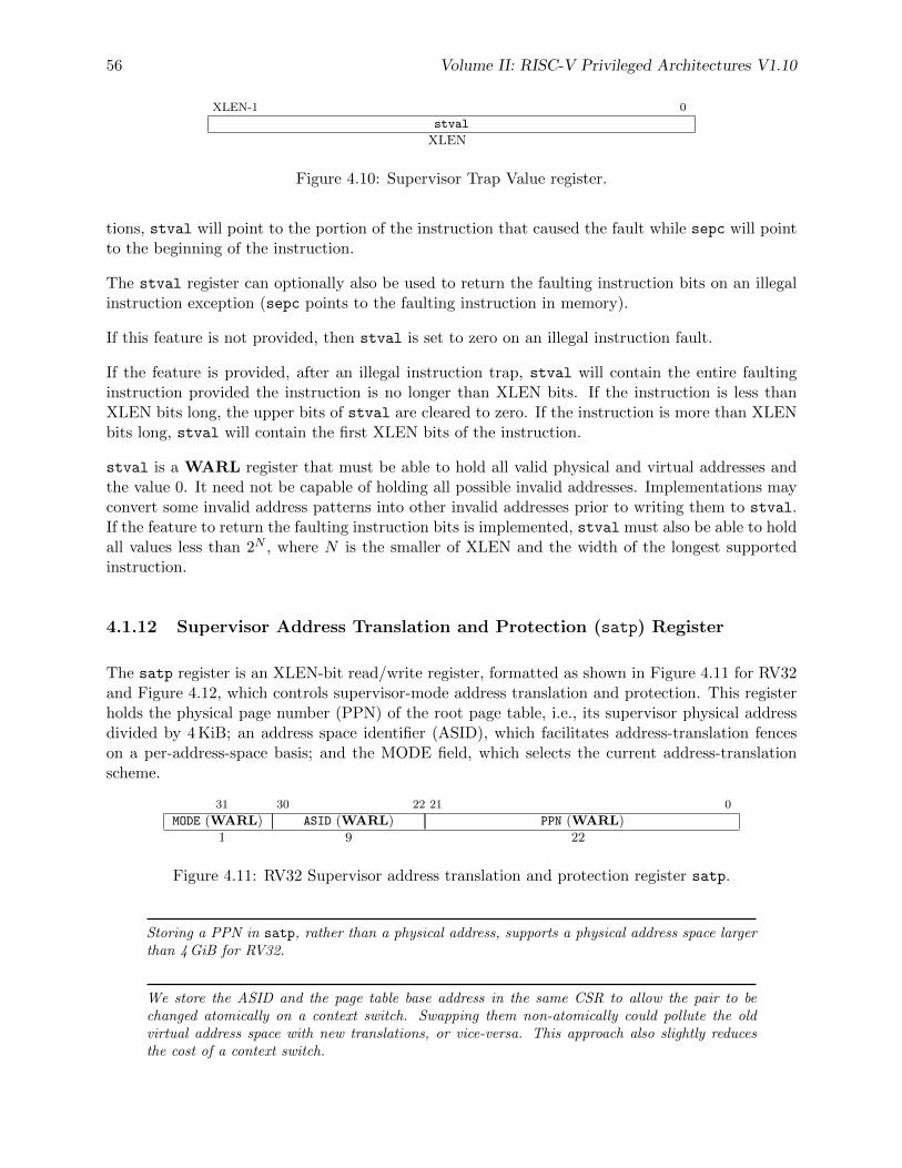
56 Volume II: RISC-V Privileged Architectures V1.10
XLEN-1 0
stval
XLEN
Figure 4.10: Supervisor Trap Value register.
tions, stval will point to the portion of the instruction that caused the fault while sepc will pointto the beginning of the instruction.
The stval register can optionally also be used to return the faulting instruction bits on an illegalinstruction exception (sepc points to the faulting instruction in memory).
If this feature is not provided, then stval is set to zero on an illegal instruction fault.
If the feature is provided, after an illegal instruction trap, stval will contain the entire faultinginstruction provided the instruction is no longer than XLEN bits. If the instruction is less thanXLEN bits long, the upper bits of stval are cleared to zero. If the instruction is more than XLENbits long, stval will contain the first XLEN bits of the instruction.
stval is a WARL register that must be able to hold all valid physical and virtual addresses andthe value 0. It need not be capable of holding all possible invalid addresses. Implementations mayconvert some invalid address patterns into other invalid addresses prior to writing them to stval.If the feature to return the faulting instruction bits is implemented, stval must also be able to holdall values less than 2N , where N is the smaller of XLEN and the width of the longest supportedinstruction.
4.1.12 Supervisor Address Translation and Protection (satp) Register
The satp register is an XLEN-bit read/write register, formatted as shown in Figure 4.11 for RV32and Figure 4.12, which controls supervisor-mode address translation and protection. This registerholds the physical page number (PPN) of the root page table, i.e., its supervisor physical addressdivided by 4 KiB; an address space identifier (ASID), which facilitates address-translation fenceson a per-address-space basis; and the MODE field, which selects the current address-translationscheme.
31 30 22 21 0
MODE (WARL) ASID (WARL) PPN (WARL)
1 9 22
Figure 4.11: RV32 Supervisor address translation and protection register satp.
Storing a PPN in satp, rather than a physical address, supports a physical address space largerthan 4 GiB for RV32.
We store the ASID and the page table base address in the same CSR to allow the pair to bechanged atomically on a context switch. Swapping them non-atomically could pollute the oldvirtual address space with new translations, or vice-versa. This approach also slightly reducesthe cost of a context switch.
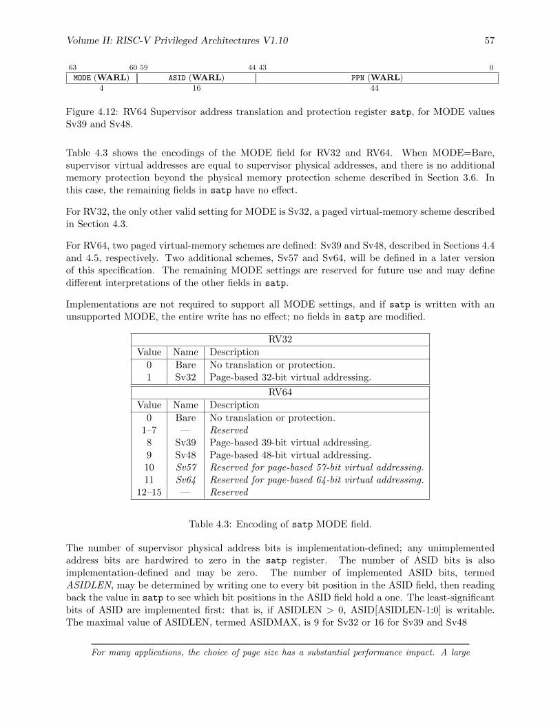
Volume II: RISC-V Privileged Architectures V1.10 57
63 60 59 44 43 0
MODE (WARL) ASID (WARL) PPN (WARL)
4 16 44
Figure 4.12: RV64 Supervisor address translation and protection register satp, for MODE valuesSv39 and Sv48.
Table 4.3 shows the encodings of the MODE field for RV32 and RV64. When MODE=Bare,supervisor virtual addresses are equal to supervisor physical addresses, and there is no additionalmemory protection beyond the physical memory protection scheme described in Section 3.6. Inthis case, the remaining fields in satp have no effect.
For RV32, the only other valid setting for MODE is Sv32, a paged virtual-memory scheme describedin Section 4.3.
For RV64, two paged virtual-memory schemes are defined: Sv39 and Sv48, described in Sections 4.4and 4.5, respectively. Two additional schemes, Sv57 and Sv64, will be defined in a later versionof this specification. The remaining MODE settings are reserved for future use and may definedifferent interpretations of the other fields in satp.
Implementations are not required to support all MODE settings, and if satp is written with anunsupported MODE, the entire write has no effect; no fields in satp are modified.
RV32
Value Name Description
0 Bare No translation or protection.1 Sv32 Page-based 32-bit virtual addressing.
RV64
Value Name Description
0 Bare No translation or protection.1–7 — Reserved8 Sv39 Page-based 39-bit virtual addressing.9 Sv48 Page-based 48-bit virtual addressing.10 Sv57 Reserved for page-based 57-bit virtual addressing.11 Sv64 Reserved for page-based 64-bit virtual addressing.
12–15 — Reserved
Table 4.3: Encoding of satp MODE field.
The number of supervisor physical address bits is implementation-defined; any unimplementedaddress bits are hardwired to zero in the satp register. The number of ASID bits is alsoimplementation-defined and may be zero. The number of implemented ASID bits, termedASIDLEN, may be determined by writing one to every bit position in the ASID field, then readingback the value in satp to see which bit positions in the ASID field hold a one. The least-significantbits of ASID are implemented first: that is, if ASIDLEN > 0, ASID[ASIDLEN-1:0] is writable.The maximal value of ASIDLEN, termed ASIDMAX, is 9 for Sv32 or 16 for Sv39 and Sv48
For many applications, the choice of page size has a substantial performance impact. A large
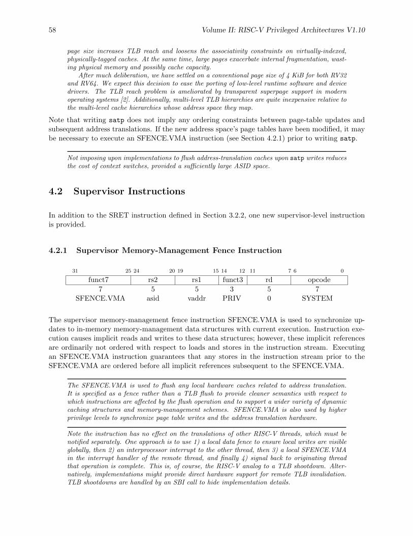
58 Volume II: RISC-V Privileged Architectures V1.10
page size increases TLB reach and loosens the associativity constraints on virtually-indexed,physically-tagged caches. At the same time, large pages exacerbate internal fragmentation, wast-ing physical memory and possibly cache capacity.
After much deliberation, we have settled on a conventional page size of 4 KiB for both RV32and RV64. We expect this decision to ease the porting of low-level runtime software and devicedrivers. The TLB reach problem is ameliorated by transparent superpage support in modernoperating systems [2]. Additionally, multi-level TLB hierarchies are quite inexpensive relative tothe multi-level cache hierarchies whose address space they map.
Note that writing satp does not imply any ordering constraints between page-table updates andsubsequent address translations. If the new address space’s page tables have been modified, it maybe necessary to execute an SFENCE.VMA instruction (see Section 4.2.1) prior to writing satp.
Not imposing upon implementations to flush address-translation caches upon satp writes reducesthe cost of context switches, provided a sufficiently large ASID space.
4.2 Supervisor Instructions
In addition to the SRET instruction defined in Section 3.2.2, one new supervisor-level instructionis provided.
4.2.1 Supervisor Memory-Management Fence Instruction
31 25 24 20 19 15 14 12 11 7 6 0
funct7 rs2 rs1 funct3 rd opcode
7 5 5 3 5 7SFENCE.VMA asid vaddr PRIV 0 SYSTEM
The supervisor memory-management fence instruction SFENCE.VMA is used to synchronize up-dates to in-memory memory-management data structures with current execution. Instruction exe-cution causes implicit reads and writes to these data structures; however, these implicit referencesare ordinarily not ordered with respect to loads and stores in the instruction stream. Executingan SFENCE.VMA instruction guarantees that any stores in the instruction stream prior to theSFENCE.VMA are ordered before all implicit references subsequent to the SFENCE.VMA.
The SFENCE.VMA is used to flush any local hardware caches related to address translation.It is specified as a fence rather than a TLB flush to provide cleaner semantics with respect towhich instructions are affected by the flush operation and to support a wider variety of dynamiccaching structures and memory-management schemes. SFENCE.VMA is also used by higherprivilege levels to synchronize page table writes and the address translation hardware.
Note the instruction has no effect on the translations of other RISC-V threads, which must benotified separately. One approach is to use 1) a local data fence to ensure local writes are visibleglobally, then 2) an interprocessor interrupt to the other thread, then 3) a local SFENCE.VMAin the interrupt handler of the remote thread, and finally 4) signal back to originating threadthat operation is complete. This is, of course, the RISC-V analog to a TLB shootdown. Alter-natively, implementations might provide direct hardware support for remote TLB invalidation.TLB shootdowns are handled by an SBI call to hide implementation details.
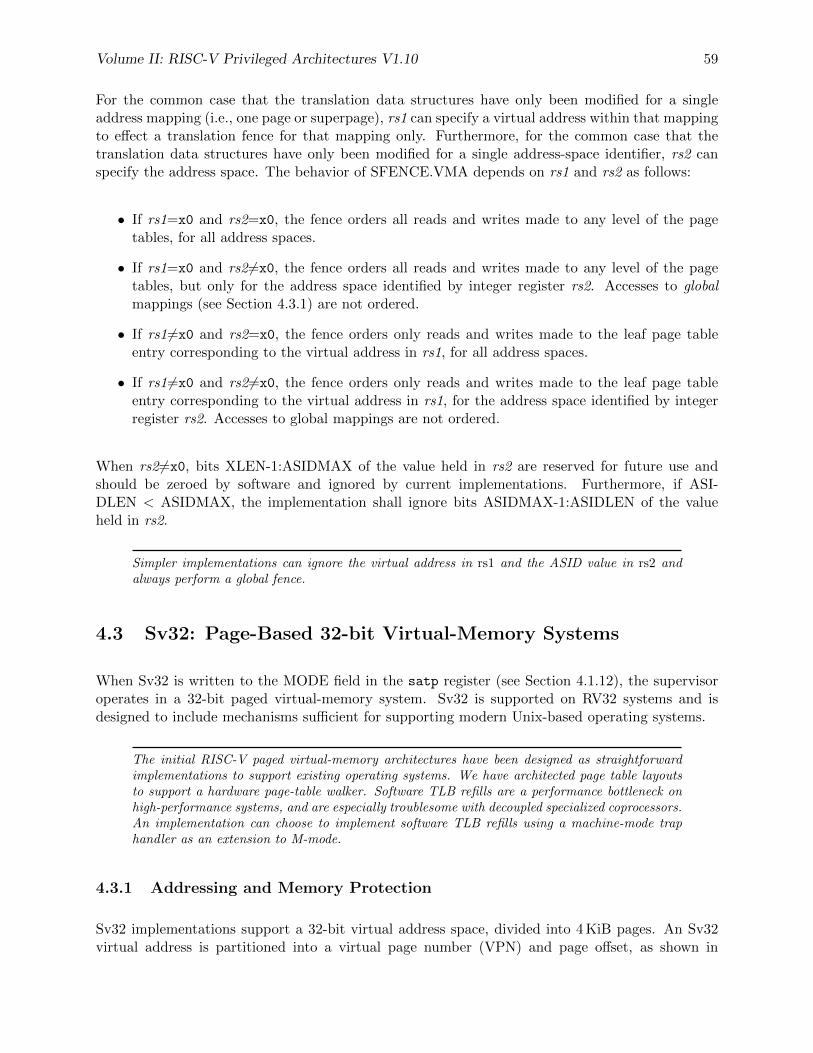
Volume II: RISC-V Privileged Architectures V1.10 59
For the common case that the translation data structures have only been modified for a singleaddress mapping (i.e., one page or superpage), rs1 can specify a virtual address within that mappingto effect a translation fence for that mapping only. Furthermore, for the common case that thetranslation data structures have only been modified for a single address-space identifier, rs2 canspecify the address space. The behavior of SFENCE.VMA depends on rs1 and rs2 as follows:
• If rs1=x0 and rs2=x0, the fence orders all reads and writes made to any level of the pagetables, for all address spaces.
• If rs1=x0 and rs26=x0, the fence orders all reads and writes made to any level of the pagetables, but only for the address space identified by integer register rs2. Accesses to globalmappings (see Section 4.3.1) are not ordered.
• If rs16=x0 and rs2=x0, the fence orders only reads and writes made to the leaf page tableentry corresponding to the virtual address in rs1, for all address spaces.
• If rs16=x0 and rs26=x0, the fence orders only reads and writes made to the leaf page tableentry corresponding to the virtual address in rs1, for the address space identified by integerregister rs2. Accesses to global mappings are not ordered.
When rs2 6=x0, bits XLEN-1:ASIDMAX of the value held in rs2 are reserved for future use andshould be zeroed by software and ignored by current implementations. Furthermore, if ASI-DLEN < ASIDMAX, the implementation shall ignore bits ASIDMAX-1:ASIDLEN of the valueheld in rs2.
Simpler implementations can ignore the virtual address in rs1 and the ASID value in rs2 andalways perform a global fence.
4.3 Sv32: Page-Based 32-bit Virtual-Memory Systems
When Sv32 is written to the MODE field in the satp register (see Section 4.1.12), the supervisoroperates in a 32-bit paged virtual-memory system. Sv32 is supported on RV32 systems and isdesigned to include mechanisms sufficient for supporting modern Unix-based operating systems.
The initial RISC-V paged virtual-memory architectures have been designed as straightforwardimplementations to support existing operating systems. We have architected page table layoutsto support a hardware page-table walker. Software TLB refills are a performance bottleneck onhigh-performance systems, and are especially troublesome with decoupled specialized coprocessors.An implementation can choose to implement software TLB refills using a machine-mode traphandler as an extension to M-mode.
4.3.1 Addressing and Memory Protection
Sv32 implementations support a 32-bit virtual address space, divided into 4 KiB pages. An Sv32virtual address is partitioned into a virtual page number (VPN) and page offset, as shown in
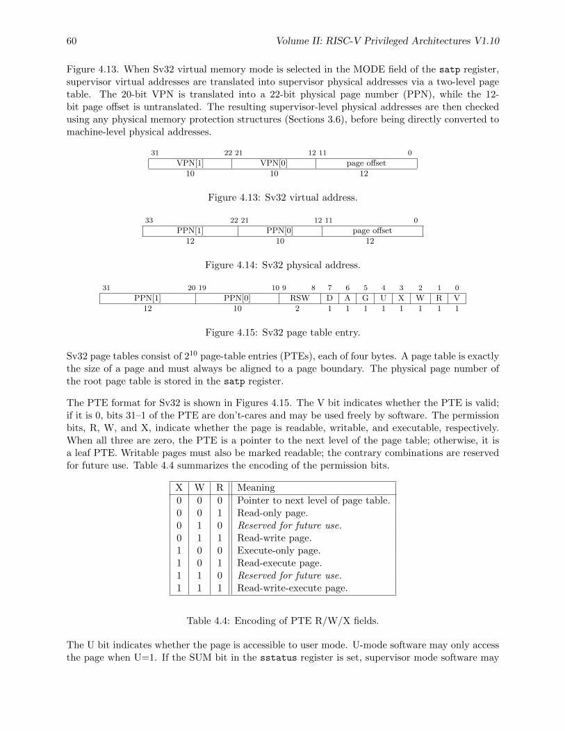
60 Volume II: RISC-V Privileged Architectures V1.10
Figure 4.13. When Sv32 virtual memory mode is selected in the MODE field of the satp register,supervisor virtual addresses are translated into supervisor physical addresses via a two-level pagetable. The 20-bit VPN is translated into a 22-bit physical page number (PPN), while the 12-bit page offset is untranslated. The resulting supervisor-level physical addresses are then checkedusing any physical memory protection structures (Sections 3.6), before being directly converted tomachine-level physical addresses.
31 22 21 12 11 0
VPN[1] VPN[0] page offset
10 10 12
Figure 4.13: Sv32 virtual address.
33 22 21 12 11 0
PPN[1] PPN[0] page offset
12 10 12
Figure 4.14: Sv32 physical address.
31 20 19 10 9 8 7 6 5 4 3 2 1 0
PPN[1] PPN[0] RSW D A G U X W R V
12 10 2 1 1 1 1 1 1 1 1
Figure 4.15: Sv32 page table entry.
Sv32 page tables consist of 210 page-table entries (PTEs), each of four bytes. A page table is exactlythe size of a page and must always be aligned to a page boundary. The physical page number ofthe root page table is stored in the satp register.
The PTE format for Sv32 is shown in Figures 4.15. The V bit indicates whether the PTE is valid;if it is 0, bits 31–1 of the PTE are don’t-cares and may be used freely by software. The permissionbits, R, W, and X, indicate whether the page is readable, writable, and executable, respectively.When all three are zero, the PTE is a pointer to the next level of the page table; otherwise, it isa leaf PTE. Writable pages must also be marked readable; the contrary combinations are reservedfor future use. Table 4.4 summarizes the encoding of the permission bits.
X W R Meaning
0 0 0 Pointer to next level of page table.0 0 1 Read-only page.0 1 0 Reserved for future use.0 1 1 Read-write page.1 0 0 Execute-only page.1 0 1 Read-execute page.1 1 0 Reserved for future use.1 1 1 Read-write-execute page.
Table 4.4: Encoding of PTE R/W/X fields.
The U bit indicates whether the page is accessible to user mode. U-mode software may only accessthe page when U=1. If the SUM bit in the sstatus register is set, supervisor mode software may
Volume II: RISC-V Privileged Architectures V1.10 61
also access pages with U=1. However, supervisor code normally operates with the SUM bit clear,in which case, supervisor code will fault on accesses to user-mode pages.
An alternative PTE format would support different permissions for supervisor and user. Weomitted this feature because it would be largely redundant with the SUM mechanism (see Sec-tion 4.1.3) and would require more encoding space in the PTE.
The G bit designates a global mapping. Global mappings are those that exist in all address spaces.For non-leaf PTEs, the global setting implies that all mappings in the subsequent levels of the pagetable are global. Note that failing to mark a global mapping as global merely reduces performance,whereas marking a non-global mapping as global is an error.
Global mappings need not be stored redundantly in address-translation caches for multipleASIDs. Additionally, they need not be flushed from local address-translation caches when anSFENCE.VMA instruction is executed with rs2 6=x0.
The RSW field is reserved for use by supervisor software; the implementation shall ignore this field.
Each leaf PTE contains an accessed (A) and dirty (D) bit. The A bit indicates the virtual page hasbeen read, written, or fetched from since the last time the A bit was cleared. The D bit indicatesthe virtual page has been written since the last time the D bit was cleared.
Two schemes to manage the A and D bits are permitted:
• When a virtual page is accessed and the A bit is clear, or is written and the D bit is clear,the implementation sets the corresponding bit in the PTE. The PTE update must be atomicwith respect to other accesses to the PTE, and must atomically check that the PTE is validand grants sufficient permissions. The PTE update must be exact (i.e., not speculative), andobserved in program order by the local hart. The ordering on loads and stores provided byFENCE instructions and the acquire/release bits on atomic instructions also orders the PTEupdates associated with those loads and stores as observed by remote harts.
• When a virtual page is accessed and the A bit is clear, or is written and the D bit is clear, apage-fault exception is raised.
Standard supervisor software should be written to assume either or both PTE update schemes maybe in effect.
Mandating that the PTE updates to be exact, atomic, and in program order simplifies the spec-ification, and makes the feature more useful for system software. Simple implementations mayinstead generate page-fault exceptions.
The A and D bits are never cleared by the implementation. If the supervisor software doesnot rely on accessed and/or dirty bits, e.g. if it does not swap memory pages to secondary storageor if the pages are being used to map I/O space, it should always set them to 1 in the PTE toimprove performance.
Any level of PTE may be a leaf PTE, so in addition to 4 KiB pages, Sv32 supports 4 MiB megapages.A megapage must be virtually and physically aligned to a 4 MiB boundary; a page-fault exceptionis raised if the physical address is insufficiently aligned.
For non-leaf PTEs, the D, A, and U bits are reserved for future use and must be cleared by softwarefor forward compatibility.
62 Volume II: RISC-V Privileged Architectures V1.10
4.3.2 Virtual Address Translation Process
A virtual address va is translated into a physical address pa as follows:
1. Let a be satp.ppn× PAGESIZE, and let i = LEVELS− 1. (For Sv32, PAGESIZE=212 andLEVELS=2.)
2. Let pte be the value of the PTE at address a+va.vpn[i]×PTESIZE. (For Sv32, PTESIZE=4.)If accessing pte violates a PMA or PMP check, raise an access exception.
3. If pte.v = 0, or if pte.r = 0 and pte.w = 1, stop and raise a page-fault exception.
4. Otherwise, the PTE is valid. If pte.r = 1 or pte.x = 1, go to step 5. Otherwise, this PTE is apointer to the next level of the page table. Let i = i− 1. If i < 0, stop and raise a page-faultexception. Otherwise, let a = pte.ppn× PAGESIZE and go to step 2.
5. A leaf PTE has been found. Determine if the requested memory access is allowed by thepte.r, pte.w, pte.x, and pte.u bits, given the current privilege mode and the value of the SUMand MXR fields of the mstatus register. If not, stop and raise a page-fault exception.
6. If i > 0 and pa.ppn[i− 1 : 0] 6= 0, this is a misaligned superpage; stop and raise a page-faultexception.
7. If pte.a = 0, or if the memory access is a store and pte.d = 0, either raise a page-faultexception or:
• Set pte.a to 1 and, if the memory access is a store, also set pte.d to 1.
• If this access violates a PMA or PMP check, raise an access exception.
• This update and the loading of pte in step 2 must be atomic; in particular, no interveningstore to the PTE may be perceived to have occurred in-between.
8. The translation is successful. The translated physical address is given as follows:
• pa.pgoff = va.pgoff.
• If i > 0, then this is a superpage translation and pa.ppn[i− 1 : 0] = va.vpn[i− 1 : 0].
• pa.ppn[LEVELS− 1 : i] = pte.ppn[LEVELS− 1 : i].
4.4 Sv39: Page-Based 39-bit Virtual-Memory System
This section describes a simple paged virtual-memory system designed for RV64 systems, whichsupports 39-bit virtual address spaces. The design of Sv39 follows the overall scheme of Sv32, andthis section details only the differences between the schemes.
We specified multiple virtual memory systems for RV64 to relieve the tension between providinga large address space and minimizing address-translation cost. For many systems, 512 GiB ofvirtual-address space is ample, and so Sv39 suffices. Sv48 increases the virtual address spaceto 256 TiB, but increases the physical memory capacity dedicated to page tables, the latency ofpage-table traversals, and the size of hardware structures that store virtual addresses.
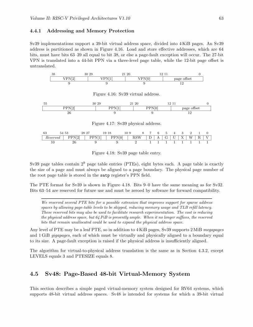
Volume II: RISC-V Privileged Architectures V1.10 63
4.4.1 Addressing and Memory Protection
Sv39 implementations support a 39-bit virtual address space, divided into 4 KiB pages. An Sv39address is partitioned as shown in Figure 4.16. Load and store effective addresses, which are 64bits, must have bits 63–39 all equal to bit 38, or else a page-fault exception will occur. The 27-bitVPN is translated into a 44-bit PPN via a three-level page table, while the 12-bit page offset isuntranslated.
38 30 29 21 20 12 11 0
VPN[2] VPN[1] VPN[0] page offset
9 9 9 12
Figure 4.16: Sv39 virtual address.
55 30 29 21 20 12 11 0
PPN[2] PPN[1] PPN[0] page offset
26 9 9 12
Figure 4.17: Sv39 physical address.
63 54 53 28 27 19 18 10 9 8 7 6 5 4 3 2 1 0
Reserved PPN[2] PPN[1] PPN[0] RSW D A G U X W R V
10 26 9 9 2 1 1 1 1 1 1 1 1
Figure 4.18: Sv39 page table entry.
Sv39 page tables contain 29 page table entries (PTEs), eight bytes each. A page table is exactlythe size of a page and must always be aligned to a page boundary. The physical page number ofthe root page table is stored in the satp register’s PPN field.
The PTE format for Sv39 is shown in Figure 4.18. Bits 9–0 have the same meaning as for Sv32.Bits 63–54 are reserved for future use and must be zeroed by software for forward compatibility.
We reserved several PTE bits for a possible extension that improves support for sparse addressspaces by allowing page-table levels to be skipped, reducing memory usage and TLB refill latency.These reserved bits may also be used to facilitate research experimentation. The cost is reducingthe physical address space, but 64 PiB is presently ample. When it no longer suffices, the reservedbits that remain unallocated could be used to expand the physical address space.
Any level of PTE may be a leaf PTE, so in addition to 4 KiB pages, Sv39 supports 2 MiB megapagesand 1 GiB gigapages, each of which must be virtually and physically aligned to a boundary equalto its size. A page-fault exception is raised if the physical address is insufficiently aligned.
The algorithm for virtual-to-physical address translation is the same as in Section 4.3.2, exceptLEVELS equals 3 and PTESIZE equals 8.
4.5 Sv48: Page-Based 48-bit Virtual-Memory System
This section describes a simple paged virtual-memory system designed for RV64 systems, whichsupports 48-bit virtual address spaces. Sv48 is intended for systems for which a 39-bit virtual
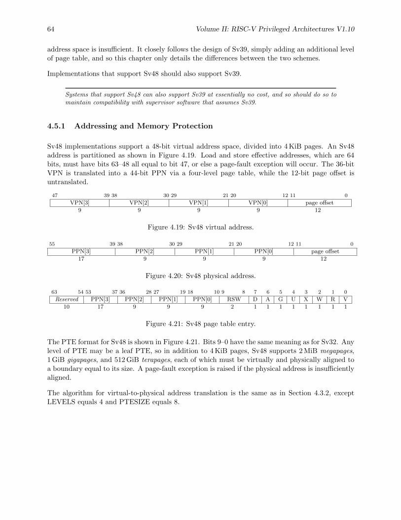
64 Volume II: RISC-V Privileged Architectures V1.10
address space is insufficient. It closely follows the design of Sv39, simply adding an additional levelof page table, and so this chapter only details the differences between the two schemes.
Implementations that support Sv48 should also support Sv39.
Systems that support Sv48 can also support Sv39 at essentially no cost, and so should do so tomaintain compatibility with supervisor software that assumes Sv39.
4.5.1 Addressing and Memory Protection
Sv48 implementations support a 48-bit virtual address space, divided into 4 KiB pages. An Sv48address is partitioned as shown in Figure 4.19. Load and store effective addresses, which are 64bits, must have bits 63–48 all equal to bit 47, or else a page-fault exception will occur. The 36-bitVPN is translated into a 44-bit PPN via a four-level page table, while the 12-bit page offset isuntranslated.
47 39 38 30 29 21 20 12 11 0
VPN[3] VPN[2] VPN[1] VPN[0] page offset
9 9 9 9 12
Figure 4.19: Sv48 virtual address.
55 39 38 30 29 21 20 12 11 0
PPN[3] PPN[2] PPN[1] PPN[0] page offset
17 9 9 9 12
Figure 4.20: Sv48 physical address.
63 54 53 37 36 28 27 19 18 10 9 8 7 6 5 4 3 2 1 0
Reserved PPN[3] PPN[2] PPN[1] PPN[0] RSW D A G U X W R V
10 17 9 9 9 2 1 1 1 1 1 1 1 1
Figure 4.21: Sv48 page table entry.
The PTE format for Sv48 is shown in Figure 4.21. Bits 9–0 have the same meaning as for Sv32. Anylevel of PTE may be a leaf PTE, so in addition to 4 KiB pages, Sv48 supports 2 MiB megapages,1 GiB gigapages, and 512 GiB terapages, each of which must be virtually and physically aligned toa boundary equal to its size. A page-fault exception is raised if the physical address is insufficientlyaligned.
The algorithm for virtual-to-physical address translation is the same as in Section 4.3.2, exceptLEVELS equals 4 and PTESIZE equals 8.
Chapter 5
Hypervisor Extensions, Version 0.0
This chapter is a placeholder for RISC-V hypervisor support with an extended S-mode.
The privileged architecture is designed to simplify the use of classic virtualization techniques,where a guest OS is run at user-level, as the few privileged instructions can be easily detectedand trapped.
65

66 Volume II: RISC-V Privileged Architectures V1.10
Chapter 6
RISC-V Privileged Instruction SetListings
This chapter presents instruction set listings for all instructions defined in the RISC-V PrivilegedArchitecture.
67
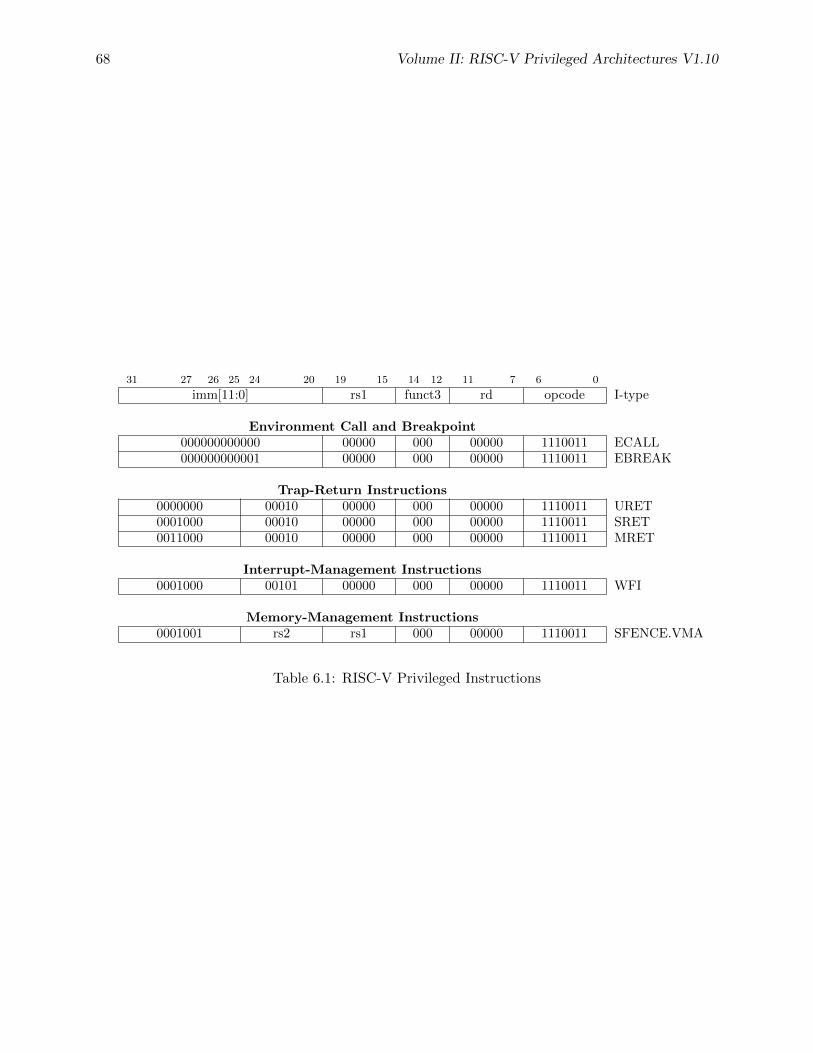
68 Volume II: RISC-V Privileged Architectures V1.10
31 27 26 25 24 20 19 15 14 12 11 7 6 0
imm[11:0] rs1 funct3 rd opcode I-type
Environment Call and Breakpoint000000000000 00000 000 00000 1110011 ECALL000000000001 00000 000 00000 1110011 EBREAK
Trap-Return Instructions0000000 00010 00000 000 00000 1110011 URET0001000 00010 00000 000 00000 1110011 SRET0011000 00010 00000 000 00000 1110011 MRET
Interrupt-Management Instructions0001000 00101 00000 000 00000 1110011 WFI
Memory-Management Instructions0001001 rs2 rs1 000 00000 1110011 SFENCE.VMA
Table 6.1: RISC-V Privileged Instructions
Chapter 7
Platform-Level Interrupt Controller(PLIC)
This chapter describes the general architecture for the RISC-V platform-level interrupt controller(PLIC), which prioritizes and distributes global interrupts in a RISC-V system.
7.1 PLIC Overview
Figure 7.1 provides a quick overview of PLIC operation. The PLIC connects global interruptsources, which are usually I/O devices, to interrupt targets, which are usually hart contexts. ThePLIC contains multiple interrupt gateways, one per interrupt source, together with a PLIC corethat performs interrupt prioritization and routing. Global interrupts are sent from their sourceto an interrupt gateway that processes the interrupt signal from each source and sends a singleinterrupt request to the PLIC core, which latches these in the core interrupt pending bits (IP).Each interrupt source is assigned a separate priority. The PLIC core contains a matrix of interruptenable (IE) bits to select the interrupts that are enabled for each target. The PLIC core forwardsan interrupt notification to one or more targets if the targets have any pending interrupts enabled,and the priority of the pending interrupts exceeds a per-target threshold. When the target takesthe external interrupt, it sends an interrupt claim request to retrieve the identifier of the highest-priority global interrupt source pending for that target from the PLIC core, which then clears thecorresponding interrupt source pending bit. After the target has serviced the interrupt, it sendsthe associated interrupt gateway an interrupt completion message and the interrupt gateway cannow forward another interrupt request for the same source to the PLIC. The rest of this chapterdescribes each of these components in detail, though many details are necessarily platform specific.
7.2 Interrupt Sources
RISC-V harts can have both local and global interrupt sources. Only global interrupt sources arehandled by the PLIC.
69
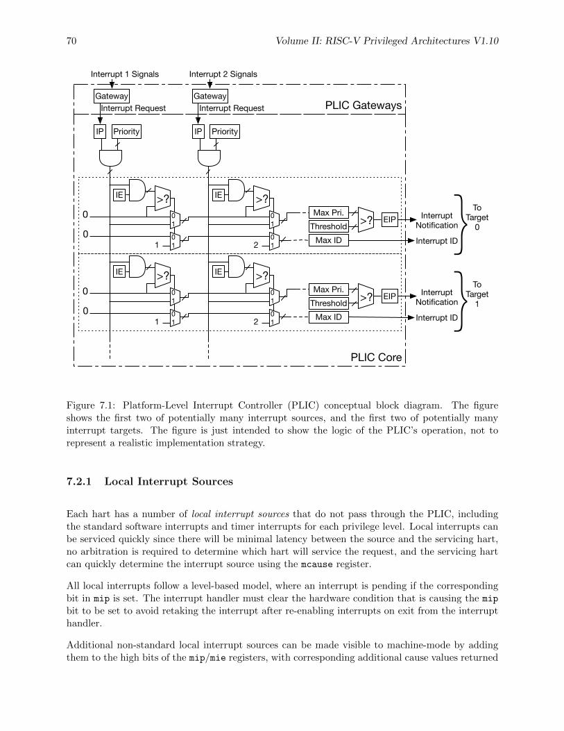
70 Volume II: RISC-V Privileged Architectures V1.10
Gateway
PriorityIP
Interrupt Request
Interrupt 2 Signals
Gateway
PriorityIP
Interrupt Request
Interrupt 1 Signals
PLIC Core
PLIC Gateways
0
0 Max IDThresholdMax Pri.
EIP>? EIP Interrupt Notification
Interrupt ID}To Target
0
IE >?
101
01
IE >?
201
01
0
0 Max IDThresholdMax Pri.
EIP>? EIP Interrupt Notification
Interrupt ID}To Target
1
IE >?
101
01
IE >?
201
01
Figure 7.1: Platform-Level Interrupt Controller (PLIC) conceptual block diagram. The figureshows the first two of potentially many interrupt sources, and the first two of potentially manyinterrupt targets. The figure is just intended to show the logic of the PLIC’s operation, not torepresent a realistic implementation strategy.
7.2.1 Local Interrupt Sources
Each hart has a number of local interrupt sources that do not pass through the PLIC, includingthe standard software interrupts and timer interrupts for each privilege level. Local interrupts canbe serviced quickly since there will be minimal latency between the source and the servicing hart,no arbitration is required to determine which hart will service the request, and the servicing hartcan quickly determine the interrupt source using the mcause register.
All local interrupts follow a level-based model, where an interrupt is pending if the correspondingbit in mip is set. The interrupt handler must clear the hardware condition that is causing the mip
bit to be set to avoid retaking the interrupt after re-enabling interrupts on exit from the interrupthandler.
Additional non-standard local interrupt sources can be made visible to machine-mode by addingthem to the high bits of the mip/mie registers, with corresponding additional cause values returned
Volume II: RISC-V Privileged Architectures V1.10 71
in the mcause register. These additional non-standard local interrupts may also be made visibleto lower privilege levels, using the corresponding bits in the mideleg register. The priority of non-standard local interrupt sources relative to external, timer, and software interrupts is platform-specific.
7.2.2 Global Interrupt Sources
Global interrupt sources are those that are prioritized and distributed by the PLIC. Depending onthe platform-specific PLIC implementation, any global interrupt source could be routed to any hartcontext.
Global interrupt sources can take many forms, including level-triggered, edge-triggered, andmessage-signalled. Some sources might queue up a number of interrupt requests. All global inter-rupt sources are converted to a common interrupt request format for the PLIC.
7.3 Interrupt Targets and Hart Contexts
Interrupt targets are usually hart contexts, where a hart context is a given privilege mode on agiven hart (though there are other possible interrupt targets, such as DMA engines). Not all hartcontexts need be interrupt targets, in particular, if a processor core does not support delegatingexternal interrupts to lower-privilege modes, then the lower-privilege hart contexts will not beinterrupt targets. Interrupt notifications generated by the PLIC appear in the meip/seip/ueipbits of the mip/sip/uip registers for M/S/U modes respectively. The notifications only appear inlower-privilege xip registers if external interrupts have been delegated to the lower-privilege modes.
Each processor core must define a policy on how simultaneous active interrupts are taken bymultiple hart contexts on the core. For the simple case of a single stack of hart contexts, onefor each supported privileged mode, interrupts for higher-privilege contexts can preempt executionof interrupt handlers for lower-privilege contexts. A multithreaded processor core could run multipleindependent interrupt handlers on different hart contexts at the same time. A processor core couldalso provide hart contexts that are only used for interrupt handling to reduce interrupt servicelatency, and these might preempt interrupt handlers for other harts on the same core.
The PLIC treats each interrupt target independently and does not take into account any interruptprioritization scheme used by a component that contains multiple interrupt targets. As a result,the PLIC provides no concept of interrupt preemption or nesting so this must be handled by thecores hosting multiple interrupt target contexts.
7.4 Interrupt Gateways
The interrupt gateways are responsible for converting global interrupt signals into a common inter-rupt request format, and for controlling the flow of interrupt requests to the PLIC core. At mostone interrupt request per interrupt source can be pending in the PLIC core at any time, indicatedby setting the source’s IP bit. The gateway only forwards a new interrupt request to the PLIC
72 Volume II: RISC-V Privileged Architectures V1.10
core after receiving notification that the interrupt handler servicing the previous interrupt requestfrom the same source has completed.
If the global interrupt source uses level-sensitive interrupts, the gateway will convert the firstassertion of the interrupt level into an interrupt request, but thereafter the gateway will not forwardan additional interrupt request until it receives an interrupt completion message. On receiving aninterrupt completion message, if the interrupt is level-triggered and the interrupt is still asserted, anew interrupt request will be forwarded to the PLIC core. The gateway does not have the facilityto retract an interrupt request once forwarded to the PLIC core. If a level-sensitive interrupt sourcedeasserts the interrupt after the PLIC core accepts the request and before the interrupt is serviced,the interrupt request remains present in the IP bit of the PLIC core and will be serviced by ahandler, which will then have to determine that the interrupt device no longer requires service.
If the global interrupt source was edge-triggered, the gateway will convert the first matching signaledge into an interrupt request. Depending on the design of the device and the interrupt handler,inbetween sending an interrupt request and receiving notice of its handler’s completion, the gatewaymight either ignore additional matching edges or increment a counter of pending interrupts. Ineither case, the next interrupt request will not be forwarded to the PLIC core until the previouscompletion message has been received. If the gateway has a pending interrupt counter, the counterwill be decremented when the interrupt request is accepted by the PLIC core.
Unlike dedicated-wire interrupt signals, message-signalled interrupts (MSIs) are sent over the sys-tem interconnect via a message packet that describes which interrupt is being asserted. The messageis decoded to select an interrupt gateway, and the relevant gateway then handles the MSI similarto an edge-triggered interrupt.
7.5 Interrupt Identifiers (IDs)
Global interrupt sources are assigned small unsigned integer identifiers, beginning at the value 1.An interrupt ID of 0 is reserved to mean “no interrupt”.
Interrupt identifiers are also used to break ties when two or more interrupt sources have the sameassigned priority. Smaller values of interrupt ID take precedence over larger values of interrupt ID.
7.6 Interrupt Priorities
Interrupt priorities are small unsigned integers, with a platform-specific maximum number of sup-ported levels. The priority value 0 is reserved to mean “never interrupt”, and interrupt priorityincreases with increasing integer values.
Each global interrupt source has an associated interrupt priority held in a platform-specific memory-mapped register. Different interrupt sources need not support the same set of priority values. Avalid implementation can hardwire all input priority levels. Interrupt source priority registersshould be WARL fields to allow software to determine the number and position of read-writebits in each priority specification, if any. To simplify discovery of supported priority values, each
Volume II: RISC-V Privileged Architectures V1.10 73
priority register must support any combination of values in the bits that are variable within theregister, i.e., if there are two variable bits in the register, all four combinations of values in thosebits must operate as valid priority levels.
In the degenerate case, all priorities can be hardwired to the value 1, in which case input prioritiesare effectively determined by interrupt ID.
The supported priority values can be determined as follows: 1) write all zeros to the priorityregister then 2) read back the value. Any set bits are hardwired to 1. Next, 3) write all onesto the register, and 4) read back the value. Any clear bits are hardwired to 0. Any set bits thatwere not found to be hardwired in step 2 are variable. The supported priority levels are the setof values obtained by substituting all combinations of ones and zeros in the variable bits withinthe priority field.
7.7 Interrupt Enables
Each target has a vector of interrupt enable (IE) bits, one per interrupt source. The target willnot receive interrupts from sources that are disabled. The IE bits for a single target should bepacked together as a bit vector in platform-specific memory-mapped control registers to supportrapid context switching of the IE bits for a target. IE bits are WARL fields that can be hardwiredto either 0 or 1.
A large number of potential IE bits might be hardwired to zero in cases where some interruptsources can only be routed to a subset of targets.
A larger number of bits might be wired to 1 for an embedded device with fixed interrupt rout-ing. Interrupt priorities, thresholds, and hart-internal interrupt masking provide considerableflexibility in ignoring external interrupts even if a global interrupt source is always enabled.
7.8 Interrupt Priority Thresholds
Each interrupt target has an associated priority threshold, held in a platform-specific memory-mapped register. Only active interrupts that have a priority strictly greater than the thresholdwill cause a interrupt notification to be sent to the target. Different interrupt targets need notsupport the same set of priority threshold values. Interrupt target threshold registers should beWARL fields to allow software to determine the supported thresholds. A threshold register shouldalways be able to hold the value zero, in which case, no interrupts are masked. If implemented,the threshold register will usually also be able to hold the maximum priority level, in which caseall interrupts are masked.
A simple valid implementation is to hardwire the threshold to zero, in which case it has no effect,and the individual enable bits will have to be saved and restored to attain the same effect. Whilethe function of the threshold can be achieved by changing the interrupt-enable bits, manipulatinga single threshold value avoids the target having to consider the individual priority levels of eachinterrupt source, and saving and restoring all the interrupt enables. Changing the thresholdquickly might be especially important for systems that move frequently between power states.
74 Volume II: RISC-V Privileged Architectures V1.10
7.9 Interrupt Notifications
Each interrupt target has an external interrupt pending (EIP) bit in the PLIC core that indicatesthat the corresponding target has a pending interrupt waiting for service. The value in EIP canchange as a result of changes to state in the PLIC core, brought on by interrupt sources, interrupttargets, or other agents manipulating register values in the PLIC. The value in EIP is communicatedto the destination target as an interrupt notification. If the target is a RISC-V hart context, theinterrupt notifications arrive on the meip/seip/ueip bits depending on the privilege level of thehart context.
In simple systems, the interrupt notifications will be simple wires connected to the processorimplementing a hart. In more complex platforms, the notifications might be routed as messagesacross a system interconnect.
The PLIC hardware only supports multicasting of interrupts, such that all enabled targets willreceive interrupt notifications for a given active interrupt.
Multicasting provides rapid response since the fastest responder claims the interrupt, but can bewasteful in high-interrupt-rate scenarios if multiple harts take a trap for an interrupt that onlyone can successfully claim. Software can modulate the PLIC IE bits as part of each interrupthandler to provide alternate policies, such as interrupt affinity or round-robin unicasting.
Depending on the platform architecture and the method used to transport interrupt notifications,these might take some time to be received at the targets. The PLIC is guaranteed to eventuallydeliver all state changes in EIP to all targets, provided there is no intervening activity in the PLICcore.
The value in an interrupt notification is only guaranteed to hold an EIP value that was valid atsome point in the past. In particular, a second target can respond and claim an interrupt whilea notification to the first target is still in flight, such that when the first target tries to claim theinterrupt it finds it has no active interrupts in the PLIC core.
7.10 Interrupt Claims
Sometime after a target receives an interrupt notification, it might decide to service the interrupt.The target sends an interrupt claim message to the PLIC core, which will usually be implementedas a non-idempotent memory-mapped I/O control register read. On receiving a claim message, thePLIC core will atomically determine the ID of the highest-priority pending interrupt for the targetand then clear down the corresponding source’s IP bit. The PLIC core will then return the ID tothe target. The PLIC core will return an ID of zero, if there were no pending interrupts for thetarget when the claim was serviced.
After the highest-priority pending interrupt is claimed by a target and the corresponding IP bitis cleared, other lower-priority pending interrupts might then become visible to the target, and sothe PLIC EIP bit might not be cleared after a claim. The interrupt handler can check the localmeip/seip/ueip bits before exiting the handler, to allow more efficient service of other interruptswithout first restoring the interrupted context and taking another interrupt trap.
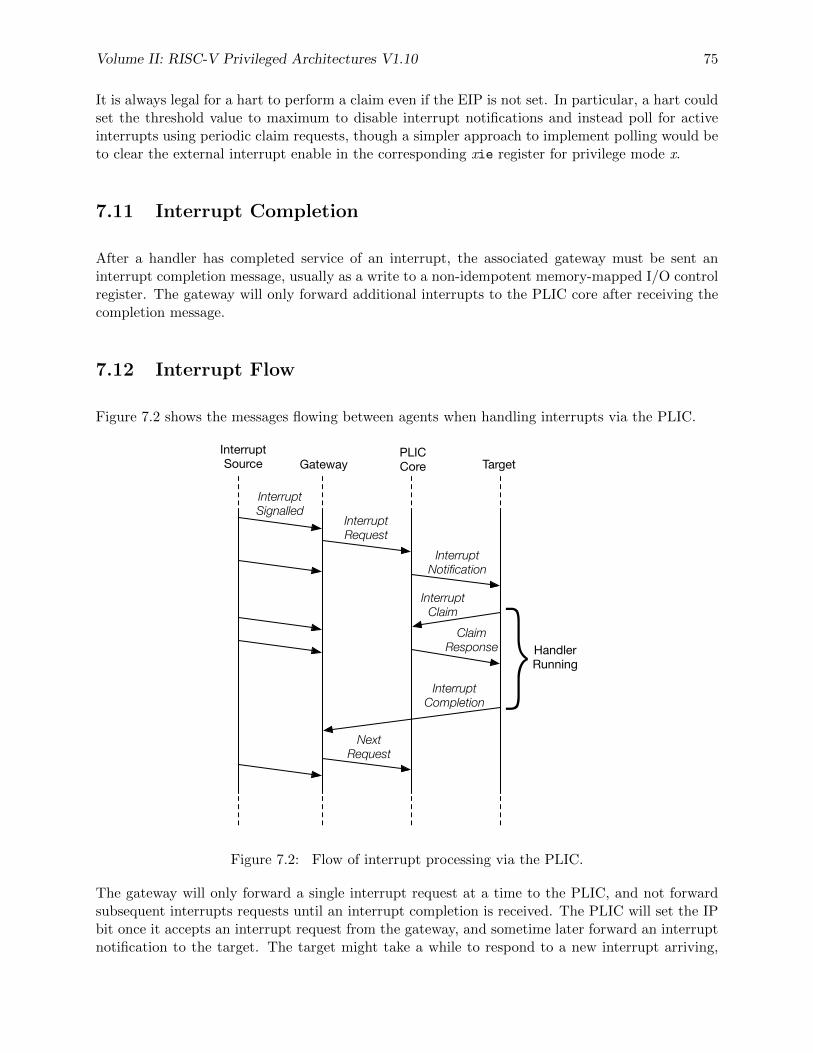
Volume II: RISC-V Privileged Architectures V1.10 75
It is always legal for a hart to perform a claim even if the EIP is not set. In particular, a hart couldset the threshold value to maximum to disable interrupt notifications and instead poll for activeinterrupts using periodic claim requests, though a simpler approach to implement polling would beto clear the external interrupt enable in the corresponding xie register for privilege mode x.
7.11 Interrupt Completion
After a handler has completed service of an interrupt, the associated gateway must be sent aninterrupt completion message, usually as a write to a non-idempotent memory-mapped I/O controlregister. The gateway will only forward additional interrupts to the PLIC core after receiving thecompletion message.
7.12 Interrupt Flow
Figure 7.2 shows the messages flowing between agents when handling interrupts via the PLIC.
Interrupt Source Gateway
PLIC Core Target
Interrupt Request
Interrupt Notification
Interrupt Claim
Claim Response
Interrupt Signalled
Interrupt Completion
Next Request
}Handler Running
Figure 7.2: Flow of interrupt processing via the PLIC.
The gateway will only forward a single interrupt request at a time to the PLIC, and not forwardsubsequent interrupts requests until an interrupt completion is received. The PLIC will set the IPbit once it accepts an interrupt request from the gateway, and sometime later forward an interruptnotification to the target. The target might take a while to respond to a new interrupt arriving,
76 Volume II: RISC-V Privileged Architectures V1.10
but will then send an interrupt claim request to the PLIC core to obtain the interrupt ID. ThePLIC core will atomically return the ID and clear the corresponding IP bit, after which no othertarget can claim the same interrupt request. Once the handler has processed the interrupt, it sendsan interrupt completion message to the gateway to allow a new interrupt request.
7.13 PLIC Core Specification
The operation of the PLIC core can be specified as a non-deterministic finite-state machine withinput and output message queues, with the following atomic actions:
• Write Register: A message containing a register write request is dequeued. One of theinternal registers is written, where an internal register can be a priority, an interrupt-enable(IE), or a threshold.
• Accept Request: If the IP bit corresponding to the interrupt source is clear, a messagecontaining an interrupt request from a gateway is dequeued and the IP bit is set.
• Process Claim: An interrupt claim message is dequeued. A claim-response message isenqueued to the requester with the ID of the highest-priority active interrupt for that target,and the IP bit corresponding to this interrupt source is cleared.
The value in the EIP bit is determined as a combinational function of the PLIC Core state. Interruptnotifications are sent via an autonomous process that ensures the EIP value is eventually reflectedat the target.
Note that the operation of the interrupt gateways is decoupled from the PLIC core. A gatewaycan handle parsing of interrupt signals and processing interrupt completion messages concurrentlywith other operations in the PLIC core.
Figure 7.1 is a high-level conceptual view of the PLIC design. The PLIC core can be implementedin many ways provided its behavior can always be understood as following from some sequentialordering of these atomic actions. In particular, the PLIC might process multiple actions in asingle clock cycle, or might process each action over many clock cycles.
7.14 Controlling Access to the PLIC
In the expected use case, only machine mode accesses the source priority, source pending, andtarget interrupt enables to configure the interrupt subsystem. Lower-privilege modes access thesefeatures via ABI or SBI calls. The interrupt enables act as a protection mechanism where a targetcan only signal completion to an interrupt gateway that is currently enabled for that target.
Interrupt handlers that run with lower than machine-mode privilege need only be able to performa claim read and a completion write, and to set their target threshold value. The memory map forthese registers should allow machine mode to protect different targets from each other’s accesses,using either physical memory protection or virtual memory page protections.
Chapter 8
Machine Configuration Description
To reduce porting effort for OS boots, we have reverted back to using Device Trees to communicateplatform information to the kernel, so this chapter is out of date. Config string was designedfor other uses in addition, but for now, we are staying with a standard device tree model.
RISC-V platforms may contain myriad devices, processor cores, and configuration parameters. Tosupport higher-level software, including bootloaders and operating systems, it is recommended thathardware platforms embed a description of their components in read-only memory that is directlyaccessible after processor reset for use by low-level system software, external debuggers, or manu-facturing test procedures. We call this low-level embedded information a configuration description.We define here a standard mechanism to encode and locate the configuration information, and todetermine the format of the configuration information.
8.1 Configuration String Search Procedure
The platform must describe how to locate a pointer to find this string, for example, by specifyinga fixed physical address at which the pointer resides. To support a wide variety of platforms,configuration formats, and chips with manufacturing-time programming of configuration options,a flexible search procedure is defined to locate the configuration information seeded by the initialpointer specified by the platform.
The configuration string pointer provided by the platform points to an initial memory address atwhich the search for configuration string begins.
The configuration string cannot begin with a padding byte, where a padding byte is defined tocontain either 0x0 or 0xff, but can be preceded by up to 63 padding bytes that are ignored. If 64padding bytes are encountered, then the search terminates without finding a config string.
The padding bytes represent common values returned by unpopulated memory or bus regionsor unprogrammed non-volatile memory. Configuration strings can therefore include pointers toregions that are optionally populated or programmed, and these regions will be ignored if thereis nothing present. The padding bytes also support alignment of binary data structures.
Otherwise the first non-padding byte is the beginning of the configuration information. For ex-ample, configuration information in Device Tree String format would begin with a “/dts-v1/”.
77
78 Volume II: RISC-V Privileged Architectures V1.10
Configuration information in Flattened Device Tree format would begin with the magic number0xd00dfeed. Configuration information in the config string format would begin with “/cs-v1/”.
Config string is a new format that is backwards-compatible with device tree string (as far as DTSspecs exist) but can include additional configuration information in other memory regions.
Chapter 9
History
9.1 Research Funding at UC Berkeley
Development of the RISC-V architecture and implementations has been partially funded by thefollowing sponsors.
• Par Lab: Research supported by Microsoft (Award #024263) and Intel (Award #024894)funding and by matching funding by U.C. Discovery (Award #DIG07-10227). Additionalsupport came from Par Lab affiliates Nokia, NVIDIA, Oracle, and Samsung.
• Project Isis: DoE Award DE-SC0003624.
• ASPIRE Lab: DARPA PERFECT program, Award HR0011-12-2-0016. DARPA POEMprogram Award HR0011-11-C-0100. The Center for Future Architectures Research (C-FAR),a STARnet center funded by the Semiconductor Research Corporation. Additional sup-port from ASPIRE industrial sponsor, Intel, and ASPIRE affiliates, Google, Huawei, Nokia,NVIDIA, Oracle, and Samsung.
The content of this paper does not necessarily reflect the position or the policy of the US governmentand no official endorsement should be inferred.
79

80 Volume II: RISC-V Privileged Architectures V1.10
Bibliography
[1] Robert P. Goldberg. Survey of virtual machine research. Computer, 7(6):34–45, June 1974.
[2] Juan Navarro, Sitararn Iyer, Peter Druschel, and Alan Cox. Practical, transparent operatingsystem support for superpages. SIGOPS Oper. Syst. Rev., 36(SI):89–104, December 2002.
81