Embed Size (px)
Citation preview
nce ofthree
uringringed byht tod to. Per-h airmancefor ae im-th theand-lithic
N. A. Fleck1
e-mail: [email protected]
V. S. Deshpande
Engineering Department,Cambridge University,
Trumpington Street,Cambridge, CB2 1PZ, UK
The Resistance of ClampedSandwich Beams to ShockLoadingA systematic design procedure has been developed for analyzing the blast resistaclamped sandwich beams. The structural response of the sandwich beam is split intosequential steps: stage I is the one-dimensional fluid-structure interaction problem dthe blast loading event, and results in a uniform velocity of the outer face sheet; dustage II the core crushes and the velocities of the faces and core become equalizmomentum sharing; stage III is the retardation phase over which the beam is brougrest by plastic bending and stretching. The third-stage analytical procedure is useobtain the dynamic response of a clamped sandwich beam to an imposed impulseformance charts for a wide range of sandwich core topologies are constructed for botand water blast, with the monolithic beam taken as the reference case. These perforcharts are used to determine the optimal geometry to maximize blast resistancegiven mass of sandwich beam. For the case of water blast, an order of magnitudprovement in blast resistance is achieved by employing sandwich construction, widiamond-celled core providing the best blast performance. However, in air blast, swich construction gives only a moderate gain in blast resistance compared to monoconstruction.@DOI: 10.1115/1.1629109#
ao
t
e
ao
mn
i
id-utertheer-theat of
ex-iledUse-
pin
erts
n
f ar thecehe-ith ays-xplo-sto the
sivehaveaginglo-
n,
1 IntroductionA major consideration in the design of military vehicles~such
as ships and aircraft! is their resistance to air and water blasEarly work ~at the time of World War II! focused on monolithicplates, and involved measurement of blast resistance by full stesting for a limited range of materials and geometries. Simanalytical models were also developed, such as the odimensional fluid-structure interaction model of Taylor@1#.
Over the last decade a number of new core topologies for swich panels have emerged, showing structural advantagemonolithic construction for quasi-static loadings. These inclumetallic foams,@2#, lattice materials of pyramidal and tetrahedrarrangement,@3#, woven material,@4#, and egg-box,@5#. The cur-rent study is an attempt to extend and to synthesize analymodels for the dynamic response of clamped beams in ordeoptimize the blast resistance of clamped sandwich beams. Expcomparisons are made between the performance of compcore concepts.
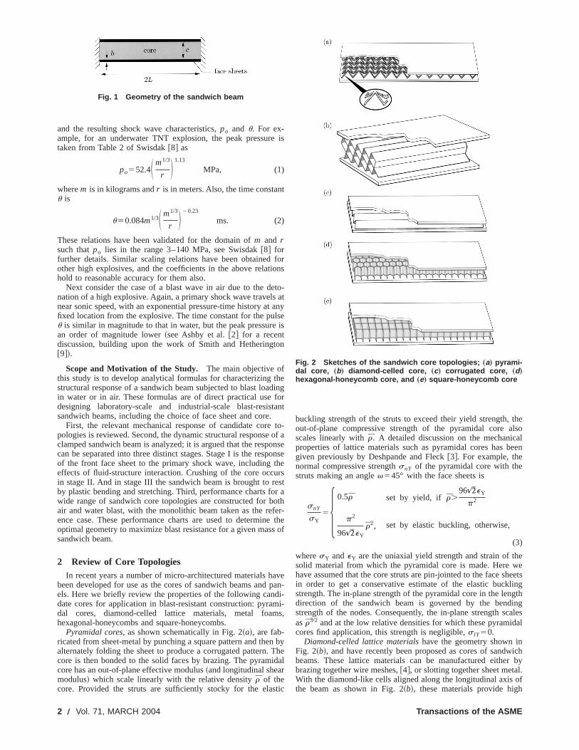
The clamped sandwich beams, as sketched in Fig. 1, is resentative of that used in the design of commercial and militvehicles: For example, the outermost structure on a ship cprizes plates welded to an array of stiffeners. While it is appreated that the precise dynamic response of plates is different fthat explored here for beams, the qualitative details will be silar, and major simplifications arise from the fact that simple alytical formulas can be derived for the beam.
In a parallel study, Xue and Hutchinson@6# have compared theblast resistance of clamped sandwich beams to that of monolbeams of the same mass via three-dimensional finite element~FE!simulations. In these FE calculations, Xue and Hutchinson@6#
1To whom correspondence should be addressed.Contributed by the Applied Mechanics Division of THE AMERICAN SOCIETY OF
MECHANICAL ENGINEERSfor publication in the ASME JOURNAL OF APPLIED ME-CHANICS. Manuscript received by the ASME Applied Mechanics Division, May 12002; final revision, July 10, 2003. Associate Editor: R. M. McMeeking, Discusson the paper should be addressed to the Editor, Prof. Robert M. McMeeking, Dement of Mechanical and Environmental Engineering University of California—SaBarbara, Santa Barbara, CA 93106-5070, and will be accepted until four monthsfinal publication of the paper itself in the ASME JOURNAL OF APPLIED MECHAN-ICS.
Copyright © 2Journal of Applied Mechanics
t.
caleplene-
nd-ver
deal
icalr tolicitting
pre-rym-ci-rom
i-a-
thic
modeled the core topologies explicitly but ignored the flustructure interaction; a prescribed impulse was applied to the oface of the sandwich beam and was applied uniformly tomonolithic beam. A limited number of FE calculations were pformed to identify near-optimal sandwich configurations, andsuperior blast resistance of sandwich beams compared to thmonolithic beams was demonstrated.
Review of the Characteristics of a Water Blast. The maincharacteristics of a shock wave resulting from an underwaterplosion are well established due to a combination of detalarge-scale experiments and modeling over the past 60 years.ful summaries of the main phenomena are provided by Cole@7#and Swisdak@8#, and are repeated briefly here in order to underthe current study.
The underwater detonation of a high explosive charge convthe solid explosive material into gaseous reaction products~on atime scale,t, of microseconds!. The reaction products are at aenormous pressure~on the order of GPa!, and this pressure istransmitted to the surrounding water by the propagation ospherical shock wave at approximately sonic speed. Consideresponse of a representative fluid element at a radial distanrfrom the explosion. Upon arrival of the primary shock wave, tpressure rises to a peak valuepo almost instantaneously. Subsequently, the pressure decreases at a nearly exponential rate, wtime constantu on the order of milliseconds, and is given bp(t)5po exp(2t/u). The magnitude of the shock wave peak presure and decay constant depend upon the mass and type of esive material and the distancer . After the primary shock wave hapassed, subsequent secondary shocks are experienced, duedamped oscillation of the gas bubble which contains the exploreaction products. However, these secondary shock wavesmuch smaller peak pressures, and are usually much less damthan the primary shock to a structure in the vicinity of the expsion than the primary shock.
Experimental data~and physical models! support the use ofsimple power-law scaling relations between the massm of explo-sive, the separationr between explosion and point of observatio
9,ionpart-ntaafter
004 by ASME MARCH 2004, Vol. 71 Õ 1
e
i
e
e
t
tueo
d
s
thelsoaleen
eweheetslinggthingales
dal
ichr byl.of
and the resulting shock wave characteristics,po and u. For ex-ample, for an underwater TNT explosion, the peak pressurtaken from Table 2 of Swisdak@8# as
po552.4S m1/3
r D 1.13
MPa, (1)
wherem is in kilograms andr is in meters. Also, the time constanu is
u50.084m1/3S m1/3
r D 20.23
ms. (2)
These relations have been validated for the domain ofm and rsuch thatpo lies in the range 3–140 MPa, see Swisdak@8# forfurther details. Similar scaling relations have been obtainedother high explosives, and the coefficients in the above relathold to reasonable accuracy for them also.
Next consider the case of a blast wave in air due to the dnation of a high explosive. Again, a primary shock wave travelsnear sonic speed, with an exponential pressure-time history atfixed location from the explosive. The time constant for the puu is similar in magnitude to that in water, but the peak pressuran order of magnitude lower~see Ashby et al.@2# for a recentdiscussion, building upon the work of Smith and Hetheringt@9#!.
Scope and Motivation of the Study. The main objective ofthis study is to develop analytical formulas for characterizingstructural response of a sandwich beam subjected to blast loain water or in air. These formulas are of direct practical usedesigning laboratory-scale and industrial-scale blast-resissandwich beams, including the choice of face sheet and core
First, the relevant mechanical response of candidate corepologies is reviewed. Second, the dynamic structural responseclamped sandwich beam is analyzed; it is argued that the respcan be separated into three distinct stages. Stage I is the respof the front face sheet to the primary shock wave, includingeffects of fluid-structure interaction. Crushing of the core occin stage II. And in stage III the sandwich beam is brought to rby plastic bending and stretching. Third, performance charts fwide range of sandwich core topologies are constructed for bair and water blast, with the monolithic beam taken as the reence case. These performance charts are used to determinoptimal geometry to maximize blast resistance for a given massandwich beam.
2 Review of Core TopologiesIn recent years a number of micro-architectured materials h
been developed for use as the cores of sandwich beams andels. Here we briefly review the properties of the following candate cores for application in blast-resistant construction: pyradal cores, diamond-celled lattice materials, metal foamhexagonal-honeycombs and square-honeycombs.
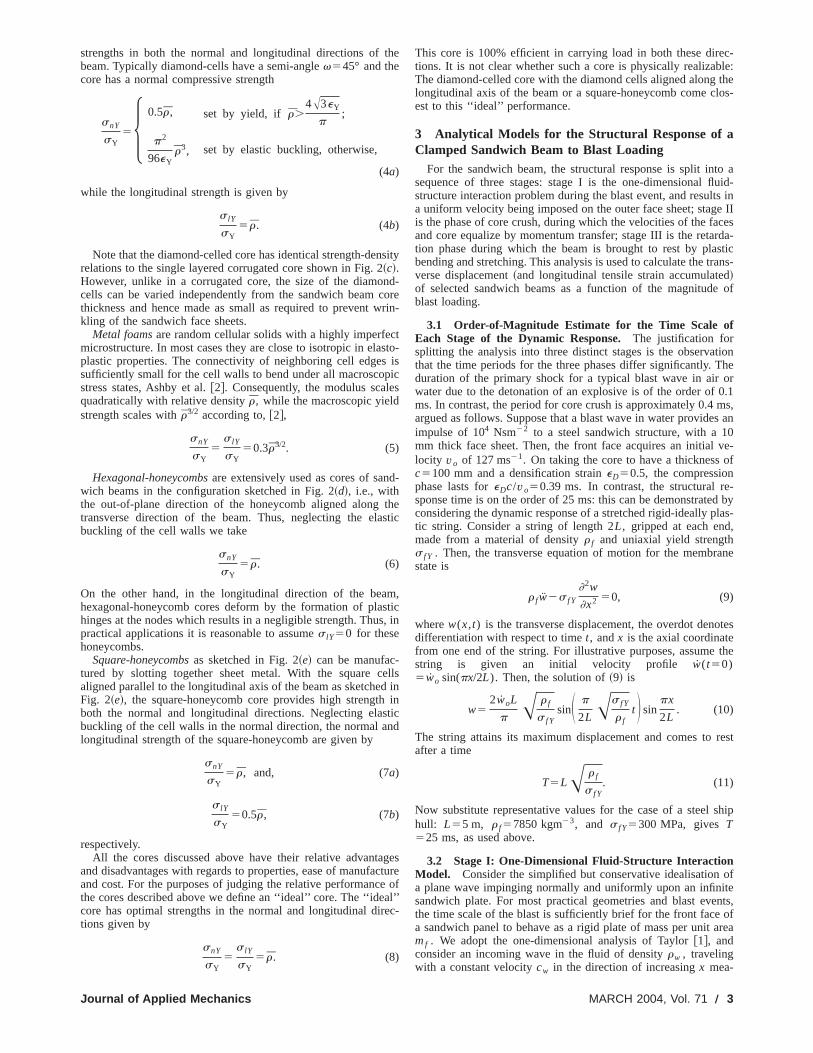
Pyramidal cores, as shown schematically in Fig. 2~a!, are fab-ricated from sheet-metal by punching a square pattern and thealternately folding the sheet to produce a corrugated pattern.core is then bonded to the solid faces by brazing. The pyramcore has an out-of-plane effective modulus~and longitudinal shearmodulus! which scale linearly with the relative densityr of thecore. Provided the struts are sufficiently stocky for the ela
Fig. 1 Geometry of the sandwich beam
2 Õ Vol. 71, MARCH 2004
is
t
forons
to-atany
lseis
on
hedingfortant.
to-of a
onseonsehersstr aothfer-e thes of
avepan-i-
mi-s,
n byTheidal
tic
buckling strength of the struts to exceed their yield strength,out-of-plane compressive strength of the pyramidal core ascales linearly withr. A detailed discussion on the mechanicproperties of lattice materials such as pyramidal cores has bgiven previously by Deshpande and Fleck@3#. For example, thenormal compressive strengthsnY of the pyramidal core with thestruts making an anglev545° with the face sheets is
snY
sY55 0.5r set by yield, if r.
96&eY
p2
p2
96&eY
r2, set by elastic buckling, otherwise,
(3)
wheresY andeY are the uniaxial yield strength and strain of thsolid material from which the pyramidal core is made. Herehave assumed that the core struts are pin-jointed to the face sin order to get a conservative estimate of the elastic buckstrength. The in-plane strength of the pyramidal core in the lendirection of the sandwich beam is governed by the bendstrength of the nodes. Consequently, the in-plane strength scasr3/2 and at the low relative densities for which these pyramicores find application, this strength is negligible,s lY50.
Diamond-celled lattice materialshave the geometry shown inFig. 2~b!, and have recently been proposed as cores of sandwbeams. These lattice materials can be manufactured eithebrazing together wire meshes,@4#, or slotting together sheet metaWith the diamond-like cells aligned along the longitudinal axisthe beam as shown in Fig. 2~b!, these materials provide high
Fig. 2 Sketches of the sandwich core topologies; „a… pyrami-dal core, „b… diamond-celled core, „c… corrugated core, „d…hexagonal-honeycomb core, and „e… square-honeycomb core
Transactions of the ASME
t
ncw
c
pe
t
ss
ed
n
ea
c-le:thelos-
to auid-s ine IIcesrda-sticans-de of
tionhe
or0.1ms,s an0ve-of
-d bylas-,
ane
tes
the
rest
ship
ofitents,ofarea
strengths in both the normal and longitudinal directions ofbeam. Typically diamond-cells have a semi-anglev545° and thecore has a normal compressive strength
snY
sY5H 0.5r, set by yield, if r.
4A3eY
p;
p2
96eYr3, set by elastic buckling, otherwise,
(4a)
while the longitudinal strength is given by
s lY
sY5 r. (4b)
Note that the diamond-celled core has identical strength-denrelations to the single layered corrugated core shown in Fig. 2~c!.However, unlike in a corrugated core, the size of the diamocells can be varied independently from the sandwich beamthickness and hence made as small as required to preventkling of the sandwich face sheets.
Metal foamsare random cellular solids with a highly imperfemicrostructure. In most cases they are close to isotropic in elaplastic properties. The connectivity of neighboring cell edgessufficiently small for the cell walls to bend under all macroscostress states, Ashby et al.@2#. Consequently, the modulus scalquadratically with relative densityr, while the macroscopic yieldstrength scales withr3/2 according to,@2#,
snY
sY5
s lY
sY50.3r3/2. (5)
Hexagonal-honeycombsare extensively used as cores of sanwich beams in the configuration sketched in Fig. 2~d!, i.e., withthe out-of-plane direction of the honeycomb aligned alongtransverse direction of the beam. Thus, neglecting the elabuckling of the cell walls we take
snY
sY5 r. (6)
On the other hand, in the longitudinal direction of the beahexagonal-honeycomb cores deform by the formation of plahinges at the nodes which results in a negligible strength. Thupractical applications it is reasonable to assumes lY50 for thesehoneycombs.
Square-honeycombsas sketched in Fig. 2~e! can be manufac-tured by slotting together sheet metal. With the square caligned parallel to the longitudinal axis of the beam as sketcheFig. 2~e!, the square-honeycomb core provides high strengthboth the normal and longitudinal directions. Neglecting elasbuckling of the cell walls in the normal direction, the normal alongitudinal strength of the square-honeycomb are given by
snY
sY5 r, and, (7a)
s lY
sY50.5r, (7b)
respectively.All the cores discussed above have their relative advanta
and disadvantages with regards to properties, ease of manufaand cost. For the purposes of judging the relative performancthe cores described above we define an ‘‘ideal’’ core. The ‘‘idecore has optimal strengths in the normal and longitudinal dirtions given by
snY
sY5
s lY
sY5 r. (8)
Journal of Applied Mechanics
he
sity
d-orerin-
tsto-isics
d-
hestic
m,tic, in
llsinin
ticd
gescture
ofl’’
ec-
This core is 100% efficient in carrying load in both these diretions. It is not clear whether such a core is physically realizabThe diamond-celled core with the diamond cells aligned alonglongitudinal axis of the beam or a square-honeycomb come cest to this ‘‘ideal’’ performance.
3 Analytical Models for the Structural Response of aClamped Sandwich Beam to Blast Loading
For the sandwich beam, the structural response is split insequence of three stages: stage I is the one-dimensional flstructure interaction problem during the blast event, and resulta uniform velocity being imposed on the outer face sheet; stagis the phase of core crush, during which the velocities of the faand core equalize by momentum transfer; stage III is the retation phase during which the beam is brought to rest by plabending and stretching. This analysis is used to calculate the trverse displacement~and longitudinal tensile strain accumulate!of selected sandwich beams as a function of the magnitudblast loading.
3.1 Order-of-Magnitude Estimate for the Time Scale ofEach Stage of the Dynamic Response.The justification forsplitting the analysis into three distinct stages is the observathat the time periods for the three phases differ significantly. Tduration of the primary shock for a typical blast wave in airwater due to the detonation of an explosive is of the order ofms. In contrast, the period for core crush is approximately 0.4argued as follows. Suppose that a blast wave in water provideimpulse of 104 Nsm22 to a steel sandwich structure, with a 1mm thick face sheet. Then, the front face acquires an initiallocity vo of 127 ms21. On taking the core to have a thicknessc5100 mm and a densification straineD50.5, the compressionphase lasts foreDc/vo50.39 ms. In contrast, the structural response time is on the order of 25 ms: this can be demonstrateconsidering the dynamic response of a stretched rigid-ideally ptic string. Consider a string of length 2L, gripped at each endmade from a material of densityr f and uniaxial yield strengths f Y . Then, the transverse equation of motion for the membrstate is
r f w2s f Y
]2w
]x2 50, (9)
wherew(x,t) is the transverse displacement, the overdot denodifferentiation with respect to timet, andx is the axial coordinatefrom one end of the string. For illustrative purposes, assumestring is given an initial velocity profile w(t50)5wo sin(px/2L). Then, the solution of~9! is
w52woL
pA r f
s f YsinS p
2LAs f Y
r ft D sin
px
2L. (10)
The string attains its maximum displacement and comes toafter a time
T5LA r f
s f Y. (11)
Now substitute representative values for the case of a steelhull: L55 m, r f57850 kgm23, and s f Y5300 MPa, givesT525 ms, as used above.
3.2 Stage I: One-Dimensional Fluid-Structure InteractionModel. Consider the simplified but conservative idealisationa plane wave impinging normally and uniformly upon an infinsandwich plate. For most practical geometries and blast evethe time scale of the blast is sufficiently brief for the front facea sandwich panel to behave as a rigid plate of mass per unitmf . We adopt the one-dimensional analysis of Taylor@1#, andconsider an incoming wave in the fluid of densityrw , travelingwith a constant velocitycw in the direction of increasingx mea-
MARCH 2004, Vol. 71 Õ 3
nc
ne
s
t
t
o
la-s-la-
e
lsee ofd-ticalfaceatthe
last
cel-
heis
tial
,-forpli-
ead-
the
g-
snder-
ip
sured perpendicular to the sandwich panel. The origin is takethe front face of the sandwich panel, and the transverse defleof the face is written asw(t) in terms of time,t. Then, the pres-sure profile for the incoming wave can be taken as
pI~x,t !5poe2 ~ t2x/cw! /u, (12)
upon making the usual assumption of a blast wave of exponeshape and time constantu ~on the order of 0.1 ms, as discussabove!. The magnitude of the peak pressurepo is typically in therange 10–100 MPa, and far exceeds the static collapse prefor the sandwich plate~typically on the order of 1 MPa!.
If the front face were rigid and fixed in space, the reflectwave would read
pr1~x,t !5poe2 ~ t1x/cw! /u, (13)
corresponding to perfect reflection of the wave, traveling in2x direction. But the front face sheet is not fixed: it acceleratesa rigid body with a mass per unit areamf , and moves with avelocity w(t). Consequently, the fluid elements adjacent tofront face possess the common velocityw(t), and a rarefactionwavepr2 , of magnitude
pr2~x,t !52rwcwwS t1x
cwD , (14)
is radiated from the front face. Thus, the net water pressurep(x,t)due to the incoming and reflected waves is
p~x,t !5pI1pr11pr25po@e2 ~ t2x/cw! /u1e2 ~ t1x/cw! /u#
2rwcwwS t1x
cwD . (15)
The front face of the sandwich panel~at x50) is accelerated bythe net pressure acting on it, giving the governing ordinary diffential equation for face motion as
mfw1rwcww52poe2t/u. (16)
Upon imposing the initial conditionsw(0)5w(0)50, and defin-ing the nondimensional measurec[rwcwu/mf , the solution of~16! is
w~ t !52pou2
mf~c21!c@~c21!1e2ct/u2ce2t/u#, (17)
and the pressure distribution follows immediately via~15!. In par-ticular, the pressure on the front face is
p~ t,x50!52poe2t/u22poc
c21@e2t/u2e2ct/u#. (18)
For the case of a liquid containing dissolved gases, the presloading on the front face ceases and the liquid cavitates wp(t,x50)→0, thereby defining the cavitation timetc . Substitu-tion of this condition into~18! provides the simple relation
tc
u5
1
c21ln c, (19)
and the impulse conveyed to the face follows from~17! as
I trans5zI (20a)
where
z[c2 c/c21, (20b)
and I is the maximum achievable impulse given by
I 5E0
`
2poe2t/udt52pou. (21)
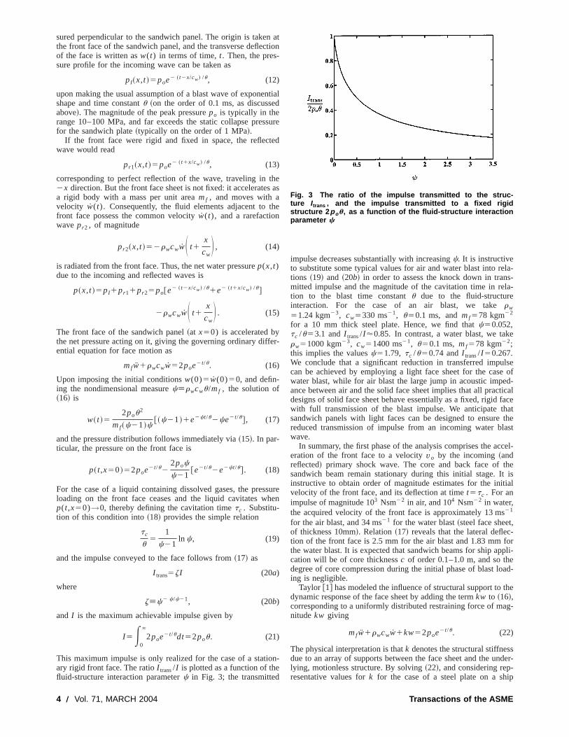
This maximum impulse is only realized for the case of a statiary rigid front face. The ratioI trans/I is plotted as a function of thefluid-structure interaction parameterc in Fig. 3; the transmitted
4 Õ Vol. 71, MARCH 2004
attion
tiald
sure
ed
heas
he
er-
surehen
n-
impulse decreases substantially with increasingc. It is instructiveto substitute some typical values for air and water blast into retions ~19! and ~20b! in order to assess the knock down in tranmitted impulse and the magnitude of the cavitation time in retion to the blast time constantu due to the fluid-structureinteraction. For the case of an air blast, we takerw
51.24 kgm23, cw5330 ms21, u50.1 ms, andmf578 kgm22
for a 10 mm thick steel plate. Hence, we find thatc50.052,tc /u53.1 andI trans/I'0.85. In contrast, a water blast, we takrw51000 kgm23, cw51400 ms21, u50.1 ms, mf578 kgm22;this implies the valuesc51.79, tc /u50.74 andI trans/I 50.267.We conclude that a significant reduction in transferred impucan be achieved by employing a light face sheet for the caswater blast, while for air blast the large jump in acoustic impeance between air and the solid face sheet implies that all pracdesigns of solid face sheet behave essentially as a fixed, rigidwith full transmission of the blast impulse. We anticipate thsandwich panels with light faces can be designed to ensurereduced transmission of impulse from an incoming water bwave.
In summary, the first phase of the analysis comprises the aceration of the front face to a velocityvo by the incoming~andreflected! primary shock wave. The core and back face of tsandwich beam remain stationary during this initial stage. Itinstructive to obtain order of magnitude estimates for the inivelocity of the front face, and its deflection at timet5tc . For animpulse of magnitude 103 Nsm22 in air, and 104 Nsm22 in water,the acquired velocity of the front face is approximately 13 ms21
for the air blast, and 34 ms21 for the water blast~steel face sheetof thickness 10mm!. Relation~17! reveals that the lateral deflection of the front face is 2.5 mm for the air blast and 1.83 mmthe water blast. It is expected that sandwich beams for ship apcation will be of core thicknessc of order 0.1–1.0 m, and so thdegree of core compression during the initial phase of blast loing is negligible.
Taylor @1# has modeled the influence of structural support todynamic response of the face sheet by adding the termkw to ~16!,corresponding to a uniformly distributed restraining force of manitudekw giving
mfw1rwcww1kw52poe2t/u. (22)
The physical interpretation is thatk denotes the structural stiffnesdue to an array of supports between the face sheet and the ulying, motionless structure. By solving~22!, and considering rep-resentative values fork for the case of a steel plate on a sh
Fig. 3 The ratio of the impulse transmitted to the struc-ture Itrans , and the impulse transmitted to a fixed rigidstructure 2 p ou, as a function of the fluid-structure interactionparameter c
Transactions of the ASME
jefi
ho
c
e
l
t
,
e
b
c
gh
to
son-e toef-suf-
ed,uce
unit
on-
sh
hevese
e-
d to
be
superstructure, Taylor demonstrated that the stiffness term caneglected with little attendant loss of accuracy. The main obtive of the current study is to compare the relative performancvarious sandwich panel configurations, and so the simplianalysis is adequate for our purposes.
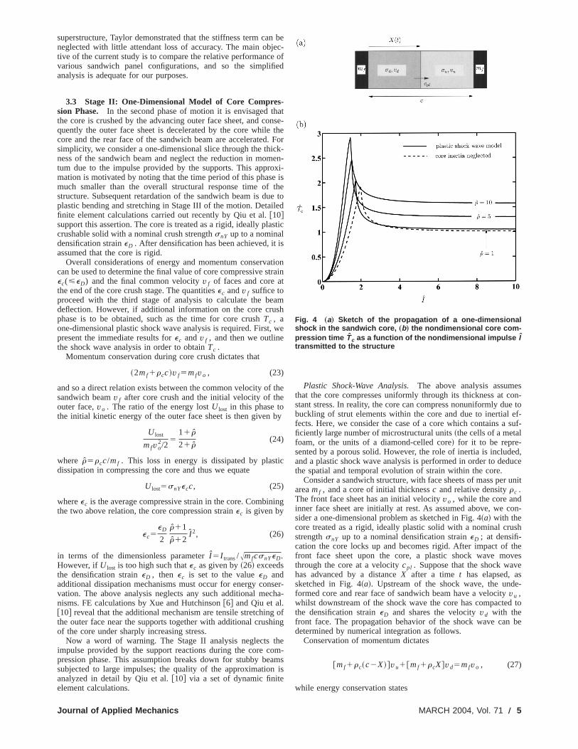
3.3 Stage II: One-Dimensional Model of Core Compres-sion Phase. In the second phase of motion it is envisaged tthe core is crushed by the advancing outer face sheet, and cquently the outer face sheet is decelerated by the core whilecore and the rear face of the sandwich beam are acceleratedsimplicity, we consider a one-dimensional slice through the thiness of the sandwich beam and neglect the reduction in momtum due to the impulse provided by the supports. This appromation is motivated by noting that the time period of this phasmuch smaller than the overall structural response time ofstructure. Subsequent retardation of the sandwich beam is duplastic bending and stretching in Stage III of the motion. Detaifinite element calculations carried out recently by Qiu et al.@10#support this assertion. The core is treated as a rigid, ideally placrushable solid with a nominal crush strengthsnY up to a nominaldensification straineD . After densification has been achieved, itassumed that the core is rigid.
Overall considerations of energy and momentum conservacan be used to determine the final value of core compressive sec(<eD) and the final common velocityv f of faces and core athe end of the core crush stage. The quantitiesec andv f suffice toproceed with the third stage of analysis to calculate the bedeflection. However, if additional information on the core cruphase is to be obtained, such as the time for core crushTc , aone-dimensional plastic shock wave analysis is required. Firstpresent the immediate results forec andv f , and then we outlinethe shock wave analysis in order to obtainTc .
Momentum conservation during core crush dictates that
~2mf1rcc!v f5mfvo , (23)
and so a direct relation exists between the common velocity ofsandwich beamv f after core crush and the initial velocity of thouter face,vo . The ratio of the energy lostU lost in this phase tothe initial kinetic energy of the outer face sheet is then given
U lost
mfvo2/2
511 r
21 r(24)
where r5rcc/mf . This loss in energy is dissipated by plastdissipation in compressing the core and thus we equate
U lost5snYecc, (25)
whereec is the average compressive strain in the core. Combinthe two above relation, the core compression strainec is given by
ec5eD
2
r11
r12I 2, (26)
in terms of the dimensionless parameterI 5I trans/AmfcsnYeD.However, ifU lost is too high such thatec as given by~26! exceedsthe densification straineD , then ec is set to the valueeD andadditional dissipation mechanisms must occur for energy convation. The above analysis neglects any such additional menisms. FE calculations by Xue and Hutchinson@6# and Qiu et al.@10# reveal that the additional mechanism are tensile stretchinthe outer face near the supports together with additional crusof the core under sharply increasing stress.
Now a word of warning. The Stage II analysis neglectsimpulse provided by the support reactions during the core cpression phase. This assumption breaks down for stubby besubjected to large impulses; the quality of the approximationanalyzed in detail by Qiu et al.@10# via a set of dynamic finiteelement calculations.
Journal of Applied Mechanics
n beec-
ofed
atnse-the
. Fork-en-xi-is
thee toed
stic
is
tiontrain
amsh
we
the
y
ic
ing
ser-ha-
ofing
hem-amsis
Plastic Shock-Wave Analysis.The above analysis assumethat the core compresses uniformly through its thickness at cstant stress. In reality, the core can compress nonuniformly dubuckling of strut elements within the core and due to inertialfects. Here, we consider the case of a core which contains aficiently large number of microstructural units~the cells of a metalfoam, or the units of a diamond-celled core! for it to be repre-sented by a porous solid. However, the role of inertia is includand a plastic shock wave analysis is performed in order to dedthe spatial and temporal evolution of strain within the core.
Consider a sandwich structure, with face sheets of mass perareamf , and a core of initial thicknessc and relative densityrc .The front face sheet has an initial velocityvo , while the core andinner face sheet are initially at rest. As assumed above, we csider a one-dimensional problem as sketched in Fig. 4~a! with thecore treated as a rigid, ideally plastic solid with a nominal crustrengthsnY up to a nominal densification straineD ; at densifi-cation the core locks up and becomes rigid. After impact of tfront face sheet upon the core, a plastic shock wave mothrough the core at a velocitycpl . Suppose that the shock wavhas advanced by a distanceX after a time t has elapsed, assketched in Fig. 4~a!. Upstream of the shock wave, the undformed core and rear face of sandwich beam have a velocityvu ,whilst downstream of the shock wave the core has compactethe densification straineD and shares the velocityvd with thefront face. The propagation behavior of the shock wave candetermined by numerical integration as follows.
Conservation of momentum dictates
@mf1rc~c2X!#vu1@mf1rcX#vd5mfvo , (27)
while energy conservation states
Fig. 4 „a… Sketch of the propagation of a one-dimensionalshock in the sandwich core, „b… the nondimensional core com-pression time Tc as a function of the nondimensional impulse Itransmitted to the structure
MARCH 2004, Vol. 71 Õ 5
he
a
-
ill
lsidtan-
,all
resshas
re
avehe
s to
ets
ergyof
derof a
d
lysisis-
e.
1
2mfvo
251
2@mf1rc~c2X!#vu
211
2@mf1rcX#vd
21snYeDX,
(28)
and mass conservation across the shock wave provides
cpleD5vd2vu . (29)
Now the compressive stress on the upstream face of the swave is related directly to the mass and acceleration of upstrmaterial, giving
su5@mf1rc~c2X!#vu , (30)
and a similar relation holds for the compressive stress ondownstream face of the shock wave,
sd52@mf1rcX#vd . (31)
Time differentiation of ~27! and the elimination of (vu ,vd)from the resulting expression via~30! and ~31! leads to the well-known statement of momentum conservation across the shwave,
su2sd5rccpl~vu2vd!. (32)
As the shock wave progresses through the core it slows doand, for a sufficiently low initial value of front face velocityvo ,the shock wave arrests at a travelXc less than the core thicknesc. Upon noting thatX5cpl the crush timeTc is calculated via~29! to give
Tc5E0
Xc dX
cpl5E
0
Xc eD
vd2vudX. (33)
Now (vd2vu) can be expressed as a function ofX via ~27! and~28!, and ~33! thereby integrated numerically in order to obtathe core crush time,Tc . The integral reads in nondimensionform,
Tc5Tcvo
eDc5E
0
Xc 1
vd2 vudX, (34)
where X[X/c, Xc[Xc /c5ec /eD , as specified by~26!, vd[vd /vo and vu[vu /vo . In the above relationvd2 vu dependsupon X according to
~ vd2 vu!2511 r~22X!1 r2~12X!
@11 r~12X!#2~11 rX!
22~21 r !rX
@11 r~12X!#~11 rX! I 2. (35)
For the caseX[X/c,1, Tc is calculated as a function ofI byevaluating~34!, with (vd2 vu) expressed by~35!, and the upperlimit of integration Xc5ec /eD expressed in terms ofI via ~26!.However, at sufficiently high values of impulseI , the plasticshock wave traverses the thickness of the corec without arrest.The period of core compression is again specified by~34!, with( vd2 vu) expressed by~35!, and the upper limit of integrationXc51.1 At the transition valueI t , the shock wave arrests at thsame instant that it traverses the core thickness;I t is obtained byequatingec to eD in ~26!, to give
I t25
2~ r12!
r11. (36)
It is noted in passing thatI t is only mildly sensitive to the magnitude of the mass ratior: asr is increased from zero~negligiblecore mass! to infinity ~negligible face sheet mass!, I decreases
1Note that in such cases the above analysis conserves momentum but doaccount for the additional dissipation mechanisms required to conserve energy
6 Õ Vol. 71, MARCH 2004
ockam
the
ock
wn,
s
inl
e
from 2 to&. Thus, it is predicted that the plastic shock wave warrest before it traverses the core providedI is less than& for allratios of core to face sheet mass.
The dependence ofTc5Tcvo /eDc on I is shown in Fig. 4~b!for selected values ofr. It is clear from the figure thatTc in-creases from zero to a peak value asI increases from zero to thetransition valueI t . At higher values ofI , Tc decreases: at verylarge values ofI , Tc approached a finite asymptote which equaunity for the caser50. It is assumed that the core becomes rigafter it has densified, and the core and face sheet velocities instaneously jump in value tov f at T5Tc .
Simple analytical expressions for the dependence ofTc upon Ican be obtained in the limiting case of a negligible core massr→0. Consider first the case where the impulse is sufficiently smfor the core to compress by a strainec less than the densificationvalueeD . Then, the core provides a constant compression stsnY upon the front and back face sheets, so that the front facethe velocity
vd5vo2snYt
mf, (37)
while the rear face has the velocity
vu5snYt
mf. (38)
The core compression timeTc is obtained by equatingvd andvu ,to obtain
Tc5I 2
2. (39)
Continuing with the choicer→0, now address the case whethe impulse exceeds the transition valueI t52, so that the coredensifies before the front and rear-face sheet velocities hequalized tovo/2, as demanded by momentum conservation. Tcore compression time is set by the time for the face sheetundergo a relative approach ofeDc. Upon noting that the frontface sheet displaces by
sd5vot2snY
2mft2, (40)
while the back face sheet displaces by
su5snY
2mft2, (41)
the core compression timeTc is determined by the condition
sd2su5voTc2snY
mfTc
25eDc. (42)
with solution
Tc[Tcvo
eDc5
I
2@ I 2AI 224#. (43)
3.4 Stage III: Dynamic Structural Response of ClampedSandwich Beam. At the end of stage II the core and face shehave a uniform velocityv f as dictated by~23!. The final stage ofsandwich response comprises the dissipation of the kinetic enacquired by the beam during stages I and II by a combinationbeam bending and longitudinal stretching. The problem unconsideration is a classical one: what is the dynamic responseclamped beam of length 2L made from a rigid ideally-plasticmaterial with mass per unit lengthm subjected to an initial uni-form transverse velocityv f? This problem has been investigateby a number of researchers. In particular, Symmonds@11# devel-oped analytical solutions based on a small displacement anawhile Jones@12# developed an approximate method for large d
s not
Transactions of the ASME
Journal of Appl
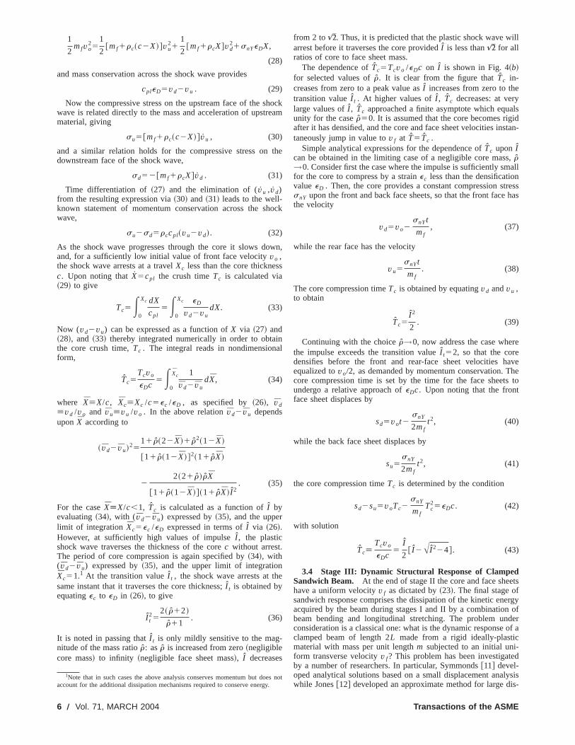
Fig. 5 Analysis of stage III of the blast response. „a… Velocity profile in phase I, „b… a free-bodydiagram of the half-beam in phase I, with the deflected shape sketched approximately, „c…velocity profile in phase II, and „d… a free-body diagram of the half-beam in phase II, with thedeflected shape sketched approximately. The accelerations of the beam are shown in „d….
u
g
i
l
e
-
f
b
e
it
entsheace-
thatbe
tionmall
l
nd-
fatndsveralf
as
s of
theing
placements using an energy balance method. These methodsummarized in Jones@13#. Here we present an approximate soltion that is valid in both the small and large displacement regimit reduces to the exact small displacement solution of Symmo@11# for small v f and is nearly equal to the approximate lardeflection solution of Jones@13# for largev f .
Active plastic straining in the beam is by a combinationplastic bending and longitudinal stretching with shear yieldneglected: An evaluation of the magnitude of the transient shforce within the face sheet in the dynamic clamped beam calation of Jones@13# reveals that shear yielding is expected only funrealistic blast pressures as discussed above. We assumyield of an beam element is described by the resultant longitudforce N and the bending momentM . The shape of the yield surface in (N,M ) space for a sandwich beam depends on the shof the cross section and the relative strength and thickness ofaces and the core. A yield locus described by
uM uMo
1uNuNo
51, (44)
whereNo andMo are the plastic values of the longitudinal forcand bending moment, respectively, is highly accurate for a sawich beam with thin, strong faces and a thick, weak core. Itcomes less accurate as the beam section approached the mlithic limit. It is difficult to obtain a simple closed-form analyticasolution for the dynamic beam response with this choice of yisurface. Here, we approximate this yield locus to be a circuscribing square such that
uNu5No (45a)
uM u5Mo , (45b)
with yield achieved when one or both of these relations are safied. We could equally well approximate the yield locus to beinscribing square such that
uNu50.5No (46a)
uM u50.5Mo , (46b)
with again at yield one or both of these relations satisfied. Jo@13# has explored the choice of circumscribing and inscribyield surfaces for a monolithic beam and shown that the resulsolutions bound the exact response. We proceed to developanalysis for the circumscribing yield locus: the corresponding fmulas for the inscribed locus may be obtained by replacingMo by0.5Mo andNo by 0.5No .
ied Mechanics
s are-e:
ndse
ofngearcu-or
thatinal
apethe
end-e-ono-
lldm-
tis-an
nesngingthe
or-
In the dynamic analysis we shall assume that displacemoccur only in a direction transverse to the original axis of tbeam and thus stretching is a result of only transverse displments. Moderate transverse deflections are considered, suchthe deflectionw at the mid-span of the beam is assumed tosmall compared to the beam length 2L and the longitudinal forceN5No can be assumed to be constant along the beam. The moof the beam can be separated into two phases as in the sdisplacement analysis of Symmonds@11#. In phase I, the centraportion of the beam translates at the initial velocityv f while seg-ments of lengthj at each end rotate about the supports. The being moment is taken to vary from2Mo at the outer stationaryplastic hinges at the supports to1Mo at ends of the segments olength j with the bending moment constant in the central flportion. Thus, time increments in curvature occur only at the eof the rotating segments while axial straining is distributed othe length of the rotating segments. A free-body diagram for hof the clamped beam is shown in Fig. 5~b!; conservation of themoment of momentum about a fixed end after a timet gives
~mLv f !L
25m~L2j!v f S j1
L2j
2 D12Mot11
2Nov f t
2
1E0
j mv fx2
jdx, (47)
where x is the axial coordinate from one end of the beam,shown in Fig. 5~b!. This equation givesj as a function of timet
j5A3t~v fNot14Mo!
mv f. (48)
Phase I continues until the traveling hinges at the inner endthe segments of lengthj coalesce at the midspan, i.e.,j5L. Thus,from ~48!, phase I ends at a timeT1
T15Mo
Nov fFA41
mL2v f2No
3Mo2 22G , (49)
and the displacement of the mid-spanw1 at this time is given by
w15v fT15Mo
NoFA41
mL2v f2No
3Mo2 22G . (50)
In phase II of the motion, stationary plastic hinges exist atmidspan and at the ends of the beam, with the moment varybetween2Mo at the beam end to1Mo at the midspan. The
MARCH 2004, Vol. 71 Õ 7
d
a
rt
e
s
r
the
e
aceionhesion
itsi-edte ofeamges.p-
ndi-ut
re-the
e
nce-
velocity profile is triangular, as sketched in Fig. 5~c!. The equationof motion of the half-beam in phase II follows from the free-bodiagram sketched in Fig. 5~d! as
2Mo1Now52w
L E0
L
mx2dx52mL2
3w, (51)
where x is the axial coordinate from one end of the beamshown in Fig. 5~d!. With initial conditions w(T1)5w1 andw(T1)5v f , this differential equation admits a solution of thform
w~ t !5v f
vsin@v~ t2T1!#1S 2Mo
No1w1D cos@v~ t2T1!#2
2Mo
No,
(52a)
where
v51
LA3No
m. (52b)
The maximum deflectionw of the midspan of the beam occursa timeT when w(T)50. Upon substituting this termination condition in the velocity equation, as given by the time derivative~52a!, the response timeT is obtained as
T5T111
vtan21F Nov f
v~2Mo1w1No!G , (53)
and the corresponding maximum deflection of the midspan ofbeam is
w5Av f2
v2 1S 2Mo
No1w1D 2
22Mo
No. (54)
The deflected shape of the beam can be obtained using the pdure detailed on p. 81 of Jones@13# but the derivation and resulare omitted here as they are not central to the present discus
We specialize this analysis to the case of sandwich beams.call that we are considering clamped sandwich beams of spanLwith identical face sheets of thicknessh and a core of thicknessc,as shown in Fig. 1. The face sheets are made from a rigid ideplastic material of yield strengths f Y and densityr f , while thecore of densityrc has a normal compressive strengthsnY and alongitudinal strengths lY . The plastic bending moment of thsandwich beam with the compressed core is given by
Mo5s lY
~12ec!c2
41s f Yh@~12ec!c1h#, (55)
while the plastic membrane forceNo is given by
No52s f Yh1s lYc. (56)
For simplicity we assume that the plastic membrane forceNodue to the core is unaffected by the degree of core compreswhile this assumption is thought to be reasonable for all the coconsidered, it requires experimental verification. We now intduce the nondimensional geometric variables of the sandwbeam
c[c
L, h[
h
c, c[ c~12ec!, and h[
h
12ec, (57)
and the nondimensional core properties
r[rc
r f, s l[
s lY
s f Yand sn[
snY
s f Y. (58)
The nondimensional structural response timeT and blast impulseI are
T[T
LAs f Y
r f, I [
I
LAr fs f Y
[I cAsneDh
z, (59)
8 Õ Vol. 71, MARCH 2004
y
as
e
t-of
the
oce-
sion.Re-2
ally
ion;reso-ich
wherezI is the blast impulse transmitted to the structure byfluid. Consequently, the response timeT, as given by~53!, can berewritten in the nondimensional form as
T5a2
2
c~2h1 r !
I zFA11
4 I 2z2a3
3a1a2
21G1A c~2h1 r !
3c~2h1s l c/ c!tan21F4 I zA a3
3a1a214 I 2z2a3G ,
(60)
where
a15 c3@~112h!2211s l c/ c#~112h!c~ r12h!, (61a)
a25c@~112h!2211s l c/ c#
2h1s l c/ c, and (61b)
a35 c~112h!. (61c)
The maximum defection~54! of the inner and outer faces at thmidspan can be written nondimensionally as
w[w
L5
a2
2FA11
8 I 2z2a3
3a1a221G , (62a)
and
wo5w1ecc, (62b)
respectively. It is emphasized that the deflection of the inner fof the sandwich beam is due to only stage III of the deformathistory, while the deflection of the outer face is the sum of tdeflections in stage III and the deflection due to core compresin stage II.
It is difficult to give a precise failure criterion for the beam asis anticipated that the blast impulse for incipient failure is sentive to the details of the built-in end conditions of the clampbeams. Here, we state a failure criterion based on an estimathe tensile strain in the face sheets due to stretching of the band neglect the tensile strains due to bending at the plastic hinThe tensile strainem in the face sheets due to stretching is aproximately equal to
em51
2 S w
L D 2
. (63)
By setting this strainem to equal the tensile ductilitye f of the facesheet material, an expression is obtained for the maximum nomensional impulseI c that the sandwich beam can sustain withotensile failure of the face sheets; substitution of~63! into ~62a!,with the choiceem5e f , gives
I c51
zA3a1a2
8a3F S 2A2e f
a2
11D 2
21G . (64)
The above analysis, comprising stages I, II, and III for thesponse of a clamped sandwich beam to blast loading, givesdeflectionw, response timeT, the core compressionec and themaximum tensile strainem in the sandwich beam in terms of
i. the loading parameters as specified by the blast impulsI ,and the fluid-structure interaction parameterc,
ii. the beam geometryc and h, andiii. the core properties as given by the core relative densityr,
its longitudinal tensile strengths l , compressive strengthsnand its densification straineD .
We proceed to illustrate graphically the functional dependeof w, T, ec , andem on the blast impulseI . Consider a represen
Transactions of the ASME
a
a
zn
a
r
thecor-wichcorewo
lasttry
w-eenim-
ntlast.
he
of a
xi-
m-
of
thicngth
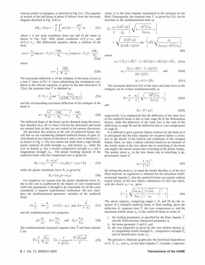
tative sandwich beam withc5h50.1 and comprising a pyramidacore of relative densityr50.1 made from the same solid materias the face sheets~with eY50.2%). As specified in Section II, thecore yields rather than elastically buckles, and the normallongitudinal strengths of this pyramidal core aresn50.05 ands l50, respectively. The densification strain of the core is takeneD50.5. To complete the specification, we assume a flustructure interaction parameterc51.79 which is representative oan underwater blast with a time constantu50.1 ms and 10 mmthick steel faces as discussed in Section III A. The normalideflectionw of the inner face of the sandwich beam and respotime T are plotted in Fig. 6~a! as a function of the normalizedblast impulse while the compressionec and tensile stretchem areplotted in Fig. 6~b!. For I ,0.03, the compressive strainec in-duced in the core in Stage II is less thaneD and w increasesapproximately quadratically withI . At higher impulses the corecompression is fixed at the densification limiteD and w scalesapproximately linearly withI . On the other hand, the structurresponse time initially increases linearly withI , but at high im-pulses the beam behaves as a stretched plastic string andT isalmost independent of the magnitude ofI .
4 Performance Charts for Water Blast ResistanceThe analysis detailed above is now used to investigate the
tive response of monolithic and sandwich beams to blast load
Fig. 6 Response of a clamped sandwich beam „ cÄ0.1,hÄ0.1… with a pyramidal core „rÄ0.1,eYÄ0.002,eDÄ0.5… for anassumed cÄ1.78; „a… the normalized response time T and de-flection w and „b… core compression ec , and tensile strain inbeam em , as a function of the normalized blast impulse I
Journal of Applied Mechanics
ll
nd
asid-f
edse
l
ela-ing.
In a typical design scenario, the solid material and length ofstructural element are dictated by design constraints such asrosion resistance and bulkhead spacing, thus leaving the sandpanel geometry, viz. the face sheet and core thickness, andrelative density and topology, as the free design variables. Tdesign problems will be addressed:
1. For a given material combination, beam length and bimpulse, what is the relation between sandwich geomeand the inner face sheet deflection?
2. For a given material combination, beam length and alloable inner face sheet deflection, what is the relation betwthe required sandwich geometry and the level of blastpulse?
4.1 Monolithic Beams. As a reference case we first presethe response of a monolithic beam subjected to a water bConsider a monolithic beam of thicknessh and length 2L madefrom a rigid-ideally plastic solid material of densityr f and yieldstrengths f Y subjected to a blast impulseI .
We define a fluid-structure interaction parameterc
c5ch
L5
rwcwu
r fL, (65)
which is closely related to the Taylor@1# fluid-structure interactionparameterc but written in terms of the specified beam length. Timpulse I trans transmitted to the beam is given by~20b! for aspecified value ofc and a known beam geometryh/L.
First, we specialize the analysis of Section 3.4 to the casemonolithic beam with plastic momentMo5Noh/4, where No5hs f Y is the plastic membrane force. The nondimensional mamum deflection of the midspan of the beamw5w/L and normal-ized structural response timeT[T/LAr f /s fY follow from ~54!and ~53!, respectively, as
w5h
2LFA11
8 I 2z2
3 S L
hD 4
21G and (66a)
T51
2 I zS h
LD 2FA11
4
3I 2z2S L
hD 4
21G1
1
)tan21F 2 I z~L/h!2
A314 I 2z2~L/h!4G , (66b)
where zI is the impulse transmitted into the structure. Forz I!1, the above relations reduce to
w52
3I 2z2S L
hD 3
(67)
T5 I zS L
hD 2
, (68)
which are identical to the small deflection predictions of Symonds@11#.
With the tensile strain in the beam given by~63!, the maximumimpulseI c sustained by a monolithic beam made from materialtensile ductilitye f is
I c51
zA3
8 S h
L D 2F S 2A2e f S L
hD11D 2
21G . (69)
A representative design chart is now constructed for a monolibeam subjected to a water blast. Consider a steel beam of le2L510 m subjected to a blast with a decay timeu50.12 ms. The
MARCH 2004, Vol. 71 Õ 9
g-t
t
a
t
h
n
h
e
ra--
el
lastuml
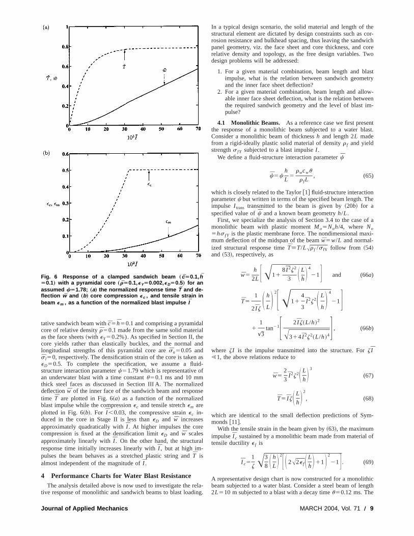
fluid-structure interaction parameterc then takes the valuec5531023. Contours of nondimensional deflectionw are plotted inFig. 7 as a function of the normalized blast impulseI and beamgeometry,h/L, for c5531023. Note that the contours of thewhave been truncated at high impulses due to tensile tearindictated by~69!, with the choicee f50.2. Contours of nondimensional massM5M /(L2r f)52h/L, whereM is the mass per uniwidth of the beam, have also been added to the figure. Aspected, the beam deflection increases increasing with blastpulse, for a beam of given mass.
4.2 Sandwich Beams. The blast response of clamped sanwich beams, comprising solid faces and the five types of codiscussed in Section 2, will be analyzed in this section. We resattention to cores made from the same solid material as the sface sheets in order to reduce the number of independent nomensional groups by one. With the sandwich beam lengthmaterial combination specified, the design variables in the prlem are the nondimensional core thicknessc[c/L and face sheethicknessh[h/c.
Figure 8 shows a design chart with axesc andh for a clampedsandwich beam with a pyramidal core (r50.1, eY50.002) andsubjected to a normalized blast impulseI 51022. The fluid-structure interaction parameter is again taken asc5531023; thisis representative for steel sandwich beams of length 2L510 msubject to a water blast with a decay constantu50.12 ms. Further,the densification straineD of the core is assumed to be 0.5 and ttensile ductility of the solid steel is taken ase f50.2. Contours ofnondimensional maximum deflection of the mid-span of the inface of the beam and contours of the compressive strainec in thecore have been added to the chart: bothw and ec increase withdecreasingc and beam failure by tensile tearing of the face sheis evident at the top left-hand corner of the chart.
The effect of the fluid-structure interaction parameterc uponthe likelihood of tensile failure of the above sandwich beamshown in Fig. 9. The figure shows the regime of tensile failurethe face sheets on a design chart with axes (c,h). Apart from thechoice ofc, the nondimensional parameters are the same as tused to construct Fig. 8:r50.1 andeD50.5 for the pyramidalcore,e f50.2 for the faces andI 51022. With increasing values of
Fig. 7 Design chart for a monolithic beam of tensile ductilitye fÄ0.2, subjected to a water blast with cÄ5Ã10À3. Contoursof the midspan displacement w are given as solid lines andcontours of dimensionless mass M are shown as dotted lines.
10 Õ Vol. 71, MARCH 2004
as
ex-im-
d-resrictolidndi-nd
ob-
e
er
ets
isof
ose
c ~associated with shorter spans, 2L, and with longer values ofthe decay constantu!, tensile failure is less likely. Thus, tensilfailure is unlikely to occur for sandwich beams providedc ex-ceeds approximately 0.02.
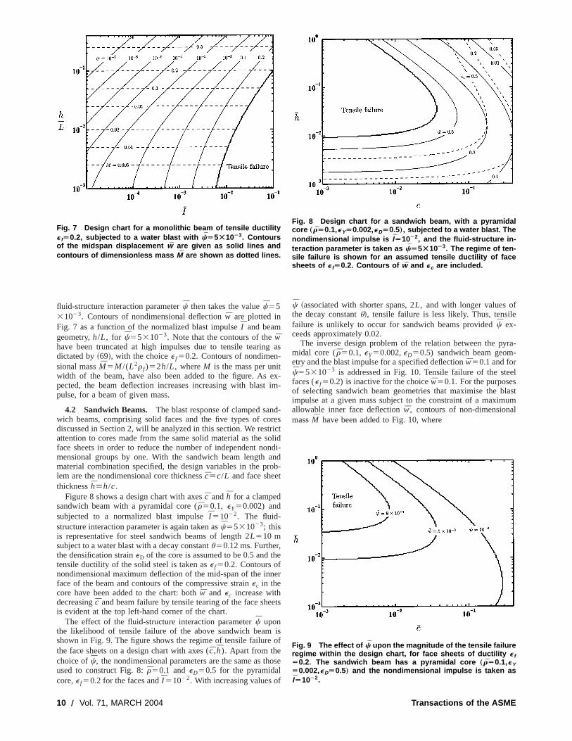
The inverse design problem of the relation between the pymidal core (r50.1, eY50.002,eD50.5) sandwich beam geometry and the blast impulse for a specified deflectionw50.1 and forc5531023 is addressed in Fig. 10. Tensile failure of the stefaces (e f50.2) is inactive for the choicew50.1. For the purposesof selecting sandwich beam geometries that maximise the bimpulse at a given mass subject to the constraint of a maximallowable inner face deflectionw, contours of non-dimensionamassM have been added to Fig. 10, where
Fig. 8 Design chart for a sandwich beam, with a pyramidalcore „rÄ0.1,eYÄ0.002,eDÄ0.5…, subjected to a water blast. Thenondimensional impulse is IÄ10À2, and the fluid-structure in-teraction parameter is taken as cÄ5Ã10À3. The regime of ten-sile failure is shown for an assumed tensile ductility of facesheets of e fÄ0.2. Contours of w and ec are included.
Fig. 9 The effect of c upon the magnitude of the tensile failureregime within the design chart, for face sheets of ductility e fÄ0.2. The sandwich beam has a pyramidal core „rÄ0.1,eYÄ0.002,eDÄ0.5… and the nondimensional impulse is taken asIÄ10À2.
Transactions of the ASME
i-
lo
o
a
ia
ur
na
t
hw
a
de-r, theains
ichhtly:byn to
s atos-
end
hileingerior
ich
hen
heout
The
M5M
r fL2 52~2hc1 cr !, (70)
and M is the mass per unit width of the sandwich beam. Tfigure reveals that geometries that maximize the blast impulsIfor a given massM haveh→0 at almost constantc, implying thath/L→0. The physical interpretation is as follows. With decreasface sheet thickness~or face sheet mass! the blast impulse transmitted to the structure reduces: The Taylor analysis givesI trans→0 ash→0. This limit is practically unrealistic as a minimumface sheet thickness is required for other reasons, for exampwithstand wave loading, quasi-static indentation by foreignjects such as rocks and other vessels and fragment captureblast event. Consequently, we add the additional constraintminimum normalized face sheet thicknessh/L into the analysis.Contours ofh/L for two selected values ofh/L have been addedto Fig. 10. These lines represent limits on acceptable sandwbeam designs, with designs lying above these lines satisfyingconstraint onh/L: designs that maximize blast impulse forgiven mass then lie along the lines of constanth/L.
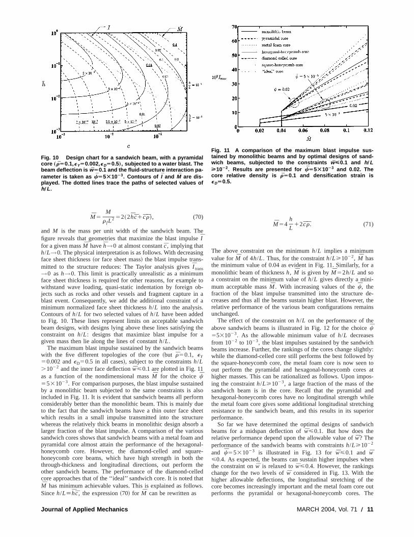
The maximum blast impulse sustained by the sandwich bewith the five different topologies of the core~but r50.1, eY50.002 andeD50.5 in all cases!, subject to the constraintsh/L.1022 and the inner face deflectionw<0.1 are plotted in Fig. 11as a function of the nondimensional massM for the choicec5531023. For comparison purposes, the blast impulse sustaby a monolithic beam subjected to the same constraints isincluded in Fig. 11. It is evident that sandwich beams all perfoconsiderably better than the monolithic beam. This is mainly dto the fact that the sandwich beams have a thin outer face swhich results in a small impulse transmitted into the structwhereas the relatively thick beams in monolithic design absolarger fraction of the blast impulse. A comparison of the variosandwich cores shows that sandwich beams with a metal foampyramidal core almost attain the performance of the hexagohoneycomb core. However, the diamond-celled and squhoneycomb core beams, which have high strength in boththrough-thickness and longitudinal directions, out performother sandwich beams. The performance of the diamond-cecore approaches that of the ‘‘ideal’’ sandwich core. It is noted tM has minimum achievable values. This is explained as folloSinceh/L[hc, the expression~70! for M can be rewritten as
Fig. 10 Design chart for a sandwich beam, with a pyramidalcore „rÄ0.1,eYÄ0.002,eDÄ0.5…, subjected to a water blast. Thebeam deflection is wÄ0.1 and the fluid-structure interaction pa-rameter is taken as cÄ5Ã10À3. Contours of I and M are dis-played. The dotted lines trace the paths of selected values ofh ÕL .
Journal of Applied Mechanics
hee
ng
e tob-in af a
ichthea
ms
nedlso
rmueheetreb ausandal-re-thehelledats.
M54h
L12cr. (71)
The above constraint on the minimumh/L implies a minimumvalue forM of 4h/L. Thus, for the constrainth/L>1022, M hasthe minimum value of 0.04 as evident in Fig. 11. Similarly, formonolithic beam of thicknessh, M is given byM52h/L and soa constraint on the minimum value ofh/L gives directly a mini-mum acceptable massM . With increasing values of thec, thefraction of the blast impulse transmitted into the structurecreases and thus all the beams sustain higher blast. Howeverelative performance of the various beam configurations remunchanged.
The effect of the constraint onh/L on the performance of theabove sandwich beams is illustrated in Fig. 12 for the choicec5531023. As the allowable minimum value ofh/L decreasesfrom 1022 to 1023, the blast impulses sustained by the sandwbeams increase. Further, the rankings of the cores change sligwhile the diamond-celled core still performs the best followedthe square-honeycomb core, the metal foam core is now seeout perform the pyramidal and hexagonal-honeycomb corehigher masses. This can be rationalized as follows. Upon imping the constrainth/L>1023, a large fraction of the mass of thsandwich beam is in the core. Recall that the pyramidal ahexagonal-honeycomb cores have no longitudinal strength wthe metal foam core gives some additional longitudinal stretchresistance to the sandwich beam, and this results in its supperformance.
So far we have determined the optimal designs of sandwbeams for a midspan deflection ofw<0.1. But how does therelative performance depend upon the allowable value ofw? Theperformance of the sandwich beams with constraintsh/L>1022
and c5531023 is illustrated in Fig. 13 forw<0.1 and w<0.4. As expected, the beams can sustain higher impulses wthe constraint onw is relaxed tow<0.4. However, the rankingschange for the two levels ofw considered in Fig. 13. With thehigher allowable deflections, the longitudinal stretching of tcore becomes increasingly important and the metal foam coreperforms the pyramidal or hexagonal-honeycomb cores.
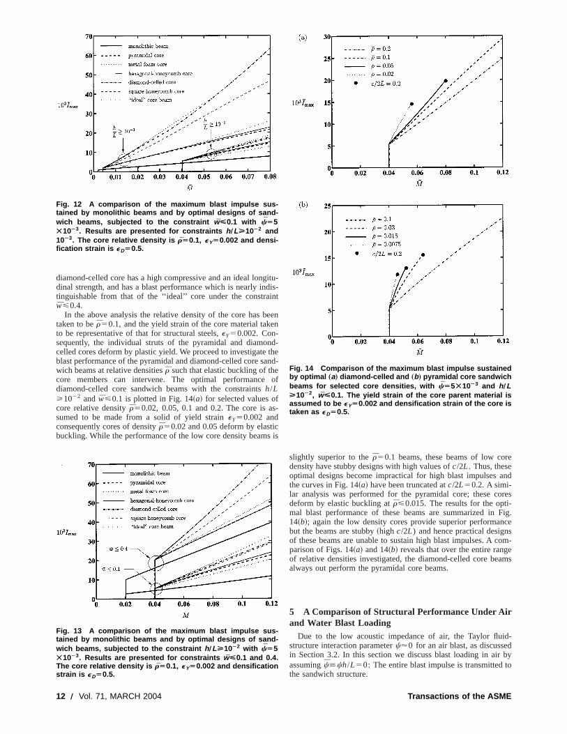
Fig. 11 A comparison of the maximum blast impulse sus-tained by monolithic beams and by optimal designs of sand-wich beams, subjected to the constraints wÏ0.1 and h ÕLÐ10À2. Results are presented for cÄ5Ã10À3 and 0.02. Thecore relative density is rÄ0.1 and densification strain iseDÄ0.5.
MARCH 2004, Vol. 71 Õ 11
g
i
e
n
a
f
cs
re
and
res-Fig.ce
som-eams
d-dby
to
diamond-celled core has a high compressive and an ideal londinal strength, and has a blast performance which is nearly intinguishable from that of the ‘‘ideal’’ core under the constraw<0.4.
In the above analysis the relative density of the core has btaken to ber50.1, and the yield strain of the core material takto be representative of that for structural steels,eY50.002. Con-sequently, the individual struts of the pyramidal and diamocelled cores deform by plastic yield. We proceed to investigateblast performance of the pyramidal and diamond-celled core swich beams at relative densitiesr such that elastic buckling of thecore members can intervene. The optimal performancediamond-celled core sandwich beams with the constraintsh/L>1022 andw<0.1 is plotted in Fig. 14~a! for selected values ocore relative densityr50.02, 0.05, 0.1 and 0.2. The core is asumed to be made from a solid of yield straineY50.002 andconsequently cores of densityr50.02 and 0.05 deform by elastibuckling. While the performance of the low core density beam
Fig. 12 A comparison of the maximum blast impulse sus-tained by monolithic beams and by optimal designs of sand-wich beams, subjected to the constraint wÏ0.1 with cÄ5Ã10À3. Results are presented for constraints h ÕLÐ10À2 and10À3. The core relative density is rÄ0.1, eYÄ0.002 and densi-fication strain is eDÄ0.5.
Fig. 13 A comparison of the maximum blast impulse sus-tained by monolithic beams and by optimal designs of sand-wich beams, subjected to the constraint h ÕLÐ10À2 with cÄ5Ã10À3. Results are presented for constraints wÏ0.1 and 0.4.The core relative density is rÄ0.1, eYÄ0.002 and densificationstrain is eDÄ0.5.
12 Õ Vol. 71, MARCH 2004
itu-dis-nt
eenn
d-thend-
of
s-
is
slightly superior to ther50.1 beams, these beams of low codensity have stubby designs with high values ofc/2L. Thus, theseoptimal designs become impractical for high blast impulsesthe curves in Fig. 14~a! have been truncated atc/2L50.2. A simi-lar analysis was performed for the pyramidal core; these codeform by elastic buckling atr<0.015. The results for the optimal blast performance of these beams are summarized in14~b!; again the low density cores provide superior performanbut the beams are stubby~high c/2L) and hence practical designof these beams are unable to sustain high blast impulses. A cparison of Figs. 14~a! and 14~b! reveals that over the entire rangof relative densities investigated, the diamond-celled core bealways out perform the pyramidal core beams.
5 A Comparison of Structural Performance Under Airand Water Blast Loading
Due to the low acoustic impedance of air, the Taylor fluistructure interaction parameterc'0 for an air blast, as discussein Section 3.2. In this section we discuss blast loading in airassumingc[ch/L50: The entire blast impulse is transmittedthe sandwich structure.
Fig. 14 Comparison of the maximum blast impulse sustainedby optimal „a… diamond-celled and „b… pyramidal core sandwichbeams for selected core densities, with cÄ5Ã10À3 and h ÕLÐ10À2, wÏ0.1. The yield strain of the core parent material isassumed to be eYÄ0.002 and densification strain of the core istaken as eDÄ0.5.
Transactions of the ASME
ir
m
c
re
fors is
incanum
s is
on-
gainhicains
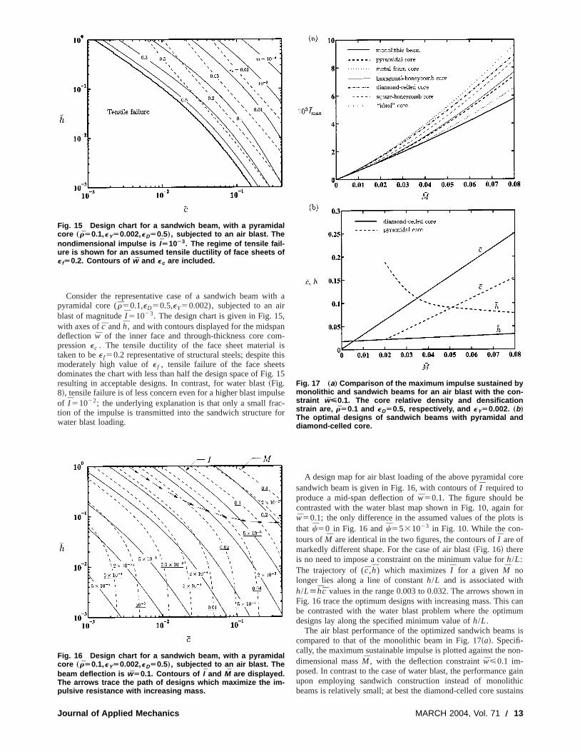
Consider the representative case of a sandwich beam wpyramidal core (r50.1,eD50.5,eY50.002), subjected to an aiblast of magnitudeI 51023. The design chart is given in Fig. 15with axes ofc andh, and with contours displayed for the midspadeflectionw of the inner face and through-thickness core copressionec . The tensile ductility of the face sheet materialtaken to bee f50.2 representative of structural steels; despite tmoderately high value ofe f , tensile failure of the face sheetdominates the chart with less than half the design space of Figresulting in acceptable designs. In contrast, for water blast~Fig.8!, tensile failure is of less concern even for a higher blast impuof I 51022; the underlying explanation is that only a small fration of the impulse is transmitted into the sandwich structurewater blast loading.
Fig. 15 Design chart for a sandwich beam, with a pyramidalcore „rÄ0.1,eYÄ0.002,eDÄ0.5…, subjected to an air blast. Thenondimensional impulse is IÄ10À3. The regime of tensile fail-ure is shown for an assumed tensile ductility of face sheets ofe fÄ0.2. Contours of w and ec are included.
Fig. 16 Design chart for a sandwich beam, with a pyramidalcore „rÄ0.1,eYÄ0.002,eDÄ0.5…, subjected to an air blast. Thebeam deflection is wÄ0.1. Contours of I and M are displayed.The arrows trace the path of designs which maximize the im-pulsive resistance with increasing mass.
Journal of Applied Mechanics
th a
,n-
ishiss. 15
lse-
for
A design map for air blast loading of the above pyramidal cosandwich beam is given in Fig. 16, with contours ofI required toproduce a mid-span deflection ofw50.1. The figure should becontrasted with the water blast map shown in Fig. 10, againw50.1; the only difference in the assumed values of the plotthat c50 in Fig. 16 andc5531023 in Fig. 10. While the con-tours ofM are identical in the two figures, the contours ofI are ofmarkedly different shape. For the case of air blast~Fig. 16! thereis no need to impose a constraint on the minimum value forh/L:The trajectory of (c,h) which maximizesI for a given M nolonger lies along a line of constanth/L and is associated withh/L[hc values in the range 0.003 to 0.032. The arrows shownFig. 16 trace the optimum designs with increasing mass. Thisbe contrasted with the water blast problem where the optimdesigns lay along the specified minimum value ofh/L.
The air blast performance of the optimized sandwich beamcompared to that of the monolithic beam in Fig. 17~a!. Specifi-cally, the maximum sustainable impulse is plotted against the ndimensional massM , with the deflection constraintw<0.1 im-posed. In contrast to the case of water blast, the performanceupon employing sandwich construction instead of monolitbeams is relatively small; at best the diamond-celled core sust
Fig. 17 „a… Comparison of the maximum impulse sustained bymonolithic and sandwich beams for an air blast with the con-straint wÏ0.1. The core relative density and densificationstrain are, rÄ0.1 and eDÄ0.5, respectively, and eYÄ0.002. „b…The optimal designs of sandwich beams with pyramidal anddiamond-celled core.
MARCH 2004, Vol. 71 Õ 13
t
f
nh
hlerit
i
na
h
ti
t
s
ore
ifi-
es
ces are
thethesonhatn
an impulse about 45% greater than a monolithic beam of eqmass. The geometry of the optimal pyramidal and diamond-cesandwich core beams of Fig. 17~a! are plotted in Fig. 17~b!. Forboth configurations,c increases with increasing mass, with thoptimal pyramidal core beams having a lowerc ~and a higherh)as compared to the optimal diamond-celled core beams.
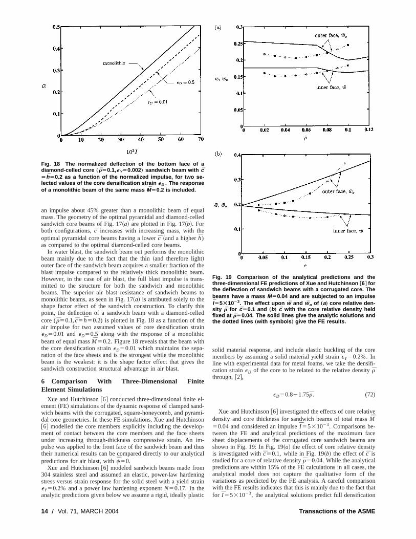
In water blast, the sandwich beam out performs the monolibeam mainly due to the fact that the thin~and therefore light!outer face of the sandwich beam acquires a smaller fraction oblast impulse compared to the relatively thick monolithic beaHowever, in the case of air blast, the full blast impulse is tramitted to the structure for both the sandwich and monolitbeams. The superior air blast resistance of sandwich beammonolithic beams, as seen in Fig. 17~a! is attributed solely to theshape factor effect of the sandwich construction. To clarify tpoint, the deflection of a sandwich beam with a diamond-cecore (r50.1,c5h50.2) is plotted in Fig. 18 as a function of thair impulse for two assumed values of core densification steD50.01 andeD50.5 along with the response of a monolithbeam of equal massM50.2. Figure 18 reveals that the beam withe core densification straineD50.01 which maintains the separation of the face sheets and is the strongest while the monolbeam is the weakest: it is the shape factor effect that givessandwich construction structural advantage in air blast.
6 Comparison With Three-Dimensional FiniteElement Simulations
Xue and Hutchinson@6# conducted three-dimensional finite eement~FE! simulations of the dynamic response of clamped sawich beams with the corrugated, square-honeycomb, and pyrdal core geometries. In these FE simulations, Xue and Hutchin@6# modelled the core members explicitly including the develoment of contact between the core members and the face sunder increasing through-thickness compressive strain. Anpulse was applied to the front face of the sandwich beam andtheir numerical results can be compared directly to our analytpredictions for air blast, withc50.
Xue and Hutchinson@6# modeled sandwich beams made fro304 stainless steel and assumed an elastic, power-law hardestress versus strain response for the solid steel with a yield seY50.2% and a power law hardening exponentN50.17. In theanalytic predictions given below we assume a rigid, ideally pla
Fig. 18 The normalized deflection of the bottom face of adiamond-celled core „rÄ0.1,eYÄ0.002… sandwich beam with cÄhÄ0.2 as a function of the normalized impulse, for two se-lected values of the core densification strain eD . The responseof a monolithic beam of the same mass MÄ0.2 is included.
14 Õ Vol. 71, MARCH 2004
uallled
e
hic
them.s-ics to
isled
ainch-thicthe
l-d-mi-sonp-eetsim-huscal
mningrain
tic
solid material response, and include elastic buckling of the cmembers by assuming a solid material yield straineY50.2%. Inline with experimental data for metal foams, we take the denscation straineD of the core to be related to the relative densityrthrough,@2#,
eD50.821.75r. (72)
Xue and Hutchinson@6# investigated the effects of core relativdensity and core thickness for sandwich beams of total masM50.04 and considered an impulseI 5531023. Comparisons be-tween the FE and analytical predictions of the maximum fasheet displacements of the corrugated core sandwich beamshown in Fig. 19: In Fig. 19~a! the effect of core relative densityis investigated withc50.1, while in Fig. 19~b! the effect ofc isstudied for a core of relative densityr50.04. While the analyticalpredictions are within 15% of the FE calculations in all cases,analytical model does not capture the qualitative form ofvariations as predicted by the FE analysis. A careful compariwith the FE results indicates that this is mainly due to the fact tfor I 5531023, the analytical solutions predict full densificatio
Fig. 19 Comparison of the analytical predictions and thethree-dimensional FE predictions of Xue and Hutchinson †6‡ forthe deflection of sandwich beams with a corrugated core. Thebeams have a mass MÄ0.04 and are subjected to an impulseIÄ5Ã10À3. The effect upon w and w o of „a… core relative den-sity r for cÄ0.1 and „b… c with the core relative density heldfixed at rÄ0.04. The solid lines give the analytic solutions andthe dotted lines „with symbols … give the FE results.
Transactions of the ASME
t
ct
e
n
t
e
e
e
beenns.ploreake
olo-mu-y andula-Xue
bela-
atesthe
hereeetsssedpro-
theair
ratedrac-d iningare
cal-
s fort to, and byd-facetureandlithics a
ithicoreinal
onsnu-
med
orttheres.ko,or
ves
nd
ich
i-
in nearly all cases while in the FE simulations no distinct denfication limit exits; rather, continued core compression occursincreasing stress level after contact has begun between themembers and the face sheets. An improved core constitumodel with continued hardening rather than lockup after socritical straineD may be able to address this deficiency; thishowever beyond the scope of the present study.
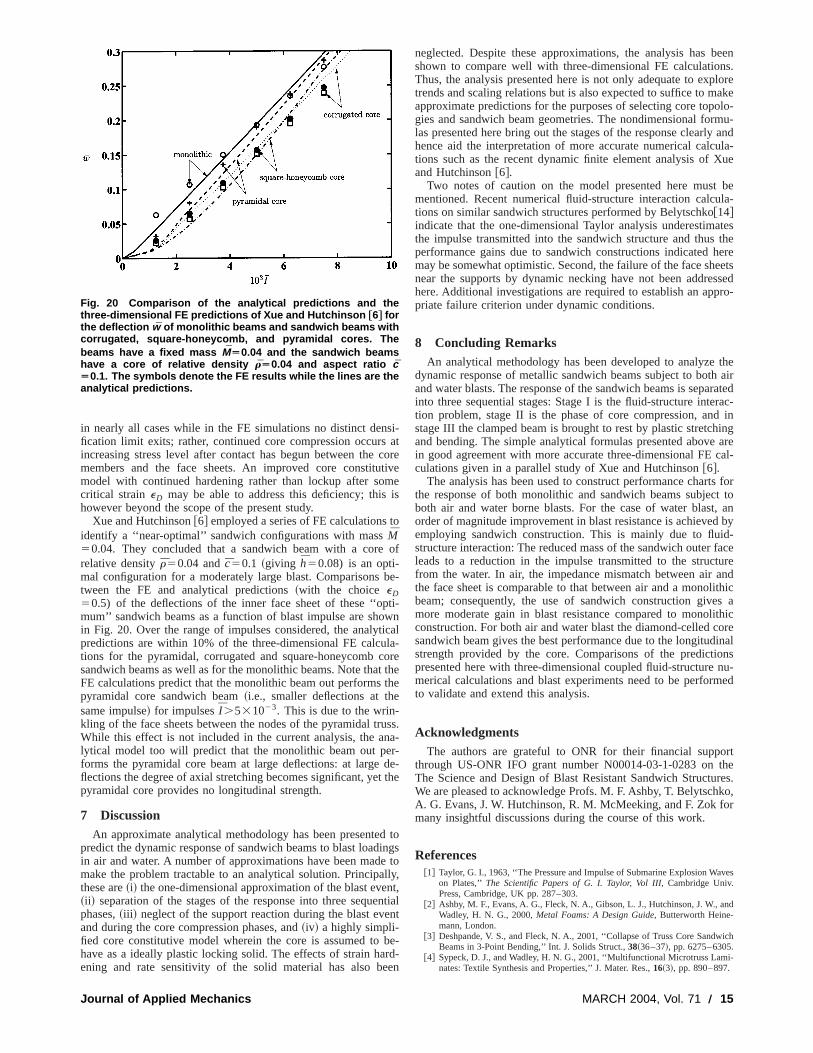
Xue and Hutchinson@6# employed a series of FE calculationsidentify a ‘‘near-optimal’’ sandwich configurations with massM50.04. They concluded that a sandwich beam with a corerelative densityr50.04 andc50.1 ~giving h50.08) is an opti-mal configuration for a moderately large blast. Comparisonstween the FE and analytical predictions~with the choiceeD50.5) of the deflections of the inner face sheet of these ‘‘opmum’’ sandwich beams as a function of blast impulse are shoin Fig. 20. Over the range of impulses considered, the analytpredictions are within 10% of the three-dimensional FE calcutions for the pyramidal, corrugated and square-honeycombsandwich beams as well as for the monolithic beams. Note thaFE calculations predict that the monolithic beam out performspyramidal core sandwich beam~i.e., smaller deflections at thsame impulse! for impulsesI .531023. This is due to the wrin-kling of the face sheets between the nodes of the pyramidal trWhile this effect is not included in the current analysis, the alytical model too will predict that the monolithic beam out peforms the pyramidal core beam at large deflections: at largeflections the degree of axial stretching becomes significant, yepyramidal core provides no longitudinal strength.
7 DiscussionAn approximate analytical methodology has been presente
predict the dynamic response of sandwich beams to blast loadin air and water. A number of approximations have been madmake the problem tractable to an analytical solution. Principathese are~i! the one-dimensional approximation of the blast eve~ii ! separation of the stages of the response into three sequephases,~iii ! neglect of the support reaction during the blast evand during the core compression phases, and~iv! a highly simpli-fied core constitutive model wherein the core is assumed tohave as a ideally plastic locking solid. The effects of strain haening and rate sensitivity of the solid material has also b
Fig. 20 Comparison of the analytical predictions and thethree-dimensional FE predictions of Xue and Hutchinson †6‡ forthe deflection w of monolithic beams and sandwich beams withcorrugated, square-honeycomb, and pyramidal cores. Thebeams have a fixed mass MÄ0.04 and the sandwich beamshave a core of relative density rÄ0.04 and aspect ratio cÄ0.1. The symbols denote the FE results while the lines are theanalytical predictions.
Journal of Applied Mechanics
si-at
coretivemeis
o
of
be-
ti-wnicalla-orethe
the
uss.a-
r-de-the
d toings
tolly,nt,ntialnt
be-rd-en
neglected. Despite these approximations, the analysis hasshown to compare well with three-dimensional FE calculatioThus, the analysis presented here is not only adequate to extrends and scaling relations but is also expected to suffice to mapproximate predictions for the purposes of selecting core topgies and sandwich beam geometries. The nondimensional forlas presented here bring out the stages of the response clearlhence aid the interpretation of more accurate numerical calctions such as the recent dynamic finite element analysis ofand Hutchinson@6#.
Two notes of caution on the model presented here mustmentioned. Recent numerical fluid-structure interaction calcutions on similar sandwich structures performed by Belytschko@14#indicate that the one-dimensional Taylor analysis underestimthe impulse transmitted into the sandwich structure and thusperformance gains due to sandwich constructions indicatedmay be somewhat optimistic. Second, the failure of the face shnear the supports by dynamic necking have not been addrehere. Additional investigations are required to establish an appriate failure criterion under dynamic conditions.
8 Concluding RemarksAn analytical methodology has been developed to analyze
dynamic response of metallic sandwich beams subject to bothand water blasts. The response of the sandwich beams is sepainto three sequential stages: Stage I is the fluid-structure intetion problem, stage II is the phase of core compression, anstage III the clamped beam is brought to rest by plastic stretchand bending. The simple analytical formulas presented abovein good agreement with more accurate three-dimensional FEculations given in a parallel study of Xue and Hutchinson@6#.
The analysis has been used to construct performance chartthe response of both monolithic and sandwich beams subjecboth air and water borne blasts. For the case of water blastorder of magnitude improvement in blast resistance is achieveemploying sandwich construction. This is mainly due to fluistructure interaction: The reduced mass of the sandwich outerleads to a reduction in the impulse transmitted to the strucfrom the water. In air, the impedance mismatch between airthe face sheet is comparable to that between air and a monobeam; consequently, the use of sandwich construction givemore moderate gain in blast resistance compared to monolconstruction. For both air and water blast the diamond-celled csandwich beam gives the best performance due to the longitudstrength provided by the core. Comparisons of the predictipresented here with three-dimensional coupled fluid-structuremerical calculations and blast experiments need to be perforto validate and extend this analysis.
AcknowledgmentsThe authors are grateful to ONR for their financial supp
through US-ONR IFO grant number N00014-03-1-0283 onThe Science and Design of Blast Resistant Sandwich StructuWe are pleased to acknowledge Profs. M. F. Ashby, T. BelytschA. G. Evans, J. W. Hutchinson, R. M. McMeeking, and F. Zok fmany insightful discussions during the course of this work.
References@1# Taylor, G. I., 1963, ‘‘The Pressure and Impulse of Submarine Explosion Wa
on Plates,’’The Scientific Papers of G. I. Taylor, Vol III, Cambridge Univ.Press, Cambridge, UK pp. 287–303.
@2# Ashby, M. F., Evans, A. G., Fleck, N. A., Gibson, L. J., Hutchinson, J. W., aWadley, H. N. G., 2000,Metal Foams: A Design Guide, Butterworth Heine-mann, London.
@3# Deshpande, V. S., and Fleck, N. A., 2001, ‘‘Collapse of Truss Core SandwBeams in 3-Point Bending,’’ Int. J. Solids Struct.,38~36–37!, pp. 6275–6305.
@4# Sypeck, D. J., and Wadley, H. N. G., 2001, ‘‘Multifunctional Microtruss Lamnates: Textile Synthesis and Properties,’’ J. Mater. Res.,16~3!, pp. 890–897.
MARCH 2004, Vol. 71 Õ 15

si
-
or
oflids,
lastlied
of
,
@5# Deshpande, V. S., and Fleck, N. A., 2003, ‘‘Energy Absorption of an Egg-BMaterial,’’ J. Mech. Phys. Solids,51~1!, p. 187.
@6# Xue, Z., and Hutchinson, J. W., 2003, ‘‘A Comparative Study of BlaResistant Metal Sandwich Plates,’’ Int. J. Impact Eng., submitted for publtion.
@7# Cole, R. H., 1948,Underwater Explosions, Princeton University Press, Princeton, NJ.
@8# Swisdak, M. M., 1978, ‘‘Explosion Effects and Properties—Part II: ExplosiEffects in Water,’’ Technical Report, Naval Surface Weapons Center, DahlgVA.
@9# Smith, P. D., and Hetherington, J. G., 1994,Blast and Ballistic Loading ofStructures, Butterworth Heinemann, London.
16 Õ Vol. 71, MARCH 2004
ox
t-ca-
nen,
@10# Qiu, X., Deshpande, V. S., and Fleck, N. A., 2003, ‘‘Finite Element Analysisthe Dynamic Response of Clamped Sandwich Beams,’’ Eur. J. Mech. A/Sosubmitted for publication.
@11# Symmonds, P. S., 1954, ‘‘Large Plastic Deformations of Beams Under BType Loading,’’Proceedings of the Second U.S. National Congress of AppMechanics, pp. 505–515.
@12# Jones, N., 1971, ‘‘A Theoretical Study of the Dynamic Plastic BehaviorBeams and Plates With Finite Deflections,’’ Int. J. Solids Struct.,7, p. 1007.
@13# Jones, N., 1989,Structural Impact, Cambridge University Press, CambridgeUK.
@14# Belytschko, T., 2003, private communication.
Transactions of the ASME


![Indentation resistance of sandwich beamsmpfs/papers/PS1999b.pdf · Indentation resistance of sandwich beams A. Petras, ... The HOSBT introduced by Frostig and Baruch [8] is used in](https://img.pdfslide.us/doc/110x75/5a7657997f8b9ad22a8d5a85/indentation-resistance-of-sandwich-mpfspapersps1999bpdfaa-indentation-resistance.jpg)