Embed Size (px)
Citation preview

International Journal of Solids and Structures 43 (2006) 2243–2259
www.elsevier.com/locate/ijsolstr
The response of clamped sandwich plates with metallicfoam cores to simulated blast loading
D.D. Radford, G.J. McShane, V.S. Deshpande, N.A. Fleck *
Department of Engineering, University of Cambridge, Trumpington Street, Cambridge CB2 1PZ, UK
Received 27 December 2004; received in revised form 1 July 2005Available online 12 September 2005
Abstract
The dynamic responses of clamped circular monolithic and sandwich plates of equal areal mass have been measuredby loading the plates at mid-span with metal foam projectiles. The sandwich plates comprise AISI 304 stainless steelface sheets and aluminium alloy metal foam cores. The resistance to shock loading is quantified by the permanent trans-verse deflection at mid-span of the plates as a function of projectile momentum. It is found that the sandwich plateshave a higher shock resistance than monolithic plates of equal mass. Further, the shock resistance of the sandwichplates increases with increasing thickness of sandwich core. Finite element simulations of these experiments are in goodagreement with the experimental measurements and demonstrate that the strain rate sensitivity of AISI 304 stainlesssteel plays a significant role in increasing the shock resistance of the monolithic and sandwich plates. Finally, the finiteelement simulations were employed to determine the pressure versus time history exerted by the foam projectiles on theplates. It was found that the pressure transient was reasonably independent of the dynamic impedance of the plate, sug-gesting that the metal foam projectile is a convenient experimental tool for ranking the shock resistance of competingstructures.� 2005 Elsevier Ltd. All rights reserved.
Keywords: Impact loading; Sandwich plates; Metallic foams; Finite elements
1. Introduction
Clamped monolithic plates are commonly used in the design of commercial and military vehicles.For example, the outermost hull of a ship comprises plates welded to an array of stiffeners. The superior
0020-7683/$ - see front matter � 2005 Elsevier Ltd. All rights reserved.doi:10.1016/j.ijsolstr.2005.07.006
* Corresponding author. Tel.: +44 1223 332650; fax: +44 1223 765046.E-mail address: [email protected] (N.A. Fleck).

2244 D.D. Radford et al. / International Journal of Solids and Structures 43 (2006) 2243–2259
performance of sandwich plates relative to monolithic solid plates is well established for applicationsrequiring high quasi-static strength. However, the resistance of sandwich plates to dynamic loads remainsto be fully investigated in order to quantify the advantages of sandwich design over monolithic design forpotential application in shock resistant structures.
Over the past fifty years, the response of monolithic beams and plates to shock type loading has beenextensively investigated. For example, Wang and Hopkins (1954) and Symmonds (1954) have analysedthe impulse response of clamped circular monolithic plates and clamped monolithic beams, respectively.Their analyses were restricted to infinitesimal strains and displacements. Jones (1968) presented an approx-imate analytical solution for the finite deflection of simply supported circular monolithic plates by directapplication of the principle of virtual work for an assumed deformation mode. More recently, Fleck andDeshpande (2004) have proposed an analytical model for the finite deflection response of clamped sandwichbeams subjected to shock loadings, including the effects of fluid–structure interaction. They have demon-strated the accuracy of their analytical model in the case of no fluid–structure interaction by direct compar-ison with the finite element calculations of Xue and Hutchinson (2004) for clamped sandwich beams. Theanalytical model of Fleck–Deshpande has been extended by Qiu et al. (2005) for clamped circular sandwichplates, and is again supported by finite element calculations of Xue and Hutchinson (2003) for sandwichplates with a foam-like core and the effects of fluid–structure interaction again neglected. These recentinvestigations have each demonstrated that circular sandwich plates can posses a superior resistance toshock loading than monolithic plates of the same areal mass.
To date, there have been little experimental data to support or refute these predictions, as it is difficult toperform laboratory scale experiments with a prescribed dynamic loading history. In the recent study byRadford et al. (2005), an experimental technique was introduced to subject structures to high intensity pres-sure pulses using metal foam projectiles. The applied pressure versus time pulse attempts to mimic shockloading in air and in water, with peak pressures on the order of 100 MPa and loading times of approxi-mately 100 ls. This experimental technique has been employed by Radford et al. (in press) and Rathbunet al. (in press) to investigate the dynamic response of clamped sandwich beams with metal foam and latticecores. These studies indicated that the sandwich beams have a superior shock resistance compared tomonolithic beams of the same mass. However, no attempt was made to de-convolute the cross-couplingbetween the dynamic response of the beams and that of the projectile, making it difficult to quantify theenhanced shock resistance of the sandwich beams.
In this study, we employ the experimental technique of Radford et al. (2005) to explore the shock resis-tance of clamped circular monolithic and aluminium foam core sandwich plates of equal mass. First, themanufacturing route of the sandwich plates is detailed and the experimental procedure is described forloading the plates at mid-span by metal foam projectiles. The experimental results are compared with finiteelement predictions. Finally, the finite element simulations are used to determine the cross-coupling be-tween the foam projectile loading and the plate response.
2. Experimental investigation
In this study, metal foam projectiles are used to load dynamically clamped circular sandwich platescomprising an aluminium metal foam core and AISI 304 stainless steel face sheets. The main aims ofthe experimental investigation are:
(i) To compare the dynamic resistance of sandwich plates with monolithic plates (made from the sand-wich plate face sheet material) of equal mass.
(ii) To investigate the effect of the sandwich core thickness upon the shock resistance.(iii) To demonstrate the accuracy of finite element predictions for the dynamic response.

Fig. 1. Sandwich plate geometry.
D.D. Radford et al. / International Journal of Solids and Structures 43 (2006) 2243–2259 2245
2.1. Specimen configuration and manufacture
Circular sandwich plates comprising Alporas1 aluminium metal foam cores and AISI type 304 stainlesssteel face sheets were manufactured to a net areal mass m of 23.5 kg m�2. The plates, of radius R = 80 mm,comprised two identical AISI 304 stainless steel face sheets, of thickness h and density qf = 8060 kg m�3,and an Alporas aluminium foam core, of density qc � 430 kg m�3 and thickness c, see Fig. 1. In orderto achieve a common areal mass of m = 2hqf + cqc = 23.5 kg m�2, face sheets of thickness h = 1.18 mmand 0.88 mm were employed for cores of thickness c = 10 mm and 22 mm, respectively.
The sandwich plates were manufactured as follows. Alporas foam cores of rectilinear dimension250 mm · 250 mm · c were electro-discharged machined from blocks of foam. Stainless steel face sheetsof dimensions 250 mm · 250 mm · h were degreased and abraded, and were then adhered to the foam coreusing Redux 322 epoxy adhesive on a nylon carrier mesh. The sandwich plates were air-cured at 175 �C for1.5 h, and bonding was facilitated by imposing dead-loading with a nominal contact pressure of 0.01 MPa.Finally, eight equally spaced clearance holes for M8 bolts were drilled in these plates on a pitch circle ofradius 102 mm.
The clamped plate geometry is sketched in Fig. 2. Each sandwich plate was clamped between two annu-lar steel rings of thickness 7 mm, inner radius 80 mm and outer radius 125 mm, on a pitch circle of radius102 mm. The assembly was then bolted down onto a rigid loading frame by M8 bolts, as sketched in Fig. 2.
In addition to the dynamic tests on two configurations of sandwich plates, dynamic tests were performedon AISI 304 stainless steel monolithic circular plates of areal mass m = 23.5 kg m�2 for comparison pur-poses. These circular monolithic plates of radius R = 80 mm and thickness h = 2.92 mm were gripped usingthe same apparatus as that described above.
2.2. Properties of the constituent materials
The uniaxial compressive responses of the Alporas metal foam was measured quasi-statically at a nom-inal strain rate of 0.001 s�1 using two sizes of cuboidal specimens, with a side-length L = 10 mm and
1 Shinko Wire Co. Ltd., Amagasaki, Japan.

Fig. 2. Sketch of the clamping arrangement. All dimensions are in mm.
2246 D.D. Radford et al. / International Journal of Solids and Structures 43 (2006) 2243–2259
22 mm. These lengths correspond to the two core thicknesses employed in the sandwich tests. The measuredcompressive nominal stress versus nominal strain responses are plotted in Fig. 3a. The overall responses ofthe two cores are similar, with a compressive plateau strength of 3.5 MPa and a nominal lock-up strain eDof 0.8. The uniaxial tensile responses of the three thicknesses of AISI 304 stainless steel used in the sandwichand monolithic plates were measured at a nominal strain rate of 0.001 s�1, and the true tensile stress versuslogarithmic strain curves are plotted in Fig. 3b. The tensile responses of the three thicknesses of AISI 304stainless steel are qualitatively similar with a 0.2% offset yield strength of 300 MPa, followed by a linearhardening response up to an ultimate tensile strength of 1150 MPa.
The sandwich panels made from the Alporas metal foam and AISI 304 stainless steel face sheetswere tested under dynamic loading and thus a knowledge of the high strain rate behaviour of themetal foams and AISI 304 stainless steel is necessary for accurate finite element simulations of the exper-iments. While the Alporas metal foam has a small strain rate sensitivity (Dannemann and Lankford, 2000;Miyoshi et al., 2002), shock wave propagation in these foams becomes important at impact velocitiesexceeding about 50 ms�1 (Radford et al., 2005). The algorithm employed in the finite element simulationsto capture the strain rate and shock wave effects is given, in Section 4, with additional details given inAppendix A.
Stout and Follansbee (1986) have investigated the strain rate sensitivity of AISI 304 stainless steelfor strain rates in the range 10�4 s�1 < _e < 104 s�1 by performing a series of compression tests. Inorder to present their results, we introduce the strength enhancement ratio R as the ratio of the stressrd(e
p = 0.1) at any applied strain rate _ep to the reference stress r0(ep = 0.1) at an applied _ep ¼ 10�3 s�1. Their

0.0 0 .1 0 .2 0 .3 0 .4 0 .5 0 .6 0 .7 0 .8 0 .90
25
50
75
100
c = 22 m m
nom
inal
str
ess
(MP
a)
nominal strain
c = 10 m m
0.0 0 .1 0 .2 0 .3 0 .4 0 .5 0 .60
250
500
750
1000
1250
true
str
ess
(MP
a)
logarithmic strain
h = 0 .88 m m
h = 1 .18 m m
h = 2 .92 m m
(a)
(b)
Fig. 3. (a) Quasi-static compressive response for foam specimens of side-length L = 10 mm and 22 mm in the sandwich configuration.(b) Quasi-static tensile response of the AISI 304 stainless steel; results are shown for each sheet thickness, h.
D.D. Radford et al. / International Journal of Solids and Structures 43 (2006) 2243–2259 2247
data for AISI 304 stainless steel is re-plotted in Fig. 4 in the form of R versus the plastic strain rate _ep for10�4 s�1 < _ep < 104 s�1. The strength enhancement ratio R is reasonably independent of the choice of theplastic strain ep at which R is calculated. Thus, the dynamic strength rd versus plastic strain ep historycan be expressed as
rdðepÞ ¼ Rð_epÞr0ðepÞ; ð1Þ
where Rð_epÞ is given in Fig. 4a. In the finite element simulations of the dynamic response of the sandwichpanels presented in Section 4, we shall employ this prescription for the strain rate sensitivity of the AISI 304stainless steel, with r0(e
p) given by the measured quasi-static stress versus strain histories for the variousthicknesses of AISI 304 stainless steel (Fig. 3b). As an example, the estimated true tensile stress versuslogarithmic plastic strain histories for the 1.18 mm thick AISI 304 stainless steel at four selected valuesof applied strain rate are sketched in Fig. 4b.

1 .0
1 .2
1 .4
1 .6
1 .8
103
1
R
plastic strain rate εp (s-1)
ε p= 0 .1
.10-3
0 .0 0 .1 0 .2 0 .3 0 .4 0 .5 0 .60
500
1000
1500
2000
1
10-3
.
104
102
true
str
ess
(MP
a)
logarithmic plastic strain
εp (s
-1)
(a)
(b)
Fig. 4. (a) The dynamic strength enhancement ratio R as a function of plastic strain rate _ep for 304 stainless steel (Stout andFollansbee, 1986). (b) Estimated tensile stress versus strain histories for 304 stainless steel (h = 1.18 mm) at three selected values of theapplied strain rate.
2248 D.D. Radford et al. / International Journal of Solids and Structures 43 (2006) 2243–2259
2.3. Test protocol
Alporas aluminium foam projectiles were used to impact the clamped monolithic and sandwich platesover a central circular patch of radius a, as shown in Fig. 1. The use of foam projectiles as a means of pro-viding well-characterised pressure versus time has recently been developed by Radford et al. (2005) andthen subsequently employed by Radford et al. (in press) to investigate the dynamic response of clampedsandwich beams with metal foam cores and with lattice cores.
Circular cylindrical projectiles of length l0 � 50 mm and diameter d = 28.5 mm were electro-dischargemachined from Alporas foam blocks of density qp in the range 380–490 kg m�3. The projectiles were firedfrom a gas gun of barrel diameter 28.5 mm and length 4.5 m. The projectile velocities v0 ranged from160 ms�1 to 570 ms�1, providing a projectile momentum per unit area I0 = qpl0v0 of up to 13 kN s m�2.Table 1 summarises the set of experiments performed, with details of the projectile density, length, impact

Table 1Summary of the dynamic experiments performed on circular monolithic and sandwich plates
Specimen I0 = qpl0v0 (kN s m�2) qp (kg m�3) l0 (mm) v0 (ms�1) Mid-span deflection of back face (mm) ec
M1 3.26 416 49 160 0.6 –M2 3.69 371 49 205 1.3 –M3 4.59 505 50 183 2.2 –M4 6.12 457 49 271 4.0 –M5 8.11 480 48 352 7.2 –M6 8.97 457 49 400 8.2 –M7 10.51 490 47 456 10.6 –M8 11.75 493 48 496 12.2 –M9 13.07 493 48 552 14.2 –A1 3.26 433 47 160 2.0 0.07A2 6.18 388 50 321 4.4 0.39A3 9.93 509 45 434 8.1 0.71A4 13.31 503 48 551 12.8 0.78B1 3.15 393 51 157 1.1 0.05B2 6.19 487 48 265 3.1 0.21B3 9.54 490 47 414 5.7 0.48B4 12.87 470 48 570 9.2* 0.81
The specimens labelled M denote monolithic plates, A denotes sandwich plates of core thickness c = 10 mm, and B denotes sandwichplates of core thickness c = 22 mm. The superscript �*� indicates that tensile failure of the front face occurred.
D.D. Radford et al. / International Journal of Solids and Structures 43 (2006) 2243–2259 2249
velocity and initial momentum. The plates were examined after each test to measure the permanent deflec-tion of the faces, and to detect any visible signs of failure.
3. Experimental results
For each specimen configuration, at least four levels of initial momentum were applied by varyingthe density, length and impact velocity of the foam projectiles. Table 1 summarises the observedpermanent back-face transverse deflection at the mid-span and the amount of core compression for eachspecimen.
The effect of core thickness upon the shock resistance is summarised in Fig. 5. It contains a plot of thepermanent back-face deflection at mid-span versus the momentum of the foam projectile I0. The plate ofcore thickness c = 22 mm deflects less than the sandwich plate of core thickness c = 10 mm over the entirerange of I0 investigated. The mid-span deflections of the monolithic plates of equal areal mass are includedin Fig. 5. Intriguingly, the monolithic plate deflects less than the sandwich plates at low values of I0.
The final core compressive strain is defined as ec = Dc/c, where Dc is the reduction in core thickness atmid-span; the measured dependence of the ec upon I0 is given in Fig. 6 for the two sandwich plate config-urations. The core compressive strain increases with increasing I0, and is consistently less for the thickercore. At the highest impulse (I0 � 13 kN s m�2), both sandwich plates have fully compressed such thatthe lock-up strain of the metal foam core has been achieved at mid-span.
In order to gain insight into the dynamic deformation mechanisms, the monolithic and sandwich platestested at I0 � 13 kN s m�2 were sectioned along their diametral planes. Photographs of the diametral sec-tions are shown in Fig. 7a for the monolithic plate (specimen M9, back-face deflection of 14.2 mm), inFig. 7b for the sandwich plate of core thickness 10 mm (specimen A4, back-face deflection of 12.8 mm)and in Fig. 7c for the sandwich plate of core thickness 22 mm (specimen B4, back-face deflection of9.2 mm). The diametral profiles show that significant plastic deformation occurred in the vicinity of thefoam impact and that the plates are continuously curved. This suggests that the dynamic deformation of

0 2 4 6 8 10 12 140
5
10
15
sandwich plate
(c = 22 mm)mid
-spa
n ba
ck fa
ce d
efle
ctio
n (m
m)
I0 = ρ
pl0v
0 (kN s m
-2)
monolithic plate
sandwich plate (c = 10mm)
Fig. 5. Measured permanent back-face deflection at mid-span of the dynamically loaded monolithic and sandwich plates, as a functionof the initial foam projectile momentum I0.
0 2 4 6 8 10 12 140 .0
0 .2
0 .4
0 .6
0 .8
1 .0
c = 22 mm (experiment)
I0 = ρ
pl0v
0 (kN s m
-2)
εc
c = 22 mm (FE)
c =10 mm (FE)
c =10 mm(experiment)
Fig. 6. Measured permanent core compression ec at the mid-span of the dynamically loaded sandwich plates, as a function of the initialfoam projectile momentum I0. Finite element (FE) predictions (rate dependent model) for ec are included.
2250 D.D. Radford et al. / International Journal of Solids and Structures 43 (2006) 2243–2259
plates involves the formation of travelling hinges, analogous to the behaviour of monolithic and sandwichbeams (Radford et al., in press). Delamination of the core from the face sheets is evident in Fig. 7c; it oc-curred after the specimen was sectioned, rather than during the impact experiment.
For comparison purposes, a clamped monolithic plate and the two configurations of sandwich plateswere loaded quasi-statically over a central patch. These experiments were performed at a displacement rateof 10�5 ms�1 using a flat-bottomed steel cylindrical punch of diameter 28.5 mm. The specimens were loadeduntil the back-face deflection at mid-span matched that in the dynamic experiments (Fig. 7). Upon unload-ing the specimens were sectioned along their diametral planes. The photographs shown in Fig. 8 reveal
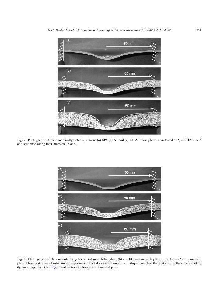
Fig. 7. Photographs of the dynamically tested specimens (a) M9, (b) A4 and (c) B4. All these plates were tested at I0 = 13 kN s m�2
and sectioned along their diametral plane.
Fig. 8. Photographs of the quasi-statically tested: (a) monolithic plate, (b) c = 10 mm sandwich plate and (c) c = 22 mm sandwichplate. These plates were loaded until the permanent back-face deflection at the mid-span matched that obtained in the correspondingdynamic experiments of Fig. 7 and sectioned along their diametral plane.
D.D. Radford et al. / International Journal of Solids and Structures 43 (2006) 2243–2259 2251

2252 D.D. Radford et al. / International Journal of Solids and Structures 43 (2006) 2243–2259
membrane action, with stationary plastic hinges at the periphery of the indenter and at the supports (asevidenced by the discontinuity in inclination of the plates at those locations).
4. Finite element simulations
Comparisons of the finite element (FE) simulations and the measured responses of the monolithic andsandwich plates are presented in this section. All computations were performed using the explicit time inte-gration version of the commercially available finite element code ABAQUS2 (version 6.4). The circularplates were modelled using four noded axisymmetric quadrilateral elements with reduced integration(CAX4R in ABAQUS notation). Clamped boundary conditions, with vanishing displacements in the radialand tangential directions, were prescribed on the outer radius of the plate, r = R. Dynamic loading of eachplate was simulated by impact of a foam projectile, as described subsequently. Typically, there were 160elements along the radius of each plate and approximately three elements per millimetre through the thick-ness of the face sheets. The prescription employed to set the mesh density in the foam core (and foam pro-jectile) is given in Appendix A. Mesh sensitivity studies revealed that further refinements did notappreciably improve the accuracy of the calculations.
The cylindrical foam projectiles of diameter 28.5 mm were also modelled using CAX4R axisymmet-ric elements, with contact between the outer surface of the projectile and the top surface of the platesmodelled by a frictionless contact surface as provided by ABAQUS. At the start of the simulation, theprojectile was imparted with a uniform initial velocity v0 and was brought into contact with the plate atits mid-span.
4.1. Constitutive description
The AISI 304 stainless steel face sheets of the sandwich plates were modelled by J2-flow theory ratedependent solids of density qf = 8060 kg m�3, Young�s modulus E = 210 GPa and Poisson ratio m = 0.3.The uniaxial tensile true stress versus equivalent plastic strain curves at plastic strain rates 10�3 s�1
6 _ep 6 104 s�1 were tabulated in ABAQUS using the prescription described in Section 2.2. Reference cal-culations were also performed, with the rate dependence of the AISI 304 stainless steel neglected by settingRð_epÞ=1 in Eq. (1). Thus, these rate independent calculations made direct use of the quasi-static tensilestress versus strain response of the AISI 304 stainless steels (Fig. 3b).
The foam core and the projectile were modelled as a compressible continuum using the metal foam con-stitutive model of Deshpande and Fleck (2000). Write sij as the usual deviatoric stress and the von Miseseffective stress as re �
ffiffiffiffiffiffiffiffiffiffiffiffiffiffiffiffi3sijsij=2
p. The isotropic yield surface for the metal foam is specified by
2 Hi
r� Y ¼ 0; ð2Þ
where the equivalent stress r is a homogeneous function of re and mean stress rm � rkk/3 according tor2 � 1
1þ a=3ð Þ2r2e þ a2r2
m
� �. ð3Þ
The material parameter a denotes the ratio of deviatoric strength to hydrostatic strength, and the normal-isation factor on the right-hand side of relation (3) is chosen such that r denotes the stress in a uniaxialtension or compression test. An over-stress model is employed with the yield stress Y specified by
Y ¼ g _ep þ rc; ð4Þ
bbit, Karlsson and Sorensen Inc.

D.D. Radford et al. / International Journal of Solids and Structures 43 (2006) 2243–2259 2253
where g is the viscosity, _epthe plastic strain rate (work conjugate to rÞ, and rcðepÞ is the static uniaxial stress
versus plastic strain relation. Normality of plastic flow is assumed, and this implies that the ‘‘plasticPoisson�s ratio’’ mp ¼ �_ep22=_e
p11 for uniaxial compression in the 1-direction is given by
Fig. 9.sandwsandw
mp ¼1=2� a=3ð Þ2
1þ a=3ð Þ2. ð5Þ
In the simulations, the Alporas foam is assumed to have a Young�s modulus Ec = 1.0 GPa, an elasticPoisson�s ratio m = 0.3 and a plastic Poisson�s ratio mp = 0 (Ashby et al., 2000). The static yield strengthrc versus equivalent plastic strain ep history is calibrated using the compressive stress versus strain responsespresented in Fig. 3a. Data from the 22 mm thick foam specimen is used for the foam cores of thicknessc = 22 mm and for the projectiles, while data from the 10 mm thick specimen is employed to model thefoam core of thickness c = 10 mm. A prescription for the viscosity g is given in Appendix A.
The geometries of the simulated monolithic and sandwich plates match those of the experiments (cf.Section 2.1), with the density of the sandwich cores taken to be qc = 432 kg m�3 and 428 kg m�3, for thesandwich plates of core thickness c = 22 mm and 10 mm, respectively. The density and length of the foamprojectiles are as listed in Table 1.
4.2. Comparison of finite element predictions and measurements
Unless otherwise stated, all calculations reported in this study have been performed with the rate depen-dent constitutive response for the AISI 304 stainless steel. Sample FE predictions of the mid-span deflectionversus time histories of the monolithic plate specimen M9 and the sandwich plate specimen B4 (c = 22 mm)are plotted in Fig. 9, with I0 = 13 kN s m�2 in both cases. The figure shows the mid-span deflection of theback-face of the monolithic plate and of both front and back faces of the sandwich plate. The deflectiontime histories indicate that only small elastic vibrations occur after the peak deflection has been attained.Moreover, the peak deflection is approximately equal to the final permanent deflection for both the mono-lithic and sandwich plates.
0.0 0.5 1.0 1.5 2.00
5
10
15
20
25
30
mid
-spa
nde
flect
ion
(mm
)
time (ms)
front face of sandwich plate
back face of monolithic plate
back face of sandwich plate
Finite element predictions of the mid-span deflection versus time histories of monolithic plate specimen M9 and c = 22 mmich plate specimen B4. The figure shows the mid-span deflection of the back-face of the monolithic plate, and of both faces of theich plate. I0 = 13 kN s m�2.

2254 D.D. Radford et al. / International Journal of Solids and Structures 43 (2006) 2243–2259
The predicted and measured mid-span, back-face deflections of the monolithic plates are shown inFig. 10. The predictions are given for both the rate dependent and rate independent constitutive descrip-tions of the AISI 304 stainless steel. The permanent deflections in the FE calculations are estimated by aver-aging the displacements near the end of the calculations (over the time interval t = 1.5–3.0 ms). It isconcluded that the rate dependent FE model predicts the permanent deflection to reasonable accuracy, witha slight over-prediction at high values of I0. On the other hand, the rate independent model substantiallyover-predicts the experimental measurements, especially for high I0.
Similar comparisons of the predicted and measured permanent mid-span deflections are shown inFig. 11 for the back-face of the sandwich plates. Again, good agreement between the rate dependent FEpredictions and the measurements is seen. The FE predictions of the final core compression ec have beenincluded in Fig. 6; these predictions assume the rate dependent model for the AISI 304 face sheets. TheFE simulations predict the measurements with reasonable accuracy, but give a slight over-prediction ofec at low I0.
4.3. Pressure versus time histories exerted by foam projectiles
The pressure versus time history exerted by the foam projectile on a structure depends upon the foamprojectile: (i) density qp, (ii) length l0, (iii) compressive stress versus strain response of the foam, and (iv)projectile velocity v0 (Radford et al., 2005). The analysis of Radford et al. (2005) suggests that metal foamprojectiles exert a rectangular pressure versus time pulse of magnitude
p0 ¼ rc þqpv
20
eDð6Þ
and duration
s ¼ l0eDv0
; ð7Þ
on a rigid stationary target. Here, rc and eD are the plateau stress and nominal densification strain of thefoam, respectively. This pressure versus time history, however, is sensitive to the structural response of the
0 2 4 6 8 10 12 140
5
10
15
20
mid
-spa
nba
ckfa
cede
flect
ion
(mm
)
I0
= ρp
l0v
0(kNs m-2)
FE (rate independent)
FE (rate dependent)
measurement
Fig. 10. Measured and predicted back-face deflections for the monolithic plates.

0 2 4 6 8 10 12 140
5
10
15
20
I0
= ρpl0v
0(kNs m-2)
FE (rate dependent)
mid
-spa
nba
ckfa
cede
flect
ion
(mm
)
measurement
FE (rate independent)
0 2 4 6 8 10 12 140
5
10
15
FE (rate dependent)
mid
-spa
nba
ckfa
cede
flect
ion
(mm
)
I0
= ρpl0v
0(kNs m-2)
measurement
FE (rate independent)
(a)
(b)
Fig. 11. Measured and predicted back-face deflections for the (a) c = 10 mm and (b) c = 22 mm sandwich plates.
D.D. Radford et al. / International Journal of Solids and Structures 43 (2006) 2243–2259 2255
target: a decrease in the mechanical impedance of the target leads to a decrease in the applied pressure andto an increase in the pulse duration. Thus, it is unclear whether the observed differences in response of thevarious monolithic and sandwich plates for a given I0 are due to differences in their intrinsic impact resis-tance, or a result of the application of different pressure time histories on the plates. We shall employ the FEcalculations to clarify this ambiguity.
The pressure versus time history exerted by the foam projectile on the plates is derived from the FE sim-ulations as
pðtÞ ¼ qpl0 _�vðtÞ; ð8Þ
where �vðtÞ is the average axial velocity of the foam projectile at time t, and the over-dot denotes time dif-ferentiation. Momentum conservation implies that,

Fig. 12plate s
2256 D.D. Radford et al. / International Journal of Solids and Structures 43 (2006) 2243–2259
I0 ¼Z 1
0
pðtÞdt. ð9Þ
The accuracy of the pressure versus time histories, as extracted from the FE calculations using Eq. (8), wasconfirmed by performing additional FE calculations on the monolithic and sandwich plates with the pres-sure transients taken as the loading. Both the rate dependent and rate independent versions of the consti-tutive law for the AISI 304 face sheets were employed. In all cases, the deflections were within 0.5% of thoseobtained previously using the projectile loading.
The calculated pressure versus time histories exerted by the foam projectiles on the monolithic plate M9,the sandwich plate A4 (c = 10 mm) and on the sandwich plate B4 (c = 22 mm) are plotted in Fig. 12; ineach case I0 = 13 kN s m�2. (All FE calculations detailed here and subsequently have been performed usingthe strain rate sensitive model for the AISI 304 stainless steel.) While the differences between the pressureversus time histories are small, it is clear from Fig. 12 that the pressure pulse duration is shortest for themonolithic plate. Consequently, the average pressure exerted by the foam projectile on the monolithic plateis highest.
We quantify the effect of these differences in the pressure versus time histories upon the structural re-sponse of the plates in three steps. First, the pressure versus time histories exerted on the sandwich platesby the foam projectiles are extracted from the FE simulations using the above prescription. Second, thepressure versus time histories are applied to the monolithic plate on a central patch of diameterd = 28.5 mm, and the resulting mid-span deflection versus time history is recorded for a period of 3 ms.And third, the permanent mid-span deflection of the monolithic plate is evaluated from these deflection ver-sus time histories.
FE predictions of the permanent back-face deflections at mid-span of the c = 10 mm sandwich plate andof the monolithic plate are plotted in Fig. 13a, each for the case of direct loading by the foam projectiles.Additionally, FE predictions are given for the mid-span deflection of the monolithic plates due to the pres-sure versus time loading history as exerted by the foam projectile on the sandwich plate; these predictionsare labelled �pressure loading�. Imposition of the pressure loading results in a slight reduction in themid-span deflections of the monolithic plates, especially at large I0. However, the overall conclusion that
0.00 0.05 0.10 0.15 0.200
50
100
150
200
monolithic platesandwich plate, c = 10 mmsandwich plate, c = 22 mm
pres
sure
(MP
a)
time (ms)
. The predicted pressure versus time histories exerted by the foam projectiles on the monolithic specimen M9, and the sandwichpecimens A4 (c = 10 mm) and B4 (c = 22 mm). I0 = 13 kN s m�2.

0 2 4 6 8 10 12 140
5
10
15
20
mid
-spa
nba
ckfa
cede
flect
ion
(mm
)
I0
= ρp
l0v
0(kNs m–2)
monolithic plate (projectile loading)
monolithic plate (pressure loading)
sandwich plate(projectile loading)
0 2 4 6 8 10 12 140
5
10
15
20
monolithic plate (pressure loading)
monolithic plate (projectile loading)
mid
-spa
nba
ckfa
cede
flect
ion
(mm
)
I0
= ρp
l0v
0(kNs m–2)
sandwich plate(projectile loading)
(a)
(b)
Fig. 13. Predicted back-face deflections at mid-span. (a) Sandwich plate (c = 10 mm) and monolithic plate loaded by projectile, andmonolithic plate loaded by pressure transient. (b) Sandwich plate (c = 22 mm) and monolithic plate loaded by projectile, andmonolithic plate loaded by pressure transient.
D.D. Radford et al. / International Journal of Solids and Structures 43 (2006) 2243–2259 2257
sandwich plates outperform monolithic plates at high values of I0 remains unchanged. Similar comparisonsof the FE predictions of the permanent back-face deflections at mid-span of the c = 22 mm sandwich platesand monolithic plates due to loading by foam projectiles are shown in Fig. 13b. Included in the figure arethe associated permanent mid-span deflections of the monolithic plates loaded by the pressure versus timehistories exerted by the foam projectile on the c = 22 mm sandwich plates. Again, the pressure loading re-sults in a small reduction in the mid-span deflections of the monolithic plates at high values of I0, but theoverall conclusion that the c = 22 mm sandwich plates outperform the monolithic plates remains un-changed. We conclude that foam projectiles are a convenient laboratory tool for investigating the dynamicresponse of such monolithic and sandwich plates.
2258 D.D. Radford et al. / International Journal of Solids and Structures 43 (2006) 2243–2259
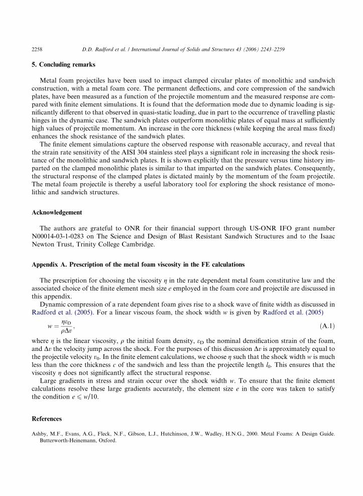
5. Concluding remarks
Metal foam projectiles have been used to impact clamped circular plates of monolithic and sandwichconstruction, with a metal foam core. The permanent deflections, and core compression of the sandwichplates, have been measured as a function of the projectile momentum and the measured response are com-pared with finite element simulations. It is found that the deformation mode due to dynamic loading is sig-nificantly different to that observed in quasi-static loading, due in part to the occurrence of travelling plastichinges in the dynamic case. The sandwich plates outperform monolithic plates of equal mass at sufficientlyhigh values of projectile momentum. An increase in the core thickness (while keeping the areal mass fixed)enhances the shock resistance of the sandwich plates.
The finite element simulations capture the observed response with reasonable accuracy, and reveal thatthe strain rate sensitivity of the AISI 304 stainless steel plays a significant role in increasing the shock resis-tance of the monolithic and sandwich plates. It is shown explicitly that the pressure versus time history im-parted on the clamped monolithic plates is similar to that imparted on the sandwich plates. Consequently,the structural response of the clamped plates is dictated mainly by the momentum of the foam projectile.The metal foam projectile is thereby a useful laboratory tool for exploring the shock resistance of mono-lithic and sandwich structures.
Acknowledgement
The authors are grateful to ONR for their financial support through US-ONR IFO grant numberN00014-03-1-0283 on The Science and Design of Blast Resistant Sandwich Structures and to the IsaacNewton Trust, Trinity College Cambridge.
Appendix A. Prescription of the metal foam viscosity in the FE calculations
The prescription for choosing the viscosity g in the rate dependent metal foam constitutive law and theassociated choice of the finite element mesh size e employed in the foam core and projectile are discussed inthis appendix.
Dynamic compression of a rate dependent foam gives rise to a shock wave of finite width as discussed inRadford et al. (2005). For a linear viscous foam, the shock width w is given by Radford et al. (2005)
w ¼ geDqDv
; ðA:1Þ
where g is the linear viscosity, q the initial foam density, eD the nominal densification strain of the foam,and Dv the velocity jump across the shock. For the purposes of this discussion Dv is approximately equal tothe projectile velocity v0. In the finite element calculations, we choose g such that the shock width w is muchless than the core thickness c of the sandwich and less than the projectile length l0. This ensures that theviscosity g does not significantly affect the structural response.
Large gradients in stress and strain occur over the shock width w. To ensure that the finite elementcalculations resolve these large gradients accurately, the element size e in the core was taken to satisfythe condition e 6 w/10.
References
Ashby, M.F., Evans, A.G., Fleck, N.F., Gibson, L.J., Hutchinson, J.W., Wadley, H.N.G., 2000. Metal Foams: A Design Guide.Butterworth-Heinemann, Oxford.

D.D. Radford et al. / International Journal of Solids and Structures 43 (2006) 2243–2259 2259
Dannemann, K.A., Lankford, J., 2000. High strain rate compression of closed-cell aluminium foams. Materials Science andEngineering: A 293 (1–2), 157–164.
Deshpande, V.S., Fleck, N.A., 2000. Isotropic constitutive models for metallic foams. Journal of Mechanics and Physics of Solids 48,1253–1283.
Fleck, N.A., Deshpande, V.S., 2004. The resistance of clamped sandwich beams to shock loading. Journal of Applied Mechanics,ASME 71 (3), 386–401.
Jones, N., 1968. Impulsive loading of a simply supported circular rigid plate. Journal of Applied Mechanics 27, 59.Miyoshi, T., Mukai, T., Higashi, K., 2002. Energy absorption in closed-cell Al–Zn–Mg–Ca–Ti foam. Materials Transactions 43 (7),
1778–1781.Qiu, X., Deshpande, V.S., Fleck, N.A., 2005. Impulsive loading over a central portion of clamped sandwich beams. Journal of
Mechanics and Physics of Solids 53, 1015–1046.Radford, D.D., Deshpande, V.S., Fleck, N.A., 2005. The use of metal foam projectiles to simulate shock loading on a structure.
International Journal of Impact Engineering 31, 1152–1171.Radford, D.D., Fleck, N.A., Deshpande, V.S., in press. The response of clamped sandwich beams subjected to shock loading.
International Journal of Impact Engineering.Rathbun, H.J., Radford, D.D., Xue, Z., Yang, J., Deshpande, V.S., Fleck, N.A., Hutchinson, J.W., Zok, F.W., Evans, A.G., in press.
A dynamic probe for validating simulations of shock loaded metallic sandwich panels. International Journal of Solids andStructures.
Stout, M.G., Follansbee, P.S., 1986. Strain rate sensitivity, strain hardening, and yield behavior of 304L stainless steel. Transactions ofASME: Journal of Engineering Materials Technology 108, 344–353.
Symmonds, P.S., 1954. Large plastic deformations of beams under blast type loading. Second US National Congress of AppliedMechanics.
Wang, A.J., Hopkins, H.G., 1954. On the plastic deformation of built-in circular plates under impulsive load. Journal of Mechanicsand Physics of Solids 3, 22–37.
Xue, Z., Hutchinson, J.W., 2003. Preliminary assessment of sandwich plates subject to blast loads. International Journal of MechanicalSciences 45, 687–705.
Xue, Z., Hutchinson, J.W., 2004. A comparative study of blast-resistant metal sandwich plates. International Journal of ImpactEngineering 30, 1283–1305.


![Mechanical response of metallic honeycomb sandwich … the same areal density. ... dimensional Kagome architectures [17,18], ... that is initially close to the detonation velocity](https://img.pdfslide.us/doc/110x75/5ab01e6c7f8b9a6b308e237f/mechanical-response-of-metallic-honeycomb-sandwich-the-same-areal-density-.jpg)