Embed Size (px)
Citation preview
This is an electronic reprint of the original article.This reprint may differ from the original in pagination and typographic detail.
Powered by TCPDF (www.tcpdf.org)
This material is protected by copyright and other intellectual property rights, and duplication or sale of all or part of any of the repository collections is not permitted, except that material may be duplicated by you for your research use or educational purposes in electronic or print form. You must obtain permission for any other use. Electronic or print copies may not be offered, whether for sale or otherwise to anyone who is not an authorised user.
Reinaldo Goncalves, Bruno; Romanoff, JaniSize-dependent modelling of elastic sandwich beams with prismatic cores
Published in:International Journal of Solids and Structures
DOI:10.1016/j.ijsolstr.2017.12.001
Published: 01/04/2018
Document VersionPublisher's PDF, also known as Version of record
Published under the following license:CC BY-NC-ND
Please cite the original version:Reinaldo Goncalves, B., & Romanoff, J. (2018). Size-dependent modelling of elastic sandwich beams withprismatic cores. International Journal of Solids and Structures, 136, 28-37.https://doi.org/10.1016/j.ijsolstr.2017.12.001
International Journal of Solids and Structures 136–137 (2018) 28–37
Contents lists available at ScienceDirect
International Journal of Solids and Structures
journal homepage: www.elsevier.com/locate/ijsolstr
Size-dependent modelling of elastic sandwich beams with prismatic
cores
Bruno Reinaldo Goncalves ∗, Jani Romanoff
Aalto University, Department of Mechanical Engineering, Aalto FI-0 0 076, Finland
a r t i c l e i n f o
Article history:
Received 17 August 2017
Revised 10 November 2017
Available online 8 December 2017
Keywords:
Size effect
Sandwich panels
Couple stress theory
Prismatic cores
a b s t r a c t
Sandwich panel strips with prismatic cores are modelled using the modified couple stress theory and
their elastic size-dependent bending behaviour investigated. Compatibility between the discrete sand-
wich and continuum beam kinematics is first discussed. A micromechanics-based framework to estimate
effective mechanical properties is provided and unit cell models constructed with elementary beam el-
ements to determine the stiffness parameters of various prismatic cores. Numerical studies show that
the modified couple stress Timoshenko beam enhances the static deflection predictions of the classical
Timoshenko model. A sensitivity measure based on structural ratios is proposed to estimate the influence
of size effects in the global beam-level response. The parameters governing size effects in elastic sand-
wich beams are identified: Face-to-core thickness ratio, core density and topology, vertical corrugation
order and set of load and boundary conditions. Size effects are shown more pronounced in low-density
cores that rely on corrugation bending as shear-carrying mechanism. Based on the external load, bound-
ary conditions and sensitivity factor, one can assess whether size effects are non-negligible in a given
engineering structure.
© 2017 The Authors. Published by Elsevier Ltd.
This is an open access article under the CC BY-NC-ND license.
( http://creativecommons.org/licenses/by-nc-nd/4.0/ )
t
s
a
(
t
t
w
a
c
s
o
t
s
a
n
t
u
c
1. Introduction
All-metal prismatic sandwich panels are a lightweight alterna-
tive to conventional plates used in civil, mechanical, vehicle engi-
neering and other applications. The structure is composed of two
skins separated by a low-density, visibly discrete core, which gov-
erns the mechanical properties and can be tailored based on the
application requirements. In the marine industry, sandwich pan-
els with various cores have been studied to substitute the conven-
tional plate with ribs arrangement ( Kujala and Klanac, 2005 ). Pris-
matics such as the X- and Y-cores have been used for the double
hull design due to their relative simple production and impact per-
formance ( Naar et al., 2002; Ehlers et al., 2012 ). Advances in manu-
facturing encouraged the development of micro-architectured pris-
matics, whose multifunctional capacity includes superior heat and
energy absorption performances ( Valdevit et al., 2004; Gu et al.,
2001; Evans et al., 2001 ). Overall, the discrete character of pris-
matic cores leads to computational modelling challenges due to
the presence of consecutive length scales, as representing their ac-
tual geometry is usually inefficient. Effective continuum models are
∗ Corresponding author.
E-mail address: [email protected] (B. Reinaldo Goncalves).
a
i
p
https://doi.org/10.1016/j.ijsolstr.2017.12.001
0020-7683/© 2017 The Authors. Published by Elsevier Ltd. This is an open access article u
herefore sought to facilitate the analysis and optimization of such
tructures.
In a broad sense, continuum models of sandwich structures
re divided into ply-level layerwise and equivalent single layer
ESL) categories; see Carrera and Brischetto (2009) for details. In
he context of low-complexity single-layer models, the sandwich
heory (e.g. Allen, 1969; Zenkert, 1995 ) is the classical reference,
here deflections are decomposed into bending and shear terms
nd compatibility between faces and core is invoked. More re-
ently, the homogenization theory based on asymptotic expan-
ion of cell quantities has been used to describe the response
f periodic structures such as sandwich panels ( Hassani and Hin-
on, 1998; Buannic et al., 2003 ) based on classical and first-order
hear deformation theories. Prismatic sandwich panels compose
n application case where relatively flexible cores result in non-
egligible local effects and size dependency. An enhanced model is
herefore needed to include the internal cell stiffness to the contin-
um, improving the shear stress distribution description near dis-
ontinuities and capturing size effects.
In recent years, microstructure-dependent theories re-emerged
s an alternative to account for the influence of different scales
n the global structural response. Liu and Su (2009) have pro-
osed using a two-dimensional couple stress model and the-
nder the CC BY-NC-ND license. ( http://creativecommons.org/licenses/by-nc-nd/4.0/ )
B. Reinaldo Goncalves, J. Romanoff / International Journal of Solids and Structures 136–137 (2018) 28–37 29
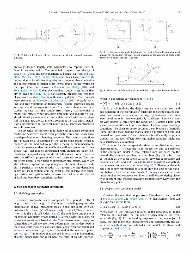
Fig. 1. Global and local scales of the continuum model with adopted conventions
indicated.
o
f
Y
2
t
a
t
R
o
o
w
l
w
s
m
g
i
t
a
m
s
a
f
b
s
m
e
p
a
e
b
o
o
2
2
l
i
o
i
t
e
s
t
v
s
o
Fig. 2. (a) Constant shear angle definition in the classical first-order continuum and
internal cell fluctuations (b) local rotation measure as the variation of shear angle
between cell boundaries ∂�− and ∂�+ .
Fig. 3. Kinematics of deformation of the modified couple stress Timoshenko beam.
w
w
o
v
a
e
s
c
f
i
c
b
d
i
s
b
b
i
c
t
t
w
d
2
i
b
U
w
r
e
s
i
i
ε
retically derived length scale parameters to capture size ef-
ects in cellular solids. The modified couple stress theory of
ang et al. (2002) and generalizations to beams (e.g. Park and Gao,
006; Ma et al., 2008; Reddy, 2011 ) and plates have received at-
ention due to its relative simplicity in parameter characterization
nd interpretation of higher-order terms, unlike earlier works on
he topic. It has been shown in Romanoff and Reddy (2014) and
omanoff et al. (2015) that the modified couple stress beam the-
ry as given in Reddy (2011) satisfactorily predicts the response
f web-core sandwich beams with semi-rigid joints. The concepts
ere extended by Reinaldo Goncalves et al. (2017) to study buck-
ing and free vibrations of transversely flexible sandwich beams
ith web- and homogeneous cores. The results obtained in these
tudies indicate that the couple stress theory has potential to
odel size effects, while retaining simplicity and requiring a sin-
le additional parameter that can be determined with sound phys-
cal meaning. Yet, the parameters governing the size effect magni-
ude and relevance in practical modelling of sandwich structures
re still unknown.
The objective of this work is to define an enhanced continuum
odel for sandwich beams with prismatic cores and study their
ize-dependent elastic bending response. The main assumptions
re followed by a description of the global scale beam, which is
ounded on the modified couple stress theory. A micromechanics-
ased framework to determine effective stiffness properties is then
hown. Unit cell models constructed with elementary beam ele-
ents and analyzed using the direct stiffness method are used to
stimate stiffness properties of various prismatic cores. The cou-
le stress beam is then used to investigate size effects, which are
lso validated against corresponding discrete finite element mod-
ls. In particular, structural ratios that govern the size-dependent
ehaviour are identified, and the effect of cell density, core topol-
gy, vertical corrugation order, face-to-core thickness ratio and set
f load and boundary conditions studied.
. Size-dependent sandwich continuum
.1. Modelling assumptions
Consider sandwich beams composed of n periodic cells of
ength s to a total length L . Continuum modelling requires the
dentification of two interacting scales, global and local, with co-
rdinates ( x, z ) and ( x l , z l ) respectively, x = ( i + 1/2) s + x l , where
= 0,1.. n is the unit cell index ( Fig. 1 ). The cells have one plane of
opological symmetry whose normal is aligned with the x -axis. An
quivalent continuum based on the Timoshenko beam theory as-
umes that the cell average shear deformation can be described in
he global scale through a constant shear angle with horizontal and
ertical components, γ xz = γ h + γ v , located at the reference point,
ee Fig. 2 (a). This implies that the cell internal shear fluctuations
f order higher than one must have the form of an odd function,
hich in deflections corresponds to ( Fig. 2 (a))
l (x l )
= − w
l (−x l
)+ 2 γh x
l in � (1)
If Eq. (1) is fulfilled, the derivatives are alternating even and
dd functions of the coordinate x l , such that the shear-induced cur-
ature and stresses also have zero average by definition; the equiv-
lent continuum is then energetically consistent. Sandwich pan-
ls with prismatic cores have the condition (1) violated near local
hear discontinuities such as concentrated loads or slope boundary
onditions. The shear response becomes a combination of periodic
rame-like and local bending modes, being a function of beam and
nternal cell parameters. Once this effect is sufficiently large, ex-
luding the localized effects from the global response might not
e a satisfactory assumption.
To account for the non-periodic shear stress distribution near
iscontinuities, it is necessary to introduce the unit cell stiffness
n the continuum model. A local rotation measure based on the
econd displacement gradient is used here ( Eq. 3 ), which can
e thought as the shear angle variation between consecutive cell
oundaries ∂�− and ∂�+ as additional kinematical compatibil-
ty between discrete and continuum ( Fig. 2 (b)). That way, the unit
ell is no longer represented by a point only, but also by the varia-
ion between two consecutive points. Assuming a constant cell ro-
ation implies homogeneous cell internal stiffness, rendering piece-
ise constant local stresses decaying asymptotically away from the
iscontinuity point.
.2. Couple stress continuum model
Consider the modified couple stress Timoshenko beam model
n Ma et al. (2008) and Reddy (2011) . The displacement field can
e expressed in the form
x ( x, z ) = zφx ( x ) , U z ( x, z ) = w ( x ) (2)
here φx ( x ) is the transverse rotation of the cross-section at the
eference axis and w ( x ) the transverse displacement of the refer-
nce axis ( Fig. 3 ). As the bending response is the only object of
tudy, the mid-plane axial displacement and consequently the ax-
al stress resultant are not included in the model. The strain field
s given by ( Reddy, 2011 )
xx = z ∂ φx
∂x , γxz = φx +
∂w
∂x , χxy =
1
4
(∂ φx
∂x − ∂ 2 w
∂ x 2
)(3)
30 B. Reinaldo Goncalves, J. Romanoff / International Journal of Solids and Structures 136–137 (2018) 28–37
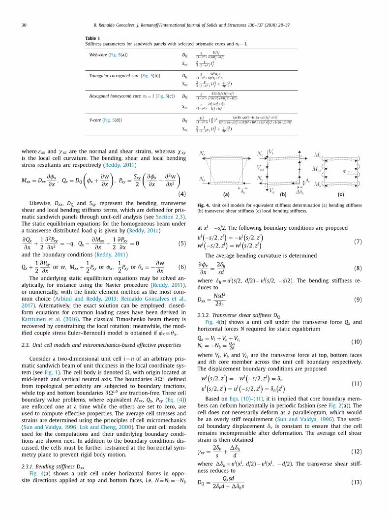
Table 1
Stiffness parameters for sandwich panels with selected prismatic cores and n c = 1.
Web-core ( Fig. 5 (a)) D Q E
( 1 −υ2 )
2 t 3 c t 3 f
s ( 2 dt 3 f + st 3 c )
S xy 2 3
E ( 1 −υ2 )
t 3 f
Triangular corrugated core ( Fig. 5 (b)) D Q E
( 1 −υ2 )
4 d 2 s t f t c 8 p 3 t f + s 3 t c
S xy 2 3
E ( 1 −υ2 )
( t 3 f
+
s 4 p
t 3 c )
Hexagonal honeycomb core, n c = 1 ( Fig. 5 (c)) D Q E
( 1 −υ2 )
432 t 3 f t 3 c ( 2 t
3 f + t 3 c )
s 2 ( 63 t 6 f +48 t 3
f t 3 c +8 t 6 c )
S xy E
( 1 −υ2 )
2 t 3 f ( 2 t 3 c + t 3 f )
3 t 3 f +4 t 3 c
Y-core ( Fig. 5 (d)) D Q Et 3 c
( 1 −υ2 ) s ( d
h ) 2
3 p( 8 h + p ) t 6 f +4 s ( 3 h + p ) t 3
f t 3 c + s 2 t 6 c
12 hp( 2 h + p ) t 6 f + s ( 12 h 2 +16 hp+3 p 2 ) t 3
f t 3 c +2( 2 h + p ) s 2 t 6 c
S xy 2 3
E ( 1 −υ2 )
( t 3 f
+
s 4 p
t 3 c )
Fig. 4. Unit cell models for equivalent stiffness determination (a) bending stiffness
(b) transverse shear stiffness (c) local bending stiffness.
a
u
w
w
d
D
2
h
Q
N
w
a
T
b
c
b
c
r
s
γ
w
n
where εxx and γ xz are the normal and shear strains, whereas χ xy
is the local cell curvature. The bending, shear and local bending
stress resultants are respectively ( Reddy, 2011 )
M xx = D xx ∂ φx
∂x , Q x = D Q
(φx +
∂w
∂x
), P xy =
S xy
2
(∂ φx
∂x − ∂ 2 w
∂ x 2
)
(4)
Likewise, D xx , D Q and S xy represent the bending, transverse
shear and local bending stiffness terms, which are defined for pris-
matic sandwich panels through unit-cell analysis (see Section 2.3 ).
The static equilibrium equations for the homogeneous beam under
a transverse distributed load q is given by ( Reddy, 2011 )
∂ Q x
∂x +
1
2
∂ 2 P xy
∂ x 2 = −q, Q x − ∂ M xx
∂x − 1
2
∂ P xy
∂x = 0 (5)
and the boundary conditions ( Reddy, 2011 )
Q x +
1
2
∂ P xy
∂x or w, M xx +
1
2
P xy or φx , 1
2
P xy or θx = −∂w
∂x (6)
The underlying static equilibrium equations may be solved an-
alytically, for instance using the Navier procedure ( Reddy, 2011 ),
or numerically, with the finite element method as the most com-
mon choice ( Arbind and Reddy, 2013; Reinaldo Goncalves et al.,
2017 ). Alternatively, the exact solution can be employed; closed-
form equations for common loading cases have been derived in
Karttunen et al. (2016) . The classical Timoshenko beam theory is
recovered by constraining the local rotation; meanwhile, the mod-
ified couple stress Euler–Bernoulli model is obtained if φx = θ x .
2.3. Unit cell models and micromechanics-based effective properties
Consider a two-dimensional unit cell i = n of an arbitrary pris-
matic sandwich beam of unit thickness in the local coordinate sys-
tem (see Fig. 1 ). The cell body is denoted �, with origin located at
mid-length and vertical neutral axis. The boundaries ∂�± defined
from topological periodicity are subjected to boundary tractions,
while top and bottom boundaries ∂�t,b are traction-free. Three cell
boundary value problems, where equivalent M xx , Q x , P xy ( Eq. (4 ))
are enforced one at a time while the others are set to zero, are
used to compute effective properties. The average cell stresses and
strains are determined using the principles of cell micromechanics
( Sun and Vaidya, 1996; Lok and Cheng, 20 0 0 ). The unit cell models
used for the computations and their underlying boundary condi-
tions are shown next. In addition to the boundary conditions dis-
cussed, the cells must be further restrained at the horizontal sym-
metry plane to prevent rigid body motion.
2.3.1. Bending stiffness D xx
Fig. 4 (a) shows a unit cell under horizontal forces in oppo-
site directions applied at top and bottom faces, i.e. N = N t = −N
b Dt x l = −s /2. The following boundary conditions are proposed
l (−s/ 2 , z l
)= −u
l (s/ 2 , z l
)
l (−s/ 2 , z l
)= w
l (s/ 2 , z l
) (7)
The average bending curvature is determined
∂φx
∂x =
2 δh
sd (8)
here δh = u l ( s /2, d /2) − u l ( s /2, −d /2). The bending stiffness re-
uces to
xx =
Ns d 2
2 δh
(9)
.3.2. Transverse shear stiffness D Q
Fig. 4 (b) shows a unit cell under the transverse force Q x and
orizontal forces N required for static equilibrium
x = V t + V b + V c i
t = −N b =
Q x s 2 d
(10)
here V t , V b and V c i are the transverse force at top, bottom faces
nd i th core member across the unit cell boundary respectively.
he displacement boundary conditions are proposed
w
l (s/ 2 , z l
)= −w
l (−s/ 2 , z l
)= δv
u
l (s/ 2 , z l
)= u
l (−s/ 2 , z l
)= δh
(z l ) (11)
Based on Eqs. (10 )–(11) , it is implied that core boundary mem-
ers can deform horizontally in periodic fashion (see Fig. 2 (a)). The
ell does not necessarily deform as a parallelogram, which would
e an overly stiff requirement ( Sun and Vaidya, 1996 ). The verti-
al boundary displacement δv is constant to ensure that the cell
emains incompressible after deformation. The average cell shear
train is then obtained
xz =
2 δv
s +
�δh
d (12)
here �δh = u l (x l , d /2) − u l (x l , − d /2). The transverse shear stiff-
ess reduces to
Q =
Q x sd (13)
2 δv d + �δh s
B. Reinaldo Goncalves, J. Romanoff / International Journal of Solids and Structures 136–137 (2018) 28–37 31
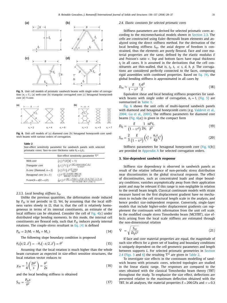
Fig. 5. Unit cell models of prismatic sandwich beams with single order of corruga-
tion ( n c = 1), (a) web-core (b) triangular corrugated core (c) hexagonal honeycomb
core (d) Y-core.
Fig. 6. Unit cell models of (a) diamond core (b) hexagonal honeycomb core sand-
wich beams with various orders of corrugation.
Table 2
Size-effect sensitivity parameter for sandwich panels with selected
prismatic cores; face-to-core thickness ratio k t = t f / t c .
Size-effect sensitivity parameter ∇
2
Web-core 1 3 ( s
L ) 2 ( 2 d
s k 3 t + 1 )
Triangular core 1 12
( s L ) 2 ( t c
d ) 2
( 2 k 3 t + cos α)( cos α3 + k t ) k t cos α3
X-core ( Diamond, n = 2) 1 3 ( s
L ) 2 ( t c
d ) 2
k 3 t + cos αcos α3
Hexagonal core ( n = 1) ( s L ) 2
( k 3 t +2 )( 63 k 6 t +48 k 3 t +8 )
864( 2 k 3 t +1 )( 3 k 3 t +4 )
Y-core ( h = d/ 2 = s /2) 1 24
( s L ) 2
( 4 k 3 t + √
2 )[ 6( 1+ √
2 ) k 6 t +( 9+8 √
2 ) k 3 t +2 √
2 +4 ]
3( 1+4 √
2 ) k 6 t +4( 3+ √
2 ) k 3 t +2
2
b
n
g
l
d
c
r
P
θ
b
l
χ
a
S
2
c
c
a
l
s
t
a
t
s
t
r
g
D
w
s
w
2
b
D
S
a
3
r
n
o
a
p
t
m
n
h
m
p
I
f
t
∇
s
i
b
2
w
i
o
t
p
.3.3. Local bending stiffness S xy
Unlike the previous quantities, the deformation mode induced
y P xy is not periodic in �. Yet, by assuming that the local stiff-
ess varies slowly in �, that is, that the cell is relatively homo-
eneous in terms of its internal constituents, an estimate of the
ocal stiffness can be obtained. Consider the cell of Fig. 4 (c) under
istributed edge bending moments. In this mode, the internal cell
onstituents are flexural only, such that P xy induces purely internal
otations. The couple-stress resultant in Eq. (4) is defined
xy = 2 ( M t + M b + M c i ) (14)
The following slope boundary condition is proposed
x
(s/ 2 , z l
)= −θx
(−s/ 2 , z l
)= θ l (15)
Assuming that the local rotation is much higher than the whole
eam curvature as expected in size-effect sensitive structures, the
ocal rotation vector reduces to
xy =
1
4
(2 θ l
s
)=
θ l
2 s (16)
nd the local bending stiffness is obtained
=
P xy s (17)
xyθ l T
.4. Elastic constants for selected prismatic cores
Stiffness parameters are derived for selected prismatic cores ac-
ording to the micromechanical models shown in Section 2.3 . The
ells are constructed using Euler–Bernoulli beam elements and an-
lyzed using the direct stiffness method. For the derivation of the
ocal bending stiffness S xy , the axial degree of freedom is con-
trained, thus the elements are purely flexural. Face and core ma-
erial properties are the same, defined by the elastic modulus E
nd Poisson’s ratio ν . Top and bottom faces have equal thickness
f in all cases. It is assumed in the derivations that the cell con-
tituents are thin-walled, that is, t f , t c � s, d, h, p . The corruga-
ions are considered perfectly connected to the faces, composing
igid assemblies with combined properties. Based on Eq. (9) , the
lobal bending stiffness is approximated in all cases by
xx ≈ E
1 − υ2
t f d 2
2
(18)
Equivalent shear and local bending stiffness properties for sand-
ich beams with single order of corrugation, n c = 1, ( Fig. 5 ) are
ummarized in Table 1 .
Fig. 6 shows the unit cells of multi-layered sandwich panels
ith diamond and hexagonal honeycomb cores (e.g. Valdevit et al.,
004; Gu et al., 2001 ). The stiffness parameters for diamond core
eams ( Fig. 6 (a)) is given in the compact form
Q =
E (1 − υ2
) 1
2 n c
s d 2 t c
p 3 (19)
xy =
2
3
E (1 − υ2
)(t 3 f +
n c s
4 p t 3 c
)(20)
Stiffness parameters for hexagonal honeycomb core ( Fig. 6 (b))
re provided in Appendix A for selected corrugation orders.
. Size-dependent sandwich response
Stiffness size dependency is observed in sandwich panels as
esult of the relative influence of non-periodic stress distribution
ear discontinuities in the global structural response. The effect
f discontinuities, such as concentrated loads and slope bound-
ry conditions, vanishes asymptotically away from their application
oint and may be relevant if this range is non-negligible in relation
o the overall beam length. Classical continuum models with strain
easure based on the first displacement gradient have no mecha-
ism to include the cell structural length scale in the analysis, and
ence predict size-independent response. Conversely, single-layer
odels that include higher-order displacement gradients can sup-
lement the continuum with information from the unit cell scale.
n the modified couple stress Timoshenko beam (MCSTBT), size ef-
ects arising from the local scale stiffness are estimated through
he non-dimensional relation
=
√
S xy
D Q L 2 (21)
If face and core material properties are equal, the magnitude of
uch size effects for a given set of loading and boundary conditions
s uniquely dependent on the cell geometric parameters and length
etween supports L . For selected prismatic geometries in Section
.4 ( Figs. 5 and 6 ) the resulting ∇
2 are given in Table 2 .
To investigate size effects in the continuum modelling of sand-
ich beams with prismatic cores, selected topologies are studied
n the linear elastic range. The responses are compared to the
nes obtained with the classical Timoshenko beam theory (TBT)
hroughout the study. To emphasize the size effect, deflections are
resented relative to the maximum deflection obtained with the
BT. In all analyses, the material properties E = 206 GPa and ν = 0.3
32 B. Reinaldo Goncalves, J. Romanoff / International Journal of Solids and Structures 136–137 (2018) 28–37
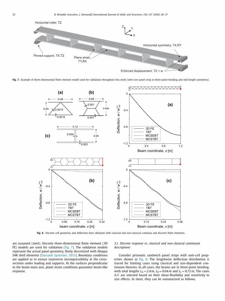
Fig. 7. Example of three-dimensional finite element model used for validation throughout this work (web-core panel strip in three-point bending and mid-length symmetry).
Fig. 8. Discrete cell geometry and deflection lines obtained with classical and non-classical continua and discrete finite elements.
3
d
e
t
t
w
are assumed (steel). Discrete three-dimensional finite element (3D
FE) models are used for validation ( Fig. 7 ). The validation models
represent the actual panel geometry, finely discretized with Abaqus
S4R shell elements ( Dassault Systemes, 2013 ). Boundary conditions
are applied as to ensure transverse incompressibility at the cross-
sections under loading and supports. At the surfaces perpendicular
to the beam main axis, plane strain conditions guarantee beam-like
response.
A
s
.1. Discrete response vs. classical and non-classical continuum
escriptions
Consider prismatic sandwich panel strips with unit-cell prop-
rties shown in Fig. 8 . The lengthwise deflection distribution is
raced for limiting cases using classical and size-dependent con-
inuum theories. In all cases, the beams are in three-point bending,
ith total lengths L A = 2.4 m, L B = 0.64 m and L C = 0.72 m. The cases
-C are selected based on their shear-flexibility and sensitivity to
ize effects. In short, they can be summarized as follows,
B. Reinaldo Goncalves, J. Romanoff / International Journal of Solids and Structures 136–137 (2018) 28–37 33
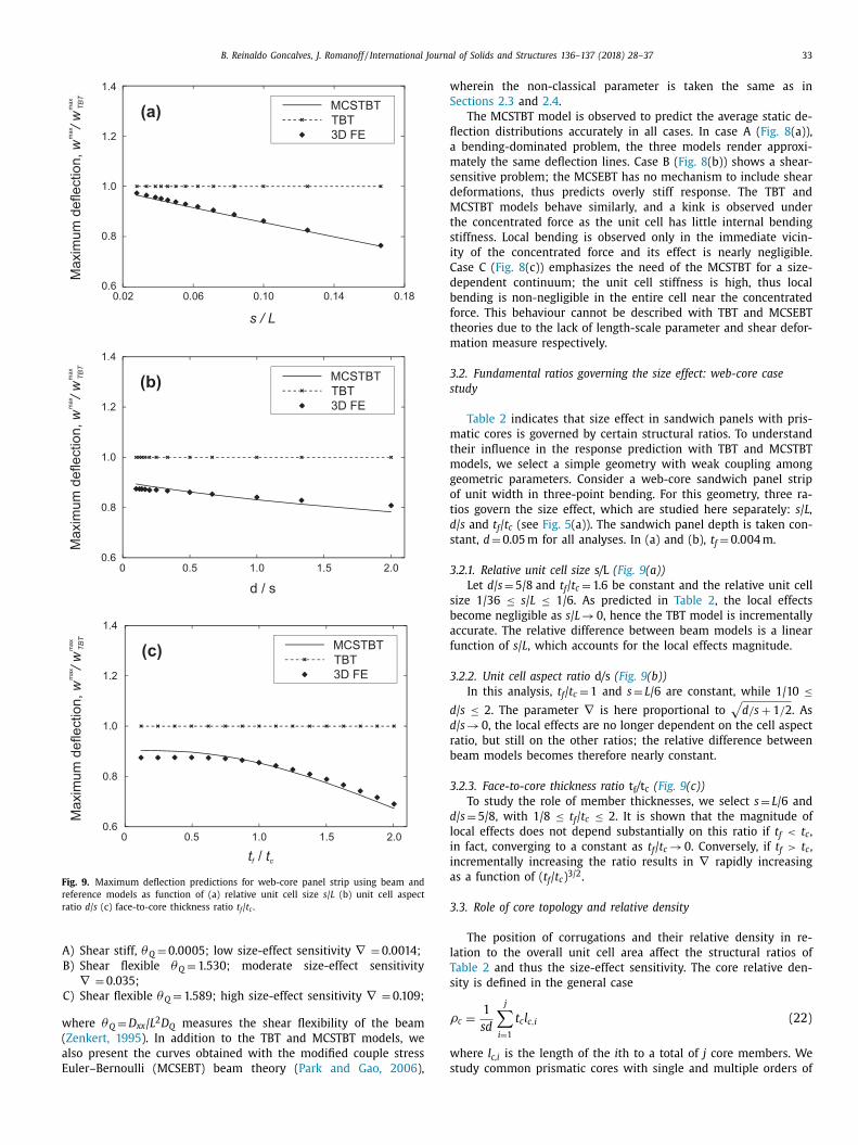
Fig. 9. Maximum deflection predictions for web-core panel strip using beam and
reference models as function of (a) relative unit cell size s / L (b) unit cell aspect
ratio d / s (c) face-to-core thickness ratio t f / t c .
w
(
a
E
w
S
fl
a
m
s
d
M
t
s
i
C
d
b
f
t
m
3
s
m
t
m
g
o
t
d
s
3
s
b
a
f
3
d
d
r
b
3
d
l
i
i
a
3
l
T
s
ρ
w
s
A) Shear stiff, θQ = 0.0 0 05; low size-effect sensitivity ∇ = 0.0014;
B) Shear flexible θQ = 1.530; moderate size-effect sensitivity
∇ = 0.035;
C) Shear flexible θQ = 1.589; high size-effect sensitivity ∇ = 0.109;
here θQ = D xx / L 2 D Q measures the shear flexibility of the beam
Zenkert, 1995 ). In addition to the TBT and MCSTBT models, we
lso present the curves obtained with the modified couple stress
uler–Bernoulli (MCSEBT) beam theory ( Park and Gao, 2006 ),
herein the non-classical parameter is taken the same as in
ections 2.3 and 2.4 .
The MCSTBT model is observed to predict the average static de-
ection distributions accurately in all cases. In case A ( Fig. 8 (a)),
bending-dominated problem, the three models render approxi-
ately the same deflection lines. Case B ( Fig. 8 (b)) shows a shear-
ensitive problem; the MCSEBT has no mechanism to include shear
eformations, thus predicts overly stiff response. The TBT and
CSTBT models behave similarly, and a kink is observed under
he concentrated force as the unit cell has little internal bending
tiffness. Local bending is observed only in the immediate vicin-
ty of the concentrated force and its effect is nearly negligible.
ase C ( Fig. 8 (c)) emphasizes the need of the MCSTBT for a size-
ependent continuum; the unit cell stiffness is high, thus local
ending is non-negligible in the entire cell near the concentrated
orce. This behaviour cannot be described with TBT and MCSEBT
heories due to the lack of length-scale parameter and shear defor-
ation measure respectively.
.2. Fundamental ratios governing the size effect: web-core case
tudy
Table 2 indicates that size effect in sandwich panels with pris-
atic cores is governed by certain structural ratios. To understand
heir influence in the response prediction with TBT and MCSTBT
odels, we select a simple geometry with weak coupling among
eometric parameters. Consider a web-core sandwich panel strip
f unit width in three-point bending. For this geometry, three ra-
ios govern the size effect, which are studied here separately: s / L,
/ s and t f / t c (see Fig. 5 (a)). The sandwich panel depth is taken con-
tant, d = 0.05 m for all analyses. In (a) and (b), t f = 0.004 m.
.2.1. Relative unit cell size s / L ( Fig. 9 (a))
Let d / s = 5/8 and t f / t c = 1.6 be constant and the relative unit cell
ize 1/36 ≤ s / L ≤ 1/6. As predicted in Table 2 , the local effects
ecome negligible as s / L → 0, hence the TBT model is incrementally
ccurate. The relative difference between beam models is a linear
unction of s / L , which accounts for the local effects magnitude.
.2.2. Unit cell aspect ratio d / s ( Fig. 9 (b))
In this analysis, t f / t c = 1 and s = L /6 are constant, while 1/10 ≤ / s ≤ 2. The parameter ∇ is here proportional to
√
d/s + 1 / 2 . As
/ s → 0, the local effects are no longer dependent on the cell aspect
atio, but still on the other ratios; the relative difference between
eam models becomes therefore nearly constant.
.2.3. Face-to-core thickness ratio t f / t c ( Fig. 9 (c))
To study the role of member thicknesses, we select s = L /6 and
/ s = 5/8, with 1/8 ≤ t f / t c ≤ 2. It is shown that the magnitude of
ocal effects does not depend substantially on this ratio if t f < t c ,
n fact, converging to a constant as t f / t c → 0. Conversely, if t f > t c ,
ncrementally increasing the ratio results in ∇ rapidly increasing
s a function of ( t f / t c ) 3/2 .
.3. Role of core topology and relative density
The position of corrugations and their relative density in re-
ation to the overall unit cell area affect the structural ratios of
able 2 and thus the size-effect sensitivity. The core relative den-
ity is defined in the general case
c =
1
sd
j ∑
i =1
t c l c,i (22)
here l c,i is the length of the i th to a total of j core members. We
tudy common prismatic cores with single and multiple orders of
34 B. Reinaldo Goncalves, J. Romanoff / International Journal of Solids and Structures 136–137 (2018) 28–37
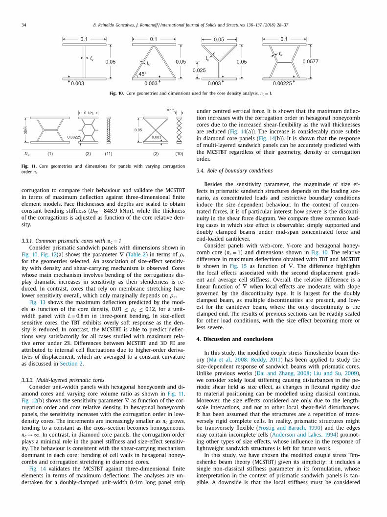
Fig. 10. Core geometries and dimensions used for the core density analysis, n c = 1.
Fig. 11. Core geometries and dimensions for panels with varying corrugation
order n c .
u
t
c
a
i
o
t
o
3
f
n
i
t
n
i
d
e
c
d
i
t
e
l
g
c
e
c
f
l
4
o
s
U
w
r
t
M
s
I
v
b
m
i
l
o
s
i
g
corrugation to compare their behaviour and validate the MCSTBT
in terms of maximum deflection against three-dimensional finite
element models. Face thicknesses and depths are scaled to obtain
constant bending stiffness ( D xx = 848.9 kNm), while the thickness
of the corrugations is adjusted as function of the core relative den-
sity.
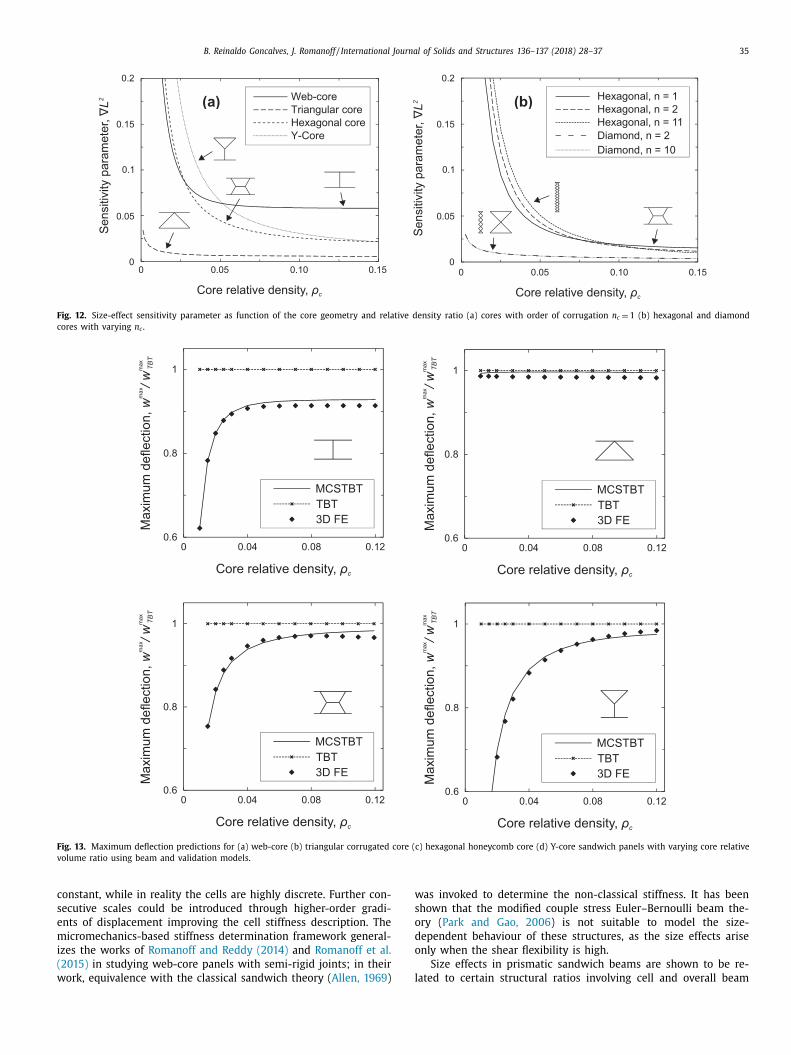
3.3.1. Common prismatic cores with n c = 1
Consider prismatic sandwich panels with dimensions shown in
Fig. 10 . Fig. 12 (a) shows the parameter ∇ ( Table 2 ) in terms of ρc
for the geometries selected. An association of size-effect sensitiv-
ity with density and shear-carrying mechanism is observed. Cores
whose main mechanism involves bending of the corrugations dis-
play dramatic increases in sensitivity as their slenderness is re-
duced. In contrast, cores that rely on membrane stretching have
lower sensitivity overall, which only marginally depends on ρc .
Fig. 13 shows the maximum deflection predicted by the mod-
els as function of the core density, 0.01 ≤ ρc ≤ 0.12, for a unit-
width panel with L = 0.8 m in three-point bending. In size-effect
sensitive cores, the TBT exhibits overly soft response as the den-
sity is reduced. In contrast, the MCSTBT is able to predict deflec-
tions very satisfactorily for all cases studied with maximum rela-
tive error under 2%. Differences between MCSTBT and 3D FE are
attributed to internal cell fluctuations due to higher-order deriva-
tives of displacement, which are averaged to a constant curvature
as discussed in Section 2 .
3.3.2. Multi-layered prismatic cores
Consider unit-width panels with hexagonal honeycomb and di-
amond cores and varying core volume ratio as shown in Fig. 11 .
Fig. 12 (b) shows the sensitivity parameter ∇ as function of the cor-
rugation order and core relative density. In hexagonal honeycomb
panels, the sensitivity increases with the corrugation order in low-
density cores. The increments are increasingly smaller as n c grows,
tending to a constant as the cross-section becomes homogeneous,
n c → ∞ . In contrast, in diamond core panels, the corrugation order
plays a minimal role in the panel stiffness and size-effect sensitiv-
ity. The behaviour is consistent with the shear-carrying mechanism
dominant in each core: bending of cell walls in hexagonal honey-
combs and corrugation stretching in diamond cores.
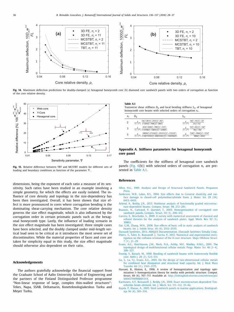
Fig. 14 validates the MCSTBT against three-dimensional finite
elements in terms of maximum deflections. The analyses are un-
dertaken for a doubly-clamped unit-width 0.4 m long panel strip
nder centred vertical force. It is shown that the maximum deflec-
ion increases with the corrugation order in hexagonal honeycomb
ores due to the increased shear-flexibility as the wall thicknesses
re reduced ( Fig. 14 (a)). The increase is considerably more subtle
n diamond core panels ( Fig. 14 (b)). It is shown that the response
f multi-layered sandwich panels can be accurately predicted with
he MCSTBT regardless of their geometry, density or corrugation
rder.
.4. Role of boundary conditions
Besides the sensitivity parameter, the magnitude of size ef-
ects in prismatic sandwich structures depends on the loading sce-
ario, as concentrated loads and restrictive boundary conditions
nduce the size-dependent behaviour. In the context of concen-
rated forces, it is of particular interest how severe is the disconti-
uity in the shear force diagram. We compare three common load-
ng cases in which size effect is observable: simply supported and
oubly clamped beams under mid-span concentrated force and
nd-loaded cantilever.
Consider panels with web-core, Y-core and hexagonal honey-
omb core ( n c = 1) and dimensions shown in Fig. 10 . The relative
ifference in maximum deflections obtained with TBT and MCSTBT
s shown in Fig. 15 as function of ∇ . The difference highlights
he local effects associated with the second displacement gradi-
nt and average cell stiffness. Overall, the relative difference is a
inear function of ∇ when local effects are moderate, with slope
overned by the discontinuity type. It is largest for the doubly
lamped beam, as multiple discontinuities are present, and low-
st for the cantilever beam, where the only discontinuity is the
lamped end. The results of previous sections can be readily scaled
or other load conditions, with the size effect becoming more or
ess severe.
. Discussion and conclusions
In this study, the modified couple stress Timoshenko beam the-
ry ( Ma et al., 2008; Reddy, 2011 ) has been applied to study the
ize-dependent response of sandwich beams with prismatic cores.
nlike previous works ( Dai and Zhang, 2008; Liu and Su, 2009 ),
e consider solely local stiffening causing disturbances in the pe-
iodic shear field as size effect, as changes in flexural rigidity due
o material positioning can be modelled using classical continua.
oreover, the size effects considered are only due to the length-
cale interactions, and not to other local shear-field disturbances.
t has been assumed that the structures are a repetition of trans-
ersely rigid complete cells. In reality, prismatic structures might
e transversely flexible ( Frostig and Baruch, 1990 ) and the edges
ay contain incomplete cells ( Anderson and Lakes, 1994 ) promot-
ng other types of size effects, whose influence in the response of
ightweight sandwich structures is left for future work.
In this study, we have chosen the modified couple stress Tim-
shenko beam theory (MCSTBT) given its simplicity; it includes a
ingle non-classical stiffness parameter in its formulation, whose
nterpretation in the context of prismatic sandwich panels is tan-
ible. A downside is that the local stiffness must be considered
B. Reinaldo Goncalves, J. Romanoff / International Journal of Solids and Structures 136–137 (2018) 28–37 35
Fig. 12. Size-effect sensitivity parameter as function of the core geometry and relative density ratio (a) cores with order of corrugation n c = 1 (b) hexagonal and diamond
cores with varying n c .
Fig. 13. Maximum deflection predictions for (a) web-core (b) triangular corrugated core (c) hexagonal honeycomb core (d) Y-core sandwich panels with varying core relative
volume ratio using beam and validation models.
c
s
e
m
i
(
w
w
s
o
d
o
l
onstant, while in reality the cells are highly discrete. Further con-
ecutive scales could be introduced through higher-order gradi-
nts of displacement improving the cell stiffness description. The
icromechanics-based stiffness determination framework general-
zes the works of Romanoff and Reddy (2014) and Romanoff et al.
2015) in studying web-core panels with semi-rigid joints; in their
ork, equivalence with the classical sandwich theory ( Allen, 1969 )
as invoked to determine the non-classical stiffness. It has been
hown that the modified couple stress Euler–Bernoulli beam the-
ry ( Park and Gao, 2006 ) is not suitable to model the size-
ependent behaviour of these structures, as the size effects arise
nly when the shear flexibility is high.
Size effects in prismatic sandwich beams are shown to be re-
ated to certain structural ratios involving cell and overall beam
36 B. Reinaldo Goncalves, J. Romanoff / International Journal of Solids and Structures 136–137 (2018) 28–37
Fig. 14. Maximum deflection predictions for doubly-clamped (a) hexagonal honeycomb core (b) diamond core sandwich panels with two orders of corrugation as function
of the core relative density.
Fig. 15. Relative difference between TBT and MCSTBT models for different sets of
loading and boundary conditions as function of the parameter ∇ .
Table A.1
Transverse shear stiffness D Q and local bending stiffness S xy of hexagonal
honeycomb core beams with selected orders of corrugation n c .
n c D Q S xy
2 E ( 1 −υ2 )
54 t 3 c ( 281 t 6 f +255 t 3
f t 3 c +8 t 6 c )
s 2 ( 693 t 6 f +708 t 3
f t 3 c +88 t 6 c )
E ( 1 −υ2 )
14 t 6 f +15 t 3
f t 3 c +2 t 6 c
21 t 3 f +5 t 3 c
3 E ( 1 −υ2 )
432 t 3 c ( 668 t 6 f +788 t 3
f t 3 c +31 t 6 c )
s 2 ( 9398 t 6 f +11801 t 3
f t 3 c +1200 t 6 c )
E ( 1 −υ2 )
52 t 6 f +82 t 3
f t 3 c +14 t 6 c
78 t 3 f +19 t 3 c
5 E ( 1 −υ2 )
10800 t 3 c ( 273242 t 6 f +391311 t 3
f t 3 c +17223 t 6 c )
s 2 ( 60753591 t 6 f +89833161 t 3
f t 3 c +7281992 t 6 c )
E ( 1 −υ2 )
724 t 6 f +1866 t 3
f t 3 c +372 t 6 c
1086 t 3 f +265 t 3 c
A
c
p
s
R
A
A
A
B
C
D
E
F
G
H
dimensions, being the exponent of each ratio a measure of its sen-
sitivity. Such ratios have been studied in an example involving a
simple geometry, for which the effects are easily isolated. The in-
fluence of core density and topology in the size-dependency has
been then investigated. Overall, it has been shown that size ef-
fect is more pronounced in cores where corrugation bending is the
dominating shear-carrying mechanism. The core relative density
governs the size effect magnitude, which is also influenced by the
corrugation order in certain prismatic panels such as the hexag-
onal honeycomb type. Lastly, the influence of loading scenario in
the size effect magnitude has been investigated; three simple cases
have been selected, and the doubly clamped under mid-length ver-
tical load seen to be critical as it introduces the most severe set of
discontinuities. While the material properties of faces and core are
taken for simplicity equal in this study, the size effect magnitude
should otherwise also dependent on their ratio.
Acknowledgements
The authors gratefully acknowledge the financial support from
the Graduate School of Aalto University School of Engineering and
the partners of the Finland Distinguished Professor programme
“Non-linear response of large, complex thin-walled structures”:
Tekes, Napa, SSAB, Deltamarin, Koneteknologiakeskus Turku and
Meyer Turku.
ppendix A. Stiffness parameters for hexagonal honeycomb
ore panel
The coefficients for the stiffness of hexagonal core sandwich
anels ( Fig. 6 (b)) with selected orders of corrugation n c are pre-
ented in Table A.1 .
eferences
llen, H.G. , 1969. Analysis and Design of Structural Sandwich Panels. Pergamon
Press . nderson, W.B. , Lakes, R.S. , 1994. Size effects due to Cosserat elasticity and sur-
face damage in closed-cell polymethacrylimide foam. J. Mater. Sci. 29 (24),6413–6419 .
rbind, A. , Reddy, J.N. , 2013. Nonlinear analysis of functionally graded microstruc-
ture-dependent beams. Compos. Struct. 98, 272–281 . uannic, N. , Cartraud, P. , Quesnel, T. , 2003. Homogenization of corrugated core
sandwich panels. Compos. Struct. 59 (3), 299–312 . arrera, E. , Brischetto, S. , 2009. A survey with numerical assessment of classical and
refined theories for the analysis of sandwich plates. Appl. Mech. Rev. 62 (1),10803 .
ai, G.M. , Zhang, W.H. , 2008. Size effects of basic cell in static analysis of sandwich
beams. Int. J. Solids Struc. 45 (9), 2512–2533 . Dassault Systèmes, 2013. ABAQUS Documentation. (Dassault Systèmes Simulia Corp. .
hlers, S. , Tabri, K. , Romanoff, J. , Varsta, P. , 2012. Numerical and experimental inves-tigation on the collision resistance of the X-core structure. Ships Offshore Struct.
7 (1), 21–29 . Evans, A.G. , Hutchinson, J.W. , Fleck, N.A. , Ashby, M.F. , Wadley, H.N.G. , 2001. The
topological design of multifunctional cellular metals. Progr. Mater. Sci. 46 (3–4),
309–327 . rostig, Y. , Baruch, M. , 1990. Bending of sandwich beams with transversely flexible
core. AIAA J. 28 (3), 523–531 . u, S. , Lu, T.J. , Evans, A.G. , 2001. On the design of two-dimensional cellular metals
for combined heat dissipation and structural load capacity. Int. J. Heat MassTransfer 44 (11), 2163–2175 .
assani, B., Hinton, E., 1998. A review of homogenization and topology opti-mization I—homogenization theory for media with periodic structure. Comput.
Struct. 69 (6), 707–717. Available at: http://linkinghub.elsevier.com/retrieve/pii/
S004579499800131X . Karttunen, A.T. , Romanoff, J. , Reddy, J.N. , 2016. Exact microstructure-dependent Tim-
oshenko beam element. Int. J. Mech. Sci. 111–112, 35–42 . Kujala, P. , Klanac, A. , 2005. Steel sandwich panels in marine applications. Brodograd-
nja 56 (4), 305–314 .
B. Reinaldo Goncalves, J. Romanoff / International Journal of Solids and Structures 136–137 (2018) 28–37 37
L
L
M
N
P
R
R
R
R
S
V
Y
Z
iu, S. , Su, W. , 2009. Effective couple-stress continuum model of cellular solids andsize effects analysis. Int. J. Solids Struct. 46 (14–15), 2787–2799 .
ok, T.S. , Cheng, Q.H. , 20 0 0. Elastic stiffness properties and behavior of truss-coresandwich panel. J. Struct. Eng. 126 (5), 552–559 .
a, H.M. , Gao, X.L. , Reddy, J.N. , 2008. A microstructure-dependent Timoshenkobeam model based on a modified couple stress theory. J. Mech. Phys. Solids
56 (12), 3379–3391 . aar, H. , Kujala, P. , Simonsen, B.C. , Ludolphy, H. , 2002. Comparison of the crashwor-
thiness of various bottom and side structures. Marine Struct. 15 (4–5), 443–460 .
ark, S.K., Gao, X.-L., 2006. Bernoulli–Euler beam model based on a modi-fied couple stress theory. J. Micromech. Microeng. 16 (11), 2355–2359.
Available at: http://stacks.iop.org/0960-1317/16/i=11/a=015?key=crossref. 5e13d8eb3f8bcf03dc33ffeb6bd15219 .
eddy, J.N., 2011. Microstructure-dependent couple stress theories of functionallygraded beams. J. Mech. Phys. Solids 59 (11), 2382–2399. Available at: http://
linkinghub.elsevier.com/retrieve/pii/S0 0225096110 01566 .
einaldo Goncalves, B. , Karttunen, A. , Romanoff, J. , Reddy, J.N. , 2017. Buckling andfree vibration of shear-flexible sandwich beams using a couple-stress-based fi-
nite element. Compos. Struct. 165, 233–241 .
omanoff, J., Reddy, J.N., 2014. Experimental validation of the modified cou-ple stress Timoshenko beam theory for web-core sandwich panels. Com-
pos. Struct. 111, 130–137. Available at: http://linkinghub.elsevier.com/retrieve/pii/S026382231300620X .
omanoff, J., Reddy, J.N., Jelovica, J., 2015. Using non-local timoshenko beamtheories for prediction of micro- and macro-structural responses. Com-
pos. Struct.. Available at: http://www.sciencedirect.com/science/article/pii/ S0263822315005528 .
un, C.T. , Vaidya, R.S. , 1996. Prediction of composite properties from a representa-
tive volume element. Compos. Sci. Technol. 56 (2), 171–179 . aldevit, L. , Hutchinson, J.W. , Evans, A.G. , 2004. Structurally optimized sandwich
panels with prismatic cores. Int. J. Solids Struct. 41 (18–19), 5105–5124 . ang, F. , Chong, A.C.M. , Lam, D.C.C. , Tong, P. , 2002. Couple stress based strain gradi-
ent theory for elasticity. Int. J. Solids Struct. 39 (10), 2731–2743 . enkert, D. , 1995. An Introduction to Sandwich Construction. Engineering Materials
Advisory Service, Sheffield, UK .


![openresearch.lsbu.ac.uk · Web viewMoreover, Wu et al. [13] investigated free vibration and elastic buckling of sandwich beams with a stiff core and functionally graded carbon nanotube](https://img.pdfslide.us/doc/110x75/5ea378d753a10e0852431960/web-view-moreover-wu-et-al-13-investigated-free-vibration-and-elastic-buckling.jpg)