Embed Size (px)
Citation preview
1
The Physical Layer
Chapter 2
2
The Theoretical Basis for Data
Communication
• Fourier Analysis
• Bandwidth-Limited Signals
• Maximum Data Rate of a Channel

3
Reminder:
Any (reasonably behaved) periodic signal g(t), of period T, can be
constructed by summing a (possibly infinite) number of sines and
cosines (called a Fourier series):
where
f = 1/T is the fundamental frequency
an and bn are the sine and cosine amplitudes of the nth
harmonics
(For nonperiodic signals, refer to Fourier transforms, but the intuition is
the same)
Fourier Series Decomposition
1)-(2 )2cos()2sin(2
1)(
11
nftbnftac tg
n
n
n
n
2( ) s in ( 2 )
2( ) c o s ( 2 )
2( )
n
n
a g t n f t d t
b g t n f t d t
c g t d t

4
Fourier Transform

5
We refer to |G(f)| as the magnitude spectrum of the signal g(t), and
refer to arg {G(f)} as its phase spectrum.
Fourier Transform (2)

6
Bandwidth-Limited Signals
A binary signal and its root-mean-square Fourier amplitudes.
(b) – (c) Successive approximations to the original signal.

7
Bandwidth-Limited Signals (2)
(d) – (e) Successive approximations to the original signal.

8
Bandwidth-Limited Signals (3)
Relation between data rate and harmonics.
Suppose we transmit the previous binary signal (of 8 bits) infinitely often,
we have a periodic signal.
Suppose the transmission is done on a telephone line (cut-off frequency = ± 3000 Hz)
Data rate= D T = 8/D f = 1/T greatest int ≤ 3000 × T
OK
Not
OK

9
Sample function of random binary wave

10
Autocorrelation function of random binary wave
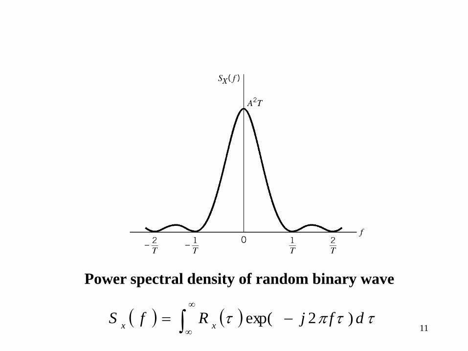
11
Power spectral density of random binary wave
dfjRfSxx
)2exp(

12
Line codes for the electrical representations of binary data.
(a) Unipolar NRZ signaling. (b) Polar NRZ signaling. (c) Unipolar RZ signaling.
(d) Bipolar RZ signaling. (e) Split-phase or Manchester code.
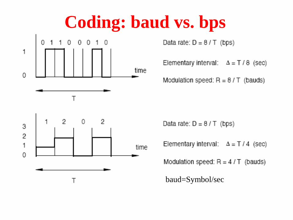
baud=Symbol/sec
Coding: baud vs. bps

14
Nyquist’s Theorem
Max. data rate =
(Noiseless Channel)
where V represent No. of discrete level of signals.
Shannon’s Theorem
Max. data rate =
(Noisy Channel)
where S/N represent signal-to-noise ratio.
bits/sec log22
VH
bits/sec )1(log2
N
SH
Maximum Data Rate of a Channel

15
Guided Transmission Media
• Magnetic Media
• Twisted Pairs
• Coaxial Cable
• Power Lines
• Fiber Optics

16
Magnetic Media
• Write data onto magnetic media
• Disks
• Tapes
• Data transmission speed
• Never underestimate the bandwidth of a station
wagon full of tapes hurtling down the highway.
17
Twisted Pair Twisted pair
– two insulated copper wires, 1mm thick
– to reduce electrical interference from similar pairs close by
– low cost
Application
– telephone system: nearly all telephones
– several km without amplification
Bandwidth
– thickness of the wire, and distance
– Typically, several Mbps for a few km

18
(a) Category 3 Unshielded Twisted Pair (UTP). BW.=16MHz
(b) Category 5 Unshielded Twisted Pair (UTP). BW.=100MHz
(c) Cat. 6 BW.=250MHz, Cat.7 BW.= 600MHz
Twisted Pairs
Category 5 UTP cable with four twisted pairs
19
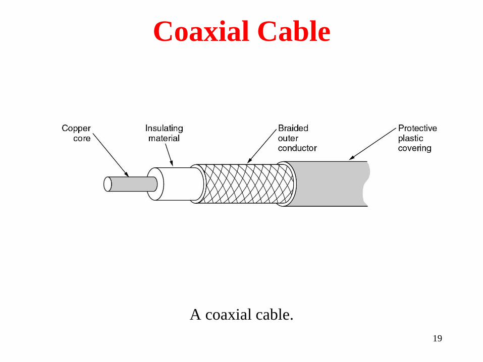
Coaxial Cable
A coaxial cable.

Power Lines
A network that uses household electrical wiring.
Computer Networks, Fifth Edition by Andrew Tanenbaum and David Wetherall, © Pearson Education-Prentice Hall, 2011
21
Baseband Coaxial Cable Coaxial cable (coax)
– better shielding (Fig. 2-4)
– longer distances at higher speeds
– two kinds
• 50-ohm cable: digital transmission
• 75-ohm cable: analog transmission (Cable TV)
Bandwidth
– 1-km cable: 1-2 Gbps
Application
– telephones system: coaxial cable are being replaced by fiber optics
– widely used for cable TV

22
Broadband Coaxial Cable Broadband cable
– any cable network using analog transmission
– 300 MHz (1bps ~ 1 Hz of bandwidth)
– 100 km
– multiple channels: 6-MHz channels
Difference between baseband and broadband – broadband covers a large area
– analog amplifiers are needed
Broadband cable
– inferior to baseband (single channel) for sending digital data
– advantage: a huge amount is installed
– In US, TV cable more than 80% of all homes
– cable TV systems will operate as MANs and offer telephone and
other service

23
fiber

24
Fiber Optics
Achievable bandwidth with fiber: more than 50,000 Gbps
– 40 Gbps/wavelength : due to inability to convert electrical ->
optical signals faster
– 100 Gbps: in lab
CPUs’ physical limits
– speed of electron
– heat dissipation
Communication (100 times/decade) won the race with
computation (10 times/decade)
– use network, and avoid computations at all
25
Fiber Optics (2) Optical Transmission Systems
– light source
– transmission medium: ultra-thin fiber of glass
– detector: light -> electrical pulse
Refraction ( See Fig. 2.5)
Multimode fiber
– many different rays are bounced at different angles
Single-mode fiber
– fiber’s diameter: a few wavelengths of light
– for longer distances
– lasers: 100 km without repeaters

26
Fiber Optics (3)
(a) Three examples of a light ray from inside a silica fiber impinging
on the air/silica boundary at different angles.
(b) Light trapped by total internal reflection.
Snell’s
(total internal reflection)

27
Transmission of Light through Fiber
Attenuation of light through fiber in the infrared region.

28
Fiber Cables
(a) Side view of a single fiber.
(b) End view of a sheath with three fibers.

29
Fiber Cables (2)
A comparison of semiconductor diodes and LEDs as light sources.
Long

30
Comparison Between Fiber Optics and
Copper Wire Fiber Optics
– Much higher bandwidths
– Low attenuation: amplifiers for every 30 km
– Not affected by power surges, electromagnetic interference, power
failures, corrosive chemicals
– Telephone systems like it: thin and lightweight
• copper has excellent resale value
• fiber has much lower installation cost
– Quite difficult to tap: do not leak light
– Disadvantage
• two-way communication: two fibers or two frequency bands on one
fiber
• fiber interfaces are more expensive than electrical interfaces
Copper Wire
– Amplifiers : ~ every 5 km

31
Wireless Transmission
• The Electromagnetic Spectrum
• Radio Transmission
• Microwave Transmission
• Infrared and Millimeter Waves
• Lightwave Transmission

32
Electromagnetic Spectrum lf = c,
– c: 3 * 108 m/sec
– copper or fiber: 2/3 speeds
Can be used for transmitting information
– radio, microwave, infrared, and visible light
– by modulating the amplitude, frequency, or phase of the waves
The others
– Ultraviolet light, X-rays, and gamma rays
– they are better due to their higher frequencies
– disadvantages
• hard to produce
• hard to modulate
• do not propagate well through buildings
• dangerous to living things
National and International agreements about who can use
which frequencies.
3)-(2 22
l
l
ll
cf
c
d
df

33
Electromagnetic Spectrum (1)
The electromagnetic spectrum and its uses for communication.
34
Radio Transmission
Radio waves
– easy to generate
– travel long distances
– penetrate buildings easily (< 2.0GHz)
– omnidirectional (travel in all directions)
Properties
– at low frequencies
• pass through obstacles well
• power falls off sharply with distance ( 1 / r^3 in air)
– at high frequencies
• tend to travel in straight lines
• bounce off obstacles
• absorbed by rain
– subject to interference from motors and electrical equipment

35
Radio Transmission (2)
VLF, LF, and MF Bands (See Fig. 2-12a)
– radio waves follow the ground
– can be detected for 1000 km at the lower frequencies
– offer relatively low bandwidth
HF and VHF Bands
– the waves reaching the ionoshpere (電離層) are
refracted back to the earth
– Hams (amateur radio operators) use them to talk long
distances

The Electromagnetic Spectrum (2)
Spread spectrum and ultra-wideband
(UWB) communication
Computer Networks, Fifth Edition by Andrew Tanenbaum and David Wetherall, © Pearson Education-Prentice Hall, 2011

37
Radio Transmission (3)
(a) In the VLF, LF, and MF bands, radio waves follow the
curvature of the earth.
(b) In the HF band, they bounce off the ionosphere.

38
Microwave Transmission
Microwaves
– above 100 Mhz
– travel in straight lines, narrowly focused
– long distance telephone transmission systems (before fiber optics)
– MCI: Microwave Communications, Inc. (A company was
competing with AT&T)
– repeaters needed periodically
– do not penetrate buildings well
– Multipath fading: some divergence, some refracted
– problem at 4 GHz: absorption by water (rain)
Usage
– widely used by long-distance telephone, cellular telephones, TV
Advantages over Fiber Optics
– do not need right of way: microwave tower for every 50 km (MCI)
– relatively inexpensive (towers and antennas)

39
Microwave Transmission (2) Industrial/Scientific/Medical Bands (ISM)
– do not require government licensing
– cordless telephones, garage door openers, wireless hi-fi
speakers, security gates
– higher bands
• more expensive electronics
• interference from microwave and radar installations
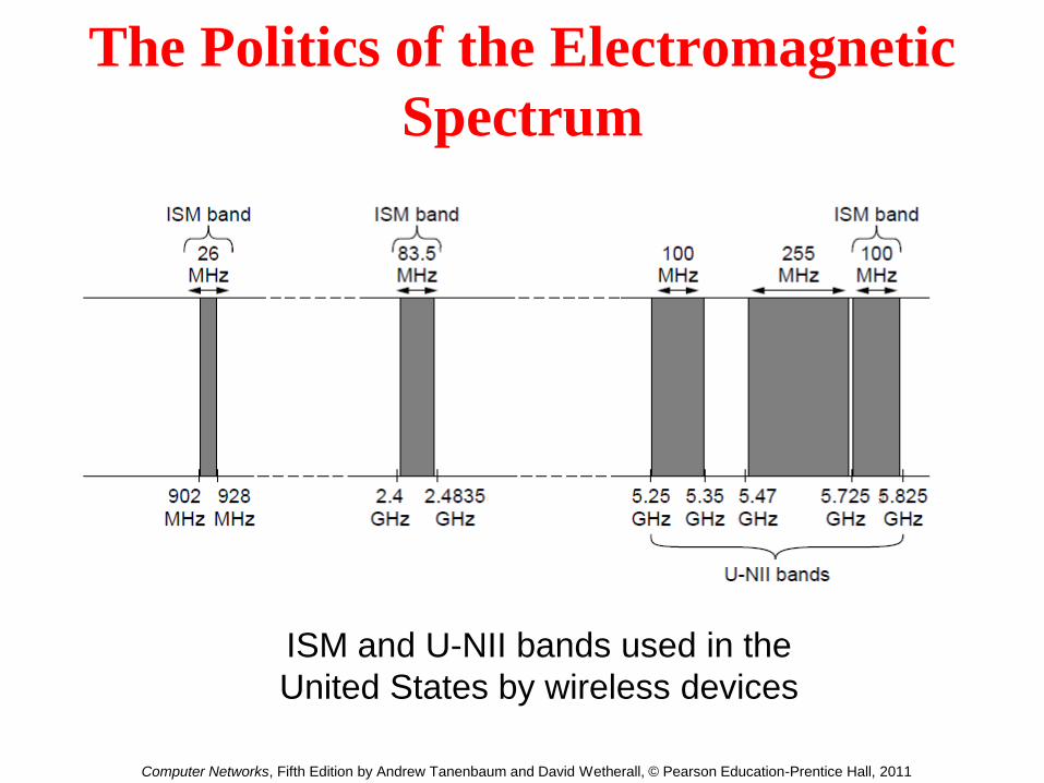
The Politics of the Electromagnetic
Spectrum
ISM and U-NII bands used in the
United States by wireless devices
Computer Networks, Fifth Edition by Andrew Tanenbaum and David Wetherall, © Pearson Education-Prentice Hall, 2011

41
Infrared and Millimeter Waves
short range communications:
– remote controllers for TVs, VCRs, and stereos
relatively directional, cheap, easy to build
do not pass through solid objects
– no interference between rooms
– security is better than radio systems
– no government license is needed
Indoor wireless LAN

42
Lightwave Transmission
Unguided optical signaling
– to connect LANs in two buildings via lasers mounted on rooftops
• very high bandwidth
• very low cost
• Relatively easy to install
• does not require FCC license
• need to aim accurately
• disadvantage: laser beams cannot penetrate rain or thick fog
An example interference with convection currents
– See Fig. 2-14
43
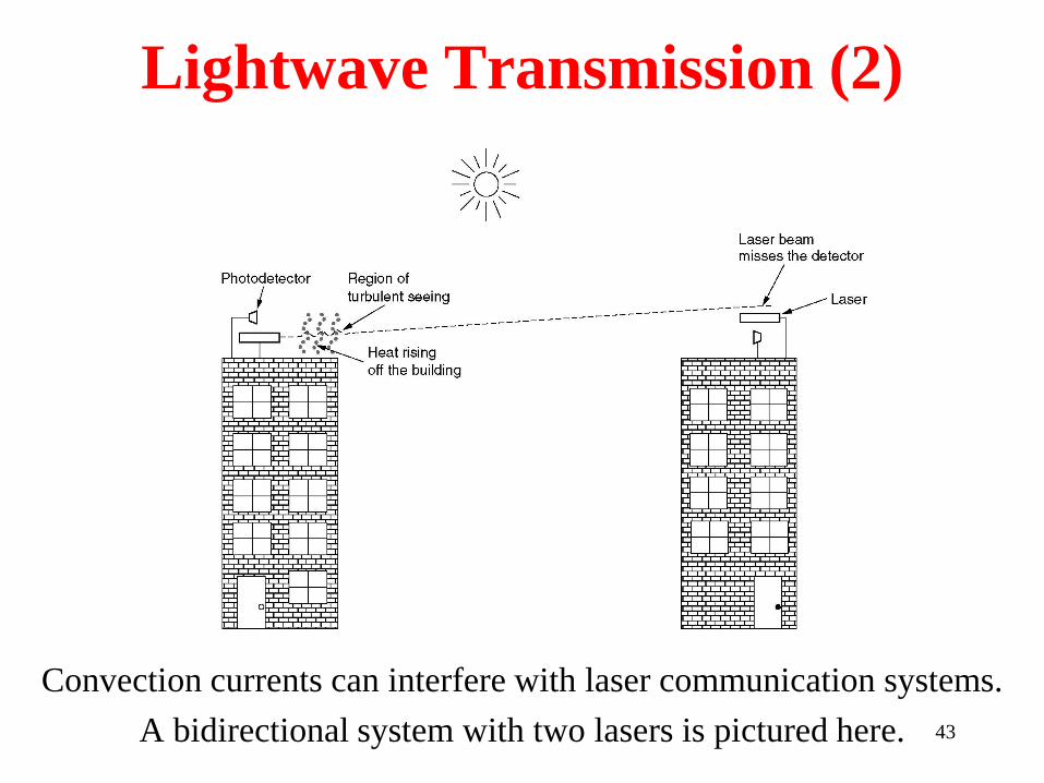
Lightwave Transmission (2)
Convection currents can interfere with laser communication systems.
A bidirectional system with two lasers is pictured here.
44
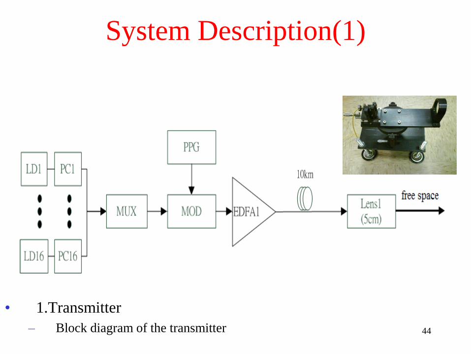
System Description(1)
• 1.Transmitter
– Block diagram of the transmitter
Broadband Communication Laboratory
45
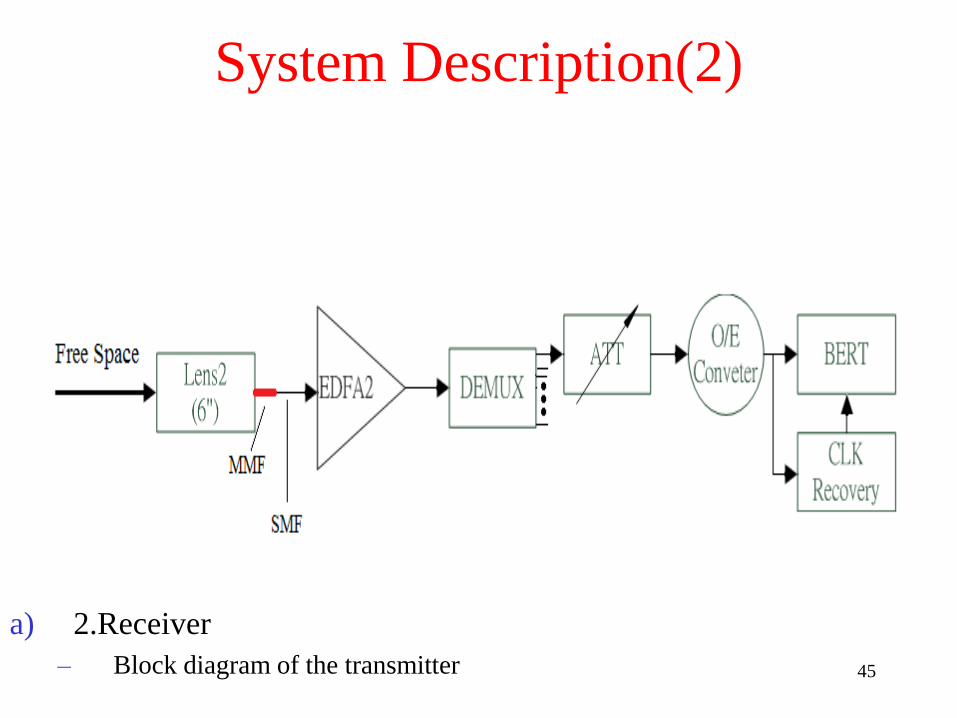
System Description(2)
a) 2.Receiver
– Block diagram of the transmitter
Broadband Communication Laboratory
46
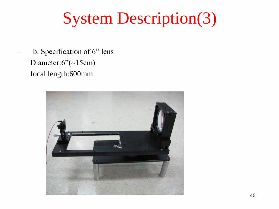
– b. Specification of 6” lens
Diameter:6”(~15cm)
focal length:600mm
System Description(3)
Broadband Communication Laboratory

47
• Tx in Lulin astronomical observatory
• Rx in Dong-Pu
• Wavelength:1537.37~1549.36nm
Experiment Set-up
Broadband Communication Laboratory

– BER versus Received Power
48
Measurement Results
Broadband Communication Laboratory

49
Communication Satellites
• Geostationary Satellites
• Medium-Earth Orbit Satellites
• Low-Earth Orbit Satellites
• Satellites versus Fiber

50
Communication Satellites
Communication satellites and some of their properties,
including altitude above the earth, round-trip delay time
and number of satellites needed for global coverage.

51
Communication Satellites (2)
The principal satellite bands.

52
Communication Satellites (3)
VSATs using a hub.

Low-Earth Orbit Satellites (1)
The Iridium satellites form six necklaces
around the earth.
Computer Networks, Fifth Edition by Andrew Tanenbaum and David Wetherall, © Pearson Education-Prentice Hall, 2011

54
Globalstar
(a) Relaying in space.
(b) Relaying on the ground.

Digital Modulation and Multiplexing
• Baseband Transmission
• Passband Transmission
• Frequency Division Multiplexing
• Time Division Multiplexing
• Code Division Multiplexing
Computer Networks, Fifth Edition by Andrew Tanenbaum and David Wetherall, © Pearson Education-Prentice Hall, 2011

Baseband Transmission
Line codes: (a) Bits, (b) NRZ, (c) NRZI,
(d) Manchester, (e) Bipolar or AMI.
Computer Networks, Fifth Edition by Andrew Tanenbaum and David Wetherall, © Pearson Education-Prentice Hall, 2011

Clock Recovery
4B/5B mapping.
Computer Networks, Fifth Edition by Andrew Tanenbaum and David Wetherall, © Pearson Education-Prentice Hall, 2011

Passband Transmission (1)
(a) A binary signal. (b) Amplitude shift keying.
(c) Frequency shift keying. (d) Phase shift keying.
Computer Networks, Fifth Edition by Andrew Tanenbaum and David Wetherall, © Pearson Education-Prentice Hall, 2011

Passband Transmission (2)
(a) QPSK. (b) QAM-16. (c) QAM-64.
Computer Networks, Fifth Edition by Andrew Tanenbaum and David Wetherall, © Pearson Education-Prentice Hall, 2011

Frequency Division Multiplexing (1)
Gray-coded QAM-16.
Computer Networks, Fifth Edition by Andrew Tanenbaum and David Wetherall, © Pearson Education-Prentice Hall, 2011
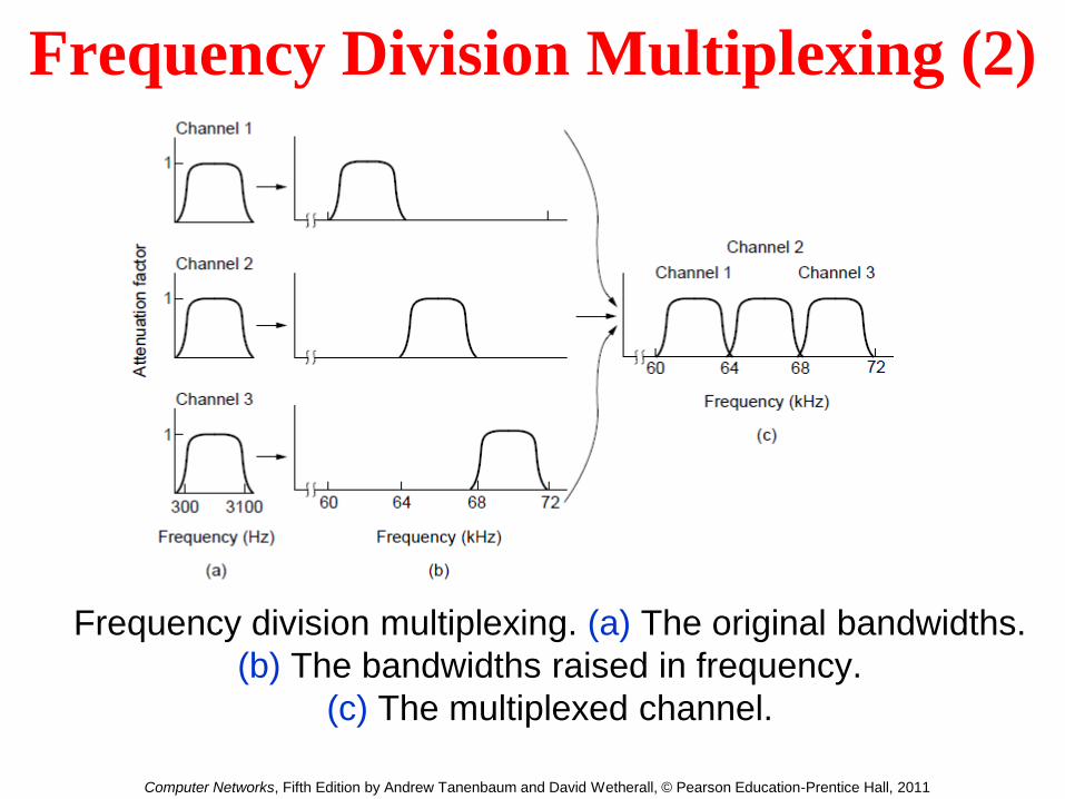
Frequency Division Multiplexing (2)
Frequency division multiplexing. (a) The original bandwidths.
(b) The bandwidths raised in frequency.
(c) The multiplexed channel.
Computer Networks, Fifth Edition by Andrew Tanenbaum and David Wetherall, © Pearson Education-Prentice Hall, 2011

Frequency Division Multiplexing (3)
Orthogonal frequency division
multiplexing (OFDM).
Computer Networks, Fifth Edition by Andrew Tanenbaum and David Wetherall, © Pearson Education-Prentice Hall, 2011

Time Division Multiplexing
Time Division Multiplexing (TDM).
Computer Networks, Fifth Edition by Andrew Tanenbaum and David Wetherall, © Pearson Education-Prentice Hall, 2011

Code Division Multiplexing (1)
(a) Chip sequences for four stations.
(b) Signals the sequences represent
Computer Networks, Fifth Edition by Andrew Tanenbaum and David Wetherall, © Pearson Education-Prentice Hall, 2011

Code Division Multiplexing (2)
(a) Six examples of transmissions.
(b) Recovery of station C’s
Computer Networks, Fifth Edition by Andrew Tanenbaum and David Wetherall, © Pearson Education-Prentice Hall, 2011
66
Public Switched Telephone System
• Structure of the Telephone System
• The Politics of Telephones
• The Local Loop: Modems, ADSL and Wireless
• Trunks and Multiplexing
• Switching

67
Telephone System
Telephone system is tightly intertwined with WAN
– cable between two computers
• transfer at memory speeds: 108 bps
• error rate: 10-12 bits (one per day)
– dial up line
• data rate: 104 bps
• error rate: 10-5 bits
• 11 orders of magnitude worse than cable

68
Structure of Telephone System
Hierarchy of telephone system: 5 levels
Terms
– end office (local central office): area code + first 3 digits
– local loop: two copper wires/telephone, < 10 km
– toll office
• tandem office: within the same local area
– switching centers: primary, sectional, and regional exchanges
– See Fig. 2-21
Advantages of digital signaling (-5 & +5 volts)
– lower error rate: less loss for long distance with regenerators
– voice, data, music, and images can be interspersed
– much higher data rates with existing lines
– much cheaper (to distinguish 0 & 1 is easier)
– maintenance is easier: tracking problems

69
Structure of the Telephone System (2)
(a) Fully-interconnected network.
(b) Centralized switch.
(c) Two-level hierarchy.

70
Structure of the Telephone System (3)
A typical circuit route for a medium-distance call.

71
Major Components of the
Telephone System
• Local loops
Analog twisted pairs going to houses and
businesses
• Trunks
Digital fiber optics connecting the switching
offices
• Switching offices
Where calls are moved from one trunk to another

72
The Politics of Telephones
The relationship of Local Access and Transport Areas (LATAs), Local Exchange Carriers (LECs), and
IntereXchange Carriers (IXCs). All the circles are LEC switching offices. Each hexagon belongs to the
IXC whose number is on it.
(point of presence)

73
The Local Loop: Modems,
ADSL, and Wireless
The use of both analog and digital transmissions for a computer to
computer call. Conversion is done by the modems and codecs.

74
Modems Two problems with DC (baseband signaling)
– attenuation: the amount of energy lost depends on the frequency
– delay distortion: different Fourier components travel at different
speeds
Modem
– Stream of bits <--> a modulated carrier
– AC signaling
• Sine wave carrier: a continuous tone in the 1000- to 2000-Hz
• Amplitude, frequency, or phase can be modulated (See Fig. 2-24)
– How to go to higher speeds
• Baud: number of changes per second
• Transmitting more bits per baud (See Figs. 2-25 and 2-26)
• QAM (Quadrature Amplitude Modulation): transmitting 9600 bps using
2400 baud line

75
Digital Subscriber Lines (DSL)
Bandwidth versus distanced over category 3 Unshielded Twisted Pair (UTP) for DSL.
•The DSL uses unfiltered (without coil) local loop lines
•The capacity of local loop depends on length, the thickness, and general quality
When all the other factors (new wires, modest bundles, …) are optimal

76
Digital Subscriber Lines (2)
Operation of Asymmetric DSL (ADSL) using discrete multitone modulation.
•The Discrete MultiTone (DMT) modulation divides the available 1.1 MHz spectrum
on the local loop into 256 independent channels of 4312.5 Hz each
• Channel 0 is used for voice, channels 1~5 are for the guard band
Of the remaining 250 channels, one is used for upstream control, and one is used
for downstream control. The others are for use data.
77
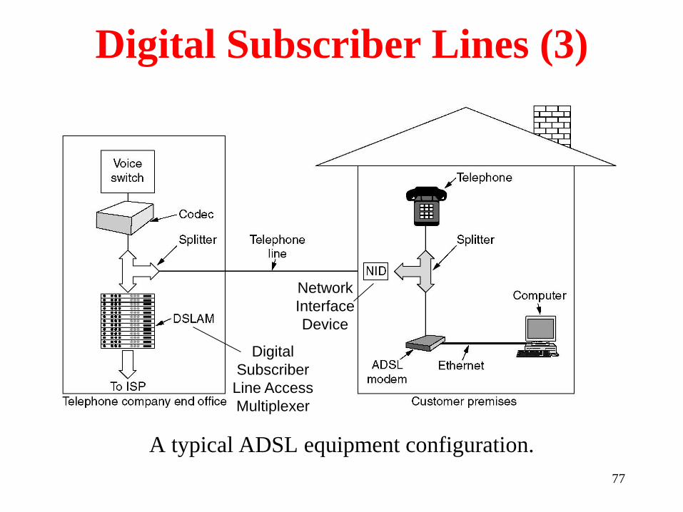
Digital Subscriber Lines (3)
A typical ADSL equipment configuration.
Network
Interface
Device
Digital
Subscriber
Line Access
Multiplexer

78
Wireless Local Loops
Architecture of an Local Multipoint Distribution Service (LMDS) system.
(For Competitive Local Exchange Carrier)
LMDS uses 28 GHz, 38GHz, 58GHz…
Problems of LMDS are high absorption (leaves, rain) and
line of sight needed

Fiber To The Home
Passive optical network for Fiber To The Home.
Computer Networks, Fifth Edition by Andrew Tanenbaum and David Wetherall, © Pearson Education-Prentice Hall, 2011

80
Time Division Multiplexing
The T1 carrier (1.544 Mbps).
Pulse Code Modulation (PCM) is the heart of the modern telephone system
A analog signal is sampled, quantized and coded
Each channel has 8bits, 24 channels and one framing bit form a frame of 125 µsec

81
Time Division Multiplexing (2)
Delta modulation.

82
Time Division Multiplexing (3)
Multiplexing T1 streams into higher carriers.

83
Time Division Multiplexing (4)
Two back-to-back SONET frames.
A basic Synchronous Optical Network (SONET) frame is a block of 810 bytes for 125 µsec
(Synchronous
Payload
Envelope)

SONET/SDH (2)
SONET and SDH multiplex rates.
Computer Networks, Fifth Edition by Andrew Tanenbaum and David Wetherall, © Pearson Education-Prentice Hall, 2011

85
Wavelength Division Multiplexing
Wavelength division multiplexing.
(OR Array Waveguide, AWG)
When the wavelengths are spaced closer, e.g. 0.1 nm,
the system is referred to as Dense WDM (DWDM)
86
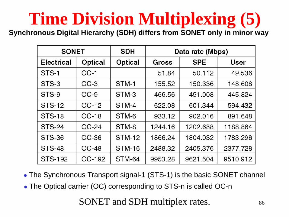
Time Division Multiplexing (5)
SONET and SDH multiplex rates.
The Synchronous Transport signal-1 (STS-1) is the basic SONET channel
The Optical carrier (OC) corresponding to STS-n is called OC-n
Synchronous Digital Hierarchy (SDH) differs from SONET only in minor way
87
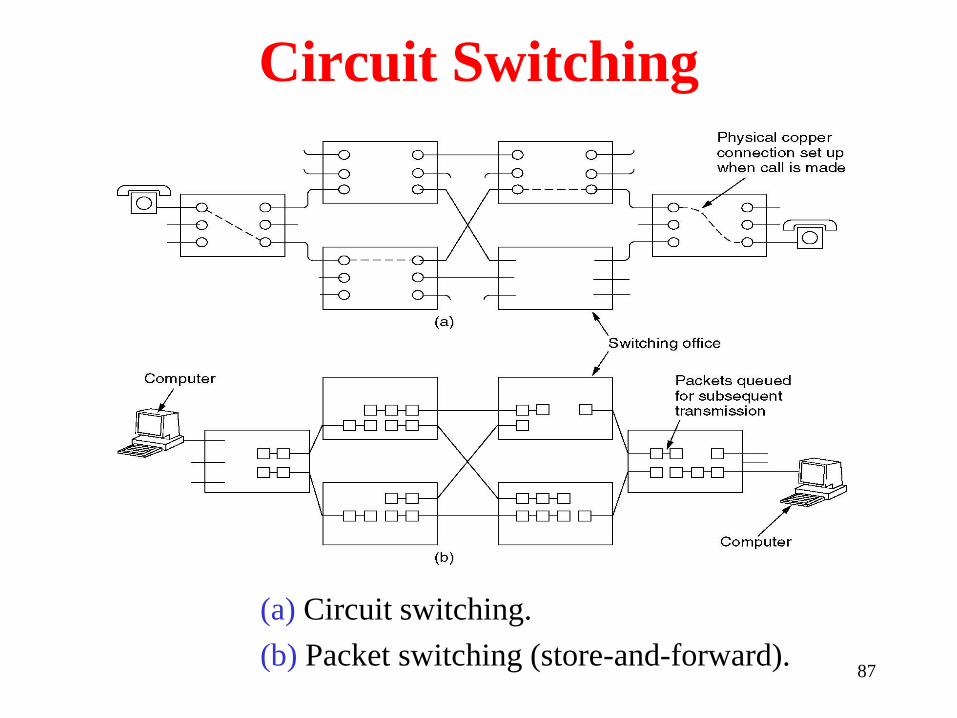
Circuit Switching
(a) Circuit switching.
(b) Packet switching (store-and-forward).

88
Message Switching
(a) Circuit switching (b) Message switching (c) Packet switching

Circuit Switching/Packet Switching (3)
A comparison of circuit-switched and packet-switched networks.
Computer Networks, Fifth Edition by Andrew Tanenbaum and David Wetherall, © Pearson Education-Prentice Hall, 2011

90
The Mobile Telephone System
First-Generation Mobile Phones:
Analog Voice
Second-Generation Mobile Phones:
Digital Voice
Third-Generation Mobile Phones:
Digital Voice, Data, and image
Fourth-Generation Mobile Phones (OFDM):
multimedia
91
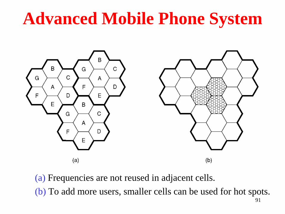
Advanced Mobile Phone System
(a) Frequencies are not reused in adjacent cells.
(b) To add more users, smaller cells can be used for hot spots.

GSM—The Global System for
Mobile Communications (1)
GSM mobile network architecture.
Computer Networks, Fifth Edition by Andrew Tanenbaum and David Wetherall, © Pearson Education-Prentice Hall, 2011

93
GSM
Global System for Mobile
Communicationss
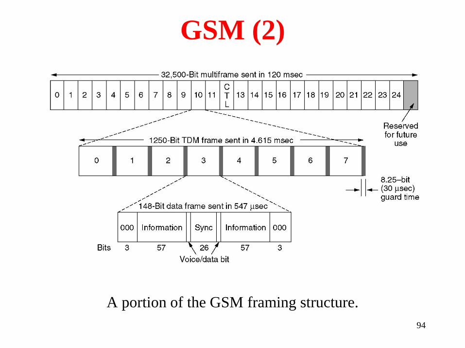
GSM uses 124 frequency channels, each of which
uses an eight-slot TDM system
94
GSM (2)
A portion of the GSM framing structure.

Digital Voice and Data (1)
Basic services intend by IMT-2000 network
a) High-quality voice transmission.
b) Messaging (replacing email, fax, SMS, chat).
c) Multimedia (music, videos, films, television).
d) Internet access (Web surfing, incl. audio, video).
Computer Networks, Fifth Edition by Andrew Tanenbaum and David Wetherall, © Pearson Education-Prentice Hall, 2011

Digital Voice and Data (2)
Soft handoff (a) before, (b) during, and (c) after.
Computer Networks, Fifth Edition by Andrew Tanenbaum and David Wetherall, © Pearson Education-Prentice Hall, 2011

97
Cable Television
Community Antenna Television
Internet over Cable
Spectrum Allocation
Cable Modems
ADSL versus Cable

98
Community Antenna Television
An early cable television system.

99
Internet over Cable
Cable Television

100
Internet over Cable (2)
The fixed telephone system.

101
Spectrum Allocation
Frequency allocation in a typical cable TV system
used for Internet access

102
Cable Modems
Typical details of the upstream and downstream
channels in North America.