Embed Size (px)
Citation preview

8.0.1 Chapter 8 Introduction
• Physical layer
protocols and
services
• Physical layer
signaling and
encoding.
• Role of signals used
to represent bits as a
frame is transported
across the local
media.
• Basic characteristics
of copper, fiber, and
wireless network
media.
• Common uses of
copper, fiber, and
wireless network
media.

8.1.1 Physical Layer Purpose
The delivery of
frames across the
local media
requires the
following Physical
layer elements::
• Physical media
and associated
connectors
• Representation
of bits on the
media
• Encoding of
data and control
information
• Transmitter and
receiver
circuitry on the
network devices

8.1.2 Physical Layer Operation

8.1.3 Physical Layer Standards
• The International
Organization for
Standardization (ISO)
• The Institute of Electrical
and Electronics Engineers
(IEEE)
• The American National
Standards Institute (ANSI)
• The International
Telecommunication Union
(ITU)
• The Electronics Industry
Alliance/Telecommunicatio
ns Industry Association
(EIA/TIA)
• National
telecommunications
authorities such as the
Federal Communication
Commission (FCC) in the
USA.
Internet Engineering Task Force
(IETF) in RFCs.

8.1.3 Physical Signal Standards

8.1.3 Physical Connection Standards

8.1.3 Physical Cable Standards

8.1.4 Physical Layer Principles
Encoding: Converting a stream of data bits into a
predefined code.
Signaling: Electrical, optical, or wireless signals that
represent the "1" and "0" on the media.
8.2.1 Signaling Bits on the Media
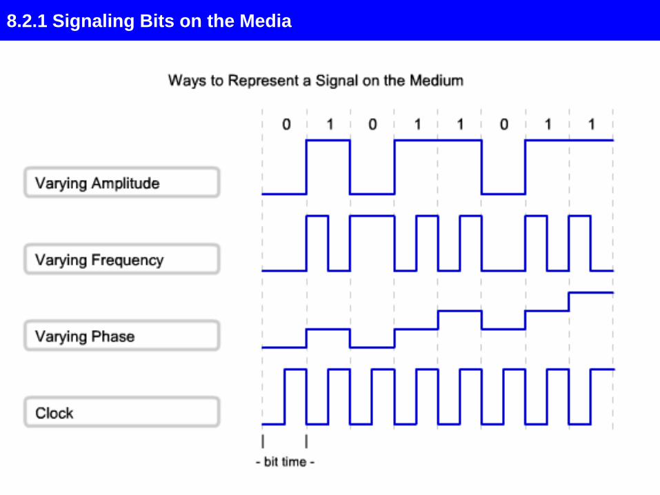
8.2.1 Signaling Bits for the Media

8.2.1 Signaling Bits for the Media
Although Manchester
Encoding is not efficient
enough to be used at higher
signaling speeds, it is the
signaling method employed
by 10BaseT Ethernet
(Ethernet running at 10
Megabits per second).

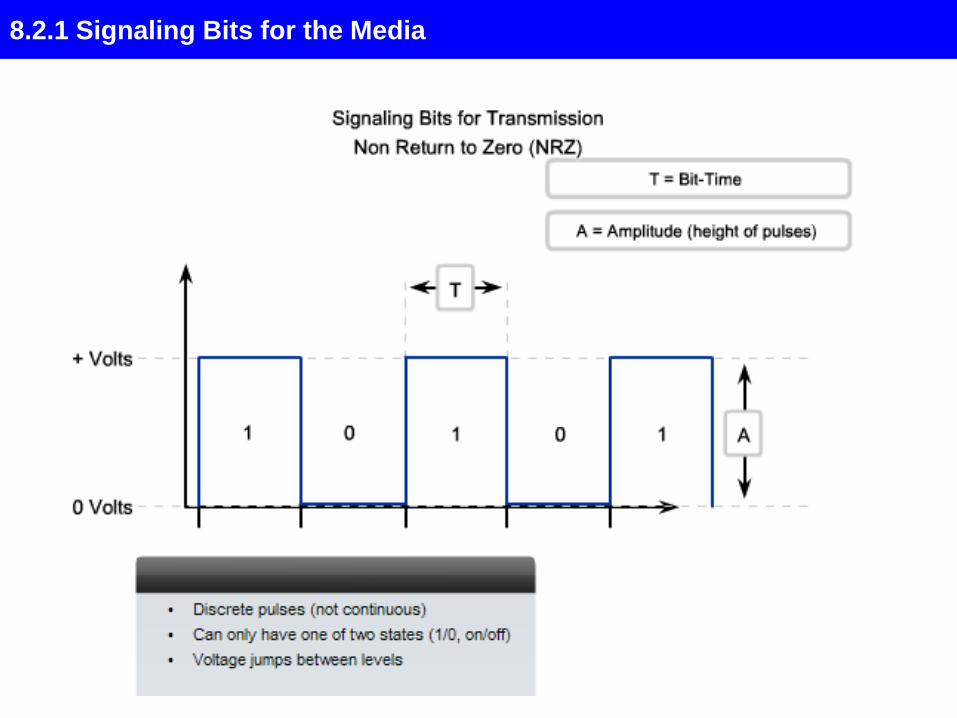
8.2.2 Encoding - Grouping Bits

8.2.2 Encoding - Grouping Bits
A code group is a
consecutive sequence of
code bits that are interpreted
and mapped as data bit
patterns. For example, code
bits 10101 could represent
the data bits 0011.
Although using code groups introduces overhead in the form of extra bits to
transmit, they improve the robustness of a communications link. This is
particularly true for higher speed data transmission.
8.2.2 Encoding - Grouping Bits

8.2.2 Encoding - Grouping Bits
4B/5B Encoding The encoding method used for encoding 4-bit data bytes to 5-bit
Transmission Characters.
Data bytes are converted to Transmission Characters to improve the physical
signal such that the following benefits are achieved:
• bit synchronization is more easily achieved,
• design of receivers and transmitters is simplified,
• error detection is improved, and
• control characters (i.e., the Special Character) can be distinguished from data
characters.
• 4B/5B encoding prevent symbols with more than three 0's in succession from
occurring in the stream.
The encoding advantage is that it can use NRZ-I encoding without losing
synchronization in case of long null sequences.
The disadvantage is the 25% overhead due to conversion from 4 to 5 bits.
Of the 32 different characters that the 4B/5B code can generate, only 16 characters
are needed to transfer the payload, the remaining 16 are used as control
characters

8.2.2 Non Return to Zero Encoding
NRZI [Non-Return-to-Zero-Inverted Encoding]: A '0' is encoded as no change in
the level. However a '1' is encoded depending on the current state of the line. If
the current state is '0' [low] the '1' will be encoded as a high, if the current state
is '1' [high] the '1' will be encoded as a low. Used with FDDI and USB for
example.
NRZI Encoding

8.2.3 Data Carrying Capacity

8.2.3 Data Carrying Capacity
Throughput is the measure of the
transfer of bits across the media
over a given period of time.
Goodput is the measure of usable
data transferred over a given
period of time, and is therefore the
measure that is of most interest to
network users.
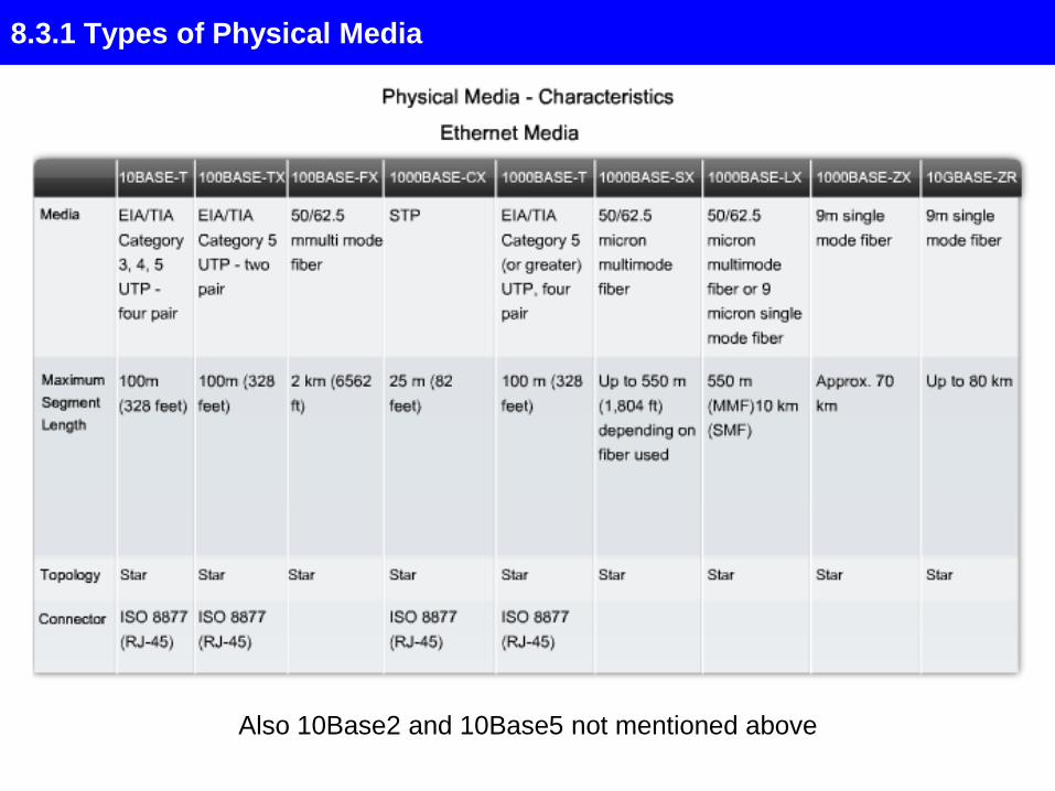
8.3.1 Types of Physical Media
Also 10Base2 and 10Base5 not mentioned above
8.3.1 Types of Physical Media

8.3.2 Copper Media

8.3.2 Copper Media
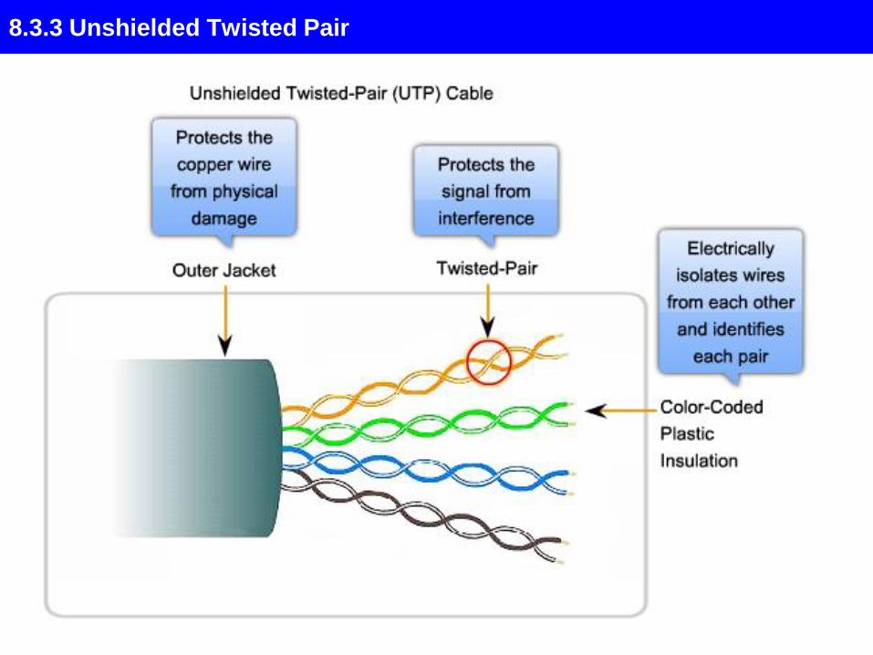
8.3.3 Unshielded Twisted Pair

8.3.3 Unshielded Twisted Pair

8.3.4 Other Copper Media

8.3.4 Other Copper Media

8.3.5 Copper Media Safety

8.3.6 Fiber Media

8.3.6 Fiber Media

8.3.6 Fiber Media
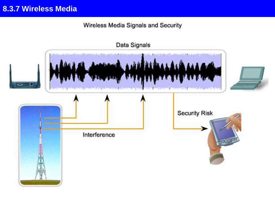
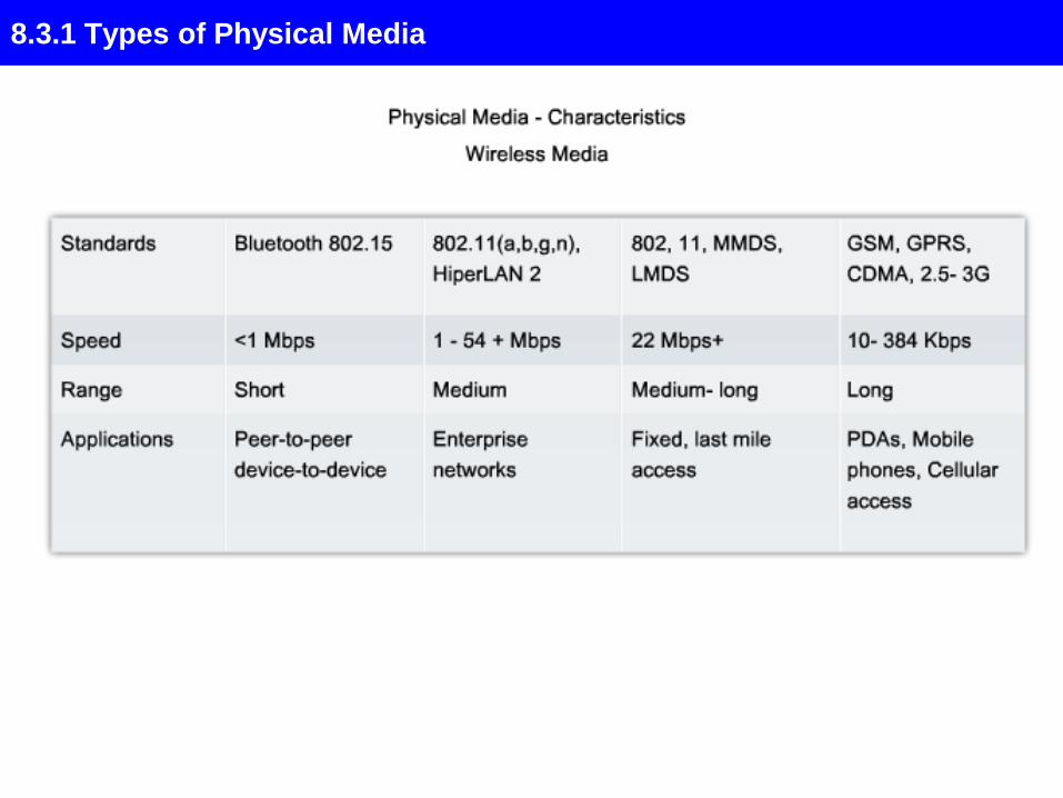
8.3.7 Wireless Media

8.3.7 Wireless Media

8.3.7 Wireless Media

8.3.8 Media Connectors

8.3.8 Media Connectors

8.3.8 Media Connectors

8.5.1 Summary and Review


A LAN can be as simple as
two computers, each having
a network interface card
(NIC) or network adapter and
running network software,
connected together with a
crossover cable.
The next step up would be a
network consisting of three or
more computers and a
hub. Each of the computers
is plugged into the hub with a
straight-thru cable (the
crossover function is
performed by the hub).

NETWORK CABLE AND
CONNECTORS
CAT 5 wire is available in reel-in-
box packaging. This is very handy
for pulling the wire without putting
twists in it. Without this kind of
package or a cable reel stand,
pulling wire is a two-person
job. Before the advent of the reel-
in-box, we used to put a reel of wire
on a broom handle to pull it. One
person would hold the broom
handle and the other would pull and
measure the cable. You will
produce a tangled mess, if you pull
the wire off the end of the reel.

CAT 5 cable has four twisted pairs
of wire for a total of eight
individually insulated wires. Each
pair is color coded with one wire
having a solid color (blue, orange,
green, or brown) twisted around a
second wire with a white
background and a stripe of the
same color. The solid colors may
have a white stripe in some
cables. Cable colors are commonly
described using the background
color followed by the color of the
stripe; e.g., white-orange is a cable
with a white background and an
orange stripe

CONNECTORS. The straight
through and cross-over patch cables are
terminated with CAT 5 RJ-45 modular
plugs.
RJ-45 plugs are similar to those you'll see
on the end of your telephone cable except
they have eight versus four or six contacts
on the end of the plug and they are about
twice as big.
Make sure they are rated for CAT 5
wiring. (RJ means "Registered
Jack"). Also, there are RJ-45 plugs
designed for both solid core wire and
stranded wire. Others are designed
specifically for one kind of wire or the
other


COLOR-CODE STANDARDS
Note that the TX (transmitter) pins are connected to
corresponding RX (receiver) pins, plus to plus and minus to
minus.
And that you must use a cossover cable to connect units
with identical interfaces. If you use a straight-through cable,
one of the two units must, in effect, perform the cross-over
function.
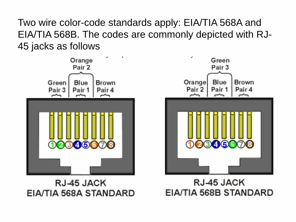
Two wire color-code standards apply: EIA/TIA 568A and
EIA/TIA 568B. The codes are commonly depicted with RJ-
45 jacks as follows

If we apply the 586A color code and show all eight wires, our
pin-out looks like this
Note that pins 4, 5, 7, and 8 and the blue and brown pairs are
not used in either standard. Quite contrary to what you may
read elsewhere, these pins and wires are not used or
required to implement 100BASE-TX duplexing--they are just
plain wasted

the actual cables are not physically that simple. In the
diagrams, the orange pair of wires are not adjacent. The
blue pair is upside-down. The right ends match RJ-45 jacks
and the left ends do not. If, for example, we invert the left
side of the 586A "straight"-thru cable to match a 586A jack--
put one 180° twist in the entire cable from end-to-end--and
twist together and rearrange the appropriate pairs, we get
the following can-of-worms

This further emphasizes, I hope, the importance of the word
"twist" in making network cables which will work.
You cannot use an flat-untwisted telephone cable for a
network cable.
Furthermore, you must use a pair of twisted wires to connect
a set of transmitter pins to their corresponding receiver pins.
You cannot use a wire from one pair and another wire from a
different pair

Keeping the above principles in mind, we can simplify the
diagram for a 568A straight-thru cable by untwisting the
wires, except the 180° twist in the entire cable, and bending
the ends upward.
Likewise, if we exchange the green and orange pairs in the
568A diagram we will get a simplified diagram for a 568B
straight-thru cable.
If we cross the green and orange pairs in the 568A diagram
we will arrive at a simplified diagram for a crossover cable


There are only
two unique
cable ends in
the preceding
diagrams. They
correspond to
the 568A and
568B RJ-45
jacks and are
shown to the
right

Now, all you need to remember, to properly configure the
cables, are the diagrams for the two cable ends and the
following rules:
•A straight-thru cable has identical ends.
•A crossover cable has different ends.
It makes no functional difference which standard you use for
a straight-thru cable. You can start a crossover cable with
either standard as long as the other end is the other
standard. It makes no functional difference which end is
which. Despite what you may have read elsewhere, a 568A
patch cable will work in a network with 568B wiring and 568B
patch cable will work in a 568A network. The electrons
couldn't care less.

LET'S MAKE SOME CABLES
Strip one end of the cable with the
stripper or a knife and diags. If you
are using the stripper, place the cable
in the groove on the blade (left) side of
the stripper and align the end of the
cable with the right side of the
stripper. This will strip about 1/2" of
the jacket off the cable. Turn the
stripper about 1 1/4 turns and pull. If
you turn it more, you will probably nick
the wires. If you are using a knife and
diags, carefully slit the cable for about
an inch or so and neatly trim around
the circumference of the cable with
diags to remove the jacket.

Spread and arrange the
pairs roughly in the order of
the desired cable end.

Untwist the pairs and arrange the
wires in the order of the desired
cable end. Flatten the end
between your thumb and
forefinger. Trim the ends of the
wires so they are even with one
another. It is very important that
the unstripped (untwisted) end
be slightly less than 1/2"
long. If it is longer than 1/2" it will
be out-of-spec and susceptible to
crosstalk. If it less than slightly
less than 1/2" it will not be properly
clinched when RJ-45 plug is
crimped on.. Flatten again. There
should be little or no space
between the wires.

Hold the RJ-45 plug with the clip
facing down or away from
you. Push the wire firmly into
the plug. Now, inspect the
darn thing... before crimping
and wasting the plug! Looking
through the bottom of the plug,
the wire on the far left side will
have a white background. The
wires should alternate light and
dark from left to right. The
furthest right wire is brown. The
wires should all end evenly at
the front of the plug. The jacket
should end just about where
you see it in the diagram--right
on the line.
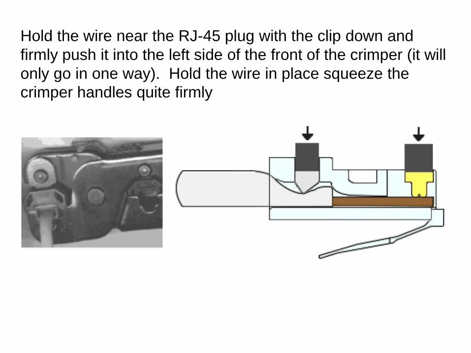
Hold the wire near the RJ-45 plug with the clip down and
firmly push it into the left side of the front of the crimper (it will
only go in one way). Hold the wire in place squeeze the
crimper handles quite firmly

CABLING RULES
1. Try to avoid running cables parallel to
power cables.
2. Do not bend cables to less than four
times the diameter of the cable.
3. If you bundle a group of cables together
with cable ties (zip ties), do not over-
cinch them. It's okay to snug them
together firmly; but don't tighten them so
much that you deform the cables.

4. Keep cables away from devices which
can introduce noise into them. Here's
a short list: copy machines, electric
heaters, speakers, printers, TV sets,
fluorescent lights, copiers, welding
machines, microwave ovens,
telephones, fans, elevators motors,
electric ovens, dryers, washing
machines, and shop equipment.
5. Avoid stretching UTP cables (the force
should not exceed 25 LBS).
6. Do not run UTP cable outside of a
building. It presents a very dangerous
lightning hazard!
7. Do not use a stapler to secure UTP
cables. Use telephone wire hangers
which are available at most hardware
stores.


![OSI Physical Layer - · PDF fileCisco Public 3. Physical Layer Protocols & Services ... Microsoft PowerPoint - Exploration_Network_Chapter8.ppt [Compatibility Mode] Author:](https://img.pdfslide.us/doc/110x75/5aa424f47f8b9ae7438ba04f/osi-physical-layer-public-3-physical-layer-protocols-services-microsoft-powerpoint.jpg)