Embed Size (px)
Citation preview
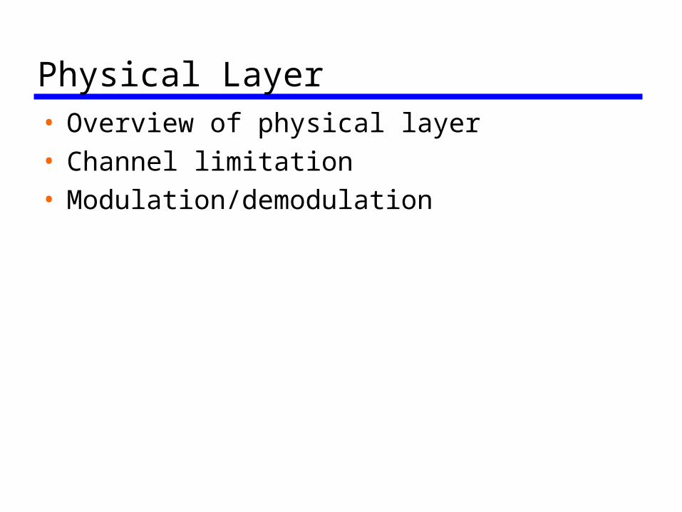
Physical Layer• Overview of physical layer• Channel limitation• Modulation/demodulation
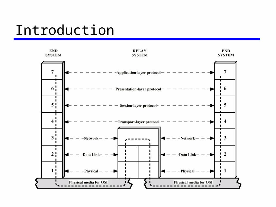
Introduction
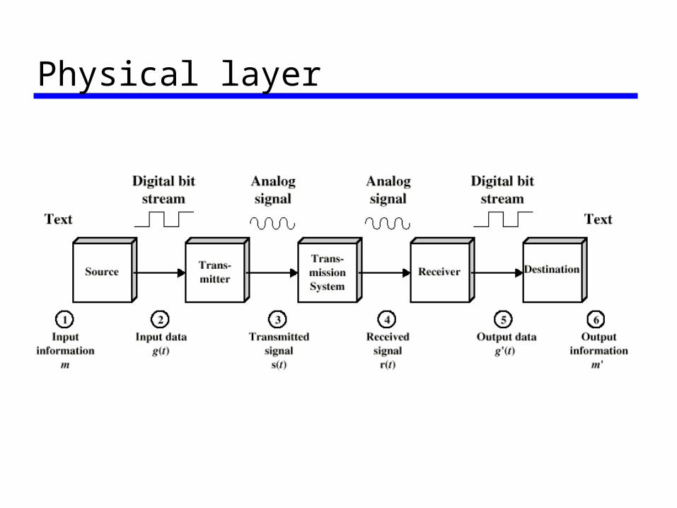
Physical layer
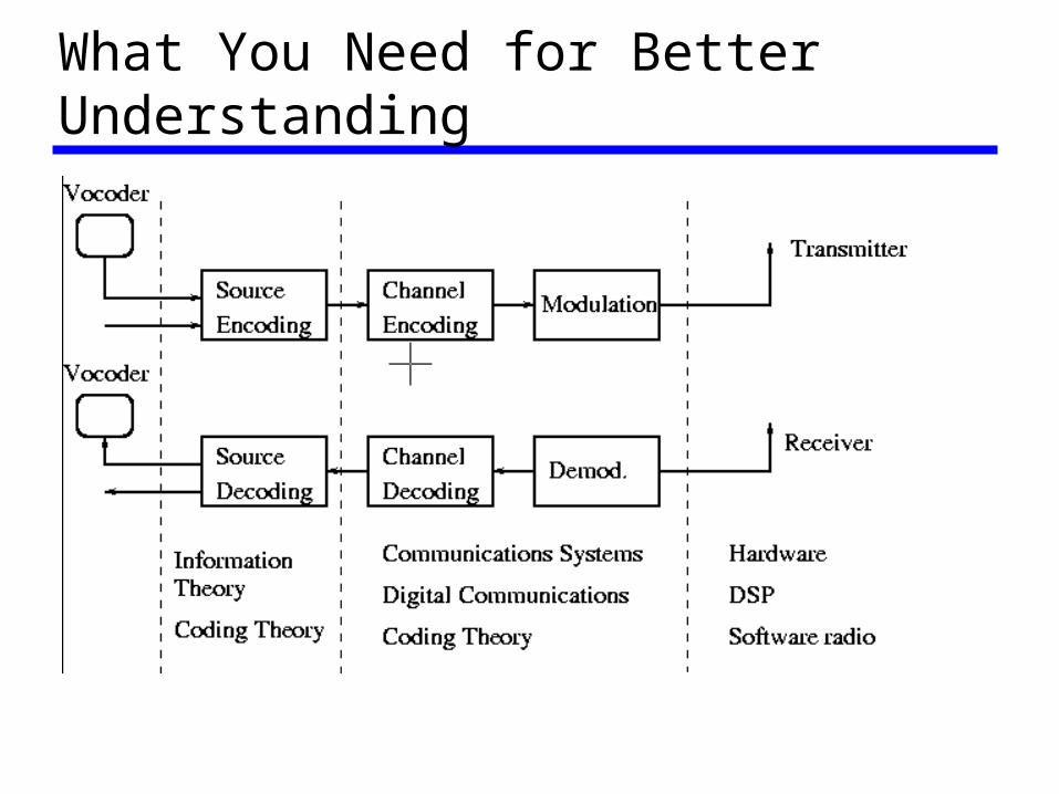
What You Need for Better Understanding
Representation of Information• Digital representation
– Information that occurs naturally in digital form
data files or image files
– Analog information: be digitized Voice Music Video
• Most communications networks are digital!
Source Coding• Networks are handling streams of 0’s and
1’ • Source Encoding: compression, according
to statistics of 0’s and 1’s, map blocks of bits to more regular “shorter” blocks! Get rid of redundancy
• Source Decoding: inverse of source encoding
Channel Coding• Channel Encoding: According to channel
conditions, add redundancy for more efficient transmission, interleaving may be used too.
• Channel decoding: the inverse• Observation: source encoding attempts to
eliminate “useless information”, while channel encoding add “useful information”, both deal with redundancies!
Modulation/Demodulation• Modulation: maps blocks of bits to well-
defined waveforms or symbols (a set of signals for better transmission), then shifts transmission to the carrier frequency band (the band you have right to transmit)
• Demodulation: the inverse of modulation • Demodulation vs. Detection: Detection is
to recover the modulated signal from the “distorted noisy” received signals
Physical Components• Transmitter• Receiver• Transmission media
– Guided: cable, twisted pair, fiber – Unguided: wireless (radio, infrared)
Signal Types• Basic form: A signal is a time function • Continuous signal: varying continuously with
time, e.g., speech • Discrete signal: varying at discrete time
instant or keeping constant value in certain time interval, e.g., Morse code, flash lights
• Periodic signal: Pattern repeated over time• Aperiodic signal: Pattern not repeated over
time, e.g., speech
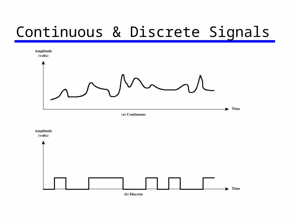
Continuous & Discrete Signals
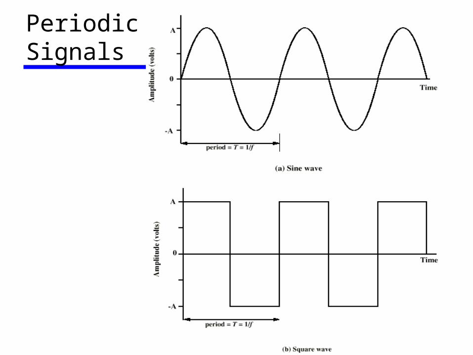
Periodic Signals
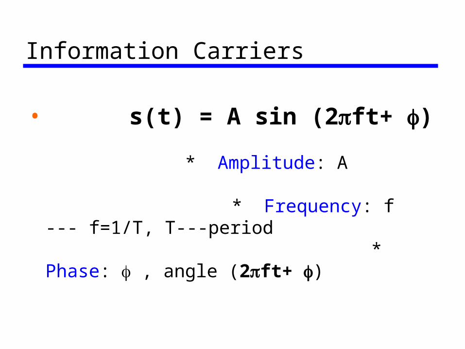
Information Carriers
• s(t) = A sin (2ft+ )
* Amplitude: A
* Frequency: f --- f=1/T, T---period
* Phase: , angle (2ft+ )
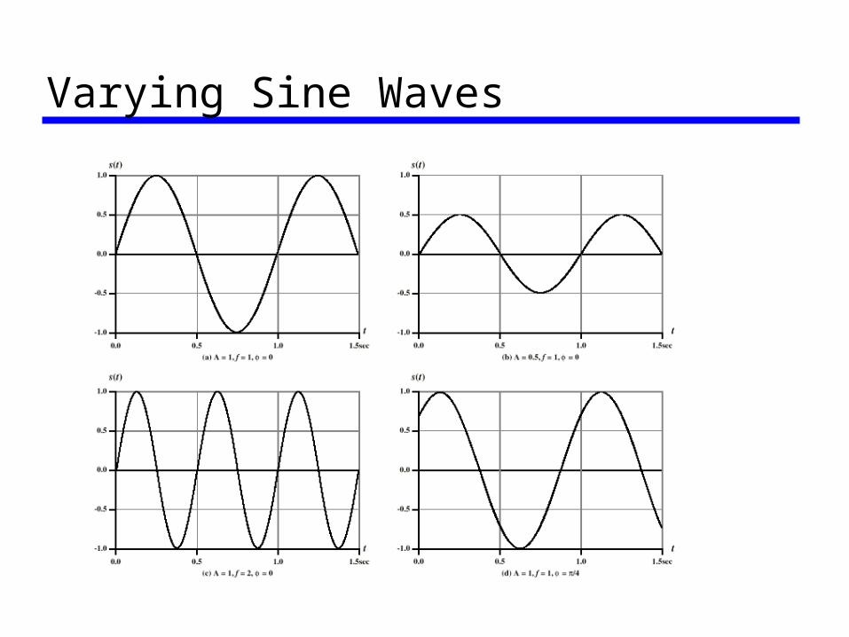
Varying Sine Waves
Frequency Domain Concept• Signal is usually made up of many
frequencies• Components are sine waves• Can be shown (Fourier analysis) that any
signal is made up of component sine waves• Can plot frequency domain functions• Time domain representation is equivalent
to frequency domain representation: they contain the same information!
• Frequency domain representation is easier for design
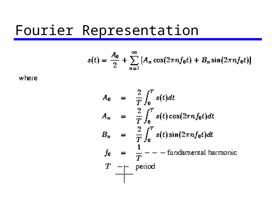
Fourier Representation
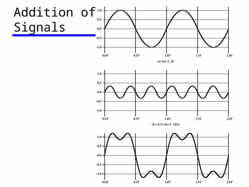
Addition ofSignals
Received Signals• Any receiver can only receive signals in
certain frequency range (channel concept), corresponding to finite number of terms in the Fourier series approximation: – physically: finite number of harmonics– mathematically: finite number of terms
• Transmitted signal design: allocate as many terms as possible in the intended receiver’s receiving range (most of power is limited in the intended receiving band)
Spectrum & Bandwidth• Spectrum: the range of frequencies
contained in a signal• Absolute bandwidth: width of spectrum• Effective bandwidth: just BW, Narrow band
of frequencies containing most of the energy– 3 dB BW– Percentage BW: percentage power in the band
• DC Component: Component of zero frequency
Data Rate and Bandwidth• Any transmission system has a limited
band of frequencies• This limits the data rate that can be
carried• The greater the BW, the higher the data
rate• Channel capacity (later)
Analog vs Digital• Analog: Continuous values within some
interval, the transmitted signal has actual meaning, e.g., AM and FM radio
• Digital: Digital=DSP+Analog, raw digital bits are processed and mapped to well-known signal set for better transmission, the final transmitted signal is still analog! You could not “hear” though!
Analog Transmission• Analog signal transmitted without regard
to content• Attenuated over distance• Use amplifiers to boost signal, equalizers
may be used to mitigate the noise • Also amplifies noise
Digital Transmission• Concerned with content• Digital repeaters used: repeater receives
signal, extracts bit pattern and retransmits the bit pattern!
• Attenuation is overcome and distortion is not propagated!
Advantages of Digital Transmission• Digital technology: low cost, can use low
power• Long distance transmission: use digital
repeaters• Capacity utilization: get rid of useless
information and add useful redundancy for data protection
• Security & privacy: encryption• Integration: treat analog and digital data
similarly
Channel Impairments• Attenuation and attenuation distortion:
signal power attenuates with distance • Delay distortion: velocity of a signal
through a guided medium varies with frequency, multipath in wireless environments
• Thermal noise• Co-channel Interference: wireless • Impulse noise (powerline communications)
Channel Capacity• Data rate is limited by channel bandwidth
and channel environment (impairments) • Data rate, in bits per second, is the
number of bits transmitted successfully per second! Should not count the redundancy added against channel impairments!
• It represents how fast bits can be transmitted reliably over a given medium
Factors Affecting Data Rate• Transmitted power (energy) • Distance between transmitter and
receiver • Noise level (including interference level) • Bandwidth
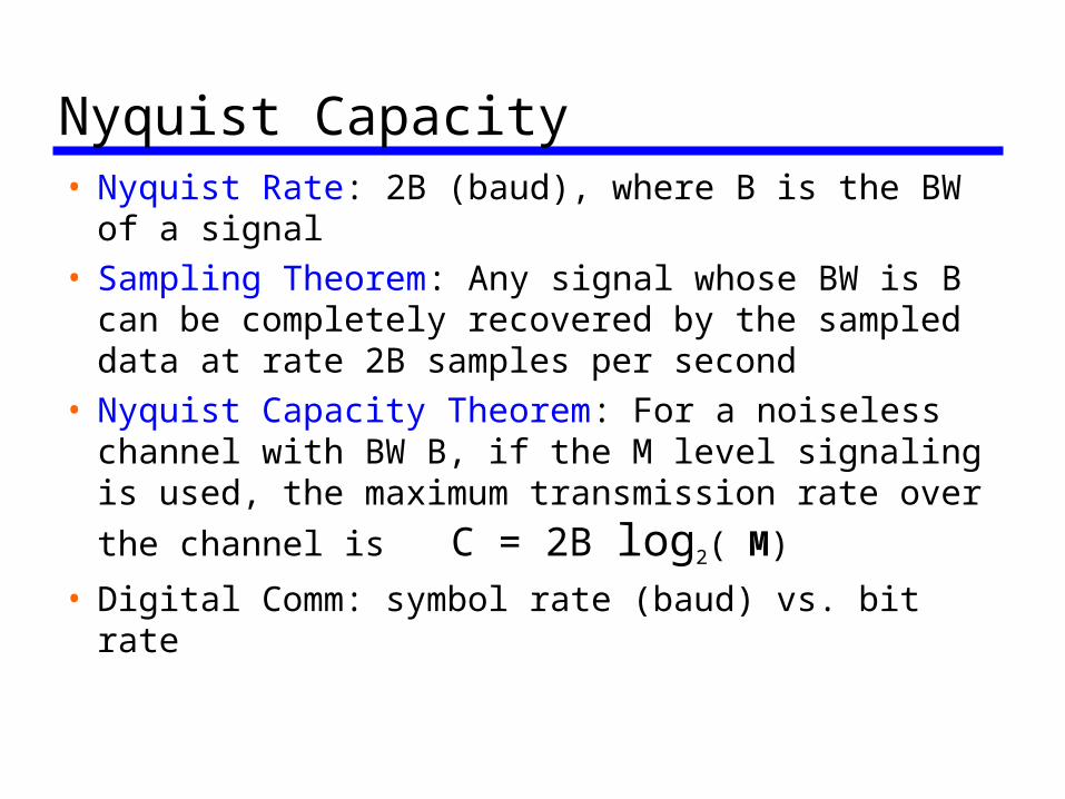
Nyquist Capacity• Nyquist Rate: 2B (baud), where B is the BW of a
signal• Sampling Theorem: Any signal whose BW is B
can be completely recovered by the sampled data at rate 2B samples per second
• Nyquist Capacity Theorem: For a noiseless channel with BW B, if the M level signaling is used, the maximum transmission rate over the channel is C = 2B log2( M)
• Digital Comm: symbol rate (baud) vs. bit rate
Shannon Capacity • All channels are noisy! • 1948 paper by Claude Shannon:
“A mathematical theory of communications” “The mathematical theory of communications”
• Signal-to-noise ratio:
SNR=signal power/noise power (watt)
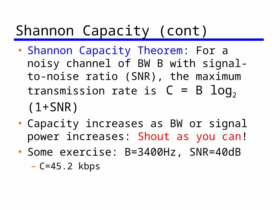
Shannon Capacity (cont)• Shannon Capacity Theorem: For a noisy
channel of BW B with signal-to-noise ratio (SNR), the maximum transmission rate is
C = B log2 (1+SNR)• Capacity increases as BW or signal power
increases: Shout as you can! • Some exercise: B=3400Hz, SNR=40dB
– C=45.2 kbps
Shannon Capacity (cont)• Shannon Theorem does not give any way
to reach that capacity• Current transmission schemes transmit
much lower rate than Shannon capacity• Turbo codes: iterative coding schemes
using feedback information for transmission and detection
• Sailing towards Shannon capacity!
Modulation/Demodulation• Line coding: representation of binary bits
without carrier (baseband coding) • Modulation/demodulation: representation
of digital bits with carrier (broadband coding)
• Analog to Digital Coding
Line Coding• Unipolar: all signal elements have same sign• Polar: one logic state represented by positive
voltage the other by negative voltage• Data rate: rate of transmitted data (bps) • Bit period: time taken for transmitter to emit
the bit, the duration or length of a bit• Modulation rate: rate at which the signal
level changes, measured in baud (symbols per sec)
Schemes• Non-return to Zero-Level (NRZ-L)• Non-return to Zero Inverted (NRZI)• Bipolar-AMI• Pseudo-ternary• Manchester• Differential Manchester
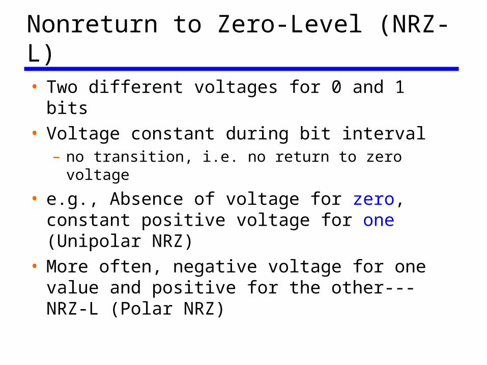
Nonreturn to Zero-Level (NRZ-L)• Two different voltages for 0 and 1 bits• Voltage constant during bit interval
– no transition, i.e. no return to zero voltage
• e.g., Absence of voltage for zero, constant positive voltage for one (Unipolar NRZ)
• More often, negative voltage for one value and positive for the other---NRZ-L (Polar NRZ)
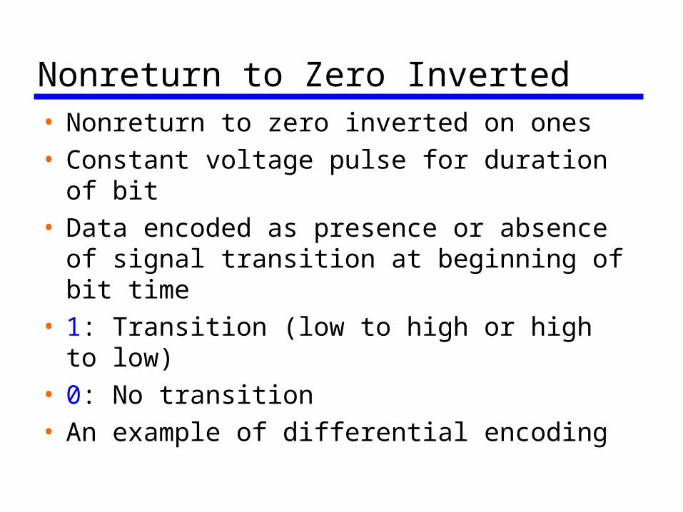
Nonreturn to Zero Inverted• Nonreturn to zero inverted on ones• Constant voltage pulse for duration of bit• Data encoded as presence or absence of
signal transition at beginning of bit time• 1: Transition (low to high or high to low)• 0: No transition• An example of differential encoding
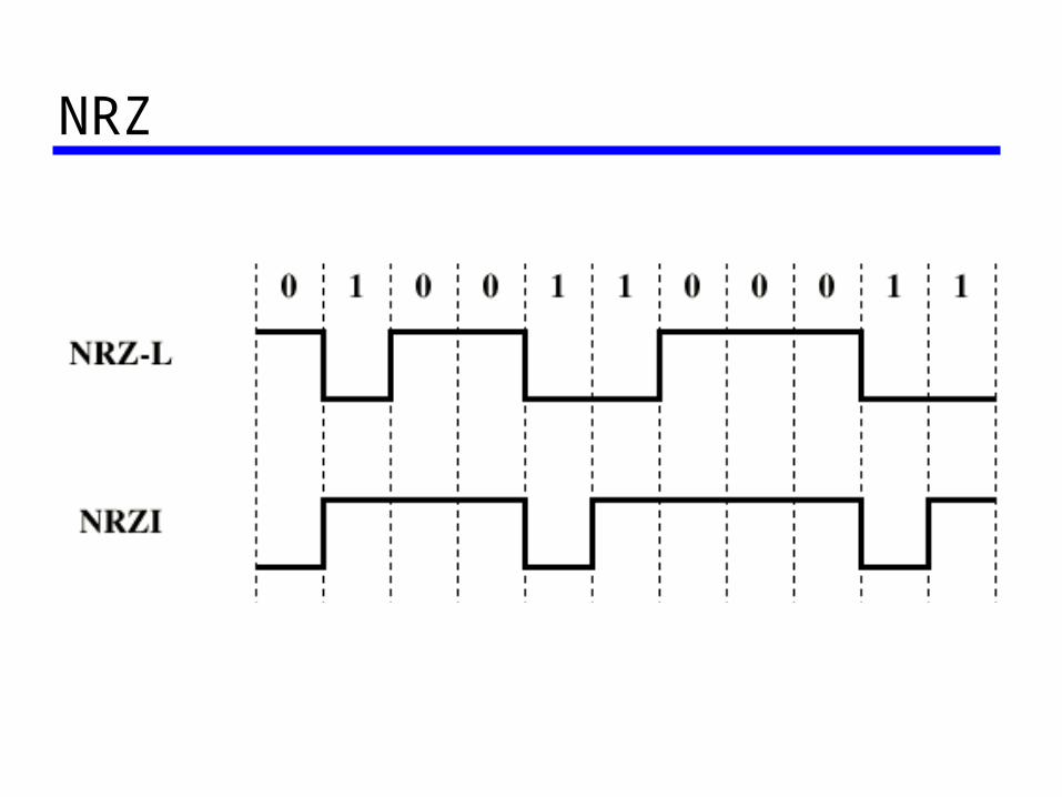
NRZ
Differential Encoding• Data represented by changes rather than
levels• More reliable detection of transition rather
than level• In complex transmission layouts it is easy
to lose sense of polarity
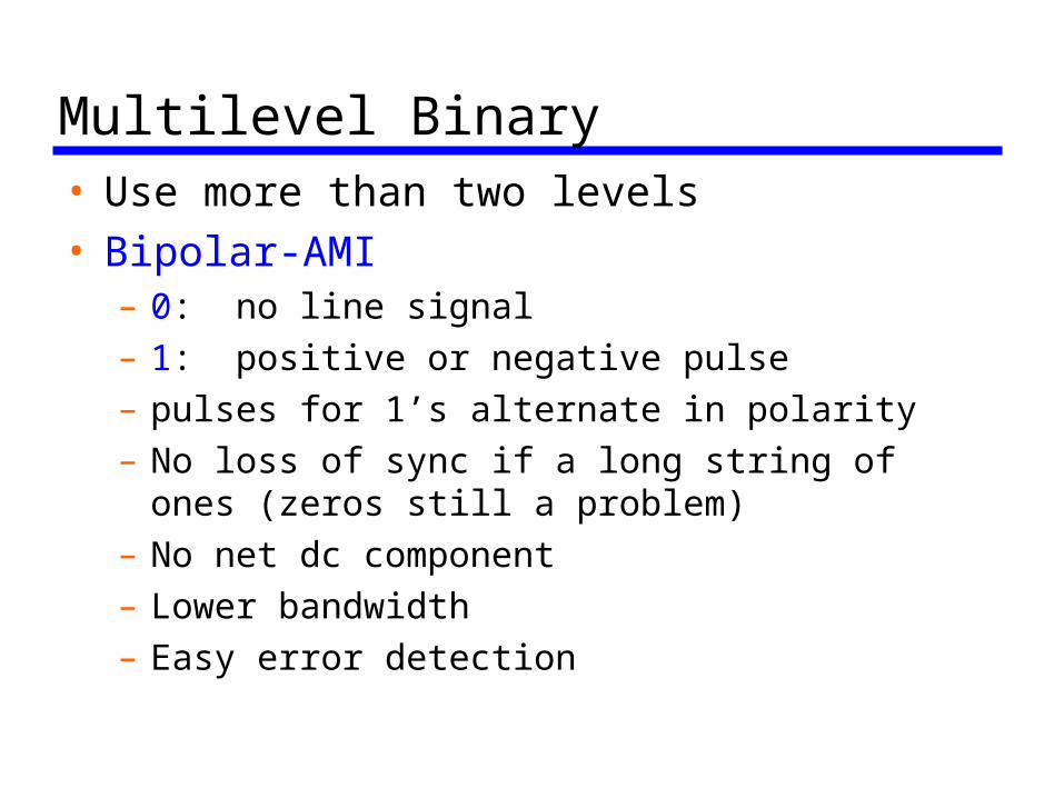
Multilevel Binary• Use more than two levels• Bipolar-AMI
– 0: no line signal– 1: positive or negative pulse– pulses for 1’s alternate in polarity– No loss of sync if a long string of ones (zeros
still a problem)– No net dc component– Lower bandwidth– Easy error detection
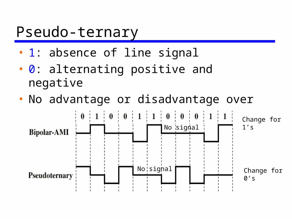
Pseudo-ternary• 1: absence of line signal• 0: alternating positive and negative• No advantage or disadvantage over
bipolar-AMI
Change for1’s
Change for 0’s
No signal
No signal
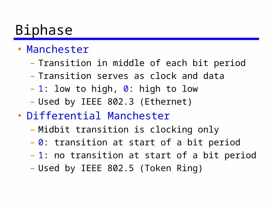
Biphase• Manchester
– Transition in middle of each bit period– Transition serves as clock and data– 1: low to high, 0: high to low – Used by IEEE 802.3 (Ethernet)
• Differential Manchester– Midbit transition is clocking only– 0: transition at start of a bit period – 1: no transition at start of a bit period– Used by IEEE 802.5 (Token Ring)
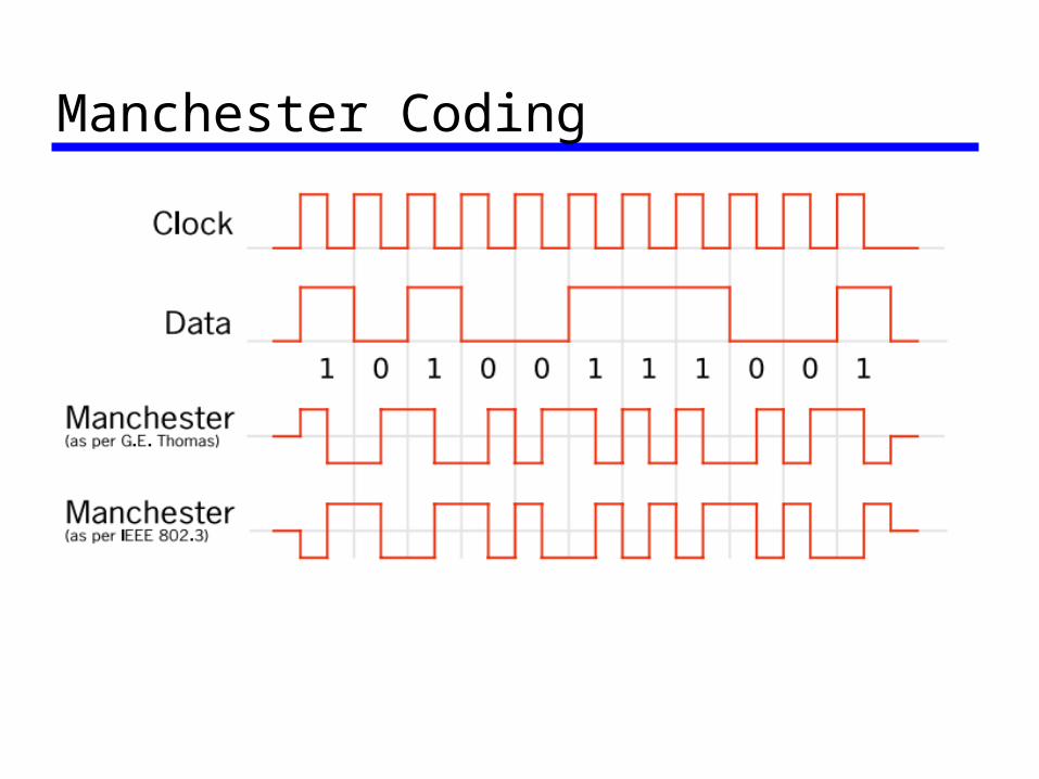
Manchester Coding
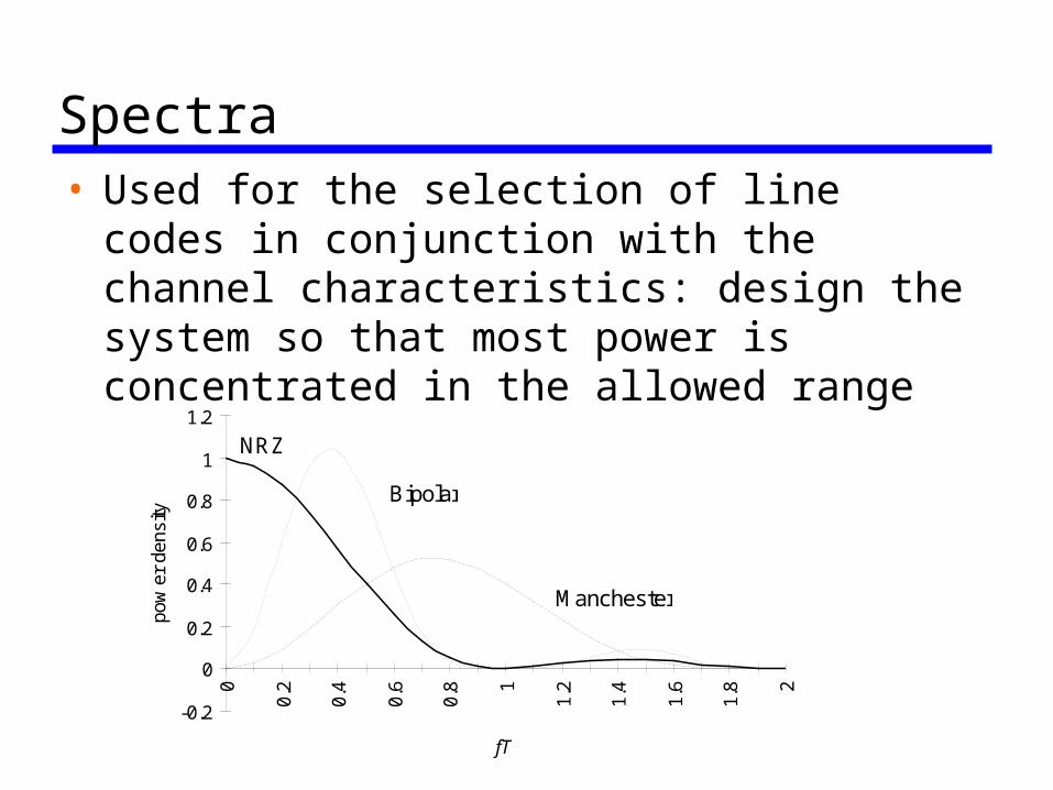
Spectra• Used for the selection of line codes in
conjunction with the channel characteristics: design the system so that most power is concentrated in the allowed range
-0.2
0
0.2
0.4
0.6
0.8
1
1.2
0
0.2
0.4
0.6
0.8 1
1.2
1.4
1.6
1.8 2
fT
pow
er d
ensi
ty
NRZ
Bipolar
Manchester
Modulation Schemes (Binary)• Public telephone system
– 300Hz to 3400Hz– Use modem (modulator-demodulator)
• Amplitude Shift Keying (ASK)• Frequency Shift Keying (FSK)• Phase Shift Keying (PSK)
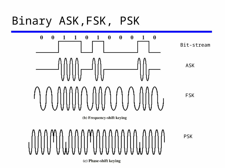
Binary ASK,FSK, PSK
Bit-stream
ASK
FSK
PSK
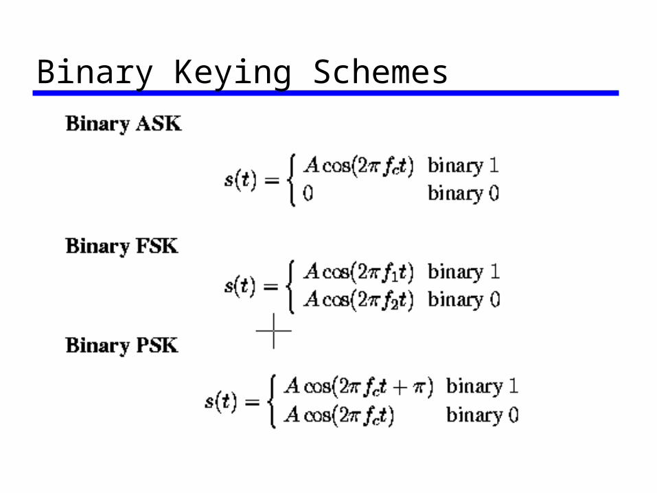
Binary Keying Schemes
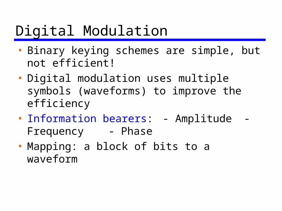
Digital Modulation• Binary keying schemes are simple, but not
efficient! • Digital modulation uses multiple symbols
(waveforms) to improve the efficiency• Information bearers:
- Amplitude - Frequency- Phase
• Mapping: a block of bits to a waveform
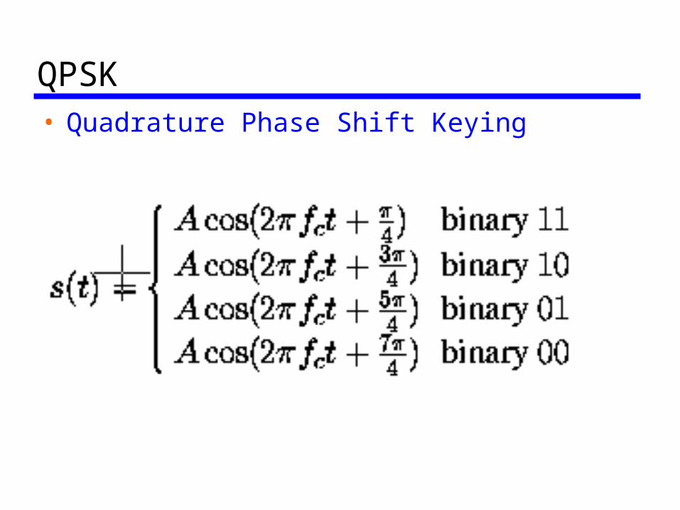
QPSK• Quadrature Phase Shift Keying
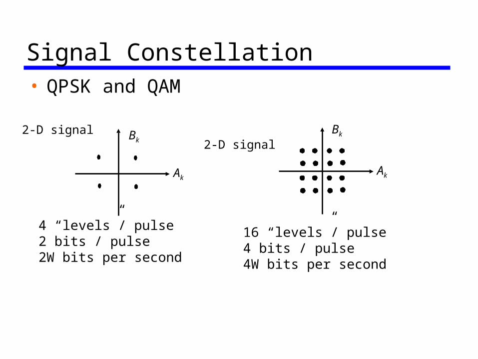
Signal Constellation• QPSK and QAM
Ak
Bk
16 “levels”/ pulse4 bits / pulse4W bits per second
Ak
Bk
4 “levels”/ pulse2 bits / pulse2W bits per second
2-D signal2-D signal
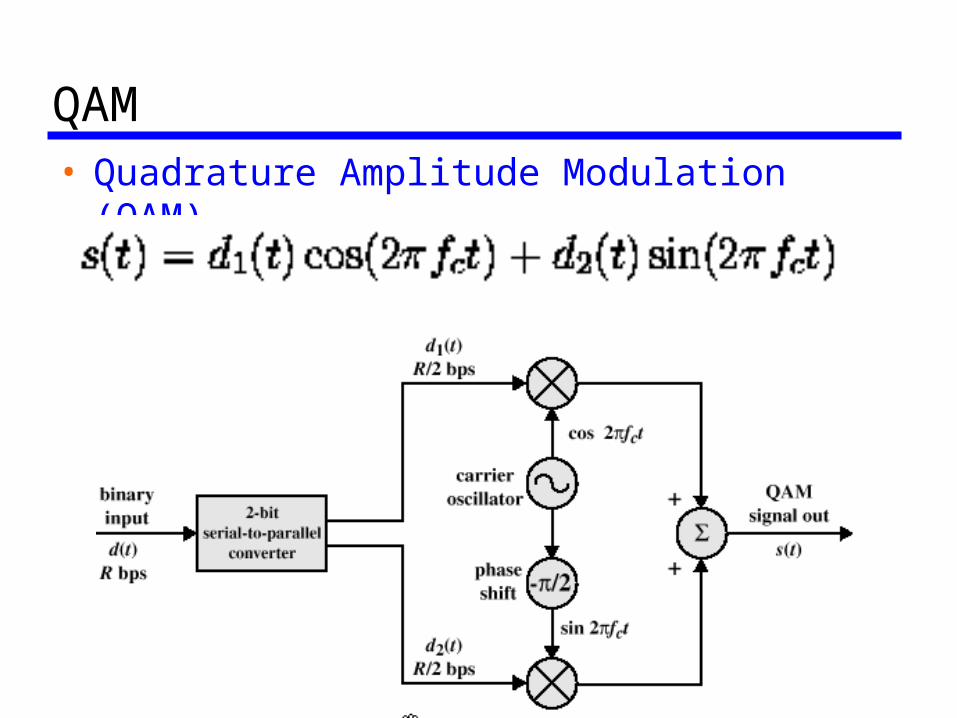
QAM• Quadrature Amplitude Modulation (QAM)
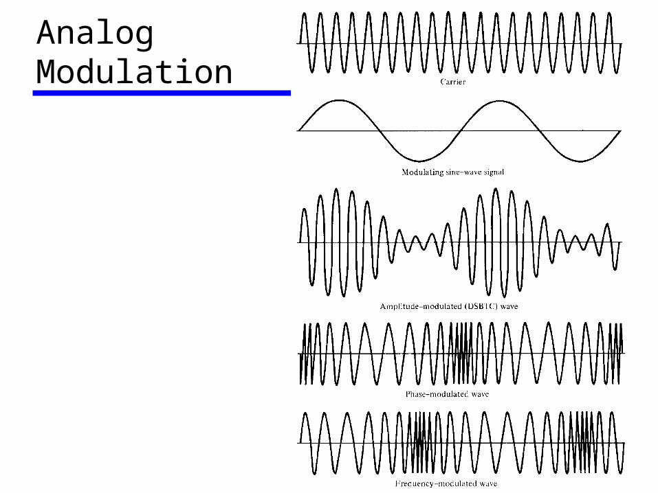
Analog Modulation
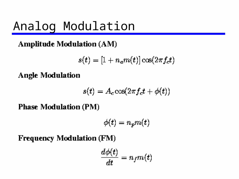
Analog Modulation
Analog to Digital• Sampling Theorem • Quantization • Pulse Coded Modulation (PCM) • Differentially coded Modulation (e.g.,
Delta Modulation)
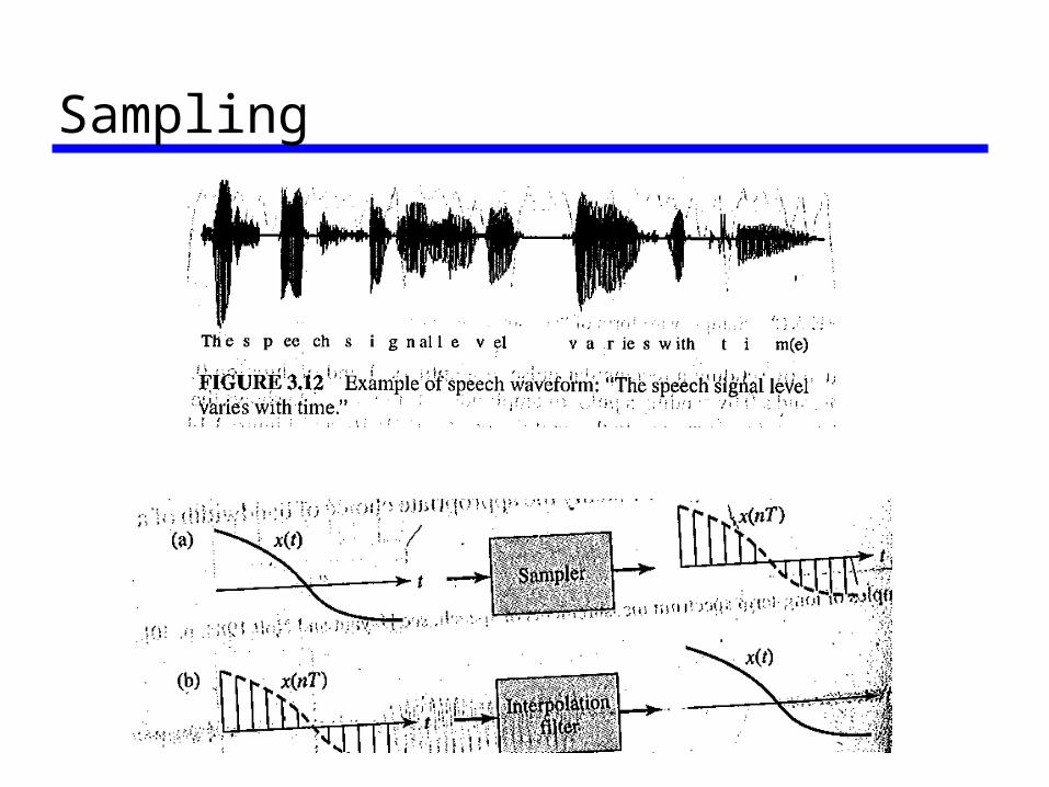
Sampling
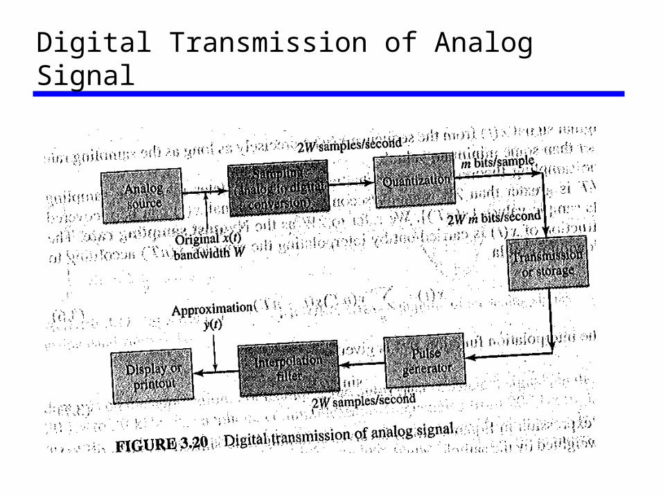
Digital Transmission of Analog Signal
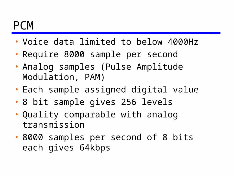
PCM• Voice data limited to below 4000Hz• Require 8000 sample per second• Analog samples (Pulse Amplitude
Modulation, PAM)• Each sample assigned digital value• 8 bit sample gives 256 levels• Quality comparable with analog
transmission• 8000 samples per second of 8 bits each
gives 64kbps
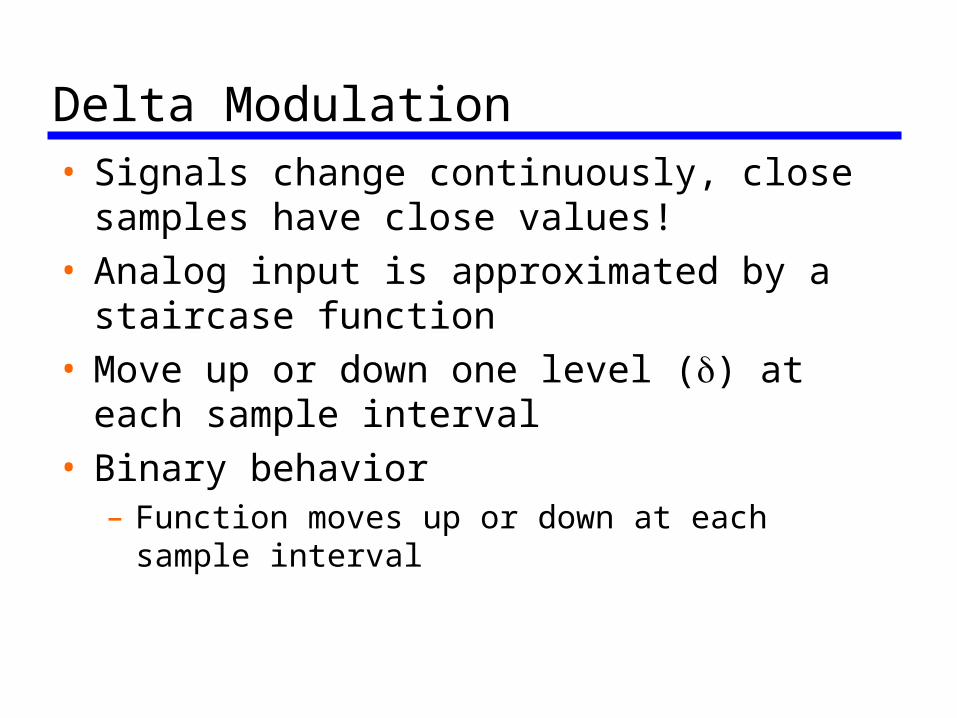
Delta Modulation• Signals change continuously, close
samples have close values! • Analog input is approximated by a
staircase function• Move up or down one level () at each
sample interval• Binary behavior
– Function moves up or down at each sample interval
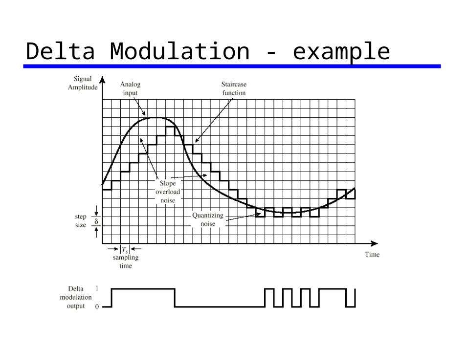
Delta Modulation - example
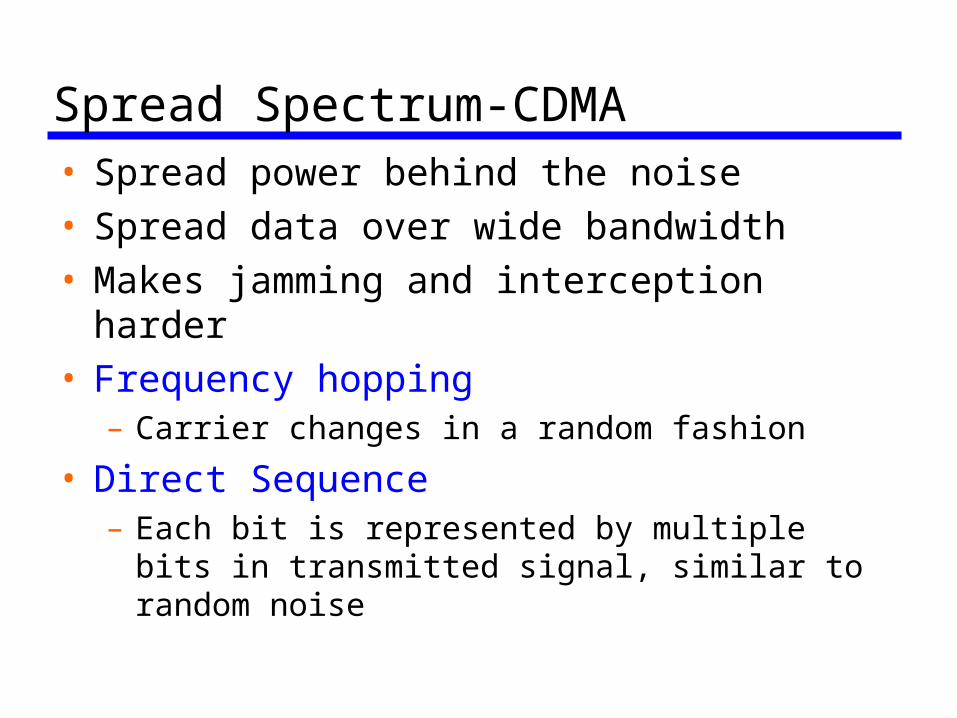
Spread Spectrum-CDMA• Spread power behind the noise• Spread data over wide bandwidth • Makes jamming and interception harder• Frequency hopping
– Carrier changes in a random fashion
• Direct Sequence– Each bit is represented by multiple bits in
transmitted signal, similar to random noise
Transmission Media• Guided - wired (cable, twisted-pair, fiber)• Unguided - wireless (radio, infrared,
microwave)• For guided, the medium is more important• For unguided, the transmission bandwidth
and channel conditions are more important
• Key concerns are data rate and distance
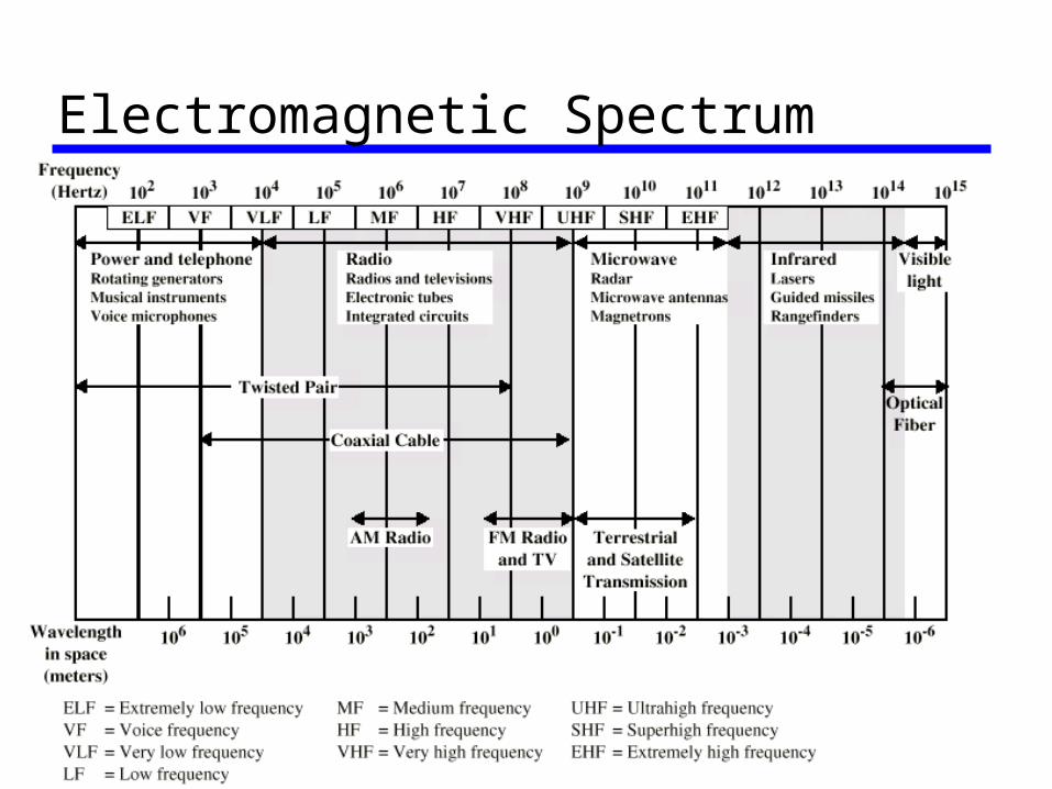
Electromagnetic Spectrum
Guided Transmission Media• Twisted Pair• Coaxial cable• Optical fiber
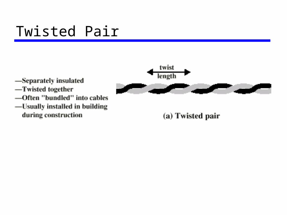
Twisted Pair
Twisted Pair (cont)• Most common medium• Telephone networks and local area networks
(Ethernet)• Easy to work with and cheap• Limited BW and low date rate, short distance
and susceptible to interference and noise• New technologies: xDSL-digital subscriber
line e.g., ADSL, VDSL– DMT: Discrete Multitone (Cioffi’s successful story)
Unshielded and Shielded TP• Unshielded Twisted Pair (UTP)
– Ordinary telephone wire– Cheapest– Easiest to install– Suffers from external EM interference
• Shielded Twisted Pair (STP)– Metal braid or sheathing that reduces
interference– More expensive– Harder to handle (thick, heavy)
EIA-568-A UTP Categories• Cat 3: up to 16MHz (LANs)
– Voice grade found in most offices– Twist length of 7.5 cm to 10 cm– data rate up to 16 Mbps, found in most office
building
• Cat 4: up to 20 MHz• Cat 5: up to 100MHz (LANs)
– Commonly pre-installed in new office buildings– Twist length 0.6 cm to 0.85 cm– Data rate up to 100 Mbps

Coaxial Cable
Coaxial Cable (cont)• Most versatile medium• Television distribution: TV, CATV• Long distance telephone transmission: can
carry 10,000 voice calls simultaneously• Short distance computer systems links,
LAN• Higher BW and high date rate• Heavy, not flexible, optical fibers may be
a better choice
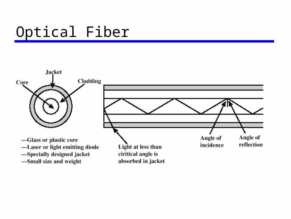
Optical Fiber
Optical Fiber (cont)• Greater capacity:
– High BW ( >100 THz) and Data rates of hundreds of Gbps
• Smaller size & weight• Lower attenuation• Electromagnetic isolation• More secure transmission: infeasible
wiretap• Greater repeater spacing
– 10s of km at least
Optical Fiber (cont)• Light Emitting Diode (LED)
– Cheaper– Wider operating temp range– Last longer
• Injection Laser Diode (ILD)– More efficient– Greater data rate– More expensive
• Wavelength Division Multiplexing (WDM)
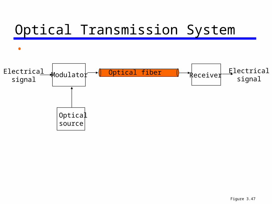
Optical Transmission System •
Optical fiber
Opticalsource
ModulatorElectricalsignal
ReceiverElectrical
signal
Figure 3.47
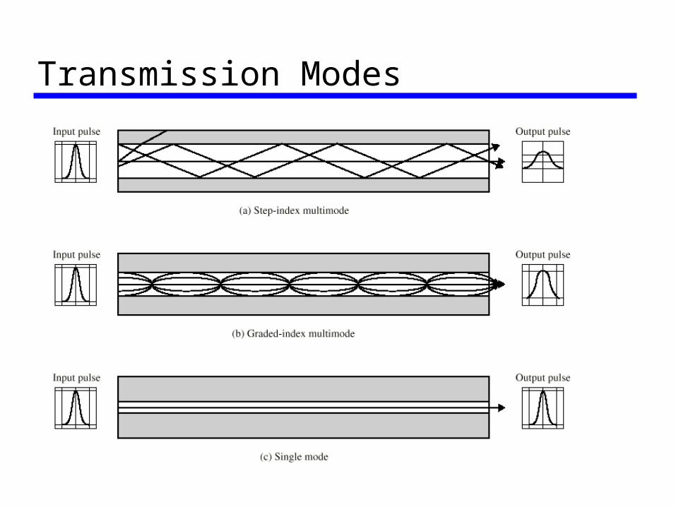
Transmission Modes
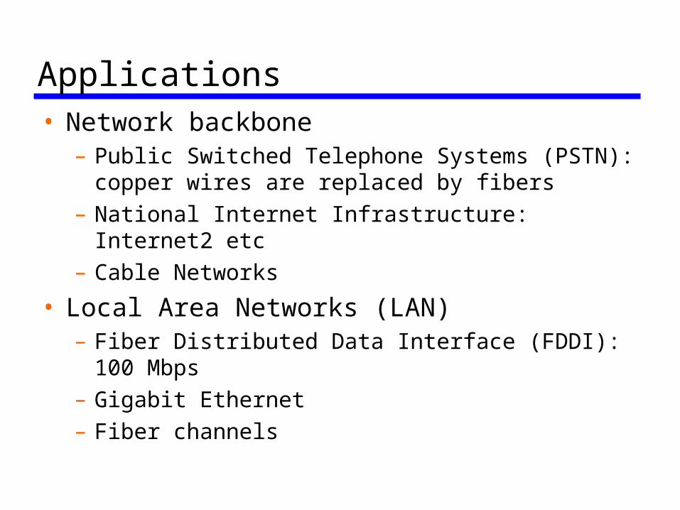
Applications• Network backbone
– Public Switched Telephone Systems (PSTN): copper wires are replaced by fibers
– National Internet Infrastructure: Internet2 etc – Cable Networks
• Local Area Networks (LAN) – Fiber Distributed Data Interface (FDDI): 100
Mbps – Gigabit Ethernet – Fiber channels
Wireless Transmission• Unguided media: transmission over the air • Transmission and reception via antenna• Directional
– Transmission limited in certain direction (flash light)
– Careful alignment required
• Omni-directional– Transmission power evenly spread over all
directions (fireworks)– Can be received by many antennae
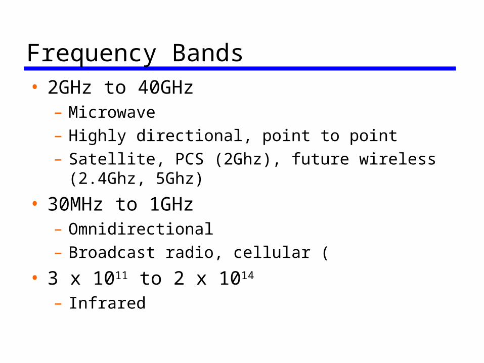
Frequency Bands• 2GHz to 40GHz
– Microwave– Highly directional, point to point– Satellite, PCS (2Ghz), future wireless (2.4Ghz,
5Ghz)
• 30MHz to 1GHz– Omnidirectional– Broadcast radio, cellular (
• 3 x 10¹¹ to 2 x 10¹⁴
– Infrared
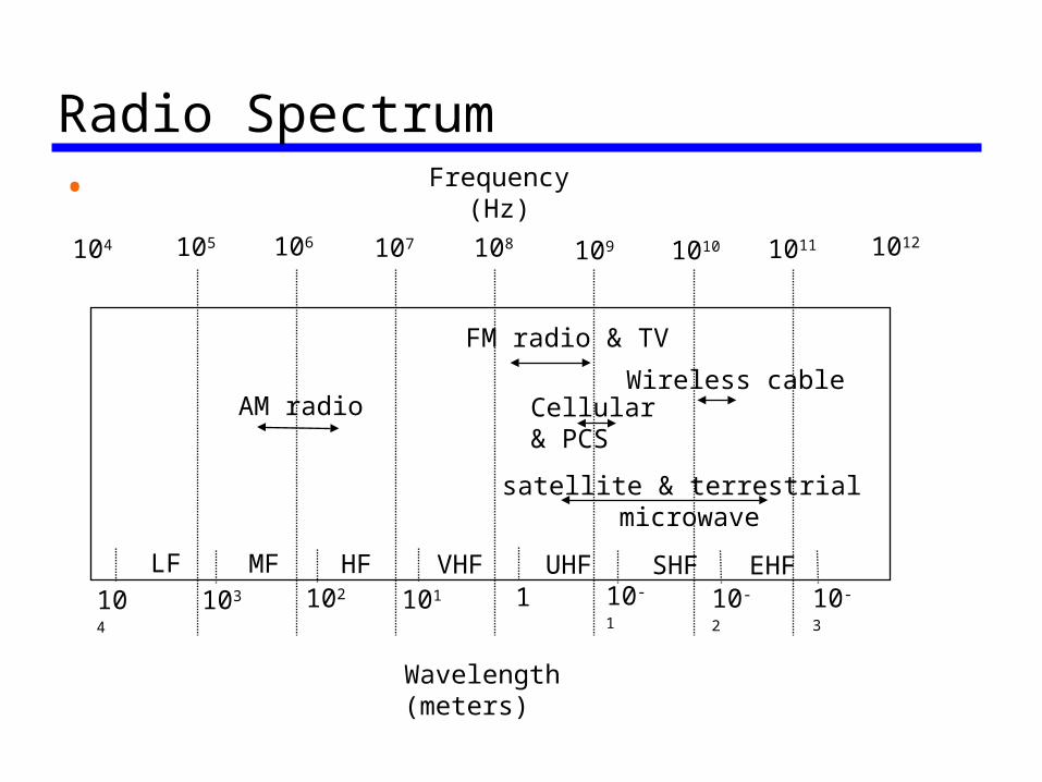
Radio Spectrum•
104 106 107 108 109 1010 1011 1012
Frequency (Hz)
Wavelength (meters)
103 102 101 1 10-1 10-2 10-3
105
satellite & terrestrial microwave
AM radio
FM radio & TV
LF MF HF VHF UHF SHF EHF104
Cellular& PCS
Wireless cable
Characteristics of Wireless• Flexible• Solution for ubiquity of communications:
get service on the move • Spectrum is limited• Channels are notoriously hostile • Power limited• Interference limited • Security is a BIG issue!
Communication Interfaces • EIA RS-232 standard: serial line interface • Specify the interfaces between data
terminal equipment (DTE) and data communications equipment (DCE)
• DTE: represents a computer or terminal • DCE: represents the modem or the
“network card”
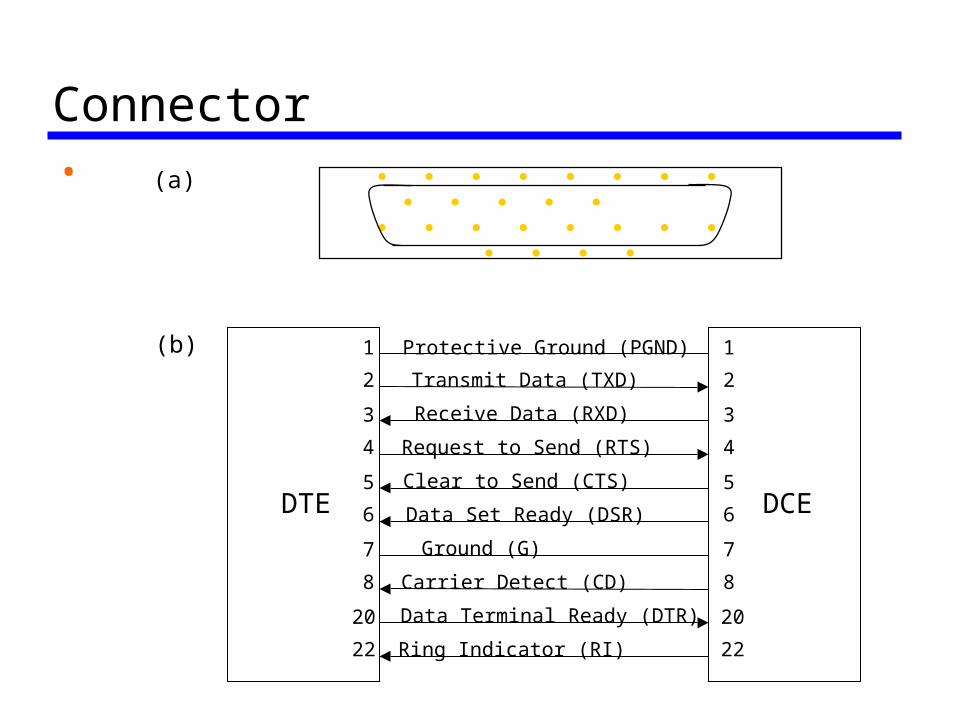
Connector•
DTE DCE
Protective Ground (PGND)
Transmit Data (TXD)
Receive Data (RXD)
Request to Send (RTS)
Clear to Send (CTS)
Data Set Ready (DSR)
Ground (G)
Carrier Detect (CD)
Data Terminal Ready (DTR)
Ring Indicator (RI)
1
2
3
4
5
6
7
8
20
22
1
2
3
4
5
6
7
8
20
22
(b)
(a)
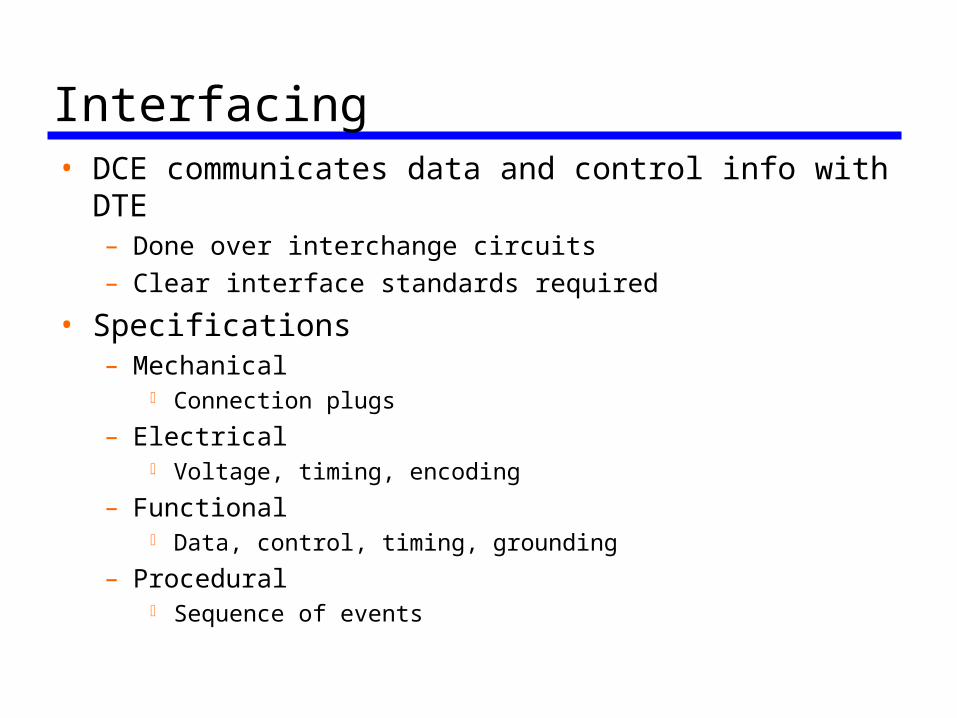
Interfacing• DCE communicates data and control info with
DTE– Done over interchange circuits– Clear interface standards required
• Specifications – Mechanical
Connection plugs
– Electrical Voltage, timing, encoding
– Functional Data, control, timing, grounding
– Procedural Sequence of events