Embed Size (px)
Citation preview
The Nuclear Decarbonization Option:Profiles of Selected Advanced Reactor Technologies
MARCH, 2012
A Clean Air Task Force Report

This document was prepared by the Clean Air Task Force for the Bipartisan Policy Center’s Energy Project. These papers are meant to inform the project’s work on nuclear energy policy. The findings and recommendations offered in these papers are those of the authors alone and not of the Clean Air Task Force, the Bipartisan Policy Center’s Energy Project, the Bipartisan Policy Center, its founders, or its board of directors.
COVER IMAGE:
(c) philipus / www.fotosearch.com.

Clean Air Task Force is a nonprofit organization dedicated to reducing atmospheric pollution through research, advocacy, and private sector collaboration.
MAIN OFFICE
18 Tremont Street
Suite 530
Boston, MA 02108
617.624.0234
www.catf.us
OTHER LOCATIONS
Beijing, China
Brunswick, ME
Carbondale, IL
Columbus, OH
Washington, DC
Houston, TX

This page intentionally left blank.

This page intentionally left blank.
Table of Contents
Introduction 1
Mike Fowler Director, Advanced Technology, Clean Air Task Force
Status of Small Modular Light Water Reactors in the US 3
Dr. Theodore U. Marston Principal, Marston Consulting
High Temperature Gas Reactors 13
Andrew C. Kadak, PhD Former Professor of the Practice, Massachusetts Institute of Technology
Breakthrough Nuclear Economics: One Possible Path – the Floride Salt Cooled High Temperature Reactor (FHR) 21
Per F. Peterson, Tommy Cisneros, Mike Laufer, Raluca Scarlat, Nicholas Zweibaum
Department of Nuclear Engineering, University of California, Berkeley
Authors’ Biographies 31


INTRODUCTION 1
WE LIVE IN A WORLD divided by many issues, but most policy-makers accept the basic premise that increasing the availability of affordable low-carbon energy would make the world healthier, wealthier, and safer. Conven-tional fuel delivery systems are strained in many regions, the global geopolitics of energy supply are fraught, and carbon dioxide emissions, despite decades of debate since Rio and Kyoto, are rising faster now than at any point in history. And still, billions remain without regular access to electricity and mobility.
Nuclear energy provides more than 40 percent of all low-carbon electricity generated in the world today. That contribution could grow, but public perceptions of safety remain a key challenge—particularly post-Fukushima—and competitive costs, as always, will be paramount. In order to assess the impact that advanced technologies could play in the development and deployment of new nuclear reactor designs, the Clean Air Task Force asked several national leaders in nuclear technology to give us their perspectives on key policy-relevant issues.
We asked Dr. Ted Marston, former Chief Technology Officer of the Electric Power Research Institute, to write for us on small, modular light water reactors (smLWRs). Dr. Andrew Kadak, former Professor of the Practice in Nuclear Engineering at the Massachusetts Institute of Technology, examines the prospects for high-temperature gas-cooled reactors (HTGRs). And Dr. Per Peterson, Chair of the Nuclear Engineering Department at University of California, Berkeley, explores the future of some fluoride molten salt reactors (called FHRs).
Their conclusions are important and offer reasons for optimism:l Small, modular light water reactors (smLWRs):
With modest development efforts, smLWRs, using fuel and systems quite similar to modern LWRs, could offer significantly enhanced safety over the existing nuclear fleet, deployment flexibility (e.g., staged invest-ment and repurposing of some existing infrastructure), and potential cost-reductions through efficiencies of factory manufacturing.
l High-temperature gas-cooled reactors (HT-GRs): HTGRs, using extremely heat-resistant, encap-sulated fuel (already demonstrated in the United States
The Nuclear Decarbonization Option:Profiles of Selected Advanced Reactor Technologies
Introduction
and elsewhere) offer the possibility of nearly meltdown-proof reactors, higher thermal efficiencies, and expand-ed uses for nuclear energy (e.g., manufacturing of zero-carbon liquid transportation fuels), as well as many of the potential deployment and manufacturing advan-tages of smLWRs.
l Fluoride salt-cooled High temperature Reac-tors (FHRs): And FHRs, using the same heat-resis-tant, encapsulated fuel as HTGRs, but with coolants of dense molten salt compounds, could retain many of the advantages of HTGRs at a greatly reduced size, offering the potential for breakthrough economics if designs prove out.
For a world struggling to reduce carbon emissions while sustaining and increasing economic growth, and under-standably concerned about the potential risks of nuclear energy, the advantages these advanced reactor designs offer could be profound. But bringing these concepts to commercial reality will require sustained development, especially for the more advanced concepts. Our hope is that these papers will help to inform the debate about how governments and the private sector should support that development.
This report does not aspire to cover the full scope of potentially important nuclear power technologies. Korean and Russian firms are developing smLWRs that could be important in some markets, and technologies that address the life-cycle of nuclear fuel and waste—including fast neutron reactors and thorium-based reactors—also could be important. More radical designs, such as the liquid fluoride thorium reactors (developed by Oak Ridge Na-tional Laboratory to use liquid fuels, rather than solid), may be able to provide even more dramatic advantages on safety, cost, and fuel cycle issues. Sub-critical reactors driven by particle accelerators may one day be able to convert low-value nuclear materials directly into energy. We will explore the potential of these technologies in future reports.
Mike FowlerDirector, Advanced Technology Clean Air Task Force

This page intentionally left blank.

MARSTON / smLWRs 3
This page intentionally left blank.Introduction to Small Modular ReactorsSmall modular reactor (SMR) is a relatively new term for the old concept of small (less than 350 MWe output) reac-tors that are principally manufactured in a shop environ-ment and shipped to the plant site for assembly. At last count, the International Atomic Energy Agency lists over 65 SMRs under development. Most of these are in early stage design, i.e. conceptual design, often called ‘paper reactors’. This white paper focuses on the type of SMR that has the most complete designs and which appears closest to deployment, at least in the US. These SMRs are cooled and moderated with light (that is, ordinary) water, similar to the operating nuclear power plant fleet in the US. In this white paper we call this type of SMR the small, modular, light water reactor (smLWR).
Potential Benefits of smLWRsEnergy demand and economic benefits of smLWRs Since 2008, there has been a growing interest in the US in the development and deployment of small modular light water reactors (smLWRs). There are a number of reasons for this interest. For the US utilities, these include:l US utilities need new baseload generation capacity due
to insufficient reserve margins in many of the North America Electricity Reliability Corporation (NERC) regions.
l Most US electric utilities cannot afford to take the fi-nancial risk of building a large advanced light water reactor (ALWR) because the project represents a ma-jor portion of the entire capitalization of the average nuclear utility.
l Most US electric utilities cannot accommodate a 1300MWe or greater block of new generation in their service territories. Additionally, they wish not to put that much generation on ‘one shaft’, i.e. too great a gen-eration risk if the plant is unavailable.
Status of Small Modular Light Water Reactors in the US
l Smaller, older coal-fired power plants in US face in-creasing pressure from environmental requirements, including potential carbon constraints. Some estimate as much as 45GWe of old coal plants will be closed in the next 5 to 10 years.
As a result of the utility interest in smLWRs, there is an increasing interest from the traditional and non-tradition-al US nuclear plant suppliers. NuScale Power, a start-up company in Oregon, was the first firm to seriously pursue smLWR business and associated licensing issues. Babcock and Wilcox, a 150 year old boiler manufacturer, soon fol-lowed. More recently, Westinghouse has entered the competition. The primary reason for their interest is the potential nuclear plant sales, but there are a number of ancillary factors. From a public policy perspective these include:l The smLWR could help restore the US leadership
in nuclear energy l Provides for US manufacturing jobsl Helps restore the US nuclear supply chain
infrastructurel Opportunity to sell US shop-assembled modules
overseasl Revise (improve) the timeliness of the US regulatory
process for new technologyl Increased profitability from exploiting the ‘learning
curve’ for smLWRs
Both the House of Representatives and the Senate have prepared bills to support the development and deployment of small modular reactors. The motivation behind the Congressional bills is to stimulate job growth and the economy. Estimates of the economic benefit1 of one small
THEODORE U. MARSTON, PHD.
Principal, Marston Consulting
Note: Prior to the Fukushima accident, it was thought that the
smLWRs could replace retired coal-fired generation in key locations.
The impact of the accident on the acceptability of nuclear power to
the public makes this option more uncertain.

4 MARSTON / smLWRs
smLWR plant include:l 7000 jobsl $1.3 B in salesl $0.63B in value-addl $0.4B in earningsl $35M in business taxes
President Obama’s administration has issued broad na-tional emission reduction goals and specific guidance for federal installations; these are:1) National greenhouse gas (CO2) emissions must be
reduced by 83% below 2005 by 2050, 42% by 2035 and 30% by 2025.2
2) All federal installations must reduce their greenhouse gas (CO2) emissions by 28% by 2020.3
Deployment of smLWRs at DOE and DoD facilities, particularly national laboratories would support these emission reduction goals for federal facilities.
Safety Benefits for smLWRs
The smLWR concept has a number of attractive features from the perspective of power plant safety and protection of the public health and safety from radioactive releases. This section presents some generic considerations that set the smLWR apart from traditional LWR designs. This is not to say that the current designs are not safe. Indus-try efforts at continuous improvement, compliance with NRC regulations, and the passing of countless inspections by the NRC assure the safety of the US LWR fleet. These features include:
l Greater chance for ‘inherent safety’ – the general de-signs incorporate concepts of natural circulation of the primary system following reactor scram,4 cooling wa-ter provided from large tanks or reservoirs using grav-ity, decay heat rejection systems that are mostly inside the reactor containment structure, no need for grid-supplied or on-site emergency power for extended periods of time, large battery capacities to run instru-mentation and control (I&C) systems and limited valve operations, digital I&C systems (which provide more resilient reactor control than analog), and extended time for operators to develop robust recovery strate-gies. These attributes are similar to those of the larg-er, passive advanced light water reactors (ALWRs), such as the Westinghouse AP1000.
l Smaller source term5 for severe accidents (e.g., those that can lead to core damage) and more effective de-cay heat removal – these reduce the likelihood of a core damage event and reduce the amount of radioactive release in the low probability event of a core damage
event. The smLWRs have independence of the mod-ules in a multi-module plant. The containments are located below grade and are designed to sustain high internal pressures and protect equipment from exter-nal threats.
l Integral designs (described in more detail below) sig-nificantly reduce risks of large break loss-of-coolant accidents (LOCAs) – there are no large main coolant pipes to break. The largest credible break size is a few square inches. Reactor pressure vessel (RPV) vessel penetrations are limited by design. All reactor coolant pumps (RCPs) use canned rotor pumps (which have no seals that could result in leaks).
l Larger primary inventory basis and pressurizer – The primary system cooling water inventory is roughly three times that of conventional LWRs on a MWth basis. The relative pressurizer volume of smLWRs is also much larger, which improves ability to maneuver the reactor through some transients.
l Vessel layout facilitates natural convection – the smL-WR vessels are very tall and small diameter in com-parison with conventional LWRs. The entire secondary system is well above the core in elevation. One of the smLWR designs run normally on natural circulation. Those with RCPs are designed to transition smoothly to natural circulation, if the RCPs fail to operate.
l Below grade containment has safety and security ad-vantages – All of the US design smLWRs have contain-ments located below grade, which make aircraft impact an incredible event. The used fuel pools are similarly located below grade and some are inside of contain-ment. Flooding in below grade spaces must be consid-ered carefully in the design of the smLWRs to assure the protection of vital equipment if the plant is sub-jected to flooding conditions.
l All of the smLWRs utilize a probabilistic safety analy-sis in the design process to assure the likelihood of core damage frequency (CDF) is as low as practical. The es-timated CDFs and radioactive release frequencies for the smLWRs are projected to be equal to or lower than the ALWRs, which are substantially below those of the operating light water reactors.
Status of smLWR DevelopmentThree smLWR designs appear to have the greatest poten-tial for commercial success in the 2020 timeframe. The designs are integral, pressurized water reactors (PWRs), i.e. designs in which the major nuclear steam supply sys-tem (NSSS) components, including reactor and core, steam

MARSTON / smLWRs 5
generators, pressurizer and pumps (if part of the design), are housed in a single pressure vessel. The original integral PWR was designed to power the German commercial ship, N.S. Otto Hahn, commissioned in 1968, which sailed without incident for over one million kilometers. The ship was converted to conventional power in 1979 for eco-nomic reasons.
The three designs selected are:l NuScale reactor (45 MWe, natural circulation) under
development by NuScale Power, Inc.,l mPower reactor (180 MWe, forced circulation) under
development by the team led by the Babcock & Wilcox Company,
l SMR (>225 MWe, forced circulation) under develop-ment by Westinghouse Electric Company LLC.
We briefly summarize each design, provide a figure showing the overall plant, the containment structure and the integral reactor pressure vessel, and identify the com-mercialization strategy. Following the individual smLWR descriptions, a table compares and contrasts the three designs. Each of the designs uses a shortened length vari-ant of standard commercial 17X17 PWR fuel. All of the three smLWRs are designed for 60 years of operation.
NuScale
NuScale Power, Inc., originally a privately held company6 in Corvallis, Oregon USA, is designing and commercial-izing, a modular, 45 MWe Pressurized Water Reactor. Each NuScale module has its own combined containment vessel and reactor system, and its own designated turbine-generator set. NuScale power plants are scalable, allowing for a single facility to have just one or up to 12 units. In a multi-module plant, one unit can be taken out of service without affecting the operation of the others. The reference NuScale plant has 12 modules and generates 540 MWe.
Each NuScale plant component is modular and is de-signed for fabrication in a number of existing facilities in the USA and around the world. In theory, the construction should be less complex, lead times shorter, and costs more predictable and controllable. The NuScale containment containing the reactor pressure vessel measures approxi-mately 60 feet in length and 14 feet in diameter. All com-ponents are transportable by barge, truck or rail.
The NuScale design requires no operator actions in the first 72 hours after plant shutdown. The ultimate heat sink is a pool of water internal to the reactor building which sits below grade. This pool is sized to accept decay heat from all modules without boiling for the first 72 hours. If pool or reactor cooling is not restored or other sources of make-up to the pool are not provided the reactor pool will slowly boil off over time allowing the decay heat load to subside. By the time the pool inventory is exhausted, decay heat will have dropped to a point that air cooling on the shell of the containment is sufficient to maintain the reactor cores cooled and covered.
Each module has its own independent turbine genera-tor set that is also small enough to be delivered as a complete, modular package. In addition to the modular-ity of the design, the plant will be constructed using modular construction techniques.
Favorable characteristics of the NuScale design include:l Small size of the Reactor Buildingl Significant portion of the building underground l Limited access into reactor buildingl Passive safety systemsl Limited vital equipmentl Ultimate heat sink internal7 to the reactor buildingl Smaller fission product inventory per reactorl Use of remote and automated technologiesl Risk informed approach to design
FIGURE 1 Shows the reference 540 MWe,
12 Module NuScale Plant with the Details of the
Containment and Pressure Vessel Structure
6 MARSTON / smLWRs
mPower
The Babcock & Wilcox (B&W) Company builds small light water reactors for the US Navy. Originally, their com-mercial smLWR was a modular, 50 MWe, natural circula-tion, pressurized water reactor planned for emergency power use by the US Air Force as part of their Small Military Power Plant (SMPP) program. This reactor was called the B&W Gem50. In 2009, B&W uprated the Gen50 to 125 MWe using forced circulation with internal pumps and in 2011 the power increased to 180 MWe.
The new reactor concept is called the B&W mPower reactor. Some of the key mPower features include all forg-ings capable of being fabricated in the US; transportable by rail; use of “proven” technology, wherever possible; and licensing features that the NRC would find “comfort-able”. The technology which is unproven will be tested extensively. The internal control rod drives , required by the design, are the novel principal technology in the mPower design. B&W formed a joint venture LLC with Bechtel Power in 2010
The mPower team began pre-application interactions with the US Nuclear Regulatory Commission (USNRC) in July 2009. Design certification application for the mPow-er design is expected for either the 4th quarter of CY 2012 or 1st quarter of CY 2013.
The lead plant project for the mPower design is a joint mPower – Tennessee Valley Authority (TVA) proposed 2 unit power plant on the TVA Clinch River Site. This pro-posed station will provide emission-free electricity to the
Oak Ridge National Laboratory (ORNL) to help the labo-ratory meet the previously discussed CO2 reduction targets mandated by the Obama Administration.
The mPower safety approach incorporates:l Passive safety
– No safety related emergency diesel generators– No core uncovering during design basis accident
conditionsl 2 trains of emergency core cooling systems (ECCS)l Natural circulation assured when the RCPs are
shutdownl Multi-level Digital I&C systems with diverse analog
shutdown systeml In containment reactor water storage tankl Full pressure ECCS heat exchanger inside of
containment
B&W is:l One of the last major nuclear component manufactur-
ers left in the US. In the 1970s, there were five major component manufacturers
l The major nuclear heavy component supplier to the US Navy
l Capable to make the entire integral mPower vessel in house.
l The mPower vessel is designed to be rail-transportable throughout the US.
The outstanding testing to be completed includes:l Components
– Canned rotor (sealess) reactor coolant pumps– Control rod drive mechanisms (CRDMs)
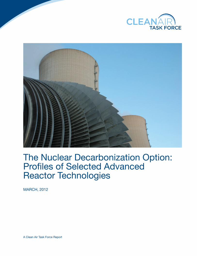
FIGURE 2 Illustrates the mPower 360
MWe Reference Plant with 2 Modules,
Below Grade Containment Details
and Integral Pressure Vessel

MARSTON / smLWRs 7
– Fuel mechanical testing8 – CRDM/fuel integrated test– Fuel critical heat flux – Emergency high pressure condenser
l B&W has constructed an integrated systems testing facility in Bedford, VA. Among other things, the facility will investigate:– Heat transfer phenomena– Steam generators performance– Loss of coolant accident response– Pressurizer performance– Reactor control
Westinghouse Small Modular Reactor
Westinghouse, a wholly owned subsidiary of Toshiba, announced in February of 2011, they would be developing a 225MWe small modular reactor. All primary components of the Westinghouse SMR, a 250 MWe integral pressurized water reactor, are located in the reactor vessel. It features passive safety systems and a reduced number of compo-nents compared to other reactor designs. Many of the reactor’s parts can be manufactured in factories off-site and delivered by truck or rail to the plant site.
The Small Modular Reactor enables Westinghouse to integrate all that they know about operating nuclear plants,
designing and licensing plants, and passive safety into a small design that will provide additional nuclear power options for their owner/operator customers. Much of the Westinghouse SMR’s design draws from the company’s AP600 and AP1000 designs.
Some of the safety and security features of the West-inghouse SMR include: l In the event of a station blackout, the Westinghouse
SMR is designed to shut down automatically, requir-ing no intervention for seven days, using gravity and natural cooling.
l Spent fuel pool is located below grade and contains heavily reinforced concrete structures lined with steel.
l Spent fuel will remain covered with gravity flow of wa-ter from safety related Decay Heat Removal Tanks for a period of seven days
l Containment designed for protection against seismic events, natural disasters, and aircraft impact.
Westinghouse SMR design certification document (DCD) package is on-schedule for NRC submittal in 2012. Com-ponent and system tests and planning are on schedule. The testing program underway for the CRDMs should confirm the applicability of the proven AP600 and AP1000 CRDMs in the Westinghouse SMR environment.
FIGURE 3 Illustrates the Reference Westinghouse 225 MWe SMR Plant with one module, Details of the Below Grade
Containment and Integral Pressure Vessel

8 MARSTON / smLWRs
Challenges to CommercializationThe smLWRs have a number of challenges to successful commercialization. These include regulatory and eco-nomic challenges and overcoming the negative public reaction to the Fukushima accident. There are a number of regulatory issues related to the licensing and deploy-ment of smLWRs in spite of the fact that the current li-censing base is built around light water reactors. The NRC regulations are designed for large plants. All of the PWRs in the US are non-integral, i.e. separate reactor pressure vessel, steam generators, reactor coolant pumps and pres-surizers. Some of the major issues under consideration by the US NRC and the principal contentions are pre-sented below:l Nuclear insurance – Price Anderson - The premium
payments paid annually by the owner/operators for Price Anderson liability insurance are based on the number of reactors owned. The premium is based on large LWRs. It is believed that the second party liabil-ity incurred by smLWRs are significantly less than for plants with core thermal ratings as 30 times greater. Proposals to amend the premium structure to account for core power output are under development.
l Annual fees – The NRC assesses their annual fees to the licensees on the basis of the number of plants. The NRC has to collect 90% of their annual operating bud-get from direct fees charged for review, licensing and inspection or indirect fees charged to each nuclear pow-er plant. In 2010, each nuclear plant was charged $4,719,000 regardless of the power output. It is felt that each smLWR should not be charged the same amount as the larger plants. A sliding scale is proposed to deal with the size discrepancies.
l Staffing – Current control room staffing requirements are based on large reactors with fully analog control room technology. The control rooms and I&C systems for the smLWRs should be fully digital, possibly with a separate analog system to provide redundancy and diversity in the shutdown of the smLWRs. The inher-ent safety of the new smLWR designs in conjunction with the fully digital control systems with a high de-gree of automation should permit the safe operation of the smLWRs without the tradition one control team for each reactor, used in the existing plants. Alterna-tive staffing requirements are under discussion.
Summary Table of smLWRs
The following summary table compares and contrasts the three smLWR designs. The information in the table is pro-vided by the NSSS designers. The decay heat removal time listed is the minimum time without any intervention. One design can theoretically go indefinitely with no intervention. The others require minimal intervention, such as filling of unpressurized tanks and pools, to maintain adequate decay heat removal for an indefinite period of time.
smLWR Summary Table9

MARSTON / smLWRs 9
l Security – Security requirements for US LWRs have increased substantially since the terrorist events of 11 Sept 2001. The requirements are based on new threats and the ability for existing reactors to respond to those threats. The smLWR designs include security in the design and have taken major steps to reduce the secu-rity needs. For example, the entire nuclear steam sup-ply system (NSSS), spent fuel pool and containment for all designs are located below grade. The access to control and radioactive material areas is significantly reduced over the existing plants. State of the art secu-rity and intrusion detection systems are part of the de-sign. Therefore, it is believed that adequate security of a smLWR can be maintained with simplified security requirements. Proposed simplifications are under de-velopment for smLWRs.
l Emergency planning – size of emergency planning zones – The emergency planning and the zone of evac-uation for US plants is based on the existing fleet. The smLWRs are significantly different in terms of source term in the case of a core melt event. The smLWR core damage frequencies are orders of magnitude lower than what is required in the NRC regulations.10 The contain-ments are located below grade and the long term cool-ing needs of a beyond design basis core damage event are much less. For these reasons, the industry believes the current emergency planning zones and notification requirements can be greatly simplified and still protect the health and safety of the public. Proposed simplifi-cations of emergency planning for the smLWRs are currently under development. Such simplification is required to locate a smLWR near regions of high pop-ulations, such as those surrounding the existing coal plants that will likely be shut down. This simplification will be a major challenge in light of the 2011 Fukushi-ma accident in Japan.
Regulatory challenges could make smLWRs non-competitive. If the licensing of smLWRs become pro-tracted affairs, the attractiveness of such small plants will vanish. The best hope for smLWRs to be competitive lies in the assumption that they can be licensed, built and commissioned quickly.
The primary economic challenge to the commercializa-tion of smLWRs is whether the electricity production costs are (1) affordable and (2) competitive with other forms of generation. With regard to affordability, smLWRs offer potential optionality to the US electric utilities, when the only real options for large generation additions are gas fired, coal fired or large nuclear plants. SmLWRs, being smaller and modular, potentially offer a more manageable
nuclear option. SmLWRs are more ‘affordable’, i.e. less of a fiscal risk. They can be deployed in much smaller incre-ments, matching the utilities’ load growths better and reduce the ‘single shaft’ generation risk to an acceptable level.
Competing with other forms of electricity generation is a much greater challenge today. Vast amounts of natu-ral gas are being discovered across the US in so-called tight gas (shale) deposits, resulting in cheap and abundant natural gas. The current spot market price of natural gas is less than $3.00/MMBTU. Carbon restraints (taxes or credits), which would improve the competitiveness of smLWRs, appear unlikely to arise in the near future. However it is expected that carbon emissions from large stationary sources will be reduced systematically over time one way or another, and US utilities are very interested in reducing their ‘carbon footprints’. If the economics of the smLWRs are what some of the designs claim, there is a real chance to compete with natural gas fired plants, particularly when carbon constraints are in place. The cost competitiveness of smLWR depend heavily on achieving the following opportunities:l Streamline design and manufacturing are necessary to
offset the economies of scale of other generation op-tions, particularly nuclear plants. ALWRs are becom-ing larger and larger due to the economies of scale. The only prospect to reverse this effect for the smaller smL-WRs is to streamline the shop fabrication of the NSSS and other modules, ship them to the site and install them rapidly. The requisite quality standards must be maintained throughout the entire process.
l Modularity of the smLWRs provides the opportunity to transform how we design, build, operate and decom-mission nuclear power plants.
l Reduce construction time by modularization and con-struction efficiencies
l SMRs do not require loan guarantees. This sets the smLWR apart from the larger ALWR, which currently benefit from federal loan guarantees, especially for reg-ulated utilities. Experience shows the loan guarantee process to be a protracted and expensive affair, requir-ing the expenditure of significant political and fiscal capital.
How the impacts of the Fukushima accident affect smLWR development and deployment is unclear. The passive nature of the safety systems and the reduced need for AC power following shutdown should be positive at-tributes. Likewise, the depth of the containment should mitigate certain security concerns, but may raise flooding concerns. However, the idea of locating a number, up to

10 MARSTON / smLWRs
twelve, of smLWRs at a single plant site may become a liability in the eyes of the public. The sequential failure of the Fukushima reactors followed by the hydrogen explo-sions will be long lasting memories for the public. It may be difficult to convince the public that more reactors at a site is safe, in spite of the fact that the single reactor fail-ure source term is much smaller than current reactors and that there is little chance for system interaction in the new designs.
US Market Potential for smLWRsThe potential smLWR market in the US is quite large, with three primary opportunities for deployment. The nearest term opportunity is to build the initial plants to provide low emission electricity to DOE and DoD facilities that are subject to the Executive Order. This opportunity will be part of the current DOE SMR Program. The second opportunity for smLWR deployment is to provide baseload (or near baseload) generation capacity resulting from general load growth. Baseload generation has not been installed to any degree since the 1970s and 1980s in the US. Most of the recent generation additions have been combined cycle turbines fueled by natural gas. The net demand for the US will grow by 30% in the next 20 years, however. There are renewable portfolio standards in 30 states in the US, so some of this growth will be met with renewable generation, but others, like Ohio, have clean energy standards which include the traditional renewables and other forms of non-emitting generation, such as nuclear plants and large dams. Even with renewables and some gas, a role for nuclear could emerge due to general demand growth.
The third opportunity is replacement of existing fossil baseload generation. The DOE estimates that 75 GWe of old coal (operating life > 35 years) could be retired by 2025. In addition to the old coal plants, there is almost 20GWe of old, inefficient natural gas and oil-fired boilers in the US that are over 50 years old. The potential smLWR replacement percentage of this retiring generation may be as high as 10% or about 10 GWe of deployment.
Research, Development and Demonstration NeedsThe US Department of Energy has adopted the small modular reactor as one of their keystone programs. One of the major elements of the DOE SMR Program is support of the design and licensing of two smLWRs with up to $425M. The designs will be selected through a competitive
process initiated with a funding opportunity announce-ment (FOA). A draft of the FOA is out for comment and the final FOA is expected to issue in 2Q 2012. In addition to the FOA on smLWR design and certification, the DOE expects to fund R&D related to smLWRs on the following subjects:l Regulatory issuesl Safety analysis, particularly from a probabilistic safe-
ty analysis point of viewl Fabrication efficiency improvementsl Digital instrumentation and control.
Each of the smLWR designers has an extensive test program to meet the regulatory and reliability needs of the new design.
ConclusionsSmLWRs offer a potentially attractive nuclear option to the US electricity new build landscape that will most likely be dominated by natural gas. However, the actual deployment of smLWRs will depend on two factors. The first factor is the simplification of emergency planning zones (EPZs) for the smLWRs by the NRC and the need for public acceptance of small, very safe nuclear plants near to population centers. This is a necessary, but not sufficient condition for success deployment. The smLWRs must make economic sense to the owner/operators. They must be affordable, financeable and the levelized cost of electricity must be competitive with other low or no emis-sion generation technologies.
Footnotes 1 Solan, David, Economic Impacts of Small Modular Reactors: Consider-
ations and Recent Events, Center for Advanced Energy Studies, The Idaho National Laboratory, Platts 2nd Annual Small Modular Reactors Conference, May 2011, Washington, DC.
2 White House November 2009.
3 White House October 5, 2009. Executive Order 13514.
4 A reactor SCRAM is a sudden, complete, shutdown of the reactor fis-sion power production by the insertion of control rods or other mecha-nisms.
5 The ‘source term’ is the amount of radioactivity that potentially could be released to the environment following an accident.
6 The Fluor Corporation obtained a majority position in NuScale Power, LLC in October 2011.
7 The ultimate heat sink is the final cooling reservoir or medium for decay heat from a shutdown reactor.
8 Although similar to fuel for conventional LWRs in many ways, some structural and mechanical differences necessitated by the geometry of this reactor core necessitate new testing and validation.

MARSTON / smLWRs 11
9 Table Notes: NA – not available, FOAK – first of a kind, NOAK – nth of a kind, Passive safety – no active components required for emergency core cooling, No&L – number and active length of fuel assemblies, OTSG – once through steam generator, Part 52 – 10CFRPart52 (one-step licensing process), Part 50 – 10CFRPart50 (conventional licensing process), Hybrid 50/52 – First plant licensed under Part50, followed by certification of design under Part52, vacuum – containment is operated at sub-atmospheric pressures to improve insulation and response to pressurization, rail ship – major components shippable by rail.
10 For an example of a preliminary analysis of these issues, see, Probabi-listic Risk Assessment of NuScale Reactor During the Design Phase, Welter et al, 2009.

This page intentionally left blank.

KADAK / HTGR 13
This page intentionally left blank.IntroductionHigh temperature gas reactors (HTGR) are gaining in-creasing interest globally due to their high thermal effi-ciencies for electricity production, high temperatures for process heat applications, and inherent safety. The Fuku-shima nuclear accident in Japan has also renewed interest in more accident tolerant1 reactors. Germany was the historic leader in the development and application of HTGRs, centered around their Jeulich Research Institute, which used pebble bed reactor technology.2 In the United States, General Atomics was the leader in HTGR technol-ogy using helium cooled prismatic-block reactors, sev-eral of which were built in the 1960s and 1970s. Japan has an operating prismatic-block helium cooled-research reactor in operation since 1999, with a goal of demonstrat-ing hydrogen production, and South Africa was about to build a 165 Mwe direct cycle pebble bed reactor (PBMR) until the economy of the country and rising costs forced its cancelation. More recently, China has taken on sig-nificant leadership in some aspects of HTGR technology.
In the United States, Exelon, the largest nuclear gener-ating company, was a 10% owner of the South African pebble bed project and was planning to build the US ver-sion of the PBMR until low natural gas prices and man-agement changes within the company resulted in Exelon pulling out of the project. Exelon went as far as submitting pre-licensing white papers to the Nuclear Regulatory Commission before cancelling the project.3 The 2005 Energy Policy Act mandated the construction of the Next Generation Nuclear Plant (NGNP) by 2021 which was to be a high temperature gas reactor to provide heat for hydrogen production at the Idaho National Laboratory. Three competing design teams made up of such companies as Westinghouse Electric Company, General Atomics, AREVA and Shaw Engineering representing both pebble and prismatic reactors were preparing conceptual designs for the NGNP. The NGNP industry alliance4 recently an-
ANDREW C. KADAK, PH.D.
Former Professor of the Practice
Massachusetts Institute of Technology
High Temperature Gas Reactors
nounced that they have decided to support the construc-tion of the AREVA prismatic version of the NGNP for process heat production since Westinghouse (PBMR) and General Atomics withdrew from the competition. Unfor-tunately, this project was recently relegated to a research and development project instead of the construction of a demonstration plant by the Department of Energy.
More positively, China has taken the lead using pebble bed reactor technology having an operational 10 Mwth research reactor in operation since 2000 at Tsinghua University’s Institute of New and Nuclear Energy Technol-ogy (INET) near Beijing. Construction of a full scale 200 Mwe electric generating station using this technology (High Temperature gas cooled Reactor – Pebble-bed Module – HTR-PM) for Huaneng Group is underway near Shidao in Shandong Province. The Chinese have been developing the high temperature pebble bed technology since the early 1990s. The HTR-10 reactor has been used to test fundamental helium technology systems including valves, online refueling systems, fuel manufacture and qualification in Russian test reactors, steam generator design and overall operations. This reactor ran several significant tests including loss of helium flow, turbine trips, loss of offsite power supply, and helium blower trips without insertion of shutdown rods. The Chinese have used this experience to design their full scale prototype power reactor. In addition they have built impressive test facilities at their research facility outside of Beijing to perform testing of key components of the HTR- PM dem-onstration reactor. They have built a 10 Mw helium test loop, a scaled version of their helical once through steam generator to verify performance of the design; a full scope test facility of the fuel handling system; and test facilities to confirm the design of their control rod drive mechanism and shutdown system. As these facilities demonstrate, Tsinghua University’s Institute of Nuclear Energy Tech-nology has taken the lead in high temperature reactor development.
14 KADAK / HTGR
In terms of licensing, the HTR-PM has passed the licens-ing review with over 2000 questions that were raised by the Chinese regulatory authorities prior to the issuance of a construction permit. The Chinese National Nuclear Safety Administration has licensed the French 1000 Mwe PWR, the Russian VVER, Sodium Cooled Fast Reactor, the Westinghouse AP-1000 and the French EPR in the past and is viewed as a qualified licensing authority sup-ported by universities and science and engineering insti-tutes in China. China’s regulations are patterned after US high level regulations but are less prescriptive.
The promise of high temperature reactors has always been safety and the ability of producing heat at between 750 C to 950 C which are temperatures impossible to at-tain for light water reactors. This high temperature is possible due to the use of silicon carbide coated fuel particles containing minute amounts of uranium, graph-ite and using the inert gas, helium, as a coolant. This high temperature offers opportunities not only for 50% more efficient electric production but also for replacing CO2-emitting fossil fuels such as coal, oil and natural gas in the production of high quality steam. The temperatures produced are high enough for chemical production of hydrogen5, and for such activities as oil sands production (avoiding the use of coal or natural gas to extract the oil), oil refining, conversion of coal to synthetic fuels, and extraction of oil from shale. While these latter missions may seem counter to reducing CO2 emissions, the need for fossil fuels for transportation remain and the use of high temperature gas reactors to avoid fossil emissions for their extraction could be an important avoidance strategy.
Technology BasicsGas cooled reactors are not new. The earliest demonstra-tion of high-temperature, helium-cooled reactors was the Dragon plant in the UK which started operation in 1964. The first gas cooled reactors were used to produce steam in a Rankine cycle, as a conventional light water reactor might produce, but at temperatures in the 700 C range (e.g., at the Peach Bottom and Fort St. Vrain reactors in the US). More recent designs which go to higher tem-peratures use a Brayton cycle with gas turbines to produce electricity. The gas turbine cycle allows for even higher thermal efficiencies of up to 50%, reducing cooling needs by 50%.
For electric power production numerous options exist: a direct cycle takes the hot helium directly into a gas turbine; an indirect cycle which takes the heat from the reactor to an intermediate heat exchanger to make steam or another gas system to power gas turbines. This inter-mediate heat exchanger allows for a multiplicity of end uses for the energy of the reactor produces making the reactor essentially a universal heat engine.
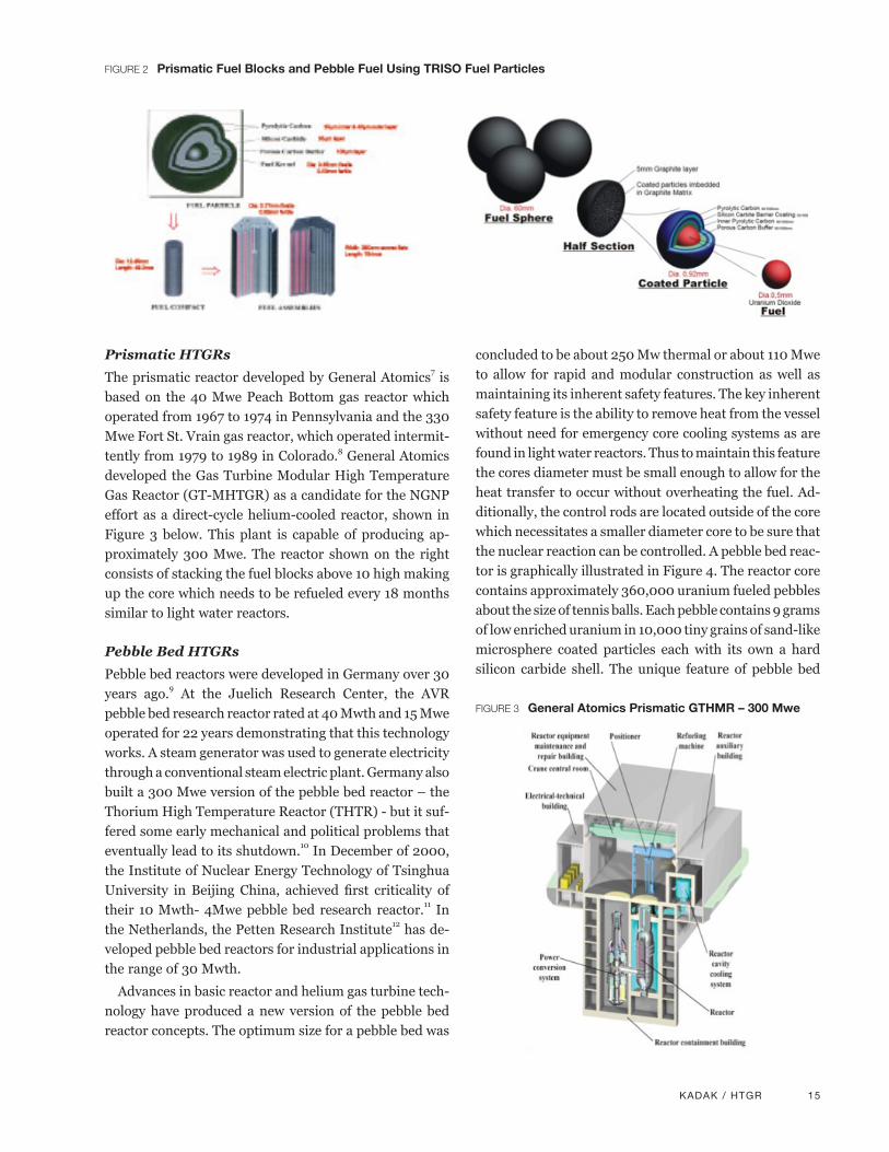
There are two major types of high temperature gas reac-tors: Prismatic-block, and pebble bed. Both use the same type of fuel form, however – poppy seed-sized kernels of uranium coated with several thin layers of protective material including silicon carbide and graphite, called “TRISO.”6 These tiny particles are shaped into a pebble with additional graphite or, alternatively, a chalk-sized compact which is inserted into a graphite block as shown on Figure 2. In the pebble form each pebble, which is ap-proximately the size of a tennis ball, contains 10,000 of the TRISO particles.
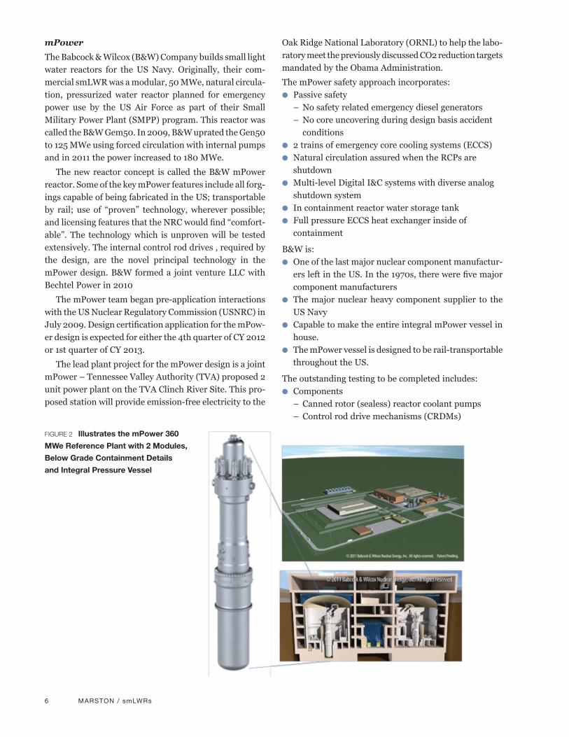
FIGURE 1 Sites of HTR-10 on the left, and New HTR-PM Construction in China on the right
KADAK / HTGR 15
Prismatic HTGRs
The prismatic reactor developed by General Atomics7 is based on the 40 Mwe Peach Bottom gas reactor which operated from 1967 to 1974 in Pennsylvania and the 330 Mwe Fort St. Vrain gas reactor, which operated intermit-tently from 1979 to 1989 in Colorado.8 General Atomics developed the Gas Turbine Modular High Temperature Gas Reactor (GT-MHTGR) as a candidate for the NGNP effort as a direct-cycle helium-cooled reactor, shown in Figure 3 below. This plant is capable of producing ap-proximately 300 Mwe. The reactor shown on the right consists of stacking the fuel blocks above 10 high making up the core which needs to be refueled every 18 months similar to light water reactors.
Pebble Bed HTGRs
Pebble bed reactors were developed in Germany over 30 years ago.9 At the Juelich Research Center, the AVR pebble bed research reactor rated at 40 Mwth and 15 Mwe operated for 22 years demonstrating that this technology works. A steam generator was used to generate electricity through a conventional steam electric plant. Germany also built a 300 Mwe version of the pebble bed reactor – the Thorium High Temperature Reactor (THTR) - but it suf-fered some early mechanical and political problems that eventually lead to its shutdown.10 In December of 2000, the Institute of Nuclear Energy Technology of Tsinghua University in Beijing China, achieved first criticality of their 10 Mwth- 4Mwe pebble bed research reactor.11 In the Netherlands, the Petten Research Institute12 has de-veloped pebble bed reactors for industrial applications in the range of 30 Mwth.
Advances in basic reactor and helium gas turbine tech-nology have produced a new version of the pebble bed reactor concepts. The optimum size for a pebble bed was
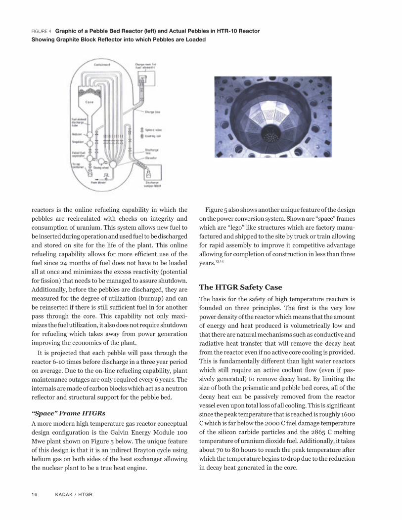
concluded to be about 250 Mw thermal or about 110 Mwe to allow for rapid and modular construction as well as maintaining its inherent safety features. The key inherent safety feature is the ability to remove heat from the vessel without need for emergency core cooling systems as are found in light water reactors. Thus to maintain this feature the cores diameter must be small enough to allow for the heat transfer to occur without overheating the fuel. Ad-ditionally, the control rods are located outside of the core which necessitates a smaller diameter core to be sure that the nuclear reaction can be controlled. A pebble bed reac-tor is graphically illustrated in Figure 4. The reactor core contains approximately 360,000 uranium fueled pebbles about the size of tennis balls. Each pebble contains 9 grams of low enriched uranium in 10,000 tiny grains of sand-like microsphere coated particles each with its own a hard silicon carbide shell. The unique feature of pebble bed
FIGURE 2 Prismatic Fuel Blocks and Pebble Fuel Using TRISO Fuel Particles
FIGURE 3 General Atomics Prismatic GTHMR – 300 Mwe
16 KADAK / HTGR
reactors is the online refueling capability in which the pebbles are recirculated with checks on integrity and consumption of uranium. This system allows new fuel to be inserted during operation and used fuel to be discharged and stored on site for the life of the plant. This online refueling capability allows for more efficient use of the fuel since 24 months of fuel does not have to be loaded all at once and minimizes the excess reactivity (potential for fission) that needs to be managed to assure shutdown. Additionally, before the pebbles are discharged, they are measured for the degree of utilization (burnup) and can be reinserted if there is still sufficient fuel in for another pass through the core. This capability not only maxi-mizes the fuel utilization, it also does not require shutdown for refueling which takes away from power generation improving the economics of the plant.
It is projected that each pebble will pass through the reactor 6-10 times before discharge in a three year period on average. Due to the on-line refueling capability, plant maintenance outages are only required every 6 years. The internals are made of carbon blocks which act as a neutron reflector and structural support for the pebble bed.
“Space” Frame HTGRs
A more modern high temperature gas reactor conceptual design configuration is the Galvin Energy Module 100 Mwe plant shown on Figure 5 below. The unique feature of this design is that it is an indirect Brayton cycle using helium gas on both sides of the heat exchanger allowing the nuclear plant to be a true heat engine.
Figure 5 also shows another unique feature of the design on the power conversion system. Shown are “space” frames which are “lego” like structures which are factory manu-factured and shipped to the site by truck or train allowing for rapid assembly to improve it competitive advantage allowing for completion of construction in less than three years.13,14
The HTGR Safety CaseThe basis for the safety of high temperature reactors is founded on three principles. The first is the very low power density of the reactor which means that the amount of energy and heat produced is volumetrically low and that there are natural mechanisms such as conductive and radiative heat transfer that will remove the decay heat from the reactor even if no active core cooling is provided. This is fundamentally different than light water reactors which still require an active coolant flow (even if pas-sively generated) to remove decay heat. By limiting the size of both the prismatic and pebble bed cores, all of the decay heat can be passively removed from the reactor vessel even upon total loss of all cooling. This is significant since the peak temperature that is reached is roughly 1600 C which is far below the 2000 C fuel damage temperature of the silicon carbide particles and the 2865 C melting temperature of uranium dioxide fuel. Additionally, it takes about 70 to 80 hours to reach the peak temperature after which the temperature begins to drop due to the reduction in decay heat generated in the core.
FIGURE 4 Graphic of a Pebble Bed Reactor (left) and Actual Pebbles in HTR-10 Reactor
Showing Graphite Block Reflector into which Pebbles are Loaded

KADAK / HTGR 17
The long time it takes to heat up the core is due to the large heat capacity of the graphite blocks that may up the reflector. The conclusion that decay heat cannot melt an HTGR core is supported by tests and analysis performed in Germany, Japan, China, South Africa and the US. Both the low power density and the relatively small size of the core allow for the unique safety of this reactor technology.
The second key principle is that the reactor naturally shuts itself down as the temperature goes up (due to im-pact of the temperature on core reactivity). This feature (shutting down upon increase is temperature) is a feature which light water reactors do not possess and prevents the type of accident that occurred at the Chernobyl nucle-ar plant. A demonstration of an intrinsic shutdown of an HTGR reactor took place at the HTR-10 reactor near Beijing before an expert panel from the International Atomic Energy Agency15 in 2004.
The third principle is that the silicon carbide - which forms the tiny containment for each of the 10,000 “TRISO” fuel particles in a pebble – can retain its fission products under all anticipated reactor conditions, provided adequate standards have been met in its manufacture. In tests performed to date on fuel reliability, it has been shown that micospheres can be routinely manufactured with initial defects of less than 1 in 10,000. In safety analyses, it is assumed therefore that 1 in 10,000 of these micro-spheres has a defect that would release the fission products into the coolant. Since the amount of fuel in each particle is very small, only 0.0007 grams, then even with this as-sumption and under accident conditions, the release from the core would be so low that no offsite emergency plan would be required. In essence, it is recognized that the
fuel cannot be made perfectly, but the plant is still safe because is has natural safety features that prevent melt-downs. Manufacturing high-quality fuel is a key factor in the safety of high temperature gas reactors, however.
A safety issue that needs to be addressed with all graph-ite reactors is that of water and air ingress. Water ingress adds positive reactivity to the core, but this is offset by the negative temperature coefficients. Each have been analyzed and can be effectively addressed in the design. For air ingress accidents, at high temperatures, oxygen reacts with carbon to form CO and CO2. This oxidation and corrosion of the graphite is a both an exothermic and endothermic reaction depending upon the conditions. Analyses and tests in Germany have shown that it is very difficult to “burn” the graphite in the traditional sense, but it can be corroded and consumed. The key issue for the pebble bed reactor is the amount of air available in the core from the reactor cavity and whether a chimney can form allowing for a flow of air to the graphite internal structure and fuel balls. Tests and analyses have shown that at these temperatures the natural circulation required for “burning” is not likely due to resistance to natural circulation flow. The high-temperature corrosion process in an HTGR core suffering from air ingress would be similar to a slow diffusion process which allows for miti-gating actions should an air ingress accident occur.
HTGR EconomicsNo matter what the environmental, public health, safety and energy security advantages nuclear energy may offer, if the product is not competitive, it will not be used.
FIGURE 5 GEM 100 Pebble Bed Reactor Showing Modularity Features
Helium to Helium Heat Exchangers (2)
Space Frame Power Conversion System – gas turbine
Pebble Bed Reactor

18 KADAK / HTGR
High temperature gas reactors, in order to maintain their inherent safety characteristics as outlined in the safety case, are smaller in power output (100 to 300 Mwe) than light water reactors with outputs of 1,500 Mwe or larger. Thus, in order to compete against the economies of scale, they must compete on economies of mass production. Due to the smaller size, modularity is possible reducing construction time and cost based on mass production of components. A typical 1000 Mwe or larger will cost up-wards of $ 8 Billion each and take approximately 5 years to build compared with around $500 Million for about a 100 Mwe modular plant with a 3 year construction time.16 There is rarely a need for 1000 Mwe of new power all at once in the US. Smaller modular reactors allow for a util-ity to plan its new generation based on needs.17 Should there be a need for a 1,000 Mwe plant, 10 modules could be built at the same site. The concept calls for a single control operating all 10 units through an advanced control system employing many of the multi-plant lessons of modern gas fired power plants in terms on modularity and automatic operation. A unique feature of this modu-larity approach is that it allows one to generate income during construction as opposed to paying interest during construction
The appropriate metric for competition is the total cost of power and not just the overnight capital cost to build the plant which the numbers above represent. Additional costs that must be factored include interest on the cost of capital, operating and maintenance costs and fuel costs. The total cost as represented by a cost per kilowatt-hour is how electricity is sold to consumers. When compared to larger plants or other forms of generation, high tem-perature gas reactors need to be within 10% or so of the competition to be considered by generating companies. Nuclear energy struggles due to high capital costs. How-ever, over the long run with volatile fuel prices that are the major cost element of fossil fueled power stations, nuclear plants have been shown to be the least cost long term solution on a production cost basis. Clearly, if the cost of carbon is included in energy prices, nuclear’s com-petitive advantage will be strengthened even further.
The only active project to price the cost of high tem-perature gas reactors is the Chinese HTR-PM. The HTR-PM consists of twin pebble bed reactors that provide heat to steam generators that drive a single 200 Mwe steam turbine. Recent estimates place the cost of this plant at about $ 2,000/kwe excluding R&D and infrastructure cost to transmit the power. The Chinese have procured sub-stantial portions of the plant in preparation for construc-tion such that this estimate is based on actual numbers.
While the economics of Chinese production and US production are quite different, even if that number was doubled, it would still be in the competitive range of cur-rent LWRs being proposed in the US.
Conclusions High temperature gas reactors offer the potential not only of a more accident tolerant reactor system but a nuclear heat engine that can provide electricity and process heat applications in a more efficient and CO2 free manner. While the Chinese are leading the way with their pebble bed power module presently being built, the future direc-tion in high temperature gas technology is with more ef-ficient helium gas turbines. As the US struggles with its own energy policy direction, researchers at the Idaho National Laboratory, Oak Ridge National Laboratory and the nations of the European Union are continuing to develop the technology for the future.
Footnotes 1 http://www.nytimes.com/2011/03/25/business/energy-
environment/25chinanuke.html?_r=1.
2 In a pebble bed reactor, fuel is contained in spherical elements that move slowly through the core over time. In a prismatic block reactor, the fuel is held in immovable structural elements, more like a conven-tional reactor core.
3 http://pbadupws.nrc.gov/docs/ML0624/ML062400070.pdf.
4 http://www.ngnpalliance.org/ February 15, 2012 Announcement.
5 For example, using chemical processes such as sulfur-iodine, hybrid sulfur and high-temperature electrolysis processes.
6 “TRISO” means ‘tristructural-isotropic.’
7 http://gt-mhr.ga.com/description.php.
8 While the basic high temperature gas reactor technology was shown to be satisfactory, there were problems with the graphite reflector cracking and mechanical problems with the seals of the helium circu-lators. Due to these problems, Ft. Saint Vrain achieved very low utili-zation during this period.
9 AVR – Experimental High Temperature Reactor: 21 Years of Success-ful Operation for a Future Energy Technology, Association of German Engineers (VDI) – the Society for Energy Technologies, Dusseldorf, 1990.
10 The THTR was a very large pebble bed reactor that was not properly designed in that the control rods, instead of being inserted in the outer reflector region where inserted directly into the pebble bed causing the pebbles to crack. Additionally there were problems with the insula-tion in the piping systems which came loose during operation which required repair. The final blow to THTR was the Chernobyl accident which turned public sentiment against nuclear power and the utility chose to shut it down after a brief period of operation.
11 Z.Zhang, Y. Sun, “Economic Potential of modular Reactor Nuclear Power Plants based on the Chinese HTR-PM Project”, Nuclear Engineering and Design, 2007.
12 Petten ACACIA reference. http://www.iaea.org/inisnkm/nkm/aws/htgr/fulltext/htr2004_d15.pdf.

KADAK / HTGR 19
13 Berte, M.V., “Modularity in Design of the MIT Pebble Bed Reactor,” Massachusetts Institute of Technology S.M. Thesis, Department of Nuclear Engineering, 2004.
14 Hanlon-Hyssong, Jamie, “Modularity of the MIT Pebble Bed Reactor for use by the commercial power industry”, Massachusetts Institute of Technology S.M. Thesis, Department of Nuclear Engineering, 2008.
15 Dong, Yujie, “Status of Development and Deployment Scheme of HTR-PM in the People’s Republic of China”, Institute of Nuclear and New Energy Technology, Tsinghua University, Beijing, China, Interre-gional Workshop on Advanced Nuclear Reactor Technology for Near Term Deployment, Vienna, Austria, July 4-8, 2011.
16 “High Temperature Gas-Cooled Reactor Projected Markets and Preliminary Economics”, INL/EXT-10-19037.
17 Benouaich, Michael, “Option approach to investment in modular nuclear electricity-generating capacity”, Massachusetts Institute of Technology S.M. Thesis, Department of Civil and Environmental Engineering, 2002.0-19037, August 2010.

This page intentionally left blank.
PETERSON / FHRs 21
This page intentionally left blank.
IntroductionToday nuclear power has the lowest production costs of any major energy source in the United States. This cost, which includes operations and maintenance (O&M), fuel and waste management, now averages 2.1 cents per kilowatt-hour, compared to over 3 cents for coal [1]. As a result the current economics of nuclear energy favor work to extend the operating life of existing reactors. The con-struction of significant numbers of new reactors has proven to be more problematic, however, due to their high construction costs and the difficulty U.S. utilities face in financing large construction projects that can approach or exceed $10 billion. While the development in the near term of small modular light water reactors (smLWRs) can be expected to reduce the difficulty of financing new nu-clear construction projects, construction costs exceeding $4000 per kilowatt are likely to continue to suppress the commercial demand for new nuclear construction as long as carbon-adjusted costs for coal and gas remain low.
Over the past century the capital costs of fossil power stations have been reduced by two major trends that have not occurred for nuclear power. One has been a general trend, enabled by continued advances in improved high temperature materials, toward significantly higher operat-ing temperatures that enable increased efficiency in the production of electricity. These improvements in thermal efficiency enable the design of more compact and less expensive power plant systems. The second trend has been to move away from pure steam power cycles to power plant designs that use a combination of a gas turbine producing around 60% of the total power, with a smaller steam turbine “bottoming cycle.”
Gas turbines are radically different from these earlier steam turbines, since they had originally been developed, and successfully deployed, for the purpose of lifting air-
PER F. PETERSON, TOMMY CISNEROS, MIKE LAUFER,
RALUCA SCARLAT, NICHOLAS ZWEIBAUM
Department of Nuclear Engineering
University of California, Berkeley
Breakthrough Nuclear Economics: One Possible Path – the Floride Salt Cooled High Temperature Reactor (FHR)
planes into the air (something difficult to image that a steam locomotive or a cargo ship steam turbine could do). The compact design of these early “aero-derived” gas turbines and the high efficiency of the combined cycle system (reaching as high as 60%) resulted in a significant reduction in capital cost. Conversely, during this same period increasingly stringent requirements for pollution control have resulted in a competing trend of capital cost escalation for fossil power stations.
For commercial nuclear power stations, no comparable significant increases in efficiency have occurred in the last half century. The modern light-water cooled reactors (LWRs) being built today have power conversion efficien-cies at most a few percentage points higher than the low 32% efficiency of LWRs that entered construction in the 1970’s. Moreover, in analogy to the increased fossil con-struction costs due to new pollution control requirements, the evolutionary reactor designs that emerged in the 1980’s and 1990’s after the 1979 Three Mile Island accident had significant increases in systems, steel, and concrete com-pared to the earlier reactors, to provide additional redun-dancy and physical separation of active safety systems. These additional safety systems in evolutionary designs resulted in increased construction costs. This trend has now reversed with the introduction of passive safety sys-tems in U.S. LWR designs such as the Westinghouse AP-1000 and General Electric ESBWR, as well as smLWRs, but capital costs still remain high.1
Because combined cycle fossil plants have much lower capital costs than older, conventional steam plants, a natural question for nuclear power is whether any similar technical changes might have the potential to provide a similar reduction in nuclear capital costs, while maintain-ing the low O&M, fuel, and waste management costs of current LWRs.
22 PETERSON / FHRs
Further reductions in LWR capital costs are likely pos-sible through improved designs and construction methods. But fuel and coolant used in LWRs creates intrinsic limi-tations in power conversion efficiency. One approach to select among alternative fuels and coolants is to seek analogies to the technical characteristics that have reduced construction costs in fossil technologies. The closest anal-ogy to the aero-derived gas turbines that enabled the development of combined cycle fossil plants would be a class of reactors studied from the 1950’s through the 1970’s for application to nuclear-powered aircraft, and then to stationary power plants. The early Aircraft Nuclear Pro-pulsion (ANP) and subsequent Molten Salt Breeder Reac-tor (MSBR) programs used fluoride salts as coolants and as solvents for their fuels, resulting in reactor designs with liquid fuels that operated at low pressure and high tem-perature.
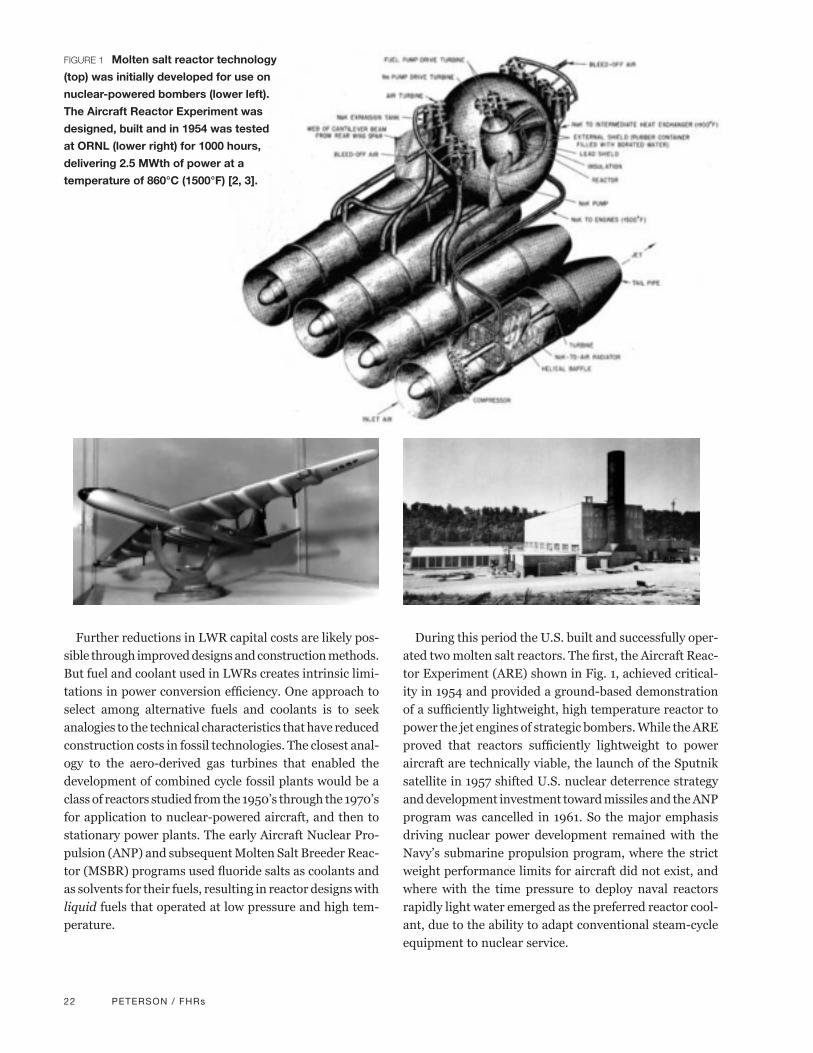
During this period the U.S. built and successfully oper-ated two molten salt reactors. The first, the Aircraft Reac-tor Experiment (ARE) shown in Fig. 1, achieved critical-ity in 1954 and provided a ground-based demonstration of a sufficiently lightweight, high temperature reactor to power the jet engines of strategic bombers. While the ARE proved that reactors sufficiently lightweight to power aircraft are technically viable, the launch of the Sputnik satellite in 1957 shifted U.S. nuclear deterrence strategy and development investment toward missiles and the ANP program was cancelled in 1961. So the major emphasis driving nuclear power development remained with the Navy’s submarine propulsion program, where the strict weight performance limits for aircraft did not exist, and where with the time pressure to deploy naval reactors rapidly light water emerged as the preferred reactor cool-ant, due to the ability to adapt conventional steam-cycle equipment to nuclear service.
FIGURE 1 Molten salt reactor technology
(top) was initially developed for use on
nuclear-powered bombers (lower left).
The Aircraft Reactor Experiment was
designed, built and in 1954 was tested
at ORNL (lower right) for 1000 hours,
delivering 2.5 MWth of power at a
temperature of 860°C (1500°F) [2, 3].

PETERSON / FHRs 23
As described in the Appendix, after the cancellation of the ANP program work to develop a Molten Salt Breeder Reactor (MSBR) for commercial applications continued at Oak Ridge National Laboratory (ORNL), in parallel with a substantially larger program to develop uranium-fueled liquid metal fast breeder reactors (LMFBR) centered at Argonne National Laboratory. Extensive research, documented in many thousands of pages of technical reports now available on-line [4], addressed problems in neutronics, heat transfer, chemistry, materials, and com-ponent design, leading to the construction and operation of the 8-MWth Molten Salt Reactor Experiment, which ran for 26,000 hours between 1965 and 1969. As compe-tition for resources increased, ultimately the molten salt reactor was cancelled in 1972, so that resources could be concentrated into the development of the LMFBR.
Starting from ideas proposed three decades later in 2002 [5], today a consortium of universities (UCB, MIT, and UW Madison), partnered with ORNL, are leading a new DOE-funded Integrated Research Project (IRP) to study a new high temperature reactor technology. The Advisory Panel that guides this IRP is chaired by a re-cently retired Chief Technology Officer of Westinghouse and has membership including recently retired Chief Nuclear Officer from Entergy, a recently retired Nuclear Science and Technology Division Director from ORNL, and representatives from two major nuclear technology consulting firms.
These new reactors – which are currently only concep-tual – would combine fuels derived from high temperature gas cooled reactors (HTGRs) with fluoride salts studied in the ANP and MSBR programs as their coolant. This combination of fuel and coolant, shown in Fig. 1, provides unique attributes. Called fluoride salt cooled high-tem-perature reactors (FHRs), the use of ceramic fuel and core structures in these reactors gives them the capability to deliver heat at temperatures above 600°C (1050°F), but without the high pressures of LWRs and HTGRs. Thus FHRs can achieve high power conversion efficiency while having similar compact size and low mass as did their original nuclear aircraft ancestor.
The entry barriers for any new commercial reactor technology are large. The baseline FHR design (solid, high-temperature ceramic fuel with a fluoride salt coolant, rather than a liquid fuel) has been selected to enable predictable and high reliability, as well as licenseability within a commercially attractive time frame.
2.0 Key Economic Metrics for FHRsExperts who estimate the capital cost of new engineered facilities like nuclear reactors focus their efforts on quan-
tifying the volumes and masses of materials needed for construction, counting numbers of components, estimat-ing labor requirements, determining schedules, and identifying sources of risk and uncertainty in these mate-rials, labor, and schedule estimates. Using cost data from earlier projects, and adjusting for interest during construc-tion, cost estimators can then generate total top-down cost estimates that can be used to assemble bids to perform new projects. Large FOAK projects tend to attract a small number of suppliers, who must build large contingencies into their FOAK prices due to the large downside risk of cost overruns. This is why nearly all modern Nuclear Steam Supply System (NSSS) reactor vendors have trended towards becoming as vertically-integrated as pos-sible, oftentimes in a transnational sense.
The risk associated with FOAK construction of large reactors reinforces the arguments for developing small modular reactors (SMRs), where the financial risks as-sociated with building a FOAK unit are reduced. With SMRs one can expect larger numbers of companies to enter into the competition to construct FOAK power plants and accept risk in order to gain experience and the abil-ity to bid accurately for subsequent projects. Because the SMR market is likely to attract more suppliers, customers can have higher confidence that the prices they pay are close to the actual costs of construction. Moreover, cus-tomers can benefit from easier financing for SMR projects and from the flexibility that SMRs provide in adjusting total generation capacity to optimal levels.
2.1 Metrics for Comparing Capital Costs of Different Reactors
Some key nuclear plant design metrics that affect capital cost include:l Reactor building height
l Reactor building volume per MWe
l Reactor building concrete volume per MWe
l Steel mass per MWe
l Core inlet/outlet temperature
l Primary coolant cost per MWe
l Core power density
l Primary system volume per MWe
l Primary system metal mass per MWe
Comparisons of values of these metrics can provide a rough, preliminary means to assess the potential differ-ences in construction costs of different types of reactors. Likewise, these metrics, along with other metrics relating to technical risk and financing, can be used to guide design decisions during conceptual design.
24 PETERSON / FHRs
The earliest FHR economics study, performed in 2004 [6], used the reactor primary system volume and building volume as the primary construction cost metrics. In this study an FHR was designed that used the same reactor building and reactor vessel size as the 1000-MWth, 380-MWe S-PRISM liquid metal reactor (LMR, also known as the Integral Fast Reactor, or IFR, developed after the cancellation of the U.S. LMFBR program). While the primary system and reactor building volume of this early FHR design was the same as the IFR, when designed with a core power density of 10 MWth/m3 (approximately twice the typical power density of a HTGR), could produce 2400 MWth (1145 MWe), 2.4 times more power than the IFR.
With further scaling for power conversion system costs, this 2004 study concluded that the capital cost of the FHR would be approximately 55% that of the IFR. This study also developed a capital cost comparison with the 600-MWth, 286-MWe GT-MHR, concluding that the capital cost would be 61% of this HTGR’s cost. Subsequent re-search has suggested that the optimal FHR power den-sity is likely to be yet higher, between 15 to 30 MWth/m3, so an FHR of this physical size could have a power output of 3600 to 7200 MWth (1700 to 3400 MWe), and thus yet lower capital cost.
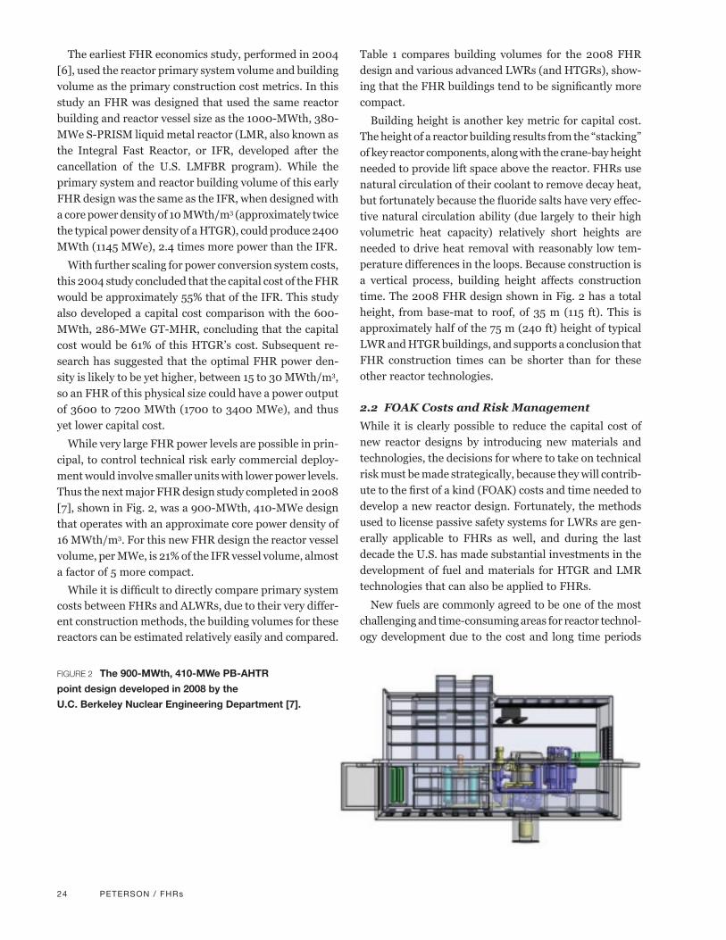
While very large FHR power levels are possible in prin-cipal, to control technical risk early commercial deploy-ment would involve smaller units with lower power levels. Thus the next major FHR design study completed in 2008 [7], shown in Fig. 2, was a 900-MWth, 410-MWe design that operates with an approximate core power density of 16 MWth/m3. For this new FHR design the reactor vessel volume, per MWe, is 21% of the IFR vessel volume, almost a factor of 5 more compact.
While it is difficult to directly compare primary system costs between FHRs and ALWRs, due to their very differ-ent construction methods, the building volumes for these reactors can be estimated relatively easily and compared.
Table 1 compares building volumes for the 2008 FHR design and various advanced LWRs (and HTGRs), show-ing that the FHR buildings tend to be significantly more compact.
Building height is another key metric for capital cost. The height of a reactor building results from the “stacking” of key reactor components, along with the crane-bay height needed to provide lift space above the reactor. FHRs use natural circulation of their coolant to remove decay heat, but fortunately because the fluoride salts have very effec-tive natural circulation ability (due largely to their high volumetric heat capacity) relatively short heights are needed to drive heat removal with reasonably low tem-perature differences in the loops. Because construction is a vertical process, building height affects construction time. The 2008 FHR design shown in Fig. 2 has a total height, from base-mat to roof, of 35 m (115 ft). This is approximately half of the 75 m (240 ft) height of typical LWR and HTGR buildings, and supports a conclusion that FHR construction times can be shorter than for these other reactor technologies.
2.2 FOAK Costs and Risk Management
While it is clearly possible to reduce the capital cost of new reactor designs by introducing new materials and technologies, the decisions for where to take on technical risk must be made strategically, because they will contrib-ute to the first of a kind (FOAK) costs and time needed to develop a new reactor design. Fortunately, the methods used to license passive safety systems for LWRs are gen-erally applicable to FHRs as well, and during the last decade the U.S. has made substantial investments in the development of fuel and materials for HTGR and LMR technologies that can also be applied to FHRs.
New fuels are commonly agreed to be one of the most challenging and time-consuming areas for reactor technol-ogy development due to the cost and long time periods
FIGURE 2 The 900-MWth, 410-MWe PB-AHTR
point design developed in 2008 by the
U.C. Berkeley Nuclear Engineering Department [7].

PETERSON / FHRs 25
Reactor TypeReactor Power (MWe)
Reactor & Auxiliaries
Volume(m3/MWe)
Turbine Building Volume
(m3/MWe)
Ancillary Structures
Volume (m3/MWe)
Total Building Volume
(m3/MWe)
1970’s PWR 1000 129 161 46 336
ABWR 1380 211 252 23 486
ESBWR 1550† 132† 166 45 343
EPR 1600 228 107 87 422
GT-MHR 286 388 0 24 412
PBMR 170 1015 0 270 1285
Modular PB-AHTR 410 98 104 40 242
† The ESBWR power and reactor building volume are updated values based on the Design Certification application arrangement drawings.
TABLE 1 Comparison of building volumes for various ALWRs and HTGRs, with an FHR [7].
needed to develop, irradiate and examine new fuels. For-tuitously for the FHR, the U.S. Next Generation Nuclear Plant (NGNP) project has established the full set of capa-bilities to fabricate, irradiate, and examine the coated particle fuels needed for FHRs [8]. This NGNP fuels program has demonstrated excellent fuel performance, with no fuel particle failures occurring. Because FHRs operate at much higher power density than HTGRs, their fuels reach full depletion more rapidly, allowing FHR fuels to be developed and tested on an accelerated schedule.
High temperature materials are a second key area where development and qualification is challenging. Here again the U.S. has made significant investments in the last decade to improve the understanding of materials performance at high temperatures, both for applications to HTGRs as well as LMRs [9]. A major issue for these high temperature reactor designs, and for the FHR, is that they use metallic structural materials at sufficiently high temperatures for long-term creep deformation to be important. It is chal-lenging to design vessels, pipes and heat exchangers to operate under conditions where such time-dependent behavior occurs. The DOE has sponsored significant work to update the ASME Boiler and Pressure Vessel code to integrate high temperature design rules into a new section called Division 5 [10]. Large databases of materials prop-erties are needed to predict time-dependent creep phe-nomena. For this reason, the FHR design has focused on using code-qualified materials such as 316 stainless steel, Alloy 800H, and Alloy N that already have extensive
property databases. Division 5 also includes design rules for graphite that are used in FHRs for key core structures including radial reflectors and upper core support struc-tures. While there are multiple vendors today who have the ability to design and construct components from these materials for nuclear applications today, further work to confirm the corrosion resistance of these materials under specific FHR conditions remains to be done and is the major work of UW Madison in the IRP effort.
3.0 FHR Safety, Design and LicensingFHRs have negative fuel and coolant temperature re-
activity feedback that causes the fission process to shut down if the reactor overheats, as well as additional diverse and redundant reactivity control and shutdown systems. As with other reactors, a key safety requirement for FHRs following shutdown is the removal of decay heat gener-ated by fission projects that continue to undergo radioac-tive decay after the fission process is stopped.
In FHRs decay heat is removed by buoyancy-driven natural circulation of the salt coolant. Under normal shutdown conditions decay heat is removed by a reliable normal shutdown cooling system shown in Fig. 3 that can function in both active (with AC power) and passive (no AC power) heat removal modes. Under emergency condi-tions where the normal shutdown cooling system is not available, a fully passive, safety-related Direct Reactor Auxiliary Cooling System (DRACS) is available that can
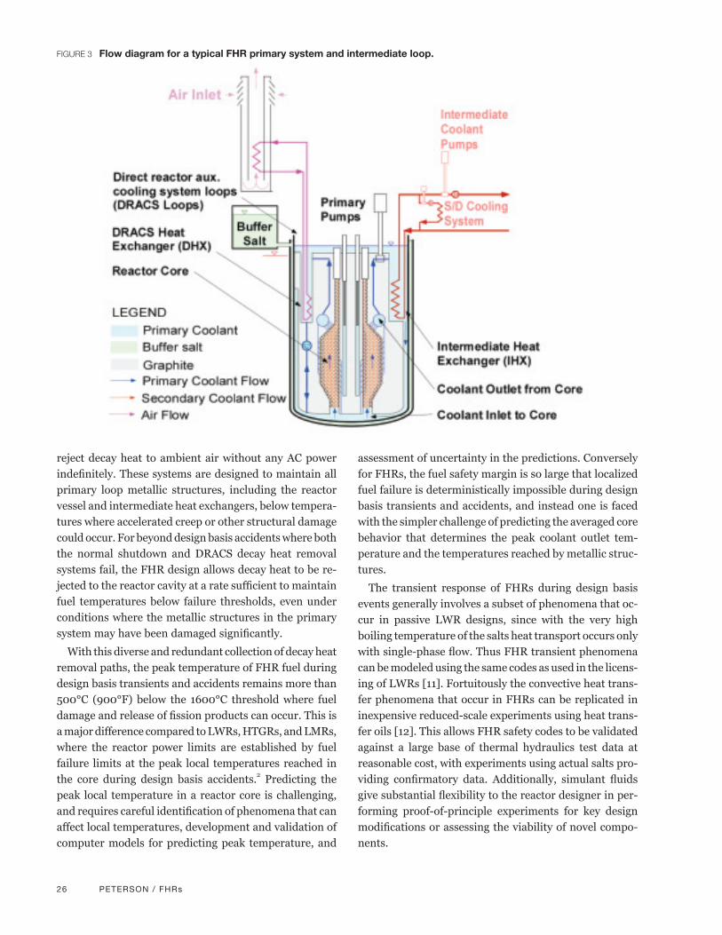
26 PETERSON / FHRs
reject decay heat to ambient air without any AC power indefinitely. These systems are designed to maintain all primary loop metallic structures, including the reactor vessel and intermediate heat exchangers, below tempera-tures where accelerated creep or other structural damage could occur. For beyond design basis accidents where both the normal shutdown and DRACS decay heat removal systems fail, the FHR design allows decay heat to be re-jected to the reactor cavity at a rate sufficient to maintain fuel temperatures below failure thresholds, even under conditions where the metallic structures in the primary system may have been damaged significantly.
With this diverse and redundant collection of decay heat removal paths, the peak temperature of FHR fuel during design basis transients and accidents remains more than 500°C (900°F) below the 1600°C threshold where fuel damage and release of fission products can occur. This is a major difference compared to LWRs, HTGRs, and LMRs, where the reactor power limits are established by fuel failure limits at the peak local temperatures reached in the core during design basis accidents.2 Predicting the peak local temperature in a reactor core is challenging, and requires careful identification of phenomena that can affect local temperatures, development and validation of computer models for predicting peak temperature, and
assessment of uncertainty in the predictions. Conversely for FHRs, the fuel safety margin is so large that localized fuel failure is deterministically impossible during design basis transients and accidents, and instead one is faced with the simpler challenge of predicting the averaged core behavior that determines the peak coolant outlet tem-perature and the temperatures reached by metallic struc-tures.
The transient response of FHRs during design basis events generally involves a subset of phenomena that oc-cur in passive LWR designs, since with the very high boiling temperature of the salts heat transport occurs only with single-phase flow. Thus FHR transient phenomena can be modeled using the same codes as used in the licens-ing of LWRs [11]. Fortuitously the convective heat trans-fer phenomena that occur in FHRs can be replicated in inexpensive reduced-scale experiments using heat trans-fer oils [12]. This allows FHR safety codes to be validated against a large base of thermal hydraulics test data at reasonable cost, with experiments using actual salts pro-viding confirmatory data. Additionally, simulant fluids give substantial flexibility to the reactor designer in per-forming proof-of-principle experiments for key design modifications or assessing the viability of novel compo-nents.
FIGURE 3 Flow diagram for a typical FHR primary system and intermediate loop.

PETERSON / FHRs 27
FHRs also have some attributes that could increase their costs and thus must be addressed carefully. These include the need to understand and control overcooling transients to prevent and mitigate consequences from salt freezing, the need to adapt the conventional beryllium industrial safety programs used by other industries to be integrated with the FHR’s radiation safety program, the need to develop and demonstrate methods to enrich lithium using non-mercury-based technologies,3 and the need to iden-tify and select a preferred power conversion technology from the options of open-air-Brayton cycles, supercritical steam cycles, and closed gas Brayton cycles.
Because licensing by the U.S. Nuclear Regulatory Com-mission is a key gateway activity for the commercial de-ployment of any new reactor technology in the United States, the MIT/UCB/UW IRP conducted a workshop with 20 licensing and reactor safety experts to review how li-censing methods developed in the U.S. for LWR, HTGR and LMR technologies can be adapted to use for FHRs [13]. This workshop identified no major issues for adapt-ing existing licensing methods to FHRs.
A second key gateway activity for commercial deploy-ment of FHRs is the construction of a 10 to 20 MWth Fluoride salt-cooled High-temperature Test Reactor (FHTR). While a large number of test reactors have been built and operated worldwide to provide the basis for understanding LWR, HTGR, LMR and MSBR technolo-gies, information from these earlier and current test reac-tors does not provide the information on the integrated performance of FHR systems, particularly for start up, power operation, and shutdown transients, needed to assess performance and safety characteristics of FHRs sufficiently to support licensing of a commercial prototype. University-based materials corrosion testing, irradiation, and thermal hydraulics experiments will be needed to support the design and licensing of the FHTR. Addition-ally, FHTR fuel development and testing using existing NGNP capabilities will be needed, as well as design, con-struction and operation of an FHR Component Test Facil-ity for non-nuclear testing of FHTR components under prototypical chemical and thermal conditions.
A final key gateway activity for commercial deployment of FHRs is the demonstration of reliable operation and the capability to achieve high levels of availability. Here the major elements involve the systematic identification of potential materials and component degradation mech-anisms; research to understand these mechanisms; par-ticularly corrosion of structural materials in the presence of prototypical salt chemical conditions; the development of reliable component designs and methods to perform
online monitoring, in-service inspection, maintenance and replacement; the use of event trees and probabilistic risk assessment to quantify overall system reliability; and the validation of these models through operating experi-ence in the FHR Component Test Facility and the FHTR.
4.0 ConclusionsThe FHR concept derives from a combination of a coolant, fuel, and structural materials originally selected in the 1950’s to develop a nuclear reactor with sufficiently low mass and high operating temperature to power the jet engines of a nuclear powered aircraft. The FHR concept recombines these materials into a new configuration that uses solid, high temperature fuel and maintains very high thermal margin to fuel damage while operating at comparable power density to the original aircraft reactor design. By producing substantially more power than al-ternative reactor technologies of similar physical size and by delivering heat at high average temperature, FHRs have the potential to have lower capital costs than alternative reactor technologies.
FHR technology could also support the development of future reactor technologies that could run more eco-nomically on recycled fuel. FHRs may be able to use “deep burn” fuels already studied for HTGRs, where the FHR coated particle fuel would fabricated from plutonium and other actinides. With deep burn fuel FHRs can effec-tively burn up to 70% of these transuranics. Likewise, the technology of FHRs closely overlaps that of metal-fueled fast-spectrum reactors including the IFR, which use fuel that can be fabricated much more easily from transuranics than can conventional oxide pellet fuels.
Finally, FHR technology closely overlaps that of the MSBR. Fluid fuels are easy to produce from recycled spent fuel, because the production of the fuel involves simple fluorination and separations processes, and no fabrication of recycled fuel is required. The Denatured Molten Salt Reactor [14] provides an example of a technology that could be used to recycle spent fuel from LWRs and FHRs, and that could also be used to transition to thorium-based fuel cycles that would operate sustainably with very low production of transuranics.
FHRs have the potential to serve as a bridge technol-ogy to more advanced reactor technologies. Given the current and anticipated low production costs for nuclear energy, today the key development issue for advanced reactors is to achieve sufficiently low capital cost to com-pete with LWRs and thus to increase the competitiveness of fission energy compared to its fossil alternatives.

28 PETERSON / FHRs
5.0 References1. Nuclear Energy Institute, “U.S. Electricity Production
Costs in 2010,” http://www.nei.org/filefolder/US_Electricity_Production_Costs.ppt.
2. J. Uhlir, “Chemistry and technology of Molten Salt Reactors – history and perspectives,” Journal of Nuclear Materials, Vol. 360, 6–11(2007).
3. H. G. MacPherson, “The Molten Salt Adventure,” Nuclear Science and Engineering, Vol. 90, 374-380 (1985).
4. http://energyfromthorium.com/msrp/
5. C.W. Forsberg, P. Pickard, and P.F. Peterson, “Mol-ten-Salt-Cooled Advanced High-Temperature Reactor for Production of Hydrogen and Electricity,” Nuclear Technology Vol. 144, pp. 289-302, 2003.
6. D.T. Ingersoll et al., “Status of Preconceptual Design of the Advanced High-Temperature Reactor (AHTR),” Oak Ridge National Laboratory, ORNL/TM-2004/104, May 2004.
7. D. Caron et al., “A Modular Pebble-Bed Advanced High Temperature Reactor,” NE-170 Senior Design Project, U.C. Berkeley Thermal Hydraulics Labora-tory, Report UCBTH-08-001, May 16, 2008.
8. “NGNP Fuel Qualification White Paper,” Idaho Na-tional Laboratory, INL/EXT-10-17686, Rev. 0, July 2010.
9. “NGNP High Temperature Materials White Paper,” Idaho National Laboratory, INL/EXT-09-17187, June 2010.
10. R. Sims and J. Nestell, Roadmap to Develop ASME Code Rules for the Construction of High Temperature Gas-Cooled Reactors (HTGRS), STP-NU-045 Rev. 1, Feb. 2012.
11. N. Zuber, “An Integrated Structure and Scaling Meth-odology for Severe Accident Technical Issue Resolu-tion, Appendix D,” U.S. Nuclear Regulatory Commis-sion, NUREG/CR-5809, 1991.
12. P. Bardet and P.F. Peterson, “Options for Scaled Ex-periments for High Temperature Liquid Salt and Helium Fluid Mechanics and Convective Heat Trans-fer,” Nuclear Technology, Vol. 163, pp. 344 – 357, 2008.
13. T. Cisneros, M. Laufer, and R. Scarlat, “Preliminary Fluoride Salt-Cooled High Temperature Reactor (FHR) Subsystems Definition, Functional Require-ment Definition and Licensing Basis Event (LBE) Identification White Paper,” Department of Nuclear Engineering, U.C. Berkeley, Report UCBTH-12-001, February, 2012.
14. J.R. Engel, et al., “Conceptual Design Characteristics of a Denatured Molten Salt Reactor With Once-Through Refueling,” Oak Ridge National Laboratory, ORNL/TM-7207, July 1980.
15. J.H. Shaffer, “Preparation and Handling of Salt Mix-tures for the Molten Salt Reactor Experiment,” Oak Ridge National Laboratory, ORNL-4616, January 1971.
16. “The Development Status of Molten-Salt Breeder Reactors,” ORNL-4812, August 1972.
Appendix: Historical Origins of the FHRThe historical origins of the FHR date back to the earliest phases of nuclear energy development, shortly after World War II when Ed Bettis and Ray Briant of Oak Ridge Na-tional Laboratory (ORNL) were placed in charge of a major, classified program to design a nuclear-powered aircraft, which would use a nuclear reactor to heat air hot enough to drive jet engines. Obviously, for an aircraft to fly with a nuclear reactor on board, this reactor system would have to have very low total mass and deliver heat at a sufficiently high temperature to drive gas turbine jet engines.
For the new Aircraft Nuclear Propulsion (ANP) program, Bettis and Briant settled upon an elegant solution to design an aircraft nuclear reactor. First, they selected a mixture of fluoride salts to serve as the coolant to transfer heat from the reactor. The fluoride salts were unique among the potential coolants due to their chemical inertness and the very large amount of heat these salts can absorb with a small change in temperature (greater than water and over four times larger than for sodium). Likewise, their very high boiling temperatures, above 1350°C (2400°F), allowed the reactors to operate at atmospheric pressure. With this high volumetric heat capacity, these salts could transfer a large amount of thermal power with a very low flow rate, allowing the use of small, thin-walled pipes and compact, light-weight pumps to move the fluid. In their design the fluoride salt coolant also served as a solvent for the uranium fuel.
To enable the reactor to achieve criticality and operate at high power with a very small amount of uranium fuel, Bettis and Briant selected the ceramic material beryllium oxide as a “moderator” for the reactor, knowing that the beryllium atoms are light and can effectively slow down neutrons during collisions, making it much easier for subsequent fission reactions to occur with only a small quantity of uranium fuel.
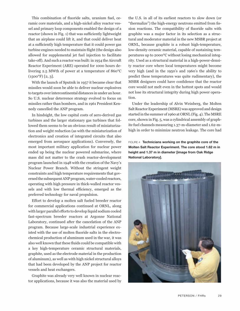
PETERSON / FHRs 29
This combination of fluoride salts, uranium fuel, ce-ramic core materials, and a high-nickel alloy reactor ves-sel and primary loop components enabled the design of a reactor (shown in Fig. 1) that was sufficiently lightweight that an airplane could lift it, and that could deliver heat at a sufficiently high temperature that it could power gas turbine engines needed to maintain flight (the design also allowed for supplemental jet fuel injection to facilitate take-off). And such a reactor was built: in 1954 the Aircraft Reactor Experiment (ARE) operated for 1000 hours de-livering 2.5 MWth of power at a temperature of 860°C (1500°F) [2, 3].
With the launch of Sputnik in 1957 it became clear that missiles would soon be able to deliver nuclear explosives to targets over intercontinental distances in under an hour. So U.S. nuclear deterrence strategy evolved to focus on missiles rather than bombers, and in 1961 President Ken-nedy cancelled the ANP program.
In hindsight, the low capital costs of aero-derived gas turbines and the larger stationary gas turbines that fol-lowed them seems to be an obvious result of miniaturiza-tion and weight reduction (as with the miniaturization of electronics and creation of integrated circuits that also emerged from aerospace applications). Conversely, the most important military application for nuclear power ended up being the nuclear powered submarine, where mass did not matter to the crash reactor-development program launched in 1948 with the creation of the Navy’s Nuclear Power Branch. Without the stringent weight constraints and high temperature requirements that gov-erned the subsequent ANP program, water-cooled reactors, operating with high pressure in thick-walled reactor ves-sels and with low thermal efficiency, emerged as the preferred technology for naval propulsion.
Effort to develop a molten salt fueled breeder reactor for commercial applications continued at ORNL, along with larger parallel efforts to develop liquid sodium cooled fast-spectrum breeder reactors at Argonne National Laboratory, continued after the cancelation of the ANP program. Because large-scale industrial experience ex-isted with the use of molten fluoride salts in the electro-chemical production of aluminum used in the war, it was also well known that these fluids could be compatible with a key high-temperature ceramic structural materials, graphite, used as the electrode material in the production of aluminum), as well as with high nickel structural alloys that had been developed by the ANP project for reactor vessels and heat exchangers.
Graphite was already very well known in nuclear reac-tor applications, because it was also the material used by
the U.S. in all of its earliest reactors to slow down (or “thermalize”) the high-energy neutrons emitted from fis-sion reactions. The compatibility of fluoride salts with graphite was a major factor in its selection as a struc-tural and moderator material in the new MSBR project at ORNL, because graphite is a robust high-temperature, low-density ceramic material, capable of sustaining tem-peratures up to 2000°C without losing mechanical integ-rity. Used as a structural material in a high-power-densi-ty reactor core where local temperatures might become very high (and in the 1950’s and 1960’s the ability to predict these temperatures was quite rudimentary), the MSBR designers could have confidence that the reactor core would not melt even in the hottest spots and would not lose its structural integrity during high power opera-tion.
Under the leadership of Alvin Weinberg, the Molten Salt Reactor Experiment (MSRE) was approved and design started in the summer of 1960 at ORNL (Fig. 4). The MSRE core, shown in Fig. 5, was a cylindrical assembly of graph-ite fuel channels measuring 1.37-m-diameter and 1.62-m-high in order to minimize neutron leakage. The core had
FIGURE 4 Technicians working on the graphite core of the
Molten Salt Reactor Experiment. The core stood 1.62 m in
height and 1.37 m in diameter [image from Oak Ridge
National Laboratory].
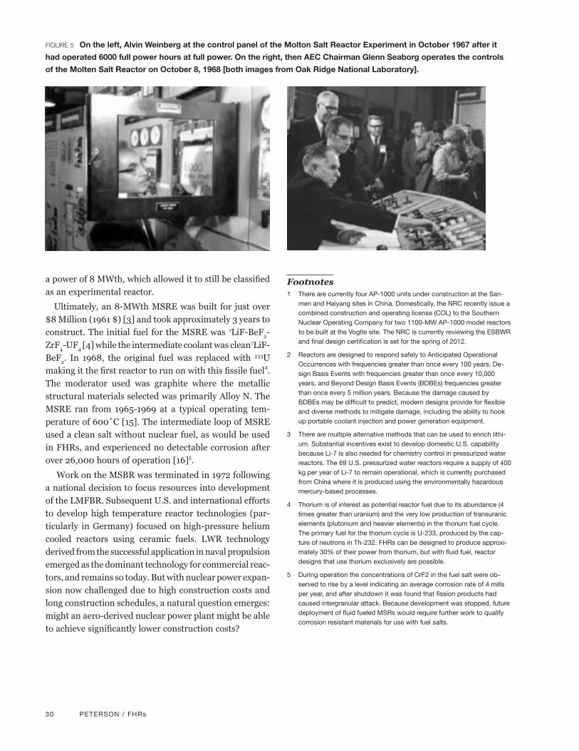
30 PETERSON / FHRs
a power of 8 MWth, which allowed it to still be classified as an experimental reactor.
Ultimately, an 8-MWth MSRE was built for just over $8 Million (1961 $) [3] and took approximately 3 years to construct. The initial fuel for the MSRE was 7LiF-BeF2-ZrF4-UF4 [4] while the intermediate coolant was clean7LiF-BeF2. In 1968, the original fuel was replaced with 233U making it the first reactor to run on with this fissile fuel4. The moderator used was graphite where the metallic structural materials selected was primarily Alloy N. The MSRE ran from 1965-1969 at a typical operating tem-perature of 600˚C [15]. The intermediate loop of MSRE used a clean salt without nuclear fuel, as would be used in FHRs, and experienced no detectable corrosion after over 26,000 hours of operation [16]5.
Work on the MSBR was terminated in 1972 following a national decision to focus resources into development of the LMFBR. Subsequent U.S. and international efforts to develop high temperature reactor technologies (par-ticularly in Germany) focused on high-pressure helium cooled reactors using ceramic fuels. LWR technology derived from the successful application in naval propulsion emerged as the dominant technology for commercial reac-tors, and remains so today. But with nuclear power expan-sion now challenged due to high construction costs and long construction schedules, a natural question emerges: might an aero-derived nuclear power plant might be able to achieve significantly lower construction costs?
Footnotes1 There are currently four AP-1000 units under construction at the San-
men and Haiyang sites in China. Domestically, the NRC recently issue a combined construction and operating license (COL) to the Southern Nuclear Operating Company for two 1100-MW AP-1000 model reactors to be built at the Vogtle site. The NRC is currently reviewing the ESBWR and final design certification is set for the spring of 2012.
2 Reactors are designed to respond safely to Anticipated Operational Occurrences with frequencies greater than once every 100 years, De-sign Basis Events with frequencies greater than once every 10,000 years, and Beyond Design Basis Events (BDBEs) frequencies greater than once every 5 million years. Because the damage caused by BDBEs may be difficult to predict, modern designs provide for flexible and diverse methods to mitigate damage, including the ability to hook up portable coolant injection and power generation equipment.
3 There are multiple alternative methods that can be used to enrich lithi-um. Substantial incentives exist to develop domestic U.S. capability because Li-7 is also needed for chemistry control in pressurized water reactors. The 69 U.S. pressurized water reactors require a supply of 400 kg per year of Li-7 to remain operational, which is currently purchased from China where it is produced using the environmentally hazardous mercury-based processes.
4 Thorium is of interest as potential reactor fuel due to its abundance (4 times greater than uranium) and the very low production of transuranic elements (plutonium and heavier elements) in the thorium fuel cycle. The primary fuel for the thorium cycle is U-233, produced by the cap-ture of neutrons in Th-232. FHRs can be designed to produce approxi-mately 30% of their power from thorium, but with fluid fuel, reactor designs that use thorium exclusively are possible.
5 During operation the concentrations of CrF2 in the fuel salt were ob-served to rise by a level indicating an average corrosion rate of 4 mills per year, and after shutdown it was found that fission products had caused intergranular attack. Because development was stopped, future deployment of fluid fueled MSRs would require further work to qualify corrosion resistant materials for use with fuel salts.
FIGURE 5 On the left, Alvin Weinberg at the control panel of the Molton Salt Reactor Experiment in October 1967 after it
had operated 6000 full power hours at full power. On the right, then AEC Chairman Glenn Seaborg operates the controls
of the Molten Salt Reactor on October 8, 1968 [both images from Oak Ridge National Laboratory].

AUTHORS’ BIOGRAPHIES 31
THEODORE U. MARSTON, PhD.Principal, Marston Consulting www.marstonconsulting.net
Upon retirement from the Electric Power Research Institute (EPRI) as its Chief Technology Officer, Dr. Marston established Marston Consulting in June of 2006. This firm is dedicated to the innovation, development, dem-onstration and deployment of new technology to address two key issues facing developed and developing countries in the 21st century: energy independence and management of global climate change. His clients include venture capitalists, commercial and energy companies, R&D organizations, and U.S. and interna-tional national laboratories.
Previously, as CTO of EPRI, he directed multi-hundred million dollar, international science and technology programs to improve the generation, transmission, distribution and utilization of electricity and reduce the associated environmental risks. Earlier, he led a large international program to develop utility requirements for
advanced nuclear reactors, design certification for advanced light water reactors, first-of-a-kind engineering and siting of nuclear reactors. In addition to his nuclear experience, he developed international, independent, fossil-fueled power generation projects. Ted has over 30 years of global experience in the assessment and management of risk in a broad range of industrial facilities, including nuclear and conventional power plants, refineries, chemical plants, railroads, and defense facilities.
He received his PhD in Mechanical Engineering from the University of Michigan in 1972 and is a Fellow of the American Society of Mechanical Engineers.
DR. ANDREW C. KADAKResearch Scientist and Former Professor of the Practice, Massachusetts Institute of Technology, Cambridge, MA
Dr. Kadak is a former Professor of the Practice in the Nuclear Science and Engineering Department at the Massachusetts Institute of Technology (MIT). His research interests include the development of advanced reactors, in particular the high-temperature pebble-bed gas reactor, space nuclear power systems, improved technology-neutral licensing standards for advanced reactors, and operation and management issues of exist-ing nuclear power plants. Before joining the faculty of MIT, Dr. Kadak was principal physicist for pressurized-water reactor physics at Combustion Engineering Corporation from 1972 to 1975, and held various positions at Yankee Atomic Electric Company from 1979 to 1987, including president and chief executive officer. He has served as a board and executive committee member of the Nuclear Energy Institute and the industry’s Advi-sory Committee on High-Level Waste. He also has served as a member of the National Association of Regula-
tory Utility Commissioners special panel on high-level nuclear waste and the Aspen Institute’s Dialogue on Nuclear Waste Disposal. In 1995, Dr. Kadak was a member of the Advisory Committee on External Regulation of DOE Nuclear Safety for the U.S. Department of Energy. He was president of the American Nuclear Society from 1999 to 2000. Dr. Kadak also serves as a Presidential Appointee on the US Nuclear Waste Technology Review Board overseeing the Department of Energy’s nuclear waste disposal program.
Dr. Kadak earned a bachelor’s degree in mechanical engineering from Union College in 1967, a master’s degree in nuclear engineering from the Massachusetts Institute of Technology in 1970, a Ph.D. in nuclear engineering from MIT in 1972, and an MBA from Northeastern University in 1983.
DR. PER PETERSONProfessor and Chair, Department of Nuclear Engineering, UC Berkeley
Per F. Peterson is Professor and Chair of the Department of Nuclear Engineering at the University of California, Berkeley. After joining UCB in 1990 as an Assistant Professor he received a NSF Presidential Young Investiga-tor award, and most recently received the Fusion Power Associates Excellence in Fusion Engineering Award and the American Nuclear Society Thermal Hydraulics Division Technical Achievement Award. His research interests focus on topics in heat and mass transfer, fluid dynamics, and phase change. He has worked on problems in energy and environmental systems, including advanced reactors, inertial fusion energy, high level nuclear waste processing, and nuclear materials management, with over 100 publications on these topics. His research group currently focuses on high-temperature heat transport for nuclear hydrogen and gas-cycle electricity production with high temperature reactors, and on the applications of liquid salt coolants in advanced nuclear energy systems. His broader interests in energy and environment focus on nuclear technologies and
nuclear materials management, and methods to enhance long-term proliferation resistance and physical security in the nuclear fuel cycle.
Dr. Peterson holds a B.S. in Mechanical Engineering, from the University of Nevada, Reno (1982), an M.S. in Mechanical Engineering from the University of California, Berkeley (1986), and a Ph.D. in Mechanical Engineering from the University of California, Berkeley (1988).
Authors’ Biographies

Notes

This page intentionally left blank.