Embed Size (px)
Citation preview
ESRI 380 New York St., Redlands, CA 92373-8100 USA • TEL 909-793-2853 • FAX 909-793-5953 • E-MAIL [email protected] • WEB www.esri.com
The Multipatch Geometry Type
An ESRI ® White Paper • December 2008

Copyright © 2008 ESRI All rights reserved. Printed in the United States of America. The information contained in this document is the exclusive property of ESRI. This work is protected under United States copyright law and other international copyright treaties and conventions. No part of this work may be reproduced or transmitted in any form or by any means, electronic or mechanical, including photocopying and recording, or by any information storage or retrieval system, except as expressly permitted in writing by ESRI. All requests should be sent to Attention: Contracts and Legal Services Manager, ESRI, 380 New York Street, Redlands, CA 92373-8100 USA. The information contained in this document is subject to change without notice. ESRI, the ESRI globe logo, ArcGIS, ArcObjects, EDN, ArcScene, ArcGlobe, ArcSDE, 3D Analyst, www.esri.com, and @esri.com are trademarks, registered trademarks, or service marks of ESRI in the United States, the European Community, or certain other jurisdictions. Other companies and products mentioned herein may be trademarks or registered trademarks of their respective trademark owners.

J-9749
ESRI White Paper i
The Multipatch Geometry Type
An ESRI White Paper Contents Page Introduction...........................................................................................1 Definition ..............................................................................................1 Geometry Construction.........................................................................2 Triangle Strip Examples .......................................................................3 Triangle Fan Examples .........................................................................13 Triangles Examples...............................................................................23 Ring Examples ......................................................................................39 Ring Group Examples...........................................................................50 IVector3D Examples.............................................................................68 ITransform3D Examples.......................................................................77 IConstruct MultiPatch Examples ..........................................................81 ConstructExtrude Between().................................................................113 Composite Examples ............................................................................117 Developer Sample: Multipatch Examples ............................................136 IGeneralMultiPatchCreator...................................................................138 Additional Notes ...................................................................................154 Additional Samples...............................................................................155

J-9749
ESRI White Paper
The Multipatch Geometry Type
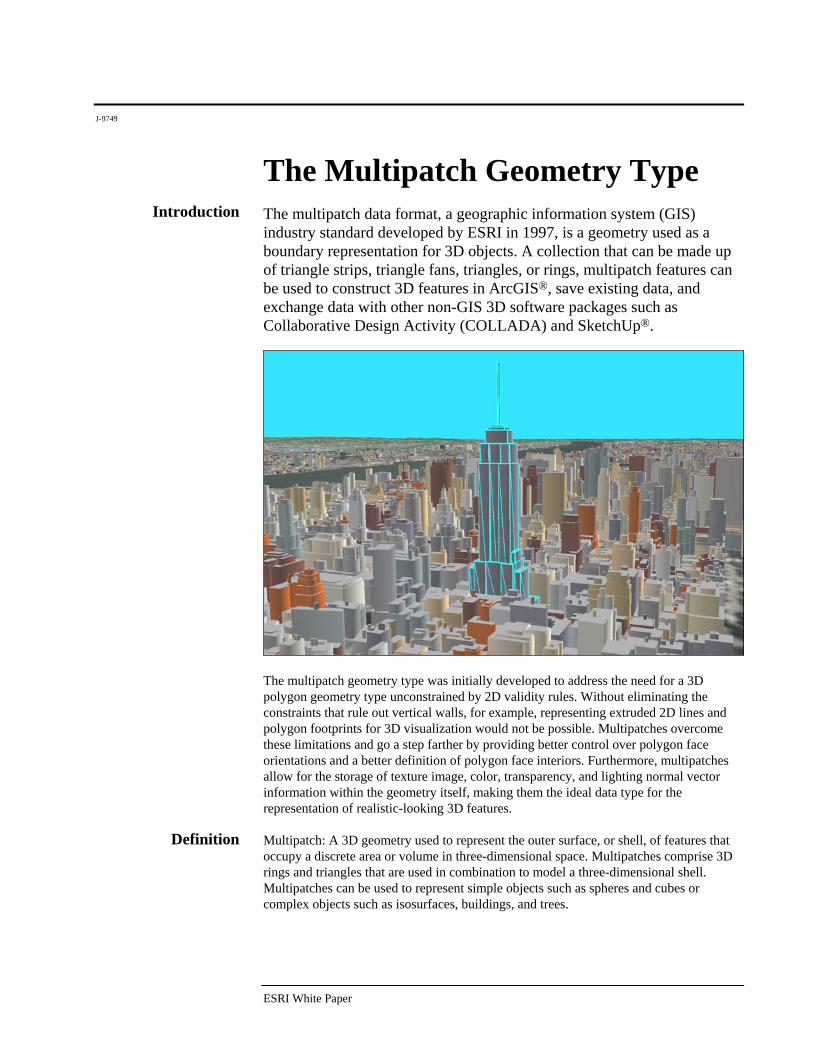
Introduction The multipatch data format, a geographic information system (GIS) industry standard developed by ESRI in 1997, is a geometry used as a boundary representation for 3D objects. A collection that can be made up of triangle strips, triangle fans, triangles, or rings, multipatch features can be used to construct 3D features in ArcGIS®, save existing data, and exchange data with other non-GIS 3D software packages such as Collaborative Design Activity (COLLADA) and SketchUp®.
The multipatch geometry type was initially developed to address the need for a 3D polygon geometry type unconstrained by 2D validity rules. Without eliminating the constraints that rule out vertical walls, for example, representing extruded 2D lines and polygon footprints for 3D visualization would not be possible. Multipatches overcome these limitations and go a step farther by providing better control over polygon face orientations and a better definition of polygon face interiors. Furthermore, multipatches allow for the storage of texture image, color, transparency, and lighting normal vector information within the geometry itself, making them the ideal data type for the representation of realistic-looking 3D features.
Definition Multipatch: A 3D geometry used to represent the outer surface, or shell, of features that occupy a discrete area or volume in three-dimensional space. Multipatches comprise 3D rings and triangles that are used in combination to model a three-dimensional shell. Multipatches can be used to represent simple objects such as spheres and cubes or complex objects such as isosurfaces, buildings, and trees.
The Multipatch Geometry Type
J-9749
December 2008 2
TriangleStrip TriangleFan Triangles Ring
* .. 1
* .. 1 1 .. *
1 .. *
MultiPatch
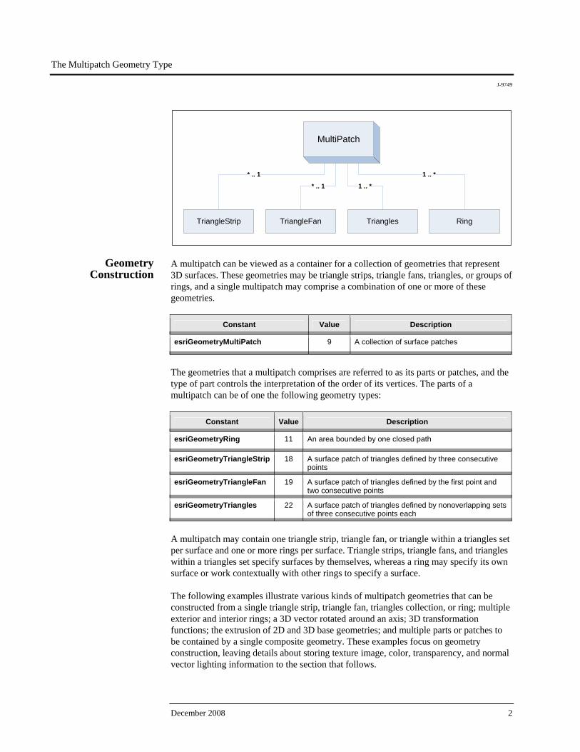
Geometry Construction
A multipatch can be viewed as a container for a collection of geometries that represent 3D surfaces. These geometries may be triangle strips, triangle fans, triangles, or groups of rings, and a single multipatch may comprise a combination of one or more of these geometries.
Constant Value Description
esriGeometryMultiPatch 9 A collection of surface patches
The geometries that a multipatch comprises are referred to as its parts or patches, and the type of part controls the interpretation of the order of its vertices. The parts of a multipatch can be of one the following geometry types:
Constant Value Description
esriGeometryRing 11 An area bounded by one closed path
esriGeometryTriangleStrip 18 A surface patch of triangles defined by three consecutive points
esriGeometryTriangleFan 19 A surface patch of triangles defined by the first point and two consecutive points
esriGeometryTriangles 22 A surface patch of triangles defined by nonoverlapping sets of three consecutive points each
A multipatch may contain one triangle strip, triangle fan, or triangle within a triangles set per surface and one or more rings per surface. Triangle strips, triangle fans, and triangles within a triangles set specify surfaces by themselves, whereas a ring may specify its own surface or work contextually with other rings to specify a surface. The following examples illustrate various kinds of multipatch geometries that can be constructed from a single triangle strip, triangle fan, triangles collection, or ring; multiple exterior and interior rings; a 3D vector rotated around an axis; 3D transformation functions; the extrusion of 2D and 3D base geometries; and multiple parts or patches to be contained by a single composite geometry. These examples focus on geometry construction, leaving details about storing texture image, color, transparency, and normal vector lighting information to the section that follows.
The Multipatch Geometry Type
J-9749
ESRI White Paper 3
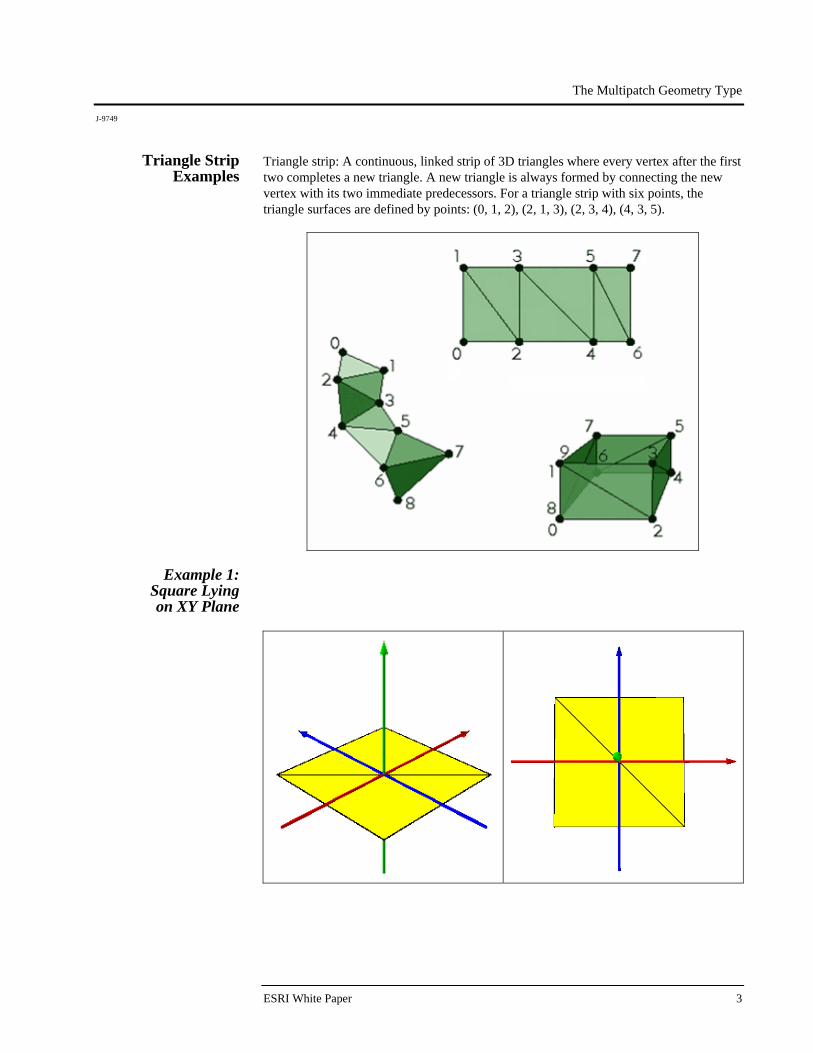
Triangle Strip Examples
Triangle strip: A continuous, linked strip of 3D triangles where every vertex after the first two completes a new triangle. A new triangle is always formed by connecting the new vertex with its two immediate predecessors. For a triangle strip with six points, the triangle surfaces are defined by points: (0, 1, 2), (2, 1, 3), (2, 3, 4), (4, 3, 5).
Example 1: Square Lying on XY Plane
The Multipatch Geometry Type
J-9749
December 2008 4
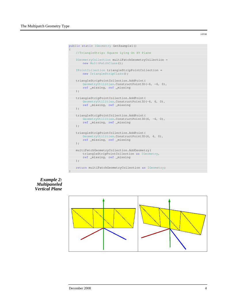
public static IGeometry GetExample1() { //TriangleStrip: Square Lying On XY Plane IGeometryCollection multiPatchGeometryCollection = new MultiPatchClass(); IPointCollection triangleStripPointCollection = new TriangleStripClass(); triangleStripPointCollection.AddPoint( GeometryUtilities.ConstructPoint3D(-6, -6, 0), ref _missing, ref _missing ); triangleStripPointCollection.AddPoint( GeometryUtilities.ConstructPoint3D(-6, 6, 0), ref _missing, ref _missing ); triangleStripPointCollection.AddPoint( GeometryUtilities.ConstructPoint3D(6, -6, 0), ref _missing, ref _missing ); triangleStripPointCollection.AddPoint( GeometryUtilities.ConstructPoint3D(6, 6, 0), ref _missing, ref _missing ); multiPatchGeometryCollection.AddGeometry( triangleStripPointCollection as IGeometry, ref _missing, ref _missing ); return multiPatchGeometryCollection as IGeometry; }
Example 2:
Multipaneled Vertical Plane
The Multipatch Geometry Type
J-9749
ESRI White Paper 5
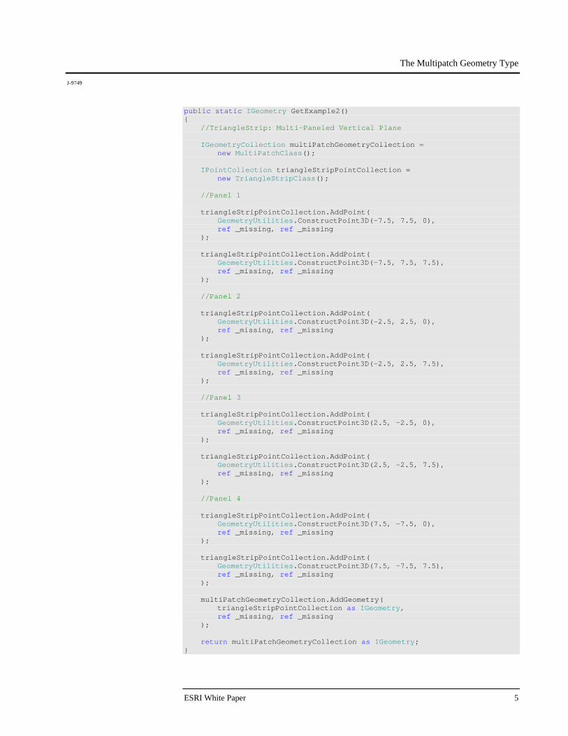
public static IGeometry GetExample2() { //TriangleStrip: Multi-Paneled Vertical Plane IGeometryCollection multiPatchGeometryCollection = new MultiPatchClass(); IPointCollection triangleStripPointCollection = new TriangleStripClass(); //Panel 1 triangleStripPointCollection.AddPoint( GeometryUtilities.ConstructPoint3D(-7.5, 7.5, 0), ref _missing, ref _missing ); triangleStripPointCollection.AddPoint( GeometryUtilities.ConstructPoint3D(-7.5, 7.5, 7.5), ref _missing, ref _missing ); //Panel 2 triangleStripPointCollection.AddPoint( GeometryUtilities.ConstructPoint3D(-2.5, 2.5, 0), ref _missing, ref _missing ); triangleStripPointCollection.AddPoint( GeometryUtilities.ConstructPoint3D(-2.5, 2.5, 7.5), ref _missing, ref _missing ); //Panel 3 triangleStripPointCollection.AddPoint( GeometryUtilities.ConstructPoint3D(2.5, -2.5, 0), ref _missing, ref _missing ); triangleStripPointCollection.AddPoint( GeometryUtilities.ConstructPoint3D(2.5, -2.5, 7.5), ref _missing, ref _missing ); //Panel 4 triangleStripPointCollection.AddPoint( GeometryUtilities.ConstructPoint3D(7.5, -7.5, 0), ref _missing, ref _missing ); triangleStripPointCollection.AddPoint( GeometryUtilities.ConstructPoint3D(7.5, -7.5, 7.5), ref _missing, ref _missing ); multiPatchGeometryCollection.AddGeometry( triangleStripPointCollection as IGeometry, ref _missing, ref _missing ); return multiPatchGeometryCollection as IGeometry; }

The Multipatch Geometry Type
J-9749
December 2008 6
Although the same surface could be represented by omitting the points that define Panel 3 and Panel 4, this example illustrates that a triangle strip can be composed of several triangles that lie in the same plane.
Example 3: Stairs
public static IGeometry GetExample3() { //TriangleStrip: Stairs IGeometryCollection multiPatchGeometryCollection = new MultiPatchClass(); IPointCollection triangleStripPointCollection = new TriangleStripClass(); //First Step triangleStripPointCollection.AddPoint( GeometryUtilities.ConstructPoint3D(0, 10, 10), ref _missing, ref _missing ); triangleStripPointCollection.AddPoint( GeometryUtilities.ConstructPoint3D(10, 10, 10), ref _missing, ref _missing ); triangleStripPointCollection.AddPoint( GeometryUtilities.ConstructPoint3D(0, 7.5, 10), ref _missing, ref _missing ); triangleStripPointCollection.AddPoint( GeometryUtilities.ConstructPoint3D(10, 7.5, 10), ref _missing, ref _missing );

The Multipatch Geometry Type
J-9749
ESRI White Paper 7
//Second Step triangleStripPointCollection.AddPoint( GeometryUtilities.ConstructPoint3D(0, 7.5, 7.5), ref _missing, ref _missing ); triangleStripPointCollection.AddPoint( GeometryUtilities.ConstructPoint3D(10, 7.5, 7.5), ref _missing, ref _missing ); triangleStripPointCollection.AddPoint( GeometryUtilities.ConstructPoint3D(0, 5, 7.5), ref _missing, ref _missing ); triangleStripPointCollection.AddPoint( GeometryUtilities.ConstructPoint3D(10, 5, 7.5), ref _missing, ref _missing ); //Third Step triangleStripPointCollection.AddPoint( GeometryUtilities.ConstructPoint3D(0, 5, 5), ref _missing, ref _missing ); triangleStripPointCollection.AddPoint( GeometryUtilities.ConstructPoint3D(10, 5, 5), ref _missing, ref _missing ); triangleStripPointCollection.AddPoint( GeometryUtilities.ConstructPoint3D(0, 2.5, 5), ref _missing, ref _missing ); triangleStripPointCollection.AddPoint( GeometryUtilities.ConstructPoint3D(10, 2.5, 5), ref _missing, ref _missing ); //Fourth Step triangleStripPointCollection.AddPoint( GeometryUtilities.ConstructPoint3D(0, 2.5, 2.5), ref _missing, ref _missing ); triangleStripPointCollection.AddPoint( GeometryUtilities.ConstructPoint3D(10, 2.5, 2.5), ref _missing, ref _missing ); triangleStripPointCollection.AddPoint( GeometryUtilities.ConstructPoint3D(0, 0, 2.5), ref _missing, ref _missing ); triangleStripPointCollection.AddPoint( GeometryUtilities.ConstructPoint3D(10, 0, 2.5), ref _missing, ref _missing );
The Multipatch Geometry Type
J-9749
December 2008 8
//End triangleStripPointCollection.AddPoint( GeometryUtilities.ConstructPoint3D(0, 0, 0), ref _missing, ref _missing ); triangleStripPointCollection.AddPoint( GeometryUtilities.ConstructPoint3D(10, 0, 0), ref _missing, ref _missing ); multiPatchGeometryCollection.AddGeometry( triangleStripPointCollection as IGeometry, ref _missing, ref _missing ); return multiPatchGeometryCollection as IGeometry; }
By setting every four vertices of a triangle strip to have the same z-value, we can generate a stair-shaped geometry.
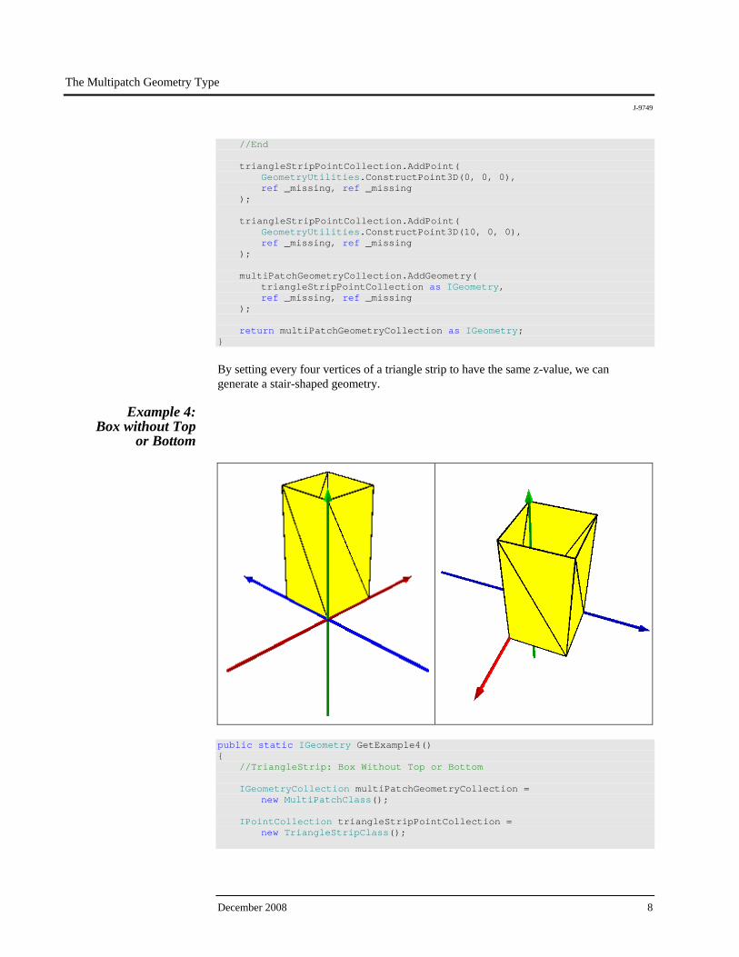
Example 4: Box without Top
or Bottom
public static IGeometry GetExample4() { //TriangleStrip: Box Without Top or Bottom IGeometryCollection multiPatchGeometryCollection = new MultiPatchClass(); IPointCollection triangleStripPointCollection = new TriangleStripClass();

The Multipatch Geometry Type
J-9749
ESRI White Paper 9
//Start triangleStripPointCollection.AddPoint( GeometryUtilities.ConstructPoint3D(0, 0, 0), ref _missing, ref _missing ); triangleStripPointCollection.AddPoint( GeometryUtilities.ConstructPoint3D(0, 0, 10), ref _missing, ref _missing ); //First Panel triangleStripPointCollection.AddPoint( GeometryUtilities.ConstructPoint3D(5, 0, 0), ref _missing, ref _missing ); triangleStripPointCollection.AddPoint( GeometryUtilities.ConstructPoint3D(5, 0, 10), ref _missing, ref _missing ); //Second Panel triangleStripPointCollection.AddPoint( GeometryUtilities.ConstructPoint3D(5, 5, 0), ref _missing, ref _missing ); triangleStripPointCollection.AddPoint( GeometryUtilities.ConstructPoint3D(5, 5, 10), ref _missing, ref _missing ); //Third Panel triangleStripPointCollection.AddPoint( GeometryUtilities.ConstructPoint3D(0, 5, 0), ref _missing, ref _missing ); triangleStripPointCollection.AddPoint( GeometryUtilities.ConstructPoint3D(0, 5, 10), ref _missing, ref _missing ); //End, To Close Box triangleStripPointCollection.AddPoint( GeometryUtilities.ConstructPoint3D(0, 0, 0), ref _missing, ref _missing ); triangleStripPointCollection.AddPoint( GeometryUtilities.ConstructPoint3D(0, 0, 10), ref _missing, ref _missing );
The Multipatch Geometry Type
J-9749
December 2008 10
multiPatchGeometryCollection.AddGeometry( triangleStripPointCollection as IGeometry, ref _missing, ref _missing ); return multiPatchGeometryCollection as IGeometry; }
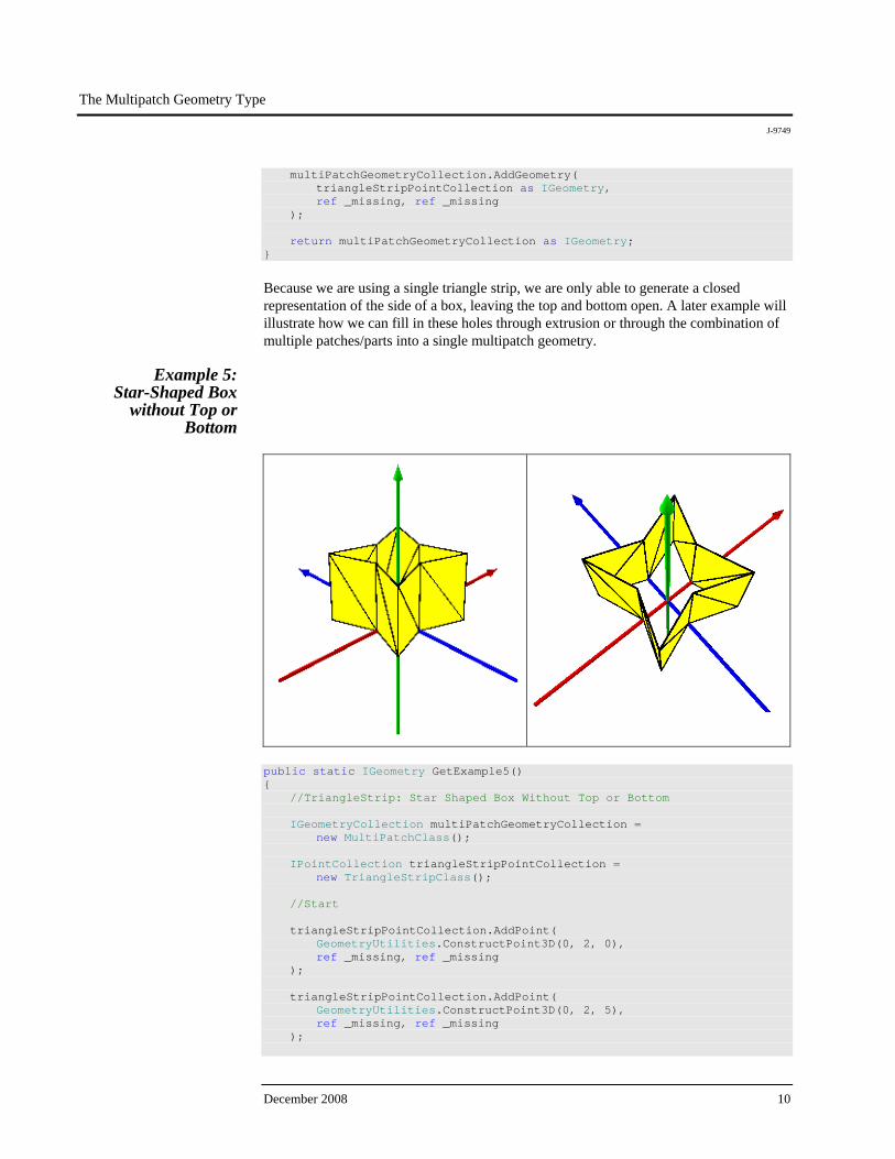
Because we are using a single triangle strip, we are only able to generate a closed representation of the side of a box, leaving the top and bottom open. A later example will illustrate how we can fill in these holes through extrusion or through the combination of multiple patches/parts into a single multipatch geometry.
Example 5: Star-Shaped Box
without Top or Bottom
public static IGeometry GetExample5() { //TriangleStrip: Star Shaped Box Without Top or Bottom IGeometryCollection multiPatchGeometryCollection = new MultiPatchClass(); IPointCollection triangleStripPointCollection = new TriangleStripClass(); //Start triangleStripPointCollection.AddPoint( GeometryUtilities.ConstructPoint3D(0, 2, 0), ref _missing, ref _missing ); triangleStripPointCollection.AddPoint( GeometryUtilities.ConstructPoint3D(0, 2, 5), ref _missing, ref _missing );
The Multipatch Geometry Type
J-9749
ESRI White Paper 11
//First Panel triangleStripPointCollection.AddPoint( GeometryUtilities.ConstructPoint3D( -1 * Math.Sqrt(10), Math.Sqrt(10), 0 ), ref _missing, ref _missing ); triangleStripPointCollection.AddPoint( GeometryUtilities.ConstructPoint3D( -1 * Math.Sqrt(10), Math.Sqrt(10), 5 ), ref _missing, ref _missing ); //Second Panel triangleStripPointCollection.AddPoint( GeometryUtilities.ConstructPoint3D(-2, 0, 0), ref _missing, ref _missing ); triangleStripPointCollection.AddPoint( GeometryUtilities.ConstructPoint3D(-2, 0, 5), ref _missing, ref _missing ); //Third Panel triangleStripPointCollection.AddPoint( GeometryUtilities.ConstructPoint3D( -1 * Math.Sqrt(10), -1 * Math.Sqrt(10), 0 ), ref _missing, ref _missing ); triangleStripPointCollection.AddPoint( GeometryUtilities.ConstructPoint3D( -1 * Math.Sqrt(10), -1 * Math.Sqrt(10), 5 ), ref _missing, ref _missing ); //Fourth Panel triangleStripPointCollection.AddPoint( GeometryUtilities.ConstructPoint3D(0, -2, 0), ref _missing, ref _missing ); triangleStripPointCollection.AddPoint( GeometryUtilities.ConstructPoint3D(0, -2, 5), ref _missing, ref _missing ); //Fifth Panel triangleStripPointCollection.AddPoint( GeometryUtilities.ConstructPoint3D( Math.Sqrt(10), -1 * Math.Sqrt(10), 0 ), ref _missing, ref _missing );

The Multipatch Geometry Type
J-9749
December 2008 12
triangleStripPointCollection.AddPoint( GeometryUtilities.ConstructPoint3D( Math.Sqrt(10), -1 * Math.Sqrt(10), 5 ), ref _missing, ref _missing ); //Sixth Panel triangleStripPointCollection.AddPoint( GeometryUtilities.ConstructPoint3D(2, 0, 0), ref _missing, ref _missing ); triangleStripPointCollection.AddPoint( GeometryUtilities.ConstructPoint3D(2, 0, 5), ref _missing, ref _missing ); //Seventh Panel triangleStripPointCollection.AddPoint( GeometryUtilities.ConstructPoint3D( Math.Sqrt(10), Math.Sqrt(10), 0 ), ref _missing, ref _missing ); triangleStripPointCollection.AddPoint( GeometryUtilities.ConstructPoint3D( Math.Sqrt(10), Math.Sqrt(10), 5 ), ref _missing, ref _missing ); //End, To Close Box triangleStripPointCollection.AddPoint( GeometryUtilities.ConstructPoint3D(0, 2, 0), ref _missing, ref _missing ); triangleStripPointCollection.AddPoint( GeometryUtilities.ConstructPoint3D(0, 2, 5), ref _missing, ref _missing ); multiPatchGeometryCollection.AddGeometry( triangleStripPointCollection as IGeometry, ref _missing, ref _missing ); return multiPatchGeometryCollection as IGeometry; }
The Multipatch Geometry Type
J-9749
ESRI White Paper 13
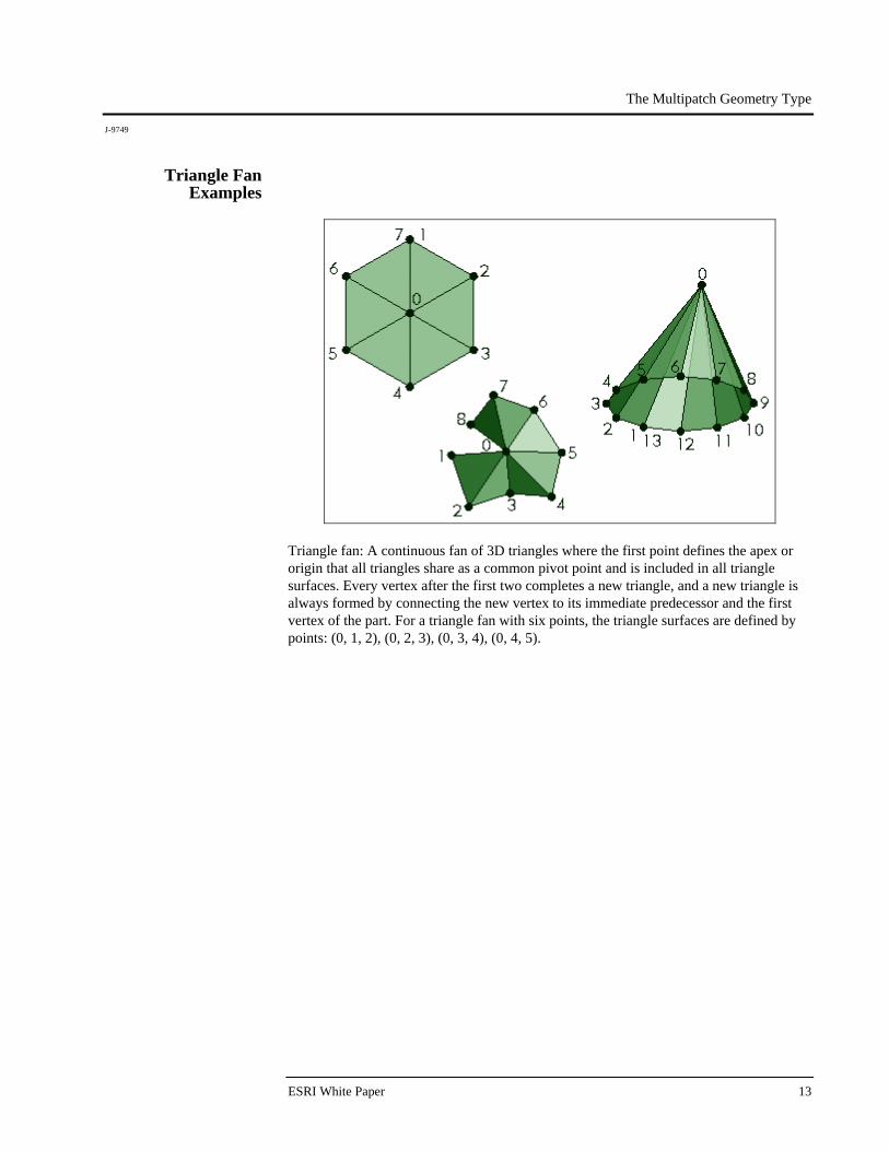
Triangle Fan Examples
Triangle fan: A continuous fan of 3D triangles where the first point defines the apex or origin that all triangles share as a common pivot point and is included in all triangle surfaces. Every vertex after the first two completes a new triangle, and a new triangle is always formed by connecting the new vertex to its immediate predecessor and the first vertex of the part. For a triangle fan with six points, the triangle surfaces are defined by points: (0, 1, 2), (0, 2, 3), (0, 3, 4), (0, 4, 5).
The Multipatch Geometry Type
J-9749
December 2008 14
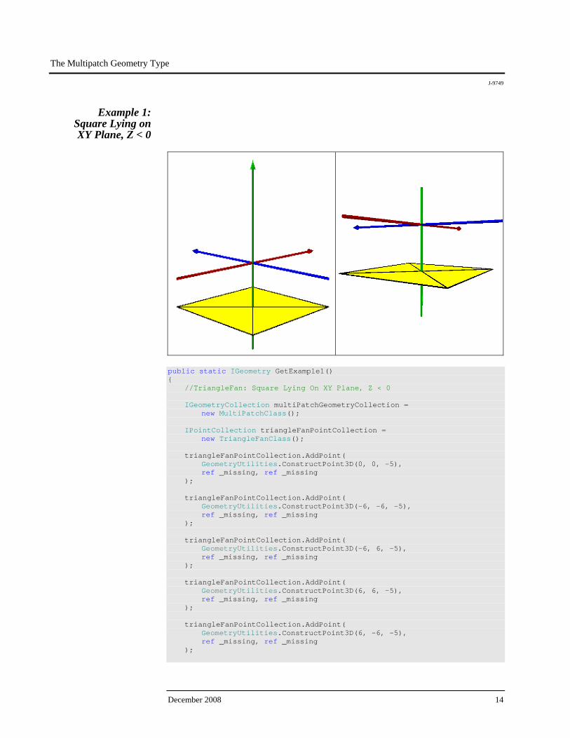
Example 1: Square Lying on XY Plane, Z < 0
public static IGeometry GetExample1() { //TriangleFan: Square Lying On XY Plane, Z < 0 IGeometryCollection multiPatchGeometryCollection = new MultiPatchClass(); IPointCollection triangleFanPointCollection = new TriangleFanClass(); triangleFanPointCollection.AddPoint( GeometryUtilities.ConstructPoint3D(0, 0, -5), ref _missing, ref _missing ); triangleFanPointCollection.AddPoint( GeometryUtilities.ConstructPoint3D(-6, -6, -5), ref _missing, ref _missing ); triangleFanPointCollection.AddPoint( GeometryUtilities.ConstructPoint3D(-6, 6, -5), ref _missing, ref _missing ); triangleFanPointCollection.AddPoint( GeometryUtilities.ConstructPoint3D(6, 6, -5), ref _missing, ref _missing ); triangleFanPointCollection.AddPoint( GeometryUtilities.ConstructPoint3D(6, -6, -5), ref _missing, ref _missing );
The Multipatch Geometry Type
J-9749
ESRI White Paper 15
triangleFanPointCollection.AddPoint( GeometryUtilities.ConstructPoint3D(-6, -6, -5), ref _missing, ref _missing ); multiPatchGeometryCollection.AddGeometry( triangleFanPointCollection as IGeometry, ref _missing, ref _missing ); return multiPatchGeometryCollection as IGeometry; }
Previous examples showed how a multipatch could be positioned at or above the XY plane at z = 0. This example illustrates how a multipatch can be positioned anywhere in 3D space. Because the centerpoint or origin of the triangle fan has the same z-value as its vertices, the triangle fan appears as a ring. As we will see in a later example, a ring would be better suited to represent this surface as it would not require a vertex to represent the centerpoint or origin and would result in a geometry with one less vertex than the equivalent triangle fan representation. Note that we need to re-add the second vertex of the triangle fan to close the fan. Otherwise, a triangle-shaped gap will appear between the last vertex, first vertex, and origin.
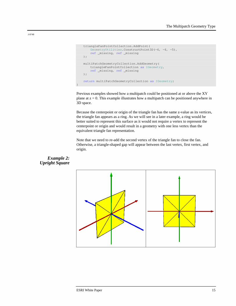
Example 2: Upright Square

The Multipatch Geometry Type
J-9749
December 2008 16
public static IGeometry GetExample2() { //TriangleFan: Upright Square IGeometryCollection multiPatchGeometryCollection = new MultiPatchClass(); IPointCollection triangleFanPointCollection = new TriangleFanClass(); triangleFanPointCollection.AddPoint( GeometryUtilities.ConstructPoint3D(0, 0, 0), ref _missing, ref _missing ); triangleFanPointCollection.AddPoint( GeometryUtilities.ConstructPoint3D(-5, 0, -5), ref _missing, ref _missing ); triangleFanPointCollection.AddPoint( GeometryUtilities.ConstructPoint3D(-5, 0, 5), ref _missing, ref _missing ); triangleFanPointCollection.AddPoint( GeometryUtilities.ConstructPoint3D(5, 0, 5), ref _missing, ref _missing ); triangleFanPointCollection.AddPoint( GeometryUtilities.ConstructPoint3D(5, 0, -5), ref _missing, ref _missing ); triangleFanPointCollection.AddPoint( GeometryUtilities.ConstructPoint3D(-5, 0, -5), ref _missing, ref _missing ); multiPatchGeometryCollection.AddGeometry( triangleFanPointCollection as IGeometry, ref _missing, ref _missing ); return multiPatchGeometryCollection as IGeometry; }
The Multipatch Geometry Type
J-9749
ESRI White Paper 17
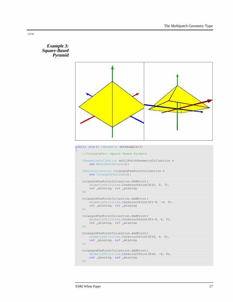
Example 3: Square-Based
Pyramid
public static IGeometry GetExample3() { //TriangleFan: Square Based Pyramid IGeometryCollection multiPatchGeometryCollection = new MultiPatchClass(); IPointCollection triangleFanPointCollection = new TriangleFanClass(); triangleFanPointCollection.AddPoint( GeometryUtilities.ConstructPoint3D(0, 0, 7), ref _missing, ref _missing ); triangleFanPointCollection.AddPoint( GeometryUtilities.ConstructPoint3D(-6, -6, 0), ref _missing, ref _missing ); triangleFanPointCollection.AddPoint( GeometryUtilities.ConstructPoint3D(-6, 6, 0), ref _missing, ref _missing ); triangleFanPointCollection.AddPoint( GeometryUtilities.ConstructPoint3D(6, 6, 0), ref _missing, ref _missing ); triangleFanPointCollection.AddPoint( GeometryUtilities.ConstructPoint3D(6, -6, 0), ref _missing, ref _missing );
The Multipatch Geometry Type
J-9749
December 2008 18
triangleFanPointCollection.AddPoint( GeometryUtilities.ConstructPoint3D(-6, -6, 0), ref _missing, ref _missing ); multiPatchGeometryCollection.AddGeometry( triangleFanPointCollection as IGeometry, ref _missing, ref _missing ); return multiPatchGeometryCollection as IGeometry; }
By setting the z-value of the centerpoint or origin of the triangle fan to a value that differs from the z-value of the triangle fan's vertices, the triangle fan no longer appears as a ring but rather appears as a pyramid or cone.
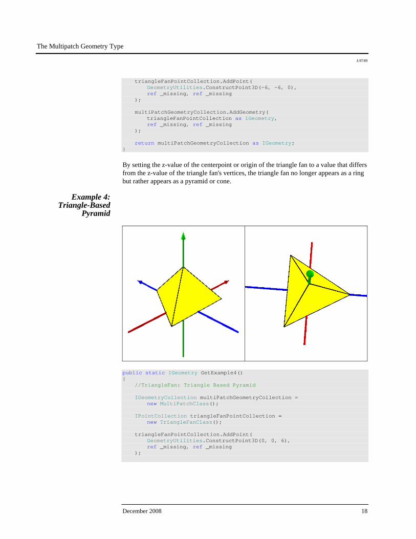
Example 4: Triangle-Based
Pyramid
public static IGeometry GetExample4() { //TriangleFan: Triangle Based Pyramid IGeometryCollection multiPatchGeometryCollection = new MultiPatchClass(); IPointCollection triangleFanPointCollection = new TriangleFanClass(); triangleFanPointCollection.AddPoint( GeometryUtilities.ConstructPoint3D(0, 0, 6), ref _missing, ref _missing );
The Multipatch Geometry Type
J-9749
ESRI White Paper 19
triangleFanPointCollection.AddPoint( GeometryUtilities.ConstructPoint3D( -3 * Math.Sqrt(3), -3, 0 ), ref _missing, ref _missing ); triangleFanPointCollection.AddPoint( GeometryUtilities.ConstructPoint3D(0, 6, 0), ref _missing, ref _missing ); triangleFanPointCollection.AddPoint( GeometryUtilities.ConstructPoint3D( 3 * Math.Sqrt(3), -3, 0 ), ref _missing, ref _missing ); triangleFanPointCollection.AddPoint( GeometryUtilities.ConstructPoint3D( -3 * Math.Sqrt(3), -3, 0 ), ref _missing, ref _missing ); multiPatchGeometryCollection.AddGeometry( triangleFanPointCollection as IGeometry, ref _missing, ref _missing ); return multiPatchGeometryCollection as IGeometry; }
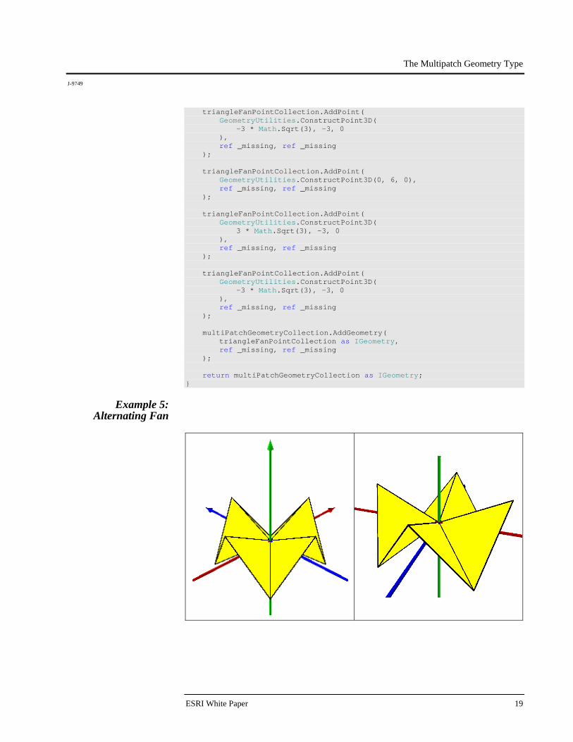
Example 5:
Alternating Fan

The Multipatch Geometry Type
J-9749
December 2008 20
public static IGeometry GetExample5() { //TriangleFan: Alternating Fan IGeometryCollection multiPatchGeometryCollection = new MultiPatchClass(); IPointCollection triangleFanPointCollection = new TriangleFanClass(); triangleFanPointCollection.AddPoint( GeometryUtilities.ConstructPoint3D(0, 0, 0), ref _missing, ref _missing ); triangleFanPointCollection.AddPoint( GeometryUtilities.ConstructPoint3D(0, -6, 3), ref _missing, ref _missing ); triangleFanPointCollection.AddPoint( GeometryUtilities.ConstructPoint3D( -3 * Math.Sqrt(2), -3 * Math.Sqrt(2), -3 ), ref _missing, ref _missing ); triangleFanPointCollection.AddPoint( GeometryUtilities.ConstructPoint3D(-6, 0, 3), ref _missing, ref _missing ); triangleFanPointCollection.AddPoint( GeometryUtilities.ConstructPoint3D( -3 * Math.Sqrt(2), 3 * Math.Sqrt(2), -3 ), ref _missing, ref _missing ); triangleFanPointCollection.AddPoint( GeometryUtilities.ConstructPoint3D(0, 6, 3), ref _missing, ref _missing ); triangleFanPointCollection.AddPoint( GeometryUtilities.ConstructPoint3D( 3 * Math.Sqrt(2), 3 * Math.Sqrt(2), -3 ), ref _missing, ref _missing ); triangleFanPointCollection.AddPoint( GeometryUtilities.ConstructPoint3D(6, 0, 3), ref _missing, ref _missing ); triangleFanPointCollection.AddPoint( GeometryUtilities.ConstructPoint3D( 3 * Math.Sqrt(2), -3 * Math.Sqrt(2), -3 ), ref _missing, ref _missing );
The Multipatch Geometry Type
J-9749
ESRI White Paper 21
triangleFanPointCollection.AddPoint( GeometryUtilities.ConstructPoint3D(0, -6, 3), ref _missing, ref _missing ); multiPatchGeometryCollection.AddGeometry( triangleFanPointCollection as IGeometry, ref _missing, ref _missing ); return multiPatchGeometryCollection as IGeometry; }
When adjacent vertices have differing z-values, a fanlike geometry is produced.
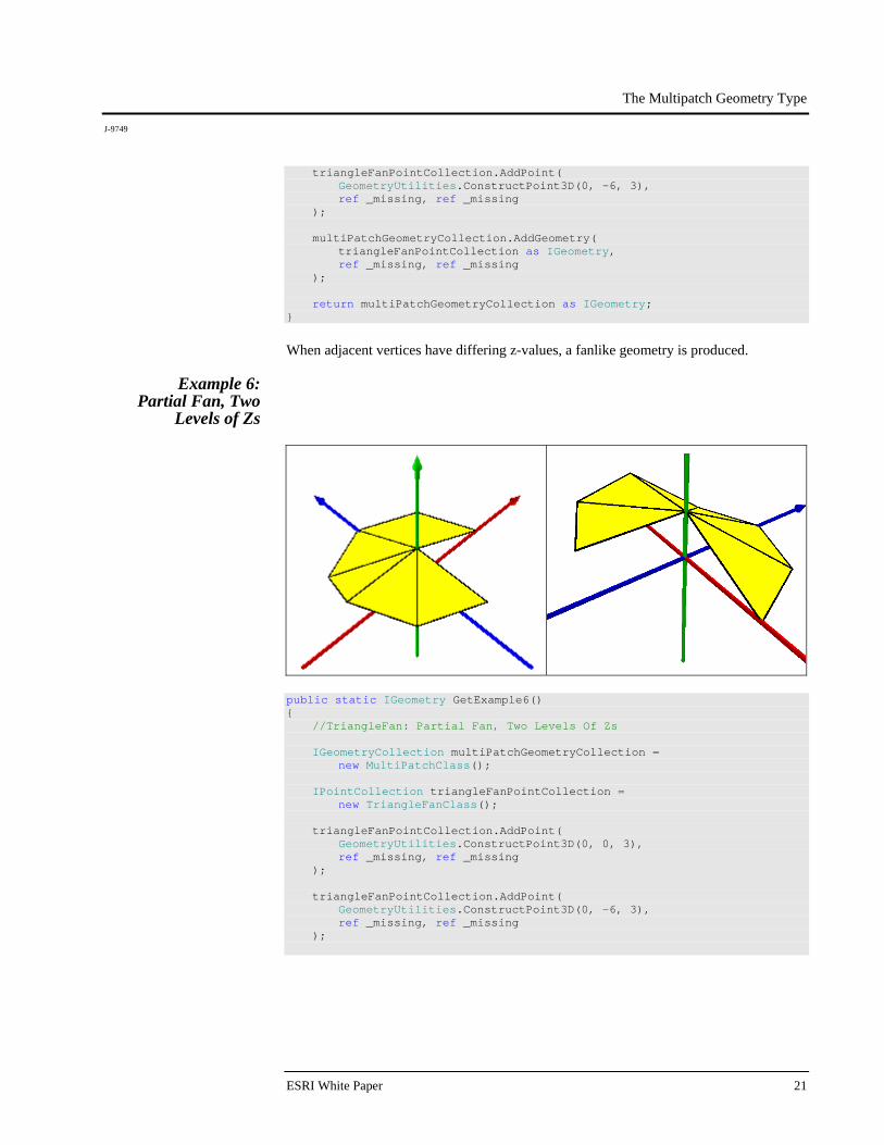
Example 6: Partial Fan, Two
Levels of Zs
public static IGeometry GetExample6() { //TriangleFan: Partial Fan, Two Levels Of Zs IGeometryCollection multiPatchGeometryCollection = new MultiPatchClass(); IPointCollection triangleFanPointCollection = new TriangleFanClass(); triangleFanPointCollection.AddPoint( GeometryUtilities.ConstructPoint3D(0, 0, 3), ref _missing, ref _missing ); triangleFanPointCollection.AddPoint( GeometryUtilities.ConstructPoint3D(0, -6, 3), ref _missing, ref _missing );

The Multipatch Geometry Type
J-9749
December 2008 22
triangleFanPointCollection.AddPoint( GeometryUtilities.ConstructPoint3D( -3 * Math.Sqrt(2), -3 * Math.Sqrt(2), 3 ), ref _missing, ref _missing ); triangleFanPointCollection.AddPoint( GeometryUtilities.ConstructPoint3D(-6, 0, 3), ref _missing, ref _missing ); triangleFanPointCollection.AddPoint( GeometryUtilities.ConstructPoint3D( -3 * Math.Sqrt(2), 3 * Math.Sqrt(2), 0 ), ref _missing, ref _missing ); triangleFanPointCollection.AddPoint( GeometryUtilities.ConstructPoint3D(0, 6, 0), ref _missing, ref _missing ); triangleFanPointCollection.AddPoint( GeometryUtilities.ConstructPoint3D( 3 * Math.Sqrt(2), 3 * Math.Sqrt(2), 0 ), ref _missing, ref _missing ); triangleFanPointCollection.AddPoint( GeometryUtilities.ConstructPoint3D(6, 0, 0), ref _missing, ref _missing ); multiPatchGeometryCollection.AddGeometry( triangleFanPointCollection as IGeometry, ref _missing, ref _missing ); return multiPatchGeometryCollection as IGeometry; }
A triangle fan does not need to be closed, and this example illustrates one such triangle fan representation.
The Multipatch Geometry Type
J-9749
ESRI White Paper 23
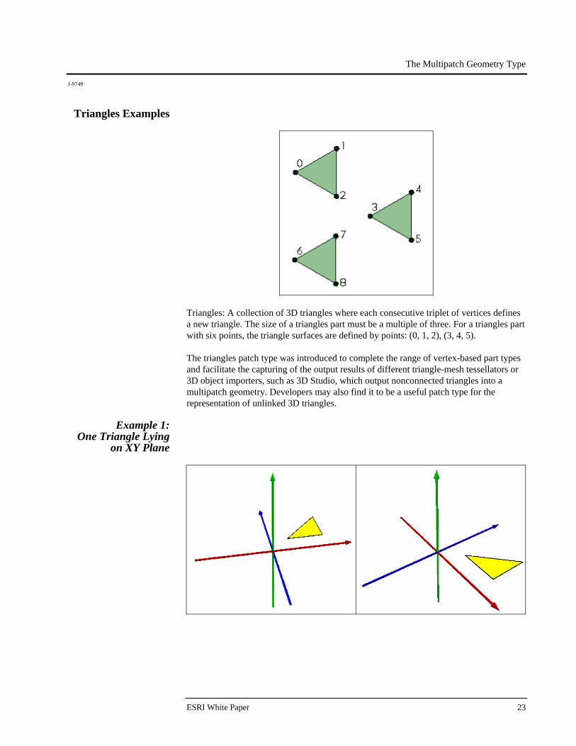
Triangles Examples
Triangles: A collection of 3D triangles where each consecutive triplet of vertices defines a new triangle. The size of a triangles part must be a multiple of three. For a triangles part with six points, the triangle surfaces are defined by points: (0, 1, 2), (3, 4, 5). The triangles patch type was introduced to complete the range of vertex-based part types and facilitate the capturing of the output results of different triangle-mesh tessellators or 3D object importers, such as 3D Studio, which output nonconnected triangles into a multipatch geometry. Developers may also find it to be a useful patch type for the representation of unlinked 3D triangles.
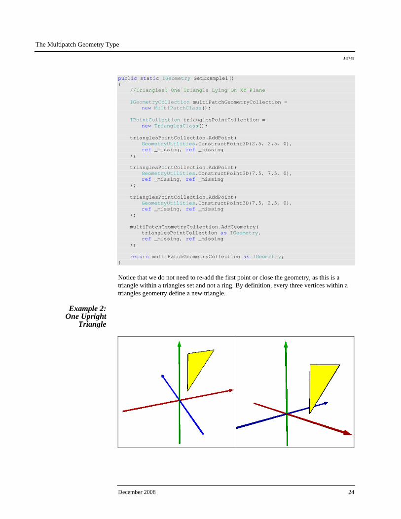
Example 1: One Triangle Lying
on XY Plane
The Multipatch Geometry Type
J-9749
December 2008 24
public static IGeometry GetExample1() { //Triangles: One Triangle Lying On XY Plane IGeometryCollection multiPatchGeometryCollection = new MultiPatchClass(); IPointCollection trianglesPointCollection = new TrianglesClass(); trianglesPointCollection.AddPoint( GeometryUtilities.ConstructPoint3D(2.5, 2.5, 0), ref _missing, ref _missing ); trianglesPointCollection.AddPoint( GeometryUtilities.ConstructPoint3D(7.5, 7.5, 0), ref _missing, ref _missing ); trianglesPointCollection.AddPoint( GeometryUtilities.ConstructPoint3D(7.5, 2.5, 0), ref _missing, ref _missing ); multiPatchGeometryCollection.AddGeometry( trianglesPointCollection as IGeometry, ref _missing, ref _missing ); return multiPatchGeometryCollection as IGeometry; }
Notice that we do not need to re-add the first point or close the geometry, as this is a triangle within a triangles set and not a ring. By definition, every three vertices within a triangles geometry define a new triangle.
Example 2: One Upright
Triangle
The Multipatch Geometry Type
J-9749
ESRI White Paper 25
public static IGeometry GetExample2() { //Triangles: One Upright Triangle IGeometryCollection multiPatchGeometryCollection = new MultiPatchClass(); IPointCollection trianglesPointCollection = new TrianglesClass(); trianglesPointCollection.AddPoint( GeometryUtilities.ConstructPoint3D(2.5, 2.5, 0), ref _missing, ref _missing ); trianglesPointCollection.AddPoint( GeometryUtilities.ConstructPoint3D(2.5, 2.5, 7.5), ref _missing, ref _missing ); trianglesPointCollection.AddPoint( GeometryUtilities.ConstructPoint3D(7.5, 2.5, 7.5), ref _missing, ref _missing ); multiPatchGeometryCollection.AddGeometry( trianglesPointCollection as IGeometry, ref _missing, ref _missing ); return multiPatchGeometryCollection as IGeometry; }
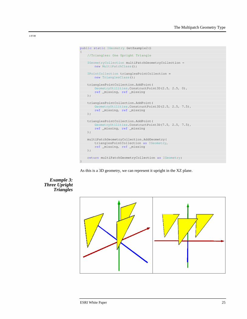
As this is a 3D geometry, we can represent it upright in the XZ plane.
Example 3: Three Upright
Triangles

The Multipatch Geometry Type
J-9749
December 2008 26
public static IGeometry GetExample3() { //Triangles: Three Upright Triangles IGeometryCollection multiPatchGeometryCollection = new MultiPatchClass(); IPointCollection trianglesPointCollection = new TrianglesClass(); //Triangle 1 trianglesPointCollection.AddPoint( GeometryUtilities.ConstructPoint3D(2.5, 2.5, 0), ref _missing, ref _missing ); trianglesPointCollection.AddPoint( GeometryUtilities.ConstructPoint3D(2.5, 2.5, 7.5), ref _missing, ref _missing ); trianglesPointCollection.AddPoint( GeometryUtilities.ConstructPoint3D(7.5, 2.5, 7.5), ref _missing, ref _missing ); //Triangle 2 trianglesPointCollection.AddPoint( GeometryUtilities.ConstructPoint3D(-7.5, 2.5, 0), ref _missing, ref _missing ); trianglesPointCollection.AddPoint( GeometryUtilities.ConstructPoint3D(-7.5, 2.5, 7.5), ref _missing, ref _missing ); trianglesPointCollection.AddPoint( GeometryUtilities.ConstructPoint3D(-2.5, 2.5, 7.5), ref _missing, ref _missing ); //Triangle 3 trianglesPointCollection.AddPoint( GeometryUtilities.ConstructPoint3D(-2.5, -2.5, 0), ref _missing, ref _missing ); trianglesPointCollection.AddPoint( GeometryUtilities.ConstructPoint3D(-2.5, -2.5, 7.5), ref _missing, ref _missing ); trianglesPointCollection.AddPoint( GeometryUtilities.ConstructPoint3D(2.5, -2.5, 7.5), ref _missing, ref _missing );
The Multipatch Geometry Type
J-9749
ESRI White Paper 27
multiPatchGeometryCollection.AddGeometry( trianglesPointCollection as IGeometry, ref _missing, ref _missing ); return multiPatchGeometryCollection as IGeometry; }
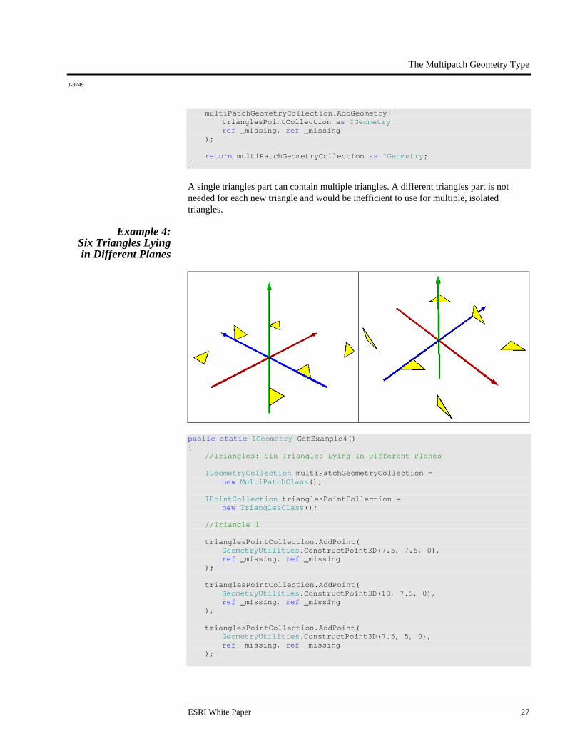
A single triangles part can contain multiple triangles. A different triangles part is not needed for each new triangle and would be inefficient to use for multiple, isolated triangles.
Example 4: Six Triangles Lying in Different Planes
public static IGeometry GetExample4() { //Triangles: Six Triangles Lying In Different Planes IGeometryCollection multiPatchGeometryCollection = new MultiPatchClass(); IPointCollection trianglesPointCollection = new TrianglesClass(); //Triangle 1 trianglesPointCollection.AddPoint( GeometryUtilities.ConstructPoint3D(7.5, 7.5, 0), ref _missing, ref _missing ); trianglesPointCollection.AddPoint( GeometryUtilities.ConstructPoint3D(10, 7.5, 0), ref _missing, ref _missing ); trianglesPointCollection.AddPoint( GeometryUtilities.ConstructPoint3D(7.5, 5, 0), ref _missing, ref _missing );

The Multipatch Geometry Type
J-9749
December 2008 28
//Triangle 2 trianglesPointCollection.AddPoint( GeometryUtilities.ConstructPoint3D(-7.5, 7.5, 0), ref _missing, ref _missing ); trianglesPointCollection.AddPoint( GeometryUtilities.ConstructPoint3D(-5, 7.5, 0), ref _missing, ref _missing ); trianglesPointCollection.AddPoint( GeometryUtilities.ConstructPoint3D(-7.5, 5, 0), ref _missing, ref _missing ); //Triangle 3 trianglesPointCollection.AddPoint( GeometryUtilities.ConstructPoint3D(0, -5, 0), ref _missing, ref _missing ); trianglesPointCollection.AddPoint( GeometryUtilities.ConstructPoint3D(2.5, -5, 0), ref _missing, ref _missing ); trianglesPointCollection.AddPoint( GeometryUtilities.ConstructPoint3D(0, -7.5, 0), ref _missing, ref _missing ); //Triangle 4 trianglesPointCollection.AddPoint( GeometryUtilities.ConstructPoint3D(0, 7.5, 2.5), ref _missing, ref _missing ); trianglesPointCollection.AddPoint( GeometryUtilities.ConstructPoint3D(2.5, 7.5, 0), ref _missing, ref _missing ); trianglesPointCollection.AddPoint( GeometryUtilities.ConstructPoint3D(0, 7.5, 0), ref _missing, ref _missing ); //Triangle 5 trianglesPointCollection.AddPoint( GeometryUtilities.ConstructPoint3D(-7.5, -7.5, 2.5), ref _missing, ref _missing ); trianglesPointCollection.AddPoint( GeometryUtilities.ConstructPoint3D(-5, -7.5, 0), ref _missing, ref _missing );
The Multipatch Geometry Type
J-9749
ESRI White Paper 29
trianglesPointCollection.AddPoint( GeometryUtilities.ConstructPoint3D(-7.5, -7.5, 0), ref _missing, ref _missing ); //Triangle 6 trianglesPointCollection.AddPoint( GeometryUtilities.ConstructPoint3D(7.5, -7.5, 2.5), ref _missing, ref _missing ); trianglesPointCollection.AddPoint( GeometryUtilities.ConstructPoint3D(10, -7.5, 0), ref _missing, ref _missing ); trianglesPointCollection.AddPoint( GeometryUtilities.ConstructPoint3D(7.5, -7.5, 0), ref _missing, ref _missing ); multiPatchGeometryCollection.AddGeometry( trianglesPointCollection as IGeometry, ref _missing, ref _missing ); return multiPatchGeometryCollection as IGeometry; }
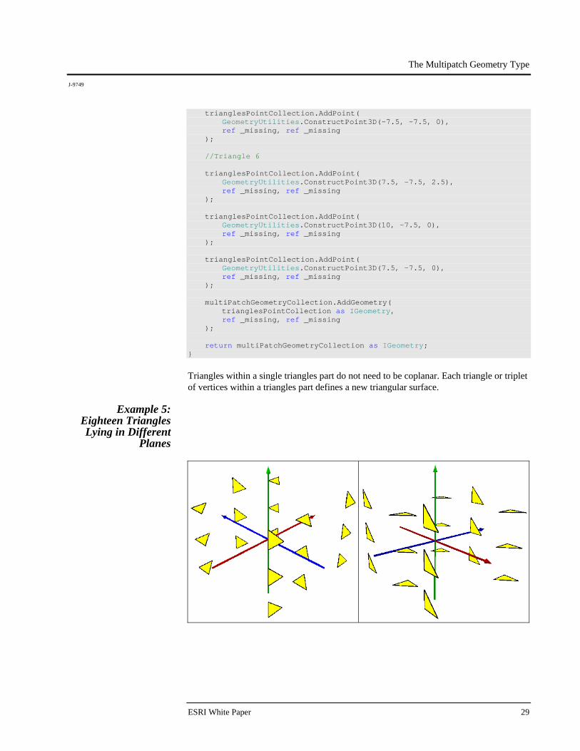
Triangles within a single triangles part do not need to be coplanar. Each triangle or triplet of vertices within a triangles part defines a new triangular surface.
Example 5: Eighteen Triangles Lying in Different
Planes

The Multipatch Geometry Type
J-9749
December 2008 30
public static IGeometry GetExample5() { //Triangles: Eighteen Triangles Lying In Different Planes IGeometryCollection multiPatchGeometryCollection = new MultiPatchClass(); IPointCollection trianglesPointCollection = new TrianglesClass(); //Z > 0 //Triangle 1 trianglesPointCollection.AddPoint( GeometryUtilities.ConstructPoint3D(7.5, 7.5, 5), ref _missing, ref _missing ); trianglesPointCollection.AddPoint( GeometryUtilities.ConstructPoint3D(10, 7.5, 5), ref _missing, ref _missing ); trianglesPointCollection.AddPoint( GeometryUtilities.ConstructPoint3D(7.5, 5, 5), ref _missing, ref _missing ); //Triangle 2 trianglesPointCollection.AddPoint( GeometryUtilities.ConstructPoint3D(-7.5, 7.5, 5), ref _missing, ref _missing ); trianglesPointCollection.AddPoint( GeometryUtilities.ConstructPoint3D(-5, 7.5, 5), ref _missing, ref _missing ); trianglesPointCollection.AddPoint( GeometryUtilities.ConstructPoint3D(-7.5, 5, 5), ref _missing, ref _missing ); //Triangle 3 trianglesPointCollection.AddPoint( GeometryUtilities.ConstructPoint3D(0, -5, 5), ref _missing, ref _missing ); trianglesPointCollection.AddPoint( GeometryUtilities.ConstructPoint3D(2.5, -5, 5), ref _missing, ref _missing ); trianglesPointCollection.AddPoint( GeometryUtilities.ConstructPoint3D(0, -7.5, 5), ref _missing, ref _missing );
The Multipatch Geometry Type
J-9749
ESRI White Paper 31
//Triangle 4 trianglesPointCollection.AddPoint( GeometryUtilities.ConstructPoint3D(0, 7.5, 7.5), ref _missing, ref _missing ); trianglesPointCollection.AddPoint( GeometryUtilities.ConstructPoint3D(2.5, 7.5, 5), ref _missing, ref _missing ); trianglesPointCollection.AddPoint( GeometryUtilities.ConstructPoint3D(0, 7.5, 5), ref _missing, ref _missing ); //Triangle 5 trianglesPointCollection.AddPoint( GeometryUtilities.ConstructPoint3D(-7.5, -7.5, 7.5), ref _missing, ref _missing ); trianglesPointCollection.AddPoint( GeometryUtilities.ConstructPoint3D(-5, -7.5, 5), ref _missing, ref _missing ); trianglesPointCollection.AddPoint( GeometryUtilities.ConstructPoint3D(-7.5, -7.5, 5), ref _missing, ref _missing ); //Triangle 6 trianglesPointCollection.AddPoint( GeometryUtilities.ConstructPoint3D(7.5, -7.5, 7.5), ref _missing, ref _missing ); trianglesPointCollection.AddPoint( GeometryUtilities.ConstructPoint3D(10, -7.5, 5), ref _missing, ref _missing ); trianglesPointCollection.AddPoint( GeometryUtilities.ConstructPoint3D(7.5, -7.5, 5), ref _missing, ref _missing ); //Z = 0 //Triangle 1 trianglesPointCollection.AddPoint( GeometryUtilities.ConstructPoint3D(7.5, 7.5, 0), ref _missing, ref _missing ); trianglesPointCollection.AddPoint( GeometryUtilities.ConstructPoint3D(10, 7.5, 0), ref _missing, ref _missing );

The Multipatch Geometry Type
J-9749
December 2008 32
trianglesPointCollection.AddPoint( GeometryUtilities.ConstructPoint3D(7.5, 5, 0), ref _missing, ref _missing ); //Triangle 2 trianglesPointCollection.AddPoint( GeometryUtilities.ConstructPoint3D(-7.5, 7.5, 0), ref _missing, ref _missing ); trianglesPointCollection.AddPoint( GeometryUtilities.ConstructPoint3D(-5, 7.5, 0), ref _missing, ref _missing ); trianglesPointCollection.AddPoint( GeometryUtilities.ConstructPoint3D(-7.5, 5, 0), ref _missing, ref _missing ); //Triangle 3 trianglesPointCollection.AddPoint( GeometryUtilities.ConstructPoint3D(0, -5, 0), ref _missing, ref _missing ); trianglesPointCollection.AddPoint( GeometryUtilities.ConstructPoint3D(2.5, -5, 0), ref _missing, ref _missing ); trianglesPointCollection.AddPoint( GeometryUtilities.ConstructPoint3D(0, -7.5, 0), ref _missing, ref _missing ); //Triangle 4 trianglesPointCollection.AddPoint( GeometryUtilities.ConstructPoint3D(0, 7.5, 2.5), ref _missing, ref _missing ); trianglesPointCollection.AddPoint( GeometryUtilities.ConstructPoint3D(2.5, 7.5, 0), ref _missing, ref _missing ); trianglesPointCollection.AddPoint( GeometryUtilities.ConstructPoint3D(0, 7.5, 0), ref _missing, ref _missing ); //Triangle 5 trianglesPointCollection.AddPoint( GeometryUtilities.ConstructPoint3D(-7.5, -7.5, 2.5), ref _missing, ref _missing );
The Multipatch Geometry Type
J-9749
ESRI White Paper 33
trianglesPointCollection.AddPoint( GeometryUtilities.ConstructPoint3D(-5, -7.5, 0), ref _missing, ref _missing ); trianglesPointCollection.AddPoint( GeometryUtilities.ConstructPoint3D(-7.5, -7.5, 0), ref _missing, ref _missing ); //Triangle 6 trianglesPointCollection.AddPoint( GeometryUtilities.ConstructPoint3D(7.5, -7.5, 2.5), ref _missing, ref _missing ); trianglesPointCollection.AddPoint( GeometryUtilities.ConstructPoint3D(10, -7.5, 0), ref _missing, ref _missing ); trianglesPointCollection.AddPoint( GeometryUtilities.ConstructPoint3D(7.5, -7.5, 0), ref _missing, ref _missing ); //Z < 0 //Triangle 1 trianglesPointCollection.AddPoint( GeometryUtilities.ConstructPoint3D(7.5, 7.5, -5), ref _missing, ref _missing ); trianglesPointCollection.AddPoint( GeometryUtilities.ConstructPoint3D(10, 7.5, -5), ref _missing, ref _missing ); trianglesPointCollection.AddPoint( GeometryUtilities.ConstructPoint3D(7.5, 5, -5), ref _missing, ref _missing ); //Triangle 2 trianglesPointCollection.AddPoint( GeometryUtilities.ConstructPoint3D(-7.5, 7.5, -5), ref _missing, ref _missing ); trianglesPointCollection.AddPoint( GeometryUtilities.ConstructPoint3D(-5, 7.5, -5), ref _missing, ref _missing ); trianglesPointCollection.AddPoint( GeometryUtilities.ConstructPoint3D(-7.5, 5, -5), ref _missing, ref _missing );

The Multipatch Geometry Type
J-9749
December 2008 34
//Triangle 3 trianglesPointCollection.AddPoint( GeometryUtilities.ConstructPoint3D(0, -5, -5), ref _missing, ref _missing ); trianglesPointCollection.AddPoint( GeometryUtilities.ConstructPoint3D(2.5, -5, -5), ref _missing, ref _missing ); trianglesPointCollection.AddPoint( GeometryUtilities.ConstructPoint3D(0, -7.5, -5), ref _missing, ref _missing ); //Triangle 4 trianglesPointCollection.AddPoint( GeometryUtilities.ConstructPoint3D(0, 7.5, -2.5), ref _missing, ref _missing ); trianglesPointCollection.AddPoint( GeometryUtilities.ConstructPoint3D(2.5, 7.5, -5), ref _missing, ref _missing ); trianglesPointCollection.AddPoint( GeometryUtilities.ConstructPoint3D(0, 7.5, -5), ref _missing, ref _missing ); //Triangle 5 trianglesPointCollection.AddPoint( GeometryUtilities.ConstructPoint3D(-7.5, -7.5, -2.5), ref _missing, ref _missing ); trianglesPointCollection.AddPoint( GeometryUtilities.ConstructPoint3D(-5, -7.5, -5), ref _missing, ref _missing ); trianglesPointCollection.AddPoint( GeometryUtilities.ConstructPoint3D(-7.5, -7.5, -5), ref _missing, ref _missing ); //Triangle 6 trianglesPointCollection.AddPoint( GeometryUtilities.ConstructPoint3D(7.5, -7.5, -2.5), ref _missing, ref _missing ); trianglesPointCollection.AddPoint( GeometryUtilities.ConstructPoint3D(10, -7.5, -5), ref _missing, ref _missing );
The Multipatch Geometry Type
J-9749
ESRI White Paper 35
trianglesPointCollection.AddPoint( GeometryUtilities.ConstructPoint3D(7.5, -7.5, -5), ref _missing, ref _missing ); multiPatchGeometryCollection.AddGeometry( trianglesPointCollection as IGeometry, ref _missing, ref _missing ); return multiPatchGeometryCollection as IGeometry; }
This example builds on the previous one, showing that triangles can be rendered above, at, and below a given z level, in this case z = 0. It also illustrates how large numbers of disjoint triangle geometries output by a 3D tessellator can be conveniently captured into a single multipatch part.
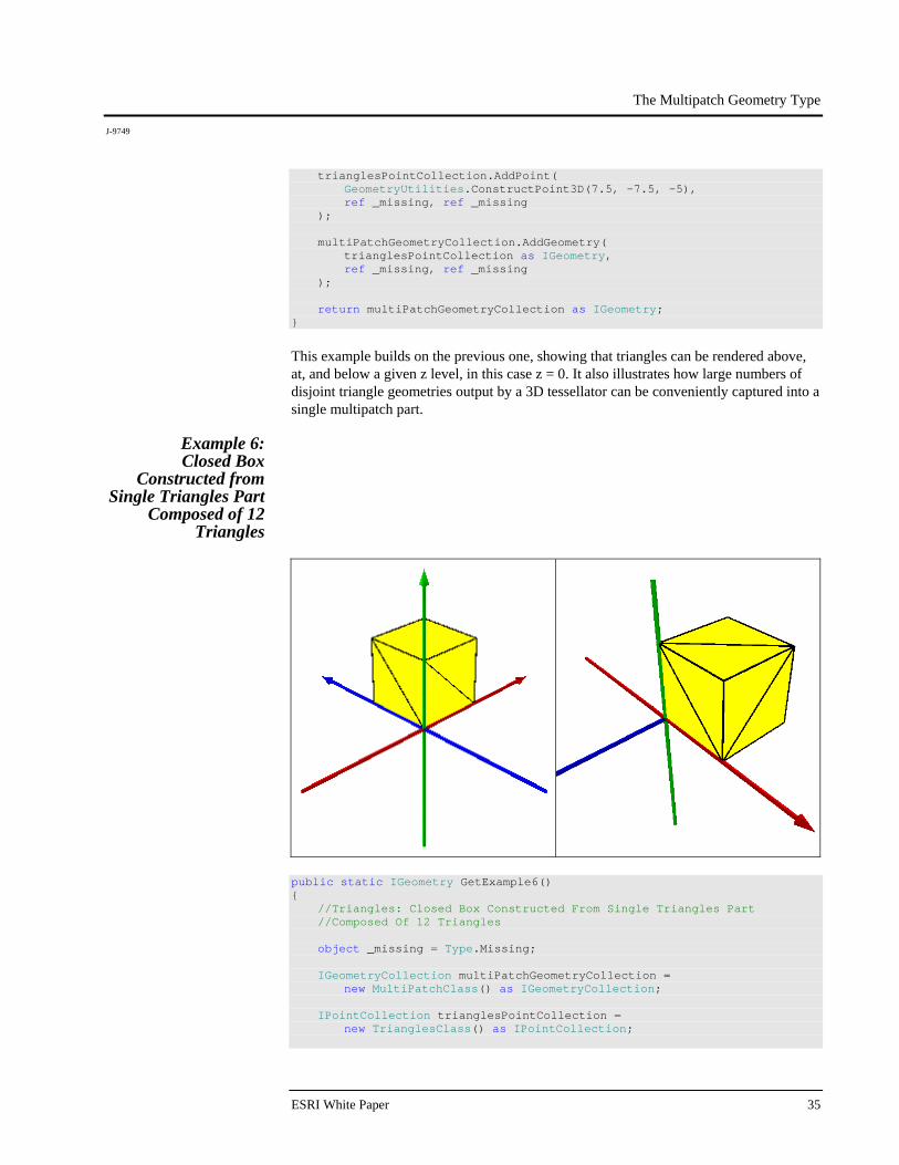
Example 6: Closed Box
Constructed from Single Triangles Part
Composed of 12 Triangles
public static IGeometry GetExample6() { //Triangles: Closed Box Constructed From Single Triangles Part //Composed Of 12 Triangles object _missing = Type.Missing; IGeometryCollection multiPatchGeometryCollection = new MultiPatchClass() as IGeometryCollection; IPointCollection trianglesPointCollection = new TrianglesClass() as IPointCollection;

The Multipatch Geometry Type
J-9749
December 2008 36
//Bottom trianglesPointCollection.AddPoint( GeometryUtilities.ConstructPoint3D(0, 0, 0), ref _missing, ref _missing ); trianglesPointCollection.AddPoint( GeometryUtilities.ConstructPoint3D(5, 5, 0), ref _missing, ref _missing ); trianglesPointCollection.AddPoint( GeometryUtilities.ConstructPoint3D(0, 5, 0), ref _missing, ref _missing ); trianglesPointCollection.AddPoint( GeometryUtilities.ConstructPoint3D(0, 0, 0), ref _missing, ref _missing ); trianglesPointCollection.AddPoint( GeometryUtilities.ConstructPoint3D(5, 0, 0), ref _missing, ref _missing ); trianglesPointCollection.AddPoint( GeometryUtilities.ConstructPoint3D(5, 5, 0), ref _missing, ref _missing ); //Side 1 trianglesPointCollection.AddPoint( GeometryUtilities.ConstructPoint3D(0, 5, 0), ref _missing, ref _missing ); trianglesPointCollection.AddPoint( GeometryUtilities.ConstructPoint3D(0, 5, 5), ref _missing, ref _missing ); trianglesPointCollection.AddPoint( GeometryUtilities.ConstructPoint3D(0, 0, 0), ref _missing, ref _missing ); trianglesPointCollection.AddPoint( GeometryUtilities.ConstructPoint3D(0, 0, 0), ref _missing, ref _missing ); trianglesPointCollection.AddPoint( GeometryUtilities.ConstructPoint3D(0, 5, 5), ref _missing, ref _missing ); trianglesPointCollection.AddPoint( GeometryUtilities.ConstructPoint3D(0, 0, 5), ref _missing, ref _missing );
The Multipatch Geometry Type
J-9749
ESRI White Paper 37
//Side 2 trianglesPointCollection.AddPoint( GeometryUtilities.ConstructPoint3D(5, 5, 0), ref _missing, ref _missing ); trianglesPointCollection.AddPoint( GeometryUtilities.ConstructPoint3D(0, 5, 5), ref _missing, ref _missing ); trianglesPointCollection.AddPoint( GeometryUtilities.ConstructPoint3D(0, 5, 0), ref _missing, ref _missing ); trianglesPointCollection.AddPoint( GeometryUtilities.ConstructPoint3D(5, 5, 0), ref _missing, ref _missing ); trianglesPointCollection.AddPoint( GeometryUtilities.ConstructPoint3D(5, 5, 5), ref _missing, ref _missing ); trianglesPointCollection.AddPoint( GeometryUtilities.ConstructPoint3D(0, 5, 5), ref _missing, ref _missing ); //Side 3 trianglesPointCollection.AddPoint( GeometryUtilities.ConstructPoint3D(5, 0, 0), ref _missing, ref _missing ); trianglesPointCollection.AddPoint( GeometryUtilities.ConstructPoint3D(5, 5, 5), ref _missing, ref _missing ); trianglesPointCollection.AddPoint( GeometryUtilities.ConstructPoint3D(5, 5, 0), ref _missing, ref _missing ); trianglesPointCollection.AddPoint( GeometryUtilities.ConstructPoint3D(5, 0, 0), ref _missing, ref _missing ); trianglesPointCollection.AddPoint( GeometryUtilities.ConstructPoint3D(5, 0, 5), ref _missing, ref _missing ); trianglesPointCollection.AddPoint( GeometryUtilities.ConstructPoint3D(5, 5, 5), ref _missing, ref _missing );

The Multipatch Geometry Type
J-9749
December 2008 38
//Side 4 trianglesPointCollection.AddPoint( GeometryUtilities.ConstructPoint3D(0, 0, 0), ref _missing, ref _missing ); trianglesPointCollection.AddPoint( GeometryUtilities.ConstructPoint3D(0, 0, 5), ref _missing, ref _missing ); trianglesPointCollection.AddPoint( GeometryUtilities.ConstructPoint3D(5, 0, 0), ref _missing, ref _missing ); trianglesPointCollection.AddPoint( GeometryUtilities.ConstructPoint3D(5, 0, 0), ref _missing, ref _missing ); trianglesPointCollection.AddPoint( GeometryUtilities.ConstructPoint3D(0, 0, 5), ref _missing, ref _missing ); trianglesPointCollection.AddPoint( GeometryUtilities.ConstructPoint3D(5, 0, 5), ref _missing, ref _missing ); //Top trianglesPointCollection.AddPoint( GeometryUtilities.ConstructPoint3D(0, 0, 5), ref _missing, ref _missing ); trianglesPointCollection.AddPoint( GeometryUtilities.ConstructPoint3D(0, 5, 5), ref _missing, ref _missing ); trianglesPointCollection.AddPoint( GeometryUtilities.ConstructPoint3D(5, 5, 5), ref _missing, ref _missing ); trianglesPointCollection.AddPoint( GeometryUtilities.ConstructPoint3D(0, 0, 5), ref _missing, ref _missing ); trianglesPointCollection.AddPoint( GeometryUtilities.ConstructPoint3D(5, 5, 5), ref _missing, ref _missing ); trianglesPointCollection.AddPoint( GeometryUtilities.ConstructPoint3D(5, 0, 5), ref _missing, ref _missing );
The Multipatch Geometry Type
J-9749
ESRI White Paper 39
multiPatchGeometryCollection.AddGeometry( trianglesPointCollection as IGeometry, ref _missing, ref _missing ); return multiPatchGeometryCollection as IGeometry; }
A single triangles part can also be used to form a closed solid. In this example, a closed box is constructed from 12 triangles participating in a single triangles part.
Ring Examples
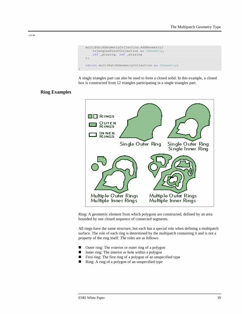
Ring: A geometric element from which polygons are constructed, defined by an area bounded by one closed sequence of connected segments. All rings have the same structure, but each has a special role when defining a multipatch surface. The role of each ring is determined by the multipatch containing it and is not a property of the ring itself. The roles are as follows:
Outer ring: The exterior or outer ring of a polygon Inner ring: The interior or hole within a polygon First ring: The first ring of a polygon of an unspecified type Ring: A ring of a polygon of an unspecified type
The Multipatch Geometry Type
J-9749
December 2008 40
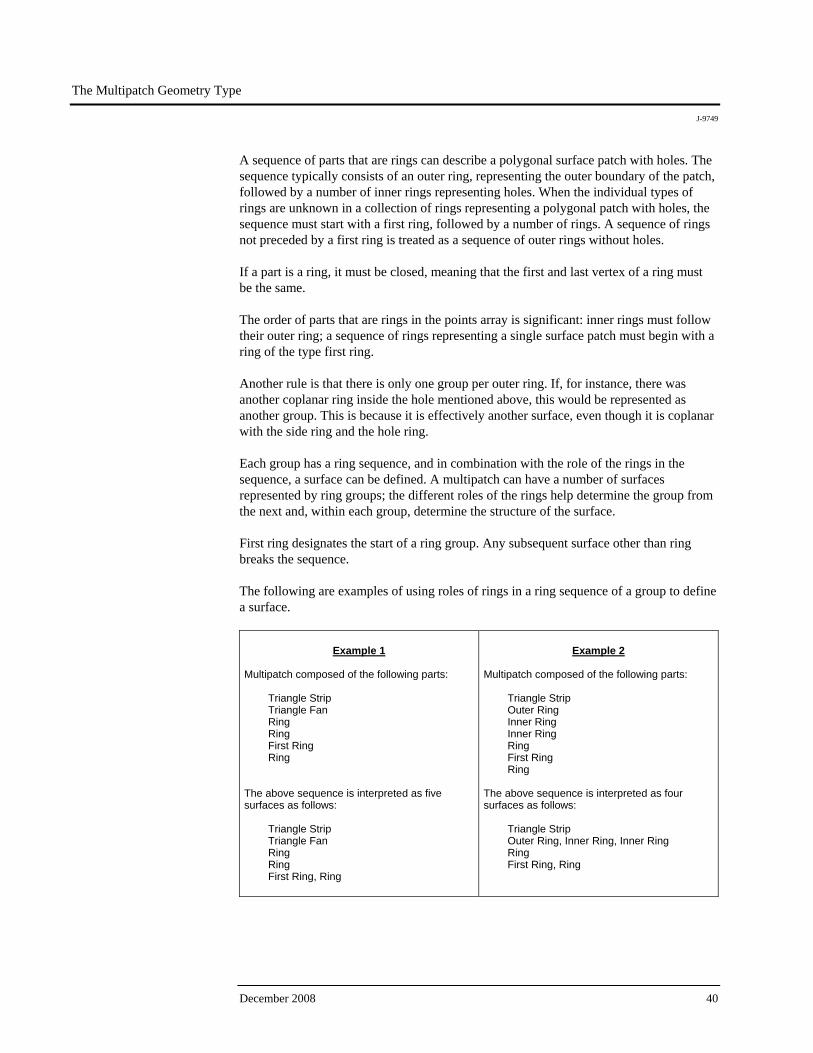
A sequence of parts that are rings can describe a polygonal surface patch with holes. The sequence typically consists of an outer ring, representing the outer boundary of the patch, followed by a number of inner rings representing holes. When the individual types of rings are unknown in a collection of rings representing a polygonal patch with holes, the sequence must start with a first ring, followed by a number of rings. A sequence of rings not preceded by a first ring is treated as a sequence of outer rings without holes. If a part is a ring, it must be closed, meaning that the first and last vertex of a ring must be the same. The order of parts that are rings in the points array is significant: inner rings must follow their outer ring; a sequence of rings representing a single surface patch must begin with a ring of the type first ring. Another rule is that there is only one group per outer ring. If, for instance, there was another coplanar ring inside the hole mentioned above, this would be represented as another group. This is because it is effectively another surface, even though it is coplanar with the side ring and the hole ring. Each group has a ring sequence, and in combination with the role of the rings in the sequence, a surface can be defined. A multipatch can have a number of surfaces represented by ring groups; the different roles of the rings help determine the group from the next and, within each group, determine the structure of the surface. First ring designates the start of a ring group. Any subsequent surface other than ring breaks the sequence. The following are examples of using roles of rings in a ring sequence of a group to define a surface.
Example 1 Multipatch composed of the following parts:
Triangle Strip Triangle Fan Ring Ring First Ring Ring
The above sequence is interpreted as five surfaces as follows:
Triangle Strip Triangle Fan Ring Ring First Ring, Ring
Example 2
Multipatch composed of the following parts:
Triangle Strip Outer Ring Inner Ring Inner Ring Ring First Ring Ring
The above sequence is interpreted as four surfaces as follows:
Triangle Strip Outer Ring, Inner Ring, Inner Ring Ring First Ring, Ring
The Multipatch Geometry Type
J-9749
ESRI White Paper 41
Outer ring/inner ring nomenclature is a more structured form for representing a surface than first ring/ring series. The former explicitly defines that any inner ring that immediately follows an outer ring is a hole in the outer ring. In the sequence, inner must always follow outer or inner. Otherwise, it would be an error. Anything other than inner would stop the sequence for the inner/outer group. This paper will focus on outer (exterior) rings and inner (interior) rings, as it is possible to represent every type of ring patch using these two roles alone. In cases in which a multipatch is defined using rings with no holes or interiors, the basic ring role is used for convenience, although outer ring would work just as well.
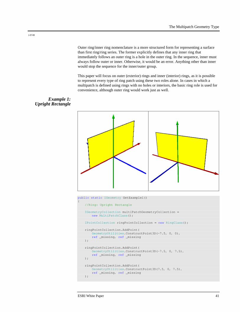
Example 1: Upright Rectangle
public static IGeometry GetExample1() { //Ring: Upright Rectangle IGeometryCollection multiPatchGeometryCollection = new MultiPatchClass(); IPointCollection ringPointCollection = new RingClass(); ringPointCollection.AddPoint( GeometryUtilities.ConstructPoint3D(-7.5, 0, 0), ref _missing, ref _missing ); ringPointCollection.AddPoint( GeometryUtilities.ConstructPoint3D(-7.5, 0, 7.5), ref _missing, ref _missing ); ringPointCollection.AddPoint( GeometryUtilities.ConstructPoint3D(7.5, 0, 7.5), ref _missing, ref _missing );
The Multipatch Geometry Type
J-9749
December 2008 42
ringPointCollection.AddPoint( GeometryUtilities.ConstructPoint3D(7.5, 0, 0), ref _missing, ref _missing ); ringPointCollection.AddPoint( GeometryUtilities.ConstructPoint3D(-7.5, 0, 0), ref _missing, ref _missing ); multiPatchGeometryCollection.AddGeometry( ringPointCollection as IGeometry, ref _missing, ref _missing ); return multiPatchGeometryCollection as IGeometry; }
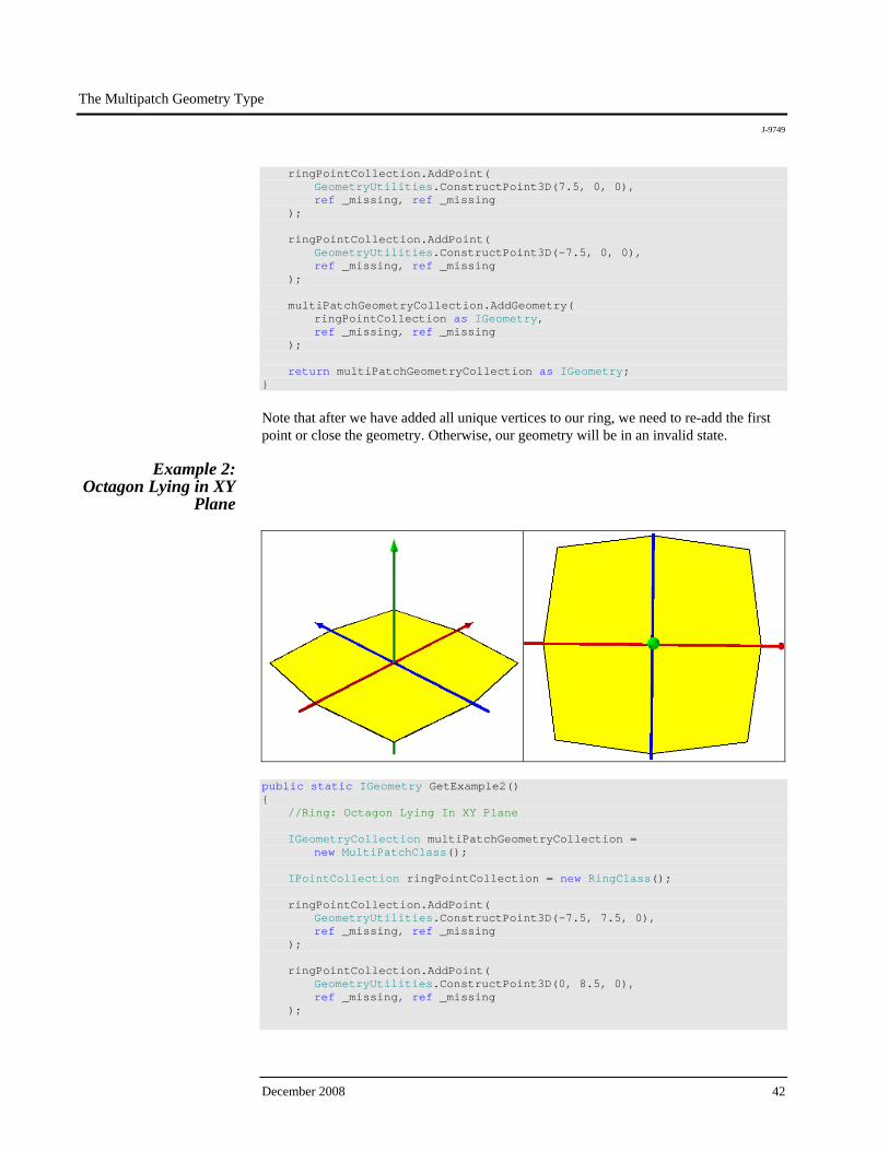
Note that after we have added all unique vertices to our ring, we need to re-add the first point or close the geometry. Otherwise, our geometry will be in an invalid state.
Example 2: Octagon Lying in XY
Plane
public static IGeometry GetExample2() { //Ring: Octagon Lying In XY Plane IGeometryCollection multiPatchGeometryCollection = new MultiPatchClass(); IPointCollection ringPointCollection = new RingClass(); ringPointCollection.AddPoint( GeometryUtilities.ConstructPoint3D(-7.5, 7.5, 0), ref _missing, ref _missing ); ringPointCollection.AddPoint( GeometryUtilities.ConstructPoint3D(0, 8.5, 0), ref _missing, ref _missing );
The Multipatch Geometry Type
J-9749
ESRI White Paper 43
ringPointCollection.AddPoint( GeometryUtilities.ConstructPoint3D(7.5, 7.5, 0), ref _missing, ref _missing ); ringPointCollection.AddPoint( GeometryUtilities.ConstructPoint3D(8.5, 0, 0), ref _missing, ref _missing ); ringPointCollection.AddPoint( GeometryUtilities.ConstructPoint3D(7.5, -7.5, 0), ref _missing, ref _missing ); ringPointCollection.AddPoint( GeometryUtilities.ConstructPoint3D(0, -8.5, 0), ref _missing, ref _missing ); ringPointCollection.AddPoint( GeometryUtilities.ConstructPoint3D(-7.5, -7.5, 0), ref _missing, ref _missing ); ringPointCollection.AddPoint( GeometryUtilities.ConstructPoint3D(-8.5, 0, 0), ref _missing, ref _missing ); ringPointCollection.AddPoint( GeometryUtilities.ConstructPoint3D(-7.5, 7.5, 0), ref _missing, ref _missing ); multiPatchGeometryCollection.AddGeometry( ringPointCollection as IGeometry, ref _missing, ref _missing ); return multiPatchGeometryCollection as IGeometry; }
The Multipatch Geometry Type
J-9749
December 2008 44
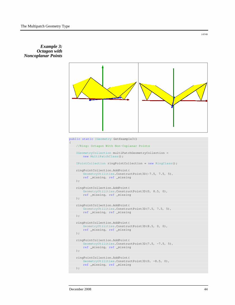
Example 3: Octagon with
Noncoplanar Points
public static IGeometry GetExample3() { //Ring: Octagon With Non-Coplanar Points IGeometryCollection multiPatchGeometryCollection = new MultiPatchClass(); IPointCollection ringPointCollection = new RingClass(); ringPointCollection.AddPoint( GeometryUtilities.ConstructPoint3D(-7.5, 7.5, 5), ref _missing, ref _missing ); ringPointCollection.AddPoint( GeometryUtilities.ConstructPoint3D(0, 8.5, 0), ref _missing, ref _missing ); ringPointCollection.AddPoint( GeometryUtilities.ConstructPoint3D(7.5, 7.5, 5), ref _missing, ref _missing ); ringPointCollection.AddPoint( GeometryUtilities.ConstructPoint3D(8.5, 0, 0), ref _missing, ref _missing ); ringPointCollection.AddPoint( GeometryUtilities.ConstructPoint3D(7.5, -7.5, 5), ref _missing, ref _missing ); ringPointCollection.AddPoint( GeometryUtilities.ConstructPoint3D(0, -8.5, 0), ref _missing, ref _missing );
The Multipatch Geometry Type
J-9749
ESRI White Paper 45
ringPointCollection.AddPoint( GeometryUtilities.ConstructPoint3D(-7.5, -7.5, 5), ref _missing, ref _missing ); ringPointCollection.AddPoint( GeometryUtilities.ConstructPoint3D(-8.5, 0, 0), ref _missing, ref _missing ); ringPointCollection.AddPoint( GeometryUtilities.ConstructPoint3D(-7.5, 7.5, 5), ref _missing, ref _missing ); multiPatchGeometryCollection.AddGeometry( ringPointCollection as IGeometry, ref _missing, ref _missing ); return multiPatchGeometryCollection as IGeometry; }
This example illustrates the effect of setting our ring vertices to have differing z-values. Because such rings with noncoplanar vertices can be represented and rendered differently than we may expect, it is a good idea to adhere to the rule of only constructing rings with coplanar points. If we really desired the resulting geometry, for example, we could represent it with a single triangle strip for the center and a single triangles part for the two triangles on both ends.
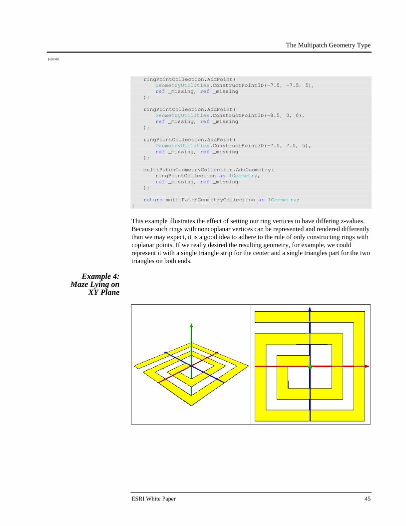
Example 4: Maze Lying on
XY Plane

The Multipatch Geometry Type
J-9749
December 2008 46
public static IGeometry GetExample4() { //Ring: Maze Lying On XY Plane IGeometryCollection multiPatchGeometryCollection = new MultiPatchClass(); IPointCollection ringPointCollection = new RingClass(); ringPointCollection.AddPoint( GeometryUtilities.ConstructPoint3D(-10, 10, 0), ref _missing, ref _missing ); ringPointCollection.AddPoint( GeometryUtilities.ConstructPoint3D(10, 10, 0), ref _missing, ref _missing ); ringPointCollection.AddPoint( GeometryUtilities.ConstructPoint3D(10, -10, 0), ref _missing, ref _missing ); ringPointCollection.AddPoint( GeometryUtilities.ConstructPoint3D(-10, -10, 0), ref _missing, ref _missing ); ringPointCollection.AddPoint( GeometryUtilities.ConstructPoint3D(-10, 6, 0), ref _missing, ref _missing ); ringPointCollection.AddPoint( GeometryUtilities.ConstructPoint3D(6, 6, 0), ref _missing, ref _missing ); ringPointCollection.AddPoint( GeometryUtilities.ConstructPoint3D(6, -6, 0), ref _missing, ref _missing ); ringPointCollection.AddPoint( GeometryUtilities.ConstructPoint3D(-6, -6, 0), ref _missing, ref _missing ); ringPointCollection.AddPoint( GeometryUtilities.ConstructPoint3D(-6, 2, 0), ref _missing, ref _missing ); ringPointCollection.AddPoint( GeometryUtilities.ConstructPoint3D(-6, 2, 0), ref _missing, ref _missing ); ringPointCollection.AddPoint( GeometryUtilities.ConstructPoint3D(0, 2, 0), ref _missing, ref _missing );

The Multipatch Geometry Type
J-9749
ESRI White Paper 47
ringPointCollection.AddPoint( GeometryUtilities.ConstructPoint3D(0, 0, 0), ref _missing, ref _missing ); ringPointCollection.AddPoint( GeometryUtilities.ConstructPoint3D(-4, 0, 0), ref _missing, ref _missing ); ringPointCollection.AddPoint( GeometryUtilities.ConstructPoint3D(-4, -4, 0), ref _missing, ref _missing ); ringPointCollection.AddPoint( GeometryUtilities.ConstructPoint3D(4, -4, 0), ref _missing, ref _missing ); ringPointCollection.AddPoint( GeometryUtilities.ConstructPoint3D(4, 4, 0), ref _missing, ref _missing ); ringPointCollection.AddPoint( GeometryUtilities.ConstructPoint3D(-8, 4, 0), ref _missing, ref _missing ); ringPointCollection.AddPoint( GeometryUtilities.ConstructPoint3D(-8, -8, 0), ref _missing, ref _missing ); ringPointCollection.AddPoint( GeometryUtilities.ConstructPoint3D(8, -8, 0), ref _missing, ref _missing ); ringPointCollection.AddPoint( GeometryUtilities.ConstructPoint3D(8, 8, 0), ref _missing, ref _missing ); ringPointCollection.AddPoint( GeometryUtilities.ConstructPoint3D(-10, 8, 0), ref _missing, ref _missing ); ringPointCollection.AddPoint( GeometryUtilities.ConstructPoint3D(-10, 10, 0), ref _missing, ref _missing ); multiPatchGeometryCollection.AddGeometry( ringPointCollection as IGeometry, ref _missing, ref _missing ); return multiPatchGeometryCollection as IGeometry; }
The Multipatch Geometry Type
J-9749
December 2008 48
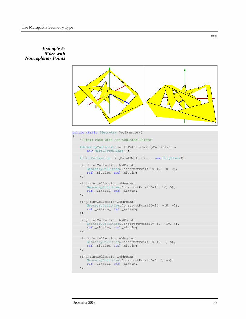
Example 5: Maze with
Noncoplanar Points
public static IGeometry GetExample5() { //Ring: Maze With Non-Coplanar Points IGeometryCollection multiPatchGeometryCollection = new MultiPatchClass(); IPointCollection ringPointCollection = new RingClass(); ringPointCollection.AddPoint( GeometryUtilities.ConstructPoint3D(-10, 10, 0), ref _missing, ref _missing ); ringPointCollection.AddPoint( GeometryUtilities.ConstructPoint3D(10, 10, 5), ref _missing, ref _missing ); ringPointCollection.AddPoint( GeometryUtilities.ConstructPoint3D(10, -10, -5), ref _missing, ref _missing ); ringPointCollection.AddPoint( GeometryUtilities.ConstructPoint3D(-10, -10, 0), ref _missing, ref _missing ); ringPointCollection.AddPoint( GeometryUtilities.ConstructPoint3D(-10, 6, 5), ref _missing, ref _missing ); ringPointCollection.AddPoint( GeometryUtilities.ConstructPoint3D(6, 6, -5), ref _missing, ref _missing );

The Multipatch Geometry Type
J-9749
ESRI White Paper 49
ringPointCollection.AddPoint( GeometryUtilities.ConstructPoint3D(6, -6, 0), ref _missing, ref _missing ); ringPointCollection.AddPoint( GeometryUtilities.ConstructPoint3D(-6, -6, 5), ref _missing, ref _missing ); ringPointCollection.AddPoint( GeometryUtilities.ConstructPoint3D(-6, 2, -5), ref _missing, ref _missing ); ringPointCollection.AddPoint( GeometryUtilities.ConstructPoint3D(-6, 2, 0), ref _missing, ref _missing ); ringPointCollection.AddPoint( GeometryUtilities.ConstructPoint3D(0, 2, 5), ref _missing, ref _missing ); ringPointCollection.AddPoint( GeometryUtilities.ConstructPoint3D(0, 0, -5), ref _missing, ref _missing ); ringPointCollection.AddPoint( GeometryUtilities.ConstructPoint3D(-4, 0, 0), ref _missing, ref _missing ); ringPointCollection.AddPoint( GeometryUtilities.ConstructPoint3D(-4, -4, 5), ref _missing, ref _missing ); ringPointCollection.AddPoint( GeometryUtilities.ConstructPoint3D(4, -4, -5), ref _missing, ref _missing ); ringPointCollection.AddPoint( GeometryUtilities.ConstructPoint3D(4, 4, 0), ref _missing, ref _missing ); ringPointCollection.AddPoint( GeometryUtilities.ConstructPoint3D(-8, 4, 5), ref _missing, ref _missing ); ringPointCollection.AddPoint( GeometryUtilities.ConstructPoint3D(-8, -8, -5), ref _missing, ref _missing ); ringPointCollection.AddPoint( GeometryUtilities.ConstructPoint3D(8, -8, 0), ref _missing, ref _missing );
The Multipatch Geometry Type
J-9749
December 2008 50
ringPointCollection.AddPoint( GeometryUtilities.ConstructPoint3D(8, 8, 5), ref _missing, ref _missing ); ringPointCollection.AddPoint( GeometryUtilities.ConstructPoint3D(-10, 8, -5), ref _missing, ref _missing ); ringPointCollection.AddPoint( GeometryUtilities.ConstructPoint3D(-10, 10, 0), ref _missing, ref _missing ); multiPatchGeometryCollection.AddGeometry( ringPointCollection as IGeometry, ref _missing, ref _missing ); return multiPatchGeometryCollection as IGeometry; }
This somewhat more complex example of a ring with noncoplanar points further emphasizes the importance of adhering to the above mentioned rule.
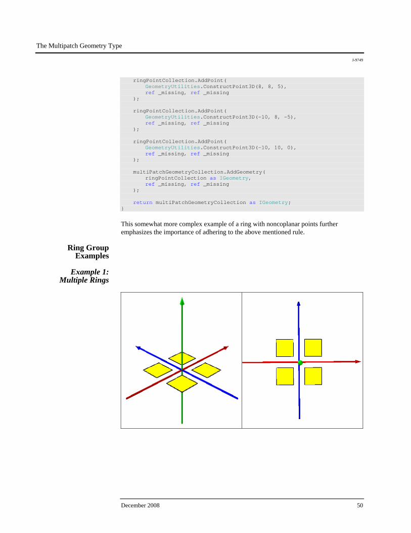
Ring Group Examples
Example 1:
Multiple Rings
The Multipatch Geometry Type
J-9749
ESRI White Paper 51
public static IGeometry GetExample1() { //RingGroup: Multiple Rings IGeometryCollection multiPatchGeometryCollection = new MultiPatchClass(); //Ring 1 IPointCollection ring1PointCollection = new RingClass(); ring1PointCollection.AddPoint( GeometryUtilities.ConstructPoint3D(1, 1, 0), ref _missing, ref _missing ); ring1PointCollection.AddPoint( GeometryUtilities.ConstructPoint3D(1, 4, 0), ref _missing, ref _missing ); ring1PointCollection.AddPoint( GeometryUtilities.ConstructPoint3D(4, 4, 0), ref _missing, ref _missing ); ring1PointCollection.AddPoint( GeometryUtilities.ConstructPoint3D(4, 1, 0), ref _missing, ref _missing ); IRing ring1 = ring1PointCollection as IRing; ring1.Close(); multiPatchGeometryCollection.AddGeometry( ring1 as IGeometry, ref _missing, ref _missing ); //Ring 2 IPointCollection ring2PointCollection = new RingClass(); ring2PointCollection.AddPoint( GeometryUtilities.ConstructPoint3D(1, -1, 0), ref _missing, ref _missing ); ring2PointCollection.AddPoint( GeometryUtilities.ConstructPoint3D(4, -1, 0), ref _missing, ref _missing ); ring2PointCollection.AddPoint( GeometryUtilities.ConstructPoint3D(4, -4, 0), ref _missing, ref _missing ); ring2PointCollection.AddPoint( GeometryUtilities.ConstructPoint3D(1, -4, 0), ref _missing, ref _missing );
The Multipatch Geometry Type
J-9749
December 2008 52
IRing ring2 = ring2PointCollection as IRing; ring2.Close(); multiPatchGeometryCollection.AddGeometry( ring2 as IGeometry, ref _missing, ref _missing ); //Ring 3 IPointCollection ring3PointCollection = new RingClass(); ring3PointCollection.AddPoint( GeometryUtilities.ConstructPoint3D(-1, 1, 0), ref _missing, ref _missing ); ring3PointCollection.AddPoint( GeometryUtilities.ConstructPoint3D(-4, 1, 0), ref _missing, ref _missing ); ring3PointCollection.AddPoint( GeometryUtilities.ConstructPoint3D(-4, 4, 0), ref _missing, ref _missing ); ring3PointCollection.AddPoint( GeometryUtilities.ConstructPoint3D(-1, 4, 0), ref _missing, ref _missing ); IRing ring3 = ring3PointCollection as IRing; ring3.Close(); multiPatchGeometryCollection.AddGeometry( ring3 as IGeometry, ref _missing, ref _missing ); //Ring 4 IPointCollection ring4PointCollection = new RingClass(); ring4PointCollection.AddPoint( GeometryUtilities.ConstructPoint3D(-1, -1, 0), ref _missing, ref _missing ); ring4PointCollection.AddPoint( GeometryUtilities.ConstructPoint3D(-1, -4, 0), ref _missing, ref _missing ); ring4PointCollection.AddPoint( GeometryUtilities.ConstructPoint3D(-4, -4, 0), ref _missing, ref _missing ); ring4PointCollection.AddPoint( GeometryUtilities.ConstructPoint3D(-4, -1, 0), ref _missing, ref _missing );
The Multipatch Geometry Type
J-9749
ESRI White Paper 53
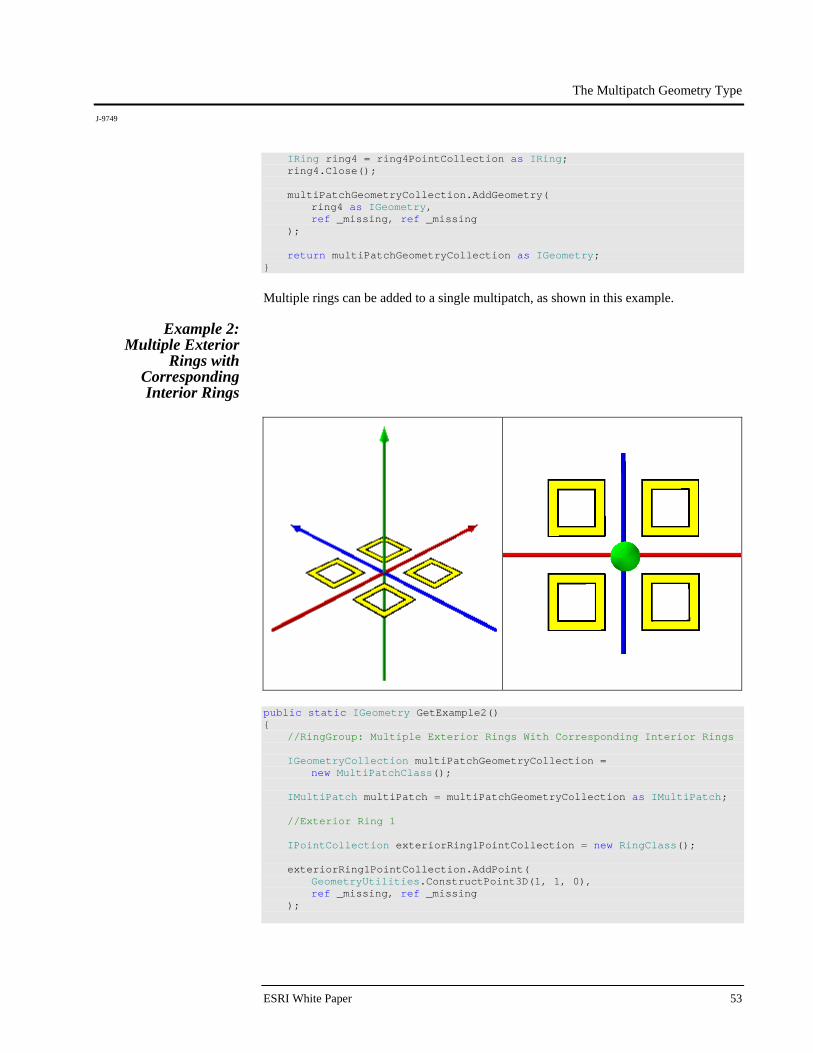
IRing ring4 = ring4PointCollection as IRing; ring4.Close(); multiPatchGeometryCollection.AddGeometry( ring4 as IGeometry, ref _missing, ref _missing ); return multiPatchGeometryCollection as IGeometry; }
Multiple rings can be added to a single multipatch, as shown in this example.
Example 2: Multiple Exterior
Rings with Corresponding Interior Rings
public static IGeometry GetExample2() { //RingGroup: Multiple Exterior Rings With Corresponding Interior Rings IGeometryCollection multiPatchGeometryCollection = new MultiPatchClass(); IMultiPatch multiPatch = multiPatchGeometryCollection as IMultiPatch; //Exterior Ring 1 IPointCollection exteriorRing1PointCollection = new RingClass(); exteriorRing1PointCollection.AddPoint( GeometryUtilities.ConstructPoint3D(1, 1, 0), ref _missing, ref _missing );
The Multipatch Geometry Type
J-9749
December 2008 54
exteriorRing1PointCollection.AddPoint( GeometryUtilities.ConstructPoint3D(1, 4, 0), ref _missing, ref _missing ); exteriorRing1PointCollection.AddPoint( GeometryUtilities.ConstructPoint3D(4, 4, 0), ref _missing, ref _missing ); exteriorRing1PointCollection.AddPoint( GeometryUtilities.ConstructPoint3D(4, 1, 0), ref _missing, ref _missing ); IRing exteriorRing1 = exteriorRing1PointCollection as IRing; exteriorRing1.Close(); multiPatchGeometryCollection.AddGeometry( exteriorRing1 as IGeometry, ref _missing, ref _missing ); multiPatch.PutRingType( exteriorRing1, esriMultiPatchRingType.esriMultiPatchOuterRing ); //Interior Ring 1 IPointCollection interiorRing1PointCollection = new RingClass(); interiorRing1PointCollection.AddPoint( GeometryUtilities.ConstructPoint3D(3.5, 1.5, 0), ref _missing, ref _missing ); interiorRing1PointCollection.AddPoint( GeometryUtilities.ConstructPoint3D(3.5, 3.5, 0), ref _missing, ref _missing ); interiorRing1PointCollection.AddPoint( GeometryUtilities.ConstructPoint3D(1.5, 3.5, 0), ref _missing, ref _missing ); interiorRing1PointCollection.AddPoint( GeometryUtilities.ConstructPoint3D(1.5, 1.5, 0), ref _missing, ref _missing ); IRing interiorRing1 = interiorRing1PointCollection as IRing; interiorRing1.Close(); multiPatchGeometryCollection.AddGeometry( interiorRing1 as IGeometry, ref _missing, ref _missing ); multiPatch.PutRingType( interiorRing1, esriMultiPatchRingType.esriMultiPatchInnerRing );

The Multipatch Geometry Type
J-9749
ESRI White Paper 55
//Exterior Ring 2 IPointCollection exteriorRing2PointCollection = new RingClass(); exteriorRing2PointCollection.AddPoint( GeometryUtilities.ConstructPoint3D(1, -1, 0), ref _missing, ref _missing ); exteriorRing2PointCollection.AddPoint( GeometryUtilities.ConstructPoint3D(4, -1, 0), ref _missing, ref _missing ); exteriorRing2PointCollection.AddPoint( GeometryUtilities.ConstructPoint3D(4, -4, 0), ref _missing, ref _missing ); exteriorRing2PointCollection.AddPoint( GeometryUtilities.ConstructPoint3D(1, -4, 0), ref _missing, ref _missing ); IRing exteriorRing2 = exteriorRing2PointCollection as IRing; exteriorRing2.Close(); multiPatchGeometryCollection.AddGeometry( exteriorRing2 as IGeometry, ref _missing, ref _missing ); multiPatch.PutRingType( exteriorRing2, esriMultiPatchRingType.esriMultiPatchOuterRing ); //Interior Ring 2 IPointCollection interiorRing2PointCollection = new RingClass(); interiorRing2PointCollection.AddPoint( GeometryUtilities.ConstructPoint3D(1.5, -1.5, 0), ref _missing, ref _missing ); interiorRing2PointCollection.AddPoint( GeometryUtilities.ConstructPoint3D(3.5, -1.5, 0), ref _missing, ref _missing ); interiorRing2PointCollection.AddPoint( GeometryUtilities.ConstructPoint3D(3.5, -3.5, 0), ref _missing, ref _missing ); interiorRing2PointCollection.AddPoint( GeometryUtilities.ConstructPoint3D(1.5, -3.5, 0), ref _missing, ref _missing );

The Multipatch Geometry Type
J-9749
December 2008 56
IRing interiorRing2 = interiorRing2PointCollection as IRing; interiorRing2.Close(); multiPatchGeometryCollection.AddGeometry( interiorRing2 as IGeometry, ref _missing, ref _missing ); multiPatch.PutRingType( interiorRing2, esriMultiPatchRingType.esriMultiPatchInnerRing ); //Exterior Ring 3 IPointCollection exteriorRing3PointCollection = new RingClass(); exteriorRing3PointCollection.AddPoint( GeometryUtilities.ConstructPoint3D(-1, 1, 0), ref _missing, ref _missing ); exteriorRing3PointCollection.AddPoint( GeometryUtilities.ConstructPoint3D(-4, 1, 0), ref _missing, ref _missing ); exteriorRing3PointCollection.AddPoint( GeometryUtilities.ConstructPoint3D(-4, 4, 0), ref _missing, ref _missing ); exteriorRing3PointCollection.AddPoint( GeometryUtilities.ConstructPoint3D(-1, 4, 0), ref _missing, ref _missing ); IRing exteriorRing3 = exteriorRing3PointCollection as IRing; exteriorRing3.Close(); multiPatchGeometryCollection.AddGeometry( exteriorRing3 as IGeometry, ref _missing, ref _missing ); multiPatch.PutRingType( exteriorRing3, esriMultiPatchRingType.esriMultiPatchOuterRing ); //Interior Ring 3 IPointCollection interiorRing3PointCollection = new RingClass(); interiorRing3PointCollection.AddPoint( GeometryUtilities.ConstructPoint3D(-1.5, 1.5, 0), ref _missing, ref _missing ); interiorRing3PointCollection.AddPoint( GeometryUtilities.ConstructPoint3D(-3.5, 1.5, 0), ref _missing, ref _missing );

The Multipatch Geometry Type
J-9749
ESRI White Paper 57
interiorRing3PointCollection.AddPoint( GeometryUtilities.ConstructPoint3D(-3.5, 3.5, 0), ref _missing, ref _missing ); interiorRing3PointCollection.AddPoint( GeometryUtilities.ConstructPoint3D(-1.5, 3.5, 0), ref _missing, ref _missing ); IRing interiorRing3 = interiorRing3PointCollection as IRing; interiorRing3.Close(); multiPatchGeometryCollection.AddGeometry( interiorRing3 as IGeometry, ref _missing, ref _missing ); multiPatch.PutRingType( interiorRing3, esriMultiPatchRingType.esriMultiPatchInnerRing ); //Exterior Ring 4 IPointCollection exteriorRing4PointCollection = new RingClass(); exteriorRing4PointCollection.AddPoint( GeometryUtilities.ConstructPoint3D(-1, -1, 0), ref _missing, ref _missing ); exteriorRing4PointCollection.AddPoint( GeometryUtilities.ConstructPoint3D(-1, -4, 0), ref _missing, ref _missing ); exteriorRing4PointCollection.AddPoint( GeometryUtilities.ConstructPoint3D(-4, -4, 0), ref _missing, ref _missing ); exteriorRing4PointCollection.AddPoint( GeometryUtilities.ConstructPoint3D(-4, -1, 0), ref _missing, ref _missing ); IRing exteriorRing4 = exteriorRing4PointCollection as IRing; exteriorRing4.Close(); multiPatchGeometryCollection.AddGeometry( exteriorRing4 as IGeometry, ref _missing, ref _missing ); multiPatch.PutRingType( exteriorRing4, esriMultiPatchRingType.esriMultiPatchOuterRing );

The Multipatch Geometry Type
J-9749
December 2008 58
//Interior Ring 4 IPointCollection interiorRing4PointCollection = new RingClass(); interiorRing4PointCollection.AddPoint( GeometryUtilities.ConstructPoint3D(-1.5, -1.5, 0), ref _missing, ref _missing ); interiorRing4PointCollection.AddPoint( GeometryUtilities.ConstructPoint3D(-1.5, -3.5, 0), ref _missing, ref _missing ); interiorRing4PointCollection.AddPoint( GeometryUtilities.ConstructPoint3D(-3.5, -3.5, 0), ref _missing, ref _missing ); interiorRing4PointCollection.AddPoint( GeometryUtilities.ConstructPoint3D(-3.5, -1.5, 0), ref _missing, ref _missing ); IRing interiorRing4 = interiorRing4PointCollection as IRing; interiorRing4.Close(); multiPatchGeometryCollection.AddGeometry( interiorRing4 as IGeometry, ref _missing, ref _missing ); multiPatch.PutRingType( interiorRing4, esriMultiPatchRingType.esriMultiPatchInnerRing ); return multiPatchGeometryCollection as IGeometry; }
By adding exterior rings, then corresponding interior rings in sequence, we are able to generate a hole effect. To accomplish this, we must use the IMultiPatch interface to specify the appropriate ring type:
Constant Value Description esriMultiPatchInvalidRing 1 Invalid Ring. esriMultiPatchUndefinedRing 2 Ring type has not been defined. esriMultiPatchFirstRing 4 The beginning FirstRing in a FirstRing/Ring
sequence. esriMultiPatchRing 8 A following Ring in a FirstRing/Ring sequence or
a beginning Ring in a solo Ring group. esriMultiPatchOuterRing 16 The beginning OuterRing in an
OuterRing/InnerRing sequence. esriMultiPatchInnerRing 32 A following InnerRing in an OuterRing/InnerRing
sequence. esriMultiPatchBeginningRingMask 28 A mask of valid beginning rings (OuterRings,
FirstRings, and solo Rings). esriMultiPatchFollowingRingMask 40 A mask of valid following rings (InnerRings and
Rings). esriMultiPatchProblemCaseRingMask 3 A mask of problematic rings (UndefinedRings
and InvalidRings).
The Multipatch Geometry Type
J-9749
ESRI White Paper 59
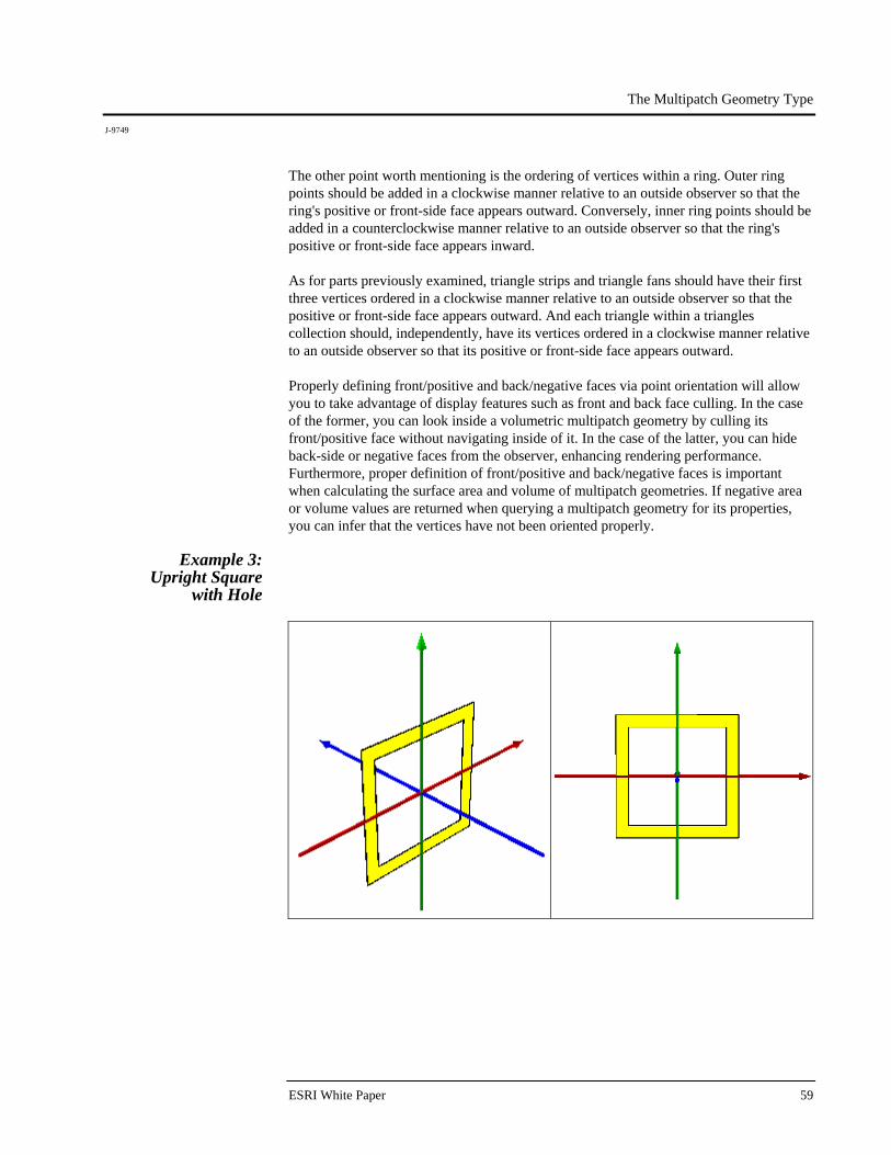
The other point worth mentioning is the ordering of vertices within a ring. Outer ring points should be added in a clockwise manner relative to an outside observer so that the ring's positive or front-side face appears outward. Conversely, inner ring points should be added in a counterclockwise manner relative to an outside observer so that the ring's positive or front-side face appears inward. As for parts previously examined, triangle strips and triangle fans should have their first three vertices ordered in a clockwise manner relative to an outside observer so that the positive or front-side face appears outward. And each triangle within a triangles collection should, independently, have its vertices ordered in a clockwise manner relative to an outside observer so that its positive or front-side face appears outward. Properly defining front/positive and back/negative faces via point orientation will allow you to take advantage of display features such as front and back face culling. In the case of the former, you can look inside a volumetric multipatch geometry by culling its front/positive face without navigating inside of it. In the case of the latter, you can hide back-side or negative faces from the observer, enhancing rendering performance. Furthermore, proper definition of front/positive and back/negative faces is important when calculating the surface area and volume of multipatch geometries. If negative area or volume values are returned when querying a multipatch geometry for its properties, you can infer that the vertices have not been oriented properly.
Example 3: Upright Square
with Hole

The Multipatch Geometry Type
J-9749
December 2008 60
public static IGeometry GetExample3() { //RingGroup: Upright Square With Hole IGeometryCollection multiPatchGeometryCollection = new MultiPatchClass(); IMultiPatch multiPatch = multiPatchGeometryCollection as IMultiPatch; //Exterior Ring 1 IPointCollection exteriorRing1PointCollection = new RingClass(); exteriorRing1PointCollection.AddPoint( GeometryUtilities.ConstructPoint3D(5, 0, -5), ref _missing, ref _missing ); exteriorRing1PointCollection.AddPoint( GeometryUtilities.ConstructPoint3D(-5, 0, -5), ref _missing, ref _missing ); exteriorRing1PointCollection.AddPoint( GeometryUtilities.ConstructPoint3D(-5, 0, 5), ref _missing, ref _missing ); exteriorRing1PointCollection.AddPoint( GeometryUtilities.ConstructPoint3D(5, 0, 5), ref _missing, ref _missing ); IRing exteriorRing1 = exteriorRing1PointCollection as IRing; exteriorRing1.Close(); multiPatchGeometryCollection.AddGeometry( exteriorRing1 as IGeometry, ref _missing, ref _missing ); multiPatch.PutRingType( exteriorRing1, esriMultiPatchRingType.esriMultiPatchOuterRing ); //Interior Ring 1 IPointCollection interiorRing1PointCollection = new RingClass(); interiorRing1PointCollection.AddPoint( GeometryUtilities.ConstructPoint3D(-4, 0, -4), ref _missing, ref _missing ); interiorRing1PointCollection.AddPoint( GeometryUtilities.ConstructPoint3D(4, 0, -4), ref _missing, ref _missing ); interiorRing1PointCollection.AddPoint( GeometryUtilities.ConstructPoint3D(4, 0, 4), ref _missing, ref _missing );
The Multipatch Geometry Type
J-9749
ESRI White Paper 61
interiorRing1PointCollection.AddPoint( GeometryUtilities.ConstructPoint3D(-4, 0, 4), ref _missing, ref _missing ); IRing interiorRing1 = interiorRing1PointCollection as IRing; interiorRing1.Close(); multiPatchGeometryCollection.AddGeometry( interiorRing1 as IGeometry, ref _missing, ref _missing ); multiPatch.PutRingType( interiorRing1, esriMultiPatchRingType.esriMultiPatchInnerRing ); return multiPatchGeometryCollection as IGeometry; }
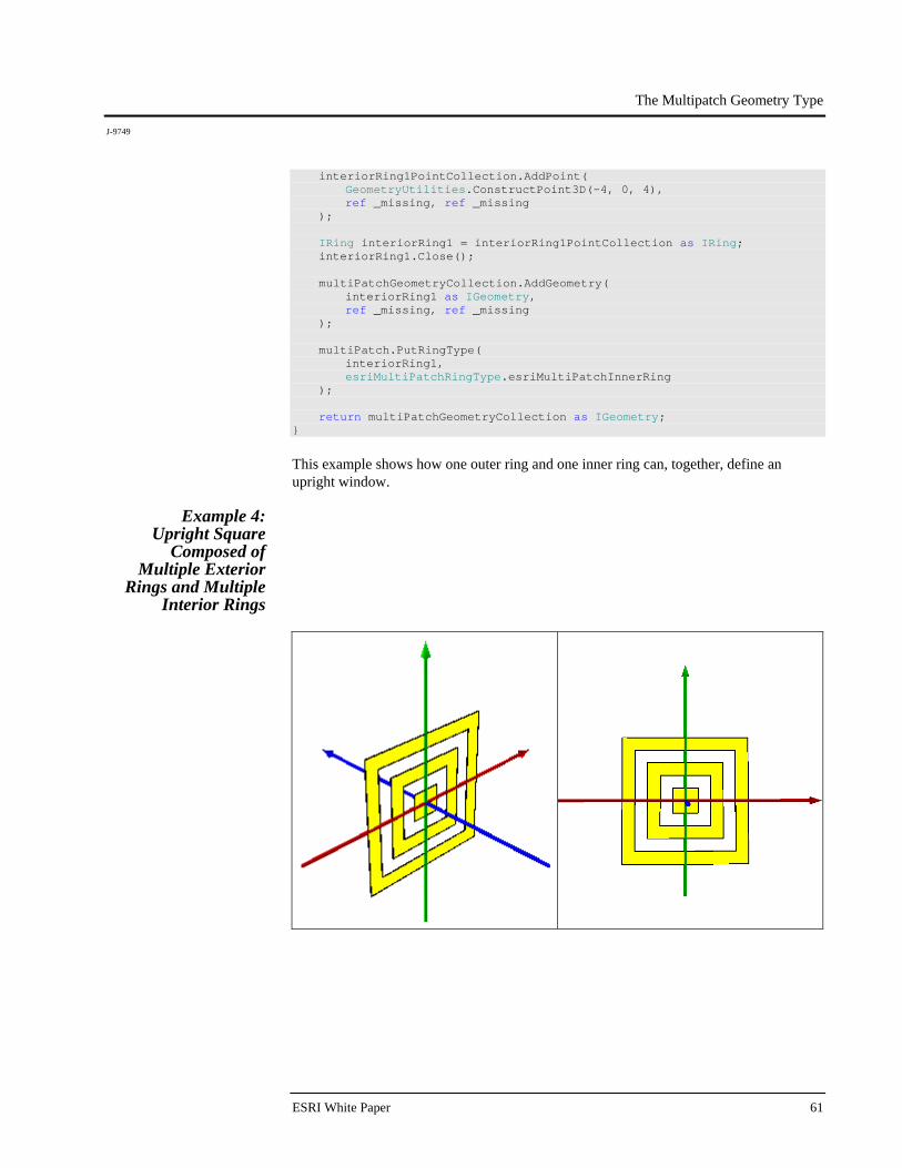
This example shows how one outer ring and one inner ring can, together, define an upright window.
Example 4: Upright Square
Composed of Multiple Exterior
Rings and Multiple Interior Rings

The Multipatch Geometry Type
J-9749
December 2008 62
public static IGeometry GetExample4() { //RingGroup: Upright Square Composed Of Multiple Exterior Rings //And Multiple Interior Rings IGeometryCollection multiPatchGeometryCollection = new MultiPatchClass(); IMultiPatch multiPatch = multiPatchGeometryCollection as IMultiPatch; //Exterior Ring 1 IPointCollection exteriorRing1PointCollection = new RingClass(); exteriorRing1PointCollection.AddPoint( GeometryUtilities.ConstructPoint3D(5, 0, -5), ref _missing, ref _missing ); exteriorRing1PointCollection.AddPoint( GeometryUtilities.ConstructPoint3D(-5, 0, -5), ref _missing, ref _missing ); exteriorRing1PointCollection.AddPoint( GeometryUtilities.ConstructPoint3D(-5, 0, 5), ref _missing, ref _missing ); exteriorRing1PointCollection.AddPoint( GeometryUtilities.ConstructPoint3D(5, 0, 5), ref _missing, ref _missing ); IRing exteriorRing1 = exteriorRing1PointCollection as IRing; exteriorRing1.Close(); multiPatchGeometryCollection.AddGeometry( exteriorRing1 as IGeometry, ref _missing, ref _missing ); multiPatch.PutRingType( exteriorRing1, esriMultiPatchRingType.esriMultiPatchOuterRing ); //Interior Ring 1 IPointCollection interiorRing1PointCollection = new RingClass(); interiorRing1PointCollection.AddPoint( GeometryUtilities.ConstructPoint3D(-4, 0, -4), ref _missing, ref _missing ); interiorRing1PointCollection.AddPoint( GeometryUtilities.ConstructPoint3D(4, 0, -4), ref _missing, ref _missing ); interiorRing1PointCollection.AddPoint( GeometryUtilities.ConstructPoint3D(4, 0, 4), ref _missing, ref _missing );

The Multipatch Geometry Type
J-9749
ESRI White Paper 63
interiorRing1PointCollection.AddPoint( GeometryUtilities.ConstructPoint3D(-4, 0, 4), ref _missing, ref _missing ); IRing interiorRing1 = interiorRing1PointCollection as IRing; interiorRing1.Close(); multiPatchGeometryCollection.AddGeometry( interiorRing1 as IGeometry, ref _missing, ref _missing ); multiPatch.PutRingType( interiorRing1, esriMultiPatchRingType.esriMultiPatchInnerRing ); //Exterior Ring 2 IPointCollection exteriorRing2PointCollection = new RingClass(); exteriorRing2PointCollection.AddPoint( GeometryUtilities.ConstructPoint3D(3, 0, -3), ref _missing, ref _missing ); exteriorRing2PointCollection.AddPoint( GeometryUtilities.ConstructPoint3D(-3, 0, -3), ref _missing, ref _missing ); exteriorRing2PointCollection.AddPoint( GeometryUtilities.ConstructPoint3D(-3, 0, 3), ref _missing, ref _missing ); exteriorRing2PointCollection.AddPoint( GeometryUtilities.ConstructPoint3D(3, 0, 3), ref _missing, ref _missing ); IRing exteriorRing2 = exteriorRing2PointCollection as IRing; exteriorRing2.Close(); multiPatchGeometryCollection.AddGeometry( exteriorRing2 as IGeometry, ref _missing, ref _missing ); multiPatch.PutRingType( exteriorRing2, esriMultiPatchRingType.esriMultiPatchOuterRing ); //Interior Ring 2 IPointCollection interiorRing2PointCollection = new RingClass(); interiorRing2PointCollection.AddPoint( GeometryUtilities.ConstructPoint3D(-2, 0, -2), ref _missing, ref _missing );
The Multipatch Geometry Type
J-9749
December 2008 64
interiorRing2PointCollection.AddPoint( GeometryUtilities.ConstructPoint3D(2, 0, -2), ref _missing, ref _missing ); interiorRing2PointCollection.AddPoint( GeometryUtilities.ConstructPoint3D(2, 0, 2), ref _missing, ref _missing ); interiorRing2PointCollection.AddPoint( GeometryUtilities.ConstructPoint3D(-2, 0, 2), ref _missing, ref _missing ); IRing interiorRing2 = interiorRing2PointCollection as IRing; interiorRing2.Close(); multiPatchGeometryCollection.AddGeometry( interiorRing2 as IGeometry, ref _missing, ref _missing ); multiPatch.PutRingType( interiorRing2, esriMultiPatchRingType.esriMultiPatchInnerRing ); //Exterior Ring 3 IPointCollection exteriorRing3PointCollection = new RingClass(); exteriorRing3PointCollection.AddPoint( GeometryUtilities.ConstructPoint3D(1, 0, -1), ref _missing, ref _missing ); exteriorRing3PointCollection.AddPoint( GeometryUtilities.ConstructPoint3D(-1, 0, -1), ref _missing, ref _missing ); exteriorRing3PointCollection.AddPoint( GeometryUtilities.ConstructPoint3D(-1, 0, 1), ref _missing, ref _missing ); exteriorRing3PointCollection.AddPoint( GeometryUtilities.ConstructPoint3D(1, 0, 1), ref _missing, ref _missing ); IRing exteriorRing3 = exteriorRing3PointCollection as IRing; exteriorRing3.Close(); multiPatchGeometryCollection.AddGeometry( exteriorRing3 as IGeometry, ref _missing, ref _missing );
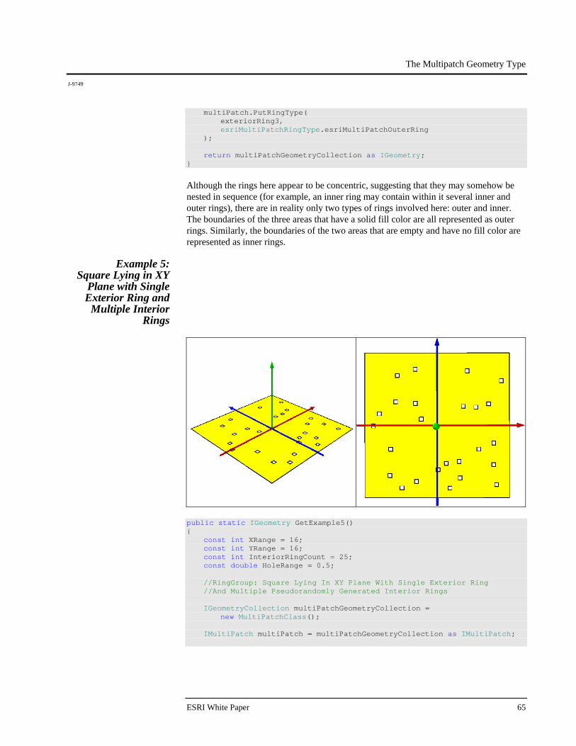
The Multipatch Geometry Type
J-9749
ESRI White Paper 65
multiPatch.PutRingType( exteriorRing3, esriMultiPatchRingType.esriMultiPatchOuterRing ); return multiPatchGeometryCollection as IGeometry; }
Although the rings here appear to be concentric, suggesting that they may somehow be nested in sequence (for example, an inner ring may contain within it several inner and outer rings), there are in reality only two types of rings involved here: outer and inner. The boundaries of the three areas that have a solid fill color are all represented as outer rings. Similarly, the boundaries of the two areas that are empty and have no fill color are represented as inner rings.
Example 5: Square Lying in XY
Plane with Single Exterior Ring and
Multiple Interior Rings
public static IGeometry GetExample5() { const int XRange = 16; const int YRange = 16; const int InteriorRingCount = 25; const double HoleRange = 0.5; //RingGroup: Square Lying In XY Plane With Single Exterior Ring //And Multiple Pseudorandomly Generated Interior Rings IGeometryCollection multiPatchGeometryCollection = new MultiPatchClass(); IMultiPatch multiPatch = multiPatchGeometryCollection as IMultiPatch;
The Multipatch Geometry Type
J-9749
December 2008 66
//Exterior Ring IPointCollection exteriorRingPointCollection = new RingClass(); exteriorRingPointCollection.AddPoint( GeometryUtilities.ConstructPoint3D( 0.5 * (XRange + 2), -0.5 * (YRange + 2), 0 ), ref _missing, ref _missing ); exteriorRingPointCollection.AddPoint( GeometryUtilities.ConstructPoint3D( -0.5 * (XRange + 2), -0.5 * (YRange + 2), 0 ), ref _missing, ref _missing ); exteriorRingPointCollection.AddPoint( GeometryUtilities.ConstructPoint3D( -0.5 * (XRange + 2), 0.5 * (YRange + 2), 0 ), ref _missing, ref _missing ); exteriorRingPointCollection.AddPoint( GeometryUtilities.ConstructPoint3D( 0.5 * (XRange + 2), 0.5 * (YRange + 2), 0 ), ref _missing, ref _missing ); IRing exteriorRing = exteriorRingPointCollection as IRing; exteriorRing.Close(); multiPatchGeometryCollection.AddGeometry( exteriorRing as IGeometry, ref _missing, ref _missing ); multiPatch.PutRingType( exteriorRing, esriMultiPatchRingType.esriMultiPatchOuterRing ); //Interior Rings Random random = new Random(); for (int i = 0; i < InteriorRingCount; i++) { double interiorRingOriginX = XRange * (random.NextDouble() - 0.5); double interiorRingOriginY = YRange * (random.NextDouble() - 0.5); IPointCollection interiorRingPointCollection = new RingClass();
The Multipatch Geometry Type
J-9749
ESRI White Paper 67
interiorRingPointCollection.AddPoint( GeometryUtilities.ConstructPoint3D( interiorRingOriginX - 0.5 * HoleRange, interiorRingOriginY - 0.5 * HoleRange, 0 ), ref _missing, ref _missing ); interiorRingPointCollection.AddPoint( GeometryUtilities.ConstructPoint3D( interiorRingOriginX + 0.5 * HoleRange, interiorRingOriginY - 0.5 * HoleRange, 0 ), ref _missing, ref _missing ); interiorRingPointCollection.AddPoint( GeometryUtilities.ConstructPoint3D( interiorRingOriginX + 0.5 * HoleRange, interiorRingOriginY + 0.5 * HoleRange, 0 ), ref _missing, ref _missing ); interiorRingPointCollection.AddPoint( GeometryUtilities.ConstructPoint3D( interiorRingOriginX - 0.5 * HoleRange, interiorRingOriginY + 0.5 * HoleRange, 0 ), ref _missing, ref _missing ); IRing interiorRing = interiorRingPointCollection as IRing; interiorRing.Close(); multiPatchGeometryCollection.AddGeometry( interiorRing as IGeometry, ref _missing, ref _missing ); multiPatch.PutRingType( interiorRing, esriMultiPatchRingType.esriMultiPatchInnerRing ); } return multiPatchGeometryCollection as IGeometry; }
This example uses a pseudorandom number generator to generate a specified number of inner rings within a single larger outer ring.
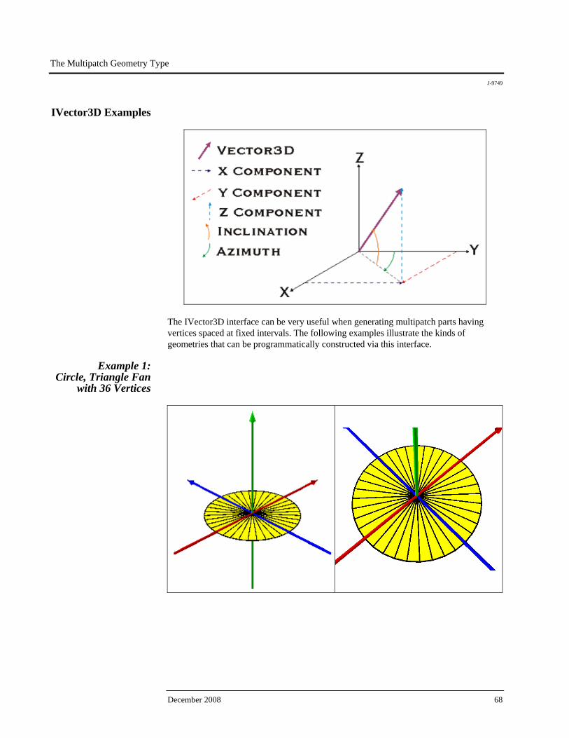
The Multipatch Geometry Type
J-9749
December 2008 68
IVector3D Examples
The IVector3D interface can be very useful when generating multipatch parts having vertices spaced at fixed intervals. The following examples illustrate the kinds of geometries that can be programmatically constructed via this interface.
Example 1: Circle, Triangle Fan
with 36 Vertices
The Multipatch Geometry Type
J-9749
ESRI White Paper 69
public static IGeometry GetExample1() { const double CircleDegrees = 360.0; const int CircleDivisions = 36; const double VectorComponentOffset = 0.0000001; const double CircleRadius = 5.0; const double CircleZ = 0.0; //Vector3D: Circle, TriangleFan With 36 Vertices IGeometryCollection multiPatchGeometryCollection = new MultiPatchClass(); IPointCollection triangleFanPointCollection = new TriangleFanClass(); //Set Circle Origin To (0, 0, CircleZ) IPoint originPoint = GeometryUtilities.ConstructPoint3D(0, 0, CircleZ); //Add Origin Point To Triangle Fan triangleFanPointCollection.AddPoint( originPoint, ref _missing, ref _missing ); //Define Upper Portion Of Axis Around Which Vector Should Be Rotated //To Generate Circle Vertices IVector3D upperAxisVector3D = GeometryUtilities.ConstructVector3D(0, 0, 10); //Define Lower Portion of Axis Around Which Vector Should Be Rotated //To Generate Circle Vertices IVector3D lowerAxisVector3D = GeometryUtilities.ConstructVector3D(0, 0, -10); //Add Slight Offset To X or Y Component Of One Of Axis Vectors //So Cross Product Does Not Return A Zero-Length Vector lowerAxisVector3D.XComponent += VectorComponentOffset; //Obtain Cross Product Of Upper And Lower Axis Vectors To Obtain //Normal Vector To Axis Of Rotation To Generate Circle Vertices IVector3D normalVector3D = upperAxisVector3D.CrossProduct(lowerAxisVector3D) as IVector3D; //Set Normal Vector Magnitude Equal To Radius Of Circle normalVector3D.Magnitude = CircleRadius; //Obtain Angle Of Rotation In Radians As Function Of //Number Of Divisions Within 360 Degree Sweep Of Circle double rotationAngleInRadians = GeometryUtilities.GetRadians(CircleDegrees / CircleDivisions); for (int i = 0; i < CircleDivisions; i++) {
The Multipatch Geometry Type
J-9749
December 2008 70
//Rotate Normal Vector Specified Rotation Angle In Radians //Around Either Upper Or Lower Axis normalVector3D.Rotate( -1 * rotationAngleInRadians, upperAxisVector3D ); //Construct Circle Vertex Whose XY Coordinates Are The Sum Of //Origin XY Coordinates And Normal Vector XY Components IPoint vertexPoint = GeometryUtilities.ConstructPoint3D( originPoint.X + normalVector3D.XComponent, originPoint.Y + normalVector3D.YComponent, CircleZ ); //Add Vertex To TriangleFan triangleFanPointCollection.AddPoint( vertexPoint, ref _missing, ref _missing ); } //Re-Add The Second Point Of The Triangle Fan (First Vertex Added) //To Close The Fan triangleFanPointCollection.AddPoint( triangleFanPointCollection.get_Point(1), ref _missing, ref _missing ); //Add TriangleFan To MultiPatch multiPatchGeometryCollection.AddGeometry( triangleFanPointCollection as IGeometry, ref _missing, ref _missing ); return multiPatchGeometryCollection as IGeometry; }
Note that it is necessary to add a slight offset to either the x or y component of one of the two vectors involved in obtaining a cross-product or normal vector. This is to prevent the cross-product from returning a zero-magnitude vector. Also, note that when we call Rotate(), we multiply our rotation angle by -1. This is because Rotate() follows the mathematical convention of the meaning of a positive angle. A positive angle would cause the vector to rotate in a counterclockwise manner. Because we would like to add our points in a clockwise manner, as discussed earlier, we must multiply our angle of rotation by -1. Finally, it is a good idea to experiment with the number of vertices used when generating these geometries. For a range of 360 degrees, for example, it may not be necessary to use 360 vertices. At a certain distance, 36 vertices may look just as good and result in significantly enhanced rendering performance.
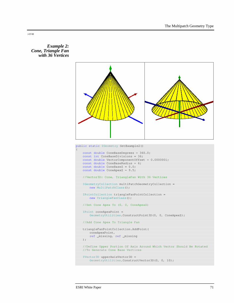
The Multipatch Geometry Type
J-9749
ESRI White Paper 71
Example 2: Cone, Triangle Fan
with 36 Vertices
public static IGeometry GetExample2() { const double ConeBaseDegrees = 360.0; const int ConeBaseDivisions = 36; const double VectorComponentOffset = 0.0000001; const double ConeBaseRadius = 6; const double ConeBaseZ = 0.0; const double ConeApexZ = 9.5; //Vector3D: Cone, TriangleFan With 36 Vertices IGeometryCollection multiPatchGeometryCollection = new MultiPatchClass(); IPointCollection triangleFanPointCollection = new TriangleFanClass(); //Set Cone Apex To (0, 0, ConeApexZ) IPoint coneApexPoint = GeometryUtilities.ConstructPoint3D(0, 0, ConeApexZ); //Add Cone Apex To Triangle Fan triangleFanPointCollection.AddPoint( coneApexPoint, ref _missing, ref _missing ); //Define Upper Portion Of Axis Around Which Vector Should Be Rotated //To Generate Cone Base Vertices IVector3D upperAxisVector3D = GeometryUtilities.ConstructVector3D(0, 0, 10);
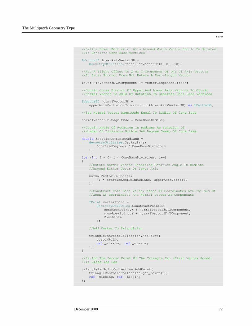
The Multipatch Geometry Type
J-9749
December 2008 72
//Define Lower Portion of Axis Around Which Vector Should Be Rotated //To Generate Cone Base Vertices IVector3D lowerAxisVector3D = GeometryUtilities.ConstructVector3D(0, 0, -10); //Add A Slight Offset To X or Y Component Of One Of Axis Vectors //So Cross Product Does Not Return A Zero-Length Vector lowerAxisVector3D.XComponent += VectorComponentOffset; //Obtain Cross Product Of Upper And Lower Axis Vectors To Obtain //Normal Vector To Axis Of Rotation To Generate Cone Base Vertices IVector3D normalVector3D = upperAxisVector3D.CrossProduct(lowerAxisVector3D) as IVector3D; //Set Normal Vector Magnitude Equal To Radius Of Cone Base normalVector3D.Magnitude = ConeBaseRadius; //Obtain Angle Of Rotation In Radians As Function Of //Number Of Divisions Within 360 Degree Sweep Of Cone Base double rotationAngleInRadians = GeometryUtilities.GetRadians( ConeBaseDegrees / ConeBaseDivisions ); for (int i = 0; i < ConeBaseDivisions; i++) { //Rotate Normal Vector Specified Rotation Angle In Radians //Around Either Upper Or Lower Axis normalVector3D.Rotate( -1 * rotationAngleInRadians, upperAxisVector3D ); //Construct Cone Base Vertex Whose XY Coordinates Are The Sum Of //Apex XY Coordinates And Normal Vector XY Components IPoint vertexPoint = GeometryUtilities.ConstructPoint3D( coneApexPoint.X + normalVector3D.XComponent, coneApexPoint.Y + normalVector3D.YComponent, ConeBaseZ ); //Add Vertex To TriangleFan triangleFanPointCollection.AddPoint( vertexPoint, ref _missing, ref _missing ); } //Re-Add The Second Point Of The Triangle Fan (First Vertex Added) //To Close The Fan triangleFanPointCollection.AddPoint( triangleFanPointCollection.get_Point(1), ref _missing, ref _missing );
The Multipatch Geometry Type
J-9749
ESRI White Paper 73
//Add TriangleFan To MultiPatch multiPatchGeometryCollection.AddGeometry( triangleFanPointCollection as IGeometry, ref _missing, ref _missing ); return multiPatchGeometryCollection as IGeometry; }
This example is just the same as the previous, only that the origin or apex z-value is set to a value that differs from the vertex z-values, resulting in a cone-shaped triangle fan.
Example 3: Cylinder, Triangle
Strip with 36 Vertices
public static IGeometry GetExample3() { const double CylinderBaseDegrees = 360.0; const int CylinderBaseDivisions = 36; const double VectorComponentOffset = 0.0000001; const double CylinderBaseRadius = 3; const double CylinderUpperZ = 8; const double CylinderLowerZ = 0; //Vector3D: Cylinder, TriangleStrip With 36 Vertices IGeometryCollection multiPatchGeometryCollection = new MultiPatchClass(); IPointCollection triangleStripPointCollection = new TriangleStripClass(); //Set Cylinder Base Origin To (0, 0, 0) IPoint originPoint = GeometryUtilities.ConstructPoint3D(0, 0, 0);

The Multipatch Geometry Type
J-9749
December 2008 74
//Define Upper Portion Of Axis Around Which Vector Should Be Rotated //To Generate Cylinder Base Vertices IVector3D upperAxisVector3D = GeometryUtilities.ConstructVector3D(0, 0, 10); //Define Lower Portion of Axis Around Which Vector Should Be Rotated //To Generate Cylinder Base Vertices IVector3D lowerAxisVector3D = GeometryUtilities.ConstructVector3D(0, 0, -10); //Add A Slight Offset To X or Y Component Of One Of Axis Vectors //So Cross Product Does Not Return A Zero-Length Vector lowerAxisVector3D.XComponent += VectorComponentOffset; //Obtain Cross Product Of Upper And Lower Axis Vectors To Obtain //Normal Vector To Axis Of Rotation To Generate Cylinder Base Vertices IVector3D normalVector3D = upperAxisVector3D.CrossProduct(lowerAxisVector3D) as IVector3D; //Set Normal Vector Magnitude Equal To Radius Of Cylinder Base normalVector3D.Magnitude = CylinderBaseRadius; //Obtain Angle Of Rotation In Radians As Function Of //Number Of Divisions Within 360 Degree Sweep Of Cylinder Base double rotationAngleInRadians = GeometryUtilities.GetRadians( CylinderBaseDegrees / CylinderBaseDivisions ); for (int i = 0; i < CylinderBaseDivisions; i++) { //Rotate Normal Vector Specified Rotation Angle In Radians //Around Either Upper Or Lower Axis normalVector3D.Rotate( rotationAngleInRadians, upperAxisVector3D ); //Construct Cylinder Base Vertex Whose XY Coordinates Are The //Sum Of Origin XY Coordinates And Normal Vector XY Components IPoint vertexPoint = GeometryUtilities.ConstructPoint3D( originPoint.X + normalVector3D.XComponent, originPoint.Y + normalVector3D.YComponent, 0 ); //Construct Lower Base Vertex From This Point And //Add To TriangleStrip IPoint lowerVertexPoint = GeometryUtilities.ConstructPoint3D( vertexPoint.X, vertexPoint.Y, CylinderLowerZ ); triangleStripPointCollection.AddPoint( lowerVertexPoint, ref _missing, ref _missing );
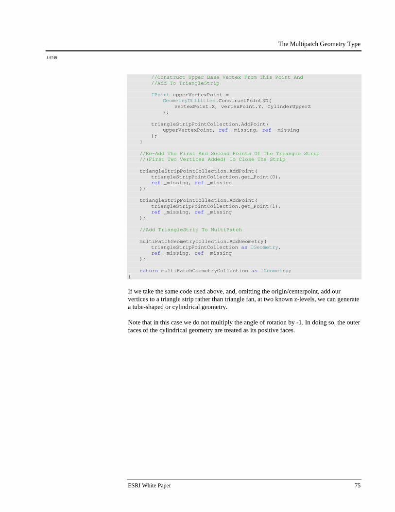
The Multipatch Geometry Type
J-9749
ESRI White Paper 75
//Construct Upper Base Vertex From This Point And //Add To TriangleStrip IPoint upperVertexPoint = GeometryUtilities.ConstructPoint3D( vertexPoint.X, vertexPoint.Y, CylinderUpperZ ); triangleStripPointCollection.AddPoint( upperVertexPoint, ref _missing, ref _missing ); } //Re-Add The First And Second Points Of The Triangle Strip //(First Two Vertices Added) To Close The Strip triangleStripPointCollection.AddPoint( triangleStripPointCollection.get_Point(0), ref _missing, ref _missing ); triangleStripPointCollection.AddPoint( triangleStripPointCollection.get_Point(1), ref _missing, ref _missing ); //Add TriangleStrip To MultiPatch multiPatchGeometryCollection.AddGeometry( triangleStripPointCollection as IGeometry, ref _missing, ref _missing ); return multiPatchGeometryCollection as IGeometry; }
If we take the same code used above, and, omitting the origin/centerpoint, add our vertices to a triangle strip rather than triangle fan, at two known z-levels, we can generate a tube-shaped or cylindrical geometry. Note that in this case we do not multiply the angle of rotation by -1. In doing so, the outer faces of the cylindrical geometry are treated as its positive faces.
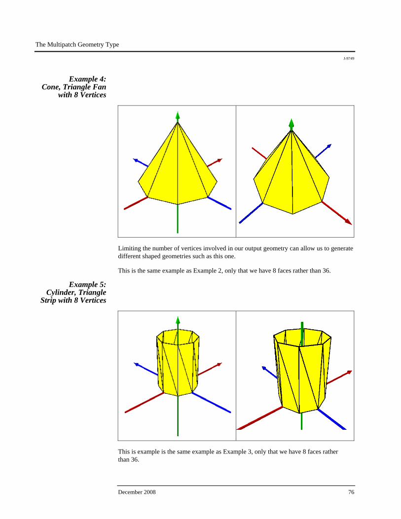
The Multipatch Geometry Type
J-9749
December 2008 76
Example 4: Cone, Triangle Fan
with 8 Vertices
Limiting the number of vertices involved in our output geometry can allow us to generate different shaped geometries such as this one. This is the same example as Example 2, only that we have 8 faces rather than 36.
Example 5: Cylinder, Triangle
Strip with 8 Vertices
This is example is the same example as Example 3, only that we have 8 faces rather than 36.
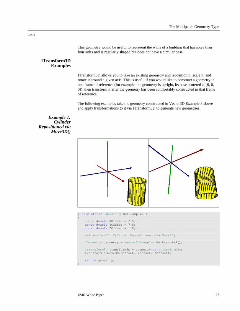
The Multipatch Geometry Type
J-9749
ESRI White Paper 77
This geometry would be useful to represent the walls of a building that has more than four sides and is regularly shaped but does not have a circular base.
ITransform3D Examples
ITransform3D allows you to take an existing geometry and reposition it, scale it, and rotate it around a given axis. This is useful if you would like to construct a geometry in one frame of reference (for example, the geometry is upright, its base centered at [0, 0, 0]), then transform it after the geometry has been comfortably constructed in that frame of reference. The following examples take the geometry constructed in Vector3D Example 3 above and apply transformations to it via ITransform3D to generate new geometries.
Example 1: Cylinder
Repositioned via Move3D()
public static IGeometry GetExample1() { const double XOffset = 7.5; const double YOffset = 7.5; const double ZOffset = -10; //Transform3D: Cylinder Repositioned Via Move3D() IGeometry geometry = Vector3DExamples.GetExample3(); ITransform3D transform3D = geometry as ITransform3D; transform3D.Move3D(XOffset, YOffset, ZOffset); return geometry; }
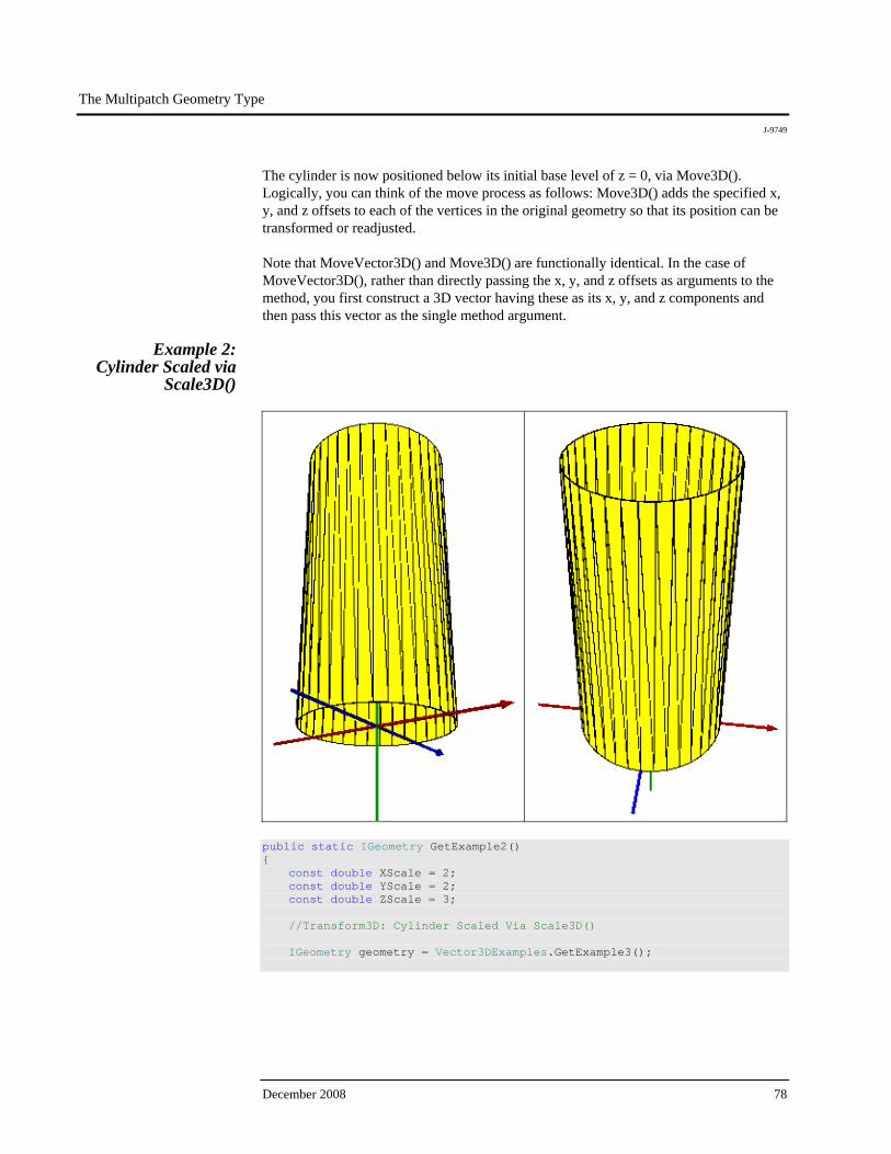
The Multipatch Geometry Type
J-9749
December 2008 78
The cylinder is now positioned below its initial base level of z = 0, via Move3D(). Logically, you can think of the move process as follows: Move3D() adds the specified x, y, and z offsets to each of the vertices in the original geometry so that its position can be transformed or readjusted. Note that MoveVector3D() and Move3D() are functionally identical. In the case of MoveVector3D(), rather than directly passing the x, y, and z offsets as arguments to the method, you first construct a 3D vector having these as its x, y, and z components and then pass this vector as the single method argument.
Example 2: Cylinder Scaled via
Scale3D()
public static IGeometry GetExample2() { const double XScale = 2; const double YScale = 2; const double ZScale = 3; //Transform3D: Cylinder Scaled Via Scale3D() IGeometry geometry = Vector3DExamples.GetExample3();
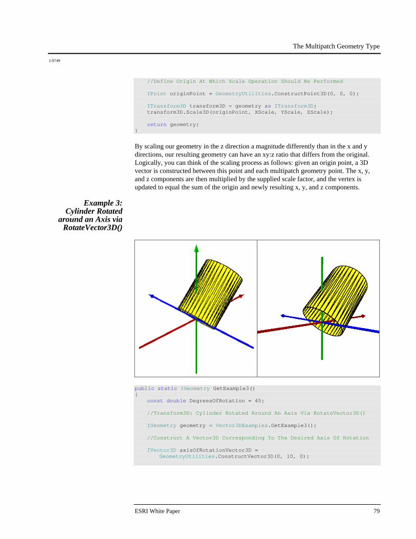
The Multipatch Geometry Type
J-9749
ESRI White Paper 79
//Define Origin At Which Scale Operation Should Be Performed IPoint originPoint = GeometryUtilities.ConstructPoint3D(0, 0, 0); ITransform3D transform3D = geometry as ITransform3D; transform3D.Scale3D(originPoint, XScale, YScale, ZScale); return geometry; }
By scaling our geometry in the z direction a magnitude differently than in the x and y directions, our resulting geometry can have an xy:z ratio that differs from the original. Logically, you can think of the scaling process as follows: given an origin point, a 3D vector is constructed between this point and each multipatch geometry point. The x, y, and z components are then multiplied by the supplied scale factor, and the vertex is updated to equal the sum of the origin and newly resulting x, y, and z components.
Example 3: Cylinder Rotated
around an Axis via RotateVector3D()
public static IGeometry GetExample3() { const double DegreesOfRotation = 45; //Transform3D: Cylinder Rotated Around An Axis Via RotateVector3D() IGeometry geometry = Vector3DExamples.GetExample3(); //Construct A Vector3D Corresponding To The Desired Axis Of Rotation IVector3D axisOfRotationVector3D = GeometryUtilities.ConstructVector3D(0, 10, 0);
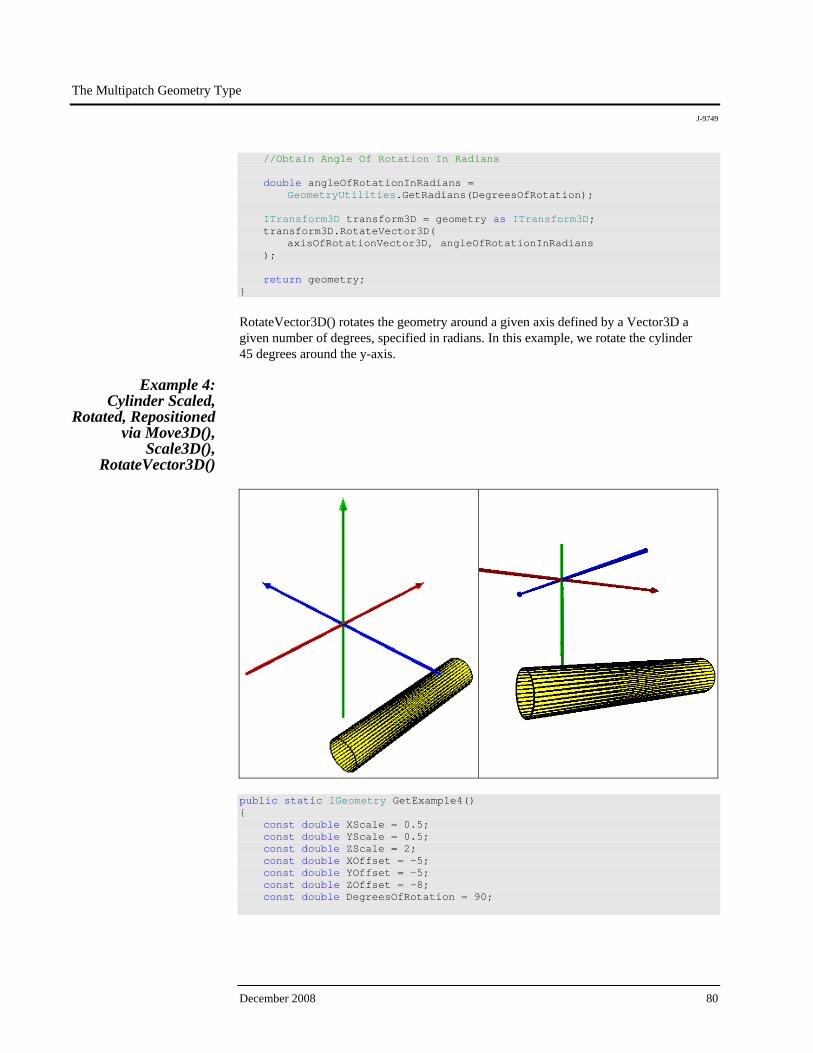
The Multipatch Geometry Type
J-9749
December 2008 80
//Obtain Angle Of Rotation In Radians double angleOfRotationInRadians = GeometryUtilities.GetRadians(DegreesOfRotation); ITransform3D transform3D = geometry as ITransform3D; transform3D.RotateVector3D( axisOfRotationVector3D, angleOfRotationInRadians ); return geometry; }
RotateVector3D() rotates the geometry around a given axis defined by a Vector3D a given number of degrees, specified in radians. In this example, we rotate the cylinder 45 degrees around the y-axis.
Example 4: Cylinder Scaled,
Rotated, Repositioned via Move3D(),
Scale3D(), RotateVector3D()
public static IGeometry GetExample4() { const double XScale = 0.5; const double YScale = 0.5; const double ZScale = 2; const double XOffset = -5; const double YOffset = -5; const double ZOffset = -8; const double DegreesOfRotation = 90;
The Multipatch Geometry Type
J-9749
ESRI White Paper 81
//Transform3D: Cylinder Scaled, Rotated, Repositioned Via //Move3D(), Scale3D(), RotateVector3D() IGeometry geometry = Vector3DExamples.GetExample3(); ITransform3D transform3D = geometry as ITransform3D; //Stretch The Cylinder So It Looks Like A Tube IPoint originPoint = GeometryUtilities.ConstructPoint3D(0, 0, 0); transform3D.Scale3D(originPoint, XScale, YScale, ZScale); //Rotate The Cylinder So It Lies On Its Side IVector3D axisOfRotationVector3D = GeometryUtilities.ConstructVector3D(0, 10, 0); double angleOfRotationInRadians = GeometryUtilities.GetRadians(DegreesOfRotation); transform3D.RotateVector3D( axisOfRotationVector3D, angleOfRotationInRadians ); //Reposition The Cylinder So It Is Located Underground transform3D.Move3D(XOffset, YOffset, ZOffset); return geometry; }
Multiple calls to methods exposed by ITransform3D can be made against a single geometry, allowing it to be moved, scaled, and rotated. In this example, all three methods are called, allowing an upright cylinder whose base is centered at (0, 0, 0) to be transformed into an underground tube or pipe, stretched, and rotated 90 degrees to lie on its side.
IConstruct MultiPatch
Examples
IConstructMultiPatch is an interface designed to allow you to extrude a base 2D or 3D geometry in one of several ways to generate a multipatch representation. The following examples illustrate the differences between and kinds of geometries that can be generated via these methods.
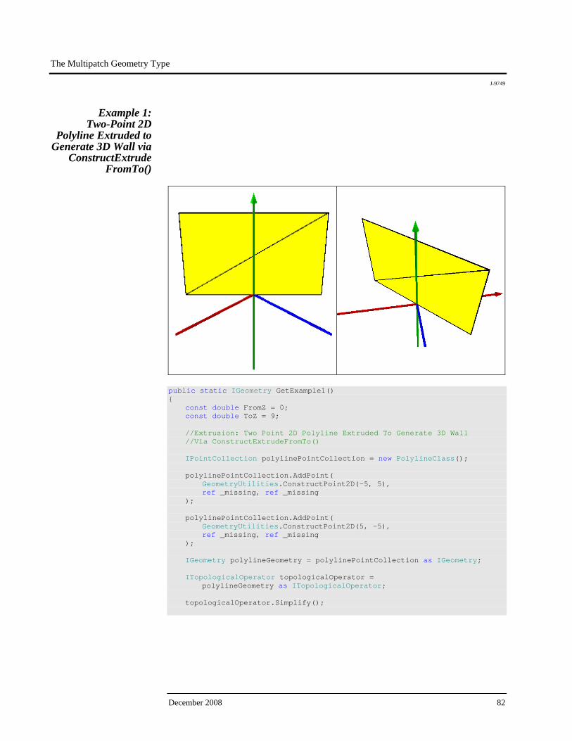
The Multipatch Geometry Type
J-9749
December 2008 82
Example 1: Two-Point 2D
Polyline Extruded to Generate 3D Wall via
ConstructExtrude FromTo()
public static IGeometry GetExample1() { const double FromZ = 0; const double ToZ = 9; //Extrusion: Two Point 2D Polyline Extruded To Generate 3D Wall //Via ConstructExtrudeFromTo() IPointCollection polylinePointCollection = new PolylineClass(); polylinePointCollection.AddPoint( GeometryUtilities.ConstructPoint2D(-5, 5), ref _missing, ref _missing ); polylinePointCollection.AddPoint( GeometryUtilities.ConstructPoint2D(5, -5), ref _missing, ref _missing ); IGeometry polylineGeometry = polylinePointCollection as IGeometry; ITopologicalOperator topologicalOperator = polylineGeometry as ITopologicalOperator; topologicalOperator.Simplify();
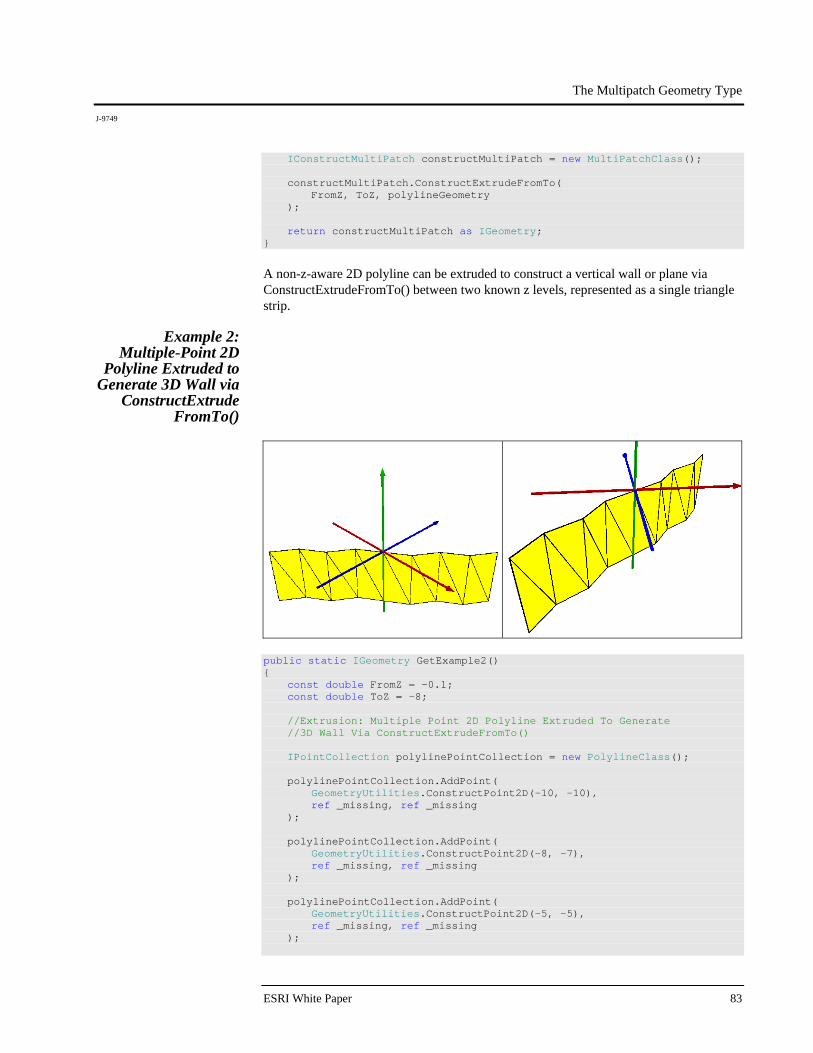
The Multipatch Geometry Type
J-9749
ESRI White Paper 83
IConstructMultiPatch constructMultiPatch = new MultiPatchClass(); constructMultiPatch.ConstructExtrudeFromTo( FromZ, ToZ, polylineGeometry ); return constructMultiPatch as IGeometry; }
A non-z-aware 2D polyline can be extruded to construct a vertical wall or plane via ConstructExtrudeFromTo() between two known z levels, represented as a single triangle strip.
Example 2: Multiple-Point 2D
Polyline Extruded to Generate 3D Wall via
ConstructExtrude FromTo()
public static IGeometry GetExample2() { const double FromZ = -0.1; const double ToZ = -8; //Extrusion: Multiple Point 2D Polyline Extruded To Generate //3D Wall Via ConstructExtrudeFromTo() IPointCollection polylinePointCollection = new PolylineClass(); polylinePointCollection.AddPoint( GeometryUtilities.ConstructPoint2D(-10, -10), ref _missing, ref _missing ); polylinePointCollection.AddPoint( GeometryUtilities.ConstructPoint2D(-8, -7), ref _missing, ref _missing ); polylinePointCollection.AddPoint( GeometryUtilities.ConstructPoint2D(-5, -5), ref _missing, ref _missing );

The Multipatch Geometry Type
J-9749
December 2008 84
polylinePointCollection.AddPoint( GeometryUtilities.ConstructPoint2D(-3, -2), ref _missing, ref _missing ); polylinePointCollection.AddPoint( GeometryUtilities.ConstructPoint2D(0, 0), ref _missing, ref _missing ); polylinePointCollection.AddPoint( GeometryUtilities.ConstructPoint2D(3, 2), ref _missing, ref _missing ); polylinePointCollection.AddPoint( GeometryUtilities.ConstructPoint2D(5, 5), ref _missing, ref _missing ); polylinePointCollection.AddPoint( GeometryUtilities.ConstructPoint2D(8, 7), ref _missing, ref _missing ); polylinePointCollection.AddPoint( GeometryUtilities.ConstructPoint2D(10, 10), ref _missing, ref _missing ); IGeometry polylineGeometry = polylinePointCollection as IGeometry; ITopologicalOperator topologicalOperator = polylineGeometry as ITopologicalOperator; topologicalOperator.Simplify(); IConstructMultiPatch constructMultiPatch = new MultiPatchClass(); constructMultiPatch.ConstructExtrudeFromTo( FromZ, ToZ, polylineGeometry ); return constructMultiPatch as IGeometry; }
This example illustrates the effect of applying the same extrusion to a 2D polyline containing multiple vertices, resulting in a triangle strip with multiple panels.
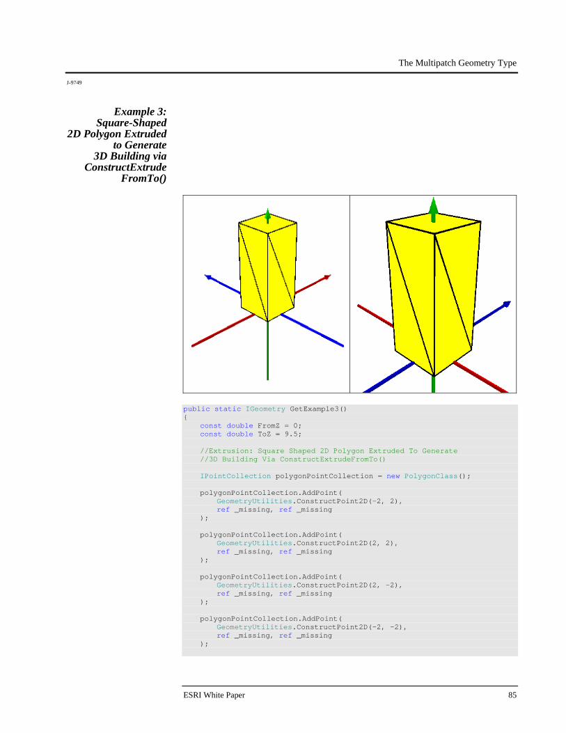
The Multipatch Geometry Type
J-9749
ESRI White Paper 85
Example 3: Square-Shaped
2D Polygon Extruded to Generate
3D Building via ConstructExtrude
FromTo()
public static IGeometry GetExample3() { const double FromZ = 0; const double ToZ = 9.5; //Extrusion: Square Shaped 2D Polygon Extruded To Generate //3D Building Via ConstructExtrudeFromTo() IPointCollection polygonPointCollection = new PolygonClass(); polygonPointCollection.AddPoint( GeometryUtilities.ConstructPoint2D(-2, 2), ref _missing, ref _missing ); polygonPointCollection.AddPoint( GeometryUtilities.ConstructPoint2D(2, 2), ref _missing, ref _missing ); polygonPointCollection.AddPoint( GeometryUtilities.ConstructPoint2D(2, -2), ref _missing, ref _missing ); polygonPointCollection.AddPoint( GeometryUtilities.ConstructPoint2D(-2, -2), ref _missing, ref _missing );
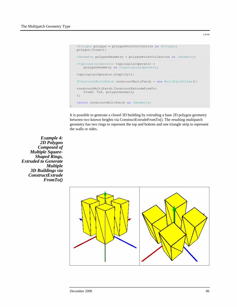
The Multipatch Geometry Type
J-9749
December 2008 86
IPolygon polygon = polygonPointCollection as IPolygon; polygon.Close(); IGeometry polygonGeometry = polygonPointCollection as IGeometry; ITopologicalOperator topologicalOperator = polygonGeometry as ITopologicalOperator; topologicalOperator.Simplify(); IConstructMultiPatch constructMultiPatch = new MultiPatchClass(); constructMultiPatch.ConstructExtrudeFromTo( FromZ, ToZ, polygonGeometry ); return constructMultiPatch as IGeometry; }
It is possible to generate a closed 3D building by extruding a base 2D polygon geometry between two known heights via ConstructExtrudeFromTo(). The resulting multipatch geometry has two rings to represent the top and bottom and one triangle strip to represent the walls or sides.
Example 4: 2D Polygon
Composed of Multiple Square-
Shaped Rings, Extruded to Generate
Multiple 3D Buildings via
ConstructExtrude FromTo()
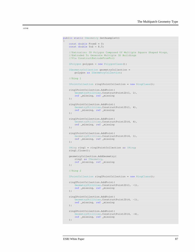
The Multipatch Geometry Type
J-9749
ESRI White Paper 87
public static IGeometry GetExample4() { const double FromZ = 0; const double ToZ = 8.5; //Extrusion: 2D Polygon Composed Of Multiple Square Shaped Rings, //Extruded To Generate Multiple 3D Buildings //Via ConstructExtrudeFromTo() IPolygon polygon = new PolygonClass(); IGeometryCollection geometryCollection = polygon as IGeometryCollection; //Ring 1 IPointCollection ring1PointCollection = new RingClass(); ring1PointCollection.AddPoint( GeometryUtilities.ConstructPoint2D(1, 1), ref _missing, ref _missing ); ring1PointCollection.AddPoint( GeometryUtilities.ConstructPoint2D(1, 4), ref _missing, ref _missing ); ring1PointCollection.AddPoint( GeometryUtilities.ConstructPoint2D(4, 4), ref _missing, ref _missing ); ring1PointCollection.AddPoint( GeometryUtilities.ConstructPoint2D(4, 1), ref _missing, ref _missing ); IRing ring1 = ring1PointCollection as IRing; ring1.Close(); geometryCollection.AddGeometry( ring1 as IGeometry, ref _missing, ref _missing ); //Ring 2 IPointCollection ring2PointCollection = new RingClass(); ring2PointCollection.AddPoint( GeometryUtilities.ConstructPoint2D(1, -1), ref _missing, ref _missing ); ring2PointCollection.AddPoint( GeometryUtilities.ConstructPoint2D(4, -1), ref _missing, ref _missing ); ring2PointCollection.AddPoint( GeometryUtilities.ConstructPoint2D(4, -4), ref _missing, ref _missing );
The Multipatch Geometry Type
J-9749
December 2008 88
ring2PointCollection.AddPoint( GeometryUtilities.ConstructPoint2D(1, -4), ref _missing, ref _missing ); IRing ring2 = ring2PointCollection as IRing; ring2.Close(); geometryCollection.AddGeometry( ring2 as IGeometry, ref _missing, ref _missing ); //Ring 3 IPointCollection ring3PointCollection = new RingClass(); ring3PointCollection.AddPoint( GeometryUtilities.ConstructPoint2D(-1, 1), ref _missing, ref _missing ); ring3PointCollection.AddPoint( GeometryUtilities.ConstructPoint2D(-4, 1), ref _missing, ref _missing ); ring3PointCollection.AddPoint( GeometryUtilities.ConstructPoint2D(-4, 4), ref _missing, ref _missing ); ring3PointCollection.AddPoint( GeometryUtilities.ConstructPoint2D(-1, 4), ref _missing, ref _missing ); IRing ring3 = ring3PointCollection as IRing; ring3.Close(); geometryCollection.AddGeometry( ring3 as IGeometry, ref _missing, ref _missing ); //Ring 4 IPointCollection ring4PointCollection = new RingClass(); ring4PointCollection.AddPoint( GeometryUtilities.ConstructPoint2D(-1, -1), ref _missing, ref _missing ); ring4PointCollection.AddPoint( GeometryUtilities.ConstructPoint2D(-1, -4), ref _missing, ref _missing ); ring4PointCollection.AddPoint( GeometryUtilities.ConstructPoint2D(-4, -4), ref _missing, ref _missing );
The Multipatch Geometry Type
J-9749
ESRI White Paper 89
ring4PointCollection.AddPoint( GeometryUtilities.ConstructPoint2D(-4, -1), ref _missing, ref _missing ); IRing ring4 = ring4PointCollection as IRing; ring4.Close(); geometryCollection.AddGeometry( ring4 as IGeometry, ref _missing, ref _missing ); IGeometry polygonGeometry = polygon as IGeometry; ITopologicalOperator topologicalOperator = polygonGeometry as ITopologicalOperator; topologicalOperator.Simplify(); IConstructMultiPatch constructMultiPatch = new MultiPatchClass(); constructMultiPatch.ConstructExtrudeFromTo( FromZ, ToZ, polygonGeometry ); return constructMultiPatch as IGeometry; }
When a 2D polygon consisting of multiple rings is extruded, each of the rings it contains is extruded. The result, in this example, is a single multipatch consisting of four 3D buildings, each one composed of two rings and one triangle strip, as described in the previous example.
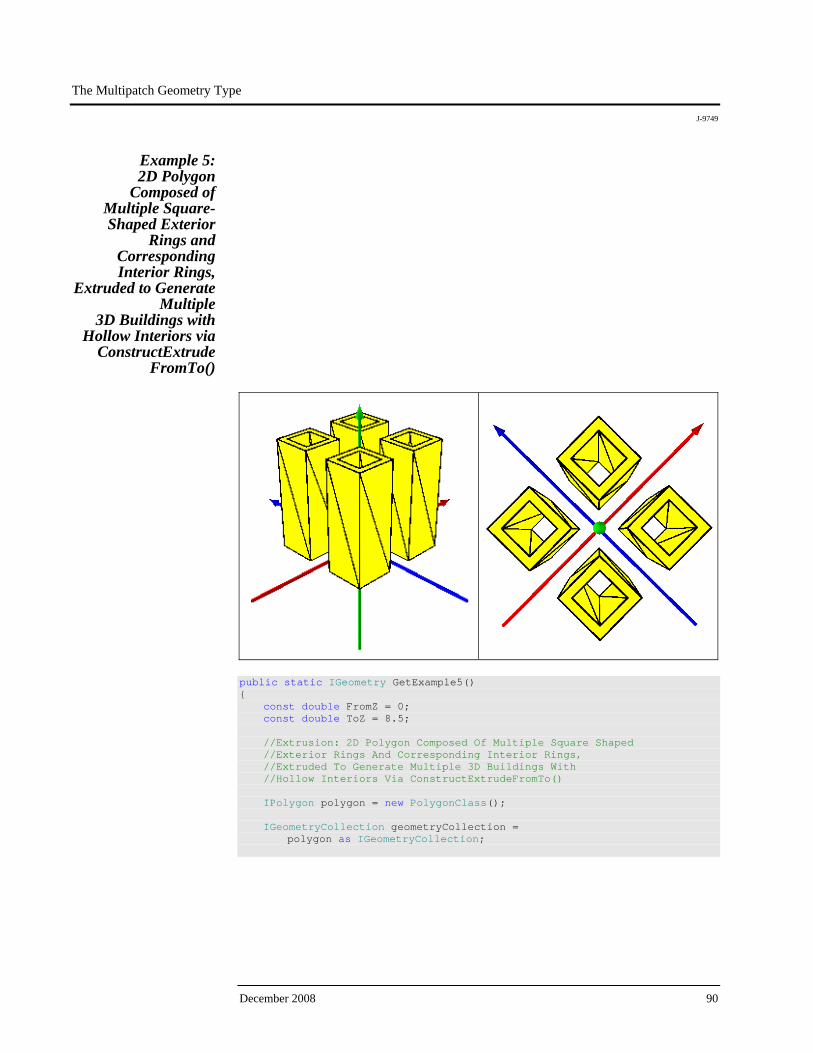
The Multipatch Geometry Type
J-9749
December 2008 90
Example 5: 2D Polygon
Composed of Multiple Square-Shaped Exterior
Rings and Corresponding Interior Rings,
Extruded to Generate Multiple
3D Buildings with Hollow Interiors via
ConstructExtrude FromTo()
public static IGeometry GetExample5() { const double FromZ = 0; const double ToZ = 8.5; //Extrusion: 2D Polygon Composed Of Multiple Square Shaped //Exterior Rings And Corresponding Interior Rings, //Extruded To Generate Multiple 3D Buildings With //Hollow Interiors Via ConstructExtrudeFromTo() IPolygon polygon = new PolygonClass(); IGeometryCollection geometryCollection = polygon as IGeometryCollection;
The Multipatch Geometry Type
J-9749
ESRI White Paper 91
//Exterior Ring 1 IPointCollection exteriorRing1PointCollection = new RingClass(); exteriorRing1PointCollection.AddPoint( GeometryUtilities.ConstructPoint2D(1, 1), ref _missing, ref _missing ); exteriorRing1PointCollection.AddPoint( GeometryUtilities.ConstructPoint2D(1, 4), ref _missing, ref _missing ); exteriorRing1PointCollection.AddPoint( GeometryUtilities.ConstructPoint2D(4, 4), ref _missing, ref _missing ); exteriorRing1PointCollection.AddPoint( GeometryUtilities.ConstructPoint2D(4, 1), ref _missing, ref _missing ); IRing exteriorRing1 = exteriorRing1PointCollection as IRing; exteriorRing1.Close(); geometryCollection.AddGeometry( exteriorRing1 as IGeometry, ref _missing, ref _missing ); //Interior Ring 1 IPointCollection interiorRing1PointCollection = new RingClass(); interiorRing1PointCollection.AddPoint( GeometryUtilities.ConstructPoint2D(1.5, 1.5), ref _missing, ref _missing ); interiorRing1PointCollection.AddPoint( GeometryUtilities.ConstructPoint2D(1.5, 3.5), ref _missing, ref _missing ); interiorRing1PointCollection.AddPoint( GeometryUtilities.ConstructPoint2D(3.5, 3.5), ref _missing, ref _missing ); interiorRing1PointCollection.AddPoint( GeometryUtilities.ConstructPoint2D(3.5, 1.5), ref _missing, ref _missing ); IRing interiorRing1 = interiorRing1PointCollection as IRing; interiorRing1.Close(); geometryCollection.AddGeometry( interiorRing1 as IGeometry, ref _missing, ref _missing );

The Multipatch Geometry Type
J-9749
December 2008 92
//Exterior Ring 2 IPointCollection exteriorRing2PointCollection = new RingClass(); exteriorRing2PointCollection.AddPoint( GeometryUtilities.ConstructPoint2D(1, -1), ref _missing, ref _missing ); exteriorRing2PointCollection.AddPoint( GeometryUtilities.ConstructPoint2D(4, -1), ref _missing, ref _missing ); exteriorRing2PointCollection.AddPoint( GeometryUtilities.ConstructPoint2D(4, -4), ref _missing, ref _missing ); exteriorRing2PointCollection.AddPoint( GeometryUtilities.ConstructPoint2D(1, -4), ref _missing, ref _missing ); IRing exteriorRing2 = exteriorRing2PointCollection as IRing; exteriorRing2.Close(); geometryCollection.AddGeometry( exteriorRing2 as IGeometry, ref _missing, ref _missing ); //Interior Ring 2 IPointCollection interiorRing2PointCollection = new RingClass(); interiorRing2PointCollection.AddPoint( GeometryUtilities.ConstructPoint2D(1.5, -1.5), ref _missing, ref _missing ); interiorRing2PointCollection.AddPoint( GeometryUtilities.ConstructPoint2D(3.5, -1.5), ref _missing, ref _missing ); interiorRing2PointCollection.AddPoint( GeometryUtilities.ConstructPoint2D(3.5, -3.5), ref _missing, ref _missing ); interiorRing2PointCollection.AddPoint( GeometryUtilities.ConstructPoint2D(1.5, -3.5), ref _missing, ref _missing ); IRing interiorRing2 = interiorRing2PointCollection as IRing; interiorRing2.Close(); geometryCollection.AddGeometry( interiorRing2 as IGeometry, ref _missing, ref _missing );

The Multipatch Geometry Type
J-9749
ESRI White Paper 93
//Exterior Ring 3 IPointCollection exteriorRing3PointCollection = new RingClass(); exteriorRing3PointCollection.AddPoint( GeometryUtilities.ConstructPoint2D(-1, 1), ref _missing, ref _missing ); exteriorRing3PointCollection.AddPoint( GeometryUtilities.ConstructPoint2D(-4, 1), ref _missing, ref _missing ); exteriorRing3PointCollection.AddPoint( GeometryUtilities.ConstructPoint2D(-4, 4), ref _missing, ref _missing ); exteriorRing3PointCollection.AddPoint( GeometryUtilities.ConstructPoint2D(-1, 4), ref _missing, ref _missing ); IRing exteriorRing3 = exteriorRing3PointCollection as IRing; exteriorRing3.Close(); geometryCollection.AddGeometry( exteriorRing3 as IGeometry, ref _missing, ref _missing ); //Interior Ring 3 IPointCollection interiorRing3PointCollection = new RingClass(); interiorRing3PointCollection.AddPoint( GeometryUtilities.ConstructPoint2D(-1.5, 1.5), ref _missing, ref _missing ); interiorRing3PointCollection.AddPoint( GeometryUtilities.ConstructPoint2D(-3.5, 1.5), ref _missing, ref _missing ); interiorRing3PointCollection.AddPoint( GeometryUtilities.ConstructPoint2D(-3.5, 3.5), ref _missing, ref _missing ); interiorRing3PointCollection.AddPoint( GeometryUtilities.ConstructPoint2D(-1.5, 3.5), ref _missing, ref _missing ); IRing interiorRing3 = interiorRing3PointCollection as IRing; interiorRing3.Close(); geometryCollection.AddGeometry( interiorRing3 as IGeometry, ref _missing, ref _missing );
The Multipatch Geometry Type
J-9749
December 2008 94
//Exterior Ring 4 IPointCollection exteriorRing4PointCollection = new RingClass(); exteriorRing4PointCollection.AddPoint( GeometryUtilities.ConstructPoint2D(-1, -1), ref _missing, ref _missing ); exteriorRing4PointCollection.AddPoint( GeometryUtilities.ConstructPoint2D(-1, -4), ref _missing, ref _missing ); exteriorRing4PointCollection.AddPoint( GeometryUtilities.ConstructPoint2D(-4, -4), ref _missing, ref _missing ); exteriorRing4PointCollection.AddPoint( GeometryUtilities.ConstructPoint2D(-4, -1), ref _missing, ref _missing ); IRing exteriorRing4 = exteriorRing4PointCollection as IRing; exteriorRing4.Close(); geometryCollection.AddGeometry( exteriorRing4 as IGeometry, ref _missing, ref _missing ); //Interior Ring 5 IPointCollection interiorRing4PointCollection = new RingClass(); interiorRing4PointCollection.AddPoint( GeometryUtilities.ConstructPoint2D(-1.5, -1.5), ref _missing, ref _missing ); interiorRing4PointCollection.AddPoint( GeometryUtilities.ConstructPoint2D(-1.5, -3.5), ref _missing, ref _missing ); interiorRing4PointCollection.AddPoint( GeometryUtilities.ConstructPoint2D(-3.5, -3.5), ref _missing, ref _missing ); interiorRing4PointCollection.AddPoint( GeometryUtilities.ConstructPoint2D(-3.5, -1.5), ref _missing, ref _missing ); IRing interiorRing4 = interiorRing4PointCollection as IRing; interiorRing4.Close(); geometryCollection.AddGeometry( interiorRing4 as IGeometry, ref _missing, ref _missing );
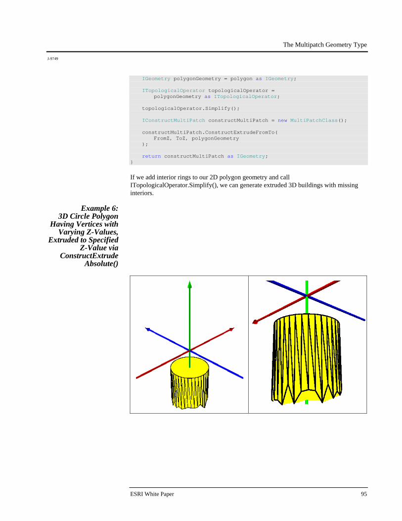
The Multipatch Geometry Type
J-9749
ESRI White Paper 95
IGeometry polygonGeometry = polygon as IGeometry; ITopologicalOperator topologicalOperator = polygonGeometry as ITopologicalOperator; topologicalOperator.Simplify(); IConstructMultiPatch constructMultiPatch = new MultiPatchClass(); constructMultiPatch.ConstructExtrudeFromTo( FromZ, ToZ, polygonGeometry ); return constructMultiPatch as IGeometry; }
If we add interior rings to our 2D polygon geometry and call ITopologicalOperator.Simplify(), we can generate extruded 3D buildings with missing interiors.
Example 6: 3D Circle Polygon
Having Vertices with Varying Z-Values,
Extruded to Specified Z-Value via
ConstructExtrude Absolute()
The Multipatch Geometry Type
J-9749
December 2008 96
public static IGeometry GetExample6() { const double CircleDegrees = 360.0; const int CircleDivisions = 36; const double VectorComponentOffset = 0.0000001; const double CircleRadius = 3.0; const double BaseZ = -10; const double ToZ = -3; //Extrusion: 3D Circle Polygon Having Vertices With Varying //Z Values, Extruded To Specified Z Value //Via ConstructExtrudeAbsolute() IGeometryCollection multiPatchGeometryCollection = new MultiPatchClass(); IPointCollection polygonPointCollection = new PolygonClass(); IPoint originPoint = GeometryUtilities.ConstructPoint3D(0, 0, 0); IVector3D upperAxisVector3D = GeometryUtilities.ConstructVector3D(0, 0, 10); IVector3D lowerAxisVector3D = GeometryUtilities.ConstructVector3D(0, 0, -10); lowerAxisVector3D.XComponent += VectorComponentOffset; IVector3D normalVector3D = upperAxisVector3D.CrossProduct(lowerAxisVector3D) as IVector3D; normalVector3D.Magnitude = CircleRadius; double rotationAngleInRadians = GeometryUtilities.GetRadians(CircleDegrees / CircleDivisions); Random random = new Random(); for (int i = 0; i < CircleDivisions; i++) { normalVector3D.Rotate( -1 * rotationAngleInRadians, upperAxisVector3D ); IPoint vertexPoint = GeometryUtilities.ConstructPoint3D( originPoint.X + normalVector3D.XComponent, originPoint.Y + normalVector3D.YComponent, BaseZ + 2 * Math.Sin(random.NextDouble()) ); polygonPointCollection.AddPoint( vertexPoint, ref _missing, ref _missing ); } IPolygon polygon = polygonPointCollection as IPolygon; polygon.Close(); IGeometry polygonGeometry = polygon as IGeometry; GeometryUtilities.MakeZAware(polygonGeometry);
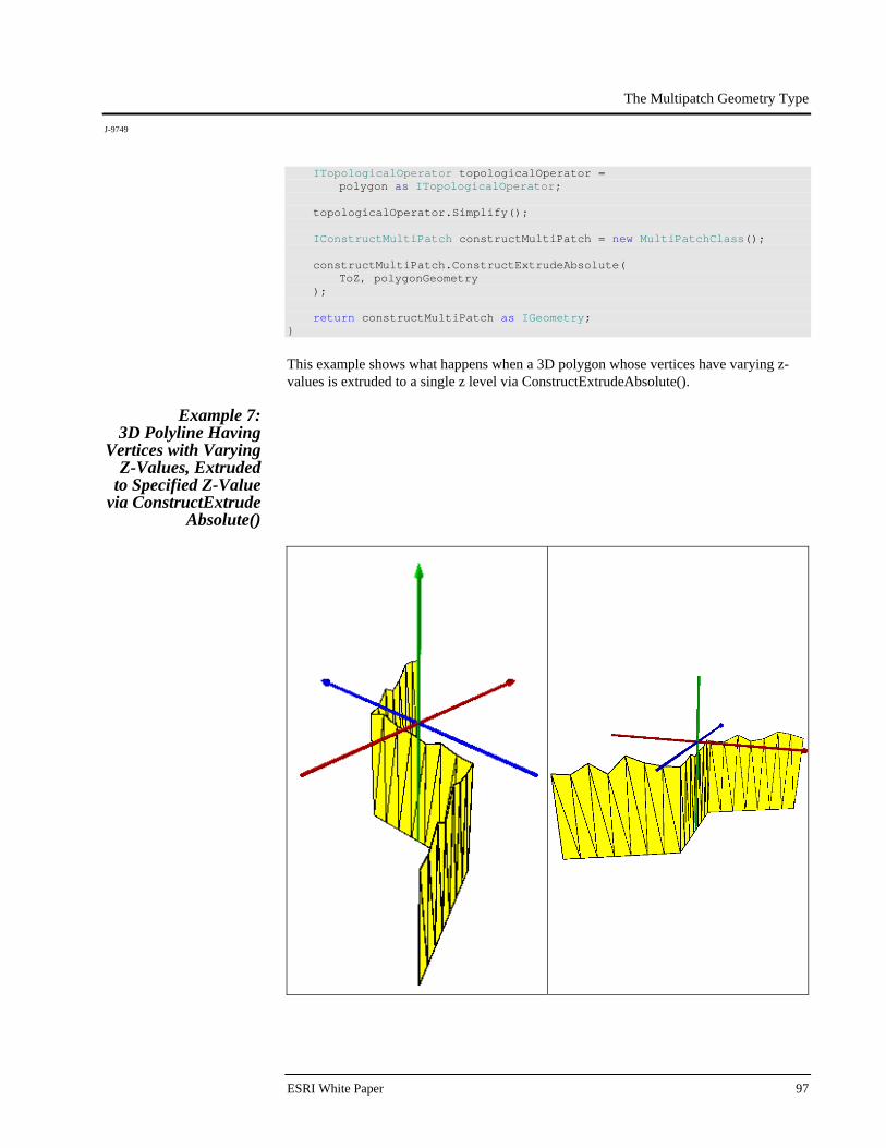
The Multipatch Geometry Type
J-9749
ESRI White Paper 97
ITopologicalOperator topologicalOperator = polygon as ITopologicalOperator; topologicalOperator.Simplify(); IConstructMultiPatch constructMultiPatch = new MultiPatchClass(); constructMultiPatch.ConstructExtrudeAbsolute( ToZ, polygonGeometry ); return constructMultiPatch as IGeometry; }
This example shows what happens when a 3D polygon whose vertices have varying z-values is extruded to a single z level via ConstructExtrudeAbsolute().
Example 7: 3D Polyline Having
Vertices with Varying Z-Values, Extruded
to Specified Z-Value via ConstructExtrude
Absolute()
The Multipatch Geometry Type
J-9749
December 2008 98
public static IGeometry GetExample7() { const int DensificationDivisions = 20; const double MaxDeviation = 0.1; const double BaseZ = 0; const double ToZ = -10; //Extrusion: 3D Polyline Having Vertices With Varying Z Values, //Extruded To Specified Z Value Via //ConstructExtrudeAbsolute() IPointCollection polylinePointCollection = new PolylineClass(); polylinePointCollection.AddPoint( GeometryUtilities.ConstructPoint2D(-10, -10), ref _missing, ref _missing ); polylinePointCollection.AddPoint( GeometryUtilities.ConstructPoint2D(0, -5), ref _missing, ref _missing ); polylinePointCollection.AddPoint( GeometryUtilities.ConstructPoint2D(0, 5), ref _missing, ref _missing ); polylinePointCollection.AddPoint( GeometryUtilities.ConstructPoint2D(10, 10), ref _missing, ref _missing ); IPolyline polyline = polylinePointCollection as IPolyline; polyline.Densify( polyline.Length / DensificationDivisions, MaxDeviation ); IGeometry polylineGeometry = polyline as IGeometry; GeometryUtilities.MakeZAware(polylineGeometry); Random random = new Random(); for (int i = 0; i < polylinePointCollection.PointCount; i++) { IPoint polylinePoint = polylinePointCollection.get_Point(i); polylinePointCollection.UpdatePoint( i, GeometryUtilities.ConstructPoint3D( polylinePoint.X, polylinePoint.Y, BaseZ - 2 * Math.Sin(random.NextDouble()) ) ); }
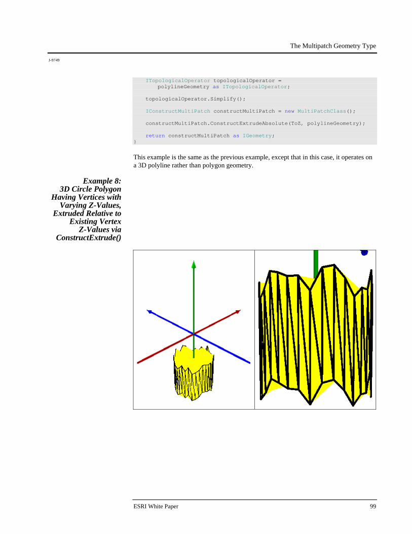
The Multipatch Geometry Type
J-9749
ESRI White Paper 99
ITopologicalOperator topologicalOperator = polylineGeometry as ITopologicalOperator; topologicalOperator.Simplify(); IConstructMultiPatch constructMultiPatch = new MultiPatchClass(); constructMultiPatch.ConstructExtrudeAbsolute(ToZ, polylineGeometry); return constructMultiPatch as IGeometry; }
This example is the same as the previous example, except that in this case, it operates on a 3D polyline rather than polygon geometry.
Example 8: 3D Circle Polygon
Having Vertices with Varying Z-Values,
Extruded Relative to Existing Vertex
Z-Values via ConstructExtrude()
The Multipatch Geometry Type
J-9749
December 2008 100
public static IGeometry GetExample8() { const double CircleDegrees = 360.0; const int CircleDivisions = 36; const double VectorComponentOffset = 0.0000001; const double CircleRadius = 3.0; const double BaseZ = -10; const double OffsetZ = 5; //Extrusion: 3D Circle Polygon Having Vertices With Varying Z Values, //Extruded Relative To Existing Vertex Z Values Via //ConstructExtrude() IGeometryCollection multiPatchGeometryCollection = new MultiPatchClass(); IPointCollection polygonPointCollection = new PolygonClass(); IPoint originPoint = GeometryUtilities.ConstructPoint3D(0, 0, 0); IVector3D upperAxisVector3D = GeometryUtilities.ConstructVector3D(0, 0, 10); IVector3D lowerAxisVector3D = GeometryUtilities.ConstructVector3D(0, 0, -10); lowerAxisVector3D.XComponent += VectorComponentOffset; IVector3D normalVector3D = upperAxisVector3D.CrossProduct(lowerAxisVector3D) as IVector3D; normalVector3D.Magnitude = CircleRadius; double rotationAngleInRadians = GeometryUtilities.GetRadians(CircleDegrees / CircleDivisions); Random random = new Random(); for (int i = 0; i < CircleDivisions; i++) { normalVector3D.Rotate( -1 * rotationAngleInRadians, upperAxisVector3D ); IPoint vertexPoint = GeometryUtilities.ConstructPoint3D( originPoint.X + normalVector3D.XComponent, originPoint.Y + normalVector3D.YComponent, BaseZ + 2 * Math.Sin(random.NextDouble()) ); polygonPointCollection.AddPoint( vertexPoint, ref _missing, ref _missing ); } IPolygon polygon = polygonPointCollection as IPolygon; polygon.Close(); IGeometry polygonGeometry = polygon as IGeometry; GeometryUtilities.MakeZAware(polygonGeometry);
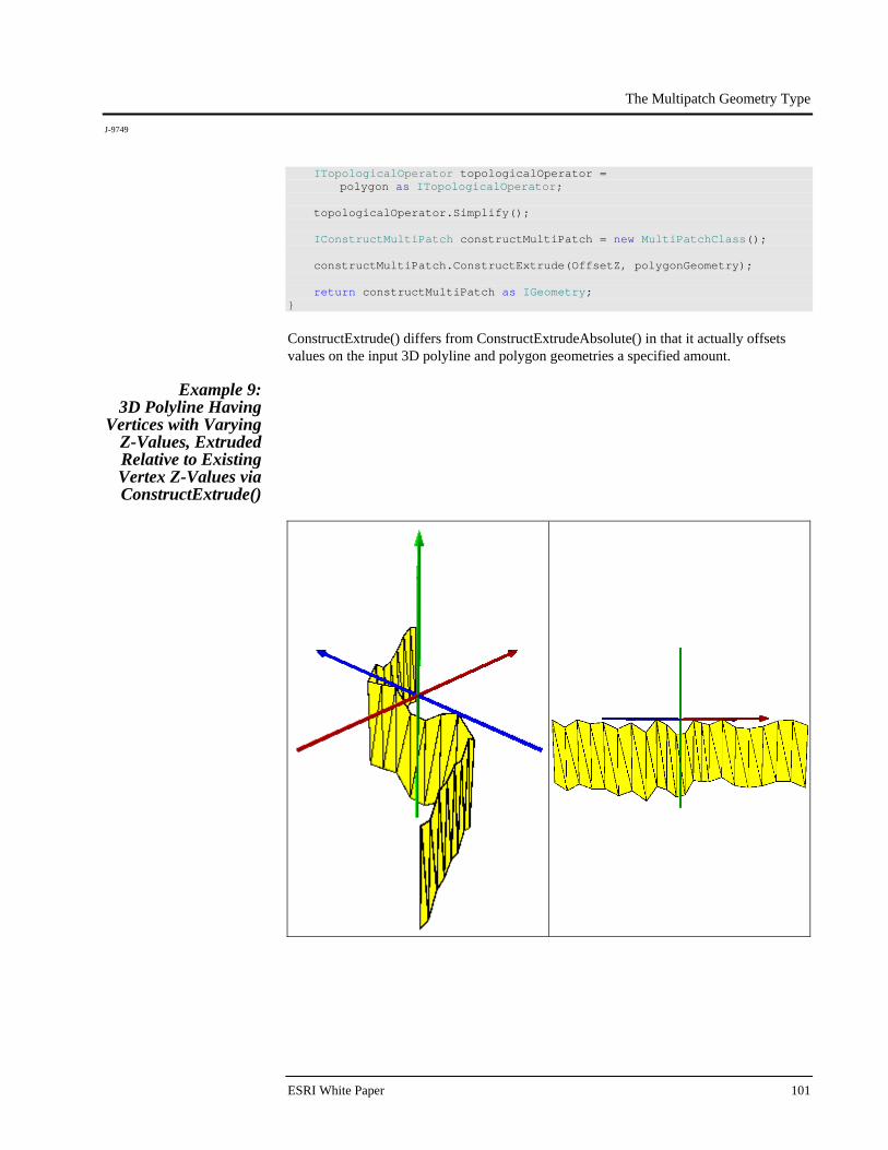
The Multipatch Geometry Type
J-9749
ESRI White Paper 101
ITopologicalOperator topologicalOperator = polygon as ITopologicalOperator; topologicalOperator.Simplify(); IConstructMultiPatch constructMultiPatch = new MultiPatchClass(); constructMultiPatch.ConstructExtrude(OffsetZ, polygonGeometry); return constructMultiPatch as IGeometry; }
ConstructExtrude() differs from ConstructExtrudeAbsolute() in that it actually offsets values on the input 3D polyline and polygon geometries a specified amount.
Example 9: 3D Polyline Having
Vertices with Varying Z-Values, Extruded Relative to Existing Vertex Z-Values via ConstructExtrude()
The Multipatch Geometry Type
J-9749
December 2008 102
public static IGeometry GetExample9() { const int DensificationDivisions = 20; const double MaxDeviation = 0.1; const double BaseZ = 0; const double OffsetZ = -7; //Extrusion: 3D Polyline Having Vertices With Varying Z Values, //Extruded Relative To Existing Vertex Z Values //Via ConstructExtrude() IPointCollection polylinePointCollection = new PolylineClass(); polylinePointCollection.AddPoint( GeometryUtilities.ConstructPoint2D(-10, -10), ref _missing, ref _missing ); polylinePointCollection.AddPoint( GeometryUtilities.ConstructPoint2D(0, -5), ref _missing, ref _missing ); polylinePointCollection.AddPoint( GeometryUtilities.ConstructPoint2D(0, 5), ref _missing, ref _missing ); polylinePointCollection.AddPoint( GeometryUtilities.ConstructPoint2D(10, 10), ref _missing, ref _missing ); IPolyline polyline = polylinePointCollection as IPolyline; polyline.Densify( polyline.Length / DensificationDivisions, MaxDeviation ); IGeometry polylineGeometry = polyline as IGeometry; GeometryUtilities.MakeZAware(polylineGeometry); Random random = new Random(); for (int i = 0; i < polylinePointCollection.PointCount; i++) { IPoint polylinePoint = polylinePointCollection.get_Point(i); polylinePointCollection.UpdatePoint( i, GeometryUtilities.ConstructPoint3D( polylinePoint.X, polylinePoint.Y, BaseZ - 2 * Math.Sin(random.NextDouble()) ) ); }
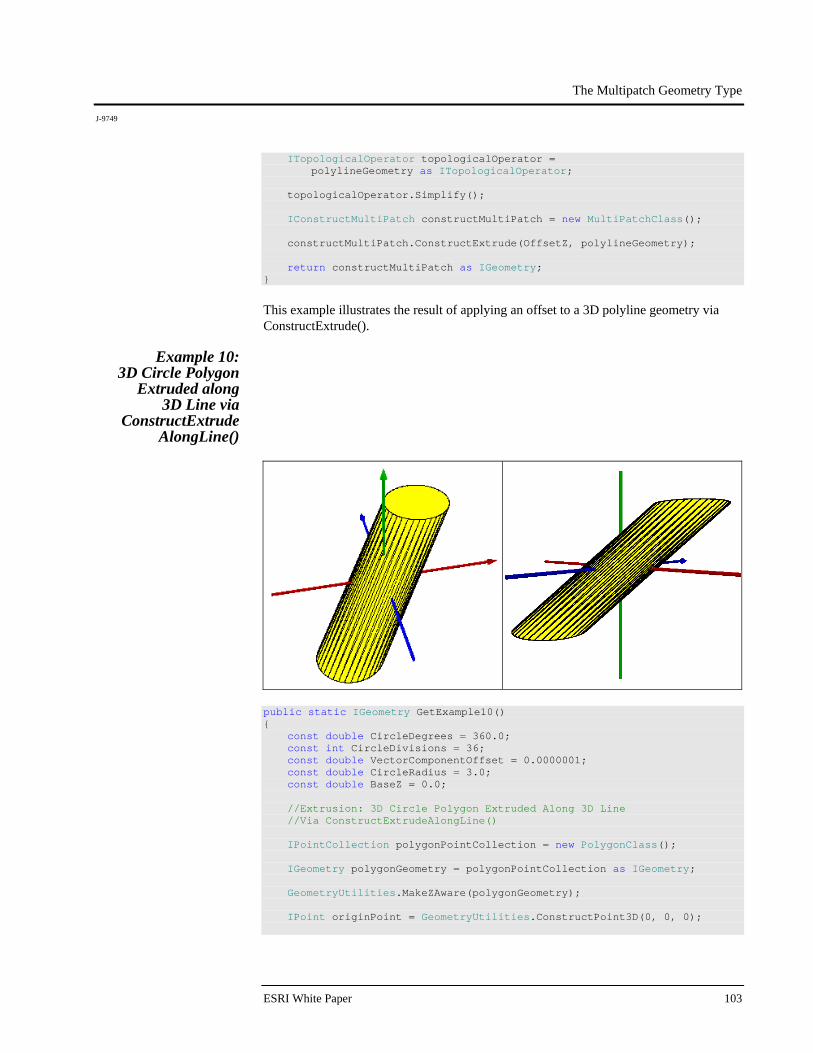
The Multipatch Geometry Type
J-9749
ESRI White Paper 103
ITopologicalOperator topologicalOperator = polylineGeometry as ITopologicalOperator; topologicalOperator.Simplify(); IConstructMultiPatch constructMultiPatch = new MultiPatchClass(); constructMultiPatch.ConstructExtrude(OffsetZ, polylineGeometry); return constructMultiPatch as IGeometry; }
This example illustrates the result of applying an offset to a 3D polyline geometry via ConstructExtrude().
Example 10: 3D Circle Polygon
Extruded along 3D Line via
ConstructExtrude AlongLine()
public static IGeometry GetExample10() { const double CircleDegrees = 360.0; const int CircleDivisions = 36; const double VectorComponentOffset = 0.0000001; const double CircleRadius = 3.0; const double BaseZ = 0.0; //Extrusion: 3D Circle Polygon Extruded Along 3D Line //Via ConstructExtrudeAlongLine() IPointCollection polygonPointCollection = new PolygonClass(); IGeometry polygonGeometry = polygonPointCollection as IGeometry; GeometryUtilities.MakeZAware(polygonGeometry); IPoint originPoint = GeometryUtilities.ConstructPoint3D(0, 0, 0);
The Multipatch Geometry Type
J-9749
December 2008 104
IVector3D upperAxisVector3D = GeometryUtilities.ConstructVector3D(0, 0, 10); IVector3D lowerAxisVector3D = GeometryUtilities.ConstructVector3D(0, 0, -10); lowerAxisVector3D.XComponent += VectorComponentOffset; IVector3D normalVector3D = upperAxisVector3D.CrossProduct(lowerAxisVector3D) as IVector3D; normalVector3D.Magnitude = CircleRadius; double rotationAngleInRadians = GeometryUtilities.GetRadians(CircleDegrees / CircleDivisions); for (int i = 0; i < CircleDivisions; i++) { normalVector3D.Rotate( -1 * rotationAngleInRadians, upperAxisVector3D ); IPoint vertexPoint = GeometryUtilities.ConstructPoint3D( originPoint.X + normalVector3D.XComponent, originPoint.Y + normalVector3D.YComponent, BaseZ ); polygonPointCollection.AddPoint( vertexPoint, ref _missing, ref _missing ); } polygonPointCollection.AddPoint( polygonPointCollection.get_Point(0), ref _missing, ref _missing ); ITopologicalOperator topologicalOperator = polygonGeometry as ITopologicalOperator; topologicalOperator.Simplify(); //Define Line To Extrude Along ILine extrusionLine = new LineClass(); extrusionLine.FromPoint = GeometryUtilities.ConstructPoint3D(-4, -4, -5); extrusionLine.ToPoint = GeometryUtilities.ConstructPoint3D(4, 4, 5); //Perform Extrusion IConstructMultiPatch constructMultiPatch = new MultiPatchClass(); constructMultiPatch.ConstructExtrudeAlongLine( extrusionLine, polygonGeometry );
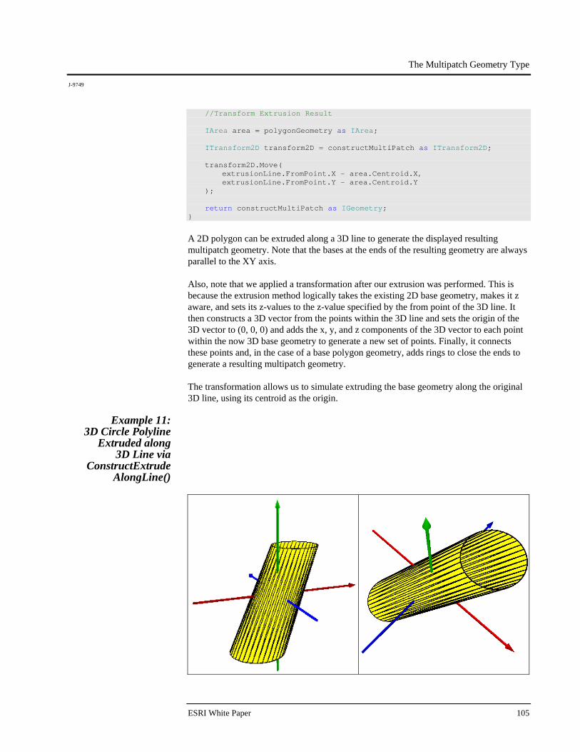
The Multipatch Geometry Type
J-9749
ESRI White Paper 105
//Transform Extrusion Result IArea area = polygonGeometry as IArea; ITransform2D transform2D = constructMultiPatch as ITransform2D; transform2D.Move( extrusionLine.FromPoint.X - area.Centroid.X, extrusionLine.FromPoint.Y - area.Centroid.Y ); return constructMultiPatch as IGeometry; }
A 2D polygon can be extruded along a 3D line to generate the displayed resulting multipatch geometry. Note that the bases at the ends of the resulting geometry are always parallel to the XY axis. Also, note that we applied a transformation after our extrusion was performed. This is because the extrusion method logically takes the existing 2D base geometry, makes it z aware, and sets its z-values to the z-value specified by the from point of the 3D line. It then constructs a 3D vector from the points within the 3D line and sets the origin of the 3D vector to (0, 0, 0) and adds the x, y, and z components of the 3D vector to each point within the now 3D base geometry to generate a new set of points. Finally, it connects these points and, in the case of a base polygon geometry, adds rings to close the ends to generate a resulting multipatch geometry. The transformation allows us to simulate extruding the base geometry along the original 3D line, using its centroid as the origin.
Example 11: 3D Circle Polyline
Extruded along 3D Line via
ConstructExtrude AlongLine()
The Multipatch Geometry Type
J-9749
December 2008 106
public static IGeometry GetExample11() { const double CircleDegrees = 360.0; const int CircleDivisions = 36; const double VectorComponentOffset = 0.0000001; const double CircleRadius = 3.0; const double BaseZ = 0.0; //Extrusion: 3D Circle Polyline Extruded Along 3D Line //Via ConstructExtrudeAlongLine() IPointCollection polylinePointCollection = new PolylineClass(); IGeometry polylineGeometry = polylinePointCollection as IGeometry; GeometryUtilities.MakeZAware(polylineGeometry); IPoint originPoint = GeometryUtilities.ConstructPoint3D(0, 0, 0); IVector3D upperAxisVector3D = GeometryUtilities.ConstructVector3D(0, 0, 10); IVector3D lowerAxisVector3D = GeometryUtilities.ConstructVector3D(0, 0, -10); lowerAxisVector3D.XComponent += VectorComponentOffset; IVector3D normalVector3D = upperAxisVector3D.CrossProduct(lowerAxisVector3D) as IVector3D; normalVector3D.Magnitude = CircleRadius; double rotationAngleInRadians = GeometryUtilities.GetRadians(CircleDegrees / CircleDivisions); for (int i = 0; i < CircleDivisions; i++) { normalVector3D.Rotate( -1 * rotationAngleInRadians, upperAxisVector3D ); IPoint vertexPoint = GeometryUtilities.ConstructPoint3D( originPoint.X + normalVector3D.XComponent, originPoint.Y + normalVector3D.YComponent, BaseZ ); polylinePointCollection.AddPoint( vertexPoint, ref _missing, ref _missing ); } polylinePointCollection.AddPoint( polylinePointCollection.get_Point(0), ref _missing, ref _missing ); ITopologicalOperator topologicalOperator = polylineGeometry as ITopologicalOperator; topologicalOperator.Simplify();

The Multipatch Geometry Type
J-9749
ESRI White Paper 107
//Define Line To Extrude Along ILine extrusionLine = new LineClass(); extrusionLine.FromPoint = GeometryUtilities.ConstructPoint3D(-4, -4, -5); extrusionLine.ToPoint = GeometryUtilities.ConstructPoint3D(4, 4, 5); //Perform Extrusion IConstructMultiPatch constructMultiPatch = new MultiPatchClass(); constructMultiPatch.ConstructExtrudeAlongLine( extrusionLine, polylineGeometry ); //Transform Extrusion Result IPoint centroid = GeometryUtilities.ConstructPoint2D( 0.5 * (polylineGeometry.Envelope.XMax + polylineGeometry.Envelope.XMin), 0.5 * (polylineGeometry.Envelope.YMax + polylineGeometry.Envelope.YMin) ); ITransform2D transform2D = constructMultiPatch as ITransform2D; transform2D.Move( extrusionLine.FromPoint.X - centroid.X, extrusionLine.FromPoint.Y - centroid.Y ); return constructMultiPatch as IGeometry; }
By substituting a 3D polyline for a 3D polygon, we can generate a similar resulting multipatch geometry whose ends are left open. Because a polyline does not have a centroid, we simulate a centroid by constructing a point defined by the average of its envelope's XY extents.
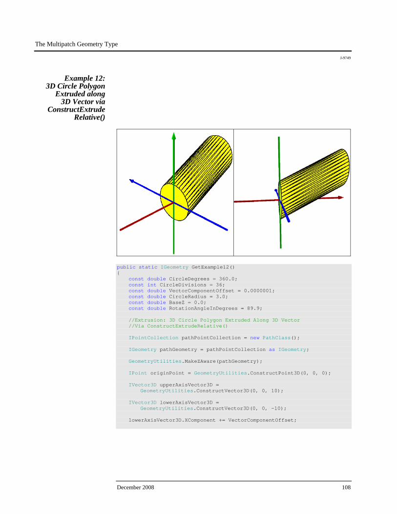
The Multipatch Geometry Type
J-9749
December 2008 108
Example 12: 3D Circle Polygon
Extruded along 3D Vector via
ConstructExtrude Relative()
public static IGeometry GetExample12() { const double CircleDegrees = 360.0; const int CircleDivisions = 36; const double VectorComponentOffset = 0.0000001; const double CircleRadius = 3.0; const double BaseZ = 0.0; const double RotationAngleInDegrees = 89.9; //Extrusion: 3D Circle Polygon Extruded Along 3D Vector //Via ConstructExtrudeRelative() IPointCollection pathPointCollection = new PathClass(); IGeometry pathGeometry = pathPointCollection as IGeometry; GeometryUtilities.MakeZAware(pathGeometry); IPoint originPoint = GeometryUtilities.ConstructPoint3D(0, 0, 0); IVector3D upperAxisVector3D = GeometryUtilities.ConstructVector3D(0, 0, 10); IVector3D lowerAxisVector3D = GeometryUtilities.ConstructVector3D(0, 0, -10); lowerAxisVector3D.XComponent += VectorComponentOffset;
The Multipatch Geometry Type
J-9749
ESRI White Paper 109
IVector3D normalVector3D = upperAxisVector3D.CrossProduct(lowerAxisVector3D) as IVector3D; normalVector3D.Magnitude = CircleRadius; double rotationAngleInRadians = GeometryUtilities.GetRadians(CircleDegrees / CircleDivisions); for (int i = 0; i < CircleDivisions; i++) { normalVector3D.Rotate( -1 * rotationAngleInRadians, upperAxisVector3D ); IPoint vertexPoint = GeometryUtilities.ConstructPoint3D( originPoint.X + normalVector3D.XComponent, originPoint.Y + normalVector3D.YComponent, BaseZ ); pathPointCollection.AddPoint( vertexPoint, ref _missing, ref _missing ); } pathPointCollection.AddPoint( pathPointCollection.get_Point(0), ref _missing, ref _missing ); //Rotate Geometry IVector3D rotationAxisVector3D = GeometryUtilities.ConstructVector3D(0, 10, 0); ITransform3D transform3D = pathGeometry as ITransform3D; transform3D.RotateVector3D( rotationAxisVector3D, GeometryUtilities.GetRadians(RotationAngleInDegrees) ); //Construct Polygon From Path Vertices IGeometry polygonGeometry = new PolygonClass(); GeometryUtilities.MakeZAware(polygonGeometry); IPointCollection polygonPointCollection = polygonGeometry as IPointCollection; for (int i = 0; i < pathPointCollection.PointCount; i++) { polygonPointCollection.AddPoint( pathPointCollection.get_Point(i), ref _missing, ref _missing ); } ITopologicalOperator topologicalOperator = polygonGeometry as ITopologicalOperator; topologicalOperator.Simplify();
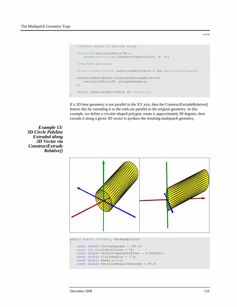
The Multipatch Geometry Type
J-9749
December 2008 110
//Define Vector To Extrude Along IVector3D extrusionVector3D = GeometryUtilities.ConstructVector3D(10, 0, 5); //Perform Extrusion IConstructMultiPatch constructMultiPatch = new MultiPatchClass(); constructMultiPatch.ConstructExtrudeRelative( extrusionVector3D, polygonGeometry ); return constructMultiPatch as IGeometry; }
If a 3D base geometry is not parallel to the XY axis, then the ConstructExtrudeRelative() honors this by extruding it so the ends are parallel to the original geometry. In this example, we define a circular-shaped polygon, rotate it approximately 90 degrees, then extrude it along a given 3D vector to produce the resulting multipatch geometry.
Example 13: 3D Circle Polyline
Extruded along 3D Vector via
ConstructExtrude Relative()
public static IGeometry GetExample13() { const double CircleDegrees = 360.0; const int CircleDivisions = 36; const double VectorComponentOffset = 0.0000001; const double CircleRadius = 3.0; const double BaseZ = 0.0; const double RotationAngleInDegrees = 89.9;
The Multipatch Geometry Type
J-9749
ESRI White Paper 111
//Extrusion: 3D Circle Polyline Extruded Along 3D Vector //Via ConstructExtrudeRelative() IPointCollection pathPointCollection = new PathClass(); IGeometry pathGeometry = pathPointCollection as IGeometry; GeometryUtilities.MakeZAware(pathGeometry); IPoint originPoint = GeometryUtilities.ConstructPoint3D(0, 0, 0); IVector3D upperAxisVector3D = GeometryUtilities.ConstructVector3D(0, 0, 10); IVector3D lowerAxisVector3D = GeometryUtilities.ConstructVector3D(0, 0, -10); lowerAxisVector3D.XComponent += VectorComponentOffset; IVector3D normalVector3D = upperAxisVector3D.CrossProduct(lowerAxisVector3D) as IVector3D; normalVector3D.Magnitude = CircleRadius; double rotationAngleInRadians = GeometryUtilities.GetRadians(CircleDegrees / CircleDivisions); for (int i = 0; i < CircleDivisions; i++) { normalVector3D.Rotate( -1 * rotationAngleInRadians, upperAxisVector3D ); IPoint vertexPoint = GeometryUtilities.ConstructPoint3D( originPoint.X + normalVector3D.XComponent, originPoint.Y + normalVector3D.YComponent, BaseZ ); pathPointCollection.AddPoint( vertexPoint, ref _missing, ref _missing ); } pathPointCollection.AddPoint( pathPointCollection.get_Point(0), ref _missing, ref _missing ); //Rotate Geometry IVector3D rotationAxisVector3D = GeometryUtilities.ConstructVector3D(0, 10, 0); ITransform3D transform3D = pathGeometry as ITransform3D; transform3D.RotateVector3D( rotationAxisVector3D, GeometryUtilities.GetRadians(RotationAngleInDegrees) );
The Multipatch Geometry Type
J-9749
December 2008 112
//Construct Polyline From Path Vertices IGeometry polylineGeometry = new PolylineClass(); GeometryUtilities.MakeZAware(polylineGeometry); IPointCollection polylinePointCollection = polylineGeometry as IPointCollection; for (int i = 0; i < pathPointCollection.PointCount; i++) { polylinePointCollection.AddPoint( pathPointCollection.get_Point(i), ref _missing, ref _missing ); } ITopologicalOperator topologicalOperator = polylineGeometry as ITopologicalOperator; topologicalOperator.Simplify(); //Define Vector To Extrude Along IVector3D extrusionVector3D = GeometryUtilities.ConstructVector3D(10, 0, 5); //Perform Extrusion IConstructMultiPatch constructMultiPatch = new MultiPatchClass(); constructMultiPatch.ConstructExtrudeRelative( extrusionVector3D, polylineGeometry ); return constructMultiPatch as IGeometry; }
This example resembles the previous one, but the ends are left open, as the base geometry is a polyline rather than polygon.
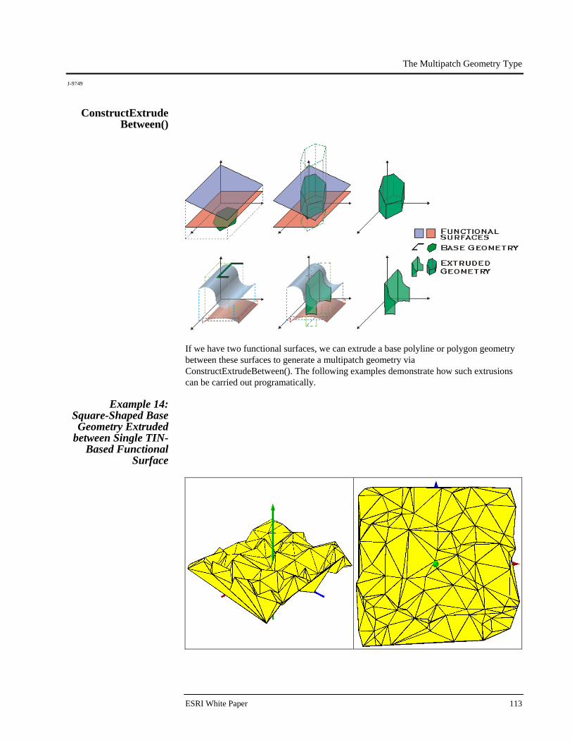
The Multipatch Geometry Type
J-9749
ESRI White Paper 113
ConstructExtrude Between()
If we have two functional surfaces, we can extrude a base polyline or polygon geometry between these surfaces to generate a multipatch geometry via ConstructExtrudeBetween(). The following examples demonstrate how such extrusions can be carried out programatically.
Example 14: Square-Shaped Base Geometry Extruded
between Single TIN-Based Functional
Surface
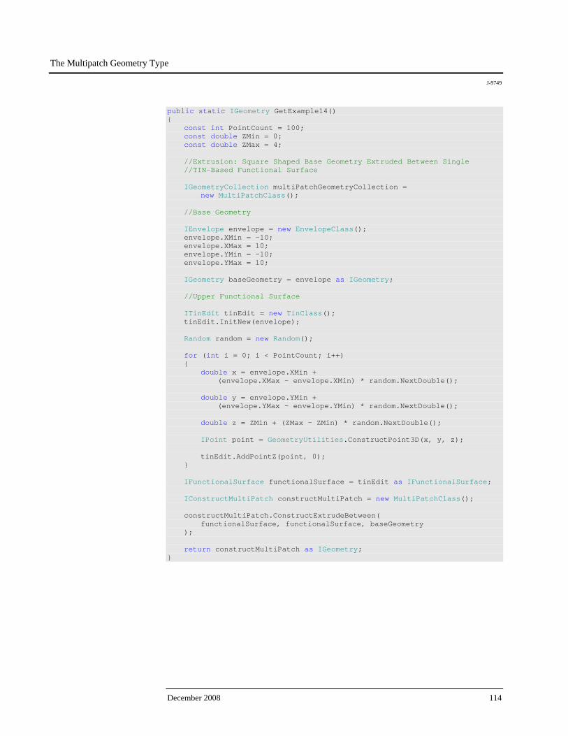
The Multipatch Geometry Type
J-9749
December 2008 114
public static IGeometry GetExample14() { const int PointCount = 100; const double ZMin = 0; const double ZMax = 4; //Extrusion: Square Shaped Base Geometry Extruded Between Single //TIN-Based Functional Surface IGeometryCollection multiPatchGeometryCollection = new MultiPatchClass(); //Base Geometry IEnvelope envelope = new EnvelopeClass(); envelope.XMin = -10; envelope.XMax = 10; envelope.YMin = -10; envelope.YMax = 10; IGeometry baseGeometry = envelope as IGeometry; //Upper Functional Surface ITinEdit tinEdit = new TinClass(); tinEdit.InitNew(envelope); Random random = new Random(); for (int i = 0; i < PointCount; i++) { double x = envelope.XMin + (envelope.XMax - envelope.XMin) * random.NextDouble(); double y = envelope.YMin + (envelope.YMax - envelope.YMin) * random.NextDouble(); double z = ZMin + (ZMax - ZMin) * random.NextDouble(); IPoint point = GeometryUtilities.ConstructPoint3D(x, y, z); tinEdit.AddPointZ(point, 0); } IFunctionalSurface functionalSurface = tinEdit as IFunctionalSurface; IConstructMultiPatch constructMultiPatch = new MultiPatchClass(); constructMultiPatch.ConstructExtrudeBetween( functionalSurface, functionalSurface, baseGeometry ); return constructMultiPatch as IGeometry; }
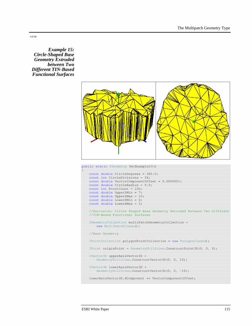
The Multipatch Geometry Type
J-9749
ESRI White Paper 115
Example 15: Circle-Shaped Base Geometry Extruded
between Two Different TIN-Based Functional Surfaces
public static IGeometry GetExample15() { const double CircleDegrees = 360.0; const int CircleDivisions = 36; const double VectorComponentOffset = 0.0000001; const double CircleRadius = 9.5; const int PointCount = 100; const double UpperZMin = 7; const double UpperZMax = 10; const double LowerZMin = 0; const double LowerZMax = 3; //Extrusion: Circle Shaped Base Geometry Extruded Between Two Different //TIN-Based Functional Surfaces IGeometryCollection multiPatchGeometryCollection = new MultiPatchClass(); //Base Geometry IPointCollection polygonPointCollection = new PolygonClass(); IPoint originPoint = GeometryUtilities.ConstructPoint3D(0, 0, 0); IVector3D upperAxisVector3D = GeometryUtilities.ConstructVector3D(0, 0, 10); IVector3D lowerAxisVector3D = GeometryUtilities.ConstructVector3D(0, 0, -10); lowerAxisVector3D.XComponent += VectorComponentOffset;
The Multipatch Geometry Type
J-9749
December 2008 116
IVector3D normalVector3D = upperAxisVector3D.CrossProduct(lowerAxisVector3D) as IVector3D; normalVector3D.Magnitude = CircleRadius; double rotationAngleInRadians = GeometryUtilities.GetRadians(CircleDegrees / CircleDivisions); for (int i = 0; i < CircleDivisions; i++) { normalVector3D.Rotate( -1 * rotationAngleInRadians, upperAxisVector3D ); IPoint vertexPoint = GeometryUtilities.ConstructPoint2D( originPoint.X + normalVector3D.XComponent, originPoint.Y + normalVector3D.YComponent ); polygonPointCollection.AddPoint( vertexPoint, ref _missing, ref _missing ); } IPolygon polygon = polygonPointCollection as IPolygon; polygon.Close(); IGeometry baseGeometry = polygon as IGeometry; ITopologicalOperator topologicalOperator = polygon as ITopologicalOperator; topologicalOperator.Simplify(); //Functional Surfaces IEnvelope envelope = new EnvelopeClass(); envelope.XMin = -10; envelope.XMax = 10; envelope.YMin = -10; envelope.YMax = 10; Random random = new Random(); //Upper Functional Surface ITinEdit upperTinEdit = new TinClass(); upperTinEdit.InitNew(envelope); for (int i = 0; i < PointCount; i++) { double x = envelope.XMin + (envelope.XMax - envelope.XMin) * random.NextDouble(); double y = envelope.YMin + (envelope.YMax - envelope.YMin) * random.NextDouble(); double z = UpperZMin + (UpperZMax - UpperZMin) * random.NextDouble(); IPoint point = GeometryUtilities.ConstructPoint3D(x, y, z); upperTinEdit.AddPointZ(point, 0); }

The Multipatch Geometry Type
J-9749
ESRI White Paper 117
IFunctionalSurface upperFunctionalSurface = upperTinEdit as IFunctionalSurface; //Lower Functional Surface ITinEdit lowerTinEdit = new TinClass(); lowerTinEdit.InitNew(envelope); for (int i = 0; i < PointCount; i++) { double x = envelope.XMin + (envelope.XMax - envelope.XMin) * random.NextDouble(); double y = envelope.YMin + (envelope.YMax - envelope.YMin) * random.NextDouble(); double z = LowerZMin + (LowerZMax - LowerZMin) * random.NextDouble(); IPoint point = GeometryUtilities.ConstructPoint3D(x, y, z); lowerTinEdit.AddPointZ(point, 0); } IFunctionalSurface lowerFunctionalSurface = lowerTinEdit as IFunctionalSurface; IConstructMultiPatch constructMultiPatch = new MultiPatchClass(); constructMultiPatch.ConstructExtrudeBetween( upperFunctionalSurface, lowerFunctionalSurface, baseGeometry ); return constructMultiPatch as IGeometry; }
Composite Examples
The above examples have focused primarily on the kinds of multipatch geometries that can be generated from a single part or patch. But a multipatch by definition (multi + patch) can contain multiple patches of varying types. The follow examples illustrate the kinds of geometries that can be generated through the combination of various patch types.
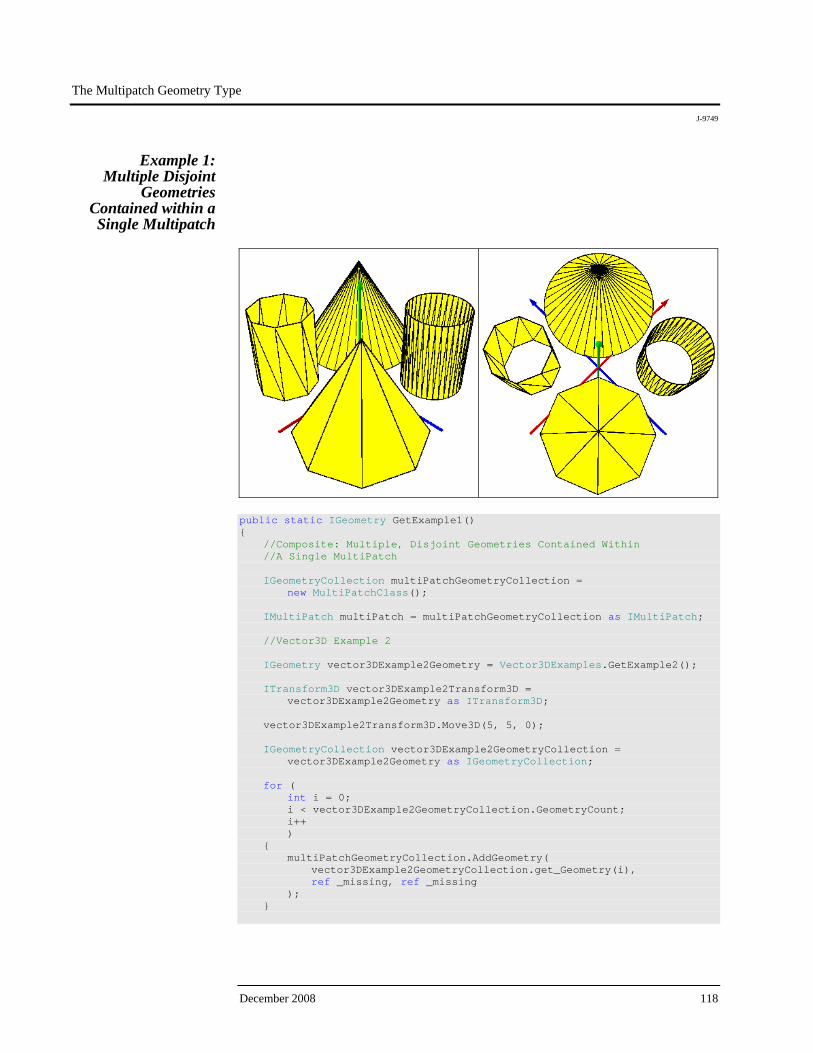
The Multipatch Geometry Type
J-9749
December 2008 118
Example 1: Multiple Disjoint
Geometries Contained within a Single Multipatch
public static IGeometry GetExample1() { //Composite: Multiple, Disjoint Geometries Contained Within //A Single MultiPatch IGeometryCollection multiPatchGeometryCollection = new MultiPatchClass(); IMultiPatch multiPatch = multiPatchGeometryCollection as IMultiPatch; //Vector3D Example 2 IGeometry vector3DExample2Geometry = Vector3DExamples.GetExample2(); ITransform3D vector3DExample2Transform3D = vector3DExample2Geometry as ITransform3D; vector3DExample2Transform3D.Move3D(5, 5, 0); IGeometryCollection vector3DExample2GeometryCollection = vector3DExample2Geometry as IGeometryCollection; for ( int i = 0; i < vector3DExample2GeometryCollection.GeometryCount; i++ ) { multiPatchGeometryCollection.AddGeometry( vector3DExample2GeometryCollection.get_Geometry(i), ref _missing, ref _missing ); }
The Multipatch Geometry Type
J-9749
ESRI White Paper 119
//Vector3D Example 3 IGeometry vector3DExample3Geometry = Vector3DExamples.GetExample3(); ITransform3D vector3DExample3Transform3D = vector3DExample3Geometry as ITransform3D; vector3DExample3Transform3D.Move3D(5, -5, 0); IGeometryCollection vector3DExample3GeometryCollection = vector3DExample3Geometry as IGeometryCollection; for ( int i = 0; i < vector3DExample3GeometryCollection.GeometryCount; i++ ) { multiPatchGeometryCollection.AddGeometry( vector3DExample3GeometryCollection.get_Geometry(i), ref _missing, ref _missing ); } //Vector3D Example 4 IGeometry vector3DExample4Geometry = Vector3DExamples.GetExample4(); ITransform3D vector3DExample4Transform3D = vector3DExample4Geometry as ITransform3D; vector3DExample4Transform3D.Move3D(-5, -5, 0); IGeometryCollection vector3DExample4GeometryCollection = vector3DExample4Geometry as IGeometryCollection; for ( int i = 0; i < vector3DExample4GeometryCollection.GeometryCount; i++ ) { multiPatchGeometryCollection.AddGeometry( vector3DExample4GeometryCollection.get_Geometry(i), ref _missing, ref _missing ); } //Vector3D Example 5 IGeometry vector3DExample5Geometry = Vector3DExamples.GetExample5(); ITransform3D vector3DExample5Transform3D = vector3DExample5Geometry as ITransform3D; vector3DExample5Transform3D.Move3D(-5, 5, 0);

The Multipatch Geometry Type
J-9749
December 2008 120
IGeometryCollection vector3DExample5GeometryCollection = vector3DExample5Geometry as IGeometryCollection; for ( int i = 0; i < vector3DExample5GeometryCollection.GeometryCount; i++ ) { multiPatchGeometryCollection.AddGeometry( vector3DExample5GeometryCollection.get_Geometry(i), ref _missing, ref _missing ); } return multiPatchGeometryCollection as IGeometry; }
In this example, we take four multipatch geometries generated previously, relocate them so their bases are centered in one of the four quadrants of the XY plane, deconstruct each geometry into its component patches, and add these patches to a new multipatch container to result in a single multipatch geometry that contains all the prior geometries shifted in the XY direction. This illustrates that a multipatch can logically contain multiple disjoint entities and that it can serve as such a container if it suits one's data modeling requirements. Furthermore, the example illustrates that a multipatch cannot be added to multipatch directly. Because multipatch is not a patch type itself, it must first be deconstructed into its component patches before these patches can be added to the new multipatch container.
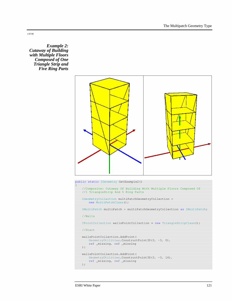
The Multipatch Geometry Type
J-9749
ESRI White Paper 121
Example 2: Cutaway of Building with Multiple Floors
Composed of One Triangle Strip and
Five Ring Parts
public static IGeometry GetExample2() { //Composite: Cutaway Of Building With Multiple Floors Composed Of //1 TriangleStrip And 5 Ring Parts IGeometryCollection multiPatchGeometryCollection = new MultiPatchClass(); IMultiPatch multiPatch = multiPatchGeometryCollection as IMultiPatch; //Walls IPointCollection wallsPointCollection = new TriangleStripClass(); //Start wallsPointCollection.AddPoint( GeometryUtilities.ConstructPoint3D(3, -3, 0), ref _missing, ref _missing ); wallsPointCollection.AddPoint( GeometryUtilities.ConstructPoint3D(3, -3, 16), ref _missing, ref _missing );

The Multipatch Geometry Type
J-9749
December 2008 122
//Right Wall wallsPointCollection.AddPoint( GeometryUtilities.ConstructPoint3D(3, 3, 0), ref _missing, ref _missing ); wallsPointCollection.AddPoint( GeometryUtilities.ConstructPoint3D(3, 3, 16), ref _missing, ref _missing ); //Back Wall wallsPointCollection.AddPoint( GeometryUtilities.ConstructPoint3D(-3, 3, 0), ref _missing, ref _missing ); wallsPointCollection.AddPoint( GeometryUtilities.ConstructPoint3D(-3, 3, 16), ref _missing, ref _missing ); //Left Wall wallsPointCollection.AddPoint( GeometryUtilities.ConstructPoint3D(-3, -3, 0), ref _missing, ref _missing ); wallsPointCollection.AddPoint( GeometryUtilities.ConstructPoint3D(-3, -3, 16), ref _missing, ref _missing ); multiPatchGeometryCollection.AddGeometry( wallsPointCollection as IGeometry, ref _missing, ref _missing ); //Floors //Base IPointCollection basePointCollection = new RingClass(); basePointCollection.AddPoint( GeometryUtilities.ConstructPoint3D(3, 3, 0), ref _missing, ref _missing ); basePointCollection.AddPoint( GeometryUtilities.ConstructPoint3D(3, -3, 0), ref _missing, ref _missing ); basePointCollection.AddPoint( GeometryUtilities.ConstructPoint3D(-3, -3, 0), ref _missing, ref _missing ); basePointCollection.AddPoint( GeometryUtilities.ConstructPoint3D(-3, 3, 0), ref _missing, ref _missing );
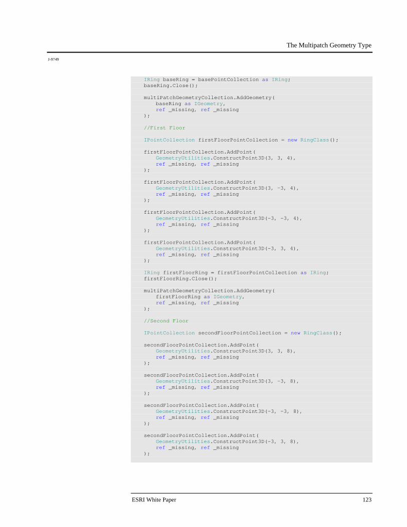
The Multipatch Geometry Type
J-9749
ESRI White Paper 123
IRing baseRing = basePointCollection as IRing; baseRing.Close(); multiPatchGeometryCollection.AddGeometry( baseRing as IGeometry, ref _missing, ref _missing ); //First Floor IPointCollection firstFloorPointCollection = new RingClass(); firstFloorPointCollection.AddPoint( GeometryUtilities.ConstructPoint3D(3, 3, 4), ref _missing, ref _missing ); firstFloorPointCollection.AddPoint( GeometryUtilities.ConstructPoint3D(3, -3, 4), ref _missing, ref _missing ); firstFloorPointCollection.AddPoint( GeometryUtilities.ConstructPoint3D(-3, -3, 4), ref _missing, ref _missing ); firstFloorPointCollection.AddPoint( GeometryUtilities.ConstructPoint3D(-3, 3, 4), ref _missing, ref _missing ); IRing firstFloorRing = firstFloorPointCollection as IRing; firstFloorRing.Close(); multiPatchGeometryCollection.AddGeometry( firstFloorRing as IGeometry, ref _missing, ref _missing ); //Second Floor IPointCollection secondFloorPointCollection = new RingClass(); secondFloorPointCollection.AddPoint( GeometryUtilities.ConstructPoint3D(3, 3, 8), ref _missing, ref _missing ); secondFloorPointCollection.AddPoint( GeometryUtilities.ConstructPoint3D(3, -3, 8), ref _missing, ref _missing ); secondFloorPointCollection.AddPoint( GeometryUtilities.ConstructPoint3D(-3, -3, 8), ref _missing, ref _missing ); secondFloorPointCollection.AddPoint( GeometryUtilities.ConstructPoint3D(-3, 3, 8), ref _missing, ref _missing );
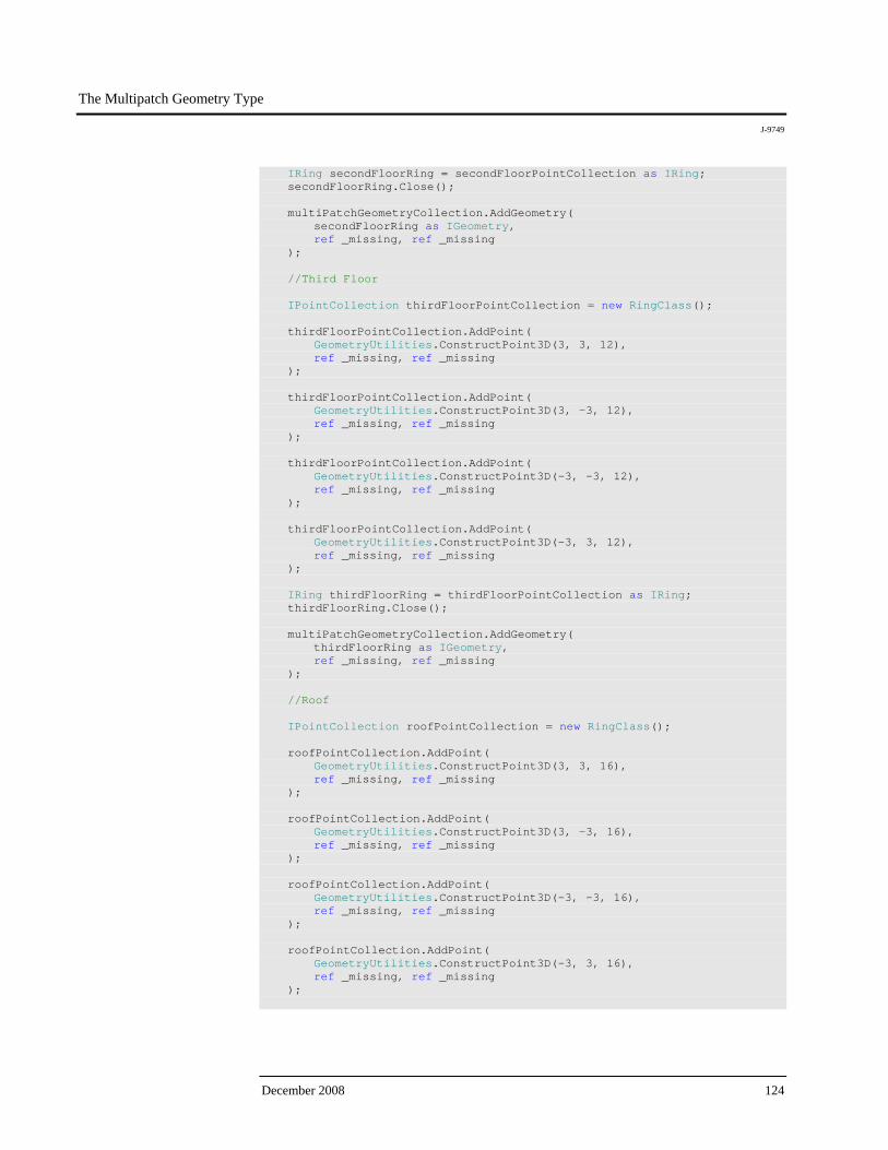
The Multipatch Geometry Type
J-9749
December 2008 124
IRing secondFloorRing = secondFloorPointCollection as IRing; secondFloorRing.Close(); multiPatchGeometryCollection.AddGeometry( secondFloorRing as IGeometry, ref _missing, ref _missing ); //Third Floor IPointCollection thirdFloorPointCollection = new RingClass(); thirdFloorPointCollection.AddPoint( GeometryUtilities.ConstructPoint3D(3, 3, 12), ref _missing, ref _missing ); thirdFloorPointCollection.AddPoint( GeometryUtilities.ConstructPoint3D(3, -3, 12), ref _missing, ref _missing ); thirdFloorPointCollection.AddPoint( GeometryUtilities.ConstructPoint3D(-3, -3, 12), ref _missing, ref _missing ); thirdFloorPointCollection.AddPoint( GeometryUtilities.ConstructPoint3D(-3, 3, 12), ref _missing, ref _missing ); IRing thirdFloorRing = thirdFloorPointCollection as IRing; thirdFloorRing.Close(); multiPatchGeometryCollection.AddGeometry( thirdFloorRing as IGeometry, ref _missing, ref _missing ); //Roof IPointCollection roofPointCollection = new RingClass(); roofPointCollection.AddPoint( GeometryUtilities.ConstructPoint3D(3, 3, 16), ref _missing, ref _missing ); roofPointCollection.AddPoint( GeometryUtilities.ConstructPoint3D(3, -3, 16), ref _missing, ref _missing ); roofPointCollection.AddPoint( GeometryUtilities.ConstructPoint3D(-3, -3, 16), ref _missing, ref _missing ); roofPointCollection.AddPoint( GeometryUtilities.ConstructPoint3D(-3, 3, 16), ref _missing, ref _missing );
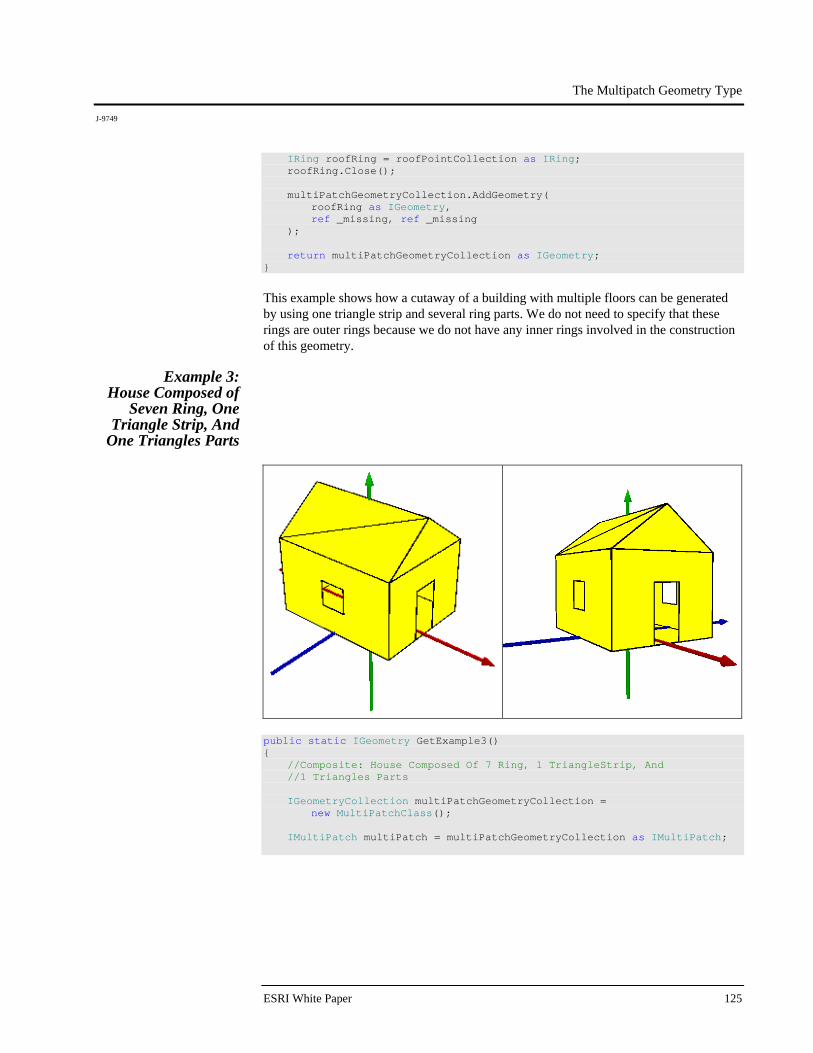
The Multipatch Geometry Type
J-9749
ESRI White Paper 125
IRing roofRing = roofPointCollection as IRing; roofRing.Close(); multiPatchGeometryCollection.AddGeometry( roofRing as IGeometry, ref _missing, ref _missing ); return multiPatchGeometryCollection as IGeometry; }
This example shows how a cutaway of a building with multiple floors can be generated by using one triangle strip and several ring parts. We do not need to specify that these rings are outer rings because we do not have any inner rings involved in the construction of this geometry.
Example 3: House Composed of
Seven Ring, One Triangle Strip, And
One Triangles Parts
public static IGeometry GetExample3() { //Composite: House Composed Of 7 Ring, 1 TriangleStrip, And //1 Triangles Parts IGeometryCollection multiPatchGeometryCollection = new MultiPatchClass(); IMultiPatch multiPatch = multiPatchGeometryCollection as IMultiPatch;

The Multipatch Geometry Type
J-9749
December 2008 126
//Base (Exterior Ring) IPointCollection basePointCollection = new RingClass(); basePointCollection.AddPoint( GeometryUtilities.ConstructPoint3D(5, 4, 0), ref _missing, ref _missing ); basePointCollection.AddPoint( GeometryUtilities.ConstructPoint3D(-5, 4, 0), ref _missing, ref _missing ); basePointCollection.AddPoint( GeometryUtilities.ConstructPoint3D(-5, -4, 0), ref _missing, ref _missing ); basePointCollection.AddPoint( GeometryUtilities.ConstructPoint3D(5, -4, 0), ref _missing, ref _missing ); basePointCollection.AddPoint( basePointCollection.get_Point(0), ref _missing, ref _missing ); multiPatchGeometryCollection.AddGeometry( basePointCollection as IGeometry, ref _missing, ref _missing ); multiPatch.PutRingType( basePointCollection as IRing, esriMultiPatchRingType.esriMultiPatchOuterRing ); //Front With Cutaway For Door (Exterior Ring) IPointCollection frontPointCollection = new RingClass(); frontPointCollection.AddPoint( GeometryUtilities.ConstructPoint3D(5, 4, 6), ref _missing, ref _missing ); frontPointCollection.AddPoint( GeometryUtilities.ConstructPoint3D(5, 4, 0), ref _missing, ref _missing ); frontPointCollection.AddPoint( GeometryUtilities.ConstructPoint3D(5, 1, 0), ref _missing, ref _missing ); frontPointCollection.AddPoint( GeometryUtilities.ConstructPoint3D(5, 1, 4), ref _missing, ref _missing );
The Multipatch Geometry Type
J-9749
ESRI White Paper 127
frontPointCollection.AddPoint( GeometryUtilities.ConstructPoint3D(5, -1, 4), ref _missing, ref _missing ); frontPointCollection.AddPoint( GeometryUtilities.ConstructPoint3D(5, -1, 0), ref _missing, ref _missing ); frontPointCollection.AddPoint( GeometryUtilities.ConstructPoint3D(5, -4, 0), ref _missing, ref _missing ); frontPointCollection.AddPoint( GeometryUtilities.ConstructPoint3D(5, -4, 6), ref _missing, ref _missing ); frontPointCollection.AddPoint( frontPointCollection.get_Point(0), ref _missing, ref _missing ); multiPatchGeometryCollection.AddGeometry( frontPointCollection as IGeometry, ref _missing, ref _missing ); multiPatch.PutRingType( frontPointCollection as IRing, esriMultiPatchRingType.esriMultiPatchOuterRing ); //Back (Exterior Ring) IPointCollection backPointCollection = new RingClass(); backPointCollection.AddPoint( GeometryUtilities.ConstructPoint3D(-5, 4, 6), ref _missing, ref _missing ); backPointCollection.AddPoint( GeometryUtilities.ConstructPoint3D(-5, -4, 6), ref _missing, ref _missing ); backPointCollection.AddPoint( GeometryUtilities.ConstructPoint3D(-5, -4, 0), ref _missing, ref _missing ); backPointCollection.AddPoint( GeometryUtilities.ConstructPoint3D(-5, 4, 0), ref _missing, ref _missing ); backPointCollection.AddPoint( backPointCollection.get_Point(0), ref _missing, ref _missing );

The Multipatch Geometry Type
J-9749
December 2008 128
multiPatchGeometryCollection.AddGeometry( backPointCollection as IGeometry, ref _missing, ref _missing ); multiPatch.PutRingType( backPointCollection as IRing, esriMultiPatchRingType.esriMultiPatchOuterRing ); //Right Side (Ring Group) //Exterior Ring IPointCollection rightSideExteriorPointCollection = new RingClass(); rightSideExteriorPointCollection.AddPoint( GeometryUtilities.ConstructPoint3D(5, 4, 6), ref _missing, ref _missing ); rightSideExteriorPointCollection.AddPoint( GeometryUtilities.ConstructPoint3D(-5, 4, 6), ref _missing, ref _missing ); rightSideExteriorPointCollection.AddPoint( GeometryUtilities.ConstructPoint3D(-5, 4, 0), ref _missing, ref _missing ); rightSideExteriorPointCollection.AddPoint( GeometryUtilities.ConstructPoint3D(5, 4, 0), ref _missing, ref _missing ); rightSideExteriorPointCollection.AddPoint( rightSideExteriorPointCollection.get_Point(0), ref _missing, ref _missing ); multiPatchGeometryCollection.AddGeometry( rightSideExteriorPointCollection as IGeometry, ref _missing, ref _missing ); multiPatch.PutRingType( rightSideExteriorPointCollection as IRing, esriMultiPatchRingType.esriMultiPatchOuterRing ); //Interior Ring IPointCollection rightSideInteriorPointCollection = new RingClass(); rightSideInteriorPointCollection.AddPoint( GeometryUtilities.ConstructPoint3D(1, 4, 4), ref _missing, ref _missing ); rightSideInteriorPointCollection.AddPoint( GeometryUtilities.ConstructPoint3D(1, 4, 2), ref _missing, ref _missing );

The Multipatch Geometry Type
J-9749
ESRI White Paper 129
rightSideInteriorPointCollection.AddPoint( GeometryUtilities.ConstructPoint3D(-1, 4, 2), ref _missing, ref _missing ); rightSideInteriorPointCollection.AddPoint( GeometryUtilities.ConstructPoint3D(-1, 4, 4), ref _missing, ref _missing ); rightSideInteriorPointCollection.AddPoint( rightSideInteriorPointCollection.get_Point(0), ref _missing, ref _missing ); multiPatchGeometryCollection.AddGeometry( rightSideInteriorPointCollection as IGeometry, ref _missing, ref _missing ); multiPatch.PutRingType( rightSideInteriorPointCollection as IRing, esriMultiPatchRingType.esriMultiPatchInnerRing ); //Left Side (Ring Group) //Exterior Ring IPointCollection leftSideExteriorPointCollection = new RingClass(); leftSideExteriorPointCollection.AddPoint( GeometryUtilities.ConstructPoint3D(5, -4, 6), ref _missing, ref _missing ); leftSideExteriorPointCollection.AddPoint( GeometryUtilities.ConstructPoint3D(5, -4, 0), ref _missing, ref _missing ); leftSideExteriorPointCollection.AddPoint( GeometryUtilities.ConstructPoint3D(-5, -4, 0), ref _missing, ref _missing ); leftSideExteriorPointCollection.AddPoint( GeometryUtilities.ConstructPoint3D(-5, -4, 6), ref _missing, ref _missing ); leftSideExteriorPointCollection.AddPoint( leftSideExteriorPointCollection.get_Point(0), ref _missing, ref _missing ); multiPatchGeometryCollection.AddGeometry( leftSideExteriorPointCollection as IGeometry, ref _missing, ref _missing ); multiPatch.PutRingType( leftSideExteriorPointCollection as IRing, esriMultiPatchRingType.esriMultiPatchOuterRing );

The Multipatch Geometry Type
J-9749
December 2008 130
//Interior Ring IPointCollection leftSideInteriorPointCollection = new RingClass(); leftSideInteriorPointCollection.AddPoint( GeometryUtilities.ConstructPoint3D(1, -4, 4), ref _missing, ref _missing ); leftSideInteriorPointCollection.AddPoint( GeometryUtilities.ConstructPoint3D(-1, -4, 4), ref _missing, ref _missing ); leftSideInteriorPointCollection.AddPoint( GeometryUtilities.ConstructPoint3D(-1, -4, 2), ref _missing, ref _missing ); leftSideInteriorPointCollection.AddPoint( GeometryUtilities.ConstructPoint3D(1, -4, 2), ref _missing, ref _missing ); leftSideInteriorPointCollection.AddPoint( leftSideInteriorPointCollection.get_Point(0), ref _missing, ref _missing ); multiPatchGeometryCollection.AddGeometry( leftSideInteriorPointCollection as IGeometry, ref _missing, ref _missing ); multiPatch.PutRingType( leftSideInteriorPointCollection as IRing, esriMultiPatchRingType.esriMultiPatchInnerRing ); //Roof IPointCollection roofPointCollection = new TriangleStripClass(); roofPointCollection.AddPoint( GeometryUtilities.ConstructPoint3D(-5, 4, 6), ref _missing, ref _missing ); roofPointCollection.AddPoint( GeometryUtilities.ConstructPoint3D(5, 4, 6), ref _missing, ref _missing ); roofPointCollection.AddPoint( GeometryUtilities.ConstructPoint3D(-5, 0, 9), ref _missing, ref _missing ); roofPointCollection.AddPoint( GeometryUtilities.ConstructPoint3D(5, 0, 9), ref _missing, ref _missing );
The Multipatch Geometry Type
J-9749
ESRI White Paper 131
roofPointCollection.AddPoint( GeometryUtilities.ConstructPoint3D(-5, -4, 6), ref _missing, ref _missing ); roofPointCollection.AddPoint( GeometryUtilities.ConstructPoint3D(5, -4, 6), ref _missing, ref _missing ); multiPatchGeometryCollection.AddGeometry( roofPointCollection as IGeometry, ref _missing, ref _missing ); //Triangular Area Between Roof And Front/Back IPointCollection triangularAreaPointCollection = new TrianglesClass(); //Area Between Roof And Front triangularAreaPointCollection.AddPoint( GeometryUtilities.ConstructPoint3D(5, 0, 9), ref _missing, ref _missing ); triangularAreaPointCollection.AddPoint( GeometryUtilities.ConstructPoint3D(5, 4, 6), ref _missing, ref _missing ); triangularAreaPointCollection.AddPoint( GeometryUtilities.ConstructPoint3D(5, -4, 6), ref _missing, ref _missing ); //Area Between Roof And Back triangularAreaPointCollection.AddPoint( GeometryUtilities.ConstructPoint3D(-5, 0, 9), ref _missing, ref _missing ); triangularAreaPointCollection.AddPoint( GeometryUtilities.ConstructPoint3D(-5, -4, 6), ref _missing, ref _missing ); triangularAreaPointCollection.AddPoint( GeometryUtilities.ConstructPoint3D(-5, 4, 6), ref _missing, ref _missing ); multiPatchGeometryCollection.AddGeometry( triangularAreaPointCollection as IGeometry, ref _missing, ref _missing ); return multiPatchGeometryCollection as IGeometry; }
A house with windows and a cutaway for a door can be constructed by assessing the kinds of patches that would best represent each face of the house and proceeding to add each patch one by one to the multipatch container. In this example, we use an outer ring/inner ring combination for each side of the house that has a window; an outer ring
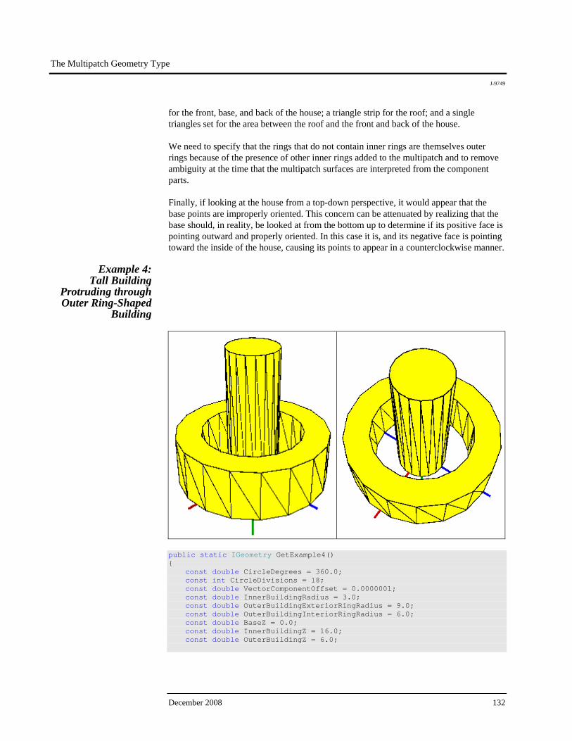
The Multipatch Geometry Type
J-9749
December 2008 132
for the front, base, and back of the house; a triangle strip for the roof; and a single triangles set for the area between the roof and the front and back of the house. We need to specify that the rings that do not contain inner rings are themselves outer rings because of the presence of other inner rings added to the multipatch and to remove ambiguity at the time that the multipatch surfaces are interpreted from the component parts. Finally, if looking at the house from a top-down perspective, it would appear that the base points are improperly oriented. This concern can be attenuated by realizing that the base should, in reality, be looked at from the bottom up to determine if its positive face is pointing outward and properly oriented. In this case it is, and its negative face is pointing toward the inside of the house, causing its points to appear in a counterclockwise manner.
Example 4: Tall Building
Protruding through Outer Ring-Shaped
Building
public static IGeometry GetExample4() { const double CircleDegrees = 360.0; const int CircleDivisions = 18; const double VectorComponentOffset = 0.0000001; const double InnerBuildingRadius = 3.0; const double OuterBuildingExteriorRingRadius = 9.0; const double OuterBuildingInteriorRingRadius = 6.0; const double BaseZ = 0.0; const double InnerBuildingZ = 16.0; const double OuterBuildingZ = 6.0;
The Multipatch Geometry Type
J-9749
ESRI White Paper 133
//Composite: Tall Building Protruding Through Outer //Ring-Shaped Building IMultiPatch multiPatch = new MultiPatchClass(); IGeometryCollection multiPatchGeometryCollection = multiPatch as IGeometryCollection; IPoint originPoint = GeometryUtilities.ConstructPoint3D(0, 0, 0); IVector3D upperAxisVector3D = GeometryUtilities.ConstructVector3D(0, 0, 10); IVector3D lowerAxisVector3D = GeometryUtilities.ConstructVector3D(0, 0, -10); lowerAxisVector3D.XComponent += VectorComponentOffset; IVector3D normalVector3D = upperAxisVector3D.CrossProduct(lowerAxisVector3D) as IVector3D; double rotationAngleInRadians = GeometryUtilities.GetRadians(CircleDegrees / CircleDivisions); //Inner Building IGeometry innerBuildingBaseGeometry = new PolygonClass(); IPointCollection innerBuildingBasePointCollection = innerBuildingBaseGeometry as IPointCollection; //Outer Building IGeometry outerBuildingBaseGeometry = new PolygonClass(); IGeometryCollection outerBuildingBaseGeometryCollection = outerBuildingBaseGeometry as IGeometryCollection; IPointCollection outerBuildingBaseExteriorRingPointCollection = new RingClass(); IPointCollection outerBuildingBaseInteriorRingPointCollection = new RingClass(); for (int i = 0; i < CircleDivisions; i++) { normalVector3D.Rotate( -1 * rotationAngleInRadians, upperAxisVector3D ); //Inner Building normalVector3D.Magnitude = InnerBuildingRadius; IPoint innerBuildingBaseVertexPoint = GeometryUtilities.ConstructPoint2D( originPoint.X + normalVector3D.XComponent, originPoint.Y + normalVector3D.YComponent ); innerBuildingBasePointCollection.AddPoint( innerBuildingBaseVertexPoint, ref _missing, ref _missing );
The Multipatch Geometry Type
J-9749
December 2008 134
//Outer Building //Exterior Ring normalVector3D.Magnitude = OuterBuildingExteriorRingRadius; IPoint outerBuildingBaseExteriorRingVertexPoint = GeometryUtilities.ConstructPoint2D( originPoint.X + normalVector3D.XComponent, originPoint.Y + normalVector3D.YComponent ); outerBuildingBaseExteriorRingPointCollection.AddPoint( outerBuildingBaseExteriorRingVertexPoint, ref _missing, ref _missing ); //Interior Ring normalVector3D.Magnitude = OuterBuildingInteriorRingRadius; IPoint outerBuildingBaseInteriorRingVertexPoint = GeometryUtilities.ConstructPoint2D( originPoint.X + normalVector3D.XComponent, originPoint.Y + normalVector3D.YComponent ); outerBuildingBaseInteriorRingPointCollection.AddPoint( outerBuildingBaseInteriorRingVertexPoint, ref _missing, ref _missing ); } IPolygon innerBuildingBasePolygon = innerBuildingBaseGeometry as IPolygon; innerBuildingBasePolygon.Close(); IRing outerBuildingBaseExteriorRing = outerBuildingBaseExteriorRingPointCollection as IRing; outerBuildingBaseExteriorRing.Close(); IRing outerBuildingBaseInteriorRing = outerBuildingBaseInteriorRingPointCollection as IRing; outerBuildingBaseInteriorRing.Close(); outerBuildingBaseInteriorRing.ReverseOrientation(); outerBuildingBaseGeometryCollection.AddGeometry( outerBuildingBaseExteriorRing as IGeometry, ref _missing, ref _missing ); outerBuildingBaseGeometryCollection.AddGeometry( outerBuildingBaseInteriorRing as IGeometry, ref _missing, ref _missing ); ITopologicalOperator topologicalOperator = outerBuildingBaseGeometry as ITopologicalOperator; topologicalOperator.Simplify();
The Multipatch Geometry Type
J-9749
ESRI White Paper 135
IConstructMultiPatch innerBuildingConstructMultiPatch = new MultiPatchClass(); innerBuildingConstructMultiPatch.ConstructExtrudeFromTo( BaseZ, InnerBuildingZ, innerBuildingBaseGeometry ); IGeometryCollection innerBuildingPatchGeometryCollection = innerBuildingConstructMultiPatch as IGeometryCollection; for ( int i = 0; i < innerBuildingPatchGeometryCollection.GeometryCount; i++ ) { multiPatchGeometryCollection.AddGeometry( innerBuildingPatchGeometryCollection.get_Geometry(i), ref _missing, ref _missing ); } IConstructMultiPatch outerBuildingConstructMultiPatch = new MultiPatchClass(); outerBuildingConstructMultiPatch.ConstructExtrudeFromTo( BaseZ, OuterBuildingZ, outerBuildingBaseGeometry ); IMultiPatch outerBuildingMultiPatch = outerBuildingConstructMultiPatch as IMultiPatch; IGeometryCollection outerBuildingPatchGeometryCollection = outerBuildingConstructMultiPatch as IGeometryCollection; for ( int i = 0; i < outerBuildingPatchGeometryCollection.GeometryCount; i++ ) { IGeometry outerBuildingPatchGeometry = outerBuildingPatchGeometryCollection.get_Geometry(i); multiPatchGeometryCollection.AddGeometry( outerBuildingPatchGeometry, ref _missing, ref _missing ); if ( outerBuildingPatchGeometry.GeometryType == esriGeometryType.esriGeometryRing ) { bool isBeginningRing = false; esriMultiPatchRingType multiPatchRingType = outerBuildingMultiPatch.GetRingType( outerBuildingPatchGeometry as IRing, ref isBeginningRing );
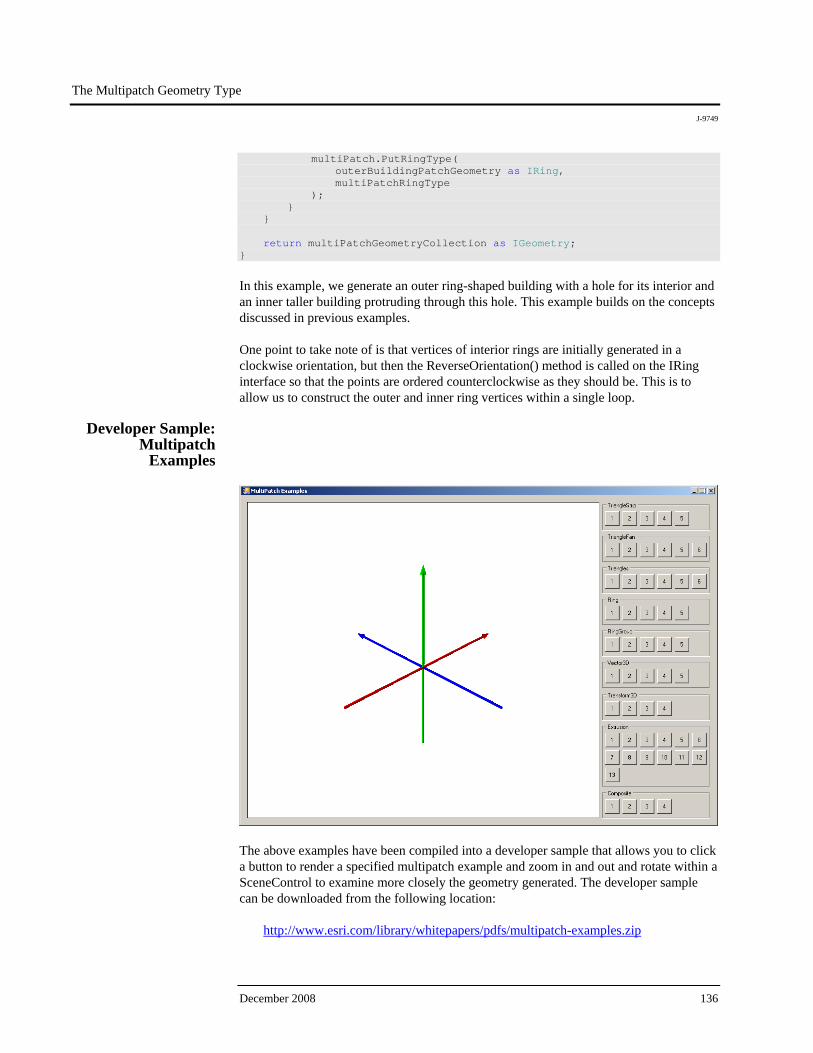
The Multipatch Geometry Type
J-9749
December 2008 136
multiPatch.PutRingType( outerBuildingPatchGeometry as IRing, multiPatchRingType ); } } return multiPatchGeometryCollection as IGeometry; }
In this example, we generate an outer ring-shaped building with a hole for its interior and an inner taller building protruding through this hole. This example builds on the concepts discussed in previous examples. One point to take note of is that vertices of interior rings are initially generated in a clockwise orientation, but then the ReverseOrientation() method is called on the IRing interface so that the points are ordered counterclockwise as they should be. This is to allow us to construct the outer and inner ring vertices within a single loop.
Developer Sample: Multipatch
Examples
The above examples have been compiled into a developer sample that allows you to click a button to render a specified multipatch example and zoom in and out and rotate within a SceneControl to examine more closely the geometry generated. The developer sample can be downloaded from the following location:
http://www.esri.com/library/whitepapers/pdfs/multipatch-examples.zip
The Multipatch Geometry Type
J-9749
ESRI White Paper 137
This developer sample has been written in C# and can be compiled from source and run as a console application on a machine that has, at minimum, an ArcGIS Engine license and either Visual Studio® 2005 or Visual C#® Express installed. The benefit of this developer sample is that you can conveniently focus on construction of the multipatch geometry and ignore details surrounding the proper rendering of the geometry in a 3D viewer. You can also experiment with modifying the examples provided to generate new multipatch geometries and always go back to the original examples as a starting point if problems arise. If you would then like to learn how the geometry can be rendered, you can look at the code provided to learn how this can be accomplished. A note about the example code contained within this document: Calls to methods such as ConstructPoint3D() and ConstructVector3D() are made without reference to the definition of these functions to reduce the amount of code needed to be written. The function definitions are included below and can be alternatively accessed by viewing the source code of the developer sample. // Defined Within Each Static Class As Placeholder For Missing Parameters private static object _missing = Type.Missing; // Used To Specify Z Awareness Of Geometries public static void MakeZAware(IGeometry geometry) { IZAware zAware = geometry as IZAware; zAware.ZAware = true; } // Used To Construct 3D Vectors public static IVector3D ConstructVector3D ( double xComponent, double yComponent, double zComponent ) { IVector3D vector3D = new Vector3DClass(); vector3D.SetComponents(xComponent, yComponent, zComponent); return vector3D; } // Used To Convert Between Decimal Degrees And Radians public static double GetRadians(double decimalDegrees) { return decimalDegrees * (Math.PI / 180); }
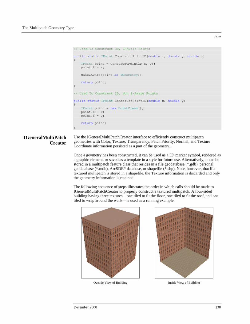
The Multipatch Geometry Type
J-9749
December 2008 138
// Used To Construct 3D, Z-Aware Points public static IPoint ConstructPoint3D(double x, double y, double z) { IPoint point = ConstructPoint2D(x, y); point.Z = z; MakeZAware(point as IGeometry); return point; } // Used To Construct 2D, Non Z-Aware Points public static IPoint ConstructPoint2D(double x, double y) { IPoint point = new PointClass(); point.X = x; point.Y = y; return point;
}
IGeneralMultiPatch Creator
Use the IGeneralMultiPatchCreator interface to efficiently construct multipatch geometries with Color, Texture, Transparency, Patch Priority, Normal, and Texture Coordinate information persisted as a part of the geometry. Once a geometry has been constructed, it can be used as a 3D marker symbol, rendered as a graphic element, or saved as a template in a style for future use. Alternatively, it can be stored in a multipatch feature class that resides in a file geodatabase (*.gdb), personal geodatabase (*.mdb), ArcSDE® database, or shapefile (*.shp). Note, however, that if a textured multipatch is stored in a shapefile, the Texture information is discarded and only the geometry information is retained. The following sequence of steps illustrates the order in which calls should be made to IGeneralMultiPatchCreator to properly construct a textured multipatch. A four-sided building having three textures—one tiled to fit the floor, one tiled to fit the roof, and one tiled to wrap around the walls—is used as a running example.
Outside View of Building
Inside View of Building
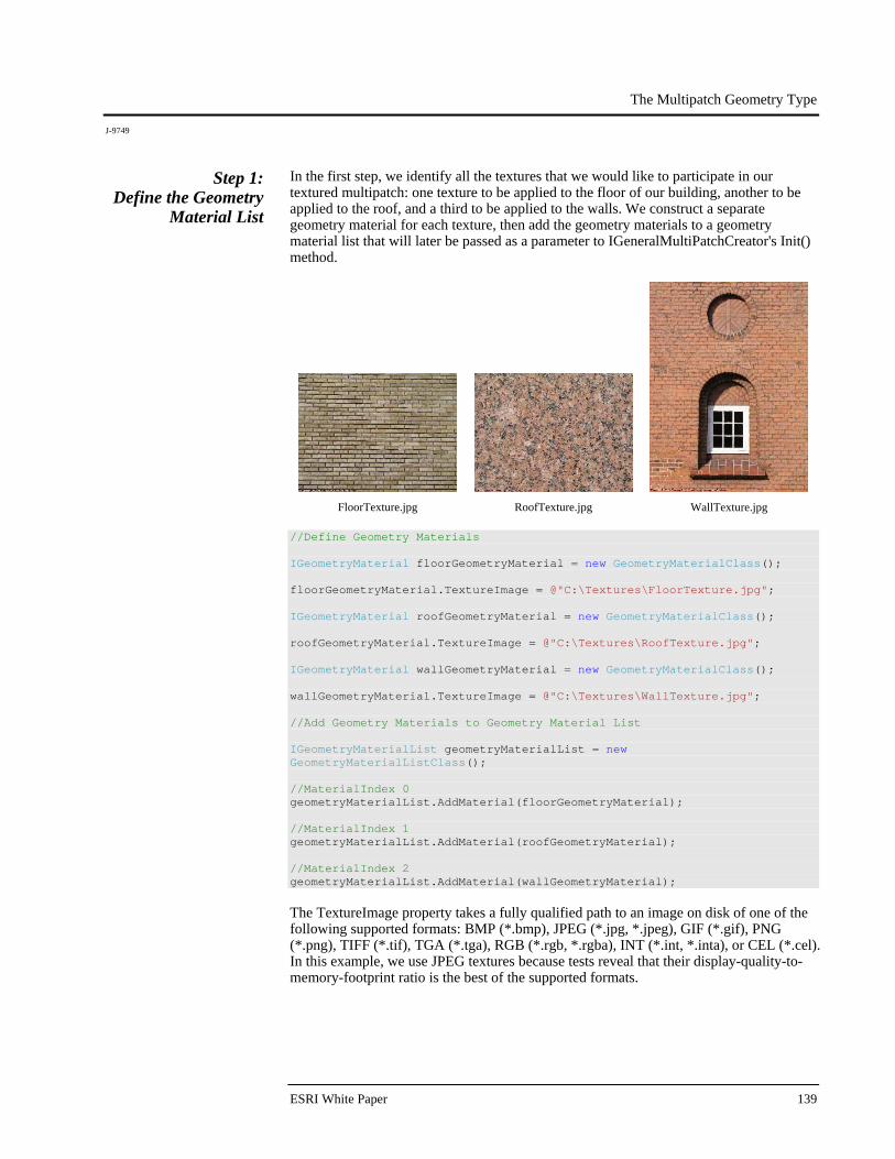
The Multipatch Geometry Type
J-9749
ESRI White Paper 139
Step 1: Define the Geometry
Material List
In the first step, we identify all the textures that we would like to participate in our textured multipatch: one texture to be applied to the floor of our building, another to be applied to the roof, and a third to be applied to the walls. We construct a separate geometry material for each texture, then add the geometry materials to a geometry material list that will later be passed as a parameter to IGeneralMultiPatchCreator's Init() method.
FloorTexture.jpg
RoofTexture.jpg
WallTexture.jpg
//Define Geometry Materials IGeometryMaterial floorGeometryMaterial = new GeometryMaterialClass(); floorGeometryMaterial.TextureImage = @"C:\Textures\FloorTexture.jpg"; IGeometryMaterial roofGeometryMaterial = new GeometryMaterialClass(); roofGeometryMaterial.TextureImage = @"C:\Textures\RoofTexture.jpg"; IGeometryMaterial wallGeometryMaterial = new GeometryMaterialClass(); wallGeometryMaterial.TextureImage = @"C:\Textures\WallTexture.jpg"; //Add Geometry Materials to Geometry Material List IGeometryMaterialList geometryMaterialList = new GeometryMaterialListClass(); //MaterialIndex 0 geometryMaterialList.AddMaterial(floorGeometryMaterial); //MaterialIndex 1 geometryMaterialList.AddMaterial(roofGeometryMaterial); //MaterialIndex 2 geometryMaterialList.AddMaterial(wallGeometryMaterial); The TextureImage property takes a fully qualified path to an image on disk of one of the following supported formats: BMP (*.bmp), JPEG (*.jpg, *.jpeg), GIF (*.gif), PNG (*.png), TIFF (*.tif), TGA (*.tga), RGB (*.rgb, *.rgba), INT (*.int, *.inta), or CEL (*.cel). In this example, we use JPEG textures because tests reveal that their display-quality-to-memory-footprint ratio is the best of the supported formats.
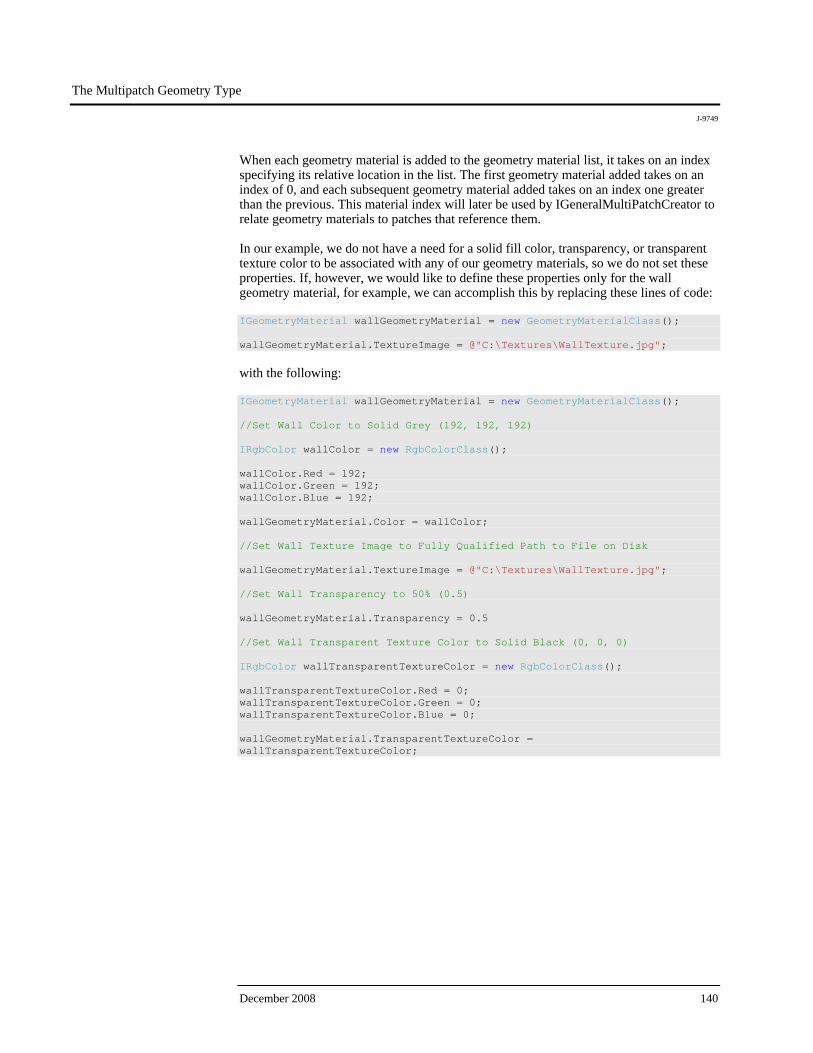
The Multipatch Geometry Type
J-9749
December 2008 140
When each geometry material is added to the geometry material list, it takes on an index specifying its relative location in the list. The first geometry material added takes on an index of 0, and each subsequent geometry material added takes on an index one greater than the previous. This material index will later be used by IGeneralMultiPatchCreator to relate geometry materials to patches that reference them. In our example, we do not have a need for a solid fill color, transparency, or transparent texture color to be associated with any of our geometry materials, so we do not set these properties. If, however, we would like to define these properties only for the wall geometry material, for example, we can accomplish this by replacing these lines of code: IGeometryMaterial wallGeometryMaterial = new GeometryMaterialClass(); wallGeometryMaterial.TextureImage = @"C:\Textures\WallTexture.jpg"; with the following: IGeometryMaterial wallGeometryMaterial = new GeometryMaterialClass(); //Set Wall Color to Solid Grey (192, 192, 192) IRgbColor wallColor = new RgbColorClass(); wallColor.Red = 192; wallColor.Green = 192; wallColor.Blue = 192; wallGeometryMaterial.Color = wallColor; //Set Wall Texture Image to Fully Qualified Path to File on Disk wallGeometryMaterial.TextureImage = @"C:\Textures\WallTexture.jpg"; //Set Wall Transparency to 50% (0.5) wallGeometryMaterial.Transparency = 0.5 //Set Wall Transparent Texture Color to Solid Black (0, 0, 0) IRgbColor wallTransparentTextureColor = new RgbColorClass(); wallTransparentTextureColor.Red = 0; wallTransparentTextureColor.Green = 0; wallTransparentTextureColor.Blue = 0; wallGeometryMaterial.TransparentTextureColor = wallTransparentTextureColor;
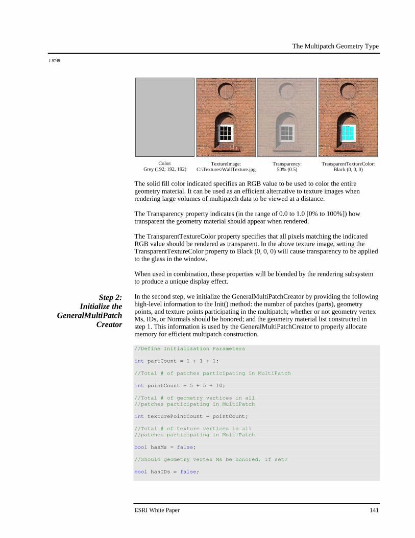
The Multipatch Geometry Type
J-9749
ESRI White Paper 141
Color: Grey (192, 192, 192)
TextureImage: C:\Textures\WallTexture.jpg
Transparency: 50% (0.5)
TransparentTextureColor:Black (0, 0, 0)
The solid fill color indicated specifies an RGB value to be used to color the entire geometry material. It can be used as an efficient alternative to texture images when rendering large volumes of multipatch data to be viewed at a distance. The Transparency property indicates (in the range of 0.0 to 1.0 [0% to 100%]) how transparent the geometry material should appear when rendered. The TransparentTextureColor property specifies that all pixels matching the indicated RGB value should be rendered as transparent. In the above texture image, setting the TransparentTextureColor property to Black (0, 0, 0) will cause transparency to be applied to the glass in the window. When used in combination, these properties will be blended by the rendering subsystem to produce a unique display effect.
Step 2: Initialize the
GeneralMultiPatch Creator
In the second step, we initialize the GeneralMultiPatchCreator by providing the following high-level information to the Init() method: the number of patches (parts), geometry points, and texture points participating in the multipatch; whether or not geometry vertex Ms, IDs, or Normals should be honored; and the geometry material list constructed in step 1. This information is used by the GeneralMultiPatchCreator to properly allocate memory for efficient multipatch construction. //Define Initialization Parameters int partCount = 1 + 1 + 1; //Total # of patches participating in MultiPatch int pointCount = 5 + 5 + 10; //Total # of geometry vertices in all //patches participating in MultiPatch int texturePointCount = pointCount; //Total # of texture vertices in all //patches participating in MultiPatch bool hasMs = false; //Should geometry vertex Ms be honored, if set? bool hasIDs = false;
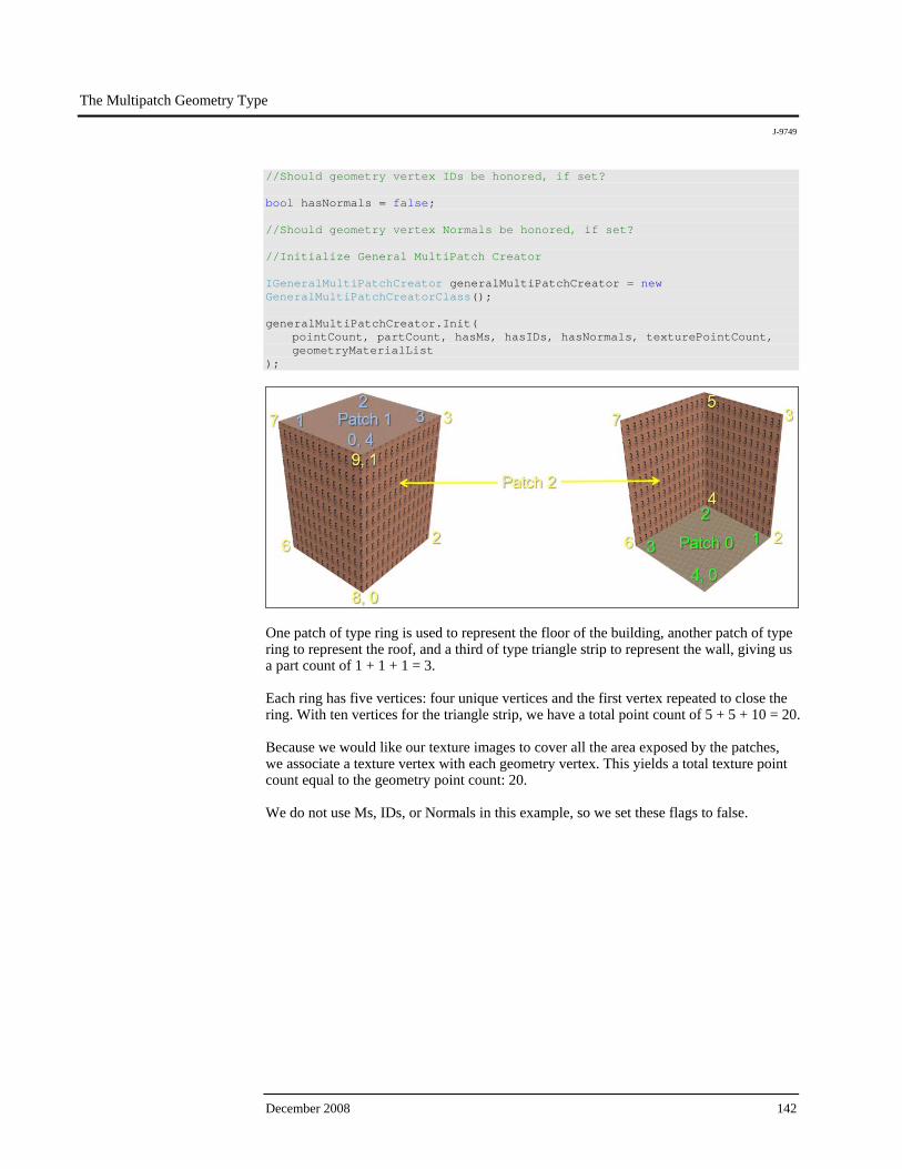
The Multipatch Geometry Type
J-9749
December 2008 142
//Should geometry vertex IDs be honored, if set? bool hasNormals = false; //Should geometry vertex Normals be honored, if set? //Initialize General MultiPatch Creator IGeneralMultiPatchCreator generalMultiPatchCreator = new GeneralMultiPatchCreatorClass(); generalMultiPatchCreator.Init( pointCount, partCount, hasMs, hasIDs, hasNormals, texturePointCount, geometryMaterialList );
One patch of type ring is used to represent the floor of the building, another patch of type ring to represent the roof, and a third of type triangle strip to represent the wall, giving us a part count of 1 + 1 + 1 = 3. Each ring has five vertices: four unique vertices and the first vertex repeated to close the ring. With ten vertices for the triangle strip, we have a total point count of 5 + 5 + 10 = 20. Because we would like our texture images to cover all the area exposed by the patches, we associate a texture vertex with each geometry vertex. This yields a total texture point count equal to the geometry point count: 20. We do not use Ms, IDs, or Normals in this example, so we set these flags to false.
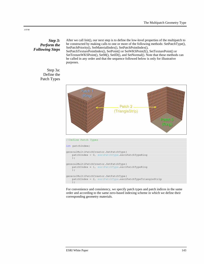
The Multipatch Geometry Type
J-9749
ESRI White Paper 143
Step 3: Perform the
Following Steps
After we call Init(), our next step is to define the low-level properties of the multipatch to be constructed by making calls to one or more of the following methods: SetPatchType(), SetPatchPriority(), SetMaterialIndex(), SetPatchPointIndex(), SetPatchTexturePointIndex(), SetPoint() or SetWKSPointZ(), SetTexturePoint() or SetTextureWKSPoint(), SetM(), SetID(), and SetNormal(). Note that these methods can be called in any order and that the sequence followed below is only for illustrative purposes.
Step 3a: Define the
Patch Types
//Define Patch Types int patchIndex; generalMultiPatchCreator.SetPatchType( patchIndex = 0, esriPatchType.esriPatchTypeRing ); generalMultiPatchCreator.SetPatchType( patchIndex = 1, esriPatchType.esriPatchTypeRing ); generalMultiPatchCreator.SetPatchType( patchIndex = 2, esriPatchType.esriPatchTypeTriangleStrip ); For convenience and consistency, we specify patch types and patch indices in the same order and according to the same zero-based indexing scheme in which we define their corresponding geometry materials.
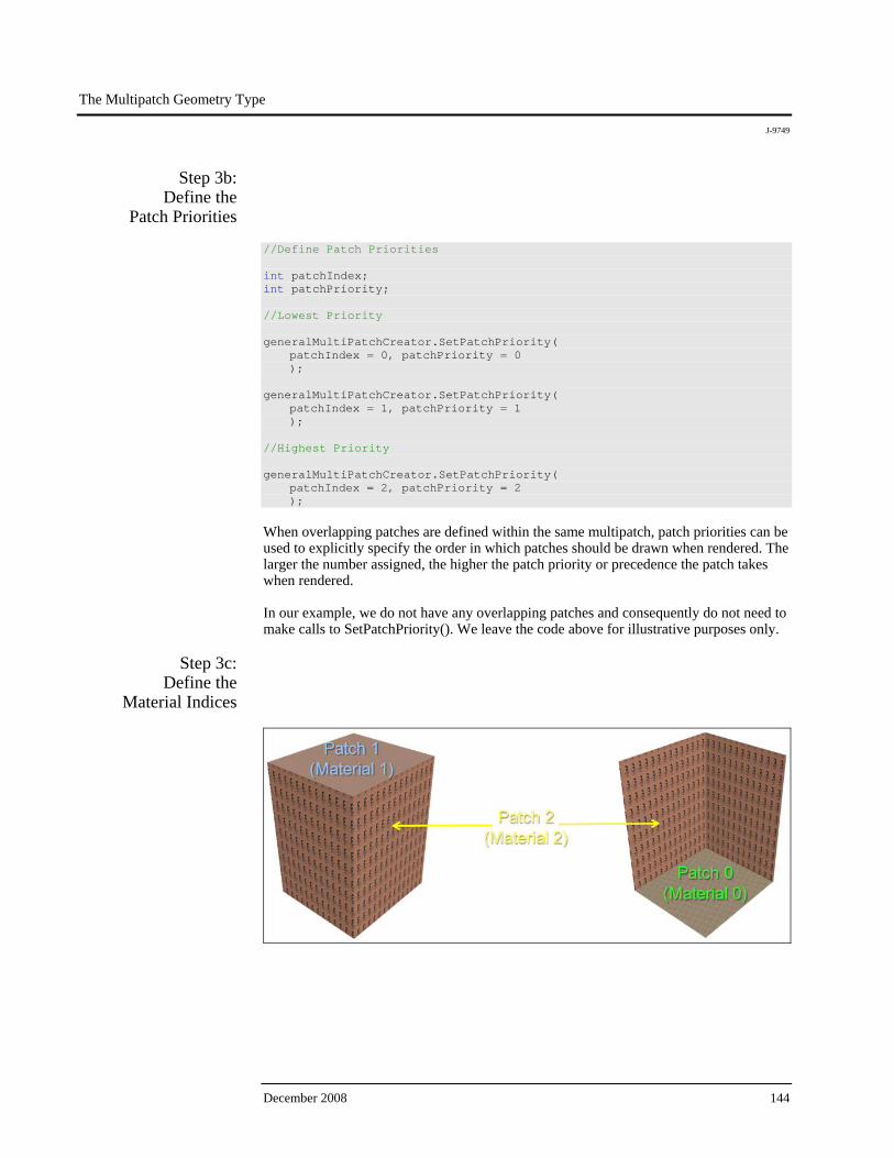
The Multipatch Geometry Type
J-9749
December 2008 144
Step 3b: Define the
Patch Priorities
//Define Patch Priorities int patchIndex; int patchPriority; //Lowest Priority generalMultiPatchCreator.SetPatchPriority( patchIndex = 0, patchPriority = 0 ); generalMultiPatchCreator.SetPatchPriority( patchIndex = 1, patchPriority = 1 ); //Highest Priority generalMultiPatchCreator.SetPatchPriority( patchIndex = 2, patchPriority = 2 ); When overlapping patches are defined within the same multipatch, patch priorities can be used to explicitly specify the order in which patches should be drawn when rendered. The larger the number assigned, the higher the patch priority or precedence the patch takes when rendered. In our example, we do not have any overlapping patches and consequently do not need to make calls to SetPatchPriority(). We leave the code above for illustrative purposes only.
Step 3c: Define the
Material Indices
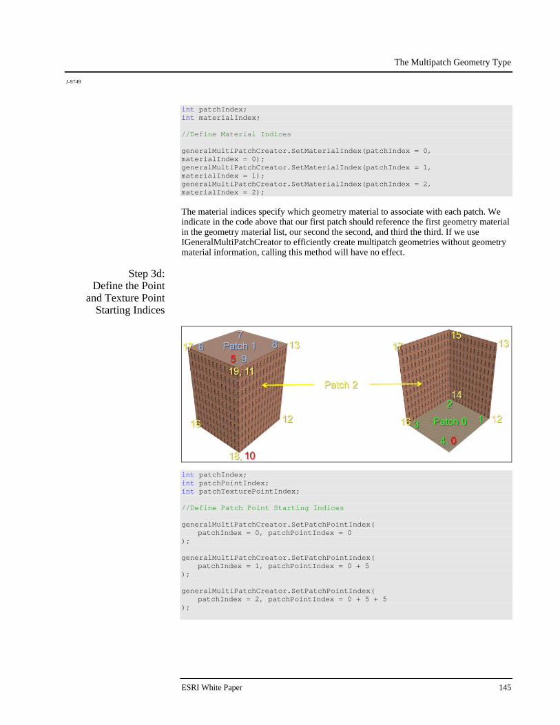
The Multipatch Geometry Type
J-9749
ESRI White Paper 145
int patchIndex; int materialIndex; //Define Material Indices generalMultiPatchCreator.SetMaterialIndex(patchIndex = 0, materialIndex = 0); generalMultiPatchCreator.SetMaterialIndex(patchIndex = 1, materialIndex = 1); generalMultiPatchCreator.SetMaterialIndex(patchIndex = 2, materialIndex = 2); The material indices specify which geometry material to associate with each patch. We indicate in the code above that our first patch should reference the first geometry material in the geometry material list, our second the second, and third the third. If we use IGeneralMultiPatchCreator to efficiently create multipatch geometries without geometry material information, calling this method will have no effect.
Step 3d: Define the Point
and Texture Point Starting Indices
int patchIndex; int patchPointIndex; int patchTexturePointIndex; //Define Patch Point Starting Indices generalMultiPatchCreator.SetPatchPointIndex( patchIndex = 0, patchPointIndex = 0 ); generalMultiPatchCreator.SetPatchPointIndex( patchIndex = 1, patchPointIndex = 0 + 5 ); generalMultiPatchCreator.SetPatchPointIndex( patchIndex = 2, patchPointIndex = 0 + 5 + 5 );

The Multipatch Geometry Type
J-9749
December 2008 146
//Define Patch Texture Point Starting Indices generalMultiPatchCreator.SetPatchTexturePointIndex( patchIndex = 0, patchTexturePointIndex = 0 ); generalMultiPatchCreator.SetPatchTexturePointIndex( patchIndex = 1, patchTexturePointIndex = 0 + 5 ); generalMultiPatchCreator.SetPatchTexturePointIndex( patchIndex = 2, patchTexturePointIndex = 0 + 5 + 5 ); Two buffers are used internally to store geometry and texture vertex information for all patches participating in the construction of the multipatch: one buffer contains the list of geometry vertices and the other contains the list of texture vertices. To properly relate geometry and texture vertices with the corresponding patch they define, the GeneralMultiPatchCreator uses an offset or starting index to indicate where in each list the starting geometry vertex and texture vertex for each patch can be located. The starting geometry vertex index for the first patch is 0; the starting geometry vertex for the second is 0 + 5 = 5, as the first patch, a ring, has five vertices; and the starting geometry vertex for the third is 0 + 5 + 5 = 10, as the second patch, a ring, also has five vertices. Because we have the same number of texture and geometry vertices, the same offsets apply equally to both.
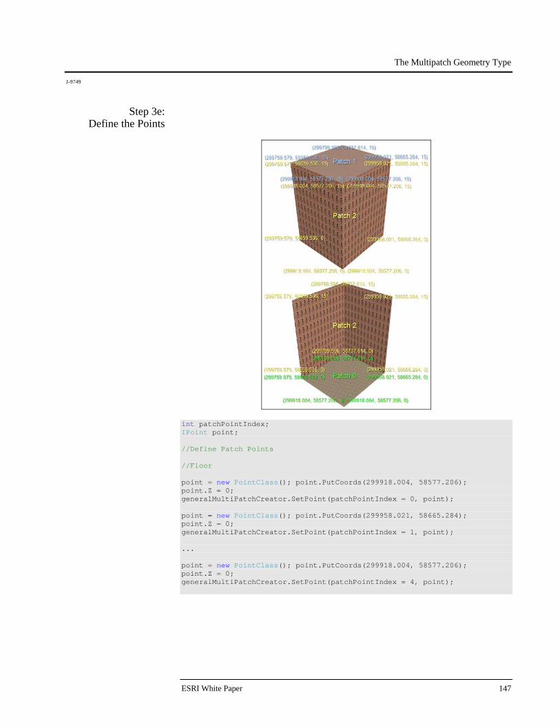
The Multipatch Geometry Type
J-9749
ESRI White Paper 147
Step 3e: Define the Points
int patchPointIndex; IPoint point; //Define Patch Points //Floor point = new PointClass(); point.PutCoords(299918.004, 58577.206); point.Z = 0; generalMultiPatchCreator.SetPoint(patchPointIndex = 0, point); point = new PointClass(); point.PutCoords(299958.021, 58665.284); point.Z = 0; generalMultiPatchCreator.SetPoint(patchPointIndex = 1, point); ... point = new PointClass(); point.PutCoords(299918.004, 58577.206); point.Z = 0; generalMultiPatchCreator.SetPoint(patchPointIndex = 4, point);

The Multipatch Geometry Type
J-9749
December 2008 148
//Roof point = new PointClass(); point.PutCoords(299918.004, 58577.206); point.Z = 15; generalMultiPatchCreator.SetPoint(patchPointIndex = 5, point); point = new PointClass(); point.PutCoords(299958.021, 58665.284); point.Z = 15; generalMultiPatchCreator.SetPoint(patchPointIndex = 6, point); ... point = new PointClass(); point.PutCoords(299918.004, 58577.206); point.Z = 15; generalMultiPatchCreator.SetPoint(patchPointIndex = 9, point); //Wall point = new PointClass(); point.PutCoords(299918.004, 58577.206); point.Z = 0; generalMultiPatchCreator.SetPoint(patchPointIndex = 10, point); point = new PointClass(); point.PutCoords(299918.004, 58577.206); point.Z = 15; generalMultiPatchCreator.SetPoint(patchPointIndex = 11, point); ... point = new PointClass(); point.PutCoords(299918.004, 58577.206); point.Z = 15; generalMultiPatchCreator.SetPoint(patchPointIndex = 19, point); Geometry vertices are then defined using the GeneralMultiPatchCreator SetPoint() method, following the conventions of the patch type they are associated with (rings must be closed, for example). As mentioned in the previous step, the point indices specify where in the list of all geometry vertices the point can be located. The first three vertices of the roof and wall patches are oriented clockwise to explicitly indicate, according to multipatch conventions, that the front sides of these patches should face outward. The first three vertices of the floor patch, however, are oriented counterclockwise so that the front side of this patch faces inward. This is done intentionally so that culling the front side of the multipatch faces in ArcGlobe™ or ArcScene™ allows the floor patch to still be visible, as in the above illustrations. The SetWKSPointZ() method can be used in conjunction with WKSPointZ struct representing each point as an efficient alternative to the combination of SetPoint() and Point objects.
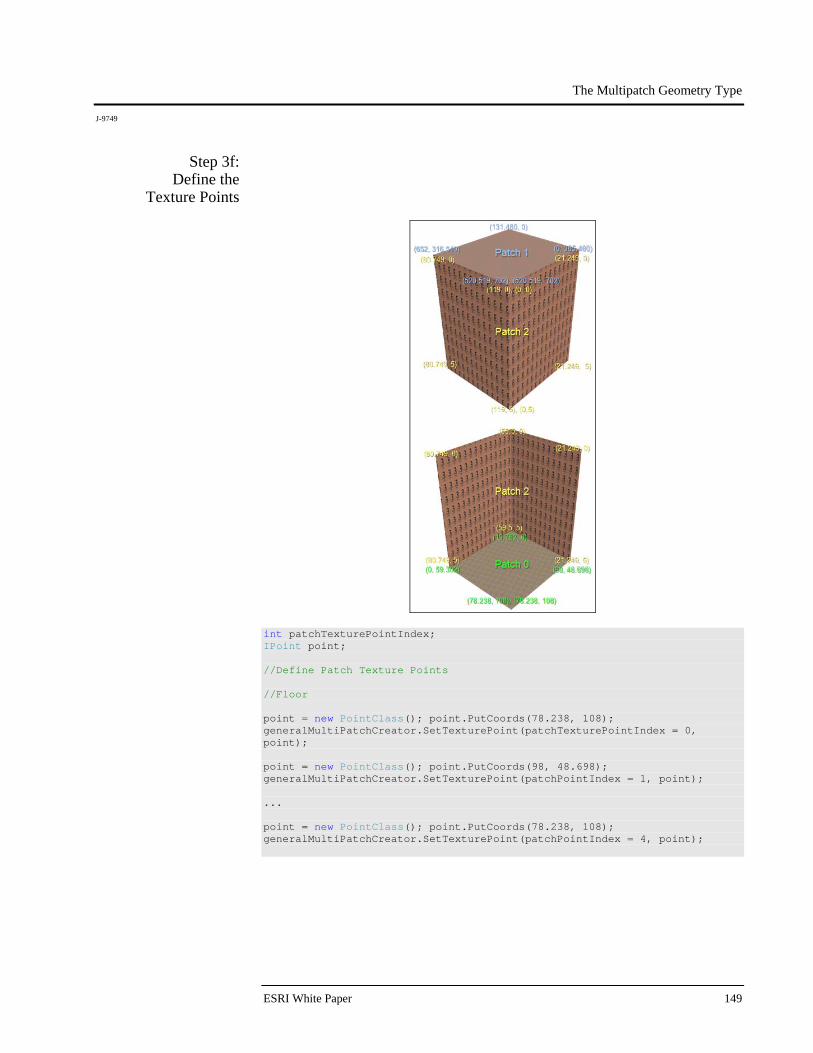
The Multipatch Geometry Type
J-9749
ESRI White Paper 149
Step 3f: Define the
Texture Points
int patchTexturePointIndex; IPoint point; //Define Patch Texture Points //Floor point = new PointClass(); point.PutCoords(78.238, 108); generalMultiPatchCreator.SetTexturePoint(patchTexturePointIndex = 0, point); point = new PointClass(); point.PutCoords(98, 48.698); generalMultiPatchCreator.SetTexturePoint(patchPointIndex = 1, point); ... point = new PointClass(); point.PutCoords(78.238, 108); generalMultiPatchCreator.SetTexturePoint(patchPointIndex = 4, point);

The Multipatch Geometry Type
J-9749
December 2008 150
//Roof point = new PointClass(); point.PutCoords(520.519, 702); generalMultiPatchCreator.SetPoint(patchPointIndex = 5, point); point = new PointClass(); point.PutCoords(0, 385.460); generalMultiPatchCreator.SetPoint(patchPointIndex = 6, point); ... point = new PointClass(); point.PutCoords(520.519, 702); generalMultiPatchCreator.SetPoint(patchPointIndex = 9, point); //Wall point = new PointClass(); point.PutCoords(0, 5); generalMultiPatchCreator.SetPoint(patchPointIndex = 10, point); point = new PointClass(); point.PutCoords(0, 0); generalMultiPatchCreator.SetPoint(patchPointIndex = 11, point); ... point = new PointClass(); point.PutCoords(119, 0); generalMultiPatchCreator.SetPoint(patchPointIndex = 19, point); Texture vertices are defined in a manner similar to geometry vertices, this time using the GeneralMultiPatchCreator SetTexturePoint() method instead. A texture can be stretched to fit a patch by setting the texture coordinate at the patch's upper left corner to (0, 0) and the texture coordinate at the patch's lower right corner to (1, 1). The texture can be repeated or tiled by increasing "1" in the coordinates (1, 1) to the number of times the texture should be repeated in the horizontal and vertical directions, respectively. For example, the fact that the wall patch has texture coordinates ranging from (0, 0) to (119, 5) indicates that the WallPatch.jpg image is to be repeated 119 times in the horizontal direction and 5 times in the vertical direction. The SetTextureWKSPoint () method can be used in conjunction with WKSPoint struct representing each texture point as an efficient alternative to the combination of SetTexturePoint() and Point objects.

The Multipatch Geometry Type
J-9749
ESRI White Paper 151
Step 3g: Define the Ms,
IDs, and Normals
int patchPointIndex; double m; int id; IVector3D normalVector3D; //Define Patch Points //Floor generalMultiPatchCreator.SetM(patchPointIndex = 0, m = 0); generalMultiPatchCreator.SetID(patchPointIndex = 0, id = 0); generalMultiPatchCreator.SetM(patchPointIndex = 1, m = 0.25); generalMultiPatchCreator.SetID(patchPointIndex = 1, id = 1); ... generalMultiPatchCreator.SetM(patchPointIndex = 4, m = 1); generalMultiPatchCreator.SetID(patchPointIndex = 4, id = 4); //Roof generalMultiPatchCreator.SetM(patchPointIndex = 5, m = 0); generalMultiPatchCreator.SetID(patchPointIndex = 5, id = 0); normalVector3D = new Vector3DClass(); normalVector3D.SetComponents(0, 0, 1); generalMultiPatchCreator.SetNormal(patchPointIndex = 5, normalVector3D); generalMultiPatchCreator.SetM(patchPointIndex = 6, m = 0.25); generalMultiPatchCreator.SetID(patchPointIndex = 6, id = 1); normalVector3D = new Vector3DClass(); normalVector3D.SetComponents(0, 0, 1); generalMultiPatchCreator.SetNormal(patchPointIndex = 6, normalVector3D); ... generalMultiPatchCreator.SetM(patchPointIndex = 9, m = 1); generalMultiPatchCreator.SetID(patchPointIndex = 9, id = 4); normalVector3D = new Vector3DClass(); normalVector3D.SetComponents(0, 0, 1); generalMultiPatchCreator.SetNormal(patchPointIndex = 9, normalVector3D); //Wall generalMultiPatchCreator.SetM(patchPointIndex = 10, m = 0); generalMultiPatchCreator.SetID(patchPointIndex = 10, id = 0); generalMultiPatchCreator.SetM(patchPointIndex = 11, m = 0); generalMultiPatchCreator.SetID(patchPointIndex = 11, id = 1); ... generalMultiPatchCreator.SetM(patchPointIndex = 19, m = 1); generalMultiPatchCreator.SetID(patchPointIndex = 19, id = 9);

The Multipatch Geometry Type
J-9749
December 2008 152
We indicated earlier that Ms, IDs, and Normals were not needed in this example. Consequently, we set the hasMs, hasIDs, and hasNormals flags to false in step 2. For illustrative purposes, however, if we want to take advantage of these attributes, we can do so by setting the above mentioned flags to true and setting Ms, IDs, and Normals using the SetM(), SetID(), and SetNormal() methods, respectively. The above code sets Ms at each geometry point equal to the distance along the ring representing the floor or roof of the building where that geometry point is located, as a ratio between 0.0 and 1.0. Assuming a perfectly square-shaped base, the first M would be 0, the second 0.25, and the last 1.0. The code also sets IDs at each geometry point equal to the relative index or offset of each point within each patch. So, for example, the ninth point in the wall patch would have an ID of 9. Finally, Normals are added only for roof geometry vertices—pointing straight up in the positive z direction. Although such Normals can be manually specified for box-shaped multipatches, it is better to let our rendering subsystem calculate Normals on the fly—via the Flat and Smooth Shading options exposed in ArcGlobe and ArcScene. A more appropriate use case scenario of Normals would be smoothing out the edges between adjacent patches in a cylindrically or spherically shaped multipatch by setting Normals at geometry vertices located where these patches meet.
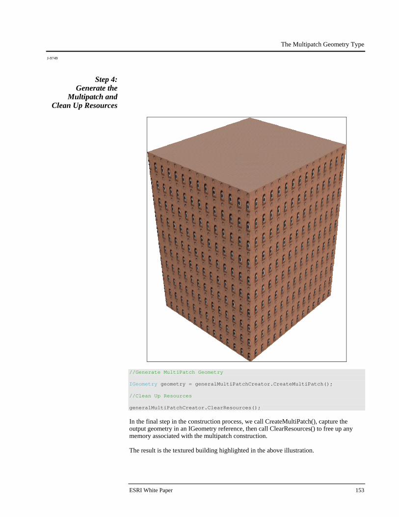
The Multipatch Geometry Type
J-9749
ESRI White Paper 153
Step 4: Generate the
Multipatch and Clean Up Resources
//Generate MultiPatch Geometry IGeometry geometry = generalMultiPatchCreator.CreateMultiPatch(); //Clean Up Resources generalMultiPatchCreator.ClearResources(); In the final step in the construction process, we call CreateMultiPatch(), capture the output geometry in an IGeometry reference, then call ClearResources() to free up any memory associated with the multipatch construction. The result is the textured building highlighted in the above illustration.

The Multipatch Geometry Type
J-9749
December 2008 154
Additional Notes Multipatch parts are, by definition, 3D geometries. Consequently, it is unnecessary to set z awareness on these parts before adding them to a multipatch container. What is required, however, is that the points added to these parts have known, defined z-values. Parts can share common boundaries, but they should not penetrate each other. If they do, the process of determining the interior and exterior of the multipatch containing them can be complicated, and area and volume calculations may return incorrect results. Rings within a single ring group should be coplanar. If they are not, then control will be lost over the precise manner in which they are rendered. This rule is not enforced, but it should be followed when creating a ring group, as it is an OpenGL 3D graphics standard. This means, for example, that a closed cube would comprise six ring groups. Each group would have a single ring. A hole in one of the sides of the cube would not alter the number of groups. Instead, an additional ring would be added to one of the groups to represent the hole. The ordering of points or vertices that make up each part is significant. Multipatch parts have positive and negative faces, or faces that point outward and faces that point inward. For a triangle strip, triangle fan, or ring, the first three vertices determine the orientation. For a triangles set, every three vertices determine the orientation of the corresponding triangle within the set. Positive faces and exterior rings are defined by adding points in a clockwise orientation. Conversely, negative faces and interior rings are defined by adding points in a counterclockwise orientation. Proper ordering of patch vertices can allow you to take advantage of back- and front-face culling to allow improvements in rendering performance and the ability to look into a multipatch feature without navigating inside of it. It can also allow you to take advantage of smooth shading in on-the-fly calculation of lighting normal vectors and return correct area and volume calculations. When making calls to the Rotate() method of IVector3D to generate vertices for a patch relative to a centerpoint and axis vector, note that the angle passed in to the Rotate() method must be negative for sequential calls to Rotate() to return points ordered in a clockwise orientation. This is because Rotate() adheres to the mathematical convention of the definition of a positive angle. Similarly, when extracting points from an existing polygon feature as a basis of constructing a 3D ring, be aware that the polygon vertices may not be ordered in a clockwise orientation. This difficulty can be attenuated by calling ITopologicalOperator.Simplify() on the polygon feature prior to the traversal of its vertices. When using the Point property getter of IPointCollection, note that when applied to a ring, a copy of a point is returned, and when applied to other than a ring (triangle strip, triangle fan, triangles), a reference to the point itself is returned. Consequently, points can be directly modified in a triangle strip, triangle fan, or triangles part by simply accessing the Point property getter and modifying one or more of the point's x-, y-, or z-values. To update or modify a ring vertex, however, the UpdatePoint() exposed by the same interface must be called.

The Multipatch Geometry Type
J-9749
ESRI White Paper 155
Additional Samples Cylinder, Sphere, Polyhedron, Pyramid, Prism, Ellipse (9.x) http://edndoc.esri.com/arcobjects/9.2/CPP_VB6_VBA_VCPP_Doc/ COM_Samples_Docs/3D_Analyst/Utilities/Visual_Basic/geomUtil.bas.htm Scene Backdrop (9.x) http://edndoc.esri.com/arcobjects/9.0/Samples/3D_Analyst/Visualization/ArcScene/ Scene_Backdrop/Scene_Backdrop.htm Textured Multipatch (9.x) http://edndoc.esri.com/arcobjects/9.0/Samples/3D_Analyst/Visualization/Symbology/ TexturedMultipatch/TexMltPch.htm Build a Surface on a Sphere (8.x) http://edndoc.esri.com/arcobjects/8.3/Samples/3D%20Analyst/Geometry/ BuildSurfaceSphere/BuildSurfaceSphere.htm

No. GS-35F-5086H
Printed in USA
ESRI International Offices
ESRI Regional Offices
Olympia 360-754-4727
St. Louis 636-949-6620
Minneapolis 651-454-0600
Boston 978-777-4543
Washington, D.C. 703-506-9515
Charlotte 704-541-9810
San Antonio 210-499-1044
Denver 303-449-7779
California 909-793-2853 ext. 1-1906
1-800-GIS-XPRT (1-800-447-9778)
www.esri.com
Locate an ESRI value-added reseller near you at
www.esri.com/resellers
Outside the United States, contact your local ESRI distributor. For the number of your distributor, call ESRI at 909-793-2853, ext. 1-1235, or visit our Web site at
www.esri.com/distributors
For More Information
ESRI 380 New York Street Redlands, California 92373-8100 USA
Phone: 909-793-2853Fax: 909-793-5953 E-mail: [email protected]
For more than 35 years, ESRI has
been helping people make better
decisions through management
and analysis of geographic
information. A full-service GIS
company, ESRI offers a framework
for implementing GIS technology
and business logic in any
organization from personal GIS on
the desktop to enterprise-wide GIS
servers (including the Web) and
mobile devices. ESRI GIS solutions
are flexible and can be customized
to meet the needs of our users.
Philadelphia 610-644-3374
Australia www.esriaustralia.com.au
Belgium/Luxembourg www.esribelux.com
Bulgaria www.esribulgaria.com
Canada www.esricanada.com
Chile www.esri-chile.com
China (Beijing) www.esrichina-bj.cn
China (Hong Kong) www.esrichina-hk.com
Eastern Africa www.esriea.co.ke
Finland www.esri-finland.com
France www.esrifrance.fr
Germany/Switzerland www.esri-germany.de www.esri-suisse.ch
Hungary www.esrihu.hu
India www.esriindia.com
Indonesia www.esrisa.com.my
Italy www.esriitalia.it
Japan www.esrij.com
Korea www.esrikr.com
Lebanon www.esrilebanon.com
Malaysia www.esrisa.com.my
Muscat www.esrimuscat.com
Netherlands www.esri.nl
Northeast Africa www.esrinea.com
Poland www.esripolska.com.pl
Portugal www.esri-portugal.pt
Romania www.esriro.ro
Singapore www.esrisa.com
Spain www.esri-es.com
Sweden www.esri-sgroup.se
Thailand www.esrith.com
Turkey www.esriturkey.com.tr
United Kingdom www.esriuk.com
Venezuela www.esriven.com