Embed Size (px)
Citation preview

The jigs and fixtures are the economical ways to produce a
component in mass production system.
These are special work holding and tool guiding device
Quality of the performance of a process largely influenced by the
quality of jigs and fixtures used for this purpose.
The main purpose of a fixture is to locate and in the cases hold a
work piece during an operation
A jig differs from a fixture in the sense that it guides the tool to its
correct position or towards its correct movement during an operation
in addition to locating and supporting the work piece.
Mechanical Department, DCE
Designing of jigs and fixtures depends upon so many factors. These
factors are analysed to get design inputs for jigs and fixtures
(a) Study of work piece and finished component size and geometry.
(b) Type and capacity of the machine, its extent of automation.
(c) Provision of locating devices in the machine.
(d) Available clamping arrangements in the machine.
(e) Available indexing devices, their accuracy.
(f) Evaluation of variability in the performance results of the machine.
(g) Rigidity and of the machine tool under consideration.
(h) Study of ejecting devices, safety devices, etc.
(i) Required level of the accuracy in the work and quality to be
produced.
Mechanical Department, DCE

Mechanical Department, DCE

The location refers to the establishment of a desired relationship between
the work piece and the jigs or fixture correctness of location directly
influences the accuracy of the finished product.
The jigs and fixtures are desired so that all undesirable movements of the
work piece can be restricted.
Determination of the locating points and clamping of the work piece serve
to restrict movements of the component in any direction, , while setting it
in a particular pre-decided position relative to the jig.
Before deciding the locating points it is advisable to find out the all
possible degrees of freedom of the work piece.
Then some of the degrees of freedom or all of them are restrained by
making suitable arrangements.
Mechanical Department, DCE

Mechanical Department, DCE

Considering the six degree of freedom of a rectangular block as shown in
Figure
It is made to rest on several points on the jig body.
Provide a rest to workpiece on three points on the bottom x-y surface.
This will stop the movement along z-axis, rotation with respect to x-axis
and y-axis.
Supporting it on the three points is considered as better support then one
point or two points
Rest the workpiece on two points of side surface (x-z), this will fix the
movement of workpiece along y-axis and rotation with respect to z-axis
Provide a support at one point of the adjacent surface (y-z) that will fix
other remaining free movements.
Mechanical Department, DCE

This principle of location of fixing points on the workpiece is also
named as 3-2-1 principle of fixture design as number of points
selected at different faces of the workpiece are 3, 2 and 1
respectively.
Mechanical Department, DCE

There are different methods used for location of a work
The locating arrangement should be decided after studying the type
of work, type of operation, degree of accuracy required.
Volume of mass production to be done also mattes a lot
Different locating methods are described below.
Flat Locator :
Flat locators are used for location of flat machined surfaces of the
component
Three different examples which can be served as a general principle
of location are described here for flat locators
Mechanical Department, DCE

Mechanical Department, DCE

A flat surface locator can be used as shown in first figure
In this case an undercut is provided at the bottom where two
perpendicular surfaces intersect each other.
This is made for swarf clearance.
The middle figure shows flat headed button type locator.
There is no need to made undercut for swarf clearance.
The button can be adjusted to decide very fine location of the
workpiece.
There can be a vertical button support as shown in third figure,
which is a better arrangement due to its capacity to bear end load
and there is a provision for swarf clearance automatically. Mechanical Department, DCE
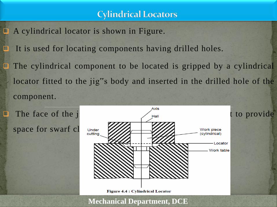
A cylindrical locator is shown in Figure.
It is used for locating components having drilled holes.
The cylindrical component to be located is gripped by a cylindrical
locator fitted to the jig‟s body and inserted in the drilled hole of the
component.
The face of the jig‟s body around the locator is undercut to provide
space for swarf clearance.
Mechanical Department, DCE
A conical locator is illustrated in Figure 4.5.
This is used for locating the workpieces having cylindrical hole in
the workpiece. The workpiece is found located by supporting it over
the conical locator inserted into the drilled hole of the workpiece.
A conical locator is considered as superior as it has a capacity to
accommodate a slight variation in the hole diameter of the
component without affecting the accuracy of location.
Degree of freedom along z-axis can also be restrained by putting a
template over the workpiece with the help of screws.
Mechanical Department, DCE

.
Mechanical Department, DCE

Jack pin locator is used for supporting rough workpieces from the
button as shown in Figure .
Height of the jack pin is adjustable to accommodate the workpieces
having variation in their surface texture.
So this is a suitable method to accommodate the components which
are rough and un-machined.
Mechanical Department, DCE
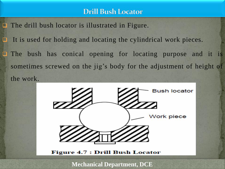
The drill bush locator is illustrated in Figure.
It is used for holding and locating the cylindrical work pieces.
The bush has conical opening for locating purpose and it is
sometimes screwed on the jig’s body for the adjustment of height of
the work.
Mechanical Department, DCE

This is quick and effective method of locating the workpiece with
desired level of accuracy.
This is used for locating the circular and semi-circular type of
workpieces as shown in Figure .
The main part of locating device is Vee shaped block which is
normally fixed to the jig.
This locator can be of two types fixed Vee locator and adjustable Vee
locator.
The fixed type locator is normally fixed on the jig and adjustable
locator can be moved axially to provide proper grip of Vee band to
the work piece.
Mechanical Department, DCE

Mechanical Department, DCE

To restrain the workpiece completely a clamping device is required in
addition to locating device and jigs and fixtures
A clamping device holds the workpiece securely in a jig or fixture
against the forces applied over it during on operation
Basic requirement of a good clamping device are listed below :
It should rigidly hold the workpiece
The workpiece being clamped should not be damaged due to
application of clamping pressure by the clamping unit
The clamping pressure should be enough to over come the operating
pressure applied on the workpiece as both pressure act on the
workpiece in opposite directions
Clamping device should be capable to be unaffected by the
vibrations generated during an operation
Mechanical Department, DCE

Common strap type clamping :
Mechanical Department, DCE

Mechanical Department, DCE

Mechanical Department, DCE

Use of quick acting nut :
Mechanical Department, DCE

Mechanical Department, DCE

Jigs are fabricated in different pieces and joined together by
welding.
Normally jigs are made of hardened steel, which are wear
resistant, corrosion resistant, and thermally in sensitive.
Their dimensional accuracy directly influences the accuracy of
performance of the operations where these are used.
Mechanical Department, DCE

Drilling Jigs
Drilling jigs are used for large number of operations. Different types of
drilling jigs are described below
Template Jig :
It is simply a plate made to the shape and size of the work piece;
with the require number of holes made it .
It is placed on the work piece and the hole will be made by the drill;
which will be guided through the holes in the template plate should
be hardened to avoid its frequent replacement
This type of jig is suitable if only a few part are to be made .
Mechanical Department, DCE

Plate Type Jig
This is an improvement of the template type of jig
In place of simple holes, drill bushes are provided in the plate
to guide the drill
The work piece can be clamped to the plate and holes can be
drilled.
The plate jig are employed to drill holes in large parts,
maintaining accurate spacing with each other.
Mechanical Department, DCE

Open Type Jig
In this jig the top of the jig is open; the work piece is placed on
the top.
Mechanical Department, DCE

Box Type Jig
When the holes are to drill more than one plane of the work
piece , the jig has to be provided with equivalent number of
bush plates.
For positioning jig on the machine table feet have to be
provided opposite each drilling bush plate
One side of the jig will be provided with a swinging leaf for
loading and unloading the work piece, such a jig would take the
form of a box.
Mechanical Department, DCE

Channel jig
The channel jig is a simple type of jig having channel like cross
section
The component is fitted within the channel is located and clamped
by locating the knob.
The tool is guided through the drill bush.
Mechanical Department, DCE

Leaf Jig
It is also a sort of open type jig , in which the top plate is arrange to
swing about a fulcrum point
so that it is completely clears the jig for easy loading and unloading
of the work piece
The drill bushes are fitted into the plates , which is also known as
leaf , latch or lid.
Mechanical Department, DCE

Fixtures are designed specifically for an operation and so these are
named on the base of the operation to be carried out with their help
Fixtures are used to hold the work piece properly to carryout the
operations.
Different types of fixtures are listed below
(a) Turning fixtures
(b) Milling fixtures
(c) Fixture for grinding
(d) Fixture for broaching
(e) Fixture for boring/drilling
(f) Tapping fixture
(g) Fixture for welding
(h) Assembling fixture
Mechanical Department, DCE
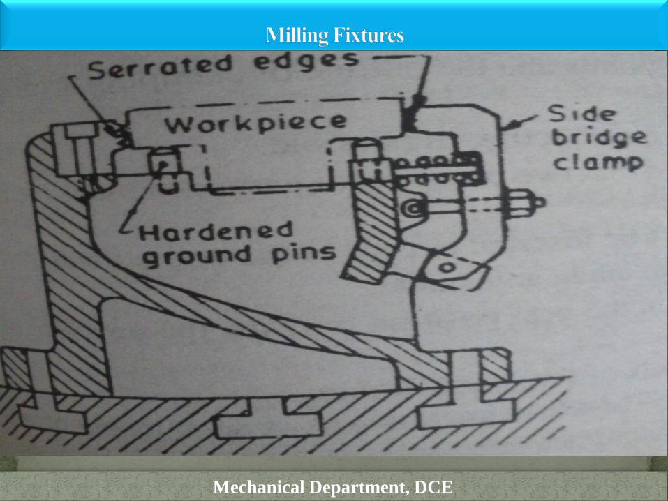
Fixtures used to perform different types of milling operations are
called milling fixtures
A Milling fixture is a work holding device which is firmly clamped
to the table of the milling machine
It holds the work piece in correct position as the table movement
carries it past the cutter or cutters
Mechanical Department, DCE
Mechanical Department, DCE
Jigs is very important in manufacturing industry
smooth and easier to operations
(a) Productivity:
Jigs eliminate individual marking
Positioning and frequent checking.
This reduces operation time and increases productivity.
(b) Inter changeability:
Jigs facilitate uniform quality in manufacture.
There is no need of frequent changes for selective assembly.
Any part of the machine would fit properly in assembly.
similar components are interchangeable.
Mechanical Department, DCE

(c) Skill reduction:
Jigs simplify locating and clamping of the work-pieces
Tool guiding elements ensure correct positioning of the tools with
respect to the work pieces.
There is no need for skilful setting of the work-piece or tool
Any average person can be trained to use jigs.
The replacement of a skilled workman with unskilled labour can
effect substantial saving in labour cost
Mechanical Department, DCE

(d) Cost reduction
Higher production,
reduction in scrap,
easy assembly and
savings in labour costs
result in substantial reduction in the cost of work-pieces produced with
jigs
Mechanical Department, DCE